DEVELOPMENT OF VIRTUAL CONTROL PANEL FOR SINGLE SPINDLE CONFIGURATION 2-AXIS FILAMENT WINDING MACHINE (SSFWM) VICNESWARAN S/O KUPPUSAMY This thesis is submitted as partial fulfillment of the requirements for the award of the Bachelor of Electrical Engineering (Hons.) (Electronics) Faculty of Electrical & Electronics Engineering Universiti Malaysia Pahang 17 NOVEMBER, 2008
Transcript
DEVELOPMENT OF VIRTUAL CONTROL PANEL FOR SINGLE SPINDLE
This thesis is submitted as partial fulfillment of the requirements for the award of the
Bachelor of Electrical Engineering (Hons.) (Electronics)
Faculty of Electrical & Electronics Engineering
Universiti Malaysia Pahang
17 NOVEMBER, 2008
DEVELOPMENT OF VIRTUAL CONTROL PANEL FOR SINGLE
SPINDLE CONFIGURATION 2-AXIS FILAMENT WINDING
MACHINE (SSFWM)
VICNESWARAN S/O KUPPUSAMY
UNIVERSITI MALAYSIA PAHANG
“I hereby acknowledge that the scope and quality of this thesis is qualified for the award
of the Bachelor Degree of Electrical Engineering (Electronics)”
Signature : ________________________
Name : ADDIE IRAWAN HASHIM
Date : 23 OCTOBER 2008
ii
I declare that this thesis entitled “Development of virtual control panel for single spindle
configuration 2-axis filament winding machine (SSFWM)” is the result of my own
research except as cited in the references. The thesis is not been accepted for any degree
is not concurrently submitted in candidature of any other degree.
Signature : _______________________________
Author : VICNESWARAN S/O KUPPUSAMY
Date : 17 November 2008
iii
To my beloved father, mother, brother and sisters.
iv
ACKNOWLEDGEMENT
In preparing this thesis, I was in contact with many people, researchers,
academicians, and practitioners. They have contributed towards my understanding and
thoughts. In particular, I wish to express my sincere appreciation to my main thesis
supervisor, Mr. Addie Irawan Bin Hashim, for encouragement, guidance, critics and
friendship, advices and motivation. Without his continued support and interest, this
thesis would not have been the same as presented here.
My fellow postgraduate students should also be recognized for their support. My
sincere appreciation also extends to all my colleagues and others who have provided
assistance at various occasions. Their views and tips are useful indeed. Unfortunately, it
is not possible to list all of them in this limited space. I am grateful to all my family
members.
v
ABSTRACT
This project is focused on developing the virtual control panel for single spindle
configuration 2-axis filament winding machine (SSFWM) using Visual Basic 6.0. The
software will interface with MMDS-RTD module Alpha version developed under the
RDU070330 research project in Faculty of Electrical & Electronics Engineering, UMP.
The MMDS-RTD module Alpha version which is capable of drive DC motor and Stepper
motor only. In the software system, algorithms are designed to perform calculation for
mathematical equation of fiber density, fiber width and product to calculate the optimal
machine configuration such as number of running, velocities rotation of mandrel,
velocities of carriage moment and angle of rotation. With this software system, user only
need to enter the value of fiber density, diameter of mandrel, winding angle then the
system will show the output their need and automatically send command to MMDS-RTD
module Alpha version and control the filament winding machine. Furthermore the main
idea is to transfer a fiber mould parameter equation into visual basic programming code.
And from the programming code control the actuators on filament winding machine to
meet with the setting given by user. This control panel capability control the movement
of filament winding machine according to input parameter insert by user. Finally; the
process is run continuously until the mandrel surface was fully covered by the
composites.
vi
ABSTRAK
Projek ini tertumpu kepada pembangunan panel kawalan maya untuk mesin belitan
filament 2-paksi dengan menggunakkan Visual Basic 6.0.Perisian ini akan berinteraksi
dengan modul MMDS-RTD versi Alpha yang di bangunkan di bawah projek
penyelidikan RDU070330 oleh Fakulti Kejuruteraan Elektrik dan Elektronik,UMP.
Modul MMDS-RTD versi Alpha ini berupaya untuk mengawal 2 jenis motor sahaja iaitu
motor stepper dan motor DC .Dalam sistem perisian, algorithms di reka untuk kiraan
persamaan matematik bagi density fiber ,lebar fiber dan diameter produk untuk
mendapatkan konfigurasi mesin yang optima seperti bilangan kitaran,halaju putaran
mandrel,halaju carriage dan sudut belitan. Dengan sistem perisian ini pengguna hanya
perlu masukkan nilai formula fiber density,luas fiber,diameter mandrel serta diameter
produk dan ia akan secara automatik hantar ke modul MMDS-RTD versi Alpha serta
mengawal mesin belitan filament. Dalam projek ini,idea utama ialah untuk menukarkan
parameter fiber persamaan dalam bentuk kod program visual basic. Dan daripada kod
program mengawal pergerakan motor pada mesin belitan filamen yang serasi dengan nilai
yang di set oleh penguna.Panel kawalan ini berupaya untuk mengawal operasi mesin
belitan filament winding berdasarkan parameter yang di masukkan oleh
pengguna.Akhirnya,process operasi mesin yang berterusan akan menyebabkan mandrel
di penuhi dengan belitan filament.
vii
TABLE OF CONTENTS
CHAPTER TITLE PAGE DECLARATION ii
DEDICATION iii
ACKNOWLEDGEMENT iv
ABSTRACT v
ABSTRAK vi
TABLE OF CONTENT vii
LIST OF FIGURES x
LIST OF TABLES xii
LIST OF ABBREVIATIONS xiii
LIST OF APPENDICES xiv
1 INTRODUCTION 1
1.1 Background 1
1.2 Objective 2
1.3 Scopes 2
1.4 Thesis Organization 3
2 LITERATURE REVIEW 4
2.1 Filament Winding Machine 4
2.2 FWM Applications 5
2.3 Composite Component Design and Optimization 6
viii
2.3.1 Fiber Winding Techniques and Patterns 9
2.3.2 FWM Units 11
2.4 Visual Basic (VB) 13
3 FILAMENT WINDING MACHINE OPERATION 15
3.1 Basic Wiring of Controller 15
3.2 SSFWM Design and Operation 16
3.3 MMDS-RTD Configuration for SSFWM 19
4 SOFTWARE CONTROL PANEL DESIGN 21
4.1 Overview on SSFWM Software Control Panel Design 21
4.2 Input Parameters for User Interfaces 22
4.3 Output Parameters for Machine Operations 25
4.4 Graphical User Interface (GUI) 27
5 RESULT AND DISCUSSION
5.1 Introduction 30
5.2 Testing results 30
5.2.1 Operation on Virtual Control Panel single 31
Spindle configuration 2-axis filament
Winding machine (SSFWM)
5.2.2 Discussion on the Performances of SSFWM. 33
ix
6 CONCLUSION & RECOMMENDATION 38
6.1 Conclusion 38
6.2 Recommendation 38
6.3 Costing & Commercialization 39
REFERENCES 40 APPENDICES APPENDIX A 42- 43 APPENDIX B 44- 47
x
LIST OF FIGURES
FIGURE NO TITLE PAGE
2.1 Circumferential or hoop winding 10
2.2 Helical winding 10
2.3 Polar winding 11
3.1 Terminal Point for Motors 16
3.2 SSFWM Features 16
3.3 The movement of SSFWM 17
3.4 Schematic of the wet filament winding process 18
3.5 MMDS-RTD connection on SSFWM 19
3.6 MMDS-RTD command for SSFWM application 20
4.1 System structure for software control panel for SSFWM 21
4.2 Software Control Panel of SSFWM user procedures 26
4.3 GUI form of Software Control Panel for SSFWM 27
4.4 SSFWM default setting form 28
4.5 SSFWM default setting procedures 29
5.1 Showed the result on the Control Panel for SSFWM. 31
5.2 Angle Of holder (45 Degree Clock Wise) 33
5.3 Moving of Carriage Rail from left to right 34
5.4 Moving of Carriage Rail from right to left 34
xi
5.5 Angle Of holder (90 Degree Counter Clock Wise) 35
5.6 The dry fiber covered the mandrel 35
5.7 The fiber half covered the mandrel 36
xii
LIST OF TABLES
TABLE NO TITLE PAGE 5.1 User Parameter Settings Parameter 32
xiii
LIST OF ABBREVIATIONS
DC - Direct Current AC - Alternating Current MMDS - Multiple Motor Drive System RTD - Real Time Data Acquisitions EMF - Electromagnetic Force SSFWM - single spindle configuration 2-axis filament winding machine GUI - Graphical User Interface COM - Component Object Model
xiv
LIST OF APPENDICES
APPENDIX TITLE PAGE
A Single Spindle Configuration 42-43
2-Axis Filament Winding Machine (SSFWM)
B MMDS-RTD module Alpha version 44-47
1
CHAPTER 1
INTRODUCTION
1.1 Background
Filament winding consists of winding continuous ravings of fiber onto a rotating mandrel
in predetermined patterns. This method of manufacturing provides the greatest control
over fiber placement and uniformity of structure. In the wet winding method, the fiber
picks up resin either by passing through a resin bath or from a metered application
system. After several layers are wound, the component is cured and removed from the
mandrel (or in some cases the mandrel becomes part of the component). Filament
winding is traditionally used to produce pressure vessels, pipe, rocket motor casings,
tanks, ducting, golf club shafts and other symmetric parts. Filament winding technology
has been expanded to include non-cylindrical, non-spherical composite parts thanks in
part to advancements in computer and software technology. [1]
This project is focus on developing the virtual control panel for 2-axis configuration
filament winding machine using Visual Basic 6.0. The software will interface with
MMDS module card developed under the RDU070330 research project in Faculty of
Electrical & Electronics Engineering, UMP. The MMDS interface module capable of
controlling DC.AC & Stepper motor simultaneously which 2-3 motors at the same time.
This module consist of 3 stage that is full-bridges,8 channel of converters & 3 channel for
Back-EMF input reading [2].
2
In the system, the design the software for calculating from equation ion of fiber density,
fiber width and product to calculate the optimal machine configuration such as number
of running, velocities rotation of mandrel, velocities of carriage moment and angle of
rotation. With this system, user only need to enter the value of fiber density, diameter of
mandrel, winding angle then the system will show the output their need and automatically
send command to MMDS module card and control the filament winding machine.
1.2 Objective
The objective of this project is to develop the Software Control Panel for single spindle
configuration 2-axis filament winding machine (SSFWM) using Visual Basic 6.0
development program. In this project, the main idea is to transfer a fiber mould parameter
equations into visual basic programming codes. And from the programming code control
the actuators on filament winding machine to meet with the setting given by user.
1.3 Scopes
i. Design the software control panel (virtual instrument) that capable of
calculating and translates basic filament winding input for SSFWM motion.
ii. Design the software control panel which is capable of interfacing with
MMDS-RTD Alpha version to control carriage and holder movement of
SSFWM.
3
1.4 Thesis Organization
This thesis is combination of 6 chapters that contains the Introduction, Literature
Review, Hardware Design, Software Design, Result and Discussion, and the last chapter
is a Conclusion and Further Development of the project.
Chapter 1 is an introduction of the project. In this chapter, we will explain the
background and objectives of the project. The concept of the project and the overall
overview of the project also will be discussed in this chapter.
Chapter 2 focuses on the literature review and the methodologies for the
development of the Filament Winding Machine Process and Visual Basic 6.0 for software
design.
Chapter 3 will be discussed about filament winding machine operation. This
chapter is divided into two main sections that are basic wiring of controller and the basic
filament winding machine design/process. In basic wiring of controller, we will discuss
about the terminal block for SSFWM controller input/output. For basic filament winding
machine design/process, we will discuss about the development of the SSFWM.
Chapter 4 describes the software development of the controller. In this chapter we
will expose on how to design GUI and write program with Visual basic 6.0. In addition,
we will discuss feature about serial communication use it for send data/command to the
MMDS module cad.
Chapter 5 describes about the experimental results, expected performance and
performance limits that can be achieve by the system.
Chapter 6 provides conclusions, recommendations for further work or future
expectations for the system.
4
CHAPTER 2
LITERATURE REVIEW
2.1 Filament Winding Machine
Filament Winding is the process of winding resin-impregnated fiber or tape on a
mandrel surface in a precise geometric pattern. This is accomplished by rotating the
mandrel while a delivery head precisely positions fibers on the mandrel surface. By
winding continuous strands of carbon fiber, fiberglass or other material in very precise
patterns, structures can be built with properties stronger than steel at much lighter
weights. [3]
Filament winding machines (FWM) operate on the principles of controlling machine
motion through various axes of motion. The most basic motions are the spindle or
mandrel rotational axis, the horizontal carriage motion axis and the cross or radial
carriage motion axis. Additional axes may be added, typically a rotating eye axis or a
yaw motion axis, and when the pattern calls for more precise fiber placement further
additional axes may be added.
5
The filament winding process was originally invented to produce missile casings, nose
cones and fuselage structures, but with the passage of time industries other than defense
and aerospace have discovered the strength and versatility of filament winding. [3]
Entec Composite Machines is the world’s oldest continually operating manufacturer of
filament winding machinery, with over 40 years’ experience in the field, and has built
more multi-spindle filament winding machines than any other manufacturer. Entec
changed the face of filament winding by producing the world’s first computer-controlled
filament winding machine, and has continued to lead the industry ever since. Entec
engineers also created the world’s most-used application software for winding pattern
generation, FiberGrafiX. [3]
These contributions and countless others made over the years, along with our continued
pursuit of technological innovations, have given Entec a reputation for producing the
most durable and reliable winding machines on the market. [3]
Our staff consists of some of the industry’s most experienced mechanical engineers,
electrical engineers and software programmers. Using their skills, Entec has built the
world’s largest five-axis filament winding machine. The machine is used to produce large
wind turbine blades with a part length of 150 ft. (45.72 m), a diameter of 27 ft. (8.23 m)
and a weight in excess of 80,000 lbs. (36,287 kg). In contrast, Entec has also created
some of the world’s smallest machines for use in universities, research facilities and
commercial companies to test sample parts before going into full-scale production. [3]
6
2.2 FWM Applications
The filament winding process was originally invented to produce missile casings,
nose cones and fuselage structures, but with the passage of time industries other than
defense and aerospace have discovered the strength and versatility of filament winding.
Entec Composite Machines is the world’s oldest continually operating manufacturer
of filament winding machinery, with over 40 years’ experience in the field, and has built
more multi-spindle filament winding machines than any other manufacturer. Entec
changed the face of filament winding by producing the world’s first computer-controlled
filament winding machine, and has continued to lead the industry ever since. Entec
engineers also created the world’s most-used application software for winding pattern
generation, FiberGrafiX. [4]
Filament Winding is the process of winding resin-impregnated fiber or tape on a
mandrel surface in a precise geometric pattern. This is accomplished by rotating the
mandrel while a delivery head precisely positions fibers on the mandrel surface. By
winding continuous strands of carbon fiber, fiberglass or other material in very precise
patterns, structures can be built with properties stronger than steel at much lighter
weights. [4] A winding machine can be as simple as one axis of motion or as complicated
as five or more axis of motion to create more precise patterns for higher performance
parts. [4]
A winding machine can be as simple as one axis of motion or as complicated as five
or more axis of motion to create more precise patterns for higher performance parts.
Filament Winding is the process of winding resin-impregnated fiber or tape on a mandrel
surface in a precise geometric pattern. This is accomplished by rotating the mandrel while
a delivery head precisely positions fibers on the mandrel surface. By winding continuous
strands of carbon fiber, fiberglass or other material in very precise patterns, structures can
be built with properties stronger than steel at much lighter weights. [4]
7
2.3 Composite Component Design and Optimization
The designing of components made of fiber reinforced plastics requires a lot of
experience and know how. Unlike other manufacturing methods such as metal processing
the actual material will only appear in the production stage of the intended product. In
order to exploit the full potential of the material a suitable design is the deciding factor.
The following parameters have to be adjusted to each other: component geometry,
fibre and matrix material, laminate structure and wind ability. Naturally profitability of
the production always has to be taken into account.
Since fiber and matrix material determine the characteristics and the price of the
component, the proper choice of material is crucial. Also with production already in
progress, the quality of the product can be improved and cost reduced considerably just
by replacing the material. However, the selection of the most suitable material from the
wide variety available world wide often poses a problem. MATERIAL uses its own up to
date material database so that your new components can be designed in the best possible
way or your existing product improved. [5]
Based on the performance specifications, the next step is to calculate the laminate
structure (number and winding angles of the different layers). To this purpose
MATERIAL uses analytical laminate calculation programs and finite element analysis
software (FEA software). Once the optimal laminate structure has been found, its wind
ability and cost effectiveness has to be checked. In order to do so MATERIAL links the
process simulation system CADWIND to a FEA program. This guarantees a cost
effective and quality product. [5]
Depending on your needs, MATERIAL not only offers you the individual stages of
product development - such as selection of material, laminate calculation, FEA
calculation, and wind ability check - but a total development or optimization package.
8
When designing a new component we guarantee that you will be able to manufacture a
product of the highest technical standard at the lowest possible cost. Optimizing your
components will improve their quality and reduce your production costs. [5]
The rotary assembly consists of two structural blocks; one fixed and the other
linearly movable unit in which a 2-axis mechanically driven mandrel is mounted onto its
holders. On the fixed end, the holder is connected to a rotating shaft, which is coupled to
either a gear or a chain or belt reduction system, or directly to the motor unit. Generally,
an AC or servo-motor is used because of its greater torque capabilities and accuracy
when operating under conditions of heavy loading. For delivery system, rolls of
continuous fibers are fed into a resin bath which is mounted onto the carriage rails that
are commonly placed overhead to provide greater workroom. Generally, the shape is a
surface of revolution and may or may not include end closures. When the required
number of layers is applied, the wound form is cured and the mandrel removed. The
material properties in each layer are constant but may vary from layer to layer. The
mandrel is represented by a hollow cylinder with uniform effective wall thickness. The
mandrel and the cylinder are of equal length and are ax symmetrical, so that neither the
geometry nor the properties vary in the circumferential direction. Filament winding is
defined as [10] a technique which “produces high-strength and lightweight products;
consists basically of two ingredients; namely, a filament or tape type reinforcement and a
matrix or resin”. The concept of filament winding process had been introduced in early
1940s and the first attempt was made to develop filament-winding equipment. The
equipment that was designed in 1950s was very basic; performing the simplest tasks
using only two axes of motion (spindle rotation and horizontal carriage). By mid-1970s,
machine design once again made a dramatic shift.
9
This time the advancement of servo technology entered the realm of the machine design.
High-speed computers allowed for rapid data processing, resulting in smoother motion
and greater fiber placement accuracy. The 1980s and 1990s saw the increased use of
computer technology. Computers and motion control cards became the essential pieces of
hardware that were included in almost every machine. Machine speed control was greatly
improved; computer control systems could track position and velocity with increased
accuracy. Additional axes of motions were also incorporated into machine design;
allowing for four, five and even six axes of controlled motion.
2.3.1 Fiber Winding Techniques and Patterns
The properties of a composite product are not only dependent on the properties of fiber
and resin matrix, but are also dependent on the way by which they are processed. There
are a variety of processing techniques for fabricating composite parts/structure; resin
transfer moulding, autoclave moulding, pultrusion and filament winding. Out of these
processes, filament winding involves low cost and is the fastest technique for
manufacturing of fiber reinforced cylindrical components as high-pressure pipes and
tanks.
In filament winding process, the winding tension can easily be controlled. Winding
tension, winding angle and/or resin content in each layer of reinforcement can be varied
until the desired thickness and strength of the composite are achieved. The properties of
the finished composite can be varied by the type of winding pattern selected. In general,
there are three basic filament winding patterns which are as follows.
10
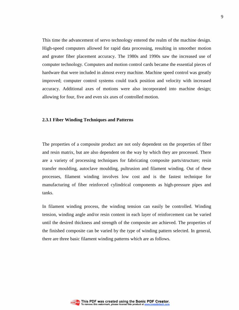
It is known as the girth or circumferential winding. In hoop winding, a high-angle helical
winding approaches an angle of 90°. Each full rotation of the mandrel advances the band
delivery by one full bandwidth as shown in Figure 2.1
Figure 2.1: Circumferential or hoop winding
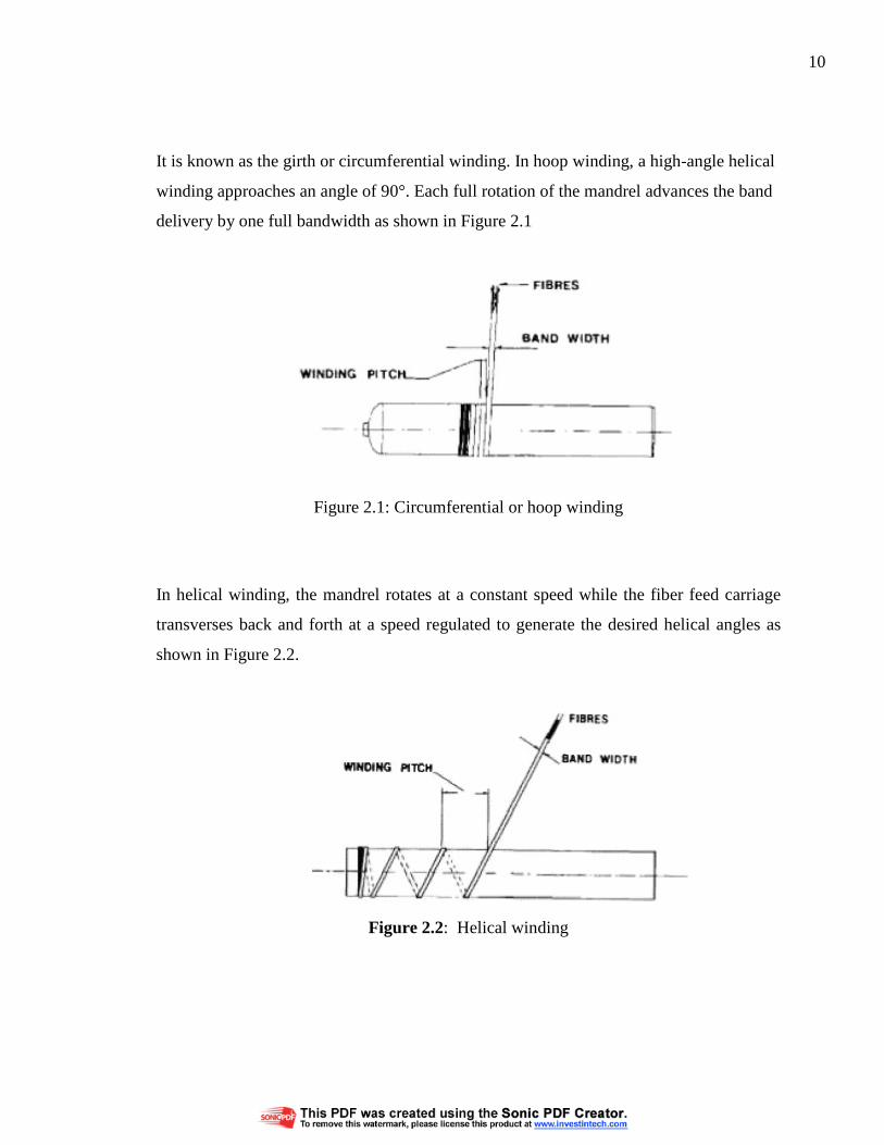
In helical winding, the mandrel rotates at a constant speed while the fiber feed carriage
transverses back and forth at a speed regulated to generate the desired helical angles as