+ All Categories
Home > Documents > Development Project of Supercritical-water Cooled …silver.neep.wisc.edu/~scw/SCPR.Hitachi.pdf ·...

Development Project of Supercritical-water Cooled …silver.neep.wisc.edu/~scw/SCPR.Hitachi.pdf ·...

Date post: 20-Apr-2018
Category:
Upload: lamdieu
View: 217 times
Download: 2 times
Share this document with a friend
29
IAE R&D Program Progress Report Development Project of Supercritical-water Cooled Power Reactors Overview, Irradiation Test and Mechanical Property Test Shigeki Kasahara Hitachi, Ltd. Toshiba Corp. Hokkaido Univ. Univ. of Tokyo SCPR:S upercritical-water C ooled P ower R eactor
Transcript

IAE R&D Program Progress ReportDevelopment Project of Supercritical-water Cooled Power Reactors

Overview, Irradiation Testand Mechanical Property Test

Shigeki Kasahara

Hitachi, Ltd.Toshiba Corp.Hokkaido Univ.Univ. of Tokyo

SCPR:Supercritical-water Cooled Power Reactor

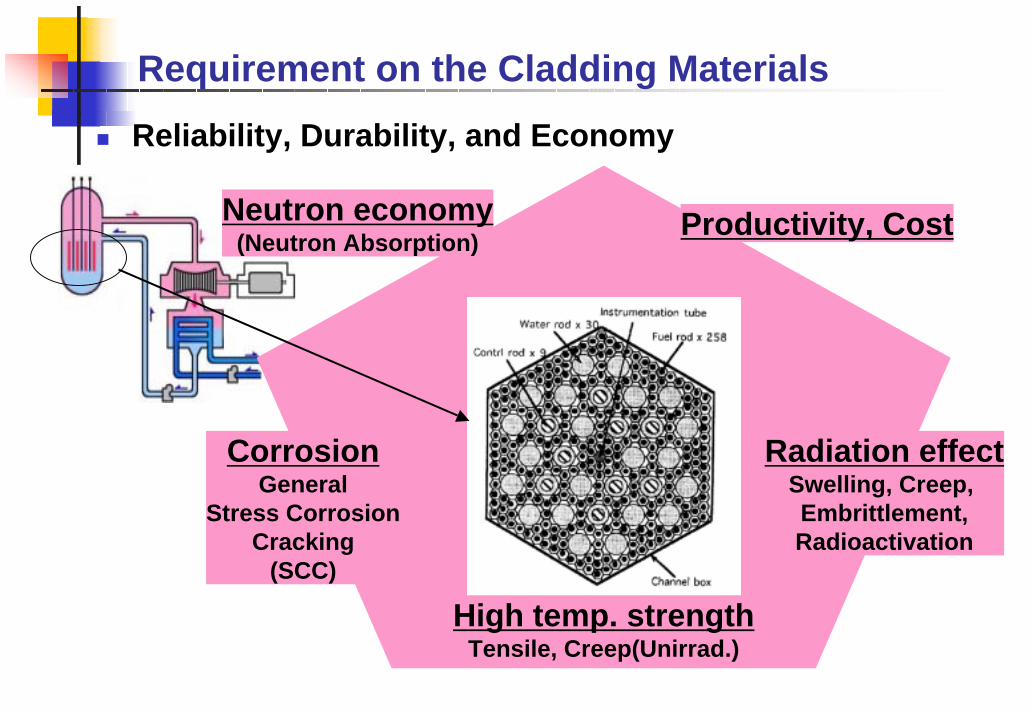
Requirement on the Cladding MaterialsReliability, Durability, and Economy

Radiation effectSwelling, Creep, Embrittlement,Radioactivation

Productivity, Cost

CorrosionGeneral

Stress CorrosionCracking

(SCC)

High temp. strengthTensile, Creep(Unirrad.)

Neutron economy(Neutron Absorption)

Design of SCPR fuel assembly

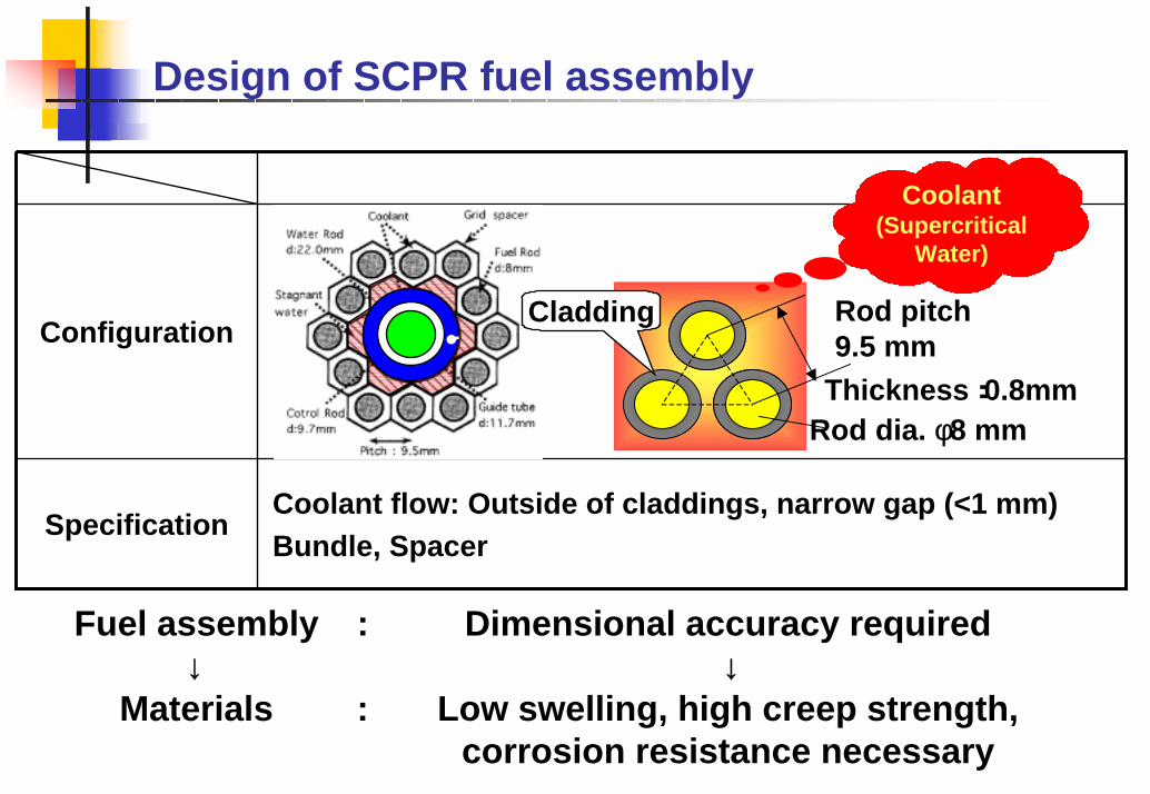
Coolant flow: Outside of claddings, narrow gap (<1 mm)Bundle, Spacer

Specification

ConfigurationRod pitch9.5 mm

Rod dia. φ8 mm

Cladding

Thickness:0.8mm

Coolant(Supercritical

Water)

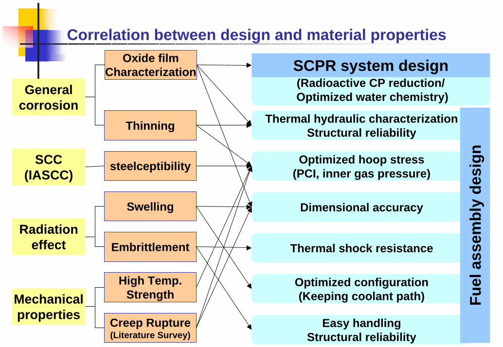
Fuel assembly : Dimensional accuracy required↓ ↓

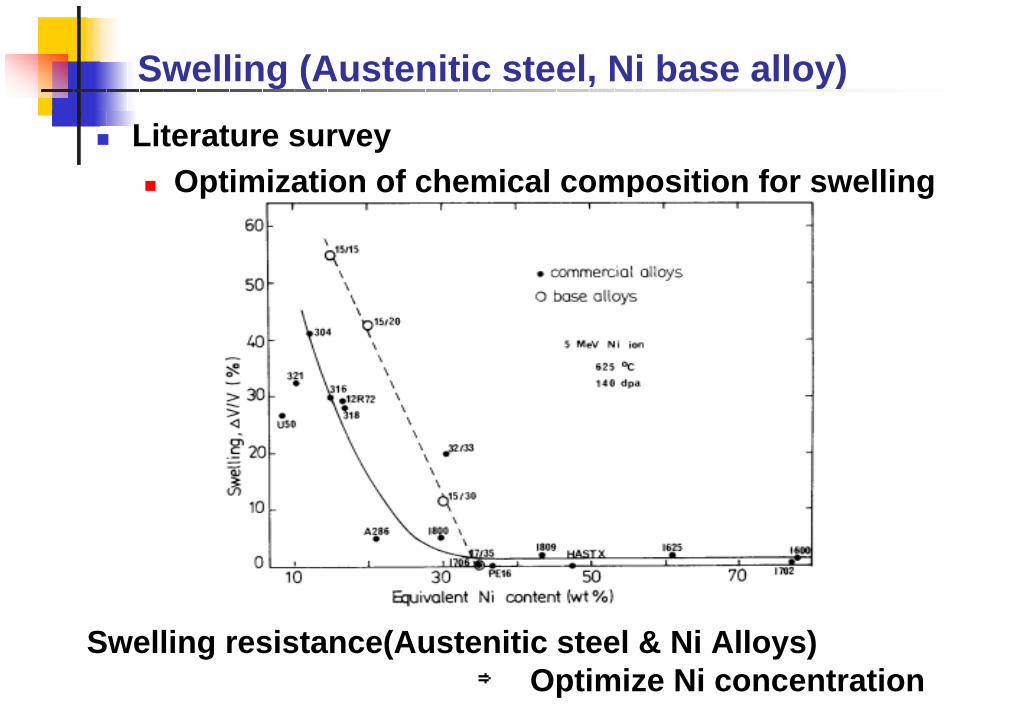
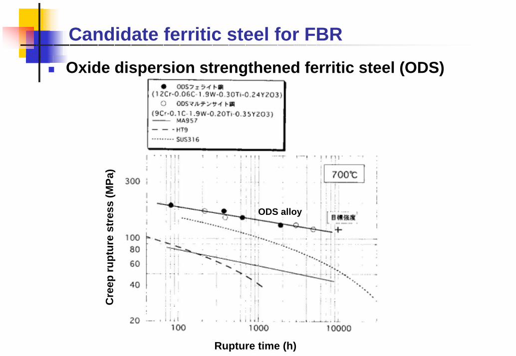
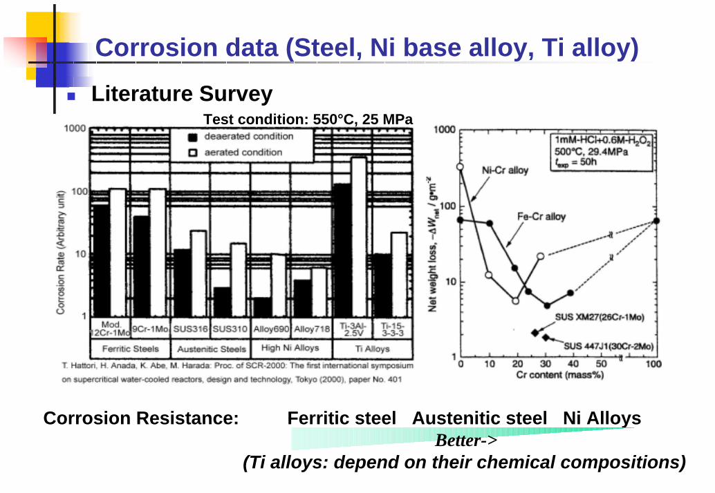
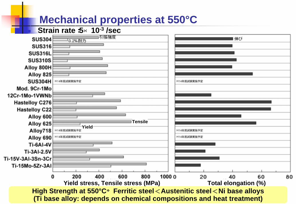
Materials : Low swelling, high creep strength,corrosion resistance necessary

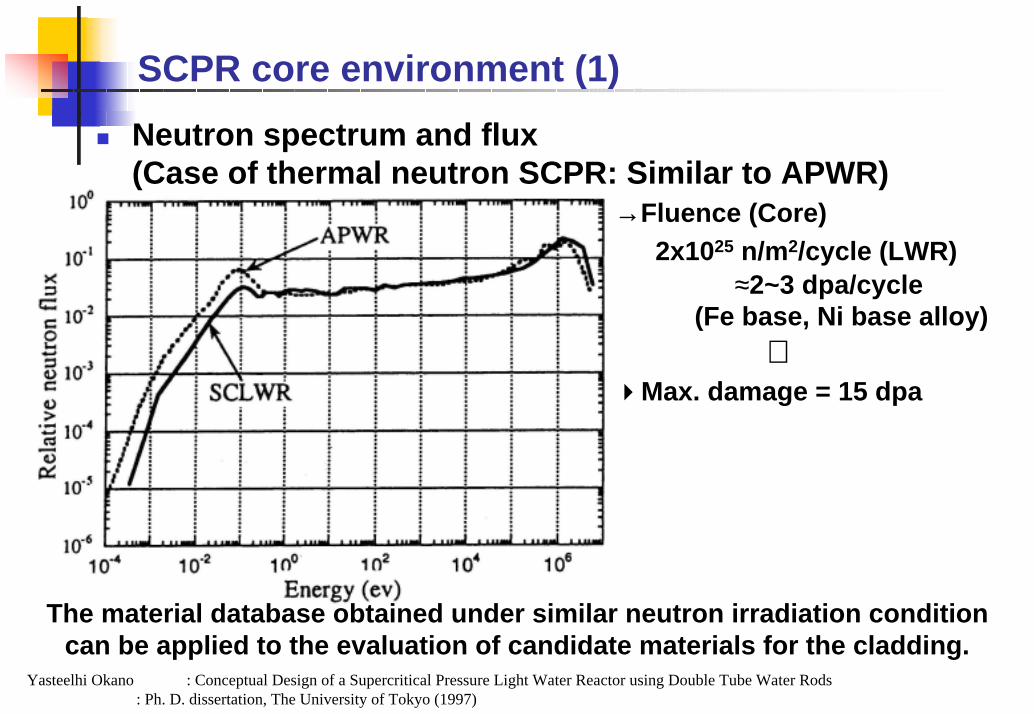
SCPR core environment (1)Neutron spectrum and flux(Case of thermal neutron SCPR: Similar to APWR)

→Fluence (Core)2x1025 n/m2/cycle (LWR)

≈2~3 dpa/cycle(Fe base, Ni base alloy)

⇓Max. damage = 15 dpa

The material database obtained under similar neutron irradiation condition can be applied to the evaluation of candidate materials for the cladding.

Yasteelhi Okano : Conceptual Design of a Supercritical Pressure Light Water Reactor using Double Tube Water Rods: Ph. D. dissertation, The University of Tokyo (1997)

SCPR core environment (2)Temperature: 300°C ~ 550°C Pressure: 25 MPa

Axial NodeKazuaki Kitou : Safety Analysis of a Supercritical Water Cooled Reactor :Ph. D. dissertation, The University of Tokyo (1998)

Material degradation issues

Swelling, Irradiation Creep,Embrittlement

due to precipitatesDatabase from FBR, Fusion Reactor

Over 400°C Under 350°C IASCC,

Radiation hardening,Embrittlement due to

dislocation loopsDatabase from LWR

Max. Temp.(Current design)

Frame work

Technical survey of current status-Technical issues relating to fuel cladding

-Surveillance of promising materials

Planning of R&D program

Preparation of examinationsMaterial Preparation &

Mechanical Property TestsTest loop design and

manufacturing

ExaminationElectron irradiation tests

-Swelling-Embrittlement

Corrosion tests-General corrosion

-SCC*)

Overall Evaluation-Proposal of Candidate Materials

-Clarification of R&D Issues in Next Phase*)SCC: Stress Corrosion Cracking

Schedule

200520022001

Literature Survey

Planning

Preparation of examinations

Corrosion Tests

Irradiation Tests

Overall evaluation

20042000FY

Item

Test loop

Materials, Mechanical properties

General CorrosionSCC

Mechanical properties (High temp.)Literature survey (Creep rupture strength)

Boiler piping materials(Austenitic, Ferritic steel)Comparison of creep strength at 600°C, 105 h

Creep strength: High Ni alloy ≥ Ferritec ≈ Austenitic

General tendency of swellingLiterature Survey

Swelling⇒Ferritic/martensitic steel< Austenitic steel

Swelling (Austenitic steel, Ni base alloy)Literature survey

Optimization of chemical composition for swelling

Swelling resistance(Austenitic steel & Ni Alloys)⇒ Optimize Ni concentration

Candidate austenitic steel for FBR

Improvement of swelling resistance (steel316)=Cold work, P, Ti, Nb, and B addition

Radiation embrittlement in ferritic steelLiterature surveyIrradiated ferritic steel ⇒

Decrease of the upper shelf energyDBTT shift

RadiationEmbrittlement

DBTT: Ductile brittle transient temperature

Candidate ferritic steel for FBROxide dispersion strengthened ferritic steel (ODS)

Cre

ep ru

ptur

e st

ress

(MPa

)

Rupture time (h)

ODS alloy

Corrosion data (Steel, Ni base alloy, Ti alloy)Literature Survey

Test condition: 550°C, 25 MPa

Corrosion Resistance: Ferritic steel Austenitic steel Ni Alloys

(Ti alloys: depend on their chemical compositions)Better->

Selection of test Materials (1) (commercial alloys)

Supercritical Fossil Fired Power Plants(High Temp. Strength, Creep)Supercritical Water Oxidation Plants (Corrosion)= Waste decompositionNuclear Power Plants(Radiation Damage)

Austenitic Steel(7)steel316L(Commercial, Modified), steel316, steel304, steel310S(Commercial, Modified), steel304H

Ferittic Steel(2)12Cr-1Mo-1WVNb(HCM12), Mod. 9Cr-1Mo

Nickel Base Alloy(8)Alloy 600, Alloy 625, Hastelloy C276, Alloy825,Hastelloy C22, Alloy 800H, Alloy 690, Alloy 718

Titanium Base Alloy(4)Ti-6Al-4V, Ti-3Al-2.5V, Ti-15V-3Al-3Sn-3Cr, Ti-15Mo-5Zr-3Al

Selection of Test Materials (2) (developed alloys)

Some developed materials (mainly nuclear fields) will be examined to evaluate their viability as candidate materials for SCPR fuel claddings.

Austenitic stainless steel→Modified 316L (Zr added)→Ultra fine grained steel→PCA (Primary candidate alloys)(If available)

Ferritic stainless steel →F82H(Low radioactivation steel: JAERI)→ODS ferritic/martensitic steel (JNC)→JFMS (Japan Ferritic Maltensitic Steel) for fusion reactors (DEMO reactor) (If available)

Screening of the candidate materials

Screening of test materials after irradiation and corrosion test

Alloy design (modification) on the screened materials(Improve the properties to meet the requirements of the cladding design)

The candidate alloys for SCPR fuel claddings will be proposed.  Plant design Fuel assembly design

Frame work of screening

Irradiation Test

Nuclear materials

Stainless steel

Fossil fired plants materials

Stainless steelNi base alloy

SCWO plants materials

Ni base alloyTi base alloy

Commercial alloys

Screening of promising alloy+ Alloy design

Proposal of the candidate materials

(Corrosion Tests)

Irradiation Test

Correlation between design and material properties

Thermal shock resistance

Easy handlingStructural reliability

Optimized configuration(Keeping coolant path)

Optimized hoop stress(PCI, inner gas pressure)

Thermal hydraulic characterizationStructural reliability

Dimensional accuracy

Oxide filmCharacterization

steelceptibility

Swelling

(Radioactive CP reduction/Optimized water chemistry)

SCPR system designGeneral

corrosionThinning

Fuel

ass

embl

y de

signSCC

(IASCC)

Radiationeffect Embrittlement

High Temp.StrengthMechanical

properties Creep Rupture(Literature Survey)

Mechanical properties at 550°CStrain rate:5×10⁻³ /sec

Yield stress, Tensile stress (MPa) Total elongation (%)

TensileYield

High Strength at 550°C⇒Ferritic steel<Austenitic steel<Ni base alloys(Ti base alloy: depends on chemical compositions and heat treatment)

Electron irradiation test (1)Electron irradiation -> Microstructure observation

Test condition:290,450,550°C x 5 dpa (1000keV electron irradiation)

Void formation=>SwellingPrecipitates formation=>Embrittlement

0.15(mm)

High voltage electron microscope(Electron irradiation):Hokkaido Univ.

Transmission electron microscope

(Microstructure observation)

Irrad. area

Electron irradiation test (2)TP: steel304 Temp:550°C Damage Rate:2x10⁻³ dpa/s

100 nm

0.03 dpa 0.5 dpa 1 dpa

5.4 dpa4.4 dpa1.6 dpa

Microstructural observation(1)Austenitic stainless steels irradiated with electrons-1

290℃ 450℃ 550℃

316L

316

100 nm100 nm 100 nm

100 nm100 nm 100 nm

290℃ 450℃ 550℃

310S

304

100 nm

100 nm

100 nm 100 nm

100 nm 100 nm

Microstructural observation(2)Austenitic stainless steels irradiated with electrons-2

Microstructural observation(3)High Ni austenitic alloys irradiated with electrons(1)

290℃ 450℃ 550℃

Alloy 800H

Alloy 825100 nm100 nm100 nm100 nm

100 nm100 nm100 nm

100 nm 100 nm 100 nm

Microstructural observation(4)High Ni austenitic alloys irradiated with electrons(2)

290℃ 450℃ 550℃

HastelloyC276

HastelloyC22

100 nm 100 nm 100 nm

100 nm 100 nm 100 nm

Microstructural observation(5)Ni base alloys irradiated with electrons

290℃ 450℃ 550℃

Alloy 625

Alloy 600

100 nm100 nm 100 nm

100 nm 100 nm 100 nm

Electron irradiation test (3)Microstructure observation => Void formation

100 nm

450°

C55

0°C

HastelloyC276Alloy825Alloy625316L 310S

Higher Ni concentration=Better void swelling resistance

Higher Ni concentration=Better void swelling resistance

Current status of the material database●Comparison of materials (Blue: Advantage, Red: Disadvantage)

Corrosion Radiation damage Mechanical Properties (High temperature) Cost

Austenitic SUS Better (A&B)

Lots of experience Good phase stability

High Swelling

(Modification required)

Improvement required

Low

Ferritic SUS Good (A)

Low Swelling Low radioactivation Good phase stability

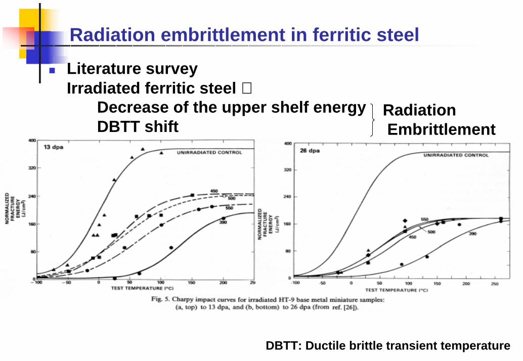
DBTT shift(High Temp)

(Precipitates?)

DBTT shift(Low Temp) Improvement required

Low

Ni base alloy (High Ni SUS)

Excellent (B)

Low Swelling

High radioactivation He embrittlement

(Precipitates?)

Good~Excellent*)

Middle~ Expensive

Ti base alloy Good~

Excellent (B)

(Limited DB) Good~Excellent *) Expensive

A: Fossil Fired Plant B: SCWO *)Depend on the chemical compositions and thermal treatment

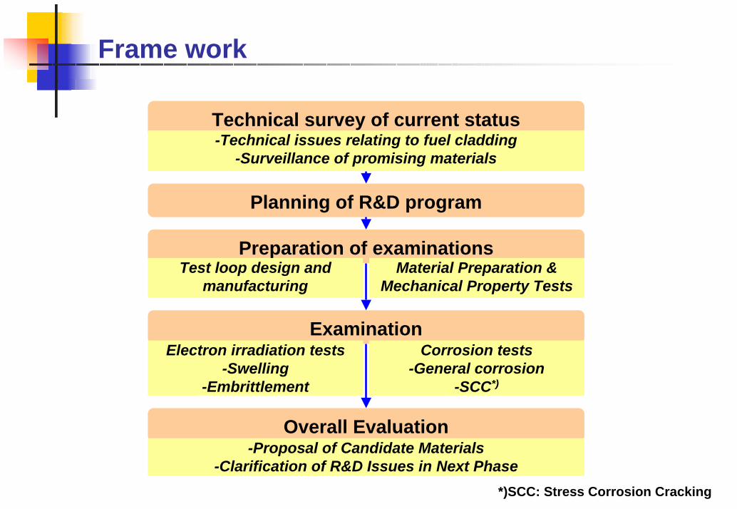
SummaryLiterature survey

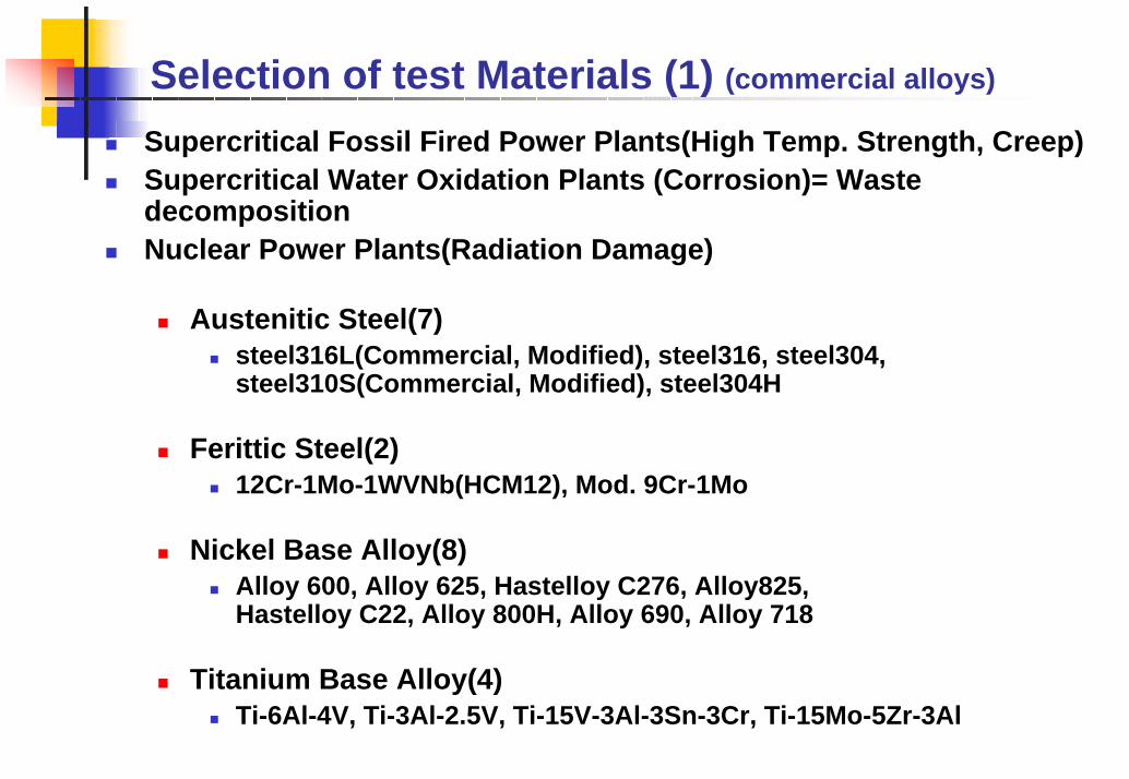
It was almost finished, and the materials for the tests have been selected.

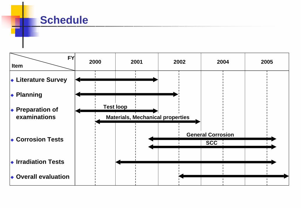
PlanningThe subjects of the development program was clarified.Test matrix of irradiation test and corrosion test were decided.

Preparation of examinationLoop facility for corrosion test was designed and manufactured. The materials for the tests have been purchased.

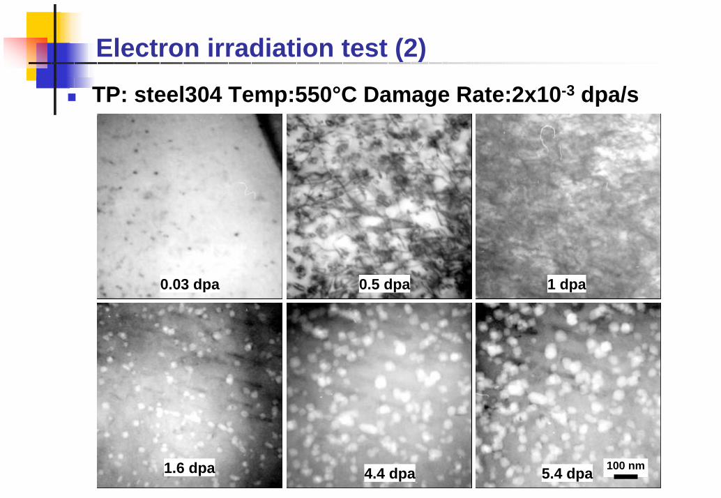
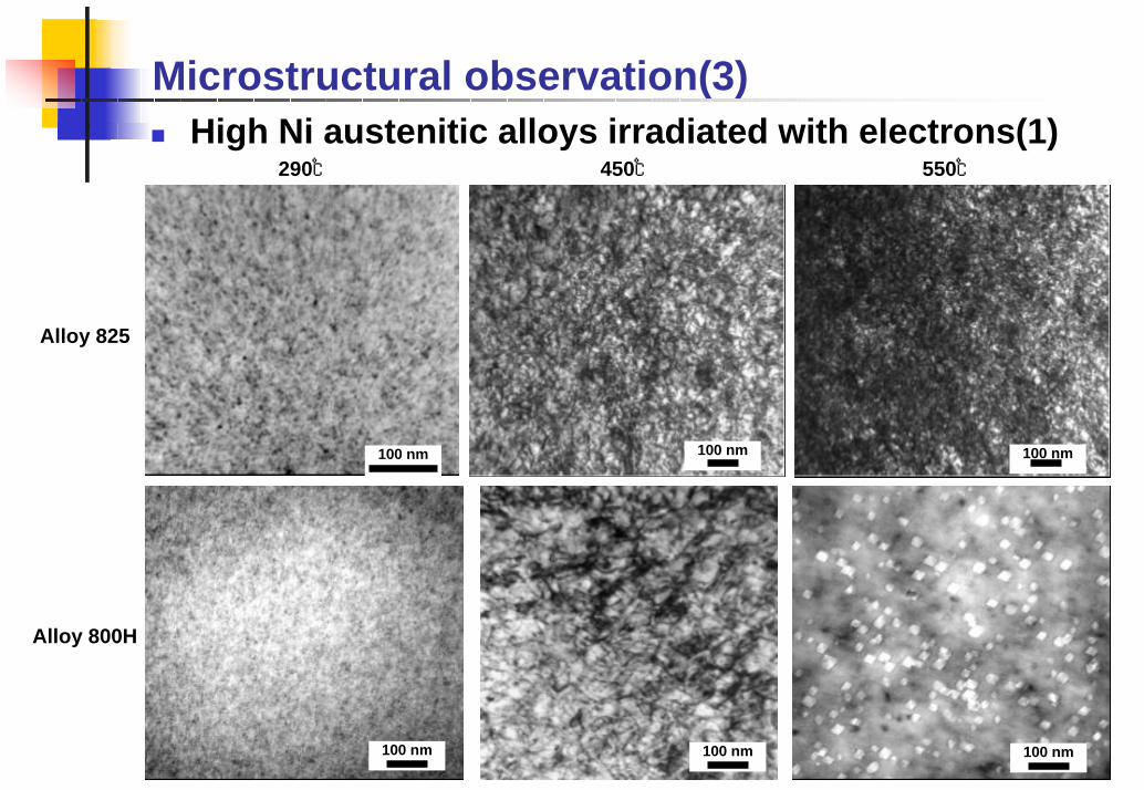
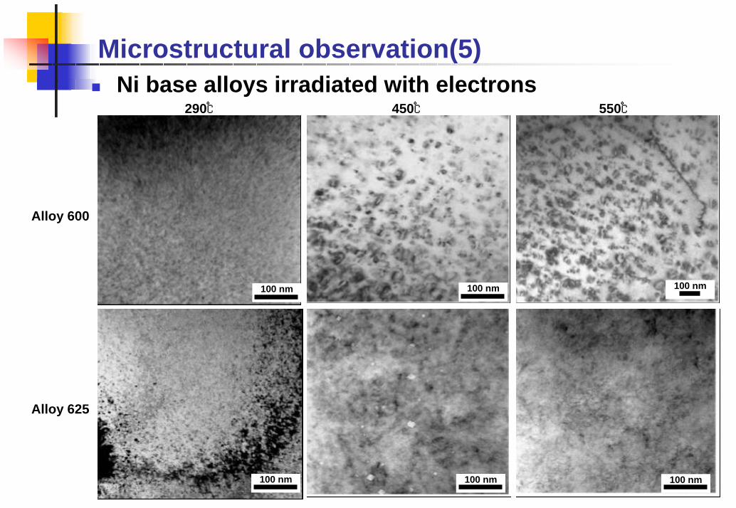
Irradiation Test (Simulation by electron irradiation)The tests have been started. The materials containing higher Ni tend to suppress the void formation.


Recommended