Device Under Test: Multiple Environmental Test: Thermal Shock, Thermal Shock MIL, Salt Fog 48 Hrs, Salt Fog 96 Hrs Physical Test: Sinusoidal Vibration, Mechanical Shock, Rotational Life, Mounting Strength, Label Adhesion Test Report Number: SP03-128 Test Start Date: October 7, 2014 Test Completion Date: December 22, 2014 Test Facility: Grayhill Inc. La Grange, IL Facility Test Requested By: Troy Naumes Test Performed By: Greg Dombrowski Laboratory Technician Report Written By: Greg Dombrowski Laboratory Technician Report Approved By: Nicole Jachna Quality Lab Manager
Transcript
Device Under Test: Multiple
Environmental Test: Thermal Shock, Thermal Shock MIL, Salt Fog 48 Hrs, Salt Fog 96 Hrs
4.1. PURPOSE The purpose for this test is to determine if the DUT can withstand the maximum torque directly applied to the nuts. 4.2. TEST SETUP DETAILS
1. Mount DUT onto a metal brackets whose hole is the recommended size for the DUT. 2. Use standard nut and lock washer for testing. 3. Use torque wrench to tighten the nut to the maximum allowable torque. 4. Inspect the DUT for any visible damage. 5. Perform functional tests after mounting. 6. Re-mount and torque nut until breakage or damage occurs and record FT-lbs.
Table 2 - Equipment List
Equipment ID Equipment Type Model Number Manufacturer Calibration Due Date
OPS Form #333, Rev A Report SP03-128 Rev. A 11/12/12
7 of 29
4.3. TEST SETUP PHOTO
Figure 1 – Mounting Torque test setup
4.4. ACCEPTANCE CRITERIA
The DUT must have no part breakage and no disassembly of parts. The DUT must be functionally tested and operate as intended after test. 4.5. TEST RESULTS There was no sign of part breakage or disassembly of parts for Max torque of 15 FT-lbs. The DUT were mechanically and electrically operative.
Table 4 – Test Results
DUT Initial
15 FT-lbs Failed FT-lbs
71A30-01-1-12N-C-NI PASS 34
51A30-01-1-10N-NI PASS 36
50A36-01-1-10N-NI PASS 36
26ASD22-01-1-AJS-NI PASS 34
56A36-01-1-10N-C-NI PASS 34
50YY50812-NI PASS 34
75BP36-01-1-10N-C-NI PASS 36
38-401-BLK PASS 30
OPS Form #333, Rev A Report SP03-128 Rev. A 11/12/12
8 of 29
5.0 SALT FOG (MIL-STD-810G, METHOD 509.4)
Test Specification DUT Part Number DUT Serial Number Test Location Test Date
5.1. PURPOSE The Salt Fog method is performed to determine the effectiveness of protective coatings and finished on materials. It may also be applied to determine the effects of salt deposits on the physical and electrical aspects of DUT. 5.2. TEST SETUP DETAILS
1. Prepare a 5 +/-1% solution by dissolving 5 parts by weight of salt in 95 parts by weight of water. 2. Adjust to and maintain the solution at a specific gravity by using the measured temperature and density of the
salt solution. 3. Maintain the pH of the salt solution between 6.5 and 7.2. 4. Set the test chamber to 35C and condition the DUT for at least 2 hours before introducing the salt fog. 5. Atomize a salt solution into the test chamber for a period of 48 hours. 6. Dry the DUT at standard ambient temperatures and a relative humidity of 50% for 24 hours. 7. Perform physical and electrical. 8. Rinse or use a gentle wash the DUT in running water and conduct the corrosion examination. 9. Perform functional test.
Table 5 – Equipment List
Equipment ID Equipment Type Model Number Manufacturer Calibration Due Date
GT-115 Salt Fog Chamber MX9204 Associated Environmental
System 04/2015
GT-401 Pressure Gauge 595-05 Ashcroft 04/2015
GT-110 PH Meter HI 98108 PHEP+ 10/2015
NA Gravity meters NA NA NA
NA Graduated Cylinders 100: 2ml Azcon NA
OPS Form #333, Rev A Report SP03-128 Rev. A 11/12/12
9 of 29
Table 6 - Test Conditions
Test Condition Units Parameters
Quantity DUT 100
Duration Hours 48
Salt Solution parts 5 ± 1 parts per 95 parts water by mass
Type of Water Distilled or De-ionized water
Duration hours 96
pH Levels 6.5 to 7.2
Temperature °C 35
Volume of solution measured per hour
mL 1.0 to 2.0 mL
5.3. TEST SETUP PHOTOS
Figure 2– Salt Fog Test Setup
OPS Form #333, Rev A Report SP03-128 Rev. A 11/12/12
10 of 29
Figure 3– DUT after 48 hours Salt Fog and 24 hours drying
(STD plating on the left and NI plating on the right)
5.4. ACCEPTANCE CRITERIA The DUT shall satisfactorily withstand the salt fog conditions specified without physical damage. The DUT shall be fully functional after the test. 5.5. TEST RESULTS There was no visible corrosion, seal break down, or material breakdown on any DUT. The DUT exhibited normal posttest operation.
OPS Form #333, Rev A Report SP03-128 Rev. A 11/12/12
11 of 29
Table 7 – Test Results
DUT Test Specification Pass Test Location Test Date
71A30-01-1-12N-C-NI Salt Fog 48 Hrs MIL-STD-810G Method 509.4
PASS Grayhill Inc. 10/07/2014 – 10/09/2014
77P36-01-1-10N-NI Salt Fog 48 Hrs MIL-STD-810G Method 509.4
PASS Grayhill Inc. 10/07/2014 – 10/09/2014
51A30-01-1-10N-NI Salt Fog 48 Hrs MIL-STD-810G Method 509.4
PASS Grayhill Inc. 10/07/2014 – 10/09/2014
50A36-01-1-10N-NI Salt Fog 48 Hrs MIL-STD-810G Method 509.4
PASS Grayhill Inc. 10/07/2014 – 10/09/2014
26ASD22-01-1-AJS-NI Salt Fog 48 Hrs MIL-STD-810G Method 509.4
PASS Grayhill Inc. 10/07/2014 – 10/09/2014
56A36-01-1-10N-C-NI Salt Fog 48 Hrs MIL-STD-810G Method 509.4
PASS Grayhill Inc. 10/07/2014 – 10/09/2014
50YY50812-NI Salt Fog 48 Hrs MIL-STD-810G Method 509.4
PASS Grayhill Inc. 10/07/2014 – 10/09/2014
75BP36-01-1-10N-C-NI Salt Fog 48 Hrs MIL-STD-810G Method 509.4
PASS Grayhill Inc. 10/07/2014 – 10/09/2014
75AY23083-NI Salt Fog 48 Hrs MIL-STD-810G Method 509.4
PASS Grayhill Inc. 10/07/2014 – 10/09/2014
38-401-BLK Salt Fog 48 Hrs MIL-STD-810G Method 509.4
PASS Grayhill Inc. 10/07/2014 – 10/09/2014
OPS Form #333, Rev A Report SP03-128 Rev. A 11/12/12
12 of 29
6.0 SALT FOG 96 Hrs (MIL-STD-810G, METHOD 509.4)
Test Specification DUT Part Number DUT Serial Number Test Location Test Date
6.1. PURPOSE The Salt Fog method is performed to determine the effectiveness of protective coatings and finished on materials. It may also be applied to determine the effects of salt deposits on the physical and electrical aspects of DUT. 6.2. TEST SETUP DETAILS
1. Prepare a 5 +/-1% solution by dissolving 5 parts by weight of salt in 95 parts by weight of water. 2. Adjust to and maintain the solution at a specific gravity by using the measured temperature and density of the
salt solution. 3. Maintain the pH of the salt solution between 6.5 and 7.2. 4. Set the test chamber to 35C and condition the DUT for at least 2 hours before introducing the salt fog. 5. Atomize a salt solution into the test chamber for a period of 96 hours. 6. Dry the DUT at standard ambient temperatures and a relative humidity of 50% for 24 hours. 7. Perform physical and electrical. 8. Rinse or use a gentle wash the DUT in running water and conduct the corrosion examination. 9. Perform functional test.
Table 8 – Equipment List
Equipment ID Equipment Type Model Number Manufacturer Calibration Due Date
GT-115
Salt Fog Chamber
MX9204
Associated Environmental System
04/2015
GT-401 Pressure Gauge 595-05 Ashcroft 04/2015
GT-110 PH Meter HI 98108 PHEP+ 10/2015
NA Gravity meters NA NA NA
NA Graduated Cylinders 100: 2ml Azcon NA
OPS Form #333, Rev A Report SP03-128 Rev. A 11/12/12
13 of 29
Table 9 - Test Conditions
Test Condition Units Parameters
Quantity DUT 100
Duration Hours 96
Salt Solution parts 5 ± 1 parts per 95 parts water by mass
Type of Water Distilled or De-ionized water
Duration hours 96
pH Levels 6.5 to 7.2
Temperature °C 35
Volume of solution measured per hour
mL 1.0 to 2.0 mL
6.3. TEST SETUP PHOTOS
Figure 4– Salt Fog Test Setup
OPS Form #333, Rev A Report SP03-128 Rev. A 11/12/12
14 of 29
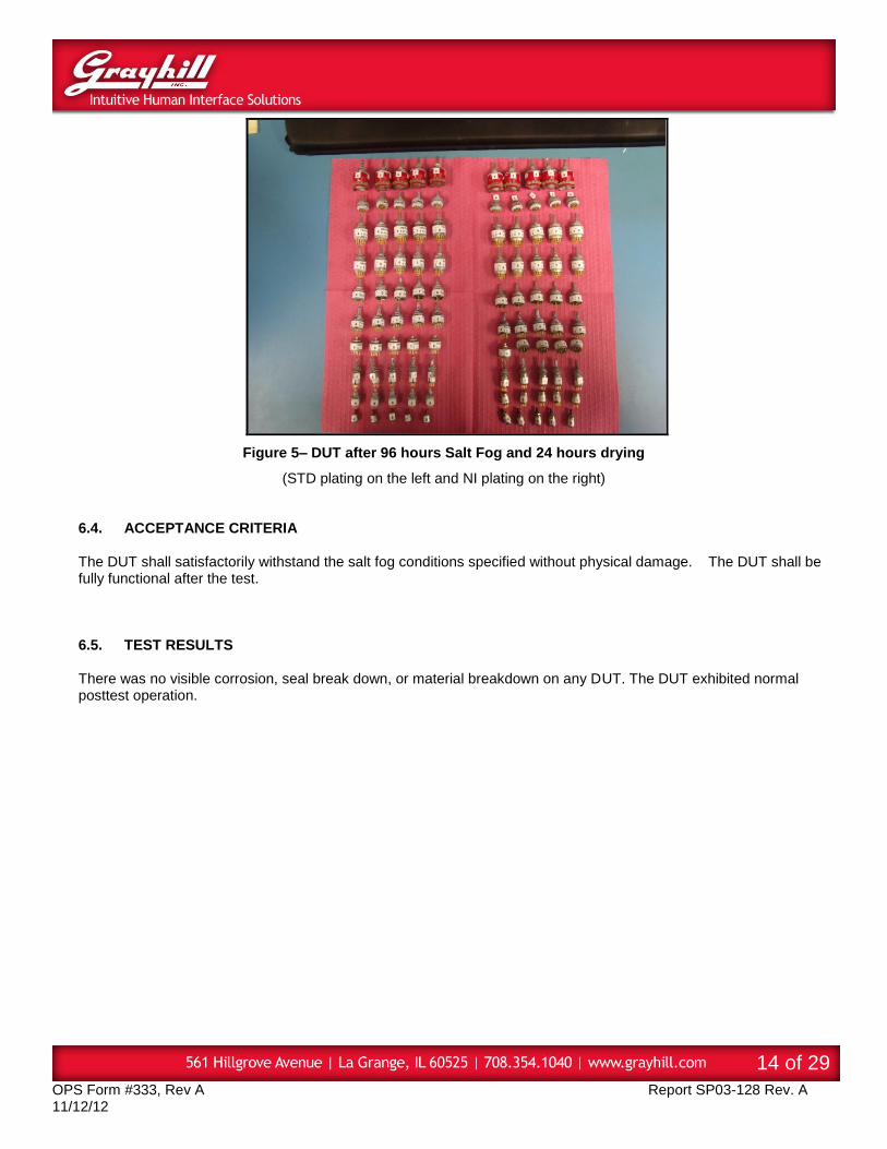
Figure 5– DUT after 96 hours Salt Fog and 24 hours drying
(STD plating on the left and NI plating on the right) 6.4. ACCEPTANCE CRITERIA The DUT shall satisfactorily withstand the salt fog conditions specified without physical damage. The DUT shall be fully functional after the test.
6.5. TEST RESULTS There was no visible corrosion, seal break down, or material breakdown on any DUT. The DUT exhibited normal posttest operation.
OPS Form #333, Rev A Report SP03-128 Rev. A 11/12/12
15 of 29
Table 10 – Test Results
DUT Test Specification Pass Test Location Test Date
71A30-01-1-12N-C-NI Salt Fog 96 Hrs MIL-STD-810G Method 509.4
PASS Grayhill Inc. 10/07/2014 – 10/11/2014
77P36-01-1-10N-NI Salt Fog 96 Hrs MIL-STD-810G Method 509.4
PASS Grayhill Inc. 10/07/2014 – 10/11/2014
51A30-01-1-10N-NI Salt Fog 96 Hrs MIL-STD-810G Method 509.4
PASS Grayhill Inc. 10/07/2014 – 10/11/2014
50A36-01-1-10N-NI Salt Fog 96 Hrs MIL-STD-810G Method 509.4
PASS Grayhill Inc. 10/07/2014 – 10/11/2014
26ASD22-01-1-AJS-NI Salt Fog 96 Hrs MIL-STD-810G Method 509.4
PASS Grayhill Inc. 10/07/2014 – 10/11/2014
56A36-01-1-10N-C-NI Salt Fog 96 Hrs MIL-STD-810G Method 509.4
PASS Grayhill Inc. 10/07/2014 – 10/11/2014
50YY50812-NI Salt Fog 96 Hrs MIL-STD-810G Method 509.4
PASS Grayhill Inc. 10/07/2014 – 10/11/2014
75BP36-01-1-10N-C-NI Salt Fog 96 Hrs MIL-STD-810G Method 509.4
PASS Grayhill Inc. 10/07/2014 – 10/11/2014
75AY23083-NI Salt Fog 96 Hrs MIL-STD-810G Method 509.4
PASS Grayhill Inc. 10/07/2014 – 10/11/2014
38-401-BLK Salt Fog 96 Hrs MIL-STD-810G Method 509.4
PASS Grayhill Inc. 10/07/2014 – 10/11/2014
OPS Form #333, Rev A Report SP03-128 Rev. A 11/12/12
16 of 29
7.0 SINUSOIDAL VIBRATION TEST
Test Specification DUT Part Number DUT Serial Number Test Location Test Date
7.1. PURPOSE The purpose of this test is to evaluate the DUT of its ability to withstand sinusoidal vibration. The potential product failure modes and effects detected in this test are: • Cracked housing/components • Broken product/components • Open solder joints • Dislodged parts • Loose mounting interfaces. 7.2. TEST SETUP DETAILS
Test Profile and Setup Details:
1. Visual Inspection of the DUT is to be performed before and after testing 2. Attach characterization sample(s) to the test fixture on the test table in specified orientation. 3. Characterize set-up conditions. 4. Attach DUT in specified orientation. 5. Attach connector(s) and tie down wire harness(es) at appropriate lengths, if required. 6. Power and monitor DUT output. 7. Apply vibration, temperature and voltage per specified levels and verify operation, if required. 8. Vibrate the DUT for specified duration. 9. Subject DUT to conditions in Test Checkpoint Table. 10. Repeat steps D thru I until all DUT have been tested for their total duration. 11. Perform the Visual Examination and Functional Check after the test.
Table 11 – Equipment List
Equipment ID Equipment Type Model Number Manufacturer Calibration Due Date
GT-353 Shaker Table DS-11000VH/1.7-50 Dynamic Solutions Calibration Not Required
GT-354 Shaker Table
Amplifier SA-50 Dynamic Solutions Calibration Not Required
GT-355 Shaker Table
Controller DVC-8 Vibration World 05/2015
GT-535 Shear
Accelerometer JTLD352C04 PCB Piezotronics 10/2015
OPS Form #333, Rev A Report SP03-128 Rev. A 11/12/12
17 of 29
Table 12 - Test Condition
Test Condition Units Parameters
Quantity DUT 170
Duration Hours 2 per axis
Operational Mode Volts Monitored with Chatterbox
Applicable Axes 3 Longitudinal, Transverse, and Vertical
Temperature C Ambient
Lower Limit Frequency Hz 10
Upper Limit Frequency Hz 55
Sweep Rate Min./Cycle 1
Pass/Fail Criteria See below
Table 13 – Profile Break Points
Frequency (Hz) Displacement (th)
10 60
55 60
7.3. TEST SETUP PHOTOS
Figure 6 – Sinusoidal Vibration for DUT being monitored.
OPS Form #333, Rev A Report SP03-128 Rev. A 11/12/12
18 of 29
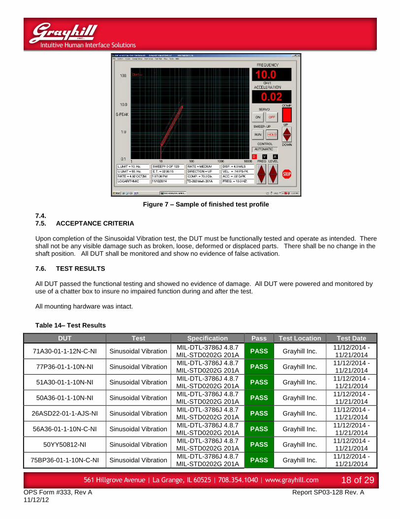
Figure 7 – Sample of finished test profile
7.4. 7.5. ACCEPTANCE CRITERIA Upon completion of the Sinusoidal Vibration test, the DUT must be functionally tested and operate as intended. There shall not be any visible damage such as broken, loose, deformed or displaced parts. There shall be no change in the shaft position. All DUT shall be monitored and show no evidence of false activation. 7.6. TEST RESULTS All DUT passed the functional testing and showed no evidence of damage. All DUT were powered and monitored by use of a chatter box to insure no impaired function during and after the test. All mounting hardware was intact.
Table 14– Test Results
DUT Test Specification Pass Test Location Test Date
8.1. PURPOSE The purpose of this test is to validate the manufacturing process in its ability to produce a product capable of withstanding the effects of shipping, handling, installation, and operational shock. The potential product issue modes and effects detected in this test are: • Housing cracks • Product/component breakage • Inadvertent activation 8.2. TEST SETUP DETAILS
1. Visual Inspection of the DUT is to be performed before and after testing. 2. Verify specified test conditions table with test fixture on test table. 3. Place product in a holding fixture in specified orientation. 4. Attach connector(s) and tie down wire harness at appropriate lengths, if required. 5. Monitor DUT outputs, if required. 6. Test product for specified shocks/axis. 7. Repeat until all DUT have completed their total shocks/unit. 8. Perform the Visual Examination and Functional Check after the test.
Table 15 – Equipment List
Equipment ID Equipment Type Model Number Manufacturer Calibration Due Date
OPS Form #333, Rev A Report SP03-128 Rev. A 11/12/12
20 of 29
Table 16 - Test Conditions
Test Condition Units Parameters
Quantity DUT 170
Operational Mode Unpowered / Chatter Box
Pulse Type Saw Tooth
Acceleration G 100
Pulse duration ‘msec. 6
Drops per/axis 3
Direction 3 in each of +/-X, +/-Y, +/-Z (18 shocks total)
8.3. TEST SETUP PHOTOS
Figure 8– Mechanical Shock Test Setup
Figure 9 – Mechanical Shock Test Monitoring
OPS Form #333, Rev A Report SP03-128 Rev. A 11/12/12
21 of 29
Figure 10 – Mechanical Shock Wave Form
8.4. ACCEPTANCE CRITERIA
As MIL-DTL-3786J states, any pair of mating switch section contacts shall not open for a period of time longer
than 10 µs unless otherwise specified. After the test, there shall be no change in shaft position, or evidence of
broken, loose, deformed, or displaced parts.
8.5. TEST RESULTS Functional status was verified by monitoring DUT with a Chatter Box during testing. After testing there was no change in shaft position, no evidence of broken, loose, deformed or displaced parts. All DUT passed the functional testing.
Table 17 – Test Results
DUT Test Specification Pass Test Location Test Date
9.1. PURPOSE This test was conducted for the purpose of determining the resistance of DUT from sudden changes in the temperature of the surrounding atmosphere without experiencing physical, mechanical, and electrical damage or deterioration in performance. 9.2. TEST SETUP DETAILS
1. Visual examination of the test item with special attention to stress areas such as corners of molded housing and document the results.
2. Take picture of the test item. 3. Set Temperature Chamber as specified in the test plan for thermal shock. 4. Maintain the thermal shock temperature for a period as specified in the test plan. 5. Adjust Temperature Chamber to standard ambient and maintain until the test item has achieved temperature
stabilization. 6. Conduct a complete visual examination of the test item and document the results. 7. Compare these data with the initial visual examination. 8. Perform functional check on the test item.
Table 18 – Equipment List
Equipment ID Equipment Type Model Number Manufacturer Calibration Due Date
GT- 1008 Thermal Shock VTS-3-6-6-SC/WC Cincinnati Sub Zero 10/2015
GT-542 Thermometer EasyView 15 Extech 08/2015
Table 19 - Test Conditions
Test Condition Units Parameters
Quantity DUT 170
Duration Cycles 5
Dwell Time Hours Or Minute
1 Hour
Transfer time Minute 1
Operational Mode Unpowered
Minimum Temperature C -65
Maximum Temperature C 85
OPS Form #333, Rev A Report SP03-128 Rev. A 11/12/12
23 of 29
9.3. TEST SETUP PHOTOS
Figure 11 – Thermal Shock Test Setup
9.4. ACCEPTANCE CRITERIA Upon completion of the Thermal Shock Test, DUT contact resistance shall not exceed 500 milliohms, and there shall
be no mechanical or electrical damage, loosing of rivets, or other fastening devices.
9.5. TEST RESULTS DUT contact resistance did not exceed 500 milliohms. There was not any evidence of damage to DUT housing and shaft.
Table 20 – Test Results
DUT Test Specification Pass Test Location Test Date
71A30-01-1-12N-C-NI Thermal Shock MIL-STD-202G
107G PASS Grayhill Inc. 12/19/2014
77P36-01-1-10N-NI Thermal Shock MIL-STD-202G
107G PASS Grayhill Inc. 12/19/2014
51A30-01-1-10N-NI Thermal Shock MIL-STD-202G
107G PASS Grayhill Inc. 12/19/2014
50A36-01-1-10N-NI Thermal Shock MIL-STD-202G
107G PASS Grayhill Inc. 12/19/2014
26ASD22-01-1-AJS-NI Thermal Shock MIL-STD-202G
107G PASS Grayhill Inc. 12/19/2014
56A36-01-1-10N-C-NI Thermal Shock MIL-STD-202G
107G PASS Grayhill Inc. 12/19/2014
50YY50812-NI Thermal Shock MIL-STD-202G
107G PASS Grayhill Inc. 12/19/2014
75BP36-01-1-10N-C-NI Thermal Shock MIL-STD-202G
107G PASS Grayhill Inc. 12/19/2014
OPS Form #333, Rev A Report SP03-128 Rev. A 11/12/12
24 of 29
10.0 ROTATIONAL LIFE
Test Specification DUT Part Number DUT Test Location Test Date
10.1. PURPOSE The purpose of this test is to determine the ability of DUT to operate satisfactorily under simultaneously applied varying conditions of high / low temperature. 10.2. TEST SETUP DETAILS
1. Visual Inspection of the DUT is to be performed before and after testing 2. Measure and record the Initial torque values. 3. Program the Rotational Life Tester at 20RPM for 25000 cycles. 4. The cycle rate was approximately 10 cycles per minute. 5. Mount DUT onto Rotational Life Tester. 6. After 25000 cycles, measure and record Torque.
Table 21 – Equipment List
Equipment ID Equipment Type Model Number Manufacturer Calibration Due Date
OPS Form #333, Rev A Report SP03-128 Rev. A 11/12/12
25 of 29
Table 22 - Test Conditions
Test Condition Units Parameters
Quantity Assemblies 170
Operational Mode Unpowered
Test Temperature °C 24.6
Humidity %Rh 26.1
Cycle Rate RPM 20
10.3. TEST SETUP PHOTOS
Figure 12 – Rotational Life Test Setup
10.4. ACCEPTANCE CRITERIA
The DUT must function normally before, during, and after the Rotational Life Tests. There shall be no mechanical damage, loosening of rivets or other fastening devices. The rotational torque shall be in between 0.5 in-lbs and 1.5 in-lbs.
10.5. TEST RESULTS
There was no evidence of any electrical, physical, or mechanical damage. All DUT were function normally after the Rotational Life Tests.
Table 23 – Test Results
DUT Test Specification Pass Test Location Test Date
71A30-01-1-12N-C-NI Rotational Life MIL-DTL-3786J PASS Grayhill Inc. 10/27/2014 – 12/11/2014
77P36-01-1-10N-NI Rotational Life MIL-DTL-3786J PASS Grayhill Inc. 10/27/2014 – 12/11/2014
50A36-01-1-10N-NI Rotational Life MIL-DTL-3786J PASS Grayhill Inc. 10/27/2014 – 12/11/2014
26ASD22-01-1-AJS-NI Rotational Life MIL-DTL-3786J PASS Grayhill Inc. 10/27/2014 – 12/11/2014
56A36-01-1-10N-C-NI Rotational Life MIL-DTL-3786J PASS Grayhill Inc. 10/27/2014 – 12/11/2014
50YY50812-NI Rotational Life MIL-DTL-3786J PASS Grayhill Inc. 10/27/2014 – 12/11/2014
75BP36-01-1-10N-C-NI Rotational Life MIL-DTL-3786J PASS Grayhill Inc. 10/27/2014 – 12/11/2014
OPS Form #333, Rev A Report SP03-128 Rev. A 11/12/12
26 of 29
11.0 ROTATIONAL LIFE AT TEMPERATURE
Test Specification DUT Part Number DUT Test Location Test Date
11.1. PURPOSE The purpose of this test is to determine the ability of DUT to operate satisfactorily under simultaneously applied varying conditions of high / low temperature. 11.2. TEST SETUP DETAILS
1. Visual Inspection of the DUT is to be performed before and after testing 2. Measure and record the Initial torque values. 3. Program the Rotational Life Tester at 20RPM for 25000 cycles. 4. The cycle rate was approximately 10 cycles per minute. 5. Mount DUT onto Rotational Life Tester. 6. After 25000 cycles, measure and record Torque.
Table 24 – Equipment List
Equipment ID Equipment Type Model Number Manufacturer Calibration Due Date
OPS Form #333, Rev A Report SP03-128 Rev. A 11/12/12
27 of 29
Table 25 - Test Conditions
Test Condition Units Parameters
Quantity Assemblies 85
Operational Mode Unpowered
Test Temperature °C 85
Duration Cycles 25,000
Cycle Rate RPM 20
11.3. ACCEPTANCE CRITERIA The DUT must function normally before, during, and after the Rotational Life Tests. There shall be no mechanical damage, loosening of rivets or other fastening devices. The rotational torque shall be in between 0.5 in-oz and 1.5 in-oz. 11.4. TEST RESULTS There was no evidence of any electrical, physical, or mechanical damage. DUT function normally after the Rotational Life Tests
Table 26 – Test Results
DUT Test Specification Pass Test Location Test Date
71A30-01-1-12N-C-NI Rotational Life MIL-DTL-3786J PASS Grayhill Inc. 11/21/14 – 12/08/14
77P36-01-1-10N-NI Rotational Life MIL-DTL-3786J PASS Grayhill Inc. 11/21/14 – 12/08/14
50A36-01-1-10N-NI Rotational Life MIL-DTL-3786J PASS Grayhill Inc. 11/21/14 – 12/08/14
26ASD22-01-1-AJS-NI Rotational Life MIL-DTL-3786J PASS Grayhill Inc. 11/21/14 – 12/08/14
56A36-01-1-10N-C-NI Rotational Life MIL-DTL-3786J PASS Grayhill Inc. 11/21/14 – 12/08/14
50YY50812-NI Rotational Life MIL-DTL-3786J PASS Grayhill Inc. 11/21/14 – 12/08/14
75BP36-01-1-10N-C-NI Rotational Life MIL-DTL-3786J PASS Grayhill Inc. 11/21/14 – 12/08/14
OPS Form #333, Rev A Report SP03-128 Rev. A 11/12/12
28 of 29
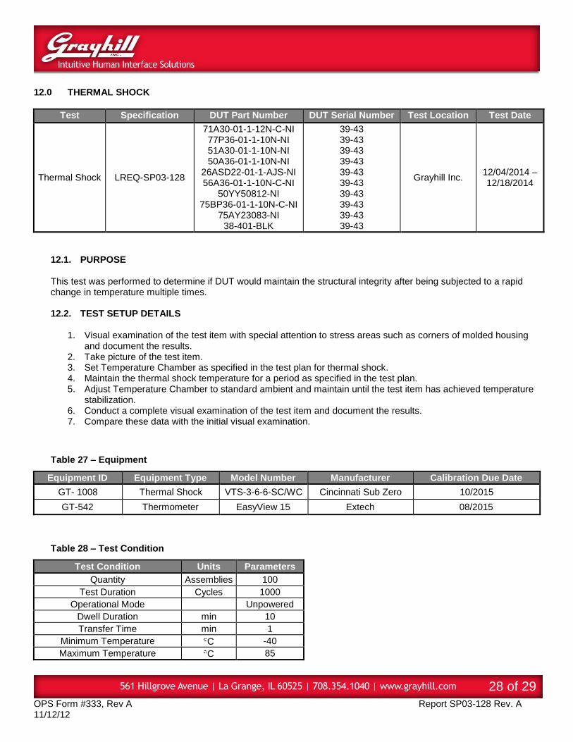
12.0 THERMAL SHOCK
Test Specification DUT Part Number DUT Serial Number Test Location Test Date
12.1. PURPOSE This test was performed to determine if DUT would maintain the structural integrity after being subjected to a rapid change in temperature multiple times. 12.2. TEST SETUP DETAILS
1. Visual examination of the test item with special attention to stress areas such as corners of molded housing and document the results.
2. Take picture of the test item. 3. Set Temperature Chamber as specified in the test plan for thermal shock. 4. Maintain the thermal shock temperature for a period as specified in the test plan. 5. Adjust Temperature Chamber to standard ambient and maintain until the test item has achieved temperature
stabilization. 6. Conduct a complete visual examination of the test item and document the results. 7. Compare these data with the initial visual examination.
Table 27 – Equipment
Equipment ID Equipment Type Model Number Manufacturer Calibration Due Date
GT- 1008 Thermal Shock VTS-3-6-6-SC/WC Cincinnati Sub Zero 10/2015
GT-542 Thermometer EasyView 15 Extech 08/2015
Table 28 – Test Condition
Test Condition Units Parameters
Quantity Assemblies 100
Test Duration Cycles 1000
Operational Mode Unpowered
Dwell Duration min 10
Transfer Time min 1
Minimum Temperature C -40
Maximum Temperature C 85
OPS Form #333, Rev A Report SP03-128 Rev. A 11/12/12
29 of 29
12.3. TEST SETUP PHOTOS
Figure 13 – Thermal Shock Setup
12.4. ACCEPTANCE CRITERIA Upon completion of the Thermal Shock Test, there shall not be any visible damage or tin whiskers to DUT. 12.5. TEST RESULTS
There was no physical damage to the NI plated DUT after completing the test.
Table 29 – Test Results
DUT Test Specification Pass Test Location Test Date
71A30-01-1-12N-C-NI Thermal Shock Grayhill Custom PASS Grayhill Inc. 12/04/2014 -12/18/2014
77P36-01-1-10N-NI Thermal Shock Grayhill Custom PASS Grayhill Inc. 12/04/2014 -12/18/2014
51A30-01-1-10N-NI Thermal Shock Grayhill Custom PASS Grayhill Inc. 12/04/2014 -12/18/2014
50A36-01-1-10N-NI Thermal Shock Grayhill Custom PASS Grayhill Inc. 12/04/2014 -12/18/2014
26ASD22-01-1-AJS-NI Thermal Shock Grayhill Custom PASS Grayhill Inc. 12/04/2014 -12/18/2014
56A36-01-1-10N-C-NI Thermal Shock Grayhill Custom PASS Grayhill Inc. 12/04/2014 -12/18/2014
50YY50812-NI Thermal Shock Grayhill Custom PASS Grayhill Inc. 12/04/2014 -12/18/2014
75BP36-01-1-10N-C-NI Thermal Shock Grayhill Custom PASS Grayhill Inc. 12/04/2014 -12/18/2014
75AY23083-NI Thermal Shock Grayhill Custom PASS Grayhill Inc. 12/04/2014 -12/18/2014
38-401-BLK Thermal Shock Grayhill Custom PASS Grayhill Inc. 12/04/2014 -12/18/2014