Use, duplication or disclosure of this document or any of the information contained herein is subject to the restrictions established on page ii of this document.
5136-DN/5136-DNPDeviceNet Scanner Module / 32-Bit DLL API
Use, duplication or disclosure of this document or any of the information contained herein is subject to the restrictions established on page ii of this document.
Use, duplication or disclosure of this document or any of the information contained herein is subject to the restrictions established on page ii of this document.
Use, duplication or disclosure of this document or any of the information contained herein is subject to the restrictions established on page ii of this document.
Revision History
VERSION DATE PAGE-PARAGRAPH REMARKS
2.21 30 May 2002 All Manual officially released
715-0024 v 2.21 CCB # 29 DN Scanner Module / 32-Bit DLL API Ref Guide
Use, duplication or disclosure of this document or any of the information contained herein is subject to the restrictions established on page ii of this document.
Table Of Contents
1 Introduction 1 1.1 Purpose of this Document 1 1.2 The DeviceNet Scanner Module 1 1.3 Distribution Files 2
2 DeviceNet Compliance Statement 3 2.1 Introduction 3 2.2 Conformance Test Statement 3 2.3 Specification Revision 3 2.4 General Communication Capabilities 3
2.4.1 Data Rate 3 2.4.2 Predefined Master/Slave Connection Set 3 2.4.3 Dynamic Connections 3 2.4.4 Fragmentation 4
2.5 Identity Object 4 2.5.2 Class Attributes 4 2.5.3 Class Services 4 2.5.4 Instance Attributes 4 2.5.5 Instance Services 5
3.3.1 Application Module Header 14 3.3.2 Command Buffer 14 3.3.3 Client Status Block 14 3.3.4 Client Control Block 14 3.3.5 Server Status Block 14 3.3.6 Server Control Block 14 3.3.7 Device Control Event Table 15 3.3.8 Device Status Table 15 3.3.9 Device Control Table 15 3.3.10 Memory Pool 15
3.4 Server Configuration 15 3.4.1 Server Connection Configuration 16
715-0024 v 2.21 CCB # 29 DN Scanner Module / 32-Bit DLL API Ref Guide
Use, duplication or disclosure of this document or any of the information contained herein is subject to the restrictions established on page ii of this document.
Use, duplication or disclosure of this document or any of the information contained herein is subject to the restrictions established on page ii of this document.
4.8.1 Server Status Block 56 4.8.2 Status Code 56 4.8.3 Status Flags 57 4.8.4 I/O Event Flags 57 4.8.5 Explicit Request Event Flags 57 4.8.6 Explicit Response Event Flags 58 4.8.7 Allocated G2 Connection Flags 58
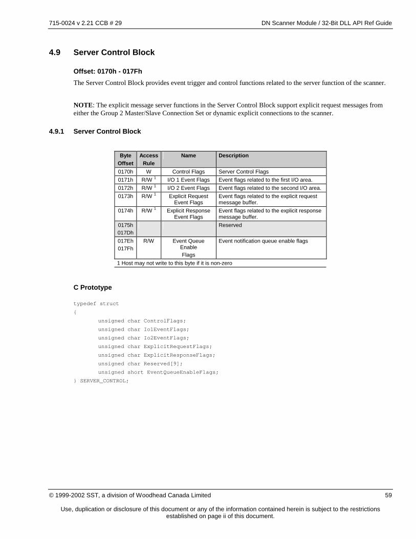
4.9 Server Control Block 59 4.9.1 Server Control Block 59 4.9.2 Control Flags 60 4.9.3 I/O Event Flags 60 4.9.4 Explicit Request Event Flags 60 4.9.5 Explicit Response Event Flags 61 4.9.6 Event Queue Enable Flags 61
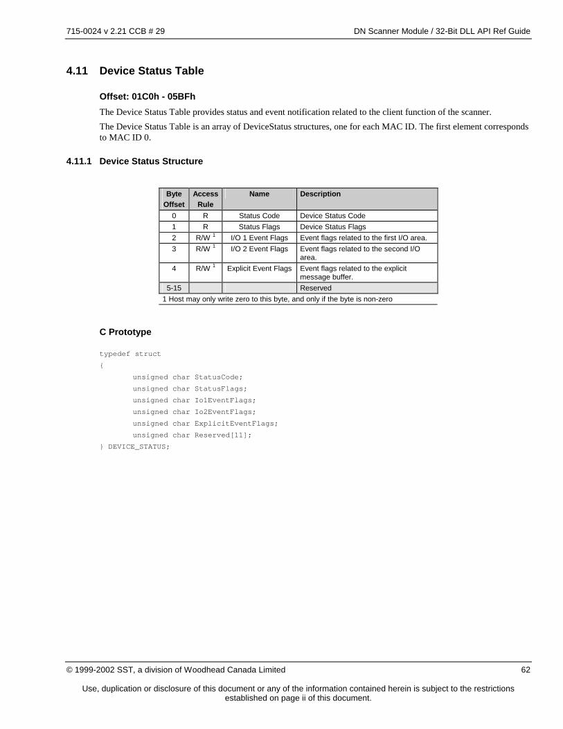
4.10 Device Control Event Table 61 4.11 Device Status Table 62
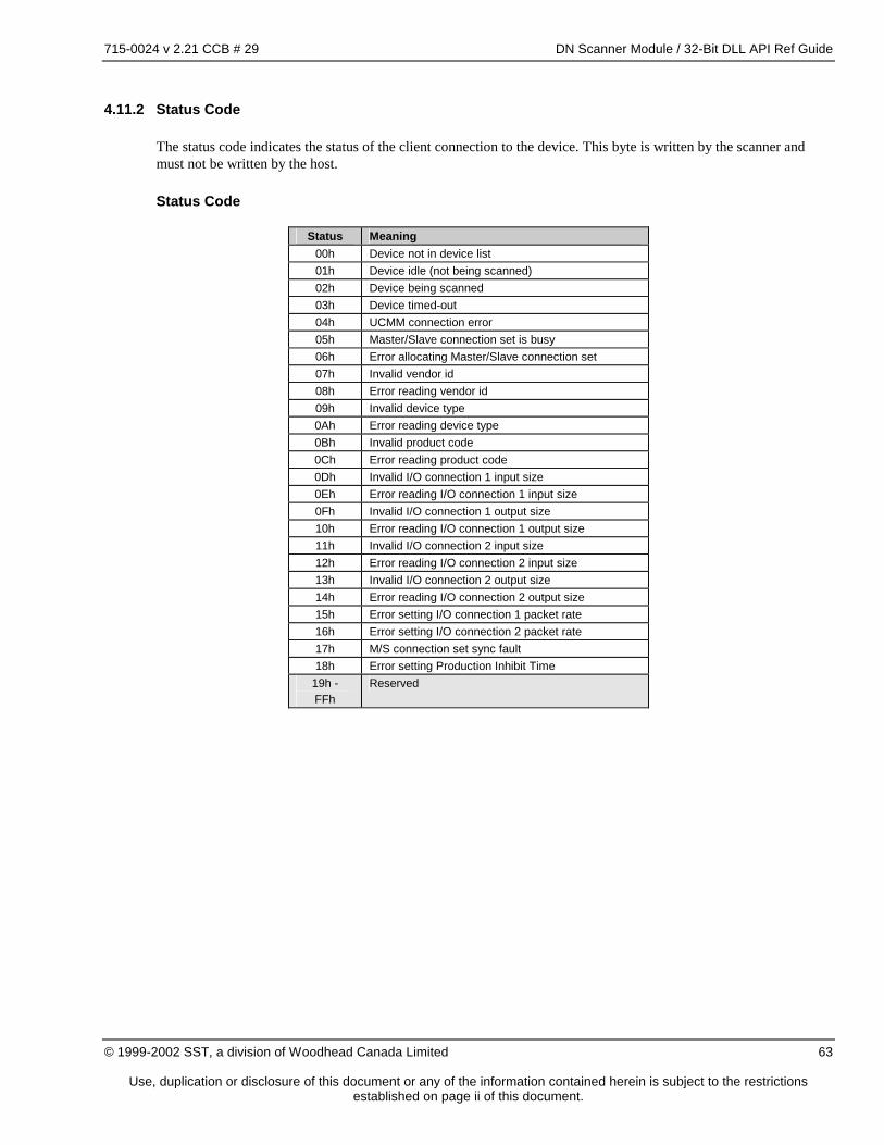
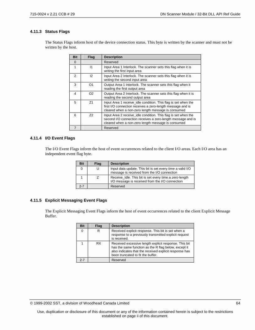
4.11.1 Device Status Structure 62 4.11.2 Status Code 63 4.11.3 Status Flags 64 4.11.4 I/O Event Flags 64 4.11.5 Explicit Messaging Event Flags 64
Use, duplication or disclosure of this document or any of the information contained herein is subject to the restrictions established on page ii of this document.
Use, duplication or disclosure of this document or any of the information contained herein is subject to the restrictions established on page ii of this document.
Use, duplication or disclosure of this document or any of the information contained herein is subject to the restrictions established on page ii of this document.
1 Introduction
1.1 Purpose of this Document
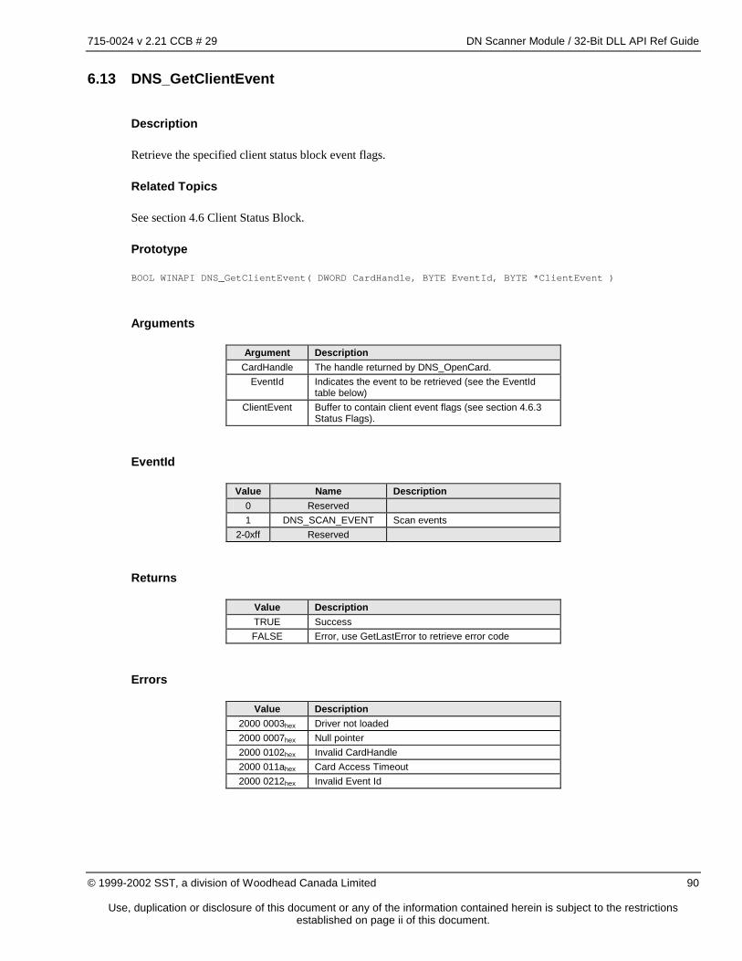
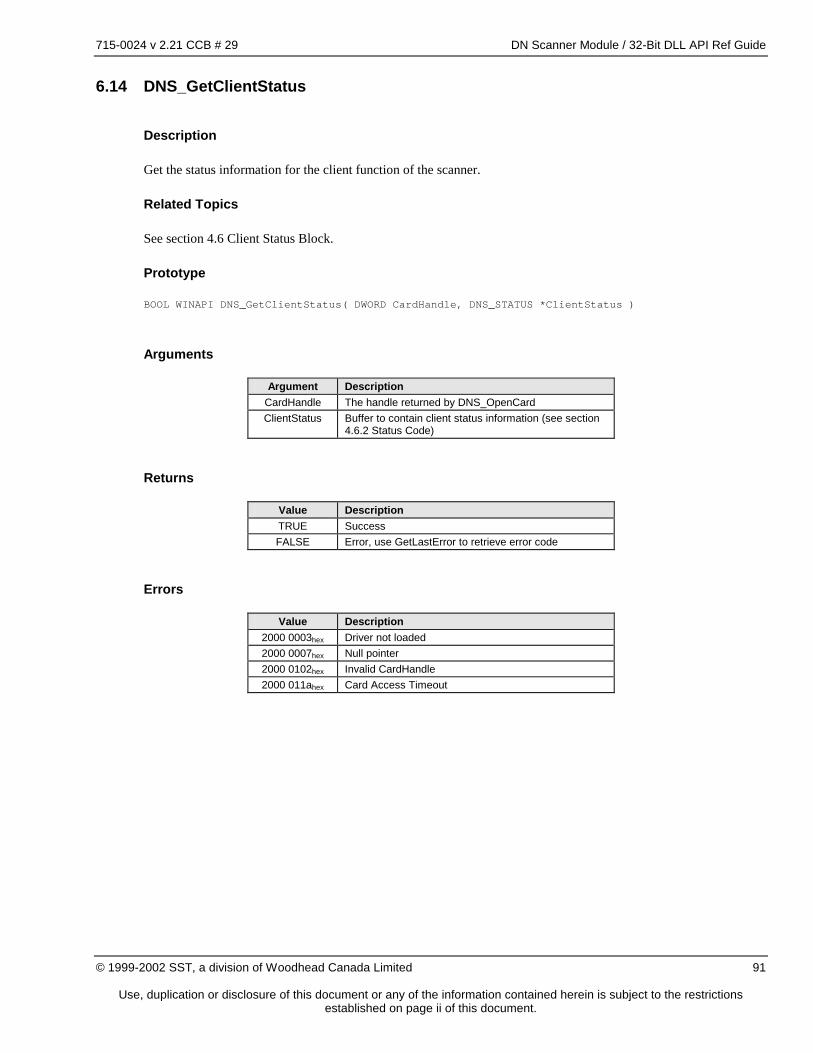
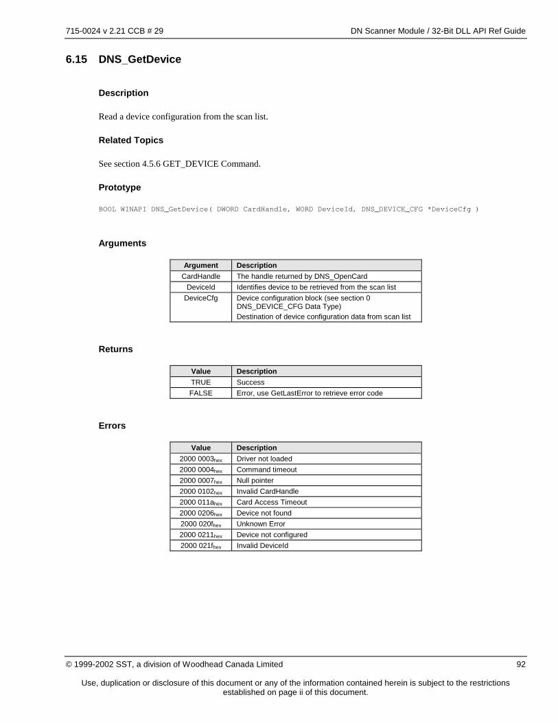
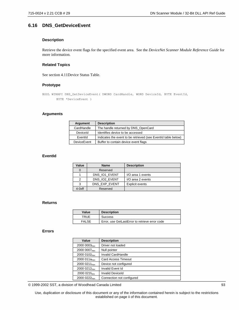
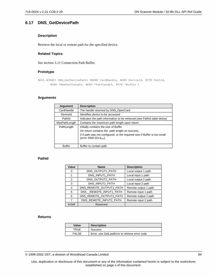
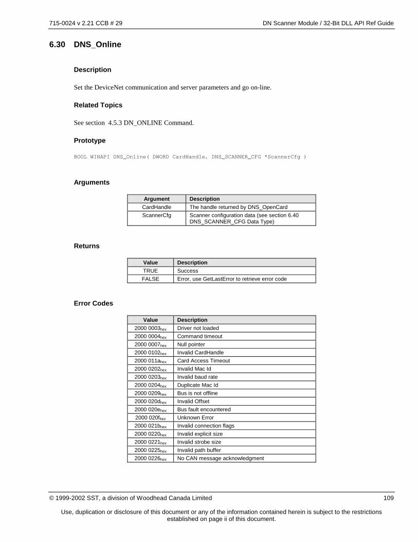
This document is a reference guide for the DeviceNet Scanner Module (DNSCAN), an application module for the 5136-DN and 5136-DNP family of interface cards.
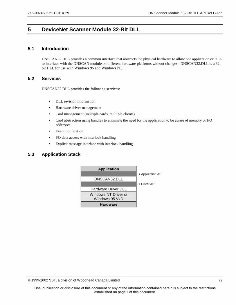
1.2 The DeviceNet Scanner Module
The DeviceNet Scanner Module is a node on the DeviceNet network. It administers the exchange of I/O data between the host system and devices on the DeviceNet network. The DeviceNet Scanner Module:
• Manages all network communication without intervention by the host system
• Provides a high-speed memory-mapped interface for I/O data exchange General capabilities:
Use, duplication or disclosure of this document or any of the information contained herein is subject to the restrictions established on page ii of this document.
1.3 Distribution Files
DNSCAN.SS1
This file is an encoded version of the SST DeviceNet Scanner module firmware for use with the SST DN Family of DeviceNet interface cards.
DNSCAN.SS2
This file is an encoded version of the SST DeviceNet Scanner module firmware for use with the SST DNP Family of DeviceNet interface cards.
DNSCAN.BIN
This file is a binary image release file for use with the SST Family of DeviceNet interface cards.
715-0024 v 2.21 CCB # 29 DN Scanner Module / 32-Bit DLL API Ref Guide
Use, duplication or disclosure of this document or any of the information contained herein is subject to the restrictions established on page ii of this document.
2 DeviceNet Compliance Statement
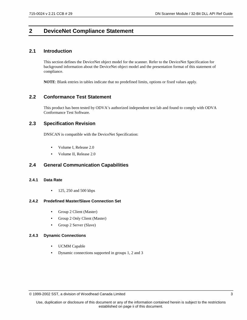
2.1 Introduction
This section defines the DeviceNet object model for the scanner. Refer to the DeviceNet Specification for background information about the DeviceNet object model and the presentation format of this statement of compliance.
NOTE: Blank entries in tables indicate that no predefined limits, options or fixed values apply.
2.2 Conformance Test Statement
This product has been tested by ODVA’s authorized independent test lab and found to comply with ODVA Conformance Test Software.
2.3 Specification Revision
DNSCAN is compatible with the DeviceNet Specification:
• Volume I, Release 2.0
• Volume II, Release 2.0
2.4 General Communication Capabilities
2.4.1 Data Rate
• 125, 250 and 500 kbps
2.4.2 Predefined Master/Slave Connection Set
• Group 2 Client (Master)
• Group 2 Only Client (Master)
• Group 2 Server (Slave)
2.4.3 Dynamic Connections
• UCMM Capable
• Dynamic connections supported in groups 1, 2 and 3
715-0024 v 2.21 CCB # 29 DN Scanner Module / 32-Bit DLL API Ref Guide
Use, duplication or disclosure of this document or any of the information contained herein is subject to the restrictions established on page ii of this document.
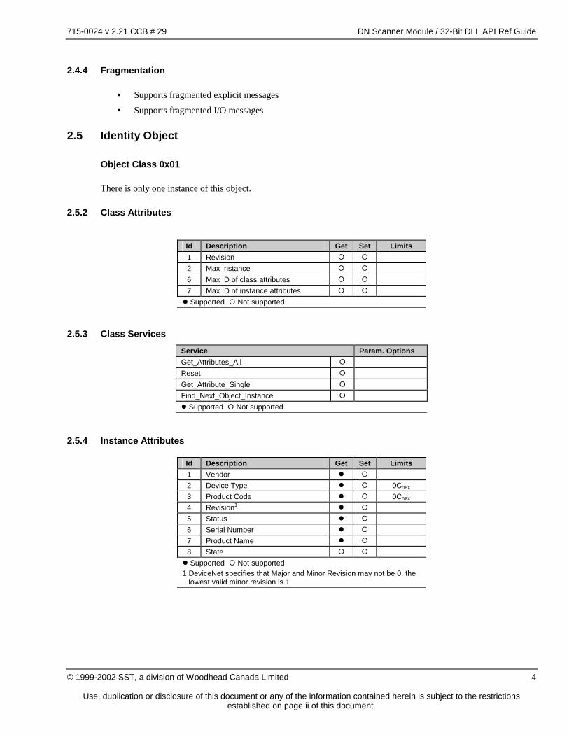
2.4.4 Fragmentation
• Supports fragmented explicit messages
• Supports fragmented I/O messages
2.5 Identity Object
Object Class 0x01
There is only one instance of this object.
2.5.2 Class Attributes
Id Description Get Set Limits 1 Revision � � 2 Max Instance � � 6 Max ID of class attributes � � 7 Max ID of instance attributes � � � Supported � Not supported
2.5.3 Class Services Service Param. Options Get_Attributes_All � Reset � Get_Attribute_Single � Find_Next_Object_Instance � � Supported � Not supported
2.5.4 Instance Attributes
Id Description Get Set Limits 1 Vendor � � 2 Device Type � � 0Chex 3 Product Code � � 0Chex 4 Revision1 � � 5 Status � � 6 Serial Number � � 7 Product Name � � 8 State � � � Supported � Not supported 1 DeviceNet specifies that Major and Minor Revision may not be 0, the
lowest valid minor revision is 1
715-0024 v 2.21 CCB # 29 DN Scanner Module / 32-Bit DLL API Ref Guide
Use, duplication or disclosure of this document or any of the information contained herein is subject to the restrictions established on page ii of this document.
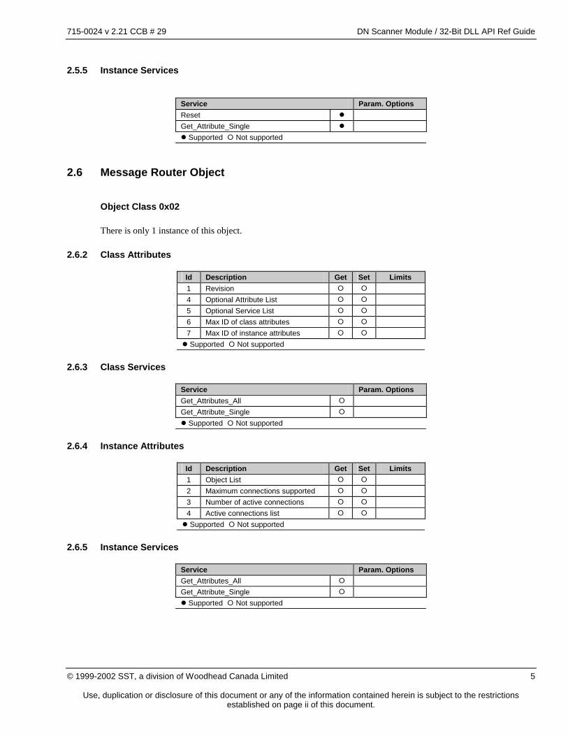
2.5.5 Instance Services
Service Param. Options Reset � Get_Attribute_Single � � Supported � Not supported
2.6 Message Router Object
Object Class 0x02
There is only 1 instance of this object.
2.6.2 Class Attributes
Id Description Get Set Limits 1 Revision � � 4 Optional Attribute List � � 5 Optional Service List � � 6 Max ID of class attributes � � 7 Max ID of instance attributes � � � Supported � Not supported
2.6.3 Class Services
Service Param. Options Get_Attributes_All � Get_Attribute_Single � � Supported � Not supported
2.6.4 Instance Attributes
Id Description Get Set Limits 1 Object List � � 2 Maximum connections supported � � 3 Number of active connections � � 4 Active connections list � � � Supported � Not supported
2.6.5 Instance Services
Service Param. Options Get_Attributes_All � Get_Attribute_Single � � Supported � Not supported
715-0024 v 2.21 CCB # 29 DN Scanner Module / 32-Bit DLL API Ref Guide
Use, duplication or disclosure of this document or any of the information contained herein is subject to the restrictions established on page ii of this document.
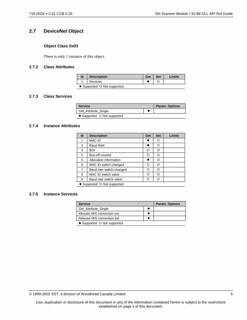
2.7 DeviceNet Object
Object Class 0x03
There is only 1 instance of this object.
2.7.2 Class Attributes
Id Description Get Set Limits 1 Revision � � � Supported � Not supported
2.7.3 Class Services
Service Param. Options Get_Attribute_Single � � Supported � Not supported
2.7.4 Instance Attributes
Id Description Get Set Limits 1 MAC ID � � 2 Baud Rate � � 3 BOI � � 4 Bus-off counter � � 5 Allocation information � � 6 MAC ID switch changed � � 7 Baud rate switch changed � � 8 MAC ID switch value � � 9 Baud rate switch value � � � Supported � Not supported
2.7.5 Instance Services
Service Param. Options Get_Attribute_Single � Allocate M/S connection set � Release M/S connection set � � Supported � Not supported
715-0024 v 2.21 CCB # 29 DN Scanner Module / 32-Bit DLL API Ref Guide
Use, duplication or disclosure of this document or any of the information contained herein is subject to the restrictions established on page ii of this document.
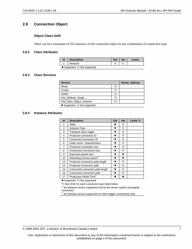
2.8 Connection Object
Object Class 0x05
There can be a maximum of 255 instances of the connection object in any combination of connection type.
2.8.2 Class Attributes
Id Description Get Set Limits 1 Revision � � � Supported � Not supported
2.8.3 Class Services
Service Param. Options Reset � Create � Delete � Get_Attribute_Single � Find_Next_Object_Instance � � Supported � Not supported
2.8.4 Instance Attributes
Id Description Get Set Limits *1 1 State � � 2 Instance Type � � 3 Transport class trigger � � 4 Produced connection ID � � 5 Consumed connection ID � � 6 Initial comm. characteristics � � 7 Produced connection size � � 8 Consumed connection size � � 9 Expected packet rate � � 12 Watchdog timeout action2 � � 13 Produced connection path length � � 14 Produced connection path � � 15 Consumed connection path length � � 16 Consumed connection path � � 17 Production Inhibit Time3 � � � Supported � Not supported *1 See limits for each connection type listed below 2 set attribute service supported only by the server explicit messaging connection 3 set attribute service supported on client trigger connections only
715-0024 v 2.21 CCB # 29 DN Scanner Module / 32-Bit DLL API Ref Guide
Use, duplication or disclosure of this document or any of the information contained herein is subject to the restrictions established on page ii of this document.
Explicit Client Connection Attribute Limits
Id Description Limits/Fixed Value 1 State 2 Instance Type 0 3 Transport class trigger 0x23 4 Produced connection ID 5 Consumed connection ID 6 Initial comm. characteristics 7 Produced connection size 0Xffff 8 Consumed connection size 0xFFFF 9 Expected packet rate 2500 12 Watchdog timeout action 0x01 13 Produced connection path length 0 14 Produced connection path - 15 Consumed connection path length 0 16 Consumed connection path - 17 Production Inhibit Time -
Explicit Server Connection Attribute Limits
Id Description Limits/Fixed Value 1 State 2 Instance Type 0 3 Transport class trigger 0x83 4 Produced connection ID 5 Consumed connection ID 6 Initial comm. characteristics 7 Produced connection size 0xFFFF 8 Consumed connection size 0xFFFF 9 Expected packet rate 2500 12 Watchdog timeout action 0x01 or 0x03 13 Produced connection path length 0 14 Produced connection path - 15 Consumed connection path length 0 16 Consumed connection path - 17 Production Inhibit Time 0xFFFF
715-0024 v 2.21 CCB # 29 DN Scanner Module / 32-Bit DLL API Ref Guide
Use, duplication or disclosure of this document or any of the information contained herein is subject to the restrictions established on page ii of this document.
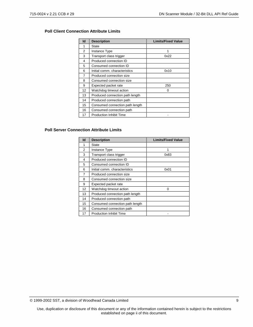
Poll Client Connection Attribute Limits
Id Description Limits/Fixed Value 1 State 2 Instance Type 1 3 Transport class trigger 0x22 4 Produced connection ID 5 Consumed connection ID 6 Initial comm. characteristics 0x10 7 Produced connection size 8 Consumed connection size 9 Expected packet rate 250 12 Watchdog timeout action 0 13 Produced connection path length 14 Produced connection path 15 Consumed connection path length 16 Consumed connection path 17 Production Inhibit Time -
Poll Server Connection Attribute Limits
Id Description Limits/Fixed Value 1 State 2 Instance Type 1 3 Transport class trigger 0x83 4 Produced connection ID 5 Consumed connection ID 6 Initial comm. characteristics 0x01 7 Produced connection size 8 Consumed connection size 9 Expected packet rate 12 Watchdog timeout action 0 13 Produced connection path length 14 Produced connection path 15 Consumed connection path length 16 Consumed connection path 17 Production Inhibit Time -
715-0024 v 2.21 CCB # 29 DN Scanner Module / 32-Bit DLL API Ref Guide
Use, duplication or disclosure of this document or any of the information contained herein is subject to the restrictions established on page ii of this document.
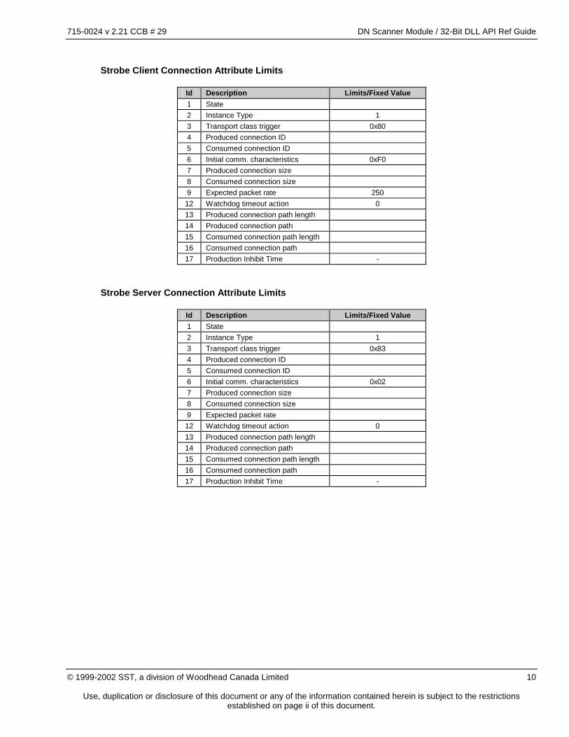
Strobe Client Connection Attribute Limits
Id Description Limits/Fixed Value 1 State 2 Instance Type 1 3 Transport class trigger 0x80 4 Produced connection ID 5 Consumed connection ID 6 Initial comm. characteristics 0xF0 7 Produced connection size 8 Consumed connection size 9 Expected packet rate 250 12 Watchdog timeout action 0 13 Produced connection path length 14 Produced connection path 15 Consumed connection path length 16 Consumed connection path 17 Production Inhibit Time -
Strobe Server Connection Attribute Limits
Id Description Limits/Fixed Value 1 State 2 Instance Type 1 3 Transport class trigger 0x83 4 Produced connection ID 5 Consumed connection ID 6 Initial comm. characteristics 0x02 7 Produced connection size 8 Consumed connection size 9 Expected packet rate 12 Watchdog timeout action 0 13 Produced connection path length 14 Produced connection path 15 Consumed connection path length 16 Consumed connection path 17 Production Inhibit Time -
715-0024 v 2.21 CCB # 29 DN Scanner Module / 32-Bit DLL API Ref Guide
Use, duplication or disclosure of this document or any of the information contained herein is subject to the restrictions established on page ii of this document.
Id Description Limits/Fixed Value 1 State 2 Instance Type 1 3 Transport class trigger 0x03 or 0x13 4 Produced connection ID 5 Consumed connection ID 6 Initial comm. characteristics 0x01 7 Produced connection size 8 Consumed connection size 9 Expected packet rate 250 12 Watchdog timeout action 0 13 Produced connection path length 14 Produced connection path 15 Consumed connection path length 16 Consumed connection path 17 Production Inhibit Time -
COS/Cyclic Server Connection Attribute Limits (acknowledged)
Id Description Limits/Fixed Value 1 State 2 Instance Type 1 3 Transport class trigger 0x03 or 0x13 4 Produced connection ID 5 Consumed connection ID 6 Initial comm. characteristics 0x01 7 Produced connection size 8 Consumed connection size 9 Expected packet rate 250 12 Watchdog timeout action 0 13 Produced connection path length 14 Produced connection path 15 Consumed connection path length 4 16 Consumed connection path 0x20 0x2B 0x24 0x01 17 Production Inhibit Time -
715-0024 v 2.21 CCB # 29 DN Scanner Module / 32-Bit DLL API Ref Guide
Use, duplication or disclosure of this document or any of the information contained herein is subject to the restrictions established on page ii of this document.
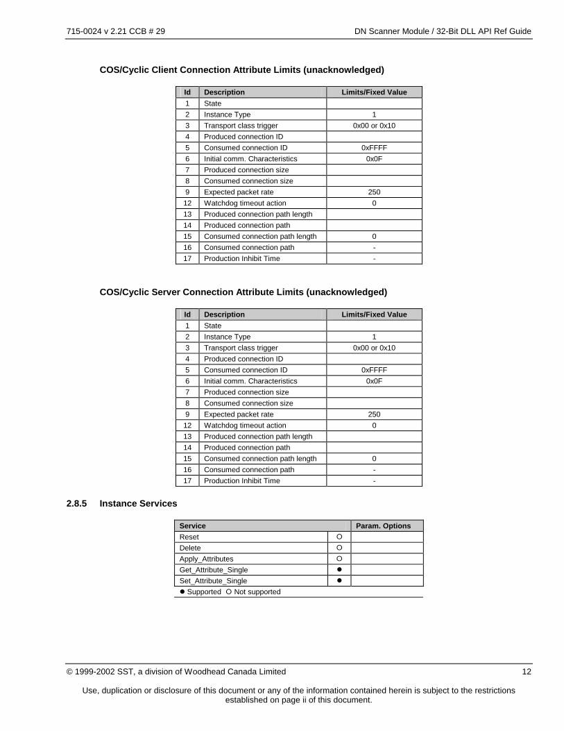
Id Description Limits/Fixed Value 1 State 2 Instance Type 1 3 Transport class trigger 0x00 or 0x10 4 Produced connection ID 5 Consumed connection ID 0xFFFF 6 Initial comm. Characteristics 0x0F 7 Produced connection size 8 Consumed connection size 9 Expected packet rate 250 12 Watchdog timeout action 0 13 Produced connection path length 14 Produced connection path 15 Consumed connection path length 0 16 Consumed connection path - 17 Production Inhibit Time -
COS/Cyclic Server Connection Attribute Limits (unacknowledged)
Id Description Limits/Fixed Value 1 State 2 Instance Type 1 3 Transport class trigger 0x00 or 0x10 4 Produced connection ID 5 Consumed connection ID 0xFFFF 6 Initial comm. Characteristics 0x0F 7 Produced connection size 8 Consumed connection size 9 Expected packet rate 250 12 Watchdog timeout action 0 13 Produced connection path length 14 Produced connection path 15 Consumed connection path length 0 16 Consumed connection path - 17 Production Inhibit Time -
2.8.5 Instance Services
Service Param. Options Reset � Delete � Apply_Attributes � Get_Attribute_Single � Set_Attribute_Single � � Supported � Not supported
715-0024 v 2.21 CCB # 29 DN Scanner Module / 32-Bit DLL API Ref Guide
Use, duplication or disclosure of this document or any of the information contained herein is subject to the restrictions established on page ii of this document.
3 DNSCAN.SS1 Operation
3.1 Introduction
DNSCAN.SS1 (DNSCAN) performs all of the background tasks necessary to maintain messaging connections to DeviceNet devices. The main features of the module are:
• Flexible host interface supports both simple ladder logic and high-level language host applications
• DeviceNet Client
• Support for up to 63 server devices (one MAC ID is used by the scanner)
• Device list may be modified at run-time
• Supports Group 2 Only Slaves
• Supports Group 2 Slaves (UCMM capable)
• Supports UCMM capable servers without the Group 2 Master/Slave Connection Set (explicit messaging only)
• DeviceNet Server
• UCMM Capable Group 2 Server
• Supports Strobe, Poll, Change-of-State, and Cyclic I/O connections
• Objects in the host application are accessible from DeviceNet
3.2 Terminology
Since this module supports both client and server capabilities, we must define certain terms to avoid confusion.
Inputs / Outputs
Throughout this document, inputs and outputs are named according to the process view. Inputs are data that originate in the field and are transmitted to the process controller. Outputs are data that originate in the process controller and are transmitted to the field devices.
Producer / Consumer
DeviceNet is a connection based network, all communications take place across connections. A connection is a communication path between a Producer (that generates the message) and a Consumer (that receives the message. Connections may be one-way (Producer at one end, Consumer at the other), or two way (Producer and Consumer at each end). When a connection sends a message it is said to Produce the message. When a connection receives a message it is said to Consume the message. Refer to the DeviceNet specification for a detailed description of DeviceNet’s connection-based architecture.
715-0024 v 2.21 CCB # 29 DN Scanner Module / 32-Bit DLL API Ref Guide
Use, duplication or disclosure of this document or any of the information contained herein is subject to the restrictions established on page ii of this document.
Client / Server
A client initiates communication on a connection. A server reacts to messages received on a connection. The server’s reaction may cause it to send a response to the client.
Master/Slave Roles
A Master is a client end-point of a Group 2 Master/Slave connection. Masters transmit outputs and receive inputs from Slaves. Masters send explicit requests to Slaves. A Slave is a server end-point of a Group 2 Master/Slave connection. Slaves receive outputs and transmit inputs to a Master. Slaves receive and respond to explicit request messages from a Master. NOTE: It is possible for a single device to be a Master and a Slave at the same time.
3.3 Host Interface
All interaction between the host application and DNSCAN takes place in the Host Interface Block of the shared RAM. There is an interrupt signal from the card to the host application and an interrupt from the host application to the card. These interrupts request action based on changes in the shared RAM.
3.3.1 Application Module Header
The Application Module Header is a section of the Host Interface Block that is common to all application modules for the 5136-DN card. This block contains module identification and runtime status information. See section 4.3.
3.3.2 Command Buffer
The Command Buffer provides a command-response interface to the scanner. Commands are written to the Command Buffer and an interrupt to the card triggers execution of the command. Command results are returned in the Command Buffer. The command buffer interface is used to configure DNSCAN. See section 4.5.
3.3.3 Client Status Block
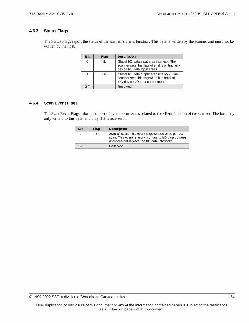
The Client Status Block provides status information related to the client function of the scanner. See section 4.6.
3.3.4 Client Control Block
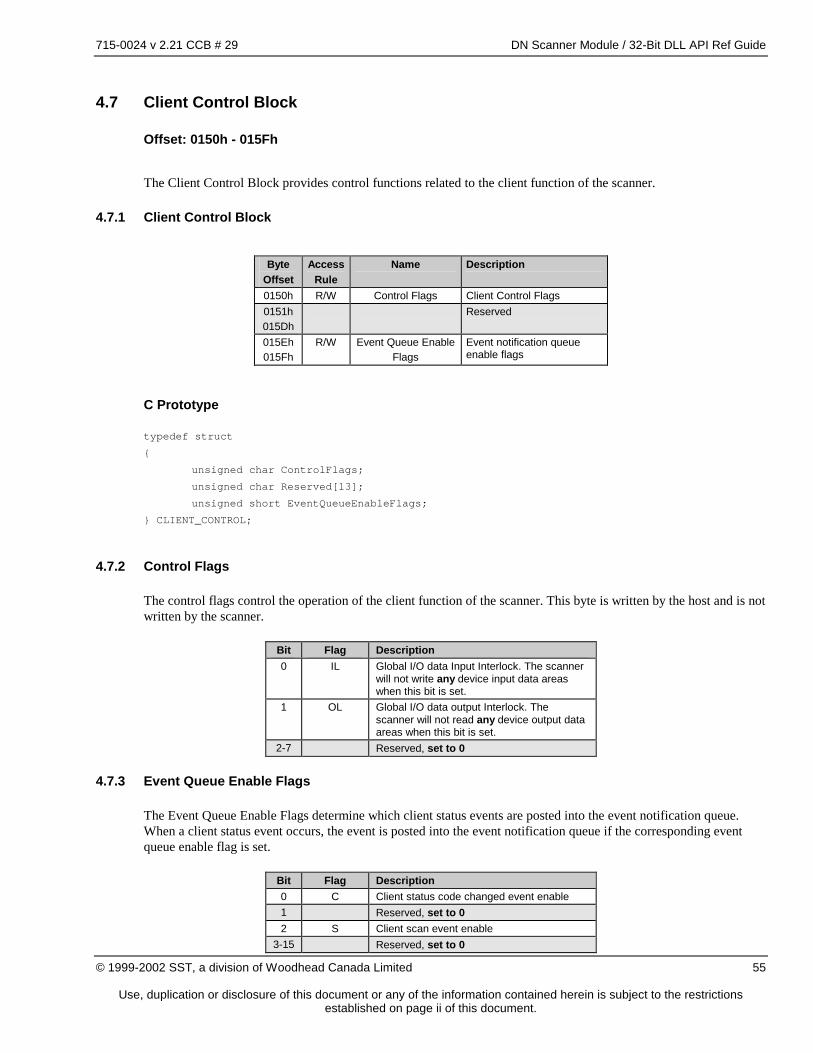
The Client Control Block provides control functions related to the client function of the scanner. See section 4.7.
3.3.5 Server Status Block
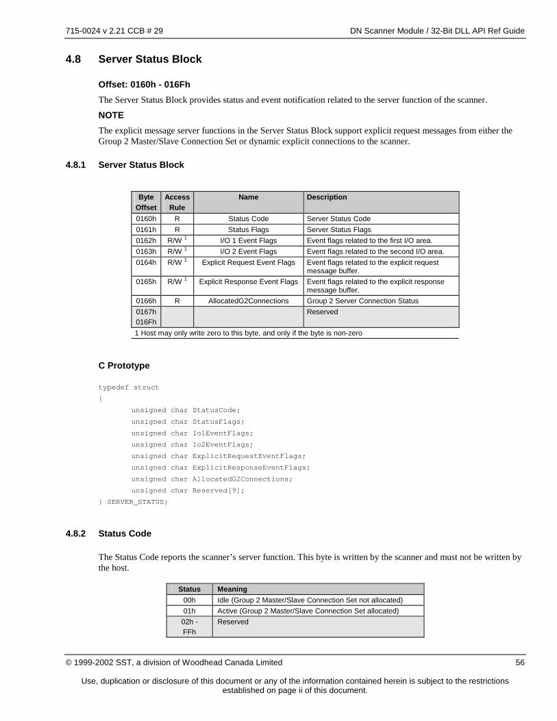
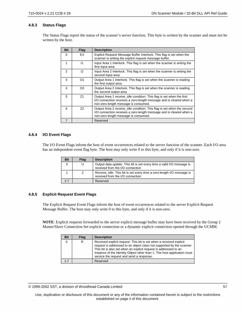
The Server Status Block provides status and event notification related to the server function of the scanner. See section 4.8.
3.3.6 Server Control Block
The Server Control Block provides event triggering and control related to the server function of the scanner. See section 4.9.
715-0024 v 2.21 CCB # 29 DN Scanner Module / 32-Bit DLL API Ref Guide
Use, duplication or disclosure of this document or any of the information contained herein is subject to the restrictions established on page ii of this document.
3.3.7 Device Control Event Table
The Device Control Event Table contains a flag for each MAC ID. The device’s flag must be set by the host if any event flags in the Device Control Table are pending for the device. See section 4.10.
3.3.8 Device Status Table
The Device Status Table contains a status structure for each MAC ID. Each status structure provides event notification and runtime status for the device. See section 4.11.
3.3.9 Device Control Table
The Device Control Table contains a control structure for each MAC ID. Each control structure provides event triggering and control for the device. See section 4.12.
3.3.10 Memory Pool
The Memory Pool is the remainder of the Application Block that is not used by the pre-defined memory areas listed above. This memory may be freely allocated by the application for communication buffers and device I/O data buffers as required.
3.4 Server Configuration
The scanner has the capability to act as a Group 2 Server (Slave) and as an explicit messaging server (via the UCMM). The following sections describe the parameters that configure the operation of the server function of the scanner. Server configuration parameters are set using the DN_ONLINE command in the Command Buffer interface.
715-0024 v 2.21 CCB # 29 DN Scanner Module / 32-Bit DLL API Ref Guide
Use, duplication or disclosure of this document or any of the information contained herein is subject to the restrictions established on page ii of this document.
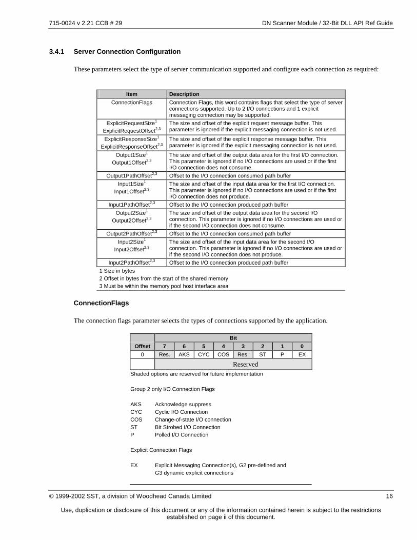
3.4.1 Server Connection Configuration
These parameters select the type of server communication supported and configure each connection as required:
Item Description ConnectionFlags Connection Flags, this word contains flags that select the type of server
connections supported. Up to 2 I/O connections and 1 explicit messaging connection may be supported.
ExplicitRequestSize1 ExplicitRequestOffset2,3
The size and offset of the explicit request message buffer. This parameter is ignored if the explicit messaging connection is not used.
ExplicitResponseSize1 ExplicitResponseOffset2,3
The size and offset of the explicit response message buffer. This parameter is ignored if the explicit messaging connection is not used.
Output1Size1 Output1Offset2,3
The size and offset of the output data area for the first I/O connection. This parameter is ignored if no I/O connections are used or if the first I/O connection does not consume.
Output1PathOffset2,3 Offset to the I/O connection consumed path buffer Input1Size1
Input1Offset2,3 The size and offset of the input data area for the first I/O connection. This parameter is ignored if no I/O connections are used or if the first I/O connection does not produce.
Input1PathOffset2,3 Offset to the I/O connection produced path buffer Output2Size1
Output2Offset2,3 The size and offset of the output data area for the second I/O connection. This parameter is ignored if no I/O connections are used or if the second I/O connection does not consume.
Output2PathOffset2,3 Offset to the I/O connection consumed path buffer Input2Size1
Input2Offset2,3 The size and offset of the input data area for the second I/O connection. This parameter is ignored if no I/O connections are used or if the second I/O connection does not produce.
Input2PathOffset2,3 Offset to the I/O connection produced path buffer 1 Size in bytes 2 Offset in bytes from the start of the shared memory 3 Must be within the memory pool host interface area
ConnectionFlags
The connection flags parameter selects the types of connections supported by the application.
Bit Offset 7 6 5 4 3 2 1 0
0 Res. AKS CYC COS Res. ST P EX
Reserved Shaded options are reserved for future implementation Group 2 only I/O Connection Flags AKS Acknowledge suppress CYC Cyclic I/O Connection COS Change-of-state I/O connection ST Bit Strobed I/O Connection P Polled I/O Connection Explicit Connection Flags EX Explicit Messaging Connection(s), G2 pre-defined and G3 dynamic explicit connections
715-0024 v 2.21 CCB # 29 DN Scanner Module / 32-Bit DLL API Ref Guide
Use, duplication or disclosure of this document or any of the information contained herein is subject to the restrictions established on page ii of this document.
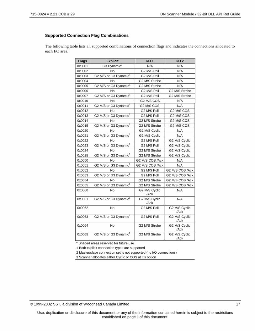
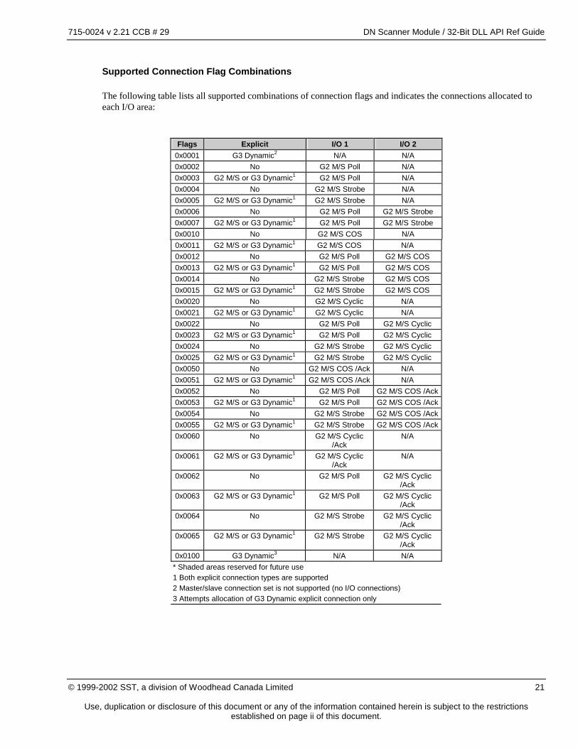
Supported Connection Flag Combinations
The following table lists all supported combinations of connection flags and indicates the connections allocated to each I/O area.
Flags Explicit I/O 1 I/O 2
0x0001 G3 Dynamic2 N/A N/A 0x0002 No G2 M/S Poll N/A 0x0003 G2 M/S or G3 Dynamic1 G2 M/S Poll N/A 0x0004 No G2 M/S Strobe N/A 0x0005 G2 M/S or G3 Dynamic1 G2 M/S Strobe N/A 0x0006 No G2 M/S Poll G2 M/S Strobe 0x0007 G2 M/S or G3 Dynamic1 G2 M/S Poll G2 M/S Strobe 0x0010 No G2 M/S COS N/A 0x0011 G2 M/S or G3 Dynamic1 G2 M/S COS N/A 0x0012 No G2 M/S Poll G2 M/S COS 0x0013 G2 M/S or G3 Dynamic1 G2 M/S Poll G2 M/S COS 0x0014 No G2 M/S Strobe G2 M/S COS 0x0015 G2 M/S or G3 Dynamic1 G2 M/S Strobe G2 M/S COS 0x0020 No G2 M/S Cyclic N/A 0x0021 G2 M/S or G3 Dynamic1 G2 M/S Cyclic N/A 0x0022 No G2 M/S Poll G2 M/S Cyclic 0x0023 G2 M/S or G3 Dynamic1 G2 M/S Poll G2 M/S Cyclic 0x0024 No G2 M/S Strobe G2 M/S Cyclic 0x0025 G2 M/S or G3 Dynamic1 G2 M/S Strobe G2 M/S Cyclic 0x0050 No G2 M/S COS /Ack N/A 0x0051 G2 M/S or G3 Dynamic1 G2 M/S COS /Ack N/A 0x0052 No G2 M/S Poll G2 M/S COS /Ack 0x0053 G2 M/S or G3 Dynamic1 G2 M/S Poll G2 M/S COS /Ack 0x0054 No G2 M/S Strobe G2 M/S COS /Ack 0x0055 G2 M/S or G3 Dynamic1 G2 M/S Strobe G2 M/S COS /Ack 0x0060 No G2 M/S Cyclic
/Ack N/A
0x0061 G2 M/S or G3 Dynamic1 G2 M/S Cyclic /Ack
N/A
0x0062 No G2 M/S Poll G2 M/S Cyclic /Ack
0x0063 G2 M/S or G3 Dynamic1 G2 M/S Poll G2 M/S Cyclic /Ack
0x0064 No G2 M/S Strobe G2 M/S Cyclic /Ack
0x0065 G2 M/S or G3 Dynamic1 G2 M/S Strobe G2 M/S Cyclic /Ack
* Shaded areas reserved for future use 1 Both explicit connection types are supported 2 Master/slave connection set is not supported (no I/O connections) 3 Scanner allocates either Cyclic or COS at it’s option
715-0024 v 2.21 CCB # 29 DN Scanner Module / 32-Bit DLL API Ref Guide
Use, duplication or disclosure of this document or any of the information contained herein is subject to the restrictions established on page ii of this document.
3.5 Client Configuration
The scanner can support multiple client connections to multiple devices. The following sections describe the parameters that configure the operation of each client connection. Client configuration parameters are set using the DN_ADD_DEVICE command in the Command Buffer interface.
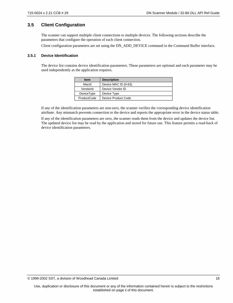
3.5.1 Device Identification
The device list contains device identification parameters. These parameters are optional and each parameter may be used independently as the application requires.
Item Description
MacId Device MAC ID (0-63). VendorId Device Vendor ID
DeviceType Device Type ProductCode Device Product Code
If any of the identification parameters are non-zero, the scanner verifies the corresponding device identification attribute. Any mismatch prevents connection to the device and reports the appropriate error in the device status table. If any of the identification parameters are zero, the scanner reads them from the device and updates the device list. The updated device list may be read by the application and stored for future use. This feature permits a read-back of device identification parameters.
715-0024 v 2.21 CCB # 29 DN Scanner Module / 32-Bit DLL API Ref Guide
Use, duplication or disclosure of this document or any of the information contained herein is subject to the restrictions established on page ii of this document.
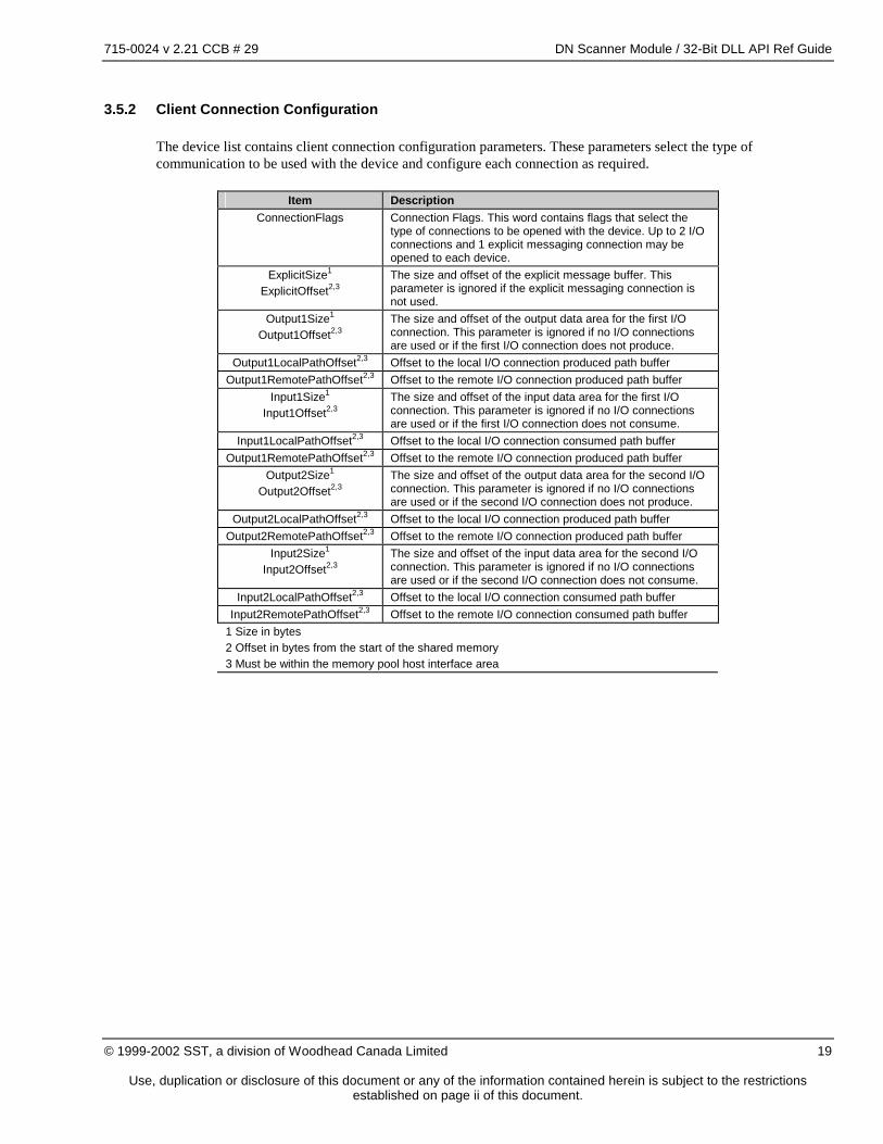
3.5.2 Client Connection Configuration
The device list contains client connection configuration parameters. These parameters select the type of communication to be used with the device and configure each connection as required.
Item Description
ConnectionFlags Connection Flags. This word contains flags that select the type of connections to be opened with the device. Up to 2 I/O connections and 1 explicit messaging connection may be opened to each device.
ExplicitSize1 ExplicitOffset2,3
The size and offset of the explicit message buffer. This parameter is ignored if the explicit messaging connection is not used.
Output1Size1 Output1Offset2,3
The size and offset of the output data area for the first I/O connection. This parameter is ignored if no I/O connections are used or if the first I/O connection does not produce.
Output1LocalPathOffset2,3 Offset to the local I/O connection produced path buffer Output1RemotePathOffset2,3 Offset to the remote I/O connection produced path buffer
Input1Size1 Input1Offset2,3
The size and offset of the input data area for the first I/O connection. This parameter is ignored if no I/O connections are used or if the first I/O connection does not consume.
Input1LocalPathOffset2,3 Offset to the local I/O connection consumed path buffer Output1RemotePathOffset2,3 Offset to the remote I/O connection produced path buffer
Output2Size1 Output2Offset2,3
The size and offset of the output data area for the second I/O connection. This parameter is ignored if no I/O connections are used or if the second I/O connection does not produce.
Output2LocalPathOffset2,3 Offset to the local I/O connection produced path buffer Output2RemotePathOffset2,3 Offset to the remote I/O connection produced path buffer
Input2Size1 Input2Offset2,3
The size and offset of the input data area for the second I/O connection. This parameter is ignored if no I/O connections are used or if the second I/O connection does not consume.
Input2LocalPathOffset2,3 Offset to the local I/O connection consumed path buffer Input2RemotePathOffset2,3 Offset to the remote I/O connection consumed path buffer
1 Size in bytes 2 Offset in bytes from the start of the shared memory 3 Must be within the memory pool host interface area
715-0024 v 2.21 CCB # 29 DN Scanner Module / 32-Bit DLL API Ref Guide
Use, duplication or disclosure of this document or any of the information contained herein is subject to the restrictions established on page ii of this document.
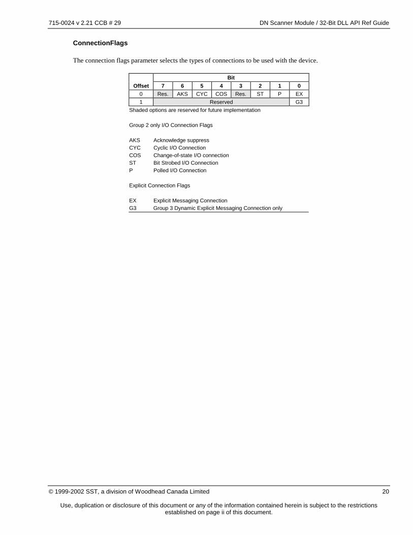
ConnectionFlags
The connection flags parameter selects the types of connections to be used with the device.
Bit Offset 7 6 5 4 3 2 1 0
0 Res. AKS CYC COS Res. ST P EX 1 Reserved G3
Shaded options are reserved for future implementation Group 2 only I/O Connection Flags AKS Acknowledge suppress CYC Cyclic I/O Connection COS Change-of-state I/O connection ST Bit Strobed I/O Connection P Polled I/O Connection Explicit Connection Flags EX Explicit Messaging Connection G3 Group 3 Dynamic Explicit Messaging Connection only
715-0024 v 2.21 CCB # 29 DN Scanner Module / 32-Bit DLL API Ref Guide
Use, duplication or disclosure of this document or any of the information contained herein is subject to the restrictions established on page ii of this document.
Supported Connection Flag Combinations
The following table lists all supported combinations of connection flags and indicates the connections allocated to each I/O area:
Flags Explicit I/O 1 I/O 2
0x0001 G3 Dynamic2 N/A N/A 0x0002 No G2 M/S Poll N/A 0x0003 G2 M/S or G3 Dynamic1 G2 M/S Poll N/A 0x0004 No G2 M/S Strobe N/A 0x0005 G2 M/S or G3 Dynamic1 G2 M/S Strobe N/A 0x0006 No G2 M/S Poll G2 M/S Strobe 0x0007 G2 M/S or G3 Dynamic1 G2 M/S Poll G2 M/S Strobe 0x0010 No G2 M/S COS N/A 0x0011 G2 M/S or G3 Dynamic1 G2 M/S COS N/A 0x0012 No G2 M/S Poll G2 M/S COS 0x0013 G2 M/S or G3 Dynamic1 G2 M/S Poll G2 M/S COS 0x0014 No G2 M/S Strobe G2 M/S COS 0x0015 G2 M/S or G3 Dynamic1 G2 M/S Strobe G2 M/S COS 0x0020 No G2 M/S Cyclic N/A 0x0021 G2 M/S or G3 Dynamic1 G2 M/S Cyclic N/A 0x0022 No G2 M/S Poll G2 M/S Cyclic 0x0023 G2 M/S or G3 Dynamic1 G2 M/S Poll G2 M/S Cyclic 0x0024 No G2 M/S Strobe G2 M/S Cyclic 0x0025 G2 M/S or G3 Dynamic1 G2 M/S Strobe G2 M/S Cyclic 0x0050 No G2 M/S COS /Ack N/A 0x0051 G2 M/S or G3 Dynamic1 G2 M/S COS /Ack N/A 0x0052 No G2 M/S Poll G2 M/S COS /Ack 0x0053 G2 M/S or G3 Dynamic1 G2 M/S Poll G2 M/S COS /Ack 0x0054 No G2 M/S Strobe G2 M/S COS /Ack 0x0055 G2 M/S or G3 Dynamic1 G2 M/S Strobe G2 M/S COS /Ack 0x0060 No G2 M/S Cyclic
/Ack N/A
0x0061 G2 M/S or G3 Dynamic1 G2 M/S Cyclic /Ack
N/A
0x0062 No G2 M/S Poll G2 M/S Cyclic /Ack
0x0063 G2 M/S or G3 Dynamic1 G2 M/S Poll G2 M/S Cyclic /Ack
0x0064 No G2 M/S Strobe G2 M/S Cyclic /Ack
0x0065 G2 M/S or G3 Dynamic1 G2 M/S Strobe G2 M/S Cyclic /Ack
0x0100 G3 Dynamic3 N/A N/A * Shaded areas reserved for future use 1 Both explicit connection types are supported 2 Master/slave connection set is not supported (no I/O connections) 3 Attempts allocation of G3 Dynamic explicit connection only
715-0024 v 2.21 CCB # 29 DN Scanner Module / 32-Bit DLL API Ref Guide
Use, duplication or disclosure of this document or any of the information contained herein is subject to the restrictions established on page ii of this document.
3.6 Master Configuration
The scanner has the capability of acting as a Group 2 Master/Slave Connection Set client (Master). The following sections describe the parameters that configure the operation of the Master function of the scanner. Master configuration parameters are set using the DN_ONLINE command in the Command Buffer interface.
Item Description
ScanInterval Group 2 Master/Slave Connection Set scan interval in ms. If this value is zero, the scan is as fast as the network parameters and traffic permit.
ReconnectTime Specifies the interval (in milliseconds) the scanner waits between reconnection attempts for devices that are faulted (timeout, connection attempt errors).
3.7 Scanner Configuration
The scanner has several distinct capabilities, but all rely on a connection to a DeviceNet network. The following sections describe the general scanner configuration parameters that affect all functions. Scanner configuration parameters are set using the DN_ONLINE command in the Command Buffer interface.
Item Description
MAC ID DeviceNet MAC ID for the scanner Baud Rate DeviceNet Baud Rate
3.7.1 COMM Led
Indicates the communication status of the Scanner application.
COMM Led Status Off Offline
Flashing Green Online - no connections active Solid Green Online - at least 1 connection is active Solid Red Bus Off
715-0024 v 2.21 CCB # 29 DN Scanner Module / 32-Bit DLL API Ref Guide
Use, duplication or disclosure of this document or any of the information contained herein is subject to the restrictions established on page ii of this document.
3.8 Master Operation
This section applies to Group 2 Master/Slave I/O connections.
3.8.1 Group 2 Master/Slave I/O Scan Timing
Group 2 Master/Slave Connection Set scan timing is dynamically controlled by DNSCAN and is affected by several factors (in decreasing order of significance):
• Scan Interval parameter (minimum interval)
• The number of devices being scanned
• Network Baud Rate
• Other I/O traffic on the network (peer-to-peer, other scanners)
• Device timeout
• Group 2 Only Slave overhead (proxy management)
• Explicit messaging traffic
Scan Interval Parameter
This parameter is part of the DN_ONLINE command to the command buffer interface. This value specifies the minimum scan interval. If the minimum scan interval (due to network loading factors listed below) is greater than the Scan Interval parameter, the Scan Interval parameter has no effect. The scan interval parameter can limit the rate of the I/O scan. It cannot speed up the I/O scan faster than network factors allow.
Network Baud Rate
The network baud rate has a large impact on the scan rate, especially if another Master is on the same bus. At slower baud rates, the network time necessary to exchange all I/O messages can exceed the processing time the scanner requires to process the messages.
Number of Devices
As more devices are added to the device list, the overhead of scanning the network increases.
Other I/O Traffic
I/O traffic uses the highest priority network messages. If there is peer-to-peer I/O traffic or another scanner on the same network, I/O messages may be delayed if higher priority messages are being sent. The effect of other I/O traffic is more significant at lower baud rates.
Device Timeout
When a device response is not received the current scan cycle is extended allowing extra time for the expected reply. If the device fails to respond for three consecutive scan cycles, the device is flagged as not present and the reconnection sequence is initiated.
715-0024 v 2.21 CCB # 29 DN Scanner Module / 32-Bit DLL API Ref Guide
Use, duplication or disclosure of this document or any of the information contained herein is subject to the restrictions established on page ii of this document.
Group 2 Only Slave Overhead
Group 2 Only Slaves are simple devices such as photo-detectors and limit switches that have limited processing power. The scanner must provide explicit messaging proxy services on behalf of these devices. Each explicit message (i.e. from a configuration tool) sent to a Group 2 Slave that is being scanned must pass through the scanner. This introduces a small “hiccup” into the scan cycle. This effect is typically undetectable unless a large number of explicit messages are being transmitted, or a bulk upload or download of configuration data is being performed.
Explicit Message Traffic
Explicit message traffic to the scanner, or from the scanner to server devices, requires CPU time to process. Each explicit message introduces a small “hiccup” into the scan cycle. This effect is typically undetectable unless a large number of explicit messages are being transmitted, or a bulk upload or download of configuration data is being performed.
715-0024 v 2.21 CCB # 29 DN Scanner Module / 32-Bit DLL API Ref Guide
Use, duplication or disclosure of this document or any of the information contained herein is subject to the restrictions established on page ii of this document.
3.9 Client Operation
This section applies to all client connections including Group 2 Master/Slave client connections.
3.9.1 Initialization
Client connections are created when the scanner is activated with the DN_START_SCAN command.
3.9.2 Device Initialization
When the scanner is started, device initialization is performed sequentially for each device in the device list.
• Open explicit messaging connection
• Read and verify device identification
• Create I/O connections
• Read and verify I/O connection sizes
3.9.3 Device Timeout / Live Insertion of Devices
When a device stops responding, the scanner attempts to reconnect at regular intervals. This reconnection process is the same as the device initialization process. The automatic reconnection permits devices to be removed and reconnected while the scanner is running without disrupting communications with other devices on the network.
3.9.4 I/O Active & I/O Idle
DeviceNet has support for “idle” I/O messages (messages with zero data bytes). Receipt of a zero-length messages indicates a “receive_idle” condition which may trigger a special response in a device. The actual behavior of devices under these conditions is vendor-specific. An application may optionally send a heartbeat (see section 4.5.10, IO_ACTIVE Command) to the scanner that must be repeated at regular intervals or the I/O messages are forced to zero-length. This mechanism forces the I/O messages to zero length if the host application is terminated. Client I/O connections report the receipt of zero length I/O messages (receive_idle condition) via flags in the Device Status Table.
3.9.5 I/O Data Interlocks
I/O data access interlocks are used to prevent access collisions between the scanner and host application. An access collision can result in reading partially updated data. This condition can have quite serious side effects for data types larger than 1 byte. I/O data interlocks can be handled in 2 ways:
1. Lock and access each device I/O data independently (Device Status/Control Table I/O Interlock flags). 2. Lock all device I/O data simultaneously (Client Status/Control Table I/O Interlock Flags)
The scanner always uses both methods, first requesting the Global I/O Data Interlock and then requesting each individual Device I/O Data Interlock. This allows the application to use either approach and still guarantees I/O data integrity.
715-0024 v 2.21 CCB # 29 DN Scanner Module / 32-Bit DLL API Ref Guide
Use, duplication or disclosure of this document or any of the information contained herein is subject to the restrictions established on page ii of this document.
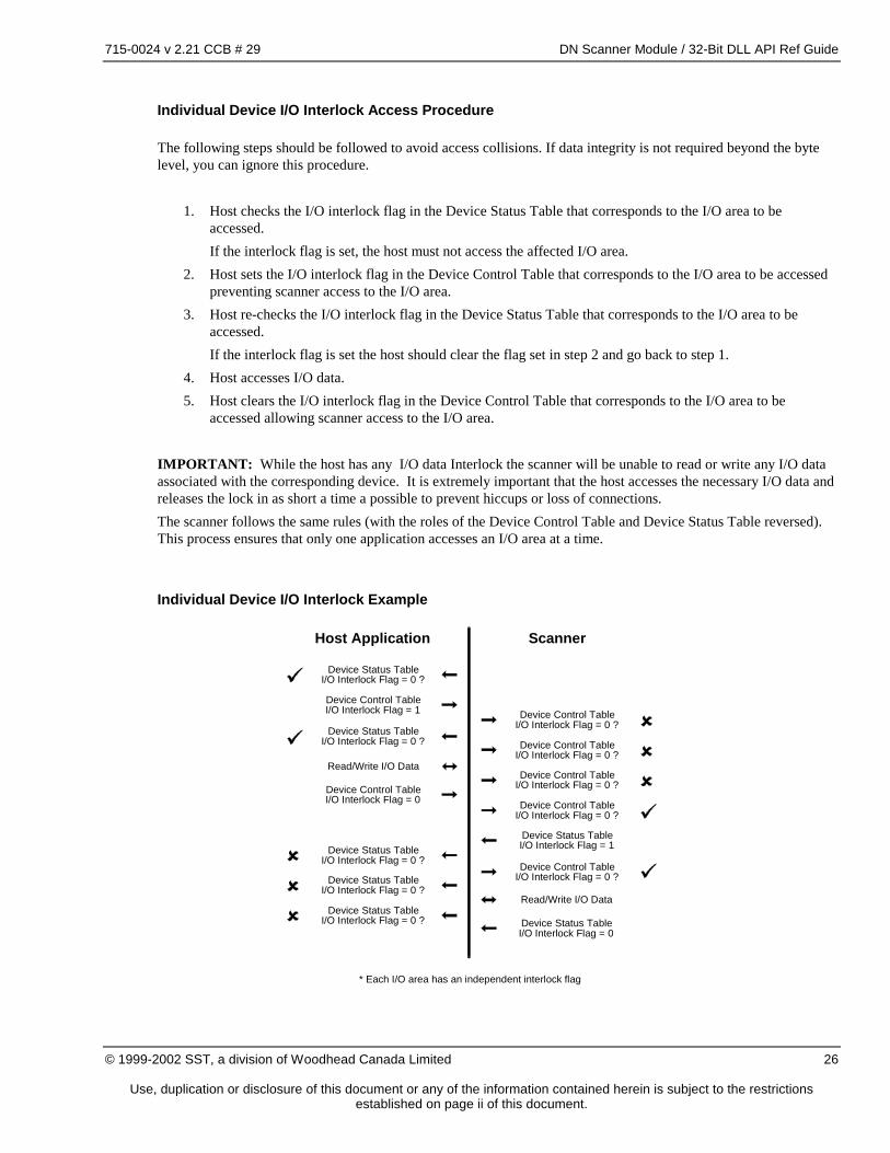
Individual Device I/O Interlock Access Procedure
The following steps should be followed to avoid access collisions. If data integrity is not required beyond the byte level, you can ignore this procedure.
1. Host checks the I/O interlock flag in the Device Status Table that corresponds to the I/O area to be accessed.
If the interlock flag is set, the host must not access the affected I/O area. 2. Host sets the I/O interlock flag in the Device Control Table that corresponds to the I/O area to be accessed
preventing scanner access to the I/O area. 3. Host re-checks the I/O interlock flag in the Device Status Table that corresponds to the I/O area to be
accessed. If the interlock flag is set the host should clear the flag set in step 2 and go back to step 1. 4. Host accesses I/O data. 5. Host clears the I/O interlock flag in the Device Control Table that corresponds to the I/O area to be
accessed allowing scanner access to the I/O area. IMPORTANT: While the host has any I/O data Interlock the scanner will be unable to read or write any I/O data associated with the corresponding device. It is extremely important that the host accesses the necessary I/O data and releases the lock in as short a time a possible to prevent hiccups or loss of connections. The scanner follows the same rules (with the roles of the Device Control Table and Device Status Table reversed). This process ensures that only one application accesses an I/O area at a time.
Individual Device I/O Interlock Example
Host Application Scanner
Device Status TableI/O Interlock Flag = 0 ?
Device Control TableI/O Interlock Flag = 0 ?
Device Status TableI/O Interlock Flag = 0 ?
Device Status TableI/O Interlock Flag = 0 ?
Device Status TableI/O Interlock Flag = 0 ?
Device Status TableI/O Interlock Flag = 0 ?
Device Control TableI/O Interlock Flag = 0 ?
Device Control TableI/O Interlock Flag = 0 ?
Device Control TableI/O Interlock Flag = 0 ?
Device Control TableI/O Interlock Flag = 0 ?
Read/Write I/O Data
Read/Write I/O Data
Device Control TableI/O Interlock Flag = 1
Device Control TableI/O Interlock Flag = 0
Device Status TableI/O Interlock Flag = 0
* Each I/O area has an independent interlock flag
Device Status TableI/O Interlock Flag = 1
715-0024 v 2.21 CCB # 29 DN Scanner Module / 32-Bit DLL API Ref Guide
Use, duplication or disclosure of this document or any of the information contained herein is subject to the restrictions established on page ii of this document.
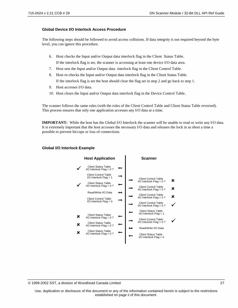
Global Device I/O Interlock Access Procedure
The following steps should be followed to avoid access collisions. If data integrity is not required beyond the byte level, you can ignore this procedure.
6. Host checks the Input and/or Output data interlock flag in the Client Status Table. If the interlock flag is set, the scanner is accessing at least one device I/O data area. 7. Host sets the Input and/or Output data interlock flag in the Client Control Table. 8. Host re-checks the Input and/or Output data interlock flag in the Client Status Table. If the interlock flag is set the host should clear the flag set in step 2 and go back to step 1. 9. Host accesses I/O data. 10. Host clears the Input and/or Output data interlock flag in the Device Control Table.
The scanner follows the same rules (with the roles of the Client Control Table and Client Status Table reversed). This process ensures that only one application accesses any I/O data at a time. IMPORTANT: While the host has the Global I/O Interlock the scanner will be unable to read or write any I/O data. It is extremely important that the host accesses the necessary I/O data and releases the lock in as short a time a possible to prevent hiccups or loss of connections.
Global I/O Interlock Example
Host Application Scanner
Client Status TableI/O Interlock Flag = 0 ?
Client Control TableI/O Interlock Flag = 0 ?
Client Status TableI/O Interlock Flag = 0 ?
Client Status TableI/O Interlock Flag = 0 ?
Client Status TableI/O Interlock Flag = 0 ?
Client Status TableI/O Interlock Flag = 0 ?
Client Control TableI/O Interlock Flag = 0 ?
Client Control TableI/O Interlock Flag = 0 ?
Client Control TableI/O Interlock Flag = 0 ?
Client Control TableI/O Interlock Flag = 0 ?
Read/Write I/O Data
Read/Write I/O Data
Client Control TableI/O Interlock Flag = 1
Client Control TableI/O Interlock Flag = 0
Client Status TableI/O Interlock Flag = 0
Client Status TableI/O Interlock Flag = 1
715-0024 v 2.21 CCB # 29 DN Scanner Module / 32-Bit DLL API Ref Guide
Use, duplication or disclosure of this document or any of the information contained herein is subject to the restrictions established on page ii of this document.
I/O Interlock Faults
While any I/O interlock flag is set, the scanner is unable to continue I/O communications with the affected device(s). If this condition persists, the device connection may time out or hiccups in the scan may occur. The host application must ensure that the I/O interlock flags are set only when necessary and are cleared as soon as possible.
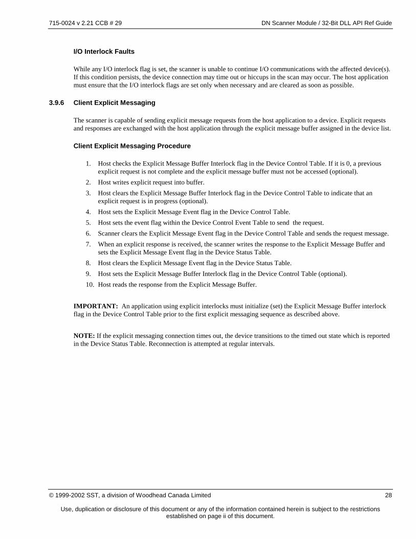
3.9.6 Client Explicit Messaging
The scanner is capable of sending explicit message requests from the host application to a device. Explicit requests and responses are exchanged with the host application through the explicit message buffer assigned in the device list.
Client Explicit Messaging Procedure
1. Host checks the Explicit Message Buffer Interlock flag in the Device Control Table. If it is 0, a previous explicit request is not complete and the explicit message buffer must not be accessed (optional).
2. Host writes explicit request into buffer. 3. Host clears the Explicit Message Buffer Interlock flag in the Device Control Table to indicate that an
explicit request is in progress (optional). 4. Host sets the Explicit Message Event flag in the Device Control Table. 5. Host sets the event flag within the Device Control Event Table to send the request. 6. Scanner clears the Explicit Message Event flag in the Device Control Table and sends the request message. 7. When an explicit response is received, the scanner writes the response to the Explicit Message Buffer and
sets the Explicit Message Event flag in the Device Status Table. 8. Host clears the Explicit Message Event flag in the Device Status Table. 9. Host sets the Explicit Message Buffer Interlock flag in the Device Control Table (optional). 10. Host reads the response from the Explicit Message Buffer.
IMPORTANT: An application using explicit interlocks must initialize (set) the Explicit Message Buffer interlock flag in the Device Control Table prior to the first explicit messaging sequence as described above. NOTE: If the explicit messaging connection times out, the device transitions to the timed out state which is reported in the Device Status Table. Reconnection is attempted at regular intervals.
715-0024 v 2.21 CCB # 29 DN Scanner Module / 32-Bit DLL API Ref Guide
Use, duplication or disclosure of this document or any of the information contained herein is subject to the restrictions established on page ii of this document.
Client Explicit Messaging Example
Host Application Scanner
Write ExplicitRequest
Read ExplicitResponse
Read andSend Explicit Request
* Device Control TableExplicit Interlock Flag = 1 ?
Device Status TableExplicit Event Flag = 1 ?
Device Status TableExplicit Event Flag = 1 ?
Device Status TableExplicit Event Flag = 1 ?
Device Control Event TableControl Event Flag = 1 ?
* Device Control TableExplicit Interlock Flag = 0
Device Control TableExplicit Event Flag = 1 ?
Device Status TableExplicit Event Flag = 1
* Not required if host implements a different explicitmessaging synchronization/interlock technique.
(interlock flags are not used by the scanner module)
Write Explicit Response
Device Control TableExplicit Event Flag = 1
Device Status TableExplicit Event Flag = 0
* Device Control TableExplicit InterlockFlag = 1
Device Control TableExplicit Event Flag = 0
Device Control EventTableControl Event Flag = 1 ?
Device Control Event TableControl Event Flag = 0
Client Explicit Request Format
The host uses this message format to send explicit requests to devices in the device list. This message is written into the device’s explicit message buffer.
Offset Name Data Type Description
0 Size word Number of Service Data bytes 2 Service word DeviceNet service code 4 Class 1 word The object class to which this is requested. 6 Instance 1 word The specific instance of the object class to
which this request is directed. 8 Service Data - Optional data as required by the service.
1 If the explicit message connection body format cannot represent the request an internally generated explicit error response is returned.
715-0024 v 2.21 CCB # 29 DN Scanner Module / 32-Bit DLL API Ref Guide
Use, duplication or disclosure of this document or any of the information contained herein is subject to the restrictions established on page ii of this document.
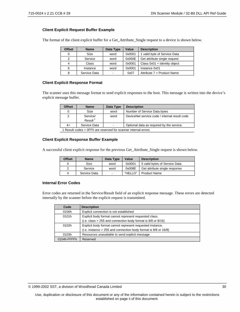
Client Explicit Request Buffer Example
The format of the client explicit buffer for a Get_Attribute_Single request to a device is shown below.
Offset Name Data Type Value Description 0 Size word 0x0001 1 valid byte of Service Data 2 Service word 0x000E Get attribute single request 4 Class word 0x0001 Class 0x01 = Identity object 6 Instance word 0x0001 Instance 0x01 8 Service Data - 0x07 Attribute 7 = Product Name
Client Explicit Response Format
The scanner uses this message format to send explicit responses to the host. This message is written into the device’s explicit message buffer.
Offset Name Data Type Description
0 Size word Number of Service Data bytes 2 Service/
Result 1 word DeviceNet service code / internal result code
4+ Service Data - Optional data as required by the service. 1 Result codes > 0FFh are reserved for scanner internal errors
Client Explicit Response Buffer Example
A successful client explicit response for the previous Get_Attribute_Single request is shown below.
Offset Name Data Type Value Description 0 Size word 0x0001 5 valid bytes of Service Data 2 Service word 0x008E Get attribute single response 4 Service Data - “HELLO” Product Name
Internal Error Codes
Error codes are returned in the Service/Result field of an explicit response message. These errors are detected internally by the scanner before the explicit request is transmitted.
Code Description 0100h Explicit connection is not established 0101h Explicit body format cannot represent requested class.
(i.e. class > 255 and connection body format is 8/8 or 8/16) 0102h Explicit body format cannot represent requested instance.
(i.e. instance > 255 and connection body format is 8/8 or 16/8) 0103h Resources unavailable to send explicit message
0104h-FFFFh Reserved
715-0024 v 2.21 CCB # 29 DN Scanner Module / 32-Bit DLL API Ref Guide
Use, duplication or disclosure of this document or any of the information contained herein is subject to the restrictions established on page ii of this document.
3.10 Server Operation
This section applies to all server connections including Group 2 Master/Slave Server connections.
3.10.1 Initialization
Server connections are established by a client device via allocation of the Group 2 Master/Slave Connection Set or though the UCMM. The allocation status of the Group 2 Master/Slave Connection Set is reported in the Server Status Block.
3.10.2 I/O Active & I/O Idle
DeviceNet has support for “idle” I/O messages (messages with zero data bytes). Receipt of a zero-length message indicates a “receive_idle” condition which may trigger a special response in a device. The actual behavior of devices under these conditions is vendor-specific. An application may optionally send a heartbeat (see section 4.5.10, IO_ACTIVE Command) to the scanner at regular intervals. If the heartbeat is lost the I/O messages are forced to zero-length. This mechanism forces the I/O messages to zero length if the host application is terminated. Server I/O connections report the receipt of zero length I/O messages (receive_idle condition) via flags in the Server Status Block.
3.10.3 I/O Data Interlocks
I/O data access interlocks are used to prevent access collisions between the scanner and host application. An access collision can result in reading partially updated data. This condition can have quite serious side effects for data types larger than 1 byte.
Server I/O Access Procedure
The following steps should be followed to avoid access collisions. If data integrity is not required beyond the byte level you can ignore this procedure.
1. Host checks the I/O interlock flag in the Server Status Block that corresponds to the I/O area to be accessed. If the interlock flag is set the host should not access the affected I/O area.
2. Host sets the I/O interlock flag in the Server Control Block that corresponds to the I/O area to be accessed preventing scanner access to the I/O area.
3. Host re-checks the I/O interlock flag in the Server Status Block that corresponds to the target I/O area. If the interlock flag is set the host should clear the flag set in step 2 and go back to step 1. 4. Host accesses I/O data 5. Host clears the I/O interlock flag in the Server Control Block that corresponds to the target I/O area
allowing scanner access to the I/O area. The scanner follows the same rules with the roles of the Server Control Block and Server Status Block reversed. This process ensures that only one application accesses a given I/O area at a time.
715-0024 v 2.21 CCB # 29 DN Scanner Module / 32-Bit DLL API Ref Guide
Use, duplication or disclosure of this document or any of the information contained herein is subject to the restrictions established on page ii of this document.
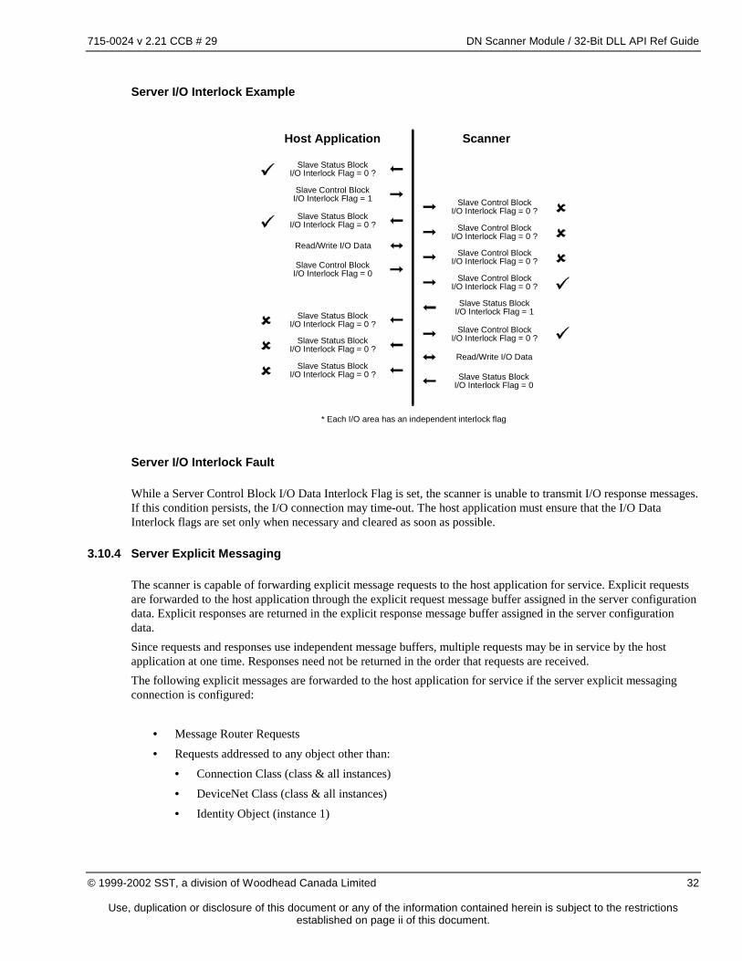
Server I/O Interlock Example
* Each I/O area has an independent interlock flag
Host Application Scanner
Slave Status BlockI/O Interlock Flag = 0 ?
Slave Control BlockI/O Interlock Flag = 0 ?
Slave Status BlockI/O Interlock Flag = 0 ?
Slave Status BlockI/O Interlock Flag = 0 ?
Slave Status BlockI/O Interlock Flag = 0 ?
Slave Status BlockI/O Interlock Flag = 0 ?
Slave Control BlockI/O Interlock Flag = 0 ?
Slave Control BlockI/O Interlock Flag = 0 ?
Slave Control BlockI/O Interlock Flag = 0 ?
Slave Control BlockI/O Interlock Flag = 0 ?
Read/Write I/O Data
Read/Write I/O Data
Slave Control BlockI/O Interlock Flag = 1
Slave Control BlockI/O Interlock Flag = 0
Slave Status BlockI/O Interlock Flag = 0
Slave Status BlockI/O Interlock Flag = 1
Server I/O Interlock Fault
While a Server Control Block I/O Data Interlock Flag is set, the scanner is unable to transmit I/O response messages. If this condition persists, the I/O connection may time-out. The host application must ensure that the I/O Data Interlock flags are set only when necessary and cleared as soon as possible.
3.10.4 Server Explicit Messaging
The scanner is capable of forwarding explicit message requests to the host application for service. Explicit requests are forwarded to the host application through the explicit request message buffer assigned in the server configuration data. Explicit responses are returned in the explicit response message buffer assigned in the server configuration data. Since requests and responses use independent message buffers, multiple requests may be in service by the host application at one time. Responses need not be returned in the order that requests are received. The following explicit messages are forwarded to the host application for service if the server explicit messaging connection is configured:
• Message Router Requests
• Requests addressed to any object other than:
• Connection Class (class & all instances)
• DeviceNet Class (class & all instances)
• Identity Object (instance 1)
715-0024 v 2.21 CCB # 29 DN Scanner Module / 32-Bit DLL API Ref Guide
Use, duplication or disclosure of this document or any of the information contained herein is subject to the restrictions established on page ii of this document.
If server explicit messaging is supported, the host must handle all Message Router Object requests. If server explicit messaging is not supported, the default Message Router Object in the scanner, which does not support any services, will return an error to all explicit requests.
Explicit requests received by the Group 2 Master/Slave Connection Set explicit connection and dynamic explicit connections opened through the UCMM are forwarded to the server explicit message buffer. The host application is responsible for servicing all explicit requests and returning a valid response or error response in a timely manner. If the explicit server messaging connection is not enabled, all unsupported explicit requests return an appropriate DeviceNet error response.
Server Explicit Request Procedure
1. Scanner receives an explicit request that is not serviced by internal objects. 2. Scanner checks Explicit Request Interlock Flag in the Server Status Block. If the Explicit Request Interlock Flag is 0, a previous explicit request has not been read by the host. The
current explicit request is deferred until the pending request has been read. 3. Scanner writes the explicit request to the Explicit Request Message Buffer. If the Explicit Request Message
Buffer is too small for the message, the scanner returns a “too_much_data” error response. 4. Scanner clears the Explicit Request Interlock Flag in the Server Status Block and sets the Explicit Request
Event Flag in the Server Status Block. 5. Host clears the Explicit Request Event Flag in the Server Status Block and reads the message from the
Explicit Request Message Buffer. 6. Host sets the Explicit Request Event Flag in the Server Control Block. 7. Scanner clears the Explicit Request Event Flag in the Server Control Block. 8. Scanner sets the Explicit Request Interlock Flag in the Server Status Block.
715-0024 v 2.21 CCB # 29 DN Scanner Module / 32-Bit DLL API Ref Guide
Use, duplication or disclosure of this document or any of the information contained herein is subject to the restrictions established on page ii of this document.
Server Explicit Request Example
Read ExplicitRequest
Server Control BlockExplicit RequestEvent Flag = 1 ?
Server Control BlockExplicit RequestEvent Flag = 1 ?
Server Status BlockExplicit RequestEvent Flag = 1 ?
Server Status BlockExplicit RequestEvent Flag = 1 ?
Server Status BlockExplicit Request
Interlock Flag = 1?
Write Explicit Request
Server Status BlockExplicit RequestInterlock Flag = 0
Server Status BlockExplicit RequestInterlock Flag = 1
Server Status BlockExplicit RequestEvent Flag = 1
Receive Explicit Request
Host Application Scanner
Server Status BlockExplicit RequestEvent Flag = 0
Server Control BlockExplicit RequestEvent Flag = 1
Server Explicit Response Procedure
1. Host completes service of a previously received explicit request. 2. Host checks Explicit Response Interlock Flag in the Server Control Block (optional). If the Explicit Response Interlock Flag is 0, a previous explicit response has not been read by the scanner.
The current explicit response must be deferred until the pending response has been read. 3. Host writes the explicit response to the Explicit Response Message Buffer. 4. Host clears the Explicit Response Interlock Flag in the Server Control Block (optional). 5. Host sets the Explicit Response Event Flag in the Server Control Block. 6. Scanner clears the Explicit Response Event Flag in the Server Control Block and reads the message from
the Explicit Response Message Buffer. 7. Scanner sets the Explicit Response Event Flag in the Server Status Block. 8. Host clears the Explicit Response Event Flag in the Server Status Block. 9. Host sets the Explicit Response Interlock Flag in the Server Control Block (optional).
715-0024 v 2.21 CCB # 29 DN Scanner Module / 32-Bit DLL API Ref Guide
Use, duplication or disclosure of this document or any of the information contained herein is subject to the restrictions established on page ii of this document.
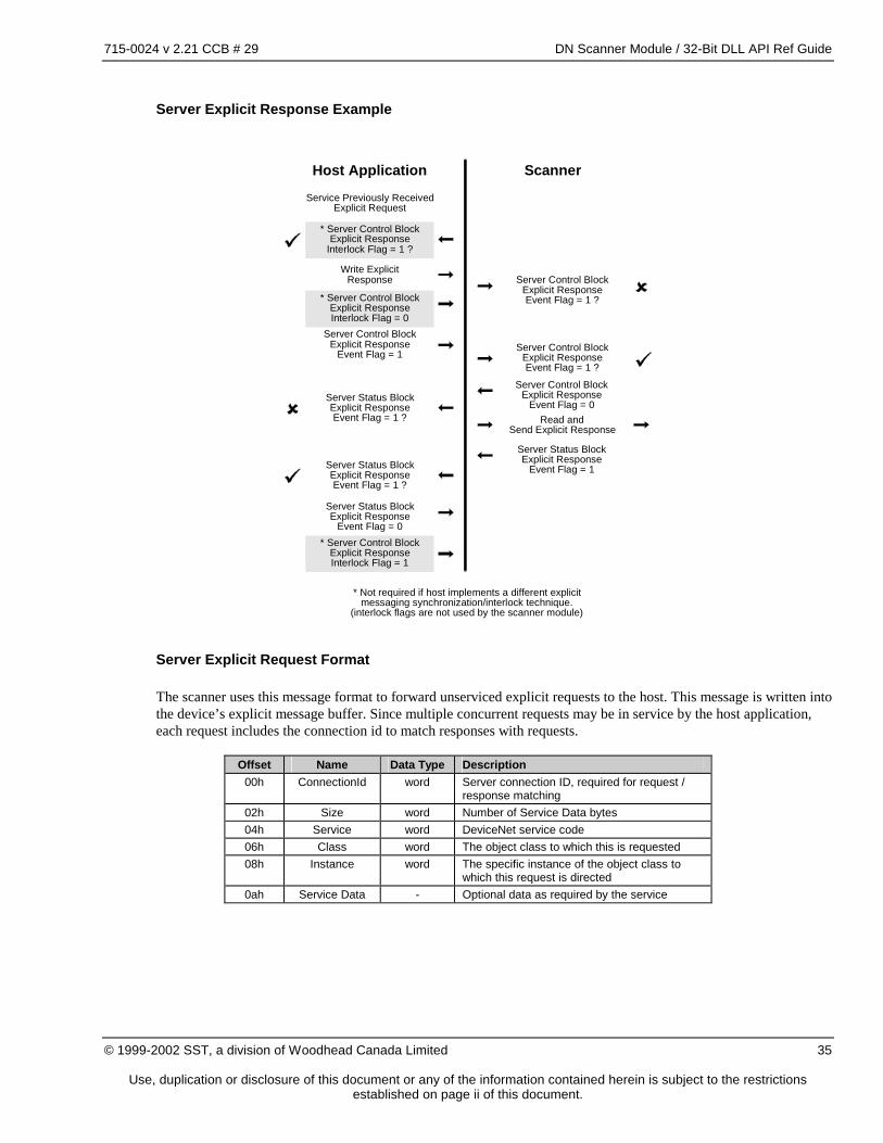
Server Explicit Response Example
* Not required if host implements a different explicitmessaging synchronization/interlock technique.
(interlock flags are not used by the scanner module)
Server Control BlockExplicit ResponseEvent Flag = 1 ?
Server Control BlockExplicit ResponseEvent Flag = 1 ?
* Server Control BlockExplicit Response
Interlock Flag = 1 ?
Service Previously ReceivedExplicit Request
Server Status BlockExplicit ResponseEvent Flag = 1 ?
Server Status BlockExplicit ResponseEvent Flag = 1 ?
Server Control BlockExplicit Response
Event Flag = 0
Server Status BlockExplicit Response
Event Flag = 1
Host Application Scanner
Write ExplicitResponse
Read andSend Explicit Response
Server Control BlockExplicit Response
Event Flag = 1
* Server Control BlockExplicit ResponseInterlock Flag = 1
* Server Control BlockExplicit ResponseInterlock Flag = 0
Server Status BlockExplicit Response
Event Flag = 0
Server Explicit Request Format
The scanner uses this message format to forward unserviced explicit requests to the host. This message is written into the device’s explicit message buffer. Since multiple concurrent requests may be in service by the host application, each request includes the connection id to match responses with requests.
Offset Name Data Type Description
00h ConnectionId word Server connection ID, required for request / response matching
02h Size word Number of Service Data bytes 04h Service word DeviceNet service code 06h Class word The object class to which this is requested 08h Instance word The specific instance of the object class to
which this request is directed 0ah Service Data - Optional data as required by the service
715-0024 v 2.21 CCB # 29 DN Scanner Module / 32-Bit DLL API Ref Guide
Use, duplication or disclosure of this document or any of the information contained herein is subject to the restrictions established on page ii of this document.
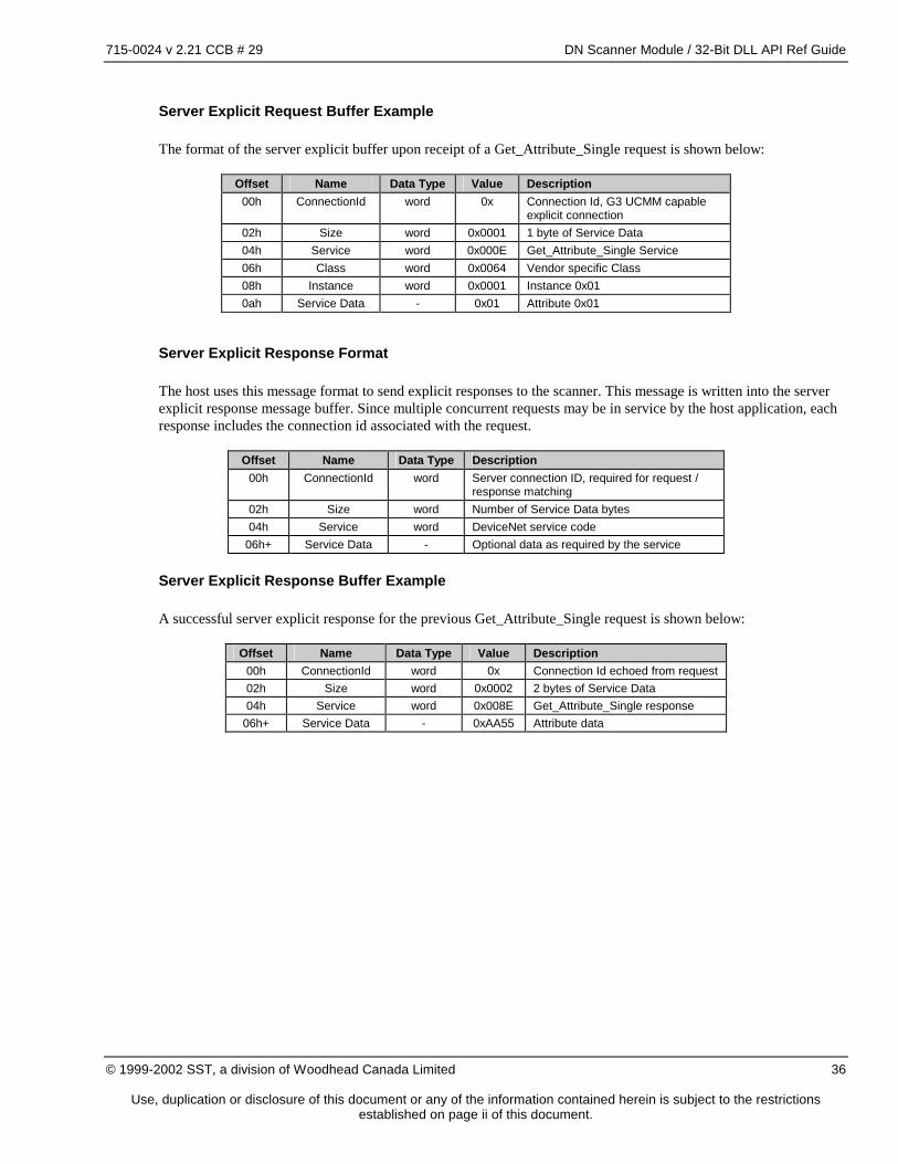
Server Explicit Request Buffer Example
The format of the server explicit buffer upon receipt of a Get_Attribute_Single request is shown below:
Offset Name Data Type Value Description 00h ConnectionId word 0x Connection Id, G3 UCMM capable
explicit connection 02h Size word 0x0001 1 byte of Service Data 04h Service word 0x000E Get_Attribute_Single Service 06h Class word 0x0064 Vendor specific Class 08h Instance word 0x0001 Instance 0x01 0ah Service Data - 0x01 Attribute 0x01
Server Explicit Response Format
The host uses this message format to send explicit responses to the scanner. This message is written into the server explicit response message buffer. Since multiple concurrent requests may be in service by the host application, each response includes the connection id associated with the request.
Offset Name Data Type Description
00h ConnectionId word Server connection ID, required for request / response matching
02h Size word Number of Service Data bytes 04h Service word DeviceNet service code
06h+ Service Data - Optional data as required by the service
Server Explicit Response Buffer Example
A successful server explicit response for the previous Get_Attribute_Single request is shown below:
Offset Name Data Type Value Description 00h ConnectionId word 0x Connection Id echoed from request 02h Size word 0x0002 2 bytes of Service Data 04h Service word 0x008E Get_Attribute_Single response
06h+ Service Data - 0xAA55 Attribute data
715-0024 v 2.21 CCB # 29 DN Scanner Module / 32-Bit DLL API Ref Guide
Use, duplication or disclosure of this document or any of the information contained herein is subject to the restrictions established on page ii of this document.
3.11 Connection Path Buffer
A connection path buffer is used to contain Connection Paths associated with client and/or server connections. An independent connection path buffer is used for each server I/O connection (if supported) and each supported I/O connection for each device. These buffers are allocated within the memory pool in the same manner as I/O data buffers.
3.11.1 Connection Path Format
This format is used to represent variable-length connection path strings:
Offset Name Data Type Description 0 MaximumSize word Connection path buffer size
Maximum number of bytes in connection path
2 Size word Number of bytes in connection path
4+ Path byte... Connection path The minimum connection path buffer size is 4 bytes. In this case both MaximumSize and Size must be 0 (no bytes available for Path).
3.12 Event Notification Queue
The event notification queue is provided to minimize the overhead required to pass scanner events to the host application. Each event may be individually enabled for notification, reducing the number of interrupts that must be processed by the host application to the actual number of events being monitored. The event notification queue is optional and the default behavior of all events is notification disabled.
3.12.1 Event Queue Operation
1. Scanner processes an internal event which results in a host interface event. 2. Scanner checks appropriate Control Block event queue enable flag. If the flag is false the scanner takes no
further action. 3. Scanner writes event source and ID to the Event Queue Entry referenced by the QueueIn offset. 4. Scanner updates the local copy of QueueIn to point to the next queue entry wrapping around at end of queue
area. If the new value for QueueIn is equal to QueueOut, the queue is full and the scanner asserts the Queue Overflow
flag in Event Queue Status, does not update QueueIn and takes no further action. 5. Scanner writes the updated QueueIn and generates an Event Queue interrupt. 6. Host Application receives the event queue interrupt or some other trigger mechanism such as a cyclic timer. 7. Host Application compares the QueueIn and QueueOut offsets in the Event Queue. If they are equal, the event
queue is empty. 8. Host Application reads the event source and ID from the Event Queue Entry referenced by the QueueOut offset. 9. Host Application updates QueueOut to point to the next queue entry wrapping around at end of queue area. 10. Host may optionally repeat steps 7-9 until the queue is empty.
715-0024 v 2.21 CCB # 29 DN Scanner Module / 32-Bit DLL API Ref Guide
Use, duplication or disclosure of this document or any of the information contained herein is subject to the restrictions established on page ii of this document.
4 Shared Memory Interface
4.1 Introduction
The interface between DNSCAN and the host application is implemented using shared memory and one interrupt signal in each direction.
4.2 Host Interface Memory
The 5136-DN card has 16 kbytes of shared RAM accessible to the host application. The layout of this memory is illustrated in the following table:
Each type of 5136-DN card has 16K of RAM conforming to this memory map. However, the way this memory is mapped into the host system’s address space is different for each type of card. Please refer to the Hardware Reference Guide for memory access details.
715-0024 v 2.21 CCB # 29 DN Scanner Module / 32-Bit DLL API Ref Guide
Use, duplication or disclosure of this document or any of the information contained herein is subject to the restrictions established on page ii of this document.
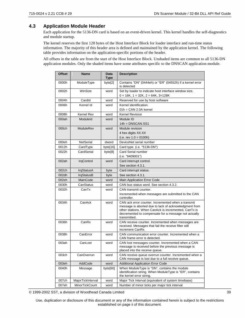
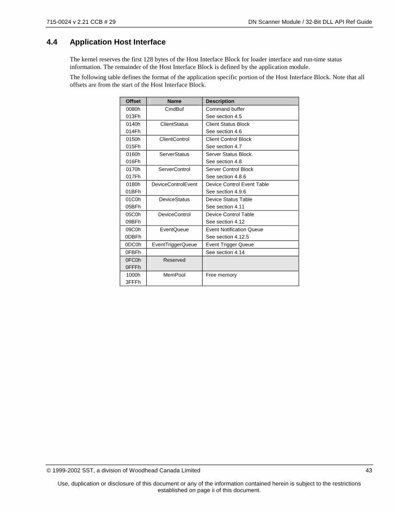
4.3 Application Module Header Each application for the 5136-DN card is based on an event-driven kernel. This kernel handles the self-diagnostics and module startup. The kernel reserves the first 128 bytes of the Host Interface Block for loader interface and run-time status information. The majority of this header area is defined and maintained by the application kernel. The following table provides information on the application-specific portions of the header. All offsets in the table are from the start of the Host Interface Block. Unshaded items are common to all 5136-DN application modules. Only the shaded items have some attributes specific to the DNSCAN application module.
Offset Name Data
Type Description
0000h ModuleType byte[2] Contains "DN" (0444eh) or "ER" (04552h) if a kernel error is detected
0002h WinSize word Set by loader to indicate host interface window size. 0 = 16K, 1 = 32K, 2 = 64K, 3=128K
0004h CardId word Reserved for use by host software 0006h Kernel Id word Kernel identification.
01h = CAN 2.0A kernel 0008h Kernel Rev word Kernel Revision 000ah ModuleId word Module ID
14h = DNSCAN.SS1 000ch ModuleRev word Module revision
4 hex digits XX.XX (i.e. rev 1.0 = 0100h)
000eh NetSerial dword DeviceNet serial number 0012h CardType byte[16] Card type. (i.e. "5136-DN") 0022h CardSerial byte[8] Card Serial number
(i.e. "9409001") 002ah IrqControl word Card interrupt control.
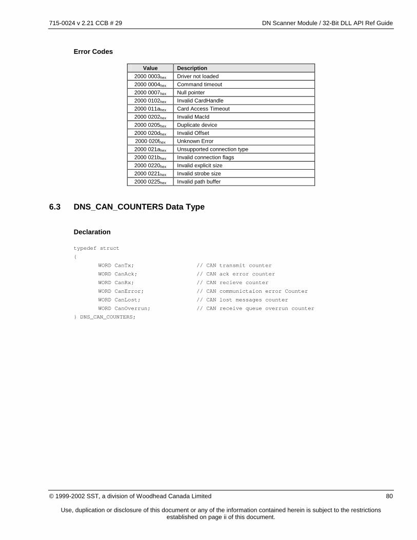
See section 4.3.1. 002ch IrqStatusA byte Card interrupt status. 002dh IrqStatusB byte See section 4.3.1. 002eh MainCode word Main Application Error Code 0030h CanStatus word CAN bus status word. See section 4.3.2. 0032h CanTx word CAN transmit counter.
Incremented when messages are submitted to the CAN controller.
0034h CanAck word CAN ack error counter. Incremented when a transmit message is aborted due to lack of acknowledgment from other stations. When CanAck is incremented, CanTx is decremented to compensate for a message not actually transmitted.
0036h CanRx word CAN receive counter. Incremented when messages are received. Messages that fail the receive filter still increment CanRx.
0038h CanError word CAN communication error counter. Incremented when a CAN frame error is detected.
003ah CanLost word CAN lost messages counter. Incremented when a CAN message is received before the previous message is placed into the receive queue.
003ch CanOverrun word CAN receive queue overrun counter. Incremented when a CAN message is lost due to a full receive queue.
003eh AddCode word Additional Application Error Code 0040h Message byte[60] When ModuleType is "DN", contains the module
identification string. When ModuleType is "ER”, contains the kernel error string.
007ch MajorTickInterval word Major Tick Interval (equivalent of system timebase) 007eh MinorTickCount word Number of minor ticks per major tick interval
715-0024 v 2.21 CCB # 29 DN Scanner Module / 32-Bit DLL API Ref Guide
Use, duplication or disclosure of this document or any of the information contained herein is subject to the restrictions established on page ii of this document.
4.3.1 IRQ Control / Status
The IRQ control and status areas are used to implement up to 8 logical interrupts using only 1 physical interrupt signal.
IRQ Control Word (002Ah)
The IRQ Control Word contains 8 bits which are used to enable the generation of a physical interrupt for each of up to 8 logical interrupt sources. This word is written by the host and not written by the scanner.
Bit
Offset 7 6 5 4 3 2 1 0 002Ah Reserved QE BS CM 002Bh Reserved
QE Queue Event (see section 4.12.5) BS Bus status changed (see section 4.3.2) CM Command acknowledge (see section 4.5)
IRQ Status Byte A/B (002Ch / 002Dh)
The IRQ Status Bytes each contain 8 bits which are set when each of up to 8 logical interrupts occur. The IRQ Status Bytes reflect logical interrupts even if the physical interrupt has been disabled via the IRQ Control Word. These bytes are written by the scanner and the host application. The IRQ access protocol described below must be followed to avoid missed interrupts.
Bit
Offset 7 6 5 4 3 2 1 0 002Ch Reserved QE BS CM 002Dh Reserved QE BS CM
QE Queue Event (see section 4.12.5) BS Bus status changed (see section 4.3.2) CM Command acknowledge (see section 4.5)
IRQ Status Access Protocol
To avoid inadvertently clearing interrupt status flags the host application must: 1. Read IrqStatusA and store the result in temporary variable ‘A’. 2. Clear relevant bits in IrqStatusA. 3. Read IrqStatusB and store the result in temporary variable ‘B’. 4. Clear relevant bits in IrqStatusB. 5. Logically OR temporary variables ‘A’ and ‘B’ to determine IRQ status flags.
NOTE: The only possible result of an access collision between the scanner and the host application is an interrupt status flag remaining set after the host has attempted to clear it.
715-0024 v 2.21 CCB # 29 DN Scanner Module / 32-Bit DLL API Ref Guide
Use, duplication or disclosure of this document or any of the information contained herein is subject to the restrictions established on page ii of this document.
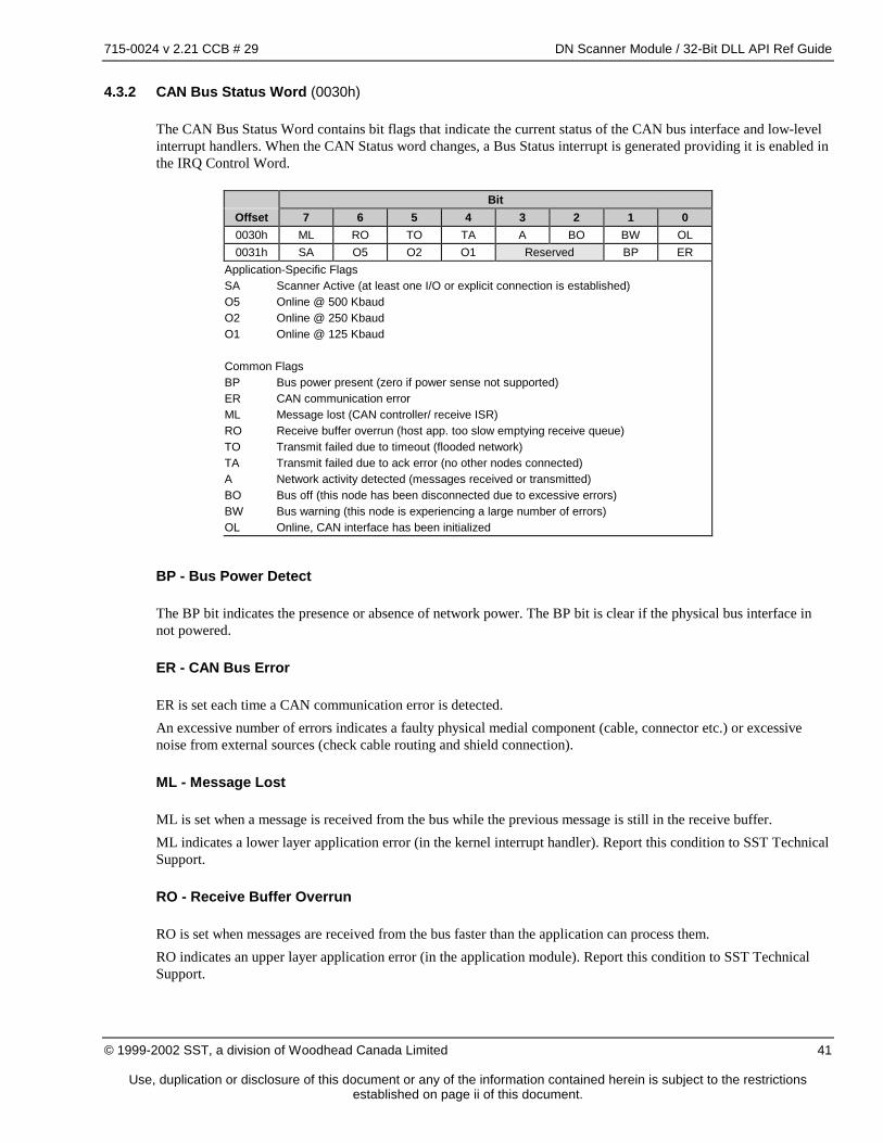
4.3.2 CAN Bus Status Word (0030h)
The CAN Bus Status Word contains bit flags that indicate the current status of the CAN bus interface and low-level interrupt handlers. When the CAN Status word changes, a Bus Status interrupt is generated providing it is enabled in the IRQ Control Word.
Bit
Offset 7 6 5 4 3 2 1 0 0030h ML RO TO TA A BO BW OL 0031h SA O5 O2 O1 Reserved BP ER
Application-Specific Flags SA Scanner Active (at least one I/O or explicit connection is established) O5 Online @ 500 Kbaud O2 Online @ 250 Kbaud O1 Online @ 125 Kbaud Common Flags BP Bus power present (zero if power sense not supported) ER CAN communication error ML Message lost (CAN controller/ receive ISR) RO Receive buffer overrun (host app. too slow emptying receive queue) TO Transmit failed due to timeout (flooded network) TA Transmit failed due to ack error (no other nodes connected) A Network activity detected (messages received or transmitted) BO Bus off (this node has been disconnected due to excessive errors) BW Bus warning (this node is experiencing a large number of errors) OL Online, CAN interface has been initialized
BP - Bus Power Detect
The BP bit indicates the presence or absence of network power. The BP bit is clear if the physical bus interface in not powered.
ER - CAN Bus Error
ER is set each time a CAN communication error is detected. An excessive number of errors indicates a faulty physical medial component (cable, connector etc.) or excessive noise from external sources (check cable routing and shield connection).
ML - Message Lost
ML is set when a message is received from the bus while the previous message is still in the receive buffer. ML indicates a lower layer application error (in the kernel interrupt handler). Report this condition to SST Technical Support.
RO - Receive Buffer Overrun
RO is set when messages are received from the bus faster than the application can process them. RO indicates an upper layer application error (in the application module). Report this condition to SST Technical Support.
715-0024 v 2.21 CCB # 29 DN Scanner Module / 32-Bit DLL API Ref Guide
Use, duplication or disclosure of this document or any of the information contained herein is subject to the restrictions established on page ii of this document.
TO - Transmit Timeout
TO is set when a pending transmission is incomplete within 25-50ms. TO indicates excessive message traffic at a higher priority than the aborted message.
TA - Transmit Ack Error
TA is set when a pending transmission is not acknowledged within 25-50ms. TA indicates that no other nodes are present (or on-line) on the network
A - Network activity detected
A is set when any message is transmitted or received.
BO - Bus off
BO is set when an excessive number of communication errors is detected and the CAN chip automatically goes off-line. BO is cleared when the CAN interface is re-initialized. BO indicates a serious communication fault such as incorrect baud rate or physical layer error (short, open etc). To recover from a bus off condition the application can issue the following command sequence: STOP_SCAN, OFFLINE, ONLINE, START_SCAN.
BW - Bus warning
BW is set when an abnormal number of communication errors is detected and the CAN chip stops transmitting error frames. BW is cleared when the error count returns to normal levels or the CAN interface is re-initialized. BW indicates a potentially serious communication fault such as out-of-tolerance baud rate or physical layer error (electrical noise, signal attenuation, intermittent connections etc).
OL - Online
OL indicates that the CAN interface has been initialized and is ready to communicate.
715-0024 v 2.21 CCB # 29 DN Scanner Module / 32-Bit DLL API Ref Guide
Use, duplication or disclosure of this document or any of the information contained herein is subject to the restrictions established on page ii of this document.
4.4 Application Host Interface
The kernel reserves the first 128 bytes of the Host Interface Block for loader interface and run-time status information. The remainder of the Host Interface Block is defined by the application module. The following table defines the format of the application specific portion of the Host Interface Block. Note that all offsets are from the start of the Host Interface Block.
Offset Name Description 0080h CmdBuf Command buffer 013Fh See section 4.5 0140h ClientStatus Client Status Block 014Fh See section 4.6 0150h ClientControl Client Control Block 015Fh See section 4.7 0160h ServerStatus Server Status Block. 016Fh See section 4.8 0170h ServerControl Server Control Block 017Fh See section 4.8.6 0180h DeviceControlEvent Device Control Event Table 01BFh See section 4.9.6 01C0h DeviceStatus Device Status Table 05BFh See section 4.11 05C0h DeviceControl Device Control Table 09BFh See section 4.12 09C0h EventQueue Event Notification Queue 0DBFh See section 4.12.5 0DC0h EventTriggerQueue Event Trigger Queue 0FBFh See section 4.14 0FC0h Reserved 0FFFh 1000h MemPool Free memory 3FFFh
715-0024 v 2.21 CCB # 29 DN Scanner Module / 32-Bit DLL API Ref Guide
Use, duplication or disclosure of this document or any of the information contained herein is subject to the restrictions established on page ii of this document.
4.5 Command Buffer
Offset: 0080h - 013Fh The Command Buffer is the main initialization interface between the host application and DNSCAN. Commands are written to the Command Buffer to initialize, start and shut down the scanner. The parameter area of the Command Buffer differs for each command. Command results and reply data (if any) are returned in the command buffer. The following sections describe the format of the command and reply for each command.
4.5.1 Sending a Command to DNSCAN
To send a command to DNSCAN:
1. Clear the command acknowledge flag (CM) in both IRQStatus bytes A and B. See section 4.3.1. 2. Write the command and the parameters (if required) to the Command Buffer (0080h). 3. Interrupt the card to execute the command. Refer to the Hardware Reference Guide for details on how to
interrupt the card. 4. Wait for the CM flag to appear in either IRQStatus bytes A or B (see section 4.3.1). This may be implemented with a physical interrupt or by polling the card interrupt flag. 5. Read the command status and reply data (if any) from the Command Buffer. See section 4.5.8.
The following table lists all commands supported by DNSCAN:
Command Value Description Timeout
DN_ONLINE 01h Initialize server parameters and go on-line 3 sec. DN_OFFLINE 02h Go offline 1 sec. ADD_DEVICE 03h Add a device to the device list. 1 sec. GET_DEVICE 04h Retrieve device configuration 1 sec.
DELETE_DEVICE 05h Remove a device from the device list 1 sec. START_SCAN 06h Establish client connections and start scanning
devices in device list 1 sec.
STOP_SCAN 07h Stop scanning and close client connections 1 sec. IO_ACTIVE 08h Set I/O active and start heartbeat timer 1 sec.
IO_IDLE 09h Set I/O idle and stop heartbeat timer 1 sec.
After the execution of any command, the Command Buffer contains either the command reply data as described in the following sections or an error status block. The format of the Error Status Block is:
Offset Name Data Type Description 0080h Command word Command with bit 15 set 0082h ErrCode word Error Code 0084h ErrCodeExt word Error code extension 0086h 013Fh
Reserved
Shaded items are reserved for future implementation
If any command fails, the Command Buffer contains the original command with bit 15 set and ErrCode indicates the nature of the error.
715-0024 v 2.21 CCB # 29 DN Scanner Module / 32-Bit DLL API Ref Guide
Use, duplication or disclosure of this document or any of the information contained herein is subject to the restrictions established on page ii of this document.
4.5.2 Command Errors
Error Code Value Description Command
0000h Reserved for host application use.
ERR_CMD 0001h Invalid command ERR_MAC 0002h Invalid MAC ID DN_ONLINE
ERR_BAUD 0003h Invalid baud rate DN_ONLINE ERR_DUPMAC 0004h Duplicate MAC ID DN_ONLINE ERR_DUPDEV 0005h Duplicate device ADD_DEVICE ERR_NODEV 0006h Device not found GET_DEVICE
DELETE_DEVICE ERR_OFF 0007h Bus offline START_SCAN
ERR_ACTIVE 0008h Scanner is active DN_OFFLINE ERR_NOTOFF 0009h Bus is not offline DN_ONLINE
ERR_SCAN 000Ah Scanner is running START_SCAN ERR_NOTSCAN 000Bh Scanner not running STOP_SCAN ERR_SCANOFF 000Ch Scanner is stopping START_SCAN
STOP_SCAN ERR_OFFSET 000Dh Invalid memory pool
offset ADD_DEVICE
ERR_BUSOFF 000Eh Bus fault DN_ONLINE ERR_CONNECTION_FLAGS 000Fh Invalid connection
flags combination ADD_DEVICE DN_ONLINE
ERR_EXP_BUFFER 0010h Invalid explicit buffer size
ADD_DEVICE DN_ONLINE
ERR_STROBE_BUFFER 0011h Invalid strobe buffer size (output must be 1)
Use, duplication or disclosure of this document or any of the information contained herein is subject to the restrictions established on page ii of this document.
4.5.3 DN_ONLINE Command
The DN_ONLINE command initializes the DeviceNet interface. Due to the duplicate MAC ID check, this command may take over 2 seconds to complete. The format of the command buffer for the DN_ONLINE command is:
Offset Name Data
TypeDescription
0080h Command word Command word DN_ONLINE = 01h
0082h MacId word Scanner MAC ID (0-63) Must not duplicate any other station
0086h ScanInterval word Default I/O update interval (used for Strobed I/O and Poll I/O connections with an I/O interval = 0)
0088h ReconnectInterval word Specifies the period to wait before attempting to reconnect when connection to a device is lost. 0 – Defaults to 10 seconds Valid Range 100 – 65535ms
008Ah Flags word Server connection flags 008Ch ExplicitRequestSize word Explicit request buffer size (bytes) 008Eh ExplicitRequestOffset word Offset to explicit request buffer 0090h ExplicitResponseSize word Explicit response buffer size (bytes) 0092h ExplicitResponseOffset word Offset to explicit response buffer 0094h Io1Interval word Future use, set to 0 0096h Output1Size word I/O connection 1 output size (bytes) 0098h Output1Offset word Offset to I/O connection 1 output data 009Ah Output1PathOffset word Offset to the I/O connection consumed path buffer 009Ch Input1Size word I/O connection 1 input size (bytes) 009Eh Input1Offset word Offset to I/O connection 1 input data 00A0h Input1PathOffset word Offset to the I/O connection produced path buffer 00A2h Io2Interval word Future use, set to 0 00A4h Output2Size word I/O connection 2 output size (bytes) 00A6h Output2Offset word Offset to I/O connection 2 output data 00A8h Output2PathOffset word Offset to the I/O connection consumed path buffer 00AAh Input2Size word I/O connection 2 input size (bytes) 00ACh Input2Offset word Offset to I/O connection 2 input data 00AEh Input2PathOffset word Offset to the I/O connection produced path buffer 00B0h 013Fh
Reserved
Shaded items are reserved for future implementation
The format of the command reply data for the DN_ONLINE command is:
Offset Name Data Type Description 0080h Command word Command ack.
DN_ONLINE = 01h Contains 8001h on error, see section 4.5.2.
0082h 013Fh
Reserved
715-0024 v 2.21 CCB # 29 DN Scanner Module / 32-Bit DLL API Ref Guide
Use, duplication or disclosure of this document or any of the information contained herein is subject to the restrictions established on page ii of this document.
Duplicate MAC Id Check
During execution of the DN_ONLINE command, DNSCAN performs a duplicate MAC ID check. If there is another station already using the same MAC ID, DNSCAN returns error code 0004h, ERR_DUPMAC. See section 4.5.2.
Bus Off Fault
If a fatal bus error (bus off) is detected during execution of the duplicate MAC ID check DNSCAN returns error code 000Eh, ERR_BUSOFF. See section 4.5.2. The most common cause of a fatal bus error is lack of network power.
4.5.4 DN_OFFLINE Command
The DN_OFFLINE command shuts down the DeviceNet interface. This command is not permitted when the scanner is active. The scanner must be shut down prior to going offline to ensure all client connections are closed. The format of the command buffer for the DN_OFFLINE command is:
Offset Name Data Type Description 0080h Command word Command word.
DN_OFFLINE = 02h 0082h 013Fh
Reserved
The format of the command reply data for the DN_OFFLINE command is:
Offset Name Data Type Description 0080h Command word Command ack.
DN_OFFLINE = 02h Contains 8002h on error, see section 4.5.2.
0082h 013Fh
Reserved
715-0024 v 2.21 CCB # 29 DN Scanner Module / 32-Bit DLL API Ref Guide
Use, duplication or disclosure of this document or any of the information contained herein is subject to the restrictions established on page ii of this document.
4.5.5 ADD_DEVICE Command
The ADD_DEVICE command adds a device configuration to the device list. See section 3.4 for device list parameter details. If the scanner is active, client connections are created and the device is scanned. The format of the command buffer for the ADD_DEVICE command is:
Offset Name Data
TypeDescription
0080h Command word Command word. ADD_DEVICE = 03h
0082h MacId word Device MAC ID (0-63) 0084h VendorId word Device Vendor ID 0086h DeviceType word Device Type 0088h ProductCode word Device Product Code 008Ah ProductionInhibitTime word For use with COS I/O connection only 008Ch Reserved word Future use, set to 0 008Eh Reserved word Future use, set to 0 0090h Flags word Connection Flags 0092h ExplicitSize word Explicit message buffer size (bytes) 0094h ExplicitOffset word Offset to explicit message buffer 0096h Io1Interval word Poll/COS/Cyclic I/O connection update rate 0098h Output1Size word I/O connection 1 output size (bytes) 009Ah Output1Offset word Offset to I/O connection 1 output data 009Ch Output1LocalPathOffset word Offset to the local I/O connection produced path buffer 009Eh Output1RemotePathOffset word Offset to the remote I/O connection consumed path buffer, set to 0 00A0h Input1Size word I/O connection 1 input size (bytes) 00A2h Input1Offset word Offset to I/O connection 1 input data 00A4h Input1LocalPathOffset word Offset to the local I/O connection consumed path buffer 00A6h Input1RemotePathOffset word Offset to the remote I/O connection consumed path buffer, set to 0 00A8h Io2Interval word Poll/COS/Cyclic I/O connection update rate 00AAh Output2Size word I/O connection 2 output size (bytes) 00ACh Output2Offset word Offset to I/O connection 2 output data 00AEh Output2LocalPathOffset word Offset to path buffer containing the local I/O connection produced
path 00B0h Output2RemotePathOffset word Offset to the remote I/O connection consumed path buffer, set to 0 00B2h Input2Size word I/O connection 2 input size (bytes) 00B4h Input2Offset word Offset to I/O connection 2 input data 00B6h Input2LocalPathOffset word Offset to the local I/O connection consumed path buffer 00B8h Input2RemotePathOffset word Offset to the remote I/O connection consumed path buffer, set to 0 00BAh 013Fh
Reserved
Shaded items are reserved for future implementation The format of the command reply data for the ADD_DEVICE command is:
Offset Name Data Type Description 0080h Command word Command ack
ADD_DEVICE = 03h Contains 8003h on error See section 4.5.2.
0082h 013Fh
Reserved
715-0024 v 2.21 CCB # 29 DN Scanner Module / 32-Bit DLL API Ref Guide
Use, duplication or disclosure of this document or any of the information contained herein is subject to the restrictions established on page ii of this document.
4.5.6 GET_DEVICE Command
The GET_DEVICE command retrieves a device configuration from the device list. The format of the command buffer for the GET_DEVICE command is:
Offset Name Data Type Description 0080h Command word Command word.
GET_DEVICE = 04h 0082h MacId word Device MAC ID (0-63) 0084h 013Fh
Reserved
See section 3.4 for device list parameter details. The format of the command reply data for the GET_DEVICE command is:
Offset Name Data
TypeDescription
0080h Command word Command ack GET_DEVICE = 04h Contains 8004h on error See section 4.5.2.
0082h MacId word Device MAC ID (0-63) 0084h VendorId word Device Vendor ID 0086h DeviceType word Device Type 0088h ProductCode word Device Product Code 008Ah ProductionInhibitTime word Product Inhibit Time for use with COS I/O connection only 008Ch Reserved word Future use 008Eh Reserved word Future use 0090h Flags word Connection Flags 0092h ExplicitSize word Explicit message buffer size (bytes) 0094h ExplicitOffset word Offset to explicit message buffer 0096h Io1Interval word Poll/COS/Cyclic I/O connection update rate 0098h Output1Size word I/O connection 1 output size (bytes) 009Ah Output1Offset word Offset to I/O connection 1 output data 009Ch Output1LocalPathOffset word Offset to the local I/O connection produced path buffer 009Eh Output1RemotePathOffset word Offset to the remote I/O connection consumed path buffer 00A0h Input1Size word I/O connection 1 input size (bytes) 00A2h Input1Offset word Offset to I/O connection 1 input data 00A4h Input1LocalPathOffset word Offset to the local I/O connection consumed path buffer 00A6h Input1RemotePathOffset word Offset to the remote I/O connection consumed path buffer 00A8h Io2Interval word Poll/COS/Cyclic I/O connection update rate 00AAh Output2Size word I/O connection 2 output size (bytes) 00ACh Output2Offset word Offset to I/O connection 2 output data 00AEh Output2LocalPathOffset word Offset to path buffer containing the local I/O connection produced
path 00B0h Output2RemotePathOffset word Offset to the remote I/O connection consumed path buffer 00B2h Input2Size word I/O connection 2 input size (bytes) 00B4h Input2Offset word Offset to I/O connection 2 input data 00B6h Input2LocalPathOffset word Offset to the local I/O connection consumed path buffer 00B8h Input2RemotePathOffset word Offset to the remote I/O connection consumed path buffer 00BAh 013Fh
Reserved
Shaded items are reserved for future implementation
715-0024 v 2.21 CCB # 29 DN Scanner Module / 32-Bit DLL API Ref Guide
Use, duplication or disclosure of this document or any of the information contained herein is subject to the restrictions established on page ii of this document.
4.5.7 DELETE_DEVICE Command
The DELETE_DEVICE command closes all related client connections and removes a device configuration from the device list. The format of the command buffer for the DELETE_DEVICE command is:
Offset Name Data Type Description 0080h Command word Command word.
DELETE_DEVICE = 05h 0082h MacId word Device MAC ID (0-63) 0084h 013Fh
Reserved
The format of the command reply data for the DELETE_DEVICE command is:
Offset Name Data Type Description 0080h Command word Command ack.
DELETE_DEVICE = 05h Contains 8005h on error See section 4.5.2
0082h 013Fh
Reserved
4.5.8 START_SCAN Command
The START_SCAN command starts the client function of the scanner. The format of the command buffer for the START_SCAN command is:
Offset Name Data Type Description 0080h Command word Command word.
START_SCAN = 06h 0082h 013Fh
Reserved
The format of the command reply data for the START_SCAN command is:
Offset Name Data Type Description 0080h Command word Command ack.
START_SCAN = 06h Contains 8006h on error, see section 4.5.2.
0082h 013Fh
Reserved
NOTE: If the scanner is active or is in the process of shutting down, DNSCAN returns a command error. See section 4.5.2.
715-0024 v 2.21 CCB # 29 DN Scanner Module / 32-Bit DLL API Ref Guide
Use, duplication or disclosure of this document or any of the information contained herein is subject to the restrictions established on page ii of this document.
4.5.9 STOP_SCAN Command
The STOP_SCAN command stops the client function of the scanner. The format of the command buffer for the STOP_SCAN command is:
Offset Name Data Type Description 0080h Command word Command word.
STOP_SCAN = 07h 0082h 013Fh
Reserved
The format of the command reply data for the STOP_SCAN command is:
Offset Name Data Type Description 0080h Command word Command ack.
STOP_SCAN = 07h Contains 8007h on error, see section 4.5.2.
0082h 013Fh
Reserved
NOTE: If the scanner is stopped or is in the process of shutting down, DNSCAN returns a command error. See section 4.5.2.
4.5.10 IO_ACTIVE Command
The IO_ACTIVE command sets the I/O mode to active and starts the application heartbeat timer. The format of the command buffer for the IO_ACTIVE command is:
Offset Name Data Type Description 0080h Command word Command word.
IO_ACTIVE = 08h 0082h Timeout word IoActive timeout delay (ms)
(zero = infinite timeout) 0084h 013Fh
Reserved
The format of the command reply data for the IO_ACTIVE command is:
Offset Name Data Type Description 0080h Command word Command ack.
IO_ACTIVE = 08h Contains 8008h on error See section 4.5.2.
0082h 013Fh
Reserved
NOTE: Once the IO_ACTIVE command has been executed, it must be executed at least once within the specified timeout period. If the timeout heartbeat timer expires before the next IO_ACTIVE command, the I/O mode is set to idle. See section 4.5.11. The next IO_ACTIVE command returns the I/O mode to active.
715-0024 v 2.21 CCB # 29 DN Scanner Module / 32-Bit DLL API Ref Guide
Use, duplication or disclosure of this document or any of the information contained herein is subject to the restrictions established on page ii of this document.
4.5.11 IO_IDLE Command
The IO_IDLE command sets the I/O mode to idle and stops the application heartbeat timer. The format of the command buffer for the IO_IDLE command is:
Offset Name Data Type Description 0080h Command word Command word
IO_IDLE = 09h 0082h 013Fh
Reserved
The format of the command reply data for the IO_IDLE command is:
Offset Name Data Type Description 0080h Command word Command ack
IO_IDLE = 09h Contains 8009h on error See section 4.5.2
0082h 013Fh
Reserved
NOTE: In I/O idle mode, all client and server I/O messages are forced to zero-length (transmit_idle). The device action to zero-length messages is defined by the device vendor.
715-0024 v 2.21 CCB # 29 DN Scanner Module / 32-Bit DLL API Ref Guide
Use, duplication or disclosure of this document or any of the information contained herein is subject to the restrictions established on page ii of this document.
4.6 Client Status Block
Offset: 0140h - 014Fh The Client Status Block provides status and event notification related to the client function of the scanner.
4.6.1 Client Status Block
Byte
Offset Acces
s Rule
Name Description
0140h R Status Code Client Status Code 0141h R Status Flags Client Status Flags 0142h R/W 1 Scan Event Flags Event flags related to the Group 2
Master/Slave I/O scan 0143h 014Fh
Reserved
1 Host may only write zero to this byte, and only if the byte is non-zero
C Prototype
typedef struct
{
unsigned char StatusCode;
unsigned char StatusFlags;
unsigned char ScanEventFlags;
unsigned char Reserved[13];
} CLIENT_STATUS;
4.6.2 Status Code
The Status Code indicates the current status of the client function of the scanner. This byte is written by the scanner and must not be written by the host.
Bit Flag Meaning
0 0 – Idle (not scanning) 1 – Active (scanning)
1 Tx Idle – If this bit is set the scanner is transmitting Idle output messages (zero length, no data) to all devices in the scan list. All server input messages (data sent to client) are also Idle (zero length, no data). See sections 4.5.10 and 4.5.11.
2 - 7
Reserved
715-0024 v 2.21 CCB # 29 DN Scanner Module / 32-Bit DLL API Ref Guide
Use, duplication or disclosure of this document or any of the information contained herein is subject to the restrictions established on page ii of this document.
4.6.3 Status Flags
The Status Flags report the status of the scanner’s client function. This byte is written by the scanner and must not be written by the host.
Bit Flag Description 0 IL Global I/O data input area interlock. The
scanner sets this flag when it is writing any device I/O data input areas
1 OL Global I/O data output area interlock. The scanner sets this flag when it is reading any device I/O data output areas
2-7 Reserved
4.6.4 Scan Event Flags
The Scan Event Flags inform the host of event occurrences related to the client function of the scanner. The host may only write 0 to this byte, and only if it is non-zero.
Bit Flag Description 0 S Start of Scan. This event is generated once per I/O
scan. This event is asynchronous to I/O data updates and does not replace the I/O data interlocks.
1-7 Reserved
715-0024 v 2.21 CCB # 29 DN Scanner Module / 32-Bit DLL API Ref Guide
Use, duplication or disclosure of this document or any of the information contained herein is subject to the restrictions established on page ii of this document.
4.7 Client Control Block
Offset: 0150h - 015Fh The Client Control Block provides control functions related to the client function of the scanner.
4.7.1 Client Control Block
Byte
Offset Access
Rule Name Description
0150h R/W Control Flags Client Control Flags 0151h 015Dh
Reserved
015Eh 015Fh
R/W Event Queue Enable Flags
Event notification queue enable flags
C Prototype
typedef struct
{
unsigned char ControlFlags;
unsigned char Reserved[13];
unsigned short EventQueueEnableFlags;
} CLIENT_CONTROL;
4.7.2 Control Flags
The control flags control the operation of the client function of the scanner. This byte is written by the host and is not written by the scanner.
Bit Flag Description 0 IL Global I/O data Input Interlock. The scanner
will not write any device input data areas when this bit is set.
1 OL Global I/O data output Interlock. The scanner will not read any device output data areas when this bit is set.
2-7 Reserved, set to 0
4.7.3 Event Queue Enable Flags
The Event Queue Enable Flags determine which client status events are posted into the event notification queue. When a client status event occurs, the event is posted into the event notification queue if the corresponding event queue enable flag is set.
Bit Flag Description 0 C Client status code changed event enable 1 Reserved, set to 0 2 S Client scan event enable
3-15 Reserved, set to 0
715-0024 v 2.21 CCB # 29 DN Scanner Module / 32-Bit DLL API Ref Guide
Use, duplication or disclosure of this document or any of the information contained herein is subject to the restrictions established on page ii of this document.
4.8 Server Status Block
Offset: 0160h - 016Fh The Server Status Block provides status and event notification related to the server function of the scanner.
NOTE The explicit message server functions in the Server Status Block support explicit request messages from either the Group 2 Master/Slave Connection Set or dynamic explicit connections to the scanner.
4.8.1 Server Status Block
Byte
Offset Access
Rule Name Description
0160h R Status Code Server Status Code 0161h R Status Flags Server Status Flags 0162h R/W 1 I/O 1 Event Flags Event flags related to the first I/O area. 0163h R/W 1 I/O 2 Event Flags Event flags related to the second I/O area. 0164h R/W 1 Explicit Request Event Flags Event flags related to the explicit request
message buffer. 0165h R/W 1 Explicit Response Event Flags Event flags related to the explicit response
message buffer. 0166h R AllocatedG2Connections Group 2 Server Connection Status 0167h 016Fh
Reserved
1 Host may only write zero to this byte, and only if the byte is non-zero
C Prototype
typedef struct
{
unsigned char StatusCode;
unsigned char StatusFlags;
unsigned char Io1EventFlags;
unsigned char Io2EventFlags;
unsigned char ExplicitRequestEventFlags;
unsigned char ExplicitResponseEventFlags;
unsigned char AllocatedG2Connections;
unsigned char Reserved[9];
} SERVER_STATUS;
4.8.2 Status Code
The Status Code reports the scanner’s server function. This byte is written by the scanner and must not be written by the host.
Status Meaning
00h Idle (Group 2 Master/Slave Connection Set not allocated) 01h Active (Group 2 Master/Slave Connection Set allocated)
02h - FFh
Reserved
715-0024 v 2.21 CCB # 29 DN Scanner Module / 32-Bit DLL API Ref Guide
Use, duplication or disclosure of this document or any of the information contained herein is subject to the restrictions established on page ii of this document.
4.8.3 Status Flags
The Status Flags report the status of the scanner’s server function. This byte is written by the scanner and must not be written by the host.
Bit Flag Description 0 EX Explicit Request Message Buffer Interlock. This flag is set when the
scanner is writing the explicit request message buffer. 1 I1 Input Area 1 Interlock. This flag is set when the scanner is writing the
first input area 2 I2 Input Area 2 Interlock. This flag is set when the scanner is writing the
second input area. 3 O1 Output Area 1 Interlock. This flag is set when the scanner is reading
the first output area 4 O2 Output Area 2 Interlock. This flag is set when the scanner is reading
the second output area 5 Z1 Output Area 1 receive_idle condition. This flag is set when the first
I/O connection receives a zero-length message and is cleared when a non-zero length message is consumed.
6 Z2 Output Area 2 receive_idle condition. This flag is set when the second I/O connection receives a zero-length message and is cleared when a non-zero length message is consumed.
7 Reserved
4.8.4 I/O Event Flags
The I/O Event Flags inform the host of event occurrences related to the server function of the scanner. Each I/O area has an independent event flag byte. The host may only write 0 to this byte, and only if it is non-zero.
Bit Flag Description 0 U Output data update. This bit is set every time a valid I/O message is
received from the I/O connection 1 Z Receive_Idle. This bit is set every time a zero-length I/O message is
received from the I/O connection 2-7 Reserved
4.8.5 Explicit Request Event Flags
The Explicit Request Event Flags inform the host of event occurrences related to the server Explicit Request Message Buffer. The host may only write 0 to this byte, and only if it is non-zero.
NOTE: Explicit requests forwarded to the server explicit message buffer may have been received by the Group 2 Master/Slave Connection Set explicit connection or a dynamic explicit connection opened through the UCMM.
Bit Flag Description 0 R Received explicit request. This bit is set when a received explicit
request is addressed to an object class not supported by the scanner. This bit is also set when an explicit request is addressed to an instance of the Identity Object other than 1. The host application must service the request and send a response.
1-7 Reserved
715-0024 v 2.21 CCB # 29 DN Scanner Module / 32-Bit DLL API Ref Guide
Use, duplication or disclosure of this document or any of the information contained herein is subject to the restrictions established on page ii of this document.
4.8.6 Explicit Response Event Flags
The Explicit Response Event Flags are used to inform the host of event occurrences related to the server Explicit Response Message Buffer. The host may only write 0 to this byte, and only if it is non-zero.
Bit Flag Description 0 S Explicit response sent. This bit is set when the scanner has
submitted the message in the explicit response buffer for transmission. This event signals the host that the scanner is ready for the next explicit response.
1-7 Reserved
4.8.7 Allocated G2 Connection Flags
The Allocated G2 connection flags indicated the currently allocated G2 connections for the server function of the scanner module.
Bit Offset 7 6 5 4 3 2 1 0
0 Res. AKS CYC COS Res. ST P EX Shaded options are reserved for future implementation Group 2 only I/O Connection Flags AKS Acknowledge suppress enabled CYC Cyclic I/O connection allocated COS Change-of-state I/O connection allocated ST Bit Strobed I/O connection allocated P Polled I/O connection allocated Group 2 Explicit Connection Flag EX Explicit connection allocated
715-0024 v 2.21 CCB # 29 DN Scanner Module / 32-Bit DLL API Ref Guide
Use, duplication or disclosure of this document or any of the information contained herein is subject to the restrictions established on page ii of this document.
4.9 Server Control Block
Offset: 0170h - 017Fh The Server Control Block provides event trigger and control functions related to the server function of the scanner.
NOTE: The explicit message server functions in the Server Control Block support explicit request messages from either the Group 2 Master/Slave Connection Set or dynamic explicit connections to the scanner.
4.9.1 Server Control Block
Byte
Offset Access
Rule Name Description
0170h W Control Flags Server Control Flags 0171h R/W 1 I/O 1 Event Flags Event flags related to the first I/O area. 0172h R/W 1 I/O 2 Event Flags Event flags related to the second I/O area. 0173h R/W 1 Explicit Request
Event Flags Event flags related to the explicit request message buffer.
0174h R/W 1 Explicit Response Event Flags
Event flags related to the explicit response message buffer.
0175h 017Dh
Reserved
017Eh 017Fh
R/W Event Queue Enable Flags
Event notification queue enable flags
1 Host may not write to this byte if it is non-zero
C Prototype
typedef struct
{
unsigned char ControlFlags;
unsigned char Io1EventFlags;
unsigned char Io2EventFlags;
unsigned char ExplicitRequestFlags;
unsigned char ExplicitResponseFlags;
unsigned char Reserved[9];
unsigned short EventQueueEnableFlags;
} SERVER_CONTROL;
715-0024 v 2.21 CCB # 29 DN Scanner Module / 32-Bit DLL API Ref Guide
Use, duplication or disclosure of this document or any of the information contained herein is subject to the restrictions established on page ii of this document.
4.9.2 Control Flags
The Control Flags control the server function of the scanner. This byte is written by the host and is not written by the scanner.
Bit Flag Description 0 EX Explicit Response Message Buffer Interlock. The scanner will not access
the explicit response message buffer when this bit is set. 1 I1 Input Area 1 Interlock. The scanner will not write the first input area when
this bit is set. 2 I2 Input Area 2 Interlock. The scanner will not write the second input area
when this bit is set. 3 O1 Output Area 1 Interlock. The scanner will not read the first output area
when this bit is set. 4 O2 Output Area 2 Interlock. The scanner will not read the second output area
when this bit is set. 5 Z1 Output Area 1 transmit_idle. When this flag is set the scanner produces
zero-length I/O messages on the first I/O connection 6 Z2 Output Area 2 transmit_idle. When this flag is set the scanner produces
zero-length I/O messages on the second I/O connection 7 Reserved
Shaded items are reserved for future implementation
4.9.3 I/O Event Flags
The I/O Event Flags are used to inform the scanner of event occurrences related to the server function of the scanner. Each I/O area has an independent event flag byte. The host may only write to this byte if it is zero.
Bit Flag Description 0 C Input Data Changed. The host sets this bit to notify the scanner of
changed input data. This event may trigger a message production depending on the I/O connection configuration.
1-7 Reserved Shaded items are reserved for future implementation
4.9.4 Explicit Request Event Flags
The Explicit Request Event Flags inform the scanner of event occurrences related to the server Explicit Request Message Buffer. The host may only to this byte if it is zero.
Bit Flag Description 0 R Explicit request received. This bit is set when the host application has
read the message in the explicit request buffer. This event signals the scanner that the host is ready for the next explicit request.
1-7 Reserved
715-0024 v 2.21 CCB # 29 DN Scanner Module / 32-Bit DLL API Ref Guide
Use, duplication or disclosure of this document or any of the information contained herein is subject to the restrictions established on page ii of this document.
4.9.5 Explicit Response Event Flags
The Explicit Response Event Flags inform the scanner of event occurrences related to the server Explicit Response Message Buffer. The host may only to this byte if it is zero.
Bit Flag Description 0 S Send Explicit Response. The application sets this flag after it has
processed an explicit request event and written an appropriate response to the explicit response message buffer.
1-7 Reserved
4.9.6 Event Queue Enable Flags
The event queue enable word determines which server status events are posted into the event notification queue. When a server status event occurs, the event is posted into the event notification queue if the corresponding event queue enable flag is set.
Bit Flag Description 0 C Server status code changed event enable 1 Reserved, set to 0 2 1 I/O area 1 event enable 3 2 I/O area 2 event enable 4 Q Explicit request event enable 5 R Explicit response event enable 6 CF Server G2 Connection Flags status event
enable 7-15 Reserved, set to 0
4.10 Device Control Event Table
Offset: 0180h - 01BFh The Device Control Event Table is an array of event flag bytes, one for each MAC ID. This table notifies the scanner which devices have pending control events.
Byte Offse
t
Access
Rule
Description
0180h R/W 1,2
Device Control Event Flag for MAC ID 0
0181h R/W 1,2
Device Control Event Flag for MAC ID 1
- - - 01BF
h R/W
1,2 Device Control Event Flag for MAC ID 63
1 Host only writes ‘1’, and only if byte is zero 2 Scanner only writes zero, and only if byte is non-zero
The host must write a ‘1’ to the Device Control Event Table when any event flags are written in the Device Control Table for the corresponding device. The host must not write to the Device Control Event Table if the value is already non-zero. The scanner writes zero to the Device Status Event Table before handling the event and clearing the event flag(s) in the Device Control Table.
715-0024 v 2.21 CCB # 29 DN Scanner Module / 32-Bit DLL API Ref Guide
Use, duplication or disclosure of this document or any of the information contained herein is subject to the restrictions established on page ii of this document.
4.11 Device Status Table
Offset: 01C0h - 05BFh The Device Status Table provides status and event notification related to the client function of the scanner. The Device Status Table is an array of DeviceStatus structures, one for each MAC ID. The first element corresponds to MAC ID 0.
4.11.1 Device Status Structure
Byte
Offset Access
Rule Name Description
0 R Status Code Device Status Code 1 R Status Flags Device Status Flags 2 R/W 1 I/O 1 Event Flags Event flags related to the first I/O area. 3 R/W 1 I/O 2 Event Flags Event flags related to the second I/O
area. 4 R/W 1 Explicit Event Flags Event flags related to the explicit
message buffer. 5-15 Reserved
1 Host may only write zero to this byte, and only if the byte is non-zero
C Prototype
typedef struct
{
unsigned char StatusCode;
unsigned char StatusFlags;
unsigned char Io1EventFlags;
unsigned char Io2EventFlags;
unsigned char ExplicitEventFlags;
unsigned char Reserved[11];
} DEVICE_STATUS;
715-0024 v 2.21 CCB # 29 DN Scanner Module / 32-Bit DLL API Ref Guide
Use, duplication or disclosure of this document or any of the information contained herein is subject to the restrictions established on page ii of this document.
4.11.2 Status Code
The status code indicates the status of the client connection to the device. This byte is written by the scanner and must not be written by the host.
Status Code
Status Meaning 00h Device not in device list 01h Device idle (not being scanned) 02h Device being scanned 03h Device timed-out 04h UCMM connection error 05h Master/Slave connection set is busy 06h Error allocating Master/Slave connection set 07h Invalid vendor id 08h Error reading vendor id 09h Invalid device type 0Ah Error reading device type 0Bh Invalid product code 0Ch Error reading product code 0Dh Invalid I/O connection 1 input size 0Eh Error reading I/O connection 1 input size 0Fh Invalid I/O connection 1 output size 10h Error reading I/O connection 1 output size 11h Invalid I/O connection 2 input size 12h Error reading I/O connection 2 input size 13h Invalid I/O connection 2 output size 14h Error reading I/O connection 2 output size 15h Error setting I/O connection 1 packet rate 16h Error setting I/O connection 2 packet rate 17h M/S connection set sync fault 18h Error setting Production Inhibit Time
19h - FFh
Reserved
715-0024 v 2.21 CCB # 29 DN Scanner Module / 32-Bit DLL API Ref Guide
Use, duplication or disclosure of this document or any of the information contained herein is subject to the restrictions established on page ii of this document.
4.11.3 Status Flags
The Status Flags inform host of the device connection status. This byte is written by the scanner and must not be written by the host.
Bit Flag Description 0 Reserved 1 I1 Input Area 1 Interlock. The scanner sets this flag when it is
writing the first input area 2 I2 Input Area 2 Interlock. The scanner sets this flag when it is
writing the second input area 3 O1 Output Area 1 Interlock. The scanner sets this flag when it
reading the first output area 4 O2 Output Area 2 Interlock. The scanner sets this flag when it is
reading the second output area 5 Z1 Input Area 1 receive_idle condition. This flag is set when the
first I/O connection receives a zero-length message and is cleared when a non-zero length message is consumed
6 Z2 Input Area 2 receive_idle condition. This flag is set when the second I/O connection receives a zero-length message and is cleared when a non-zero length message is consumed
7 Reserved
4.11.4 I/O Event Flags
The I/O Event Flags inform the host of event occurrences related to the client I/O areas. Each I/O area has an independent event flag byte.
Bit Flag Description 0 U Input data update. This bit is set every time a valid I/O
message is received from the I/O connection 1 Z Receive_Idle. This bit is set every time a zero-length
I/O message is received from the I/O connection 2-7 Reserved
4.11.5 Explicit Messaging Event Flags
The Explicit Messaging Event Flags inform the host of event occurrences related to the client Explicit Message Buffer.
Bit Flag Description 0 R Received explicit response. This bit is set when a
response to a previously transmitted explicit request is received.
1 RX Received excessive length explicit response. This bit has the same function as the R flag below, except it also indicates that the received explicit response has been truncated to fit the buffer.
2-7 Reserved
715-0024 v 2.21 CCB # 29 DN Scanner Module / 32-Bit DLL API Ref Guide
Use, duplication or disclosure of this document or any of the information contained herein is subject to the restrictions established on page ii of this document.
4.12 Device Control Table
Offset: 05C0h - 09BFh The Device Control Table provides event trigger and control functions related to the client function of the scanner. The Device Control Table is an array of DeviceControl structures, one for each MAC ID. The first element corresponds to MAC ID 0.
4.12.1 DeviceControl Structure
Byte
OffsetAccess
Rule Name Description
0 W Control Flags Device Control Flags 1 R/W 1 I/O 1 Event Flags Event flags related to the first I/O area. 2 R/W 1 I/O 2 Event Flags Event flags related to the second I/O area. 3 R/W 1 Explicit Event Flags Event flags related to the explicit message buffer.
4-13 R Reserved Reserved 14 15
W Event Queue Enable Flags
Event notification queue enable flags
1 Host may not write to this byte if it is non-zero
C Prototype
typedef struct
{
unsigned char ControlFlags;
unsigned char Io1EventFlags;
unsigned char Io2EventFlags;
unsigned char ExplicitEventFlags;
unsigned char Reserved[10];
unsigned short EventQueueEnableFlags;
} DEVICE_CONTROL;
715-0024 v 2.21 CCB # 29 DN Scanner Module / 32-Bit DLL API Ref Guide
Use, duplication or disclosure of this document or any of the information contained herein is subject to the restrictions established on page ii of this document.
4.12.2 Control Flags
The Control Flags control the client function of the scanner. This byte is written by the host and is not written by the scanner.
Bit Flag Description 0 EX Explicit Message Buffer Interlock. The scanner will not
access the explicit message buffer when this bit is set. 1 I1 Input Area 1 Interlock. The scanner will not read the first
input area when this bit is set. 2 I2 Input Area 2 Interlock. The scanner will not read the
second input area when this bit is set. 3 O1 Output Area 1 Interlock. The scanner will not write the
first output area when this bit is set. 4 O2 Output Area 2 Interlock. The scanner will not write the
second output area when this bit is set. 5 Z1 Output Area 1 transmit_idle. When this flag is set the
scanner produces zero-length I/O messages on the first I/O connection
6 Z2 Output Area 2 transmit_idle. When this flag is set the scanner produces zero-length I/O messages on the second I/O connection
7 Reserved Shaded items are reserved for future implementation
4.12.3 I/O Event Flags
The I/O Event Flags inform the scanner of client I/O event occurrences. Each I/O area has an independent event flag byte.
Bit Flag Description 0 C Output Data changed. The host sets this bit to notify
the scanner of changed output data. This event may trigger a message production depending on the I/O connection configuration.
1-7 Reserved, set to 0
4.12.4 Explicit Messaging Event Flags
The Explicit Messaging Event Flags are used to inform the scanner of event occurrences related to the Explicit Message Buffer associated with the client function of the scanner.
Bit Flag Description 0 S Send explicit request. The application sets this flag
to transmit the explicit request in the explicit message buffer.
1-7 Reserved, set to 0
715-0024 v 2.21 CCB # 29 DN Scanner Module / 32-Bit DLL API Ref Guide
Use, duplication or disclosure of this document or any of the information contained herein is subject to the restrictions established on page ii of this document.
4.12.5 Event Queue Enable Flags
The event queue enable word determines which device status events are posted into the event notification queue. When a device status event occurs, the event is posted into the event notification queue if the corresponding event queue enable flag is set.
Bit Flag Description 0 C Device status code changed event enable 1 Reserved, set to 0 2 1 I/O area 1 event enable 3 2 I/O area 2 event enable 4 R Explicit response event enable
5-15 Reserved, set to 0
4.13 Event Notification Queue
Offset: 09C0h - 0DBFh The event notification queue minimizes the overhead required to pass scanner events to the host application. Each event may be individually enabled for notification, reducing the number of interrupts that must be processed by the host application to the actual number of events being monitored.
Offset Name Data Type Description 0x09C0 QueueStatusA byte Queue status 0x09C1 QueueStatusB byte 0x09C2 QueueIn1,2 word Queue in offset, updated by the scanner only!
(0x09C6 initially) 0x09C4 QueueOut1,2 word Queue out offset, updated by the host
application only! (0x09C6 initially)
0x09C6 0x0DBF
Event Queue Event[509] Event queue entries
1 If QueueIn is equal to QueueOut the queue is empty. 2 If QueueIn + 2 is equal to QueueOut the queue is full.
4.13.1 Queue Status
The queue status bytes contain flags that indicate various error conditions. The scanner sets status bits and the host must clear the bits to detect the next occurrence.
Bit Flag Description 0 O Queue overrun, the scanner discarded an event
because the event queue was full 1-7 Reserved
715-0024 v 2.21 CCB # 29 DN Scanner Module / 32-Bit DLL API Ref Guide
Use, duplication or disclosure of this document or any of the information contained herein is subject to the restrictions established on page ii of this document.
Queue Status Access Rules
The scanner writes QueueStatusB first followed by QueueStatusA. The host application must: 1. Read QueueStatusA and store the result in temporary variable ‘A’. 2. Clear relevant bits in QueueStatusA. 3. Read QueueStatusB and store the result in temporary variable ‘B’. 4. Clear relevant bits in QueueStatusB. 5. Logically OR temporary variables ‘A’ and ‘B’ to determine queue status flags.
NOTE: The only possible result of an access collision between the scanner and the host application is a queue status flag remaining set after the host has attempted to clear it.
4.13.2 QueueIn
The QueueIn word contains the memory offset of the next event entry to be written by the scanner. The scanner updates QueueIn. The host must not write to QueueIn.
4.13.3 QueueOut
The QueueOut word contains the memory offset of the next event entry to be read by the host application. The scanner initializes QueueOut when the module is loaded and does not write to QueueOut at any other time.
4.13.4 Event Structure
The event structure contains one event in the event notification queue.
Offset Name Data Type Description 0 Source byte Event source 1 EventId byte EventId
Event Source
Source Description 0 Device 0 Event - -
63 Device 63 Event 64 Client Event 65 Server Event
66-255 Reserved
715-0024 v 2.21 CCB # 29 DN Scanner Module / 32-Bit DLL API Ref Guide
Use, duplication or disclosure of this document or any of the information contained herein is subject to the restrictions established on page ii of this document.
EventId
The event id is the byte offset from the start of the corresponding status block to the event flag byte.
Event ID Device Status Code Change Event 0 Device I/O 1 Event 2 Device I/O 2 Event 3 Device Explicit Messaging Event 4 Client Status Code Change Event 0 Client Scan Event 2 Server Status Code Change Event 0 Server I/O 1 Event 2 Server I/O 2 Event 3 Server Explicit Request Event 4 Server Explicit Response Event 5 Server Group 2 Connection Flags Status Change Event 6
4.14 Event Trigger Queue
Offset: 0DC0h – 0FBFh The event trigger queue minimizes the overhead required to pass application events to the scanner module. Using the event trigger queue reduces processing for the scanner module providing quicker event response and more stable repeatability.
Offset Name Data Type Description
0x0DC0 QueueStatusA byte Queue status 0x0DC1 QueueStatusB byte 0x0DC2 QueueIn1,2 Word Queue in offset, updated by the host
application only! (0x0DC4 initially)
0x0DC4 QueueOut1,2 Word Queue out offset, updated by the scanner only! (0x0DC4 initially)
0x0DC6 0x0FBF
Event Queue Event[506] Event queue entries
1 If QueueIn +1 is equal to QueueOut the queue is full. 2 If QueueIn is equal to QueueOut the queue is empty.
4.14.1 Queue Status
The queue status bytes contain flags that indicate various error conditions. The scanner sets status bits and the host must clear the bits to detect the next occurrence.
Bit Flag Description 0 I Invalid trigger event
1-7 Reserved
715-0024 v 2.21 CCB # 29 DN Scanner Module / 32-Bit DLL API Ref Guide
Use, duplication or disclosure of this document or any of the information contained herein is subject to the restrictions established on page ii of this document.
Queue Status Access Rules
The scanner writes QueueStatusB first followed by QueueStatusA. The host application must: 1. Read QueueStatusA and store the result in temporary variable ‘A’. 2. Clear relevant bits in QueueStatusA. 3. Read QueueStatusB and store the result in temporary variable ‘B’. 4. Clear relevant bits in QueueStatusB. 5. Logically OR temporary variables ‘A’ and ‘B’ to determine queue status flags.
NOTE: The only possible result of an access collision between the scanner and the host application is a queue status flag remaining set after the host has attempted to clear it.
4.14.2 QueueIn
The QueueIn word contains the memory offset of the next event entry to be written by the host application. The host application updates QueueIn. The scanner initializes QueueIn when the module is loaded and does not write to QueueIn at any other time.
4.14.3 QueueOut
The QueueOut word contains the memory offset of the next event entry to be read by the scanner module. The host application must not modify QueueOut.
4.14.4 Event Structure
The event structure contains one event in the event notification queue.
Offset Name Data Type Description 0 Source Byte Event source
Event Source
Source Description
0 Device 0 Event - -
63 Device 63 Event - Reserved for future use
65 Server Event 66 Command Event
66-255 Reserved
715-0024 v 2.21 CCB # 29 DN Scanner Module / 32-Bit DLL API Ref Guide
Use, duplication or disclosure of this document or any of the information contained herein is subject to the restrictions established on page ii of this document.
4.14.5 Using the Trigger Queue
To send a trigger event to DNSCAN: 1. Set the appropriate event flags in the Device/Server Control Table/Block as well as the Device Event Table. 2. Write the appropriate trigger event source to the Trigger Queue. 3. Interrupt the card to execute the trigger. Refer to the Hardware Reference Guide for details on how to interrupt
the card.
715-0024 v 2.21 CCB # 29 DN Scanner Module / 32-Bit DLL API Ref Guide
Use, duplication or disclosure of this document or any of the information contained herein is subject to the restrictions established on page ii of this document.
5 DeviceNet Scanner Module 32-Bit DLL
5.1 Introduction
DNSCAN32.DLL provides a common interface that abstracts the physical hardware to allow one application or DLL to interface with the DNSCAN module on different hardware platforms without changes. DNSCAN32.DLL is a 32-bit DLL for use with Windows 95 and Windows NT.
Use, duplication or disclosure of this document or any of the information contained herein is subject to the restrictions established on page ii of this document.
5.4 Typical Application Operation
This section describes the typical sequence of events for an application using the DeviceNet Scanner DLL.
Use, duplication or disclosure of this document or any of the information contained herein is subject to the restrictions established on page ii of this document.
Use, duplication or disclosure of this document or any of the information contained herein is subject to the restrictions established on page ii of this document.
Use, duplication or disclosure of this document or any of the information contained herein is subject to the restrictions established on page ii of this document.
Use, duplication or disclosure of this document or any of the information contained herein is subject to the restrictions established on page ii of this document.
Use, duplication or disclosure of this document or any of the information contained herein is subject to the restrictions established on page ii of this document.
// required)
ExplicitResponse = NOT_READY;
}
}}
}
DNS_StopScan( ... ) // stop scannning
DNS_Offline( ... ) // go offline
DNS_CloseCard( ... ) // close the card connection
DNS_FreeDriver() // unload the hardware driver DLL
}
715-0024 v 2.21 CCB # 29 DN Scanner Module / 32-Bit DLL API Ref Guide
Use, duplication or disclosure of this document or any of the information contained herein is subject to the restrictions established on page ii of this document.
6 DeviceNet Scanner DLL API
6.1 Introduction
This section defines the API (Application Programming Interface) for the DeviceNet Scanner DLL. All functions and data types are listed alphabetically.
6.2 DNS_AddDevice
Description
Add a device to the scan list. If the connection path offsets are non-zero they must be initialized prior to executing this command.
Related Topics
See sections 4.5.5 ADD_DEVICE Command, and section 6.24 DNS_InitializePathBuffer.
Use, duplication or disclosure of this document or any of the information contained herein is subject to the restrictions established on page ii of this document.
Use, duplication or disclosure of this document or any of the information contained herein is subject to the restrictions established on page ii of this document.
6.4 DNS_CloseCard
Description
Close a card connection. The specified card will be shut down and disabled if no other applications are connected.
Prototype
BOOL WINAPI DNS_CloseCard( DWORD CardHandle )
Arguments
Argument Description CardHandle The handle returned by DNS_OpenCard
Returns
Value Description TRUE Success FALSE Error, use GetLastError to retrieve error code
Error Codes
Value Description 2000 0003hex Driver not loaded 2000 0102hex Invalid CardHandle 2000 011ahex Card Access Timeout
715-0024 v 2.21 CCB # 29 DN Scanner Module / 32-Bit DLL API Ref Guide
Use, duplication or disclosure of this document or any of the information contained herein is subject to the restrictions established on page ii of this document.
6.5 DNS_DeleteDevice
Description
Remove a device from the scan list. All connections with the specified device are closed.
Related Topics
See section 4.5.7 DELETE_DEVICE Command.
Prototype
BOOL WINAPI DNS_DeleteDevice( DWORD CardHandle, WORD DeviceId )
Arguments
Argument Description CardHandle The handle returned by DNS_OpenCard
DeviceId Identifies device to be removed from the scan list
Returns
Value Description TRUE Success FALSE Error, use GetLastError to retrieve error code
Error Codes
Value Description 2000 0003hex Driver not loaded 2000 0004hex Command timeout 2000 0102hex Invalid CardHandle 2000 011ahex Card Access Timeout 2000 0206hex Device not found 2000 020fhex Unknown Error 2000 0211hex Device not configured 2000 021fhex Invalid DeviceId
715-0024 v 2.21 CCB # 29 DN Scanner Module / 32-Bit DLL API Ref Guide
Use, duplication or disclosure of this document or any of the information contained herein is subject to the restrictions established on page ii of this document.
6.6 DNS_DEVICE_CFG Data Type
Declaration
typedef struct
{
WORD MacId; // Device MacId
WORD VendorId; // Device Vendor Id
WORD DeviceType; // Device Device Type
WORD ProductCode; // Device Product Code
WORD ProductionInhibitTime; // Production Inhibit Time for use with COS I/O
// connections2
WORD Reserved2; // Reserved for future use
WORD Reserved3; // Reserved for future use
WORD Flags; // Connection flags
WORD ExplicitSize; // Device explicit buffer size
WORD ExplicitOffset; // Device explicit buffer offset
WORD Io1Interval; // I/O 1 connection interval
WORD Output1Size; // I/O 1 output buffer size
WORD Output1Offset; // I/O 1 output buffer offset
WORD Output1LocalPathOffset; // I/O 1 local output buffer path
// offset1
WORD Output1RemotePathOffset; // I/O 1 remote output buffer
// path offset1
WORD Input1Size; // I/O 1 input buffer size
WORD Input1Offset; // I/O 1 input buffer offset
WORD Input1LocalPathOffset; // I/O 1 local input buffer path
// offset1
WORD Input1RemotePathOffset; // I/O 1 remote input buffer path
// offset1
WORD Io2Interval; // I/O 2 connection interval
WORD Output2Size; // I/O 2 output buffer size
WORD Output2Offset; // I/O 2 output buffer offset
WORD Output2LocalPathOffset; // I/O 2 local output buffer path
// offset1
WORD Output2RemotePathOffset; // I/O 2 remote output buffer path
// offset1
WORD Input2Size; // I/O 2 input buffer size
WORD Input2Offset; // I/O 2 input buffer offset
WORD Input2LocalPathOffset; // I/O 2 local input buffer path
// offset1
WORD Input2RemotePathOffset; // I/O 2 remote input buffer path
// offset1
} DNS_DEVICE_CFG;
1 Path offsets must point to an initialized path buffer (see section 6.24) 2 This parameter is valid with change-of-state I/O connections only.
715-0024 v 2.21 CCB # 29 DN Scanner Module / 32-Bit DLL API Ref Guide
Use, duplication or disclosure of this document or any of the information contained herein is subject to the restrictions established on page ii of this document.
6.7 DNS_Driver
Description
Retrieve hardware driver version information. The driver version is returned in both numeric and human-readable string format.
Prototype
BOOL WINAPI DNS_Driver( TCHAR *Buffer, WORD *Version, DWORD Size )
Use, duplication or disclosure of this document or any of the information contained herein is subject to the restrictions established on page ii of this document.
6.8 DNS_EnumDrivers
Description
Enumerates available DeviceNet card configurations. This function can be called multiple times allowing the application to identify all available DeviceNet cards currently configured on the system.
Argument Description Index Index number of the driver to enumerate
lpName The driver name set by the function call Len Length of the lpName string.
When the function call returns, this will be set to the length of the driver name in lpName, including the null terminator. If no DeviceNet card configuration exists, or if the index has passed the last card configuration available, Len will be set to zero and the function will return TRUE.
Returns
Value Description TRUE Success FALSE Error, use GetLastError to retrieve error code
Error Codes
Value Description 2000 0003hex Driver not loaded 2000 0007hex Null pointer 2000 0100hex General failure
715-0024 v 2.21 CCB # 29 DN Scanner Module / 32-Bit DLL API Ref Guide
Use, duplication or disclosure of this document or any of the information contained herein is subject to the restrictions established on page ii of this document.
6.9 DNS_FreeDriver
Unload the Hardware Driver DLL. If no card connections are active the Driver DLL is unloaded
Prototype
BOOL WINAPI DNS_FreeDriver( void )
Arguments
This function has no arguments.
Returns
Value Description TRUE Success FALSE Error, use GetLastError to retrieve error code
Error Codes
Value Description 2000 0003hex Driver not loaded 2000 0008hex Connection Exists
715-0024 v 2.21 CCB # 29 DN Scanner Module / 32-Bit DLL API Ref Guide
Use, duplication or disclosure of this document or any of the information contained herein is subject to the restrictions established on page ii of this document.
6.10 DNS_GetBusStatus
Description
Get the CAN bus status word.
Related Topics
See section 4.3.2 CAN Bus Status Word (0030h).
Prototype
BOOL WINAPI DNS_GetBusStatus( DWORD CardHandle, WORD *BusStatus )
Arguments
Argument Description CardHandle The handle returned by DNS_OpenCard BusStatus Pointer to word to receive bus status flags
Returns
Value Description TRUE Success FALSE Error, use GetLastError to retrieve error code
Error Codes
Value Description 2000 0003hex Driver not loaded 2000 0007hex Null pointer 2000 0102hex Invalid CardHandle 2000 011ahex Card Access Timeout
715-0024 v 2.21 CCB # 29 DN Scanner Module / 32-Bit DLL API Ref Guide
Use, duplication or disclosure of this document or any of the information contained herein is subject to the restrictions established on page ii of this document.
Use, duplication or disclosure of this document or any of the information contained herein is subject to the restrictions established on page ii of this document.
Use, duplication or disclosure of this document or any of the information contained herein is subject to the restrictions established on page ii of this document.
6.13 DNS_GetClientEvent
Description
Retrieve the specified client status block event flags.
Use, duplication or disclosure of this document or any of the information contained herein is subject to the restrictions established on page ii of this document.
6.14 DNS_GetClientStatus
Description
Get the status information for the client function of the scanner.
Use, duplication or disclosure of this document or any of the information contained herein is subject to the restrictions established on page ii of this document.
6.15 DNS_GetDevice
Description
Read a device configuration from the scan list.
Related Topics
See section 4.5.6 GET_DEVICE Command.
Prototype
BOOL WINAPI DNS_GetDevice( DWORD CardHandle, WORD DeviceId, DNS_DEVICE_CFG *DeviceCfg )
Arguments
Argument Description CardHandle The handle returned by DNS_OpenCard
DeviceId Identifies device to be retrieved from the scan list DeviceCfg Device configuration block (see section 0
DNS_DEVICE_CFG Data Type) Destination of device configuration data from scan list
Returns
Value Description TRUE Success FALSE Error, use GetLastError to retrieve error code
Errors
Value Description 2000 0003hex Driver not loaded 2000 0004hex Command timeout 2000 0007hex Null pointer 2000 0102hex Invalid CardHandle 2000 011ahex Card Access Timeout 2000 0206hex Device not found 2000 020fhex Unknown Error 2000 0211hex Device not configured 2000 021fhex Invalid DeviceId
715-0024 v 2.21 CCB # 29 DN Scanner Module / 32-Bit DLL API Ref Guide
Use, duplication or disclosure of this document or any of the information contained herein is subject to the restrictions established on page ii of this document.
6.16 DNS_GetDeviceEvent
Description
Retrieve the device event flags for the specified event area. See the DeviceNet Scanner Module Reference Guide for more information.
Related Topics
See section 4.11Device Status Table.
Prototype
BOOL WINAPI DNS_GetDeviceEvent( DWORD CardHandle, WORD DeviceId, BYTE EventId,
BYTE *DeviceEvent )
Arguments
Argument Description CardHandle The handle returned by DNS_OpenCard
DeviceId Identifies device to be accessed EventId Indicates the event to be retrieved (see EventId table below)
DeviceEvent Buffer to contain device event flags
EventId
Value Name Description 0 Reserved 1 DNS_IO1_EVENT I/O area 1 events 2 DNS_IO2_EVENT I/O area 2 events 3 DNS_EXP_EVENT Explicit events
4-0xff Reserved
Returns
Value Description TRUE Success FALSE Error, use GetLastError to retrieve error code
Errors
Value Description 2000 0003hex Driver not loaded 2000 0007hex Null pointer 2000 0102hex Invalid CardHandle 2000 011ahex Card Access Timeout 2000 0211hex Device not configured 2000 0212hex Invalid Event Id 2000 021fhex Invalid DeviceId 2000 0222hex Connection not configured
715-0024 v 2.21 CCB # 29 DN Scanner Module / 32-Bit DLL API Ref Guide
Use, duplication or disclosure of this document or any of the information contained herein is subject to the restrictions established on page ii of this document.
6.17 DNS_GetDevicePath
Description
Retrieve the local or remote path for the specified device.
Related Topics
See section 3.11 Connection Path Buffer.
Prototype
BOOL WINAPI DNS_GetDevicePath( DWORD CardHandle, WORD DeviceId, BYTE PathId,
WORD *MaxPathLength, WORD *PathLength, BYTE *Buffer )
Arguments
Argument Description CardHandle The handle returned by DNS_OpenCard
DeviceId Identifies device to be accessed PathId Indicates the path information to be retrieved (see PathId table below)
MaxPathLength Contains the maximum path length upon return PathLength Initially contains the size of Buffer
On return contains the path length on success, 0 if path was not configured, or the required size if Buffer is too small (error 2000 0214hex)
Buffer Buffer to contain path
PathId
Value Name Description 0 DNS_OUTPUT1_PATH Local output 1 path 1 DNS_INPUT1_PATH Local input 1 path 2 DNS_OUTPUT2_PATH Local output 2 path 3 DNS_INPUT2_PATH Local input 2 path 4 DNS_REMOTE_OUTPUT1_PATH Remote output 1 path 5 DNS__REMOTE_INPUT1_PATH Remote input 1 path 6 DNS_REMOTE_OUTPUT2_PATH Remote output 2 path 7 DNS_REMOTE_INPUT2_PATH Remote input 2 path
8-0xff Reserved
Returns
Value Description TRUE Success FALSE Error, use GetLastError to retrieve error code
715-0024 v 2.21 CCB # 29 DN Scanner Module / 32-Bit DLL API Ref Guide
Use, duplication or disclosure of this document or any of the information contained herein is subject to the restrictions established on page ii of this document.
Errors
Value Description 2000 0003hex Driver not loaded 2000 0007hex Null pointer 2000 0102hex Invalid CardHandle 2000 011ahex Card Access Timeout 2000 0211hex Device not configured 2000 0214hex Invalid data buffer size 2000 021fhex Invalid DeviceId 2000 0223hex Invalid PathId
715-0024 v 2.21 CCB # 29 DN Scanner Module / 32-Bit DLL API Ref Guide
Use, duplication or disclosure of this document or any of the information contained herein is subject to the restrictions established on page ii of this document.
6.18 DNS_GetDeviceStatus
Description
Get the status information for a specific device.
Related Topics
See section 4.11 Device Status Table.
Prototype
BOOL WINAPI DNS_GetDeviceStatus( DWORD CardHandle, WORD DeviceId, DNS_STATUS *DeviceStatus )
Arguments
Argument Description CardHandle The handle returned by DNS_OpenCard
DeviceId Identifies the device to be accessed DeviceStatus Buffer to contain device status information.
(see section 6.46 DNS_STATUS Data Type)
Returns
Value Description TRUE Success FALSE Error, use GetLastError to retrieve error code
Errors
Value Description 2000 0003hex Driver not loaded 2000 0007hex Null pointer 2000 0102hex Invalid CardHandle 2000 011ahex Card Access Timeout 2000 0211hex Device not configured 2000 021fhex Invalid DeviceId
715-0024 v 2.21 CCB # 29 DN Scanner Module / 32-Bit DLL API Ref Guide
Use, duplication or disclosure of this document or any of the information contained herein is subject to the restrictions established on page ii of this document.
Use, duplication or disclosure of this document or any of the information contained herein is subject to the restrictions established on page ii of this document.
Use, duplication or disclosure of this document or any of the information contained herein is subject to the restrictions established on page ii of this document.
6.21 DNS_GetServerPath
Description
Retrieve the specified server path. See the DeviceNet Scanner Module Reference Guide for more information.
Related Topics
See section 3.11 Connection Path Buffer.
Prototype
BOOL WINAPI DNS_GetServerPath( DWORD CardHandle,BYTE PathId, WORD *MaxPathLength,
WORD *PathLength, BYTE *Buffer )
Arguments
Argument Description CardHandle The handle returned by DNS_OpenCard
PathId Indicates the path information to be retrieved (see PathId table below)
MaxPathLength Contains the maximum path length upon return PathLength Contains the path length on success
0 if path was not configured, required size if Buffer is to small Initially contains the size of Buffer
Use, duplication or disclosure of this document or any of the information contained herein is subject to the restrictions established on page ii of this document.
Errors
Value Description 2000 0003hex Driver not loaded 2000 0007hex Null pointer 2000 0102hex Invalid CardHandle 2000 011ahex Card Access Timeout 2000 0213hex Server not configured 2000 0214hex Invalid data buffer size 2000 0223hex Invalid PathId
715-0024 v 2.21 CCB # 29 DN Scanner Module / 32-Bit DLL API Ref Guide
Use, duplication or disclosure of this document or any of the information contained herein is subject to the restrictions established on page ii of this document.
6.22 DNS_GetServerG2Status
Description
Retrieve the server Group 2 connection flag status information.
Use, duplication or disclosure of this document or any of the information contained herein is subject to the restrictions established on page ii of this document.
Use, duplication or disclosure of this document or any of the information contained herein is subject to the restrictions established on page ii of this document.
6.24 DNS_InitializePathBuffer
Description
Initialize a path buffer for use with local and remote input and output paths (see section 3.11). The path buffer must be initialized prior to the DN_ONLINE (see section 4.5.3) or ADD_DEVICE (see section 4.5.5) calls.
Related Topics
See section 3.11 Connection Path Buffer.
Prototype
BOOL WINAPI DNS_InitializePathBuffer( DWORD CardHandle, WORD Offset, WORD MaxPathLength,
WORD PathLength, BYTE *Path )
Arguments
Argument Description CardHandle The handle returned by DNS_OpenCard
Offset Offset at which to initialize path buffer MaxPathLength Maximum path length
PathLength Length of current path Path Buffer containing path information
Returns
Value Description TRUE Success FALSE Error, use GetLastError to retrieve error code
Use, duplication or disclosure of this document or any of the information contained herein is subject to the restrictions established on page ii of this document.
6.25 DNS_IoActive
Description
Set the I/O state to active. Each time this function is called, a timeout is started. If the timeout expires before the next DNS_IoActive call, the I/O state is set to idle. The next DNS_IoActive call sets the I/O state back to active. The reaction of devices to the I/O idle state (zero length output messages) is determined by the device manufacturer.
Related Topics
See section 4.5.10 IO_ACTIVE Command.
Prototype
BOOL WINAPI DNS_IoActive( DWORD CardHandle, WORD Timeout )
Arguments
Argument Description CardHandle The handle returned by DNS_OpenCard
Timeout IoActive timeout delay in milliseconds (zero = no timeout)
Returns
Value Description TRUE Success FALSE Error, use GetLastError to retrieve error code
Use, duplication or disclosure of this document or any of the information contained herein is subject to the restrictions established on page ii of this document.
6.26 DNS_IoIdle
Description
Set the I/O state to idle. In the idle state, all output messages are set to zero length. The reaction of devices to the I/O idle state is determined by the device manufacturer.
Related Topics
See section 4.5.11 IO_IDLE Command.
Prototype
BOOL WINAPI DNS_IoIdle( DWORD CardHandle )
Arguments
Argument Description CardHandle The handle returned by DNS_OpenCard
Returns
Value Description TRUE Success FALSE Error, use GetLastError to retrieve error code
Use, duplication or disclosure of this document or any of the information contained herein is subject to the restrictions established on page ii of this document.
6.27 DNS_LoadDriver
Description
Load the hardware driver DLL (SSDN32.DLL).
Prototype
BOOL WINAPI DNS_LoadDriver( TCHAR *DriverName )
Arguments
Argument Description DriverName Name and optional path to the hardware driver DLL
i.e. “c:\windows\system\ssdn32.dll’
Returns
Value Description TRUE Success FALSE Error, use GetLastError to retrieve error code
Error Codes
Value Description 2000 0000hex Driver loaded 2000 0001hex Driver not found 2000 0002hex Invalid Driver 2000 0007hex Null pointer
715-0024 v 2.21 CCB # 29 DN Scanner Module / 32-Bit DLL API Ref Guide
Use, duplication or disclosure of this document or any of the information contained herein is subject to the restrictions established on page ii of this document.
6.28 DNS_MODULE_HEADER Data Type
Declaration
typedef struct
{
WORD ModuleType; // Module type identifier
WORD WinSize; // Host interface window size
WORD CardId; // Reserved
WORD KernelId; // Kernel identifier
WORD KernelRev; // Kernel revision
WORD ModuleId; // Module identifier
WORD ModuleRev; // Module revision
DWORD NetSerial; // DeviceNet serial number
BYTE CardType[16]; // Card type (i.e. ô5136-dnö)
BYTE CardSerial[8]; // Card serial number
WORD IrqControl; // Card interrupt control word
BYTE IrqStatusA; // Card interrupt status byte A
BYTE IrqStatusB; // Card interrupt status byte B
WORD MainCode; // Main application error code
WORD CanStatus; // CAN bus status word
WORD CanTx; // CAN transmit counter
WORD CanAck; // CAN ack error counter
WORD CanRx; // CAN receive counter
WORD CanErr; // CAN communication error counter
WORD CanLost; // CAN lost messages counter
WORD CanOverrun; // CAN receive queue overrun counter
WORD AddCode; // Additional application error code
BYTE ModuleString[64]; // Module status string
} DNS_MODULE_HEADER;
Related Topics
See section 4.3 Application Module Header.
715-0024 v 2.21 CCB # 29 DN Scanner Module / 32-Bit DLL API Ref Guide
Use, duplication or disclosure of this document or any of the information contained herein is subject to the restrictions established on page ii of this document.
6.29 DNS_Offline
Description
Stop DeviceNet communications and go off-line. This function is not permitted while the scanner is active (see section 6.47).
Related Topics
See section 4.5.4 DN_OFFLINE Command.
Prototype
BOOL WINAPI DNS_Offline( DWORD CardHandle )
Arguments
Argument Description CardHandle The handle returned by DNS_OpenCard
Returns
Value Description TRUE Success FALSE Error, use GetLastError to retrieve error code
Error Codes
Value Description 2000 0003hex Driver not loaded 2000 0004hex Command timeout 2000 0102hex Invalid CardHandle 2000 011ahex Card Access Timeout 2000 0208hex Command not allowed while bus is active 2000 020fhex Unknown Error
715-0024 v 2.21 CCB # 29 DN Scanner Module / 32-Bit DLL API Ref Guide
Use, duplication or disclosure of this document or any of the information contained herein is subject to the restrictions established on page ii of this document.
6.30 DNS_Online
Description
Set the DeviceNet communication and server parameters and go on-line.
Use, duplication or disclosure of this document or any of the information contained herein is subject to the restrictions established on page ii of this document.
6.31 DNS_OpenCard
Description
Open a card connection. The card handle returned by this function is used by the DLL client to identify the card to all other services.
Use, duplication or disclosure of this document or any of the information contained herein is subject to the restrictions established on page ii of this document.
Use, duplication or disclosure of this document or any of the information contained herein is subject to the restrictions established on page ii of this document.
Argument Description CardHandle The handle returned by DNS_OpenCard
DeviceId Identifies the device to be read IoArea I/O area to be read (see IoArea table below) Buffer Buffer for data read Size Must contain the exact size, in bytes, of the I/O area to
be read
IoArea
Value Name Description 0 DNS_INPUT1 I/O input area 1 1 DNS_OUTPUT1 I/O output area 1 2 DNS_INPUT2 I/O input area 2 3 DNS_OUTPUT2 I/O output area 2
4-0xff Reserved
Returns
Value Description TRUE Success FALSE Error, use GetLastError to retrieve error code
715-0024 v 2.21 CCB # 29 DN Scanner Module / 32-Bit DLL API Ref Guide
Use, duplication or disclosure of this document or any of the information contained herein is subject to the restrictions established on page ii of this document.
Errors
Value Description 2000 0003hex Driver not loaded 2000 0007hex Null pointer 2000 0102hex Invalid CardHandle 2000 0110hex Invalid Size 2000 011ahex Card Access Timeout 2000 0210hex Invalid data area 2000 0211hex Device not configured 2000 0214hex Invalid data buffer size 2000 021fhex Invalid DeviceId 2000 0222hex Connection not configured 2000 0224hex I/O Interlock timeout
715-0024 v 2.21 CCB # 29 DN Scanner Module / 32-Bit DLL API Ref Guide
Use, duplication or disclosure of this document or any of the information contained herein is subject to the restrictions established on page ii of this document.
6.33 DNS_ReadServerIo
Description
Read I/O data from the server function of the scanner.
Related Topics
See section 3.4.1
715-0024 v 2.21 CCB # 29 DN Scanner Module / 32-Bit DLL API Ref Guide
Use, duplication or disclosure of this document or any of the information contained herein is subject to the restrictions established on page ii of this document.
Use, duplication or disclosure of this document or any of the information contained herein is subject to the restrictions established on page ii of this document.
Errors
Value Description 2000 0003hex Driver not loaded 2000 0007hex Null pointer 2000 0102hex Invalid CardHandle 2000 0110hex Invalid Size 2000 011ahex Card Access Timeout 2000 0210hex Invalid data area 2000 0213hex Server not configured 2000 0214hex Invalid data buffer size 2000 0222hex Connection not configured 2000 0224hex I/O Interlock timeout
715-0024 v 2.21 CCB # 29 DN Scanner Module / 32-Bit DLL API Ref Guide
Use, duplication or disclosure of this document or any of the information contained herein is subject to the restrictions established on page ii of this document.
6.34 DNS_ReceiveDeviceExplicit
Description
Retrieve an explicit response message from a device being scanned by the master function of the scanner. The explicit error event is cleared if error is detected.
Related Topics
See section 6.41 DNS_SendDeviceExplicit and 3.9.6 Client Explicit Messaging. Client explicit messaging Pseudo code example, section 5.4.3 Client Explicit Messaging.
Prototype
BOOL WINAPI DNS_ReceiveDeviceExplicit( DWORD CardHandle, WORD DeviceId, BYTE *Service,
void *ServiceData, WORD *Size )
Arguments
Argument Description CardHandle The handle returned by DNS_OpenCard
DeviceId Identifies device to retrieve explicit message from Service Buffer to contain service code from the explicit
response ServiceData Buffer to contain explicit response data from device
Size Size of Message buffer (contains the number of service data bytes read upon return)
Returns
Value Description TRUE Success FALSE Error, use GetLastError to retrieve error code
Errors
Value Description 2000 0003hex Driver not loaded 2000 0007hex Null pointer 2000 0102hex Invalid CardHandle 2000 011ahex Card Access Timeout 2000 0211hex Device not configured 2000 0214hex Invalid data buffer size 2000 0215hex Connection does not exist 2000 0216hex Invalid Class 2000 0217hex Invalid Instance 2000 0218hex Explicit message not available 2000 021fhex Invalid DeviceId 2000 0222hex Connection not configured
715-0024 v 2.21 CCB # 29 DN Scanner Module / 32-Bit DLL API Ref Guide
Use, duplication or disclosure of this document or any of the information contained herein is subject to the restrictions established on page ii of this document.
6.35 DNS_ReceiveServerExplicit
Description
Retrieve an explicit request message for the server function of the scanner. The explicit error event is cleared if error is detected.
Related Topics
See section 6.42 DNS_SendServerExplicit and 3.10.4 Server Explicit Messaging. Server explicit messaging Pseudo code example, section 5.4.4
715-0024 v 2.21 CCB # 29 DN Scanner Module / 32-Bit DLL API Ref Guide
Use, duplication or disclosure of this document or any of the information contained herein is subject to the restrictions established on page ii of this document.
Server Explicit Messaging.
Prototype
BOOL WINAPI DNS_ReceiveServerExplicit( DWORD CardHandle, WORD *ConnectionId, BYTE *Service,
WORD *ClassId, WORD *InstanceId, void *ServiceData, WORD *Size )
Arguments
Argument Description CardHandle The handle returned by DNS_OpenCard
ConnectionId The connection Id associated with the explicit request Service Buffer to contain service being requested ClassId Buffer to contain Object Class Id to which request is
directed. InstanceId Buffer to contain the instance of the object to which the
request is directed ServiceData Buffer to contain explicit response data from device
Size Size of Message buffer (contains the number of service data bytes read upon return).
Returns
Value Description TRUE Success FALSE Error, use GetLastError to retrieve error code
Errors
Value Description 2000 0003hex Driver not loaded 2000 0007hex Null pointer 2000 0102hex Invalid CardHandle 2000 011ahex Card Access Timeout 2000 0213hex Server not configured 2000 0214hex Invalid data buffer size 2000 0215hex Connection does not exist 2000 0216hex Invalid Class 2000 0217hex Invalid Instance 2000 0218hex Explicit message not available 2000 0222hex Connection not configured
715-0024 v 2.21 CCB # 29 DN Scanner Module / 32-Bit DLL API Ref Guide
Use, duplication or disclosure of this document or any of the information contained herein is subject to the restrictions established on page ii of this document.
6.36 DNS_RegisterBusStatusEvent
Description
Register for bus status change event notification. Upon notification of a registered event wParam contains the CAN bus status word.
Related Topics
See section 6.48 and 4.3.2 CAN Bus Status Word (0030h).
Use, duplication or disclosure of this document or any of the information contained herein is subject to the restrictions established on page ii of this document.
6.37 DNS_RegisterClientEvent
Description
Register for client event notification. Upon notification of a registered event wParam contains the client event/status flags.
Related Topics
See section 6.49 DNS_UnRegisterClientEvent and 4.6.1 Client Status Block.
Use, duplication or disclosure of this document or any of the information contained herein is subject to the restrictions established on page ii of this document.
6.38 DNS_RegisterDeviceEvent
Description
Register for device event notification. Upon notification of a registered event wParam contains the device event/status flags.
Related Topics
See section 6.50 DNS_UnRegisterDeviceEvent and 4.11 Device Status Table.
Prototype
BOOL WINAPI DNS_RegisterDeviceEvent( DWORD CardHandle, WORD DeviceId, BYTE EventId,
DWORD ThreadId, DWORD MsgId, LPARAM lParam )
Arguments
Argument Description CardHandle The handle returned by DNS_OpenCard
DeviceId Identifies device to be registered EventId Event identifier (see EventId table below)
ThreadId Thread Id of thread to be notified of events MsgId Message Identifier lParam Thread specific data (not modified by DNSCAN32.DLL)
EventId
Value Name Description 0 DNS_STATUS_EVENT Status events 1 DNS_IO1_EVENT I/O area 1 events 2 DNS_IO2_EVENT I/O area 2 events 3 DNS_EXP_EVENT Explicit events
4-0xff Reserved
Returns
Value Description TRUE Success FALSE Error, use GetLastError to retrieve error code
Errors
Value Description 2000 0003hex Driver not loaded 2000 0102hex Invalid CardHandle 2000 0212hex Invalid Event Id 2000 021fhex Invalid DeviceId 2000 021ehex Event already registered
715-0024 v 2.21 CCB # 29 DN Scanner Module / 32-Bit DLL API Ref Guide
Use, duplication or disclosure of this document or any of the information contained herein is subject to the restrictions established on page ii of this document.
6.39 DNS_RegisterServerEvent
Description
Register for server event notification. Upon notification of a registered event wParam contains the event/status flags.
Related Topics
See section 6.51 DNS_UnRegisterServerEvent and 4.8.1 Server Status Block.
Use, duplication or disclosure of this document or any of the information contained herein is subject to the restrictions established on page ii of this document.
6.40 DNS_SCANNER_CFG Data Type
Declaration
typedef struct
{
WORD MacId; // Client/Server MacId
WORD BaudRate; // Client/Server baud rate
WORD ScanInterval; // Global Scan interval
WORD ReconnectTime; // Reconnnection Timeout Interval
WORD Flags; // Connection flags
WORD ExplicitRequestSize; // Server explicit request buffer size
WORD ExplicitRequestOffset; // Server explicit request buffer
// offset
WORD ExplicitResponseSize; // Server explicit response buffer
// size
WORD ExplicitResponseOffset; // Server explicit response buffer
// offset
WORD Io1Interval; // I/O 1 connection interval
WORD Output1Size; // I/O 1 output buffer size
WORD Output1Offset; // I/O 1 output buffer offset
WORD Output1LocalPathOffset; // I/O 1 local output buffer path
// offset1
WORD Input1Size; // I/O 1 input buffer size
WORD Input1Offset; // I/O 1 input buffer offset
WORD Input1LocalPathOffset; // I/O 1 local input buffer path
// offset1
WORD Io2Interval; // I/O 2 connection interval
WORD Output2Size; // I/O 2 output buffer size
WORD Output2Offset; // I/O 2 output buffer offset
WORD Output2LocalPathOffset; // I/O 2 local output buffer path
// offset1
WORD Input2Size; // I/O 2 input buffer size
WORD Input2Offset; // I/O 2 input buffer offset
WORD Input2LocalPathOffset; // I/O 2 local input buffer path
// offset1
} DNS_SCANNER_CFG;
1 Path offsets must point to an initialized path buffer (see section 6.24 )
Related Topics
See section 3.4 Server Configuration.
715-0024 v 2.21 CCB # 29 DN Scanner Module / 32-Bit DLL API Ref Guide
Use, duplication or disclosure of this document or any of the information contained herein is subject to the restrictions established on page ii of this document.
6.41 DNS_SendDeviceExplicit
Description
Send an explicit request message to a device in the scan list.
Related Topics
See section 6.34 DNS_ReceiveDeviceExplicit and 3.9.6 Client Explicit Messaging. Client explicit messaging Pseudo code example, section 5.4.3 Client Explicit Messaging.
Prototype
BOOL WINAPI DNS_SendDeviceExplicit( DWORD CardHandle, WORD DeviceId, BYTE Service, WORD ClassId,WORD InstanceId, void *ServiceData, WORD Size )
Arguments
Argument Description CardHandle The handle returned by DNS_OpenCard
DeviceId Identifies device to retrieve explicit message from. Service Service being requested ClassId Object Class Id request is directed to
InstanceId Instance of the object request is directed to ServiceData Buffer containing request specific service data
Size Size of ServiceData buffer
Returns
Value Description TRUE Success FALSE Error, use GetLastError to retrieve error code
Errors
Value Description 2000 0003hex Driver not loaded 2000 0007hex Null pointer 2000 0102hex Invalid CardHandle 2000 011ahex Card Access Timeout 2000 0211hex Device not configured 2000 0214hex Invalid data buffer size 2000 0219hex Explicit message pending 2000 021fhex Invalid DeviceId 2000 0222hex Connection not configured
715-0024 v 2.21 CCB # 29 DN Scanner Module / 32-Bit DLL API Ref Guide
Use, duplication or disclosure of this document or any of the information contained herein is subject to the restrictions established on page ii of this document.
6.42 DNS_SendServerExplicit
Description
Send an explicit response message from the server function of the scanner.
Related Topics
See section 6.35 DNS_ReceiveServerExplicit and 3.10.4 Server Explicit Messaging. Server explicit messaging Pseudo code example, section 5.4.4
715-0024 v 2.21 CCB # 29 DN Scanner Module / 32-Bit DLL API Ref Guide
Use, duplication or disclosure of this document or any of the information contained herein is subject to the restrictions established on page ii of this document.
Server Explicit Messaging.
Prototype
BOOL WINAPI DNS_SendServerExplicit( DWORD CardHandle, WORD ConnectionId, BYTE Service,
void *ServiceData, WORD Size )
Arguments
Argument Description CardHandle The handle returned by DNS_OpenCard
ConnectionId The connection Id associated with the explicit response Service Service code
ServiceData Buffer containing request specific service data Size Size of ServiceData buffer
Returns
Value Description TRUE Success FALSE Error, use GetLastError to retrieve error code
Errors
Value Description 2000 0003hex Driver not loaded 2000 0007hex Null pointer 2000 0102hex Invalid CardHandle 2000 011ahex Card Access Timeout 2000 0213hex Server not configured 2000 0214hex Invalid data buffer size 2000 0219hex Explicit message pending 2000 0222hex Connection not configured
715-0024 v 2.21 CCB # 29 DN Scanner Module / 32-Bit DLL API Ref Guide
Use, duplication or disclosure of this document or any of the information contained herein is subject to the restrictions established on page ii of this document.
6.43 DNS_SetAccessTimeout
Description
Set the card access timeout delay. Indicates the maximum access time for use with overlapped cards.
Use, duplication or disclosure of this document or any of the information contained herein is subject to the restrictions established on page ii of this document.
Use, duplication or disclosure of this document or any of the information contained herein is subject to the restrictions established on page ii of this document.
6.45 DNS_StartScan
Description
Start the I/O scan.
Related Topics
See section 4.5.8 START_SCAN Command.
Prototype
BOOL WINAPI DNS_StartScan( DWORD CardHandle )
Arguments
Argument Description CardHandle The handle returned by DNS_OpenCard
Returns
Value Description TRUE Success FALSE Error, use GetLastError to retrieve error code
Errors
Value Description 2000 0003hex Driver not loaded 2000 0004hex Command timeout 2000 0102hex Invalid CardHandle 2000 011ahex Card Access Timeout 2000 0207hex Bus Offline 2000 020ahex Scanner is running 2000 020chex Scanner is stopping 2000 020fhex Unknown Error
715-0024 v 2.21 CCB # 29 DN Scanner Module / 32-Bit DLL API Ref Guide
Use, duplication or disclosure of this document or any of the information contained herein is subject to the restrictions established on page ii of this document.
6.46 DNS_STATUS Data Type
Declaration
typedef struct
{
BYTE StatusCode;
BYTE StatusFlags;
} DNS_STATUS;
Related Topics
See section 4.11 Device Status Table.
715-0024 v 2.21 CCB # 29 DN Scanner Module / 32-Bit DLL API Ref Guide
Use, duplication or disclosure of this document or any of the information contained herein is subject to the restrictions established on page ii of this document.
6.47 DNS_StopScan
Description
Stop the I/O scan.
Related Topics
See section 4.5.9 STOP_SCAN Command.
Prototype
BOOL WINAPI DNS_StopScan( DWORD CardHandle )
Arguments
Argument Description CardHandle The handle returned by DNS_OpenCard
Returns
Value Description TRUE Success FALSE Error, use GetLastError to retrieve error code
Errors
Value Description 2000 0003hex Driver not loaded 2000 0004hex Command timeout 2000 0102hex Invalid CardHandle 2000 011ahex Card Access Timeout 2000 020bhex Scanner is not running 2000 020chex Scanner is stopping 2000 020fhex Unknown Error
715-0024 v 2.21 CCB # 29 DN Scanner Module / 32-Bit DLL API Ref Guide
Use, duplication or disclosure of this document or any of the information contained herein is subject to the restrictions established on page ii of this document.
6.48 DNS_UnRegisterBusStatusEvent
Description
Cancel bus status change notification.
Related Topics
See sections 6.36 DNS_RegisterBusStatusEvent and 4.3.2 CAN Bus Status Word (0030h).
Use, duplication or disclosure of this document or any of the information contained herein is subject to the restrictions established on page ii of this document.
6.49 DNS_UnRegisterClientEvent
Description
Cancel notification of a previously registered client event.
Related Topics
See section 6.37 DNS_RegisterClientEvent and 4.6.1 Client Status Block.
Use, duplication or disclosure of this document or any of the information contained herein is subject to the restrictions established on page ii of this document.
6.50 DNS_UnRegisterDeviceEvent
Description
Cancel notification of a previously registered device event.
Related Topics
See section 6.38 DNS_RegisterDeviceEvent and 4.11 Device Status Table.
Prototype
BOOL WINAPI DNS_UnRegisterDeviceEvent( DWORD CardHandle, WORD DeviceId, BYTE EventId )
Arguments
Argument Description CardHandle The handle returned by DNS_OpenCard
DeviceId Identifies device to be registered EventId Event identifier (see EventId table below)
EventId
Value Name Description 0 DNS_STATUS_EVENT Status events 1 DNS_IO1_EVENT I/O area 1 events 2 DNS_IO2_EVENT I/O area 2 events 3 DNS_EXP_EVENT Explicit events
4-0xff Reserved
Returns
Value Description TRUE Success FALSE Error, use GetLastError to retrieve error code
Errors
Value Description 2000 0003hex Driver not loaded 2000 0102hex Invalid CardHandle 2000 0212hex Invalid Event Id 2000 021dhex Event not registered 2000 021fhex Invalid DeviceId
715-0024 v 2.21 CCB # 29 DN Scanner Module / 32-Bit DLL API Ref Guide
Use, duplication or disclosure of this document or any of the information contained herein is subject to the restrictions established on page ii of this document.
6.51 DNS_UnRegisterServerEvent
Description
Cancel notification of a previously registered server event.
Related Topics
See section 6.39 DNS_RegisterServerEvent and 4.8.1 Server Status Block.
Use, duplication or disclosure of this document or any of the information contained herein is subject to the restrictions established on page ii of this document.
6.52 DNS_Version
Description
Retrieve DLL version information. The DLL version is returned in both numeric and human-readable string format.
Prototype
BOOL WINAPI DNS_Version( TCHAR *Buffer, WORD *Version, DWORD Size )
Use, duplication or disclosure of this document or any of the information contained herein is subject to the restrictions established on page ii of this document.
Argument Description CardHandle The handle returned by DNS_OpenCard
DeviceId Identifies the device to be written IoArea Data area to be written (see IoArea table below) Data Data buffer containing data to be written Size Must contain the exact size, in bytes, of the I/O area to
be written Contains the actual I/O size upon failure
IoArea
Value Name Description 0 DNS_INPUT11 I/O input area 1 1 DNS_OUTPUT1 I/O output area 1 2 DNS_INPUT21 I/O input area 2 3 DNS_OUTPUT2 I/O output area 2
4-0xff Reserved 1 Read only area
Returns
Value Description TRUE Success FALSE Error, use GetLastError to retrieve error code
715-0024 v 2.21 CCB # 29 DN Scanner Module / 32-Bit DLL API Ref Guide
Use, duplication or disclosure of this document or any of the information contained herein is subject to the restrictions established on page ii of this document.
Errors
Value Description 2000 0003hex Driver not loaded 2000 0007hex Null pointer 2000 0102hex Invalid CardHandle 2000 0110hex Invalid Size 2000 011ahex Card Access Timeout 2000 0210hex Invalid data area 2000 0211hex Device not configured 2000 0214hex Invalid data buffer size 2000 021fhex Invalid DeviceId 2000 0222hex Connection not configured 2000 0224hex I/O Interlock timeout
6.54 DNS_WriteServerIo
Description
Write I/O data to the server function of the scanner.
Related Topics
See section 3.4.1
715-0024 v 2.21 CCB # 29 DN Scanner Module / 32-Bit DLL API Ref Guide
Use, duplication or disclosure of this document or any of the information contained herein is subject to the restrictions established on page ii of this document.
Argument Description CardHandle The handle returned by DNS_OpenCard
IoArea Data area to be written (see IoArea table below) Data Data buffer containing data to be written Size Must contain the exact size, in bytes, of the I/O area to be written
Contains the actual I/O size upon failure
IoArea
Value Name Description 0 DNS_INPUT1 I/O input area 1 1 DNS_OUTPUT11 I/O output area 1 2 DNS_INPUT2 I/O input area 2 3 DNS_OUTPUT21 I/O output area 2
4-0xff Reserved 1 Read only area
Returns
Value Description TRUE Success FALSE Error, use GetLastError to retrieve error code
715-0024 v 2.21 CCB # 29 DN Scanner Module / 32-Bit DLL API Ref Guide
Use, duplication or disclosure of this document or any of the information contained herein is subject to the restrictions established on page ii of this document.
Errors
Value Description 2000 0003hex Driver not loaded 2000 0007hex Null pointer 2000 0102hex Invalid CardHandle 2000 0110hex Invalid Size 2000 011ahex Card Access Timeout 2000 0210hex Invalid data area 2000 0213hex Server not configured 2000 0214hex Invalid data buffer size 2000 0222hex Connection not configured 2000 0224hex I/O Interlock timeout
715-0024 v 2.21 CCB # 29 DN Scanner Module / 32-Bit DLL API Ref Guide
Use, duplication or disclosure of this document or any of the information contained herein is subject to the restrictions established on page ii of this document.
Appendix - Technical Support
Before you call for help ...
Please ensure that you have the following information readily available before calling for technical support:
• Card type and serial number
• Computer’s make, model and hardware configuration (other cards installed)
• Operating system type and version
• Details of the problem you are experiencing: application module type and version, target network, circumstances that caused the problem
Getting Help
Technical support is available during regular business hours by phone, fax or email from any SST office, or from www.mySST.com. Documentation and software updates are also available on our Web site. NORTH AMERICA Phone: 519-725-5136 Fax: 519-725-1515 Email: [email protected] FRANCE Phone: 33 (0) 2 32 96 04 20 Fax: 33 (0) 2 32 96 04 21 Email: [email protected] GERMANY Phone: 49 (0) 711 782374-0 Fax: 49 (0) 711 782374-11 Email: [email protected] ITALY Phone: 39 010 59 30 77 Fax: 39 010 59 56 925 Email: [email protected] JAPAN Phone: +81-45-224-3560 Fax: +81-45-224-3561 Email: [email protected]