81
Introduction to Design for (Cost Effective) Assembly and Manufacturing
| Date post: | 03-Jan-2016 |
| Category: |
Documents |
| Upload: | elangandhi |
| View: | 29 times |
| Download: | 0 times |
Introduction toDesign for (Cost Effective) Assembly
and Manufacturing
Purpose Statement
To provide an overview of Design for Manufacturing
and Assembly (DFMA) techniques, which are used to
minimize product cost through design and process
improvements.
Objectives
Participants will understand:– Differences and Similarities between Design for
Manufacturing and Design for Assembly– Describe how product design has a primary
influence– Basic criteria for Part Minimization– Quantitative analysis of a design’s efficiency– Critique product designs for ease of assembly– The importance of involving production engineers
in DFMA analysis
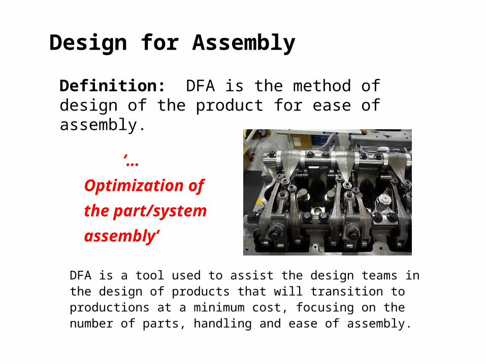
Design for Assembly
Definition: DFA is the method of design of the product for ease of assembly.
‘…Optimization
of the part/system
assembly’
DFA is a tool used to assist the design teams in the design of products that will transition to productions at a minimum cost, focusing on the number of parts, handling and ease of assembly.
Design for Manufacturing
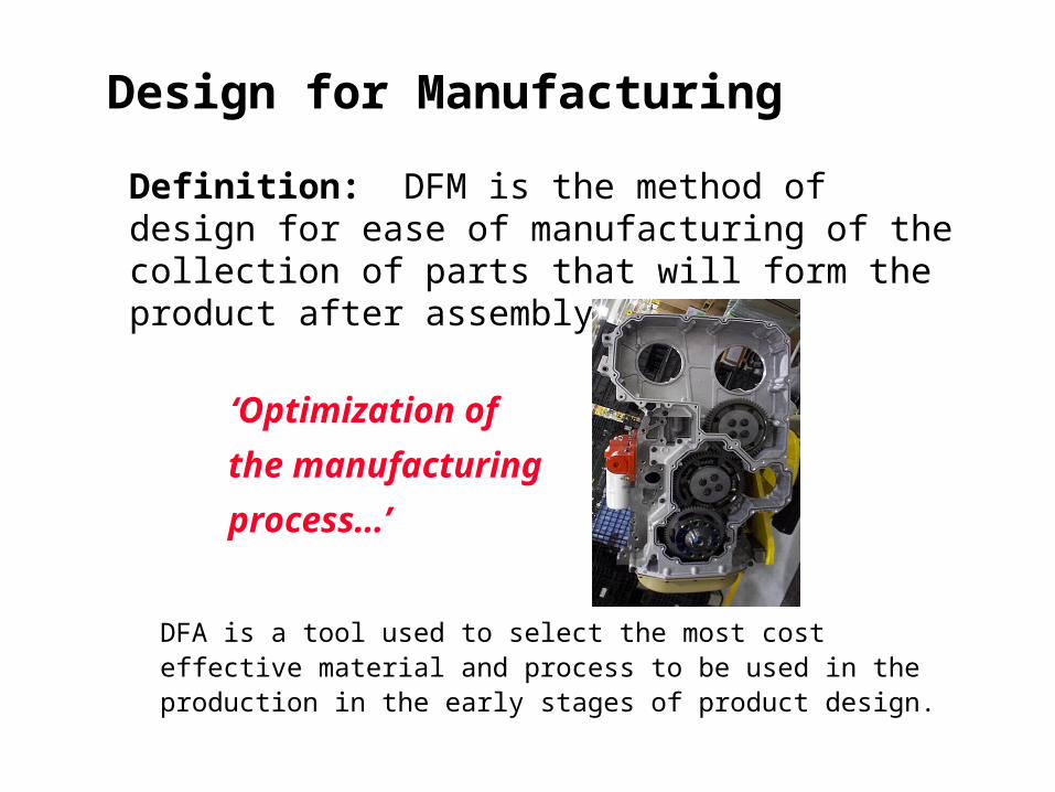
Definition: DFM is the method of design for ease of manufacturing of the collection of parts that will form the product after assembly.
‘Optimization of the
manufacturing
process…’
DFA is a tool used to select the most cost effective material and process to be used in the production in the early stages of product design.
Differences
Design for Assembly (DFA) concerned only with reducing product assembly cost
– minimizes number of assembly operations– individual parts tend to be more complex in design
Design for Manufacturing (DFM) concerned with reducing overall part production cost
– minimizes complexity of manufacturing operations– uses common datum features and primary axes
Similarities
Both DFM and DFA seek to reduce material, overhead, and labor cost.
They both shorten the product development cycle time.
Both DFM and DFA seek to utilize standards to reduce cost
Terminology
Design for Manufacturing (DFM) and Design for Assembly (DFA) are now commonly referred to as a single methodology, Design for Manufacturing and Assembly (DFMA) .

Design
70 - 80%
Manufacturing
20 - 30%
What Internal Organization has the most Influence over Price, Quality, & Cycle Time?
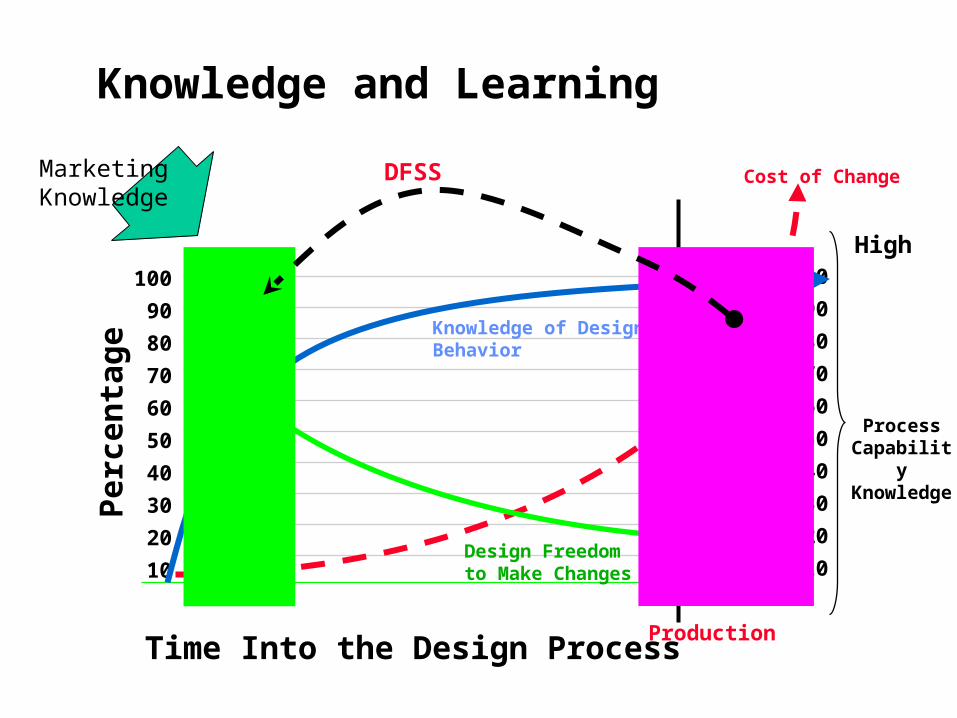
Time Into the Design Process
Per
cen
tag
e
100
90
80
70
60
50
40
30
20
10
100
90
80
70
60
50
40
30
20
10
High
Low
Cost of Change
Design Freedom to Make Changes
Knowledge of Design Behavior
Production
Process Capability Knowledge
DFSSMarketing Knowledge
Knowledge and Learning
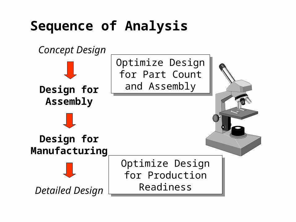
Concept Design
Design for Assembly
Design for Manufacturing
Detailed Design
Optimize Design for Part Count and
Assembly
Optimize Design for Part Count and
Assembly
Optimize Design for Production Readiness
Optimize Design for Production Readiness
Sequence of Analysis
Design for Assembly
DFA is a process that REQUIRES involvement of Assembly Engineers
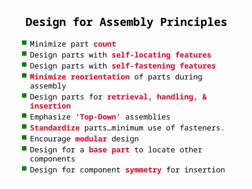
Design for Assembly Principles
Minimize part count Design parts with self-locating features Design parts with self-fastening features Minimize reorientation of parts during assembly Design parts for retrieval, handling, & insertion Emphasize ‘Top-Down’ assemblies Standardize parts…minimum use of fasteners. Encourage modular design Design for a base part to locate other components Design for component symmetry for insertion
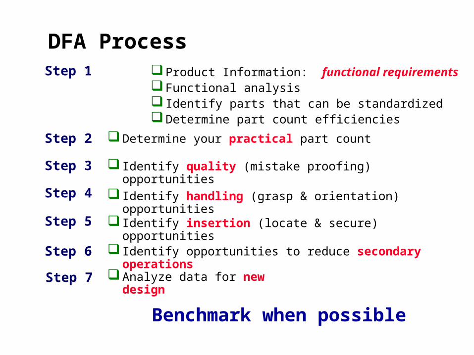
DFA Process Product Information: functional requirements Functional analysis Identify parts that can be standardized Determine part count efficiencies
Step 2
Step 1
Analyze data for new design
Step 3
Identify handling (grasp & orientation) opportunitiesStep 4
Identify insertion (locate & secure) opportunitiesStep 5
Step 6 Identify opportunities to reduce secondary operations
Identify quality (mistake proofing) opportunities
Benchmark when possible
Determine your practical part count
Step 7
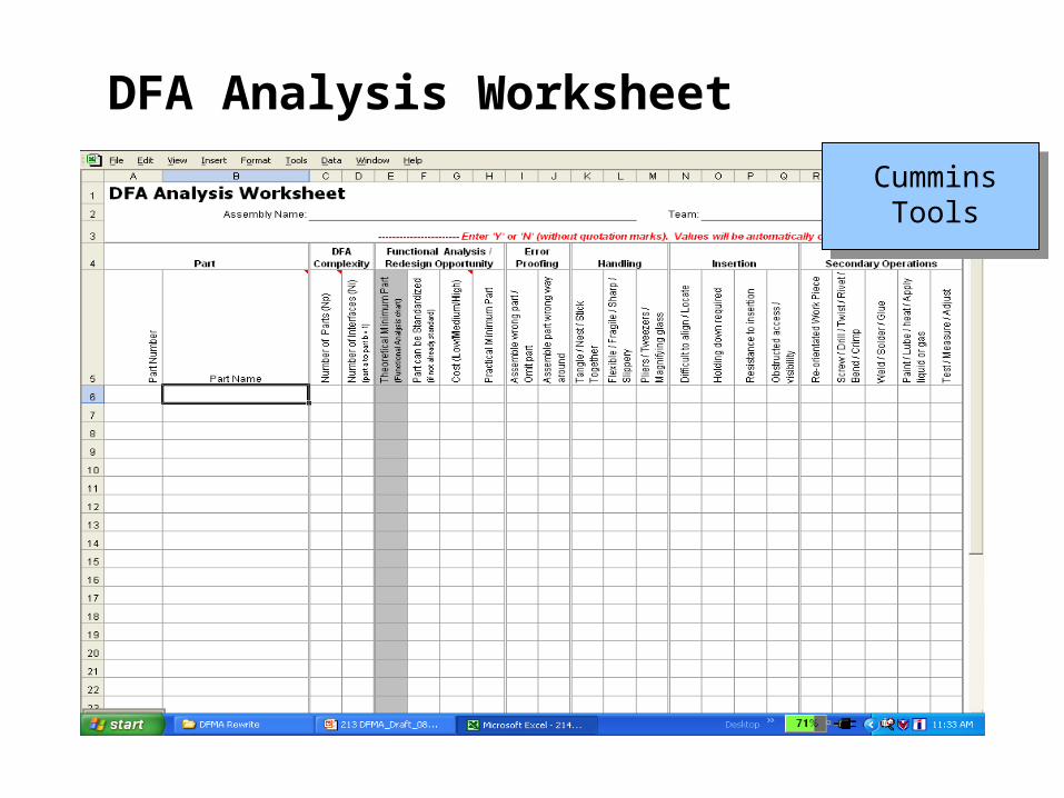
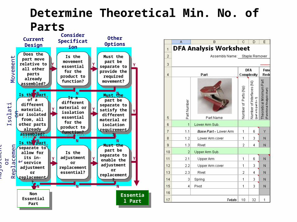
DFA Analysis Worksheet
Cummins Tools
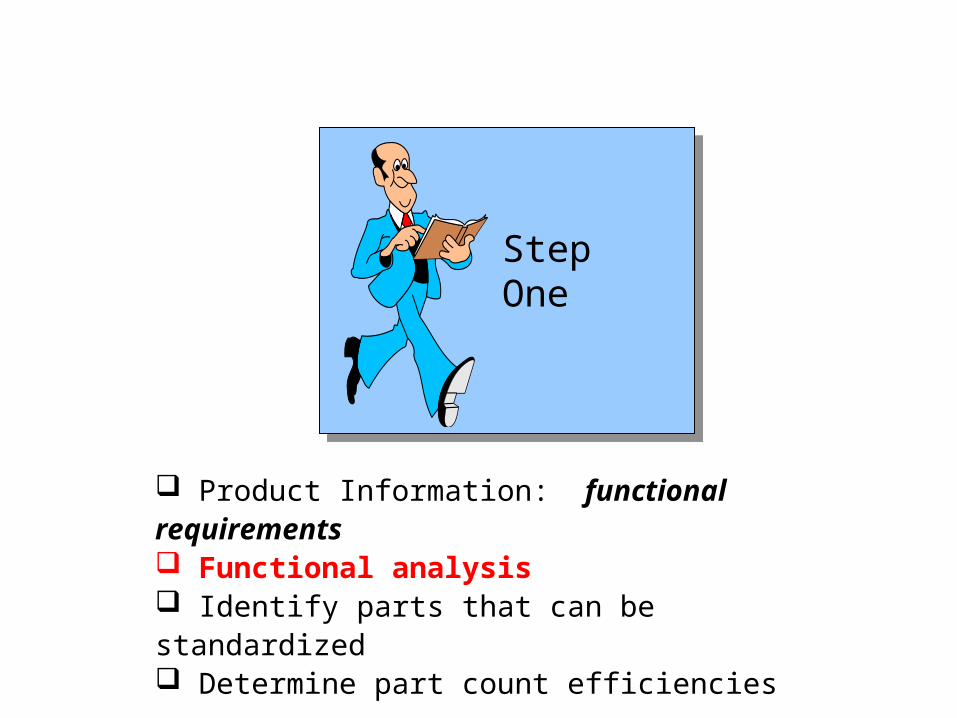
Product Information: functional requirements Functional analysis Identify parts that can be standardized Determine part count efficiencies
Step One

Considerations/Assumptions
The first part is essential (base part)
Non-essential parts:– Fasteners– Spacers, washers, O-rings– Connectors, leads
Do not include liquids as parts (e.g.. glue, gasket sealant, lube)
Step One
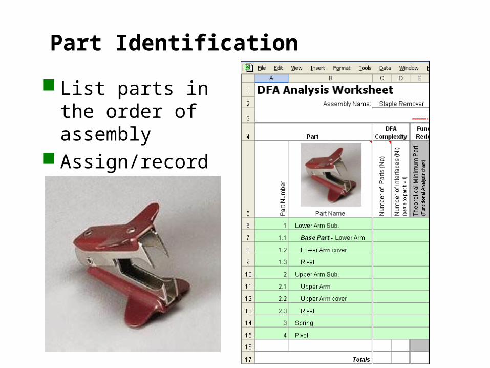
Part Identification
List parts in the order of assembly
Assign/record part number
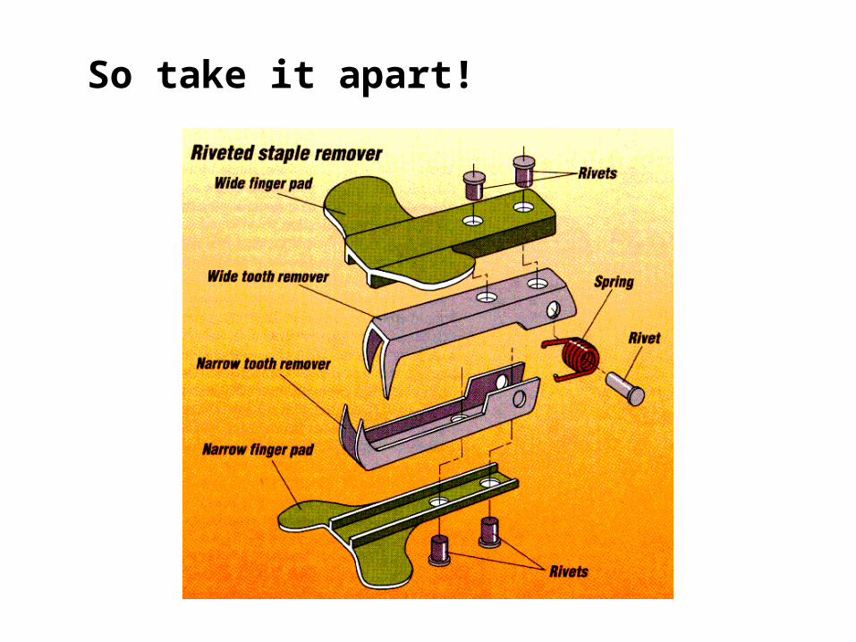
So take it apart!
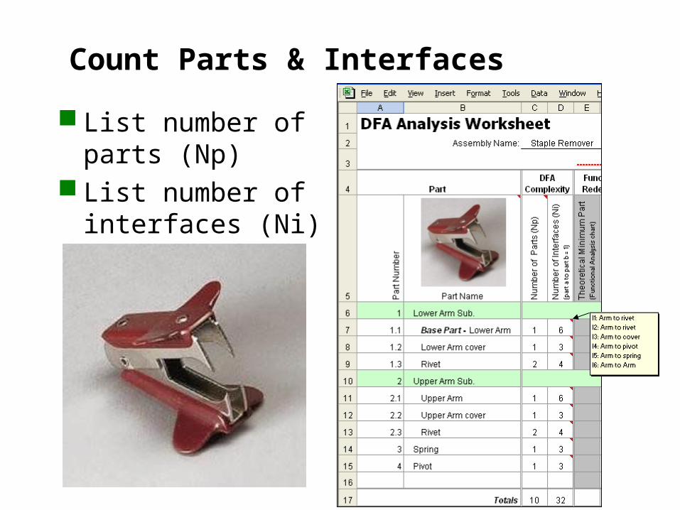
Count Parts & Interfaces
List number of parts (Np)
List number of interfaces (Ni)
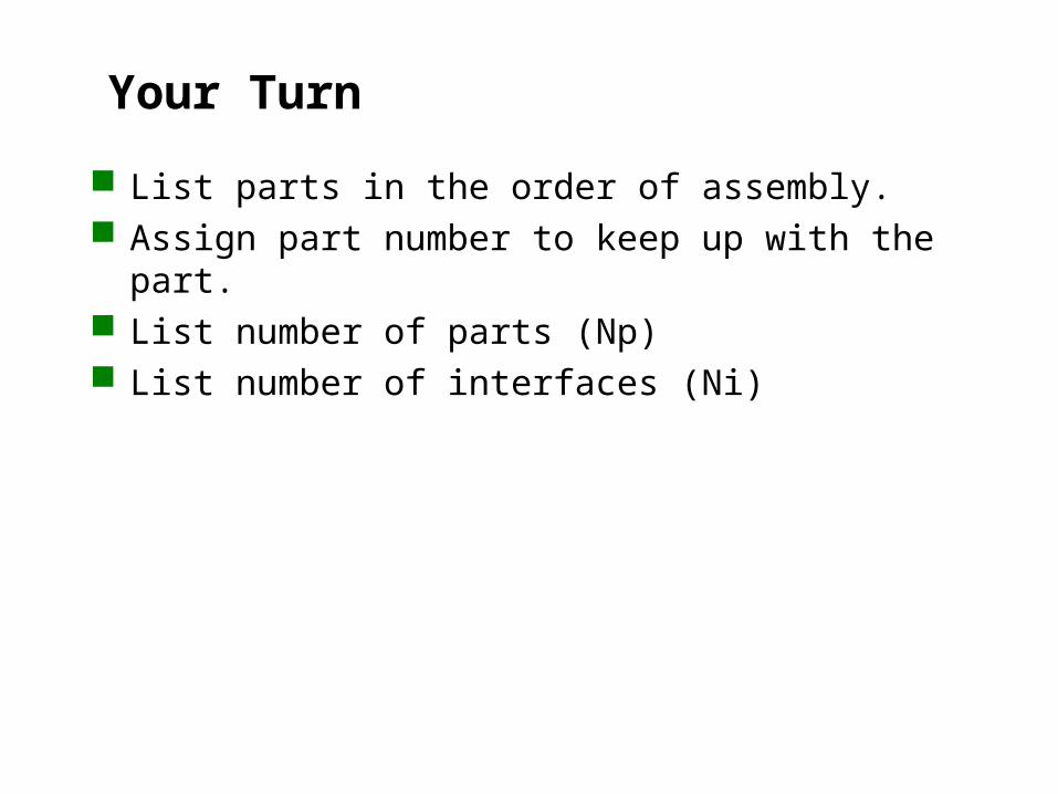
Your Turn
List parts in the order of assembly. Assign part number to keep up with the part. List number of parts (Np) List number of interfaces (Ni)
Current Design
Consider Specification
Other Options
Does the part move relative
to all other parts already assembled?
Does the part move relative
to all other parts already assembled?
Is the part of a different material, or
isolated from, all other parts
already assembled?
Is the part of a different material, or
isolated from, all other parts
already assembled?
Is the part separate to allow for its in-service
adjustment or replacement?
Is the part separate to allow for its in-service
adjustment or replacement?
Is the movement
essential for the product to function?
Is the movement
essential for the product to function?
Is a different material or isolation
essential for the product to function?
Is a different material or isolation
essential for the product to function?
Is the adjustment or replacement essential?
Is the adjustment or replacement essential?
Must the part be separate
to provide the required
movement?
Must the part be separate
to provide the required
movement?
Must the part be separate
to satisfy the different
material or isolation
requirement?
Must the part be separate
to satisfy the different
material or isolation
requirement?
Must the part be separate
to enable the adjustment or replacement?
Must the part be separate
to enable the adjustment or replacement?
Y
Y
Y Y
Y
Y
Essential Part
Essential Part
N N N
N N N
Y
Y
Y
N N N
Non Essential
Part
Non Essential
Part
Determine Theoretical Min. No. of Parts
Mov
eme
ntIs
ola
tion
Adj
ust
men
t o
r R
epla
cem
ent
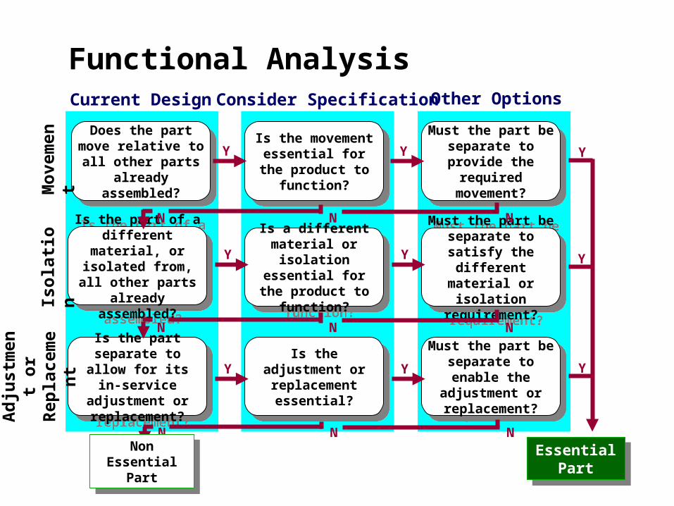
Current Design Consider Specification Other Options
Does the part move relative to all other
parts already assembled?
Does the part move relative to all other
parts already assembled?
Is the part of a different material, or
isolated from, all other parts already
assembled?
Is the part of a different material, or
isolated from, all other parts already
assembled?
Is the part separate to allow for its in-
service adjustment or replacement?
Is the part separate to allow for its in-
service adjustment or replacement?
Is the movement essential for the
product to function?
Is the movement essential for the
product to function?
Is a different material or isolation
essential for the product to function?
Is a different material or isolation
essential for the product to function?
Is the adjustment or replacement essential?
Is the adjustment or replacement essential?
Must the part be separate to provide
the required movement?
Must the part be separate to provide
the required movement?
Must the part be separate to satisfy
the different material or isolation
requirement?
Must the part be separate to satisfy
the different material or isolation
requirement?
Must the part be separate to enable the adjustment or
replacement?
Must the part be separate to enable the adjustment or
replacement?
Y
Y
Y Y
Y
Y
Essential Part
Essential Part
N N N
N N N
Y
Y
Y
N N N
Non Essential Part
Non Essential Part
Functional AnalysisM
ove
me
nt
Iso
lati
on
Ad
just
men
t o
r R
epla
cem
en
t
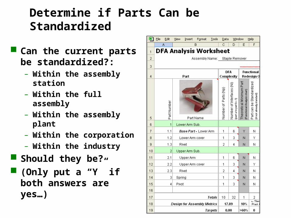
Determine if Parts Can be Standardized
Can the current parts be standardized?:– Within the assembly
station– Within the full assembly– Within the assembly plant– Within the corporation– Within the industry
Should they be? (Only put a “Y” if both
answers are yes…)
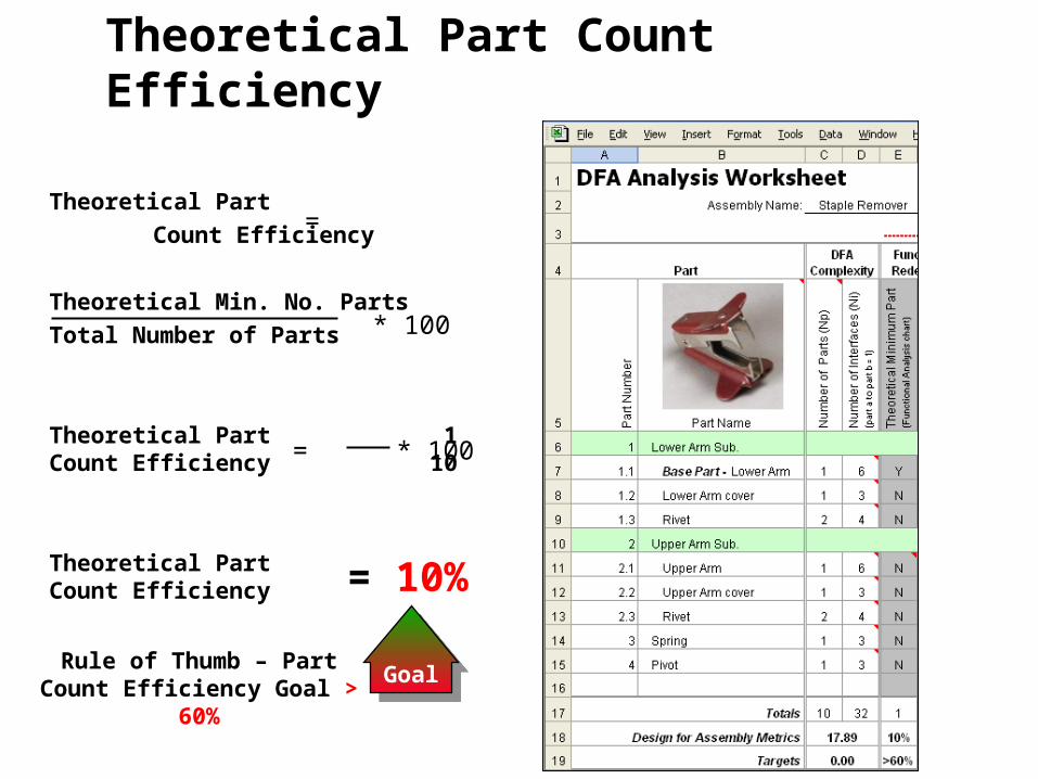
Theoretical Part Count Efficiency
Theoretical Part
Count Efficiency
Theoretical Min. No. Parts
Total Number of Parts
Theoretical Part 1Count Efficiency 10
Theoretical Part Count Efficiency
=
= * 100
= 10%
* 100
GoalGoalRule of Thumb – Part Count
Efficiency Goal > 60%
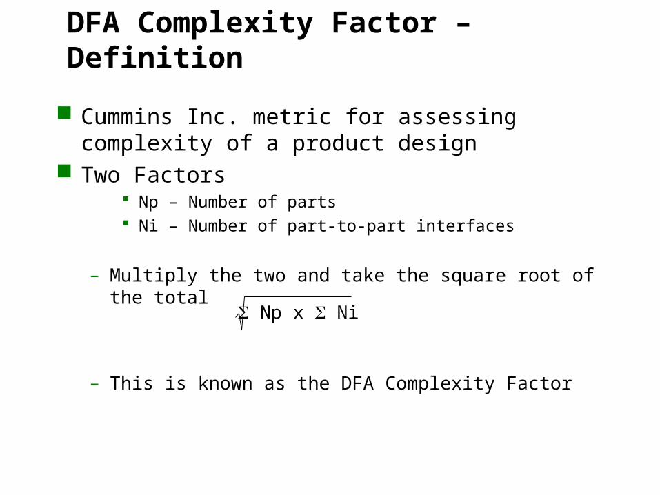
DFA Complexity Factor – Definition
Cummins Inc. metric for assessing complexity of a product design
Two Factors Np – Number of parts Ni – Number of part-to-part interfaces
– Multiply the two and take the square root of the total
– This is known as the DFA Complexity Factor
Np x Ni
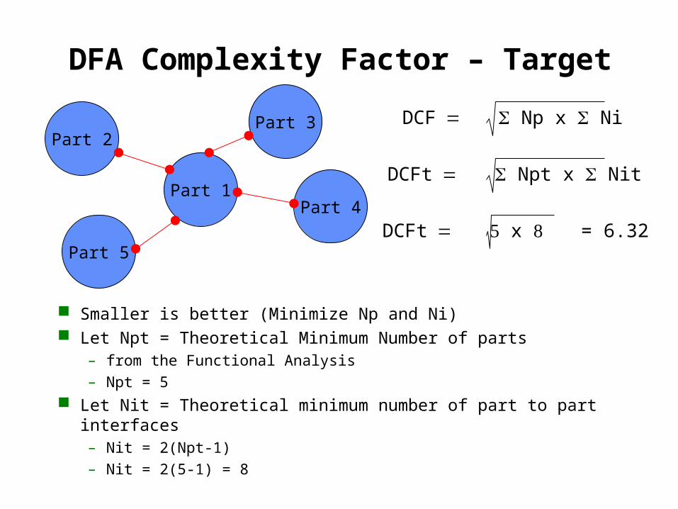
DFA Complexity Factor – Target
Smaller is better (Minimize Np and Ni) Let Npt = Theoretical Minimum Number of parts
– from the Functional Analysis
– Npt = 5
Let Nit = Theoretical minimum number of part to part interfaces– Nit = 2(Npt-1)
– Nit = 2(5-1) = 8
Part 2Part 3
Part 4
Part 5
Part 1
DCF Np x Ni
DCFt Npt x Nit
DCFt x = 6.32
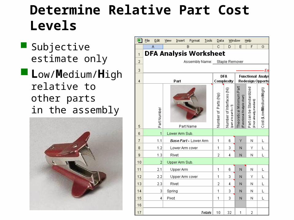
Determine Relative Part Cost Levels
Subjective estimate only
Low/Medium/High relative to other parts in the assembly and/or product line
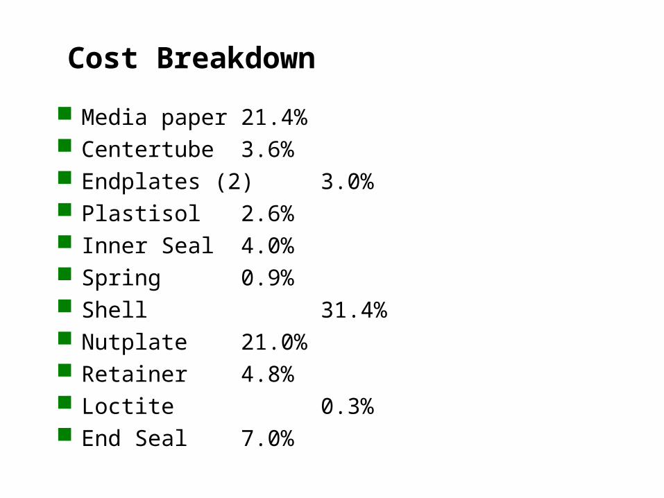
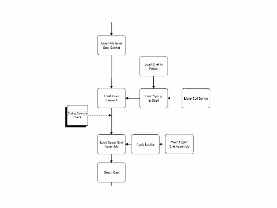
Cost Breakdown
Media paper 21.4% Centertube 3.6% Endplates (2) 3.0% Plastisol 2.6% Inner Seal 4.0% Spring 0.9% Shell 31.4% Nutplate 21.0% Retainer 4.8% Loctite 0.3% End Seal 7.0%
Step Two
Determine Practical Minimum Part Count
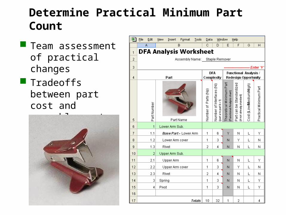
Determine Practical Minimum Part Count
Team assessment of practical changes
Tradeoffs between part cost and assembly cost
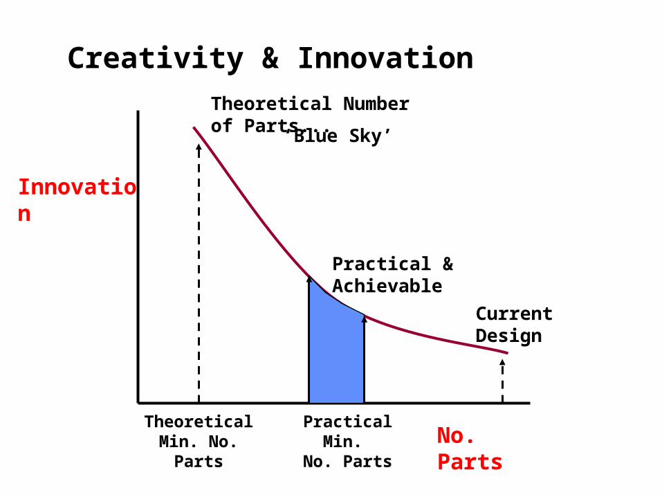
Innovation
No. Parts
Current Design
Practical Min. No. Parts
Practical & Achievable
Theoretical Number of Parts...
Theoretical Min. No. Parts
‘Blue Sky’
Creativity & Innovation
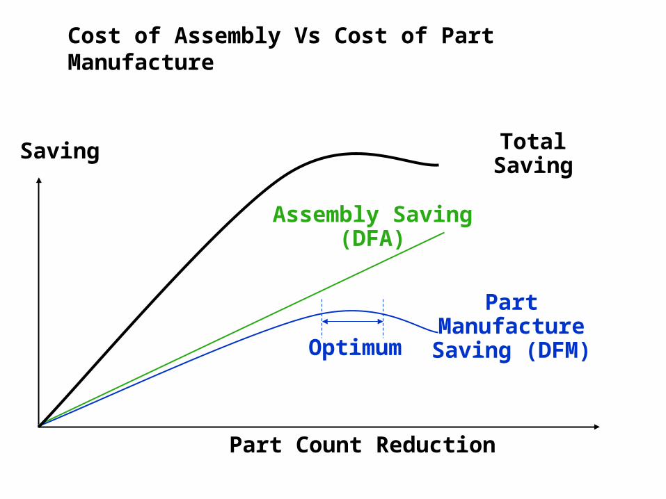
Part Count Reduction
Assembly Saving(DFA)
Part Manufacture Saving (DFM)
Saving
Optimum
Total Saving
Cost of Assembly Vs Cost of Part Manufacture
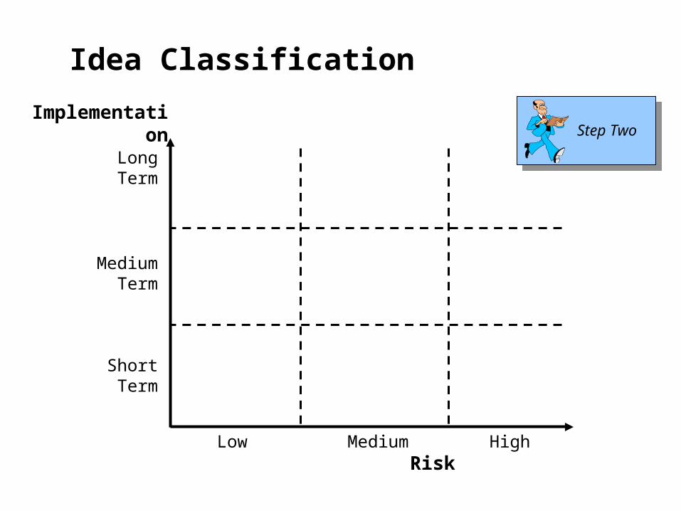
Implementation
RiskHighMediumLow
ShortTerm
MediumTerm
LongTerm
Step Two
Idea Classification

Don’t constrain yourself to incremental improvement unless you have to!
This style doesn’t tear paper like the claw style and is much cheaper to produce!
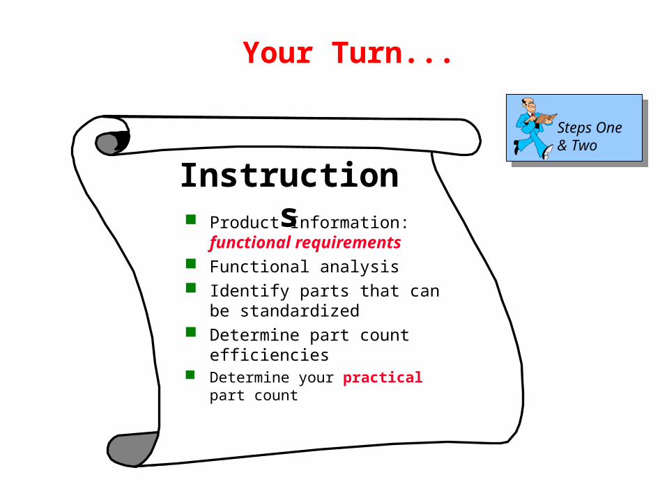
Steps One & Two
Product Information: functional requirements
Functional analysis Identify parts that can be
standardized Determine part count
efficiencies Determine your practical part count
Instructions
Your Turn...
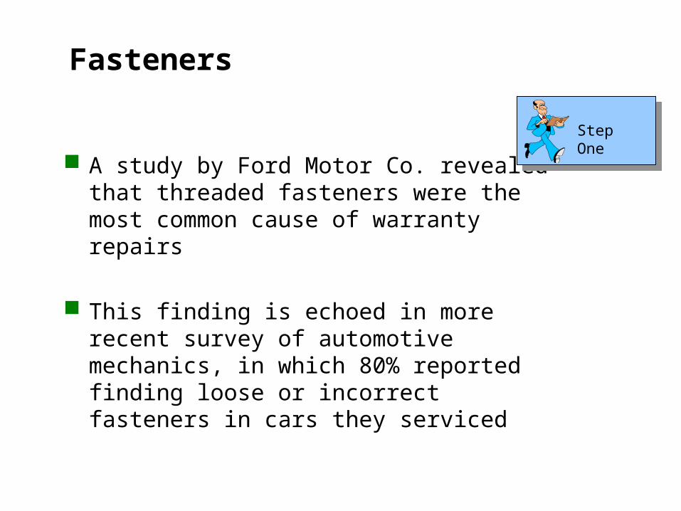
Fasteners
A study by Ford Motor Co. revealed that threaded fasteners were the most common cause of warranty repairs
This finding is echoed in more recent survey of automotive mechanics, in which 80% reported finding loose or incorrect fasteners in cars they serviced
Step One
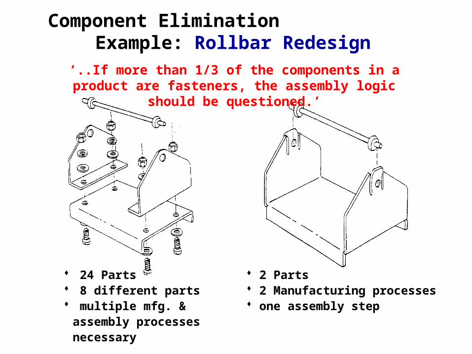
Component EliminationExample: Rollbar Redesign
24 Parts 8 different parts multiple mfg. & assembly
processes necessary
2 Parts 2 Manufacturing processes one assembly step
‘..If more than 1/3 of the components in a product are fasteners, the assembly logic should be questioned.’
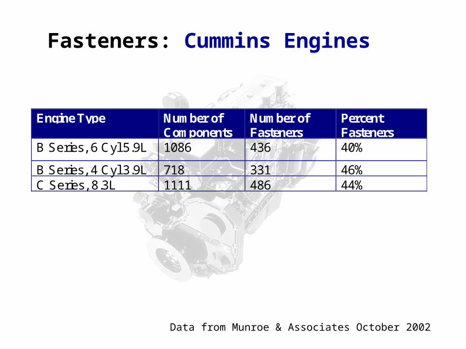
Fasteners: Cummins Engines
Data from Munroe & Associates October 2002
Engine Type Number ofComponents
Number ofFasteners
PercentFasteners
B Series, 6 Cyl 5.9L 1086 436 40%
B Series, 4 Cyl 3.9L 718 331 46%C Series, 8.3L 1111 486 44%
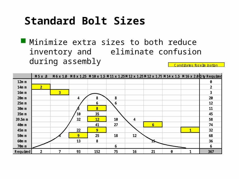
Standard Bolt Sizes
Minimize extra sizes to both reduce inventory and eliminate confusion during assembly
M5 x .8 M6 x 1.0 M8 x 1.25 M10 x 1.5 M11 x 1.25M12 x 1.25 M12 x 1.75 M14 x 1.5 M16 x 2.0 Qty Required12mm 014mm 2 216mm 3 320mm 4 8 8 2025mm 6 6 1230mm 3 8 1135mm 10 35 45
39.5mm 32 12 10 4 5840mm 41 27 6 7445mm 22 9 1 3250mm 4 9 25 18 12 6860mm 13 8 15 3670mm 6 6
Required 2 7 93 152 75 16 21 0 1 367
Candidates for elim ination
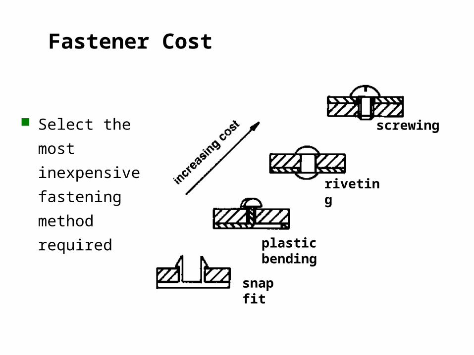
Fastener Cost
Select the
most
inexpensive
fastening
method
required plastic bending
riveting
screwing
snap fit
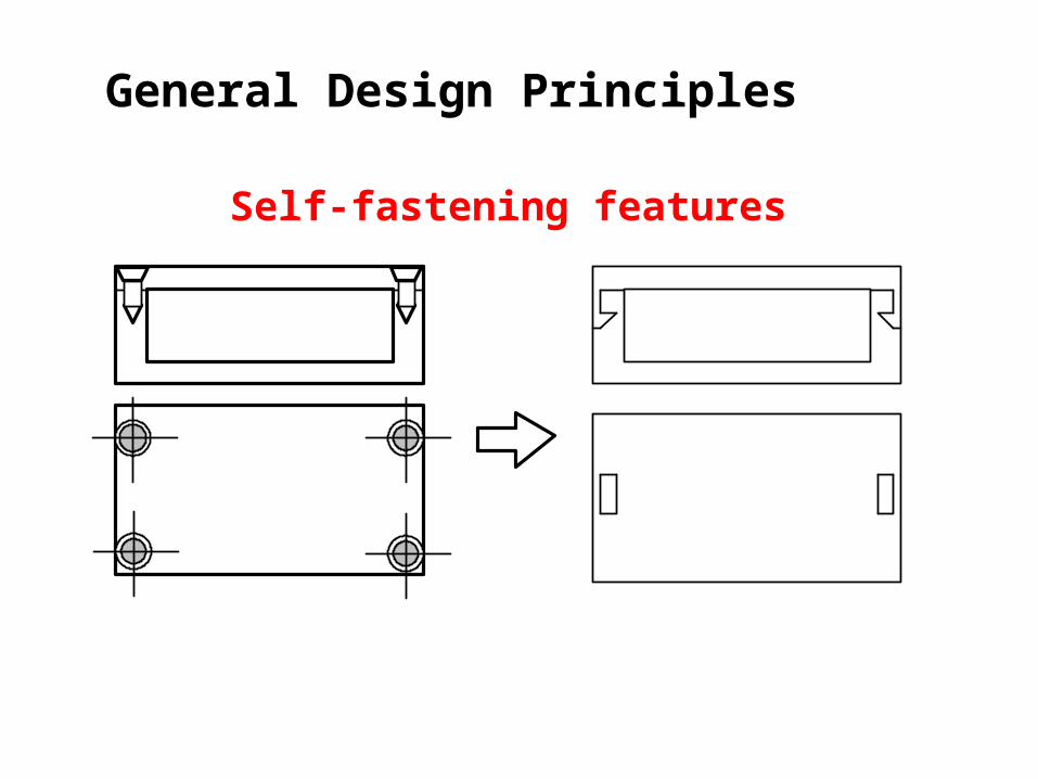
General Design Principles
Self-fastening features
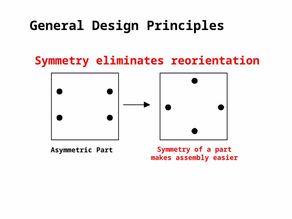
General Design Principles
Asymmetric Part Symmetry of a partmakes assembly easier
Symmetry eliminates reorientation
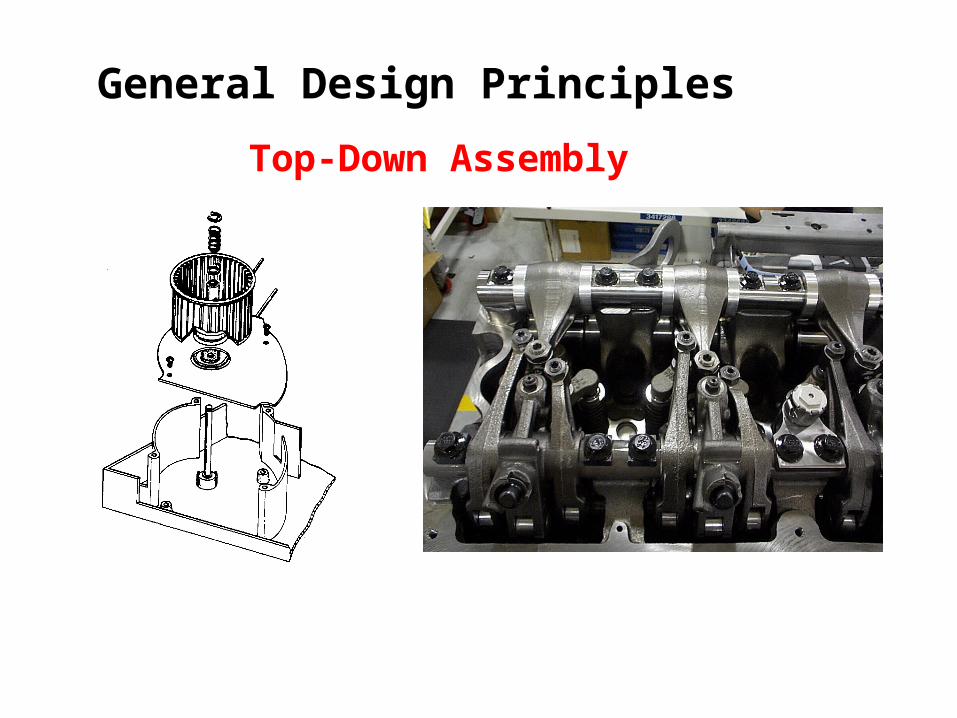
General Design Principles
Top-Down Assembly
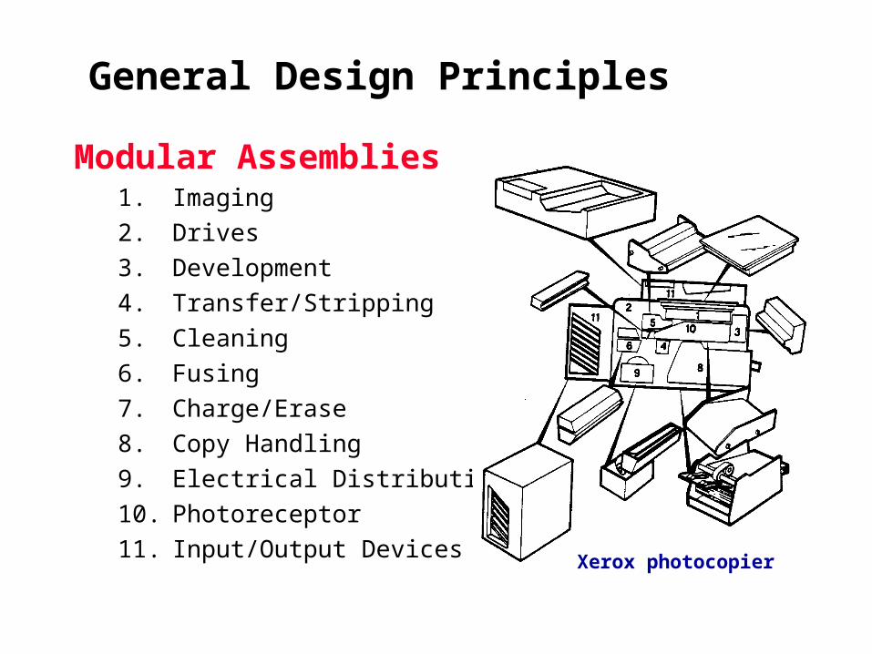
General Design Principles
Modular Assemblies1. Imaging
2. Drives
3. Development
4. Transfer/Stripping
5. Cleaning
6. Fusing
7. Charge/Erase
8. Copy Handling
9. Electrical Distribution
10. Photoreceptor
11. Input/Output DevicesXerox photocopier

Designed Detailed Prototyped Produced Scrapped Tested Re-engineered Purchased Progressed
Received Inspected Rejected Stocked Outdated Written-off Unreliable Recycled late from the supplier!
Eliminated Parts are NEVER…

Step Three
Identify quality (mistake proofing) opportunities
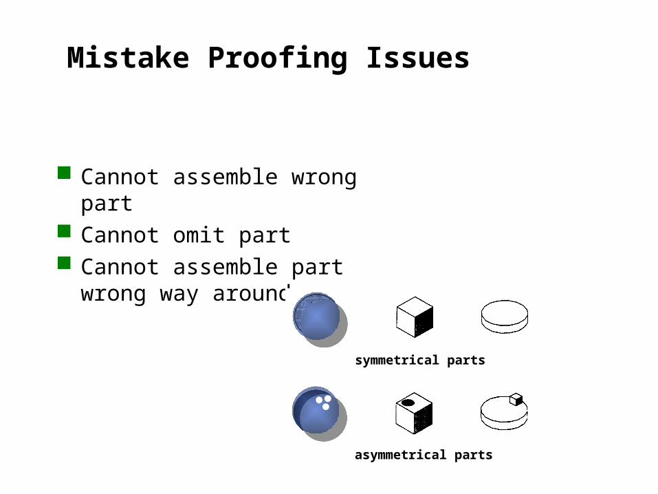
Mistake Proofing Issues
Cannot assemble wrong part Cannot omit part Cannot assemble part wrong
way around.
symmetrical parts
asymmetrical parts
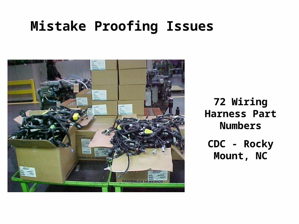
Mistake Proofing Issues
72 Wiring Harness Part Numbers
CDC - Rocky Mount, NC
Step Four
Identify handling (grasp & orientation) opportunities
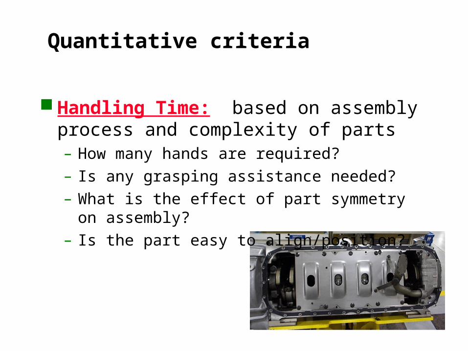
Quantitative criteria
Handling Time: based on assembly process and complexity of parts– How many hands are required?– Is any grasping assistance needed?– What is the effect of part symmetry on assembly?– Is the part easy to align/position?
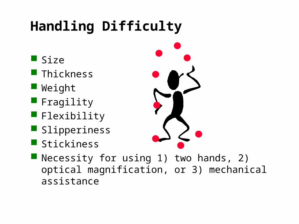
Handling Difficulty
Size Thickness Weight Fragility Flexibility Slipperiness Stickiness Necessity for using 1) two hands, 2) optical
magnification, or 3) mechanical assistance

Handling Difficulty
size slipperiness
sharpness flexibility
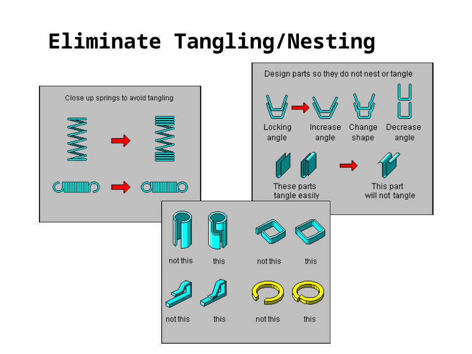
Eliminate Tangling/Nesting
Step Five
Identify insertion (locate & secure) opportunities
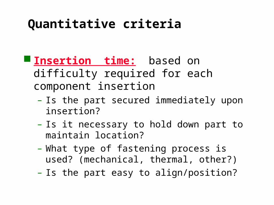
Quantitative criteria
Insertion time: based on difficulty required for each component insertion– Is the part secured immediately upon insertion?– Is it necessary to hold down part to maintain
location?– What type of fastening process is used?
(mechanical, thermal, other?)– Is the part easy to align/position?
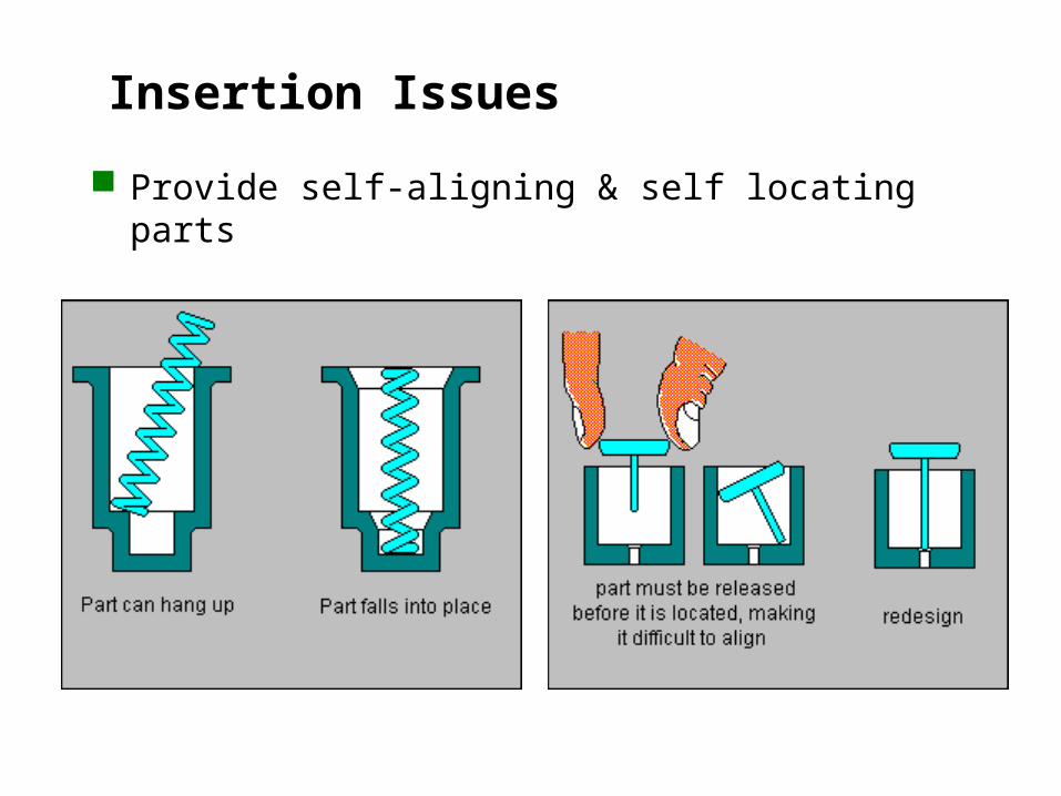
Insertion Issues
Provide self-aligning & self locating parts

Insertion Issues
Ensure parts do not need to be held in position
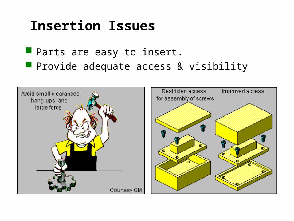
Insertion Issues
Parts are easy to insert. Provide adequate access & visibility
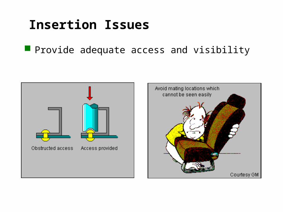
Insertion Issues
Provide adequate access and visibility
Step Six
Identify opportunities to reduce secondary operations

Eliminate Secondary Operations
Re-orientation (assemble in Z axis) Screwing, drilling, twisting, riveting, bending,
crimping.
Rivet
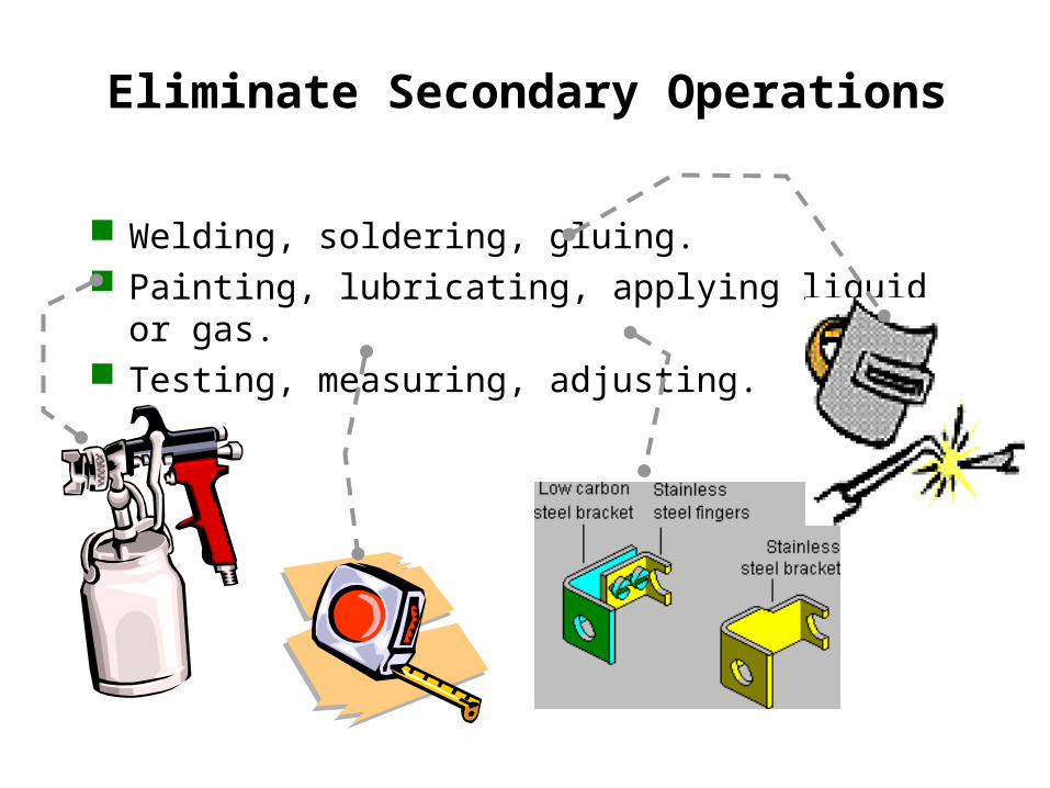
Eliminate Secondary Operations
Welding, soldering, gluing. Painting, lubricating, applying liquid or gas. Testing, measuring, adjusting.
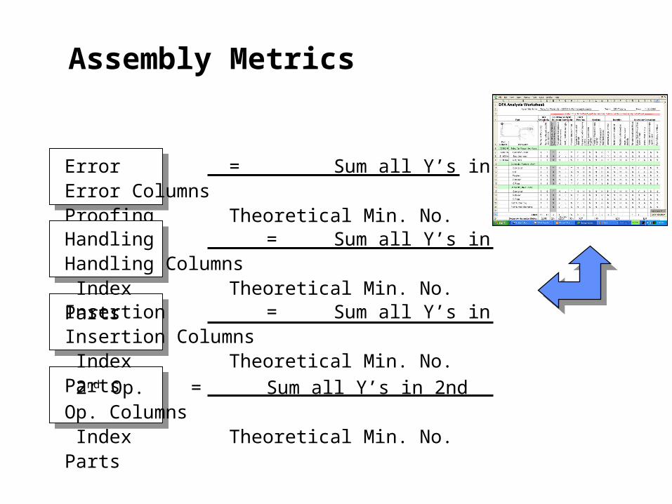
Error = Sum all Y’s in Error Columns Proofing Theoretical Min. No. Parts
Handling = Sum all Y’s in Handling Columns Index Theoretical Min. No. PartsInsertion = Sum all Y’s in Insertion Columns Index Theoretical Min. No. Parts
2nd Op. = Sum all Y’s in 2nd Op. Columns Index Theoretical Min. No. Parts
Assembly Metrics
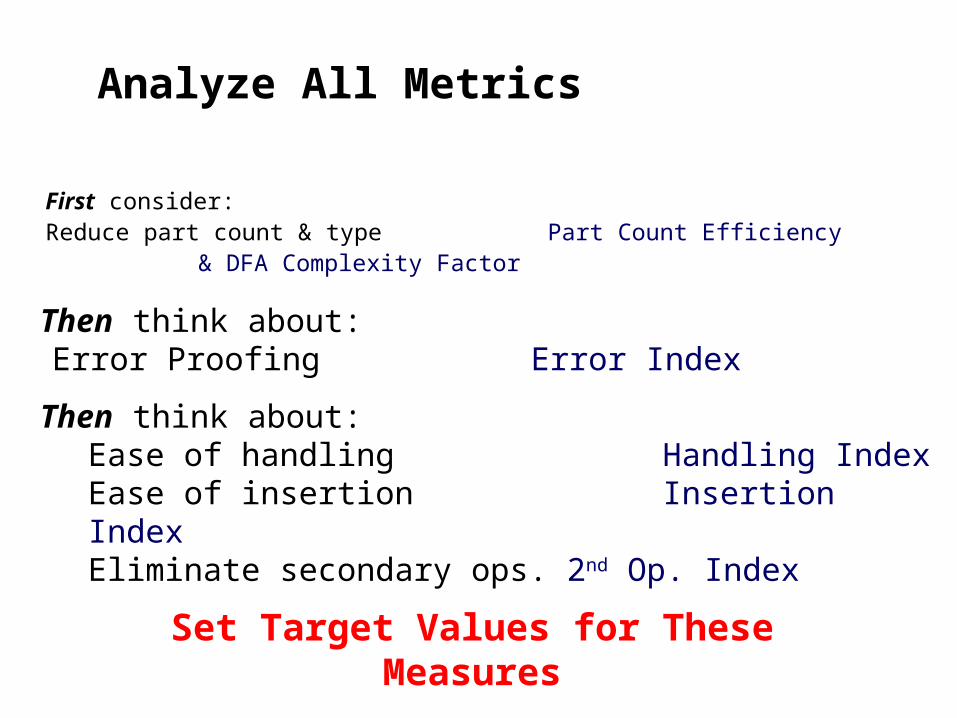
Analyze All Metrics
First consider:Reduce part count & type Part Count Efficiency
& DFA Complexity Factor
Then think about:Error Proofing Error Index
Then think about:Ease of handling Handling IndexEase of insertion Insertion IndexEliminate secondary ops. 2nd Op. Index
Set Target Values for These Measures
Complete the remaining columns & calculate your product’s Assemblability Indices
Instructions
Steps Two - Six
Your Turn...

Step Seven
Analyze data for new design

DFA Process Product Information: functional requirements Functional analysis Identify parts that can be standardized Determine part count efficiencies
Step 2
Step 1
Analyze data for new design
Step 3
Identify handling (grasp & orientation) opportunitiesStep 4
Identify insertion (locate & secure) opportunitiesStep 5
Step 6 Identify opportunities to reduce secondary operations
Identify quality (mistake proofing) opportunities
Benchmark when possible
Determine your practical part count
Step 7
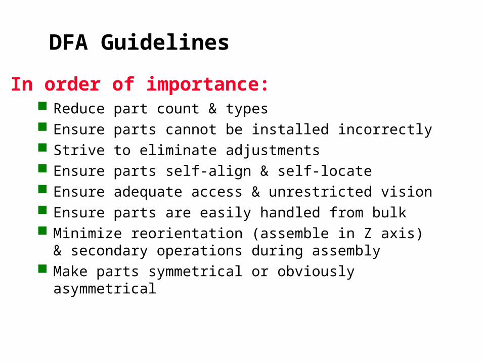
In order of importance:
DFA Guidelines
Reduce part count & types Ensure parts cannot be installed incorrectly Strive to eliminate adjustments Ensure parts self-align & self-locate Ensure adequate access & unrestricted vision Ensure parts are easily handled from bulk Minimize reorientation (assemble in Z axis) &
secondary operations during assembly Make parts symmetrical or obviously asymmetrical
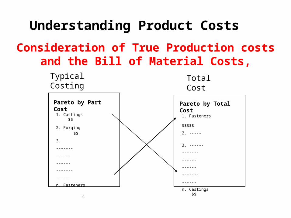
Consideration of True Production costs and the Bill of Material Costs,
Typical Costing Total Cost
Pareto by Part Cost
1. Castings $$
2. Forging $$
3.
-------
------
------
-------
------
n. Fasteners c
Pareto by Total Cost
1. Fasteners $$$$$
2. -----
3. ------
-------
------
------
-------
------
n. Castings $$
Understanding Product Costs
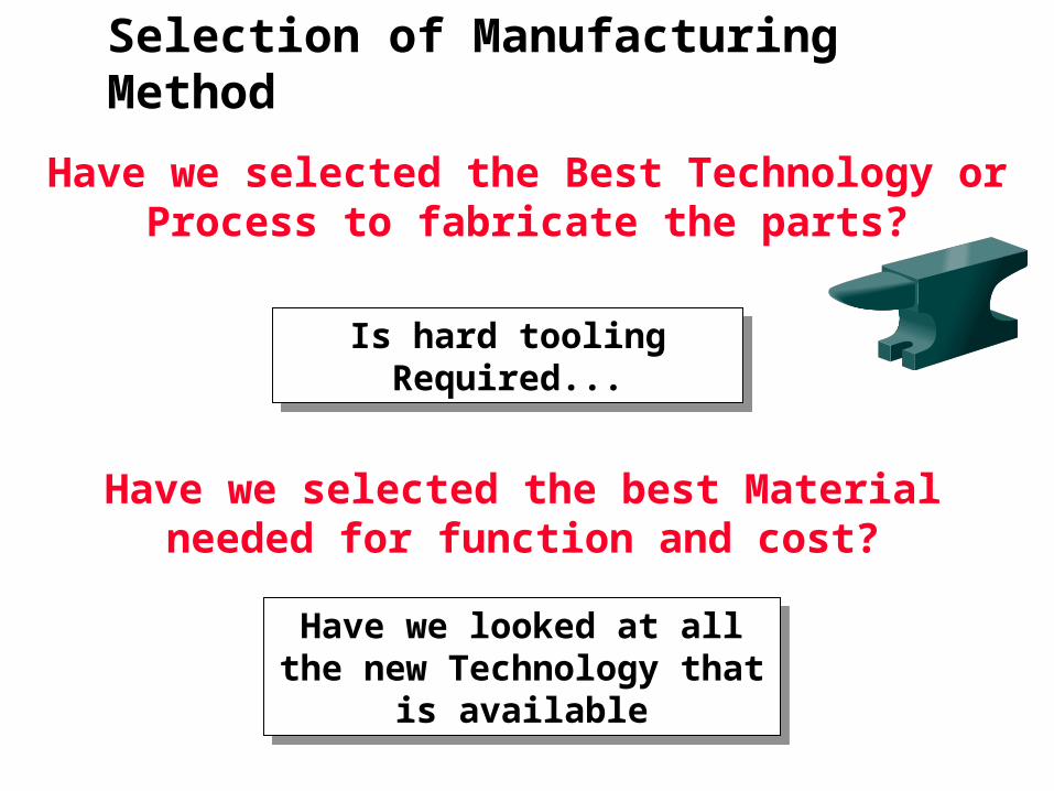
Have we selected the Best Technology or Process to fabricate the parts?
Is hard tooling Required...Is hard tooling Required...
Selection of Manufacturing Method
Have we selected the best Material needed for function and cost?
Have we looked at all the new Technology that is available
Have we looked at all the new Technology that is available
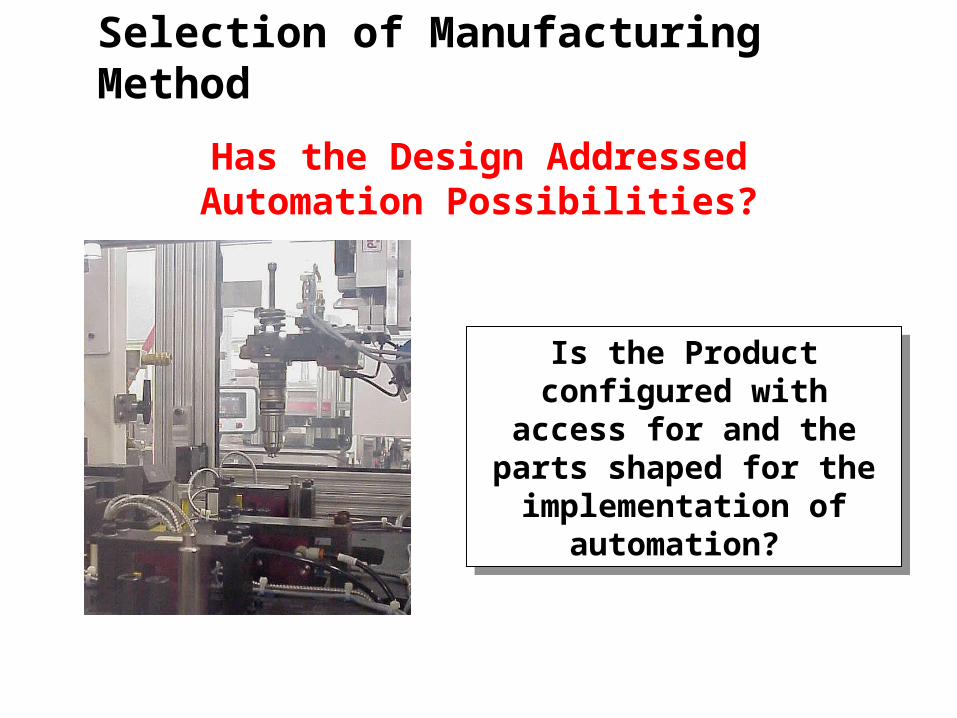
Has the Design Addressed Automation Possibilities?
Is the Product configured with access for and the
parts shaped for the implementation of
automation?
Is the Product configured with access for and the
parts shaped for the implementation of
automation?
Selection of Manufacturing Method
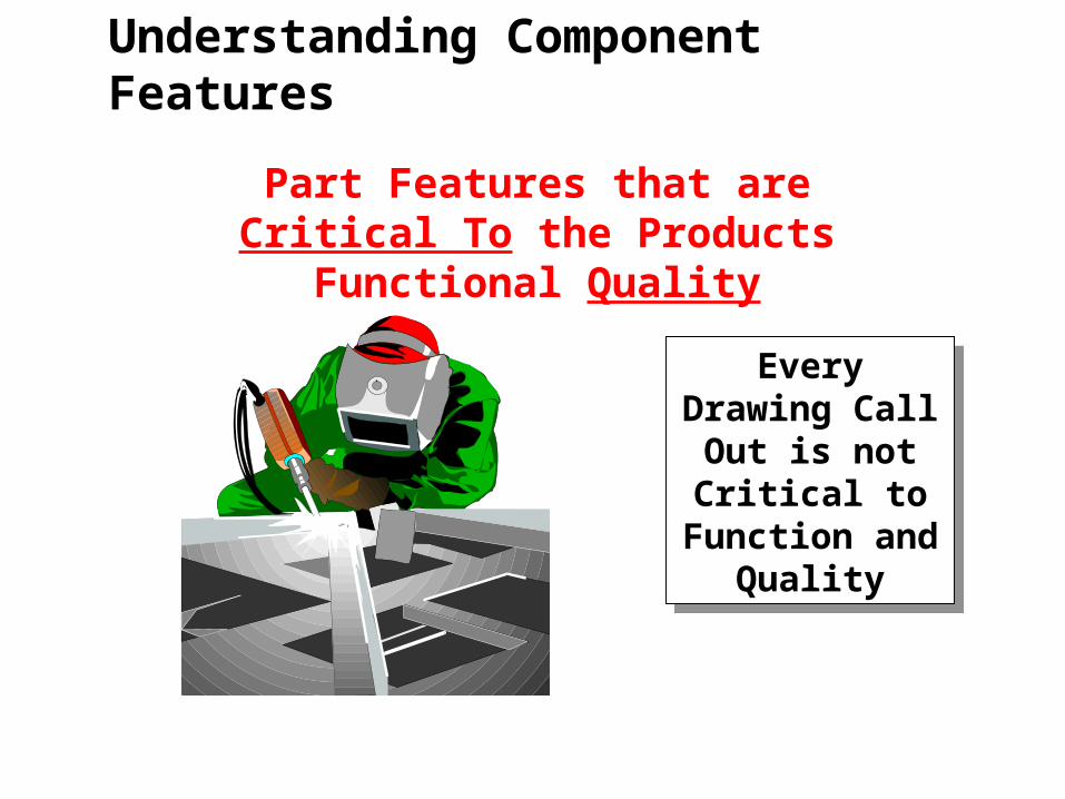
Part Features that are Critical To the Products Functional Quality
Every Drawing Call Out is not
Critical to Function and
Quality
Every Drawing Call Out is not
Critical to Function and
Quality
Understanding Component Features
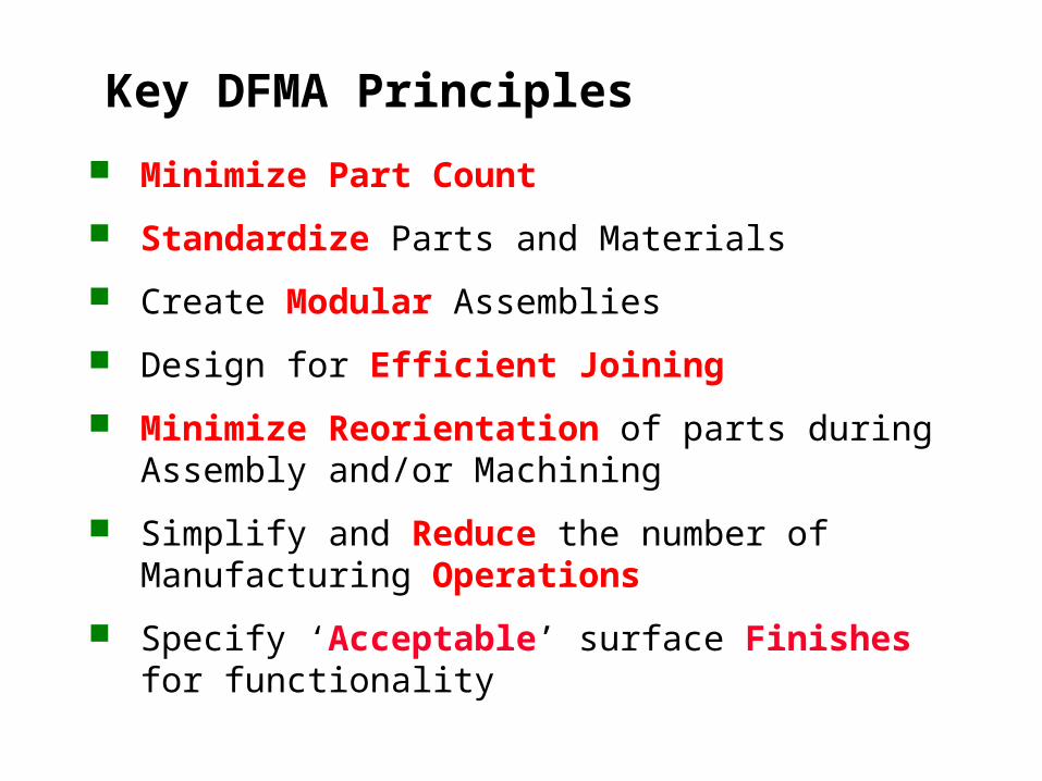
Key DFMA Principles
Minimize Part Count
Standardize Parts and Materials
Create Modular Assemblies
Design for Efficient Joining
Minimize Reorientation of parts during Assembly and/or Machining
Simplify and Reduce the number of Manufacturing Operations
Specify ‘Acceptable’ surface Finishes for functionality
1. Assembly Automation and Product Design
G. Boothroyd, Marcell Dekker, Inc. 1992
2. Product Design for Manufacture and Assembly
G. Boothroyd and P. Dewhurst, Boothroyd Dewhurst, Inc. 1989
Marcell Dekker, Inc. 1994
3. Design and Analysis of Manufacturing Systems
Prof. Rajan Suri University of Wisconsin 1995
4. Product Design for Assembly: The Methodology Applied
G. Lewis and H. Connelly
5. Simultaneous Engineering Study of Phase II Injector Assembly line
Giddings & Lewis 1997
6. Design for Manufacturing Society of Manufacturing Engineers,
(VIDEO)
References


