50
Diagnosing and Solving Plunger Lift Problems David Green, P.Eng. Well Master Corporation

Diagnosing and Solving Plunger Lift Problems
David Green, P.Eng.Well Master Corporation

What’s Wrong With My well?

Problem Areas
Mechanical Factors• Surface Facilities• Tubing Placement• Holes in Tubing• Tubing Tight Spots
Plunger Factors• Worn Plunger• Wrong Plunger• Incorrect
Operating Parameters
• Scale, Paraffin, Sand

What Diagnostic Tools Do We Have?
• Eyes and Ears• Wellhead Controllers• Flow Measurement Devices• SCADA Systems• Acoustic Device • Instrumented Plunger (Pressure,
Temperature, Location)
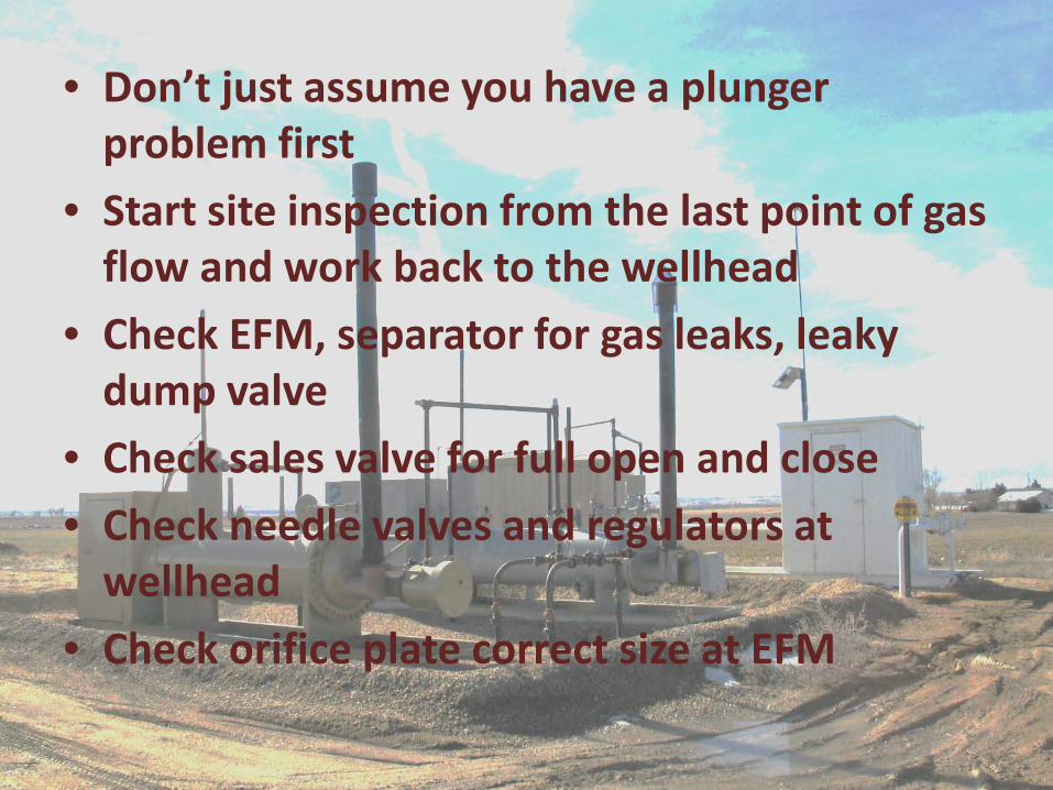
Site Inspection• Don’t just assume you have a plunger problem first
• Start site inspection from the last point of gas flow and work back to the wellhead
• Check EFM, separator for gas leaks, leaky dump valve
• Check sales valve for full open and close• Check needle valves and regulators at
wellhead• Check orifice plate correct size at EFM

Plunger Inspection• Pull plunger to inspect
for damage• Measure solid plunger
diameter with micrometer or use gauge ring
• Inspect pad plungers for pad wear and loss of spring tension – use a gauge ring if available
• Insect brush plungers for wear

What Diagnostic Tools Do We Have?
• Eyes and Ears• Wellhead Controllers• Flow Measurement Devices• SCADA Systems• Acoustic Device • Instrumented Plunger (Pressure,
Temperature, Location)

SCADA • Often times we can see problems with our SCADA systems• Typical things to look for:
– Rising casing pressure trends (loading)– Increasing casing – tubing differential pressures (loading)– Loss of tubing pressure in closed cycle (leaking sales
valve)– Rapid equalization of casing and tubing pressures (hole in
tubing)– Unusual patterns…..usually point to more serious things

Blocked Intake into Tubing
Tbg Pressure Rapid Build
Rapid Tbg Pressure Decline
Casing Pressure at start should have surfaced plunger in 1.89 minutes – instead plunger took 23 minutes to surface
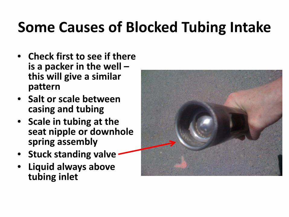
Some Causes of Blocked Tubing Intake
• Check first to see if there is a packer in the well –this will give a similar pattern
• Salt or scale between casing and tubing
• Scale in tubing at the seat nipple or downhole spring assembly
• Stuck standing valve• Liquid always above
tubing inlet

55--1616--6868--12 Gas Production12 Gas ProductionSmall hole Small hole Began to Began to
Cause Cause ProblemProblem
Replaced Replaced Tubing andTubing andGas Flow Gas Flow
Returned to Returned to 2006 Rate2006 Rate
Drop in Production due Drop in Production due to Liquid Loading? to Liquid Loading? Shot Fluid Levels to Shot Fluid Levels to Open Sliding Sleeve and Open Sliding Sleeve and Commingle Two Zones Commingle Two Zones
Found Hole in Tubing Found Hole in Tubing With Fluid Level Shot With Fluid Level Shot
Dramatic Drop in Rate Dramatic Drop in Rate
820 Mscfd 250 Mscfd 820 Mscfd 250 Mscfd
Turner Critical Turner Critical 320 MscfD320 MscfD

Holes in Tubing and Corrosion in Flowing Gas Wells are a Common Problem
• Tubing holes often misdiagnosed or over-looked.• Production rate drops and looks like liquid loading
as gas rate falls off• Casing-tubing pressure gradually equalizes during
close cycle (easier to see if SCADA data is available)• Problems occur gradually as hole size increases• Plunger begins to slow-trip or miss trips• Often the plunger is changed when wear is
suspected, but results don’t change
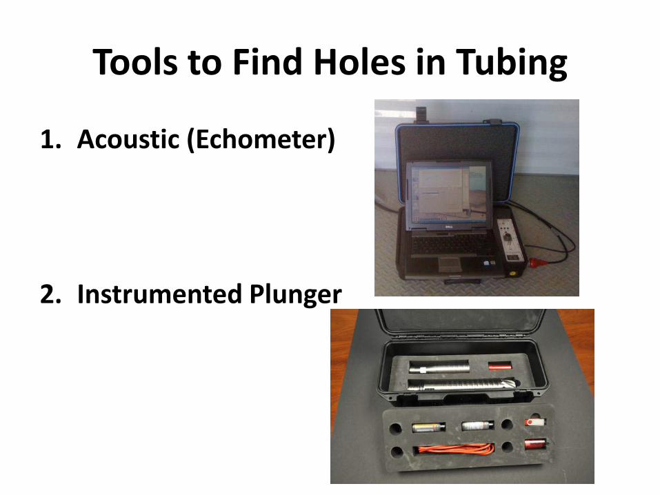
Tools to Find Holes in Tubing
1. Acoustic (Echometer)
2. Instrumented Plunger

CanCan’’t be a Hole ~ Tubing is Newt be a Hole ~ Tubing is NewHole @ Hole @ Depth 4325 Ft from SurfaceDepth 4325 Ft from Surface
Outside PipeOutside PipeInside PipeInside Pipe

1. Well was Liquid Loaded 2. Fluid Level Shots Showed Tubing was OK3. Installed plunger and couldn’t surface the plunger4. Took more tbg shot’s. 5. Then the upkick showed up in the tbg as the well
was shut in for a while. 6. Original shot’s did not expose the hole in the tbg
as the well was loaded up with Gassy Liquid Above Hole
Tubing Hole -- Sand Blast Gas Flow From Upper Set of Perforations
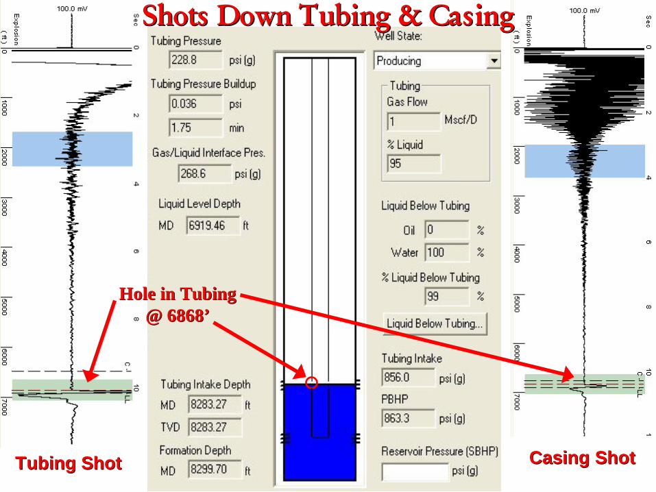
Shots Down Tubing & CasingShots Down Tubing & Casing
Hole in TubingHole in Tubing@ 6868@ 6868’’
Tubing ShotTubing Shot Casing ShotCasing Shot
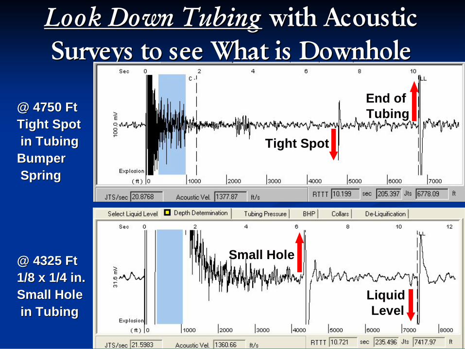
Look Down TubingLook Down Tubing with Acoustic with Acoustic Surveys to see What is DownholeSurveys to see What is Downhole
@ 4750 Ft@ 4750 FtTight SpotTight Spotin Tubingin TubingBumperBumperSpringSpring
@ 4325 Ft@ 4325 Ft1/8 x 1/4 in.1/8 x 1/4 in.Small HoleSmall Holein Tubingin Tubing
Tight SpotTight Spot
Small HoleSmall Hole
Liquid Liquid LevelLevel
End of End of TubingTubing

Plunger Fall Plunger Rise ->
Plunger hits liquid
Using an Instrumented Plunger to Determine Hole in Tubing
Plunger on Bottom Plunger at Surface

1. Select fall portion and zoom below
Temperature anomaly occurs due to gas entering from casing into tubing above liquid level. Drop in pressure causes cooling which is detected as instrumented plunger passes.
2. Set range to temperature anomaly
3. Find approximate depth to hole at 230 collars or 7245 ft.

Observations of Plunger Rise Characteristics with a Hole in Tubing
Zoom in on Rise Portion of Data
Plunger rises slowly and loses velocity until it stalls out. Rise rate is only 155 ft./min average over the first 39 collars.
Interesting to observe plunger stalls, loses liquid load and rises a few joints, then repeats several times

Look now at the final rise portion of the data
Average velocity over 308 collars is almost 400 ft./min
Plunger has now completely lost the fluid load and can continue to surface

Look now at the very last rise portion of the data….
The plunger travels the last 24 collars at 1317 ft./min as it comes into the lubricator. Would that be confusing? What would your thoughts be while waiting over an hour for this plunger to arrive?

Tubing Hole and Corrosion Conclusions
• DO NOT be surprised if your liquid loaded gas wells have holes in the tubing.
• Holes cause significant drop in gas production. • Large gas production increase is possible due to repairing
the hole in the tubing and returning the gas well to unloaded flowing state.
• Shooting fluid levels to detect hole in tubing is a fairly simple process and can provide good accuracy of location
• An instrumented plunger can quickly show the presence of a hole but is less accurate in determining location, especially if only the pressure and temperature trends are available
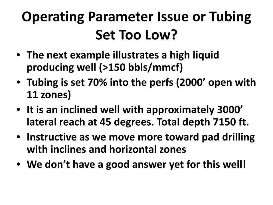
Operating Parameter Issue or Tubing Set Too Low?
• The next example illustrates a high liquid producing well (>150 bbls/mmcf)
• Tubing is set 70% into the perfs (2000’ open with 11 zones)
• It is an inclined well with approximately 3000’ lateral reach at 45 degrees. Total depth 7150 ft.
• Instructive as we move more toward pad drilling with inclines and horizontal zones
• We don’t have a good answer yet for this well!

Casing P Tubing P
Line P
Net Gas
“Hand” pattern of progressive loading over 4-5 cycles until plunger fails to surface. Mandatory shut-in, then gas injection into annulus restarts pattern.
Off time and afterflow time extended to 100 minutes and approx. 30 minutes respectively (low flow cutoff at 350 mcf/d) showed temporary improvement.

Instrumented Plunger on the same well….
Mandatory shut-in
Plunger fails to surface
Gas injection
Fast trip Increased loading Fail and repeat

First cycle – mandatory shut-in fails to build sufficient casing pressure to lift the load.
Plunger only moves up 105 collars at avg speed of 294 ft./min then stalls out and drops back to bottom

Gas injection on but little change in bottom hole pressure. Blockage in annulus at or above upper perfs???
Plunger makes a “normal” trip at a fast rate of 1195 ft./min. Lots of liquid to surface.
Try again… this time with gas injection into the annulus at surface…..

The next plunger fall shows no liquid in the tubing, although there could be “mist”.
No signature pressure gradient kick that would indicate liquid
Plunger falls at an average rate consistent with gas only at this pressure – 300 ft./min

Fast arrival on the next trip due to minimal or perhaps no liquid load…
Plunger makes a very fast trip at a rate of 2455 ft./min. Little or no liquid to surface.

Liquid loading starts to occur….
Pressure gradient kick at 220 collars indicates 220 ft. of liquid (TD 7150 ft. minus 6930 ft.)

Rise velocity declines as loading increases…
Plunger makes a still fast but slower trip at a rate of 1552 ft./min. Some liquid to surface.

The last fall of this “hand” encounters high liquid levels…
Plunger hits liquid at 5260 ft. indicating 1790 ft. of liquid (about 7 bbls of water)
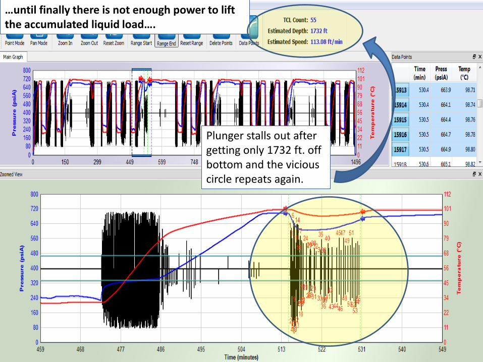
…until finally there is not enough power to lift the accumulated liquid load….
Plunger stalls out after getting only 1732 ft. off bottom and the vicious circle repeats again.
So what’s the problem?• Lack of a casing pressure break with strong tubing
pressure drop indicates blocked gas flow into tubing• Blockage from salt, scale or ????• Likely that tubing is simply set too deep and high liquid
production means the casing gas rarely u-tubes into the tubing
• Gas injection may make the problem worse by pushing liquid back into the formation, resulting in a dry run followed by liquid rushing back into the annulus, causing cyclic pattern of unload-load-fail.
• Poorly understood influence of flow in inclined tubing, especially with the high liquid ratio and high pressures
• Problem is yet to be finally solved!
Vent or Compression Needed?
• Increasing problem to use venting as a technique in normal operation
• Regulations prohibit this as standard operating practice in many jurisdictions and the trend is to increase
• Incidences of venting will need to be documented to satisfy regulatory agencies
• Need to assess whether venting is really necessary or whether operating practice or plunger selection can solve the problem
• Last resort to add compression

What happens when we vent a well?
This is a typical example with low casing pressure over line of around 10-20 psi.
Sales valve is opened, 15 minute delay, then B-valve is opened. One hour shut-in between cycles.

Rise characteristics before vent…
Plunger gets off bottom reasonably well but stalls out after about 8-9 minutes. Avg speed only 252 ft./min

Total average trip time can be deceiving!
If we only look at our total trip time we get a velocity of 370 ft./min. A bit slow but at least an arrival!

Let’s look at the second phase of this trip…
The plunger averages 1150 ft./min after the B-valve is opened. Comes in strong, but with little or no liquid.

What did we learn?• Venting can be inefficient from a plunger velocity
standpoint, even if it makes us feel good because we get an arrival in a difficult well
• Too slow before venting and too fast after venting means the plunger lifting efficiency is compromised at each phase of the lift cycle
• If we must vent in this case, cut the B-valve delay to about 7-8 minutes to avoid stalling
• Also reduce off time 30-50% to cut velocity when going to vent (casing pressure builds very slowly here)
• Result will be additional cycles per day at lower bottom hole pressure and more efficient liquid removal

Venting Not Needed?
• Sometimes we vent just because!• Operating practices can tend to become
“standard” and not changed even if the operating circumstances do change
• This is especially true where SCADA is not used as it is more difficult to spot trends when relying on stand-alone controllers

The Case of “Standard Operating Practice”
Well is set to open at 60 psi over line pressure with a 6 minute delay until the B-valve opens. Same thing all day every day!

Let’s look at the “average” trip….
Plunger arrives in about 6 minutes from over 11,000 ft. Notice how the bottom hole pressure builds between cycles!

How were we doing before the B-valve opened?
Not bad! Certainly running fast but did we need to vent? Plunger speed averaged over 1600 ft./min for 7800 ft.
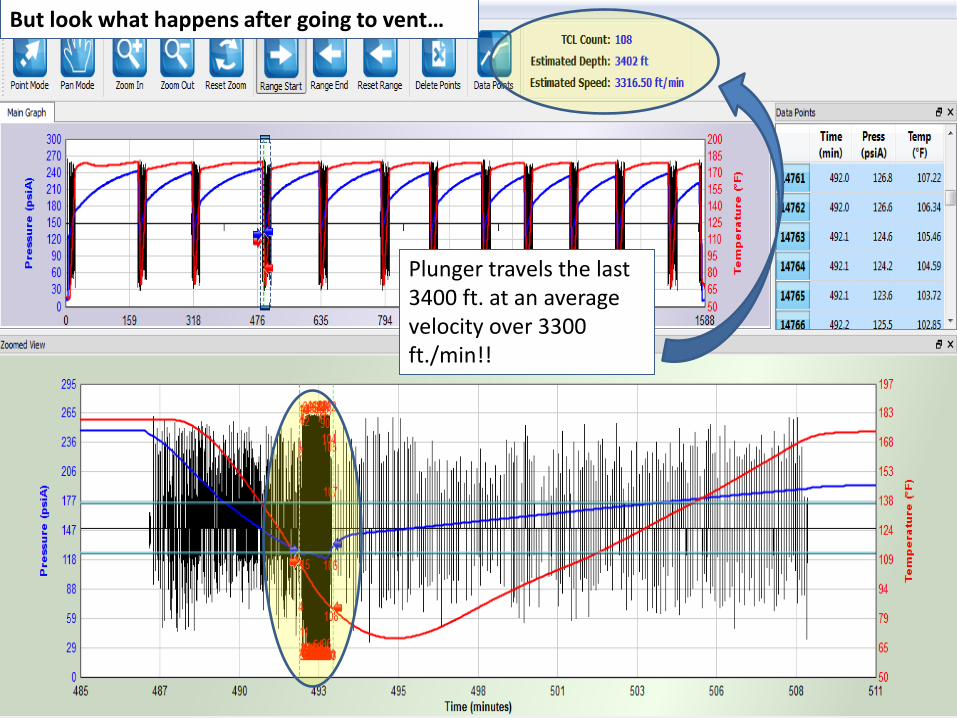
But look what happens after going to vent…
Plunger travels the last 3400 ft. at an average velocity over 3300 ft./min!!

Was Venting Necessary?
• Obviously not!• Bottom hole pressure build rate and
corresponding Casing pressure build rate would show that plunger travel would be reliable without B-valve operation.
• Off time can be cut substantially• May want to add a standing valve to retain
liquid since the horsepower to operate looks good
• Additional cycles per day at lower pressures should enhance production and safety.

Conclusions
• Inspect well location for problems first• Look and listen through a cycle (actual arrival
rate can be vastly different than average trip time indicates!!)
• Inspect plunger for problems or wear• Look for clues in SCADA information• Employ additional diagnostic tools such as an
acoustic device or instrumented plunger to learn more
• Be open to changing the “standard” practice

June 13 – 14, 20112011 Appalachian Basin Gas Well Deliquification Seminar,
Pittsburgh, PA49
CopyrightRights to this presentation are owned by the company(ies) and/or author(s) listed on the title page. By submitting this presentation to the Gas Well Deliquification Workshop, they grant to the Workshop, the Artificial Lift Research and Development Council (ALRDC), and the Southwestern Petroleum Short Course (SWPSC), rights to:
– Display the presentation at the Workshop.– Place it on the www.alrdc.com web site, with access to the site to be as directed
by the Workshop Steering Committee.– Place it on a CD for distribution and/or sale as directed by the Workshop Steering
Committee.Other use of this presentation is prohibited without the expressed written permission of the author(s). The owner company(ies) and/or author(s) may publish this material in other journals or magazines if they refer to the Gas Well Deliquification Workshop where it was first presented.

June 13 – 14, 20112011 Appalachian Basin Gas Well Deliquification Seminar,
Pittsburgh, PA50
DisclaimerThe following disclaimer shall be included as the last page of a Technical Presentation or Continuing Education Course. A similar disclaimer is included on the front page of the Gas Well Deliquification Web Site.
The Artificial Lift Research and Development Council and its officers and trustees, and the Gas Well Deliquification Workshop Steering Committee members, and their supporting organizations and companies (here-in-after referred to as the Sponsoring Organizations), and the author(s) of this Technical Presentation or Continuing Education Training Course and their company(ies), provide this presentation and/or training material at the Gas Well Deliquification Workshop "as is" without any warranty of any kind, express or implied, as to the accuracy of the information or the products or services referred to by any presenter (in so far as such warranties may be excluded under any relevant law) and these members and their companies will not be liable for unlawful actions and any losses or damage that may result from use of any presentation as a consequence of any inaccuracies in, or any omission from, the information which therein may be contained.
The views, opinions, and conclusions expressed in these presentations and/or training materials are those of the author and not necessarily those of the Sponsoring Organizations. The author is solely responsible for the content of the materials.
The Sponsoring Organizations cannot and do not warrant the accuracy of these documents beyond the source documents, although we do make every attempt to work from authoritative sources. The Sponsoring Organizations provide these presentations and/or training materials as a service. The Sponsoring Organizations make no representations or warranties, express or implied, with respect to the presentations and/or training materials, or any part thereof, including any warrantees of title, non-infringement of copyright or patent rights of others, merchantability, or fitness or suitability for any purpose.


