Page 1
i
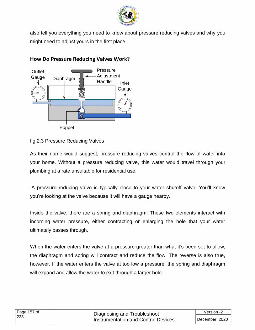
Diagnosing and Troubleshoot Instrumentation
and Control Devices
Based on May, 2011 Version 2 OS and Dec,
2020 Version2 Curriculum
Module Title: Diagnosing and Troubleshoot
Instrumentation and Control Devices
LG Code: EEL ICS3 M05 LO (1-4) LG (16-19)
TTLM Code: EEL ICS3 TTLM 1220 v1
December, 2020
Bishoftu Ethiopia
Page 2
Page ii of 228
Diagnosing and Troubleshoot Instrumentation and Control Devices
Version -2
December 2020
Table of Contents page
LO #1- Plan and prepare for diagnosis of faults of instrumentation and
control systems ......................................................................................... 8
Information Sheet 1- Following OHS policies and procedures ............. 10
1.1 Following OHS policies and procedures. ............................................................ 10
Introduction ............................................................................................. 10
1.1.1 Occupational health......................................................................................... 10
1.1.2 Occupational health and safety ....................................................................... 10
1.1.2 Ethiopian environmental protection proclamations, regulations and standards14
Self-Check -1 ................................................................................................. 20
Information Sheet 2- Following instrumentation and control standards
................................................................................................................. 21
2.1 Following instrumentation and control standards ............................................... 21
2.1.1 Policy statement .............................................................................................. 21
2.1.2 The general OH & S policies and procedures are as follows: ......................... 22
Self-Check -1 ................................................................................................. 24
Information Sheet 3. Gathering and analyzing history cards and
relevant information ................................................................................ 25
3.1 Gathering and analyzing history cards and relevant information ........................ 25
Self-Check 3 ................................................................................................... 34
Information Sheet 4- Obtaining tools, equipment and testing devices
needed to carry out work ........................................................................ 35
Obtaining tools, equipment and testing devices needed to carry out work ............... 35
Self-Check -4 ................................................................................................. 64
Page 3
Page iii of 228
Diagnosing and Troubleshoot Instrumentation and Control Devices
Version -2
December 2020
Information Sheet 5. Consulting appropriate personnel to coordinated
work ......................................................................................................... 66
5.1 Consulting appropriate personnel to coordinated work ...................................... 66
Self-Check 5 ................................................................................................... 69
Information Sheet 6. Checking instrumentation and Control Systems
defects ..................................................................................................... 70
6.1 Checking instrumentation and Control Systems defects .................................... 70
Common Control Loops ........................................................................... 75
Operation title: - loop checking for on / off valves loops ...................... 85
LAP Test .................................................................................................................. 87
Operation title: loop checking Conventional Control Valves Loops ..... 88
Checking Conventional Control Valves Loops ....................................... 91
LAP Test .................................................................................................................. 91
Operation title: loop checking procedure thermocouple / temperature
transmitter loops ..................................................................................... 91
Loop checking procedure thermocouple / temperature transmitter
loops ........................................................................................................ 94
LAP Test .................................................................................................................. 94
Operation title:-loop checking procedure RTD /temperature transmitter
loops ........................................................................................................ 95
loop checking procedure RTD /temperature transmitter loops ............ 97
LAP Test .................................................................................................................. 97
Page 4
Page iv of 228
Diagnosing and Troubleshoot Instrumentation and Control Devices
Version -2
December 2020
Operation title: - switches loops checking (flow, level, pressure,
temperature) ............................................................................................ 98
LAP Test ................................................................................................................ 100
Operation title: vibration loops (with proximitors) loop checking
procedure .............................................................................................. 101
LAP Test ................................................................................................................ 104
6.1.1 Pressure measurement and control loop .......................................... 104
6.1.2 Level measurement and control loop .................................................. 105
6.1.2 Flow measurement and control loop ................................................. 106
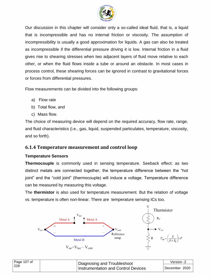
6.1.4 Temperature measurement and control loop ...................................... 107
6.1.5 Analytical measurement and control loop ............................................ 108
Control Loop Analysis ........................................................................... 108
Control loop analysis system .................................................................................. 108
Oscilloscope-based response measurement setup ................................................ 109
Probe characteristics for control loop measurements ............................................ 109
Self-Check 6 ................................................................................................. 111
Information Sheet 7. Planning and preparing diagnosis of faults ...... 112
Planning and preparing diagnosis of faults ............................................................ 112
Self-Check 7 ................................................................................................. 114
LO #2- Diagnose faults of instrumentation and control systems ........ 116
Information Sheet 1 Using appropriate personal protective equipment
............................................................................................................... 118
1.1 Using appropriate personal protective equipment ............................................ 118
Self-Check 1 ................................................................................................. 120
Information Sheet 2 Diagnosing faults or problems in instrumentation
and control systems .............................................................................. 121
2.1 Diagnosing faults or problems in instrumentation and control systems ............ 121
Paper-based or Electronic ............................................................................ 122
2.1.1 Troubleshooting ................................................................................... 122
Page 5
Page v of 228
Diagnosing and Troubleshoot Instrumentation and Control Devices
Version -2
December 2020
2.1.2 Principle troubleshooting ..................................................................... 122
2.1.3 Sources of failure or poor performance in an instrument system ........ 124
Self-Check 2 ................................................................................................. 134
Information Sheet 3. Managing contingency measures during
unplanned events or conditions ........................................................... 135
3.1 Managing contingency measures during unplanned events or conditions ....... 135
Self-Check .3 ................................................................................................ 138
Information Sheet 4. Recording fault and diagnosis results ............... 139
Recording fault and diagnosis results .................................................................... 139
Self-Check 4 ................................................................................................. 143
LO #3 Rectify/correct defects in instrumentation control devices and
system ................................................................................................... 144
Information Sheet1. Identifying appropriate shutdown procedure ..... 146
Self-Check 1 ................................................................................................. 154
Information Sheet-2. Making adjustments ........................................... 155
2.1 Making adjustments ........................................................................................ 155
Self-Check 2 ................................................................................................. 161
Information Sheet 3. Replacing or correcting defective components or
parts ....................................................................................................... 162
3.1 Replacing or correcting defective components or parts ................................... 162
Self-Check 3 ................................................................................................. 163
Information Sheet-4. Responding to unplanned events or conditions 164
4.1 Responding to unplanned events or conditions ................................................ 164
Self-Check 4 ................................................................................................. 166
Information Sheet-5. Recording rectified/corrected defects/
malfunctions components and measures ........................................... 167
Page 6
Page vi of 228
Diagnosing and Troubleshoot Instrumentation and Control Devices
Version -2
December 2020
5.1 Recording rectified/corrected defects/ malfunctions components and measures
............................................................................................................................... 167
Table 1 Recording rectified/corrected defects components and
measures ............................................................................................... 168
Self-Check 5 ................................................................................................. 170
LO #4 Testing corrected instrumentation and control systems ......... 171
Information Sheet1. Testing Instrumentation & control systems ...... 172
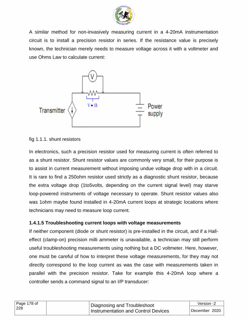
1.1 Testing Instrumentation & control systems ....................................................... 172
1.1.1Troubleshooting current loops .............................................................. 172
1.1.2 Sensors ............................................................................................... 185
1.1.3 Programmable logic controllers ........................................................... 186
1.1.4 Control valves and final control elements ............................................ 186
1.3.4 Computer operations ........................................................................... 187
1.3.5 Process and machinery operation ....................................................... 187
Self-Check 1 ................................................................................................. 188
Information Sheet-2. Recording test results ........................................ 189
2.1 Test Results Recording Sheet ........................................................ 189
Self-Check 2 ................................................................................................. 192
Information Sheet 3. Preparing and completing reports ..................... 193
Self-Check 3 ................................................................................................. 202
Operation title: -Diagnosing and Troubleshoot Instrumentation and
Control Devices ..................................................................................... 203
Diagnosing and troubleshoot instrumentation and Control Devices .. 206
LAP Test ................................................................................................................ 206
Answer Key for self-check ............................................................................ 207
REFERENCES ......................................................................................... 225
Page 7
Page vii of 228
Diagnosing and Troubleshoot Instrumentation and Control Devices
Version -2
December 2020
AKNOWLEDGEMENT ................................... Error! Bookmark not defined.
Page 8
Page 8 of 228
Diagnosing and Troubleshoot Instrumentation and Control Devices
Version -2
December 2020
L #16 LO #1- Plan and prepare for diagnosis of faults of instrumentation and
control systems
Instruction sheet
This learning guide is developed to provide you the necessary information regarding the
following content coverage and topics:
Following OHS policies and procedures
Following instrumentation and control standards
Gathering and analyzing history cards and relevant information
Obtaining tools, equipment and testing devices needed to carry out work
Consulting appropriate personnel to coordinated work
Checking instrumentation and Control Systems defects
Planning and preparing diagnosis of faults
This guide will also assist you to attain the learning outcomes stated in the cover page.
Specifically, upon completion of this learning guide, you will be able to:
Follow OHS policies and procedures
Follow instrumentation and control standards
Gather and analyze history cards and relevant information
Obtain tools, equipment and testing devices needed to carry out work
Consult appropriate personnel to coordinated work
Check instrumentation and Control Systems defects
Plan and prepare diagnosis of faults
Page 9
Page 9 of 228
Diagnosing and Troubleshoot Instrumentation and Control Devices
Version -2
December 2020
Learning Instructions:
1. Read the specific objectives of this Learning Guide.
2. Follow the instructions described below.
3. Read the information written in the ―Information Sheets‖. Try to understand what are
being discussed. Ask your trainer for assistance if you have hard time understanding
them.
4. Accomplish the ―Self-checks‖ which are placed following all information sheets.
5. Ask from your trainer the key to correction (key answers) or you can request your
trainer to correct your work. (You are to get the key answer only after you finished
answering the Self-checks).
Page 10
Page 10 of 228
Diagnosing and Troubleshoot Instrumentation and Control Devices
Version -2
December 2020
1.1 Following OHS policies and procedures.
Introduction
A health and safety program is a definite plan of action designed to prevent accidents
and occupational diseases.. A health and safety program must include the elements
required by the health and safety legislation as a minimum. Because organizations
differ, a program developed for one organization cannot necessarily be expected to
meet the needs of another. This document summarizes the general elements of a
health and safety program.
1.1.1 Occupational health
occupational health is defined as the science and art devoted to the anticipation,
recognition, evaluation and control of those environmental factors or stresses, arising in
or from the place of work, which may cause illness, impaired health and well being, or
significant discomfort and inefficiency among workers or among citizens of the
community.
Industrial hygiene has been described as the ―promotion and maintenance of the
highest degree of physical, mental and social well-being of workers in all occupations by
preventing departures from health, controlling risks and the adaptation of work to
people, and people to their jobs.
1.1.2 Occupational health and safety
Occupational health and safety is a discipline with a broad scope involving many
specialized fields. In its broadest sense, it aims at:
The promotion and maintenance of the highest degree of physical, mental and
social well- being of workers in all occupation;
Information Sheet 1- Following OHS policies and procedures
Page 11
Page 11 of 228
Diagnosing and Troubleshoot Instrumentation and Control Devices
Version -2
December 2020
The prevention among workers of adverse effect on health caused by their working
conditions;
The protection of workers in their employment from risks resulting from factors
adverse to health;
The placing and maintenance of workers in an occupational environment adopted
to physical and mental needs;
The adaptation of work to humans. Successful occupational health and safety
practice requires the collaboration and participation of both employers and workers
in health and safety programmes, and involves the collaboration of issues relating
to occupational medicine, industrial hygiene toxicology, education, ergonomics,
engineering safety, psychology, etc
OHS guidelines
Guide line is an explanatory document providing detailed information on the
requirement of legislation, regulation, standards, codes of practice or matters relating to
occupational health and safety
the guide line although not intended as a regulatory instrument, is based on the
regulatory frame work and provides information on necessary acceptable practice to
achieve regulatory compliance , in many cases the guidelines will provide interpretation
of intent of the legislation and describe the rational used in its development it may
provide proactive programs or services that the regulatory and legislative requirement
A national framework for occupational safety and health management systems
National policy
A competent institution or institutions should be nominated, as appropriate, to
formulate, implement and periodically review a coherent national policy for the
establishment and promotion of OSH management systems in organizations. This
should be done in consultation with the most representative organizations of employers
and workers, and with other bodies as appropriate.
The national policy on OSH management systems should establish general principles
and procedures to:
Page 12
Page 12 of 228
Diagnosing and Troubleshoot Instrumentation and Control Devices
Version -2
December 2020
a) promote the implementation and integration of OSH management systems as
part
b) of the overall management of an organization;
a) facilitate and improve voluntary arrangements for the systematic identification,
planning, implementation and improvement of OSH activities at national and
organization levels;
b) promote the participation of workers and their representatives at organization
level;
c) implement continual improvement while avoiding unnecessary bureaucracy,
administration and costs;
d) promote collaborative and support arrangements for OSH management systems
at the organization level by labour inspectorates, occupational safety and health
services and other services, and channel their activities into a consistent
framework for OSH management;
e) evaluate the effectiveness of the national policy and framework at appropriate
intervals;
f) evaluate and publicize the effectiveness of OSH management systems and
practice by suitable means; and
g) ensure that the same level of safety and health requirements applies to
contractors and their workers as to the workers, including temporary workers,
employed directly by the organization.
With a view to ensuring the coherence of the national policy and of arrangements for its
implementation, the competent institution should establish a national framework for
OSH management systems to:
a) identify and establish the respective functions and responsibilities of the various
institutions called upon to implement the national policy, and make appropriate
arrangements to ensure the necessary coordination between them;
b) publish and periodically review national guidelines on the voluntary application
and systematic implementation of OSH management systems in organizations;
establish criteria, as appropriate, for the designation and respective duties of the
Page 13
Page 13 of 228
Diagnosing and Troubleshoot Instrumentation and Control Devices
Version -2
December 2020
institutions responsible for the preparation and promotion of tailored guidelines
on OSH management systems; and
c) ensure that guidance is available to employers, workers and their representatives
to take advantage of the national policy.
The competent institution should make arrangements and provide technically sound
guidance to labour inspectorates, OSH services and other public or private services,
agencies and institutions dealing with OSH, including health-care providers, to
encourage and help organizations to implement OSH management systems.
Occupational safety and health policy
The employer, in consultation with workers and their representatives, should set out in
writing an OSH policy, which should be:
(a) specific to the organization and appropriate to its size and the nature of its activities;
(b) concise, clearly written, dated and made effective by the signature or endorsement
of the employer or the most senior accountable person in the organization;
(c) communicated and readily accessible to all persons at their place of work;
(d) reviewed for continuing suitability; and
(e) made available to relevant external interested parties, as appropriate.
The OSH policy should include, as a minimum, the following key principles and
objectives to which the organization is committed:
(a) protecting the safety and health of all members of the organization by preventing
work-related injuries, ill health, diseases and incidents;
(b) Complying with relevant OSH national laws and regulations, voluntary programmes,
collective agreements on OSH and other requirements to which the organization
subscribes;
(c) Ensuring that workers and their representatives are consulted and encouraged to
participate actively in all elements of the OSH management system; and
(d) Continually improving the performance of the OSH management system.
Page 14
Page 14 of 228
Diagnosing and Troubleshoot Instrumentation and Control Devices
Version -2
December 2020
The OSH management system should be compatible with or integrated in other
management systems in the organization.
Occupational safety and health objectives
Consistent with the OSH policy and based on the initial or subsequent reviews,
measurable OSH objectives should be established, which are:
a) specific to the organization, and appropriate to and according to its size and
nature of activity;
b) consistent with the relevant and applicable national laws and regulations, and the
technical and business obligations of the organization with regard to OSH;
c) focused towards continually improving workers' OSH protection to achieve the
best OSH performance;
d) realistic and achievable;
e) documented, and communicated to all relevant functions and levels of the
organization; and
f) periodically evaluated and if necessary updated
1.1.2 Ethiopian environmental protection proclamations, regulations and
standards
Proclamation on Environmental Impact Assessment
The Federal Government has issued a Proclamation on Environmental Impact
Assessment (Proc. No. 299/2002) and the primary aim of this Proclamation is to make
EIA mandatory for specified categories of activities undertaken either by the public or
private sectors, and possibly, the extension of EIA to policies, plans and programs in
addition to projects. Categories of projects that will require full EIA, not full EIA or no EIA
are provided. To effect the requirements of this Proclamation, the former EPA, now
MoEFCC, issued a Procedural and Technical EIA Guidelines, which provide details of
the EIA process and its requirements.\
This legislation may be triggered by the proposed Addis Ababa Transmission and
Distribution System Rehabilitation and Upgrading Project as certain components of the
project are expected to fall under the category of projects that require full EIA or
preliminary environmental assessment (PEA). The project components that will require
full EIA (ESIA) or PEA will be identified in the Screening process.
Page 15
Page 15 of 228
Diagnosing and Troubleshoot Instrumentation and Control Devices
Version -2
December 2020
Proclamation on Environmental Pollution Control
The Proclamation on Environmental Pollution Control (Proc. No. 300/2002) is mainly
based on the right of each citizen to a healthy environment, as well as on the obligation
to protect the environment of the Country. The primary objective of this law is to provide
the basis from which the relevant ambient environmental standards applicable to
Ethiopia can be developed, and to make the violation of these standards a punishable
act. The Proclamation states that the ―polluter pays‖ principle will be applied to all
persons.
This legislation may be triggered by the subject project since it may cause some
environmental pollution. Therefore, the Project Proponent/EEP and its Contractor(s) are
responsible for preventing environmental pollution and taking remedial measures for
any incidents that may occur during the project implementation.
Proclamation on Energy
Energy Proclamation (No. 810/2013) was issued in January 2014 to revise the
Electricity Proclamation No.86/1997 based on the up-to-date national and regional
development of energy regulations. The proclamation, under Article 4, provides the
powers and duties of the Ethiopian Energy Authority (EEA), which was established by
the Council of Ministers Regulation No.308/2014. The powers and duties of EEA,
among several others, include the following:
issue and renew license and certificate of competency in accordance with this
Proclamation and regulations and directives issued hereunder;
supervise the operations of licensees and holders of certificates of competency to
ensure compliance with the provisions of this Proclamation and regulations and
directives issued hereunder;
formulate long-term, medium-term, and short-term energy efficiency and
conservation strategy and program at national and sectoral levels;
issue energy audit code, energy efficiency standards code, energy efficiency
labeling code, grid code, customers' service code, technical inspection code, quality
service standard code, building electrical installation code, technical standard code
and other codes; and supervise the implementations of same;
approve electric power purchase and network service agreements;
Page 16
Page 16 of 228
Diagnosing and Troubleshoot Instrumentation and Control Devices
Version -2
December 2020
may enter the land or the premises in the holding of any person after securing prior
permission from the person to carry out installation of new electricity supply, or to carry
out activities required to connect, repair, upgrade, inspect or remove electrical lines;
shall have the right to cut or lop trees or to remove crops, plants or other things that
obstruct the construction or operation of electrical works or may cause danger to
electrical lines.
Article 17 deals with Compensation issue and states that the licensee shall pay
compensation, in accordance with the relevant law, for damages caused to the property
of a landholder while performing the activities provided under Article 16 of this
Proclamation.
Article 18 contains provisions on Expropriation of Land and it states that where public
interest so justifies, any generation, transmission, distribution and sale, import or export
licensee may be made the beneficiary of an expropriation measure, taken in
accordance with the relevant law, by the government over private land holdings.
Regulations on Electricity Operations
This Council of Ministers Regulations No. 49/1999 was issued in 1999 pursuant to
Article 28(1) of the Electricity Proclamation No. 86/1997 to provide the regulations of
electricity operations in the country. The Regulations are divided into six parts, which
include requirements for Electricity Operation Licenses; Rights and Obligations of
Licensees and Customers; Electricity Price and Tariff; Standards of Safety, Technical
and Quality of Service; and Miscellaneous Provisions. The provisions most relevant for
the subject project are described below.
As part of the general safety requirements, Sub-article 47(1) prohibits undertaking any
type of construction work or growing trees under electric power lines or within the
distance of horizontal clearance thereof. Under the safety requirements for
Transmission Lines and Substations, Article 58 provides the requirements for Clearance
from Buildings and Structures. Sub-article (1) states that the horizontal distance from
conductors to any point of a building or structure shall, with maximum wind, be at least
4.5 meters. If the requirement stated under Sub-Article (1) cannot be fulfilled, the height
of the conductor from the building or structure shall, at maximum temperature and with
Page 17
Page 17 of 228
Diagnosing and Troubleshoot Instrumentation and Control Devices
Version -2
December 2020
conductor broken in the neighboring span, be at least 5.5 meters. Similarly Article 59
provides the safety requirements for Clearance from Trees. According to Sub-article (1)
the vertical distance of conductors from trees shall be at least 1.5 meters plus the
minimum distance between live and un-energized parts. In the case of fruit trees the
distance shall be 4m plus the minimum distance between live and un-energized parts as
per Sub-article (2). The distances stated above shall be maintained in accordance with
the expected growth of trees (Sub-article 3).
Importance of Occupational Health and Safety
Work plays a central role in people’s lives, since most workers spent at least eight hours
a day in the work place. Therefore, work environment should be safe and healthy.
Yet this is not the case for many workers. Every day workers all over the world are
faced with a multitude of health hazards, such as; dusts, gasses, noise, vibration,
extreme temperature, etc.
The scope of occupational health and safety include:
Recognition and anticipation of workers health problems in an industrial
atmosphere;
Evaluation of the recognized problem which encompasses mainly data collection,
analysis, interpretation, and recognition;
Development of corrective actions to eliminate or limit the problem.
Generally, the work frame of industrial hygiene is wide and needs multidisciplinary
approach. It requires the knowledge of physics, biology, chemistry, ergonomics,
medicine, engineering and related science. It also requires public health
management skills for proper communication and decision making.
Some common hazards that may be encountered in the workplace include:
Chemical Hazards
These include asbestos, coal dust, multitude of acids and alkalis, gases such as SO2,
CO2, CO, NOx, heavy metal poisonings such as lead and mercury and a long list of toxic
substances such as pesticides, solvents and preservatives. These harmful chemical
compounds in the form of solids, liquids, gases, mists, dusts, fumes, and vapor exert toxic
Page 18
Page 18 of 228
Diagnosing and Troubleshoot Instrumentation and Control Devices
Version -2
December 2020
effects after they get entrance by inhalation, absorption through direct contact with skin or
ingestion. The most important of these is inhalation due to the speed with which toxic
substances are absorbed and enter the blood stream. Please note that the degree of
worker risk from exposure to any given substances depends on the nature and potency of
the toxic effects and the magnitude and duration of exposure.
Biological Hazards
These include bacteria, virus, fungi, and other living organisms that can cause acute and
chronic infections.
Physical Hazards
• Non-ionizing radiation e.g. microwaves, infra red, visible and ultra-violet light
• Ionizing radiation e.g. X-rays, gamma rays, beta particles, alpha particles from
radon daughters
• Noise (usually measured in decibels dB) and vibration;
• Temperature, humidity etc
Ergonomic Hazards
The term is originated from two Greek words, ergon- meaning work and nomos meaning
law. Ergonomics is, therefore, the study of law(s) governing work and its environment.
Ergonomics includes human factors in engineering and it deals with the consideration of
human characteristics, expectations and behaviors in the design of tools, equipment etc
that people use in their work and everyday lives and the environment in which they work
and live. Ergonomics related injuries and illness are ranging from eyestrain and
headaches, musculoskeletal ailments such as chronic backache, neck and shoulder pain,
etc. These and other related problems are avoided primarily by the effective design of a
job or jobsite and by better- designed tools or equipment that meet workers needs in terms
of physical environment and job tasks
Psychosocial Hazards
Page 19
Page 19 of 228
Diagnosing and Troubleshoot Instrumentation and Control Devices
Version -2
December 2020
The term ―stress‖ means the strain imposed on the worker by psychosocial influences
associated with urbanization and works. Within the work environment itself, emotional
stress may arise from a variety of psychosocial factors, which the worker finds
unsatisfactory, frustrating or demoralizing, for example: Workers may be working in shifts
that will expose them to unusual hours. They may upset their family’s life as a result of
their work conditions.
Workers may be working with a person who is paid more but who is incapable of working.
Financial incentives are too low, work overload, work under load, poor job management,
career development, and lack of job security, etc
Page 20
Page 20 of 228
Diagnosing and Troubleshoot Instrumentation and Control Devices
Version -2
December 2020
Self-Check -1 Written Test
Directions: Answer all the questions listed below. Use the Answer sheet
provided
I. Answer the following question as directed below
1. ______________is defined as the science and art devoted to the anticipation,
recognition, evaluation and control of those environmental factors or stresses,
arising in or from the place of work, which may cause illness, impaired health
and well being(2%)
2. --------- is the ―promotion and maintenance of the highest degree of physical,
mental and social well-being of workers in all occupations by preventing
departures from health. (2%)
3. Write at least three aim of Occupational health and safety (2%)
4. ____________is a material measure or physical property that defines or
reproduces the unit of measurement of a base or derived quantity(2%)
5. ISA stands for (2%)
6. ___________(American National Standards Institute) (2%)
7. ASME stands for (2%)
8. NEC stands for (2%)
Answer the following question!
Note: Satisfactory rating - 8and 16points Unsatisfactory - below 9and 16
points
You can ask you teacher for the copy of the correct answers.
Answer Sheet
Name: _________________________ Date: ______________
Score = ___________
Rating: ____________
Page 21
Page 21 of 228
Diagnosing and Troubleshoot Instrumentation and Control Devices
Version -2
December 2020
Information Sheet 2- Following instrumentation and control standards
2.1 Following instrumentation and control standards
Instrumentation and Control Standards Includes but not limited to Standard
A standard is a material measure or physical property that defines or reproduces the
unit of measurement of a base or derived quantity. However, a standard also needs to
be checked against a higher standard to establish its accuracy and traceability. Since
the same argument would hold good even for the higher standard, this hierarchy of
standards must lead to a level above which comparison is not possible.
Regulations for consumers’ electrical installations, 1969, issued by Ethiopian
Electric Light and power Authority (EELPA), (now EEPCo)
OIML (International Organization for Legal Metrology) Standards) or ES
ISA (Instrumentation, Systems and Automation) Society (formerly Instrument
Society of America)
ANSI(American National Standards Institute)
ASME (American Society of Mechanical Engineers)
NEC (National Electrical Code)
2.1.1 Policy statement
An organization's occupational health and safety policy is a statement of principles and
general rules that serve as guides for action. Senior management must be committed to
ensuring that the policy is carried out with no exceptions. The health and safety policy
should have the same importance as the other policies of the organization.
The policy statement can be brief, but it should mention:
Management's commitment to protect the safety and health of employees.
The objectives of the program.
The organization's basic health and safety philosophy.
Who is accountable for occupational health and safety programs.
Page 22
Page 22 of 228
Diagnosing and Troubleshoot Instrumentation and Control Devices
Version -2
December 2020
The general responsibilities of all employees.
That health and safety shall not be sacrificed for expediency.
That unacceptable performance of health and safety duties will not be tolerated.
The policy should be:
Stated in clear, unambiguous, and unequivocal terms.
Signed by the incumbent Chief Executive Officer.
Kept up-to-date.
Communicated to each employee.
Adhered to in all work activities.
The following is an example of an occupational health and safety policy statement:
2.1.2 The general OH & S policies and procedures are as follows:
No person shall be required or instructed to work in surroundings or under
conditions that are unsafe or dangerous to his or her health.
The employer shall be responsible for initiating and maintaining a safety and
health program that complies with the US Army Corps of Engineers (USACE)
safety and health requirements.
Each employee is responsible for complying with applicable safety and
occupational health requirements, wearing prescribed safety and health
equipment, reporting unsafe conditions/activities, preventing avoidable accidents,
and working in a safe manner.
Safety and health programs, documents, signs, and tags shall be communicated
to employees in a language that they understand.
Worksites with non-English speaking workers shall have a person(s), fluent in the
language(s) spoken and English, on site when work is being performed, to
translate as needed.
The Contractor shall erect and maintain a safety and health bulletin board in an
area commonly accessed by workers. The bulletin board shall be maintained
current, in clear view of on- site workers; and protected against the elements and
Page 23
Page 23 of 228
Diagnosing and Troubleshoot Instrumentation and Control Devices
Version -2
December 2020
unauthorized removal. It shall contain at least the following safety and health
information
General Safety Guidelines:
Follow the basic safety guidelines to prevent cuts, burns, electrical shock, and damage
to eyesight. As a best practice here are some general safety guidelines:
Remove your watch or any other jewelry and secure loose clothing.
Turn off the power and unplug equipment before opening the case and
performing service.
Cover any sharp edges inside the computer case with tape.
Never open a power supply.
Know where the fire extinguisher is located and how to use it.
Know where the first aid kit is located.
Keep food and drinks out of your workspace.
Keep your workspace clean and free of clutter.
Lift heavy objects with your legs to avoid back injury.
Page 24
Page 24 of 228
Diagnosing and Troubleshoot Instrumentation and Control Devices
Version -2
December 2020
Self-Check -1 Written Test
Directions: Answer all the questions listed below. Use the Answer sheet provided in the
next page:
I. Answer the following question as directed below each (2%)
1. Write at least four personal protective equipment
2. ----------- is used for ear protection
3. What is the purpose of goggles/glasses
4. Workers should wear ------------- when working aboveground on building to
protect head in which work is being done.
5. ------------- is worn to avoid such situations.
6. What is the purpose of safety belt/harness.
7. Employees should wear --------- for protecting feet while working or walking on
job location.
8. ------------ are used in operations where in it becomes imperative to protect ones
hands.
Answer the following question!
Note: Satisfactory rating 9 and 16 points Unsatisfactory - below 9and 16points
You can ask you teacher for the copy of the correct answers.
Answer Sheet
Name: _________________________ Date: _______________
Score = ___________
Rating: ____________
Page 25
Page 25 of 228
Diagnosing and Troubleshoot Instrumentation and Control Devices
Version -2
December 2020
Information Sheet 3. Gathering and analyzing history cards and relevant
information
3.1 Gathering and analyzing history cards and relevant information
Gathering and analyzing history card and relevant information help the technician to get
full information about its work and to perform it works perfectly
Before you begin to troubleshoot any piece of equipment, you must be familiar with your
organization’s safety rules and procedures for working on electrical equipment. These
rules and procedures govern the methods you can use to troubleshoot electrical
equipment (including your lockout/ tagout procedures, testing procedures etc.) and must
be followed while troubleshooting.
Next, you need to gather information regarding the equipment and the problem. Be sure
you understand how the equipment is designed to operate. It is much easier to analyze
faulty operation when you know how it should operate. Operation or equipment manuals
and drawings are great sources of information and are helpful to have available. If there
are equipment history records, you should review them to see if there are any recurring
(chronic) problems. You should also have on-hand any documentation describing the
problem. (i.e., a work order, trouble report, or even your notes taken from a discussion
with a customer.)
Gathering information describe the process of acquiring knowledge .it is not the
knowledge it self
There are different methods of information gathering
Questionnaires ,surveys and checklist
Personal interview
Observation
Focus group
Case study
Page 26
Page 26 of 228
Diagnosing and Troubleshoot Instrumentation and Control Devices
Version -2
December 2020
Data analysis is a process of inspecting, cleansing, transforming, and modeling data
with the goal of discovering useful information, informing conclusions, and supporting
decision making
Data integration is precursor to data analysis and data analysis is closely linked to data
visualization and data dissemination
Steps for gathering information
Step 1 observation
Step 2 define problem area
Step 3 identify possible causes
Step 4 determine most probable cause
Step 5 test and repair
Step 6 follow-up
Step 1 – Observe
Most faults provide obvious clues as to their cause. Through careful observation and a
little bit of reasoning, most faults can be identified as to the actual component with very
little testing. When observing malfunctioning equipment, look for visual signs of
mechanical damage such as indications of impact, scratched wires, loose components
or parts lying in the bottom of the cabinet. Look for signs of overheating, especially on
wiring, relay coils, and printed circuit boards.
Don't forget to use your other senses when inspecting equipment. The smell of burnt
insulation is something you won't miss. Listening to the sound of the equipment
operating may give you a clue to where the problem is located. Checking the
temperature of components can also help find problems but be careful while doing this,
some components may be alive or hot enough to burn you.
Page 27
Page 27 of 228
Diagnosing and Troubleshoot Instrumentation and Control Devices
Version -2
December 2020
Pay particular attention to areas that were identified either by past history or by the
person that reported the problem. A note of caution here! Do not let these mislead you,
past problems are just that – past problems, they are not necessarily the problem you
are looking for now. Also, do not take reported problems as fact, always check for
yourself if possible. The person reporting the problem may not have described it
properly or may have made their own incorrect assumptions.
When faced with equipment which is not functioning properly you should:
Be sure you understand how the equipment is designed to operate. It makes it
much easier to analyze faulty operation when you know how it should operate;
Note the condition of the equipment as found. You should look at the state of the
relays (energized or not), which lamps are lit, which auxiliary equipment is
energized or running etc. This is the best time to give the equipment a thorough
inspection (using all your senses). Look for signs of mechanical damage,
overheating, unusual sounds, smells etc.;
Test the operation of the equipment including all of its features. Make note of any
feature that is not operating properly. Make sure you observe these operations
very carefully. This can give you a lot of valuable information regarding all parts
of the equipment.
Step 2 – Define Problem Area
It is at this stage that you apply logic and reasoning to your observations to determine
the problem area of the malfunctioning equipment. Often times when equipment
malfunctions, certain parts of the equipment will work properly while others not.
The key is to use your observations (from step 1) to rule out parts of the equipment or
circuitry that are operating properly and not contributing to the cause of the malfunction.
You should continue to do this until you are left with only the part(s) that if faulty, could
cause the symptoms that the equipment is experiencing.
Page 28
Page 28 of 228
Diagnosing and Troubleshoot Instrumentation and Control Devices
Version -2
December 2020
To help you define the problem area you should have a schematic diagram of the circuit
in addition to your noted observations.
Starting with the whole circuit as the problem area, take each noted observation and
ask yourself "what does this tell me about the circuit operation?" If an observation
indicates that a section of the circuit appears to be operating properly, you can then
eliminate it from the problem area. As you eliminate each part of the circuit from the
problem area, make sure to identify them on your schematic. This will help you keep
track of all your information.
Step 3 – Identify Possible Causes
Once the problem area(s) have been defined, it is necessary to identify all the possible
causes of the malfunction. This typically involves every component in the problem
area(s).
It is necessary to list (actually write down) every fault which could cause the problem no
matter how remote the possibility of it occurring. Use your initial observations to help
you do this. During the next step you will eliminate those which are not likely to happen.
Step 4 – Determine Most Probable Cause
Once the list of possible causes has been made, it is then necessary to prioritize each
item as to the probability of it being the cause of the malfunction. The following are
some rules of thumb when prioritizing possible causes.
Although it could be possible for two components to fail at the same time, it is not very
likely. Start by looking for one faulty component as the wrong.
The following list shows the order in which you should check components based
on the probability of them being defective:
First look for components which burn out or have a tendency to wear out, i.e.
mechanical switches, fuses, relay contacts, or light bulbs. (Remember, that in the
Page 29
Page 29 of 228
Diagnosing and Troubleshoot Instrumentation and Control Devices
Version -2
December 2020
case of fuses, they burn out for a reason. You should find out why before
replacing them.)
The next most likely cause of failure are coils, motors, transformers and other
devices with windings. These usually generate heat and, with time, can
malfunction.
Connections should be your third choice, especially screw type or bolted type.
Over time these can loosen and cause a high resistance. In some cases this
resistance will cause overheating and eventually will burn open. Connections on
equipment that is subject to vibration are especially flat to coming loose.
Finally, you should look for is defective wiring. Pay particular attention to areas
where the wire insulation could be damaged causing short circuits. Don't rule out
incorrect wiring, especially on a new piece of equipment.
Step 5 – Test and Repair
Testing electrical equipment can be hazardous. The electrical energy contained in many
circuits can be enough to injure or kill. Make sure you follow all your companies’ safety
precautions, rules and procedures while troubleshooting. Once you have determined
the most probable cause, you must either prove it to be the problem or rule it out. This
can sometimes be done by careful inspection however, in many cases the fault will be
such that you cannot identify the problem component by observation and analysis
alone. In these circumstances, test instruments can be used to help narrow the problem
area and identify the problem component. There are many types of test instruments
used for troubleshooting. Some are specialized instruments designed to measure
various behaviors of specific equipment, while others like the multimeters are more
general in nature and can be used on most electrical equipment. A typical multimeter
can measure AC and DC Voltages, Resistance, and Current.
A very important rule when taking meter readings is to predict what the meter will read
before taking the reading. Use the circuit schematic to determine what the meter will
read if the circuit is operating normally. If the reading is anything other than your
predicted value, you know that this part of the circuit is being affected by the fault.
Page 30
Page 30 of 228
Diagnosing and Troubleshoot Instrumentation and Control Devices
Version -2
December 2020
Depending on the circuit and type of fault, the problem area as defined by your
observations, can include a large area of the circuit creating a very large list of possible
and probable causes. Under such circumstances, you could use a ―divide and eliminate‖
testing approach to eliminate parts of the circuit from the problem area. The results of
each test provides information to help you reduce the size of the problem area until the
defective component is identified.
Once you have determined the cause of the faulty operation of the circuit you can
proceed to replace the defective component. Be sure the circuit is locked out and you
follow all safety procedures before disconnecting the component or any wires.
After replacing the component, you must test operate all features of the circuit to be
sure you have replaced the proper component and that there are no other faults in the
circuit. It can be very uncomfortable to tell the customer that you have repaired the
problem only to have him find another problem with the equipment just after you leave.
Follow up: Although this is not an official step of the troubleshooting process it
nevertheless should be done once the equipment has been repaired and put back in
service. You should try to determine the reason for the malfunction.
Did the component fail due to age?
Did the environment the equipment operates in cause excessive corrosion?
Are there wear points that caused the wiring to short out?
Did it fail due to improper use?
Is there a design error that causes the same component to fail repeatedly?
Through this process further failures can be minimized. Many organizations have their
own follow-up documentation and processes. Make sure you check your organization’s
procedures. Adopting a logical and systematic approach
You must be able to:
Page 31
Page 31 of 228
Diagnosing and Troubleshoot Instrumentation and Control Devices
Version -2
December 2020
work safely at all times, complying with health and safety legislation, regulations
and the relevant guidelines
plan the maintenance activities before you start them
obtain all the information you need for the safe removal and replacement of the
instruments and/or sensors
obtain and prepare the appropriate tools and equipment
apply appropriate maintenance diagnostic techniques and procedures
use the appropriate methods and techniques to remove and replace the required
instruments/sensors
carry out tests on sensing elements and associated instruments
deal promptly and effectively with problems within your control, and seek help
and guidance from the relevant people if you have problems that you cannot
resolve
leave the work area in a safe and tidy condition on completion of the
maintenance activities
Proceed by asking questions and finding answers to them.
State questions as simply as possible. Select questions which can be answered easily
and will provide the maximum information to help find the fault. Answer the questions by
Thinking, Observing, and Testing. Refer to experts, manufacturers, or agents. Check
manuals, text books, catalogs, technical data sources. etc.
1. Make observations, tests, etc. from the simple to the complex, but always do the
simple things first.
2. Think about failure the degree of failure, the causes of failure, the time course of
the failure, and the combinations of failure. In other words, given the information
at hand:
a. What is most likely to have failed?
b. What was the most probable cause of the failure?
c. How can the fault and the cause be corrected?
3. Keep records
Page 32
Page 32 of 228
Diagnosing and Troubleshoot Instrumentation and Control Devices
Version -2
December 2020
History card preparation
History card Perfect instrumentation control
Tag no PG-01
ID No 1-003
description Pressure gage
Maker Fibig
Range 0 to 60Kg/cm2
Accuracy */- 0.35%
Location Lab Work
description
remark Due date
SR NO 04 oct 11 calibrated Ok 10 apr
05 apr 11 Replaced
part
ok -
Page 33
Page 33 of 228
Diagnosing and Troubleshoot Instrumentation and Control Devices
Version -2
December 2020
TO CALIBRATE A VALVE:
1. Place the loop in manual with a 0% output. Adjust the valve zero until the valve is at
its full de-energized position.
2. Set the manual output at 100%. Adjust the valve span until the valve is at its full
energized position.
3. Set the manual output at 50%. Verify that the valve is at its 50% position.
If a loop has been tuned with an improperly calibrated valve, recalibration may
change the
process gain requiring retuning of the control loop.
Check the valve dead band. Excessive dead band will cause an integrating
process to oscillate and increase the stabilization time of a self-regulating
process.
Check for valve stiction. Stiction in a valve will cause oscillations in a self-
regulating process.
Check the gain of the valve. An oversized valve will magnify dead band and
stiction problems.
Check the tuning of the positioner. An aggressively tuned positioner can cause
valve Cycling
Page 34
Page 34 of 228
Diagnosing and Troubleshoot Instrumentation and Control Devices
Version -2
December 2020
Self-Check 3 Written Test
Directions: Answer all the questions listed below. Use the Answer sheet provided in
the next page:
I. Answer the following question as directed each contain (3%)
1. why you Gathering and analyzing history card and relevant information
2. ______________a process of inspecting, cleansing, transforming, and modeling
data with the goal of discovering useful information, informing conclusions, and
supporting decision making
3. ______________is precursor to data analysis and data analysis is closely linked
to data visualization and data dissemination
4. Write at least 3 methods of information gathering
1Note: Satisfactory rating - 7and 12 points Unsatisfactory - below 7and 12points
You can ask you teacher for the copy of the correct answers.
Answer Sheet
Name: _________________________ Date: _______________
Score = ___________
Rating: ____________
Page 35
Page 35 of 228
Diagnosing and Troubleshoot Instrumentation and Control Devices
Version -2
December 2020
Information Sheet 4- Obtaining tools, equipment and testing devices needed to
carry out work
Obtaining tools, equipment and testing devices needed to carry out work
Materials Include but not limited to:
Sealing materials
Pipes/tubes & fittings
Wires and cables
Tools Include but not limited to:
cutter
shaper
drill
threading tool (assorted)
tapping
pliers (assorted)
screw drivers (assorted)
soldering iron/gun
wrenches
Refer the above tools UC1 in level 1
Equipment/ testing devices
communication equipment (e.g. 2-way radio, cell phone)
configuration or programmer
multi-meter
calibrators
signal generators and signal simulators
oscilloscope
Various instruments and control devices
Page 36
Page 36 of 228
Diagnosing and Troubleshoot Instrumentation and Control Devices
Version -2
December 2020
Calibrator
A formal and technical definition of ―calibrator‖ is ―a measurement standard used in
calibration.‖ This definition comes from the BIPM (Bureau International des Poids et
Mesures or International Bureau of Weights and Measures), based in France. BIPM
coordinates the worldwide measurement system and works to unify measurements
around the world.
Calibrator is an instrument used as a reference (also called a standard), whose
measurements are compared with the measurements of another instrument of lesser
accuracy (called the device under test). The reason for doing the test is to determine
whether the device under test (DUT) is as accurate as it’s supposed to be.
People refer to calibrators in various ways. The following terms are often used as
synonyms:
Sometimes an instrument like a digital multimeter is used as a calibrator, but the
functionality is the same comparing the measurements of a more accurate instrument
with those of a less accurate instrument.
The accuracy ratio is typically four-to-one (4:1). That is, best practices state that the
calibrator should be at least four times more accurate than the device under test.
Fig 1 a Variety of Calibrators
Page 37
Page 37 of 228
Diagnosing and Troubleshoot Instrumentation and Control Devices
Version -2
December 2020
A calibrator is used to confirm whether a device under test (DUT) is operating within the
measurement range specified by its manufacturer.
Use of calibrator
fig 2 Calibration Example
The image to the right illustrates the readout method for calibrating thermometers. A
calibrated reference probe and probes under test or DUTs are submerged into a liquid
at stable temperature. The temperature reading of the calibrated probe is compared to
the readings of the probes under test.
General steps for using a calibrator:
1. Make a measurement with the instrument.
2. Make the same measurement with the DUT.
3. Evaluate the uncertainty of the measurement process.
4. Calculate the difference between the measurements. This will tell you the
measurement error between the calibrator and the DUT.
5. Record the measurements and the results.
6. Continue these steps for as many measurement points as required by the
calibration procedure.
Page 38
Page 38 of 228
Diagnosing and Troubleshoot Instrumentation and Control Devices
Version -2
December 2020
When you have completed making the measurements and comparing them you can
verify if the DUT error is less than the product specifications (in-tolerance) or not. If it
isn’t, you’ll need to decide whether the DUT can be repaired or adjusted, and then re-
calibrated to confirm that it performs within specification.
If a calibrator is used as a source (rather than as a measuring device), the process
would be similar, but you would connect the DUT to the calibrator and send a known
quantity (for example, 10 Volts in the case of an electrical calibrator or 100°C in the
case of a temperature calibrator) from the calibrator to the DUT. You know how
accurate the calibrator’s source signal is, and therefore can look at how the signal
appears on the DUT and calculate whether the DUT is within its specification.
Importance calibration
The process of tracking the accuracy of measurements from the lowest to the highest
level is called traceability, and it’s the process that enables measurements to be
performed uniformly around the globe. It is also important to understand the quality of
each comparison, which is communicated by the measurement uncertainty of each
comparison. Without measurement uncertainty, measurement traceability does not
exist.
Uniform measurements are important because not only do you want to trust that you’re
getting that pound of hamburger, you also want to trust that the nuts and bolts that hold
bridges together have the proper metallurgical composition and are the correct size, or
that the electronics in your cell phone perform the way they should.
On a larger level, measurement uniformity makes global trade possible. Calibration
helps to ensure correct and uniform measurements and that is why calibration is
important.
Page 39
Page 39 of 228
Diagnosing and Troubleshoot Instrumentation and Control Devices
Version -2
December 2020
There are many different types of calibrators which include:
Temperature
Thermocouple
Calibration bath
ITS-90 fixed-point cell
Dry-block
Infrared
Pressure
Piston gauge
Deadweight tester
Pressure controller
Pressure comparator
Portable/handheld pressure
Air data
Electrical
RF
Humidity
Flow
Process
Temperature calibrator
A temperature calibrator calibrates devices that measure temperature. Common
devices or workload to be calibrated include:
Thermometers
Temperature probes
Temperature transmitters
Temperature sensors
o Platinum resistance thermometers (PRT or PT-
100)
o Resistance-temperature detectors (RTD)
o Thermistors
Page 40
Page 40 of 228
Diagnosing and Troubleshoot Instrumentation and Control Devices
Version -2
December 2020
o Thermocouples
The type of temperature calibration instrument selected for a particular calibration task
depends on the type of sensor to be calibrated, the environment in which it is to be
calibrated, and the required accuracy of the calibration.
Thermocouple calibrator
Thermocouples are sensors comprised of two wires made from different metals,
connected to form a junction. Temperature is measured at the junction. There are many
different types of thermocouples, with variations in the type of metal, temperature range,
resistance, durability, and applications. They are commonly used in industry because
they are inexpensive and cover a wide temperature range.
fig 3 Thermocouple Calibrator
In many cases, thermocouples are calibrated in situ but in some cases, a thermocouple
might need to be removed and placed in a precision temperature source like a dry-well.
To perform a calibration, the technician follows a procedure similar to this:
1. Connect the thermocouple sensor to the calibrator or immerse it into a dry-well or
bath.
2. Adjust the calibrator’s temperature to each of the sensor’s test points.
3. Record the temperature reading at each set point.
Page 41
Page 41 of 228
Diagnosing and Troubleshoot Instrumentation and Control Devices
Version -2
December 2020
4. Compare the measured voltage of the thermocouple sensor to that of the
temperature calibrator.
5. Repeat for each test point.
In addition to measuring thermocouple temperatures, a thermocouple calibration
instrument might also be able to simulate temperature. This lets a technician verify if the
thermocouple responds correctly to the temperature being sourced or supplied to it.
Learn more about thermocouple calibrators.
Calibration bath
fig 5 Calibration Bath
A temperature calibration bath is an enclosure filled with fluid that maintains a uniform,
constant temperature for calibrating a wide variety of sensors that require immersion
into a stable temperature source. Baths are typically very stable—that is, able to hold
the same temperature over time - and have a relatively large working volume for
calibrating multiple sensors at once.
A temperature bath typically includes:
Container to hold the bath fluid. The size of the container can vary to
accommodate different types of fluids and sensors.
Baths may use a wide variety of fluids depending on the required
temperature. Examples of fluids include water, ethyl alcohol, silicone oil,
mineral oil, or bath salts.
Page 42
Page 42 of 228
Diagnosing and Troubleshoot Instrumentation and Control Devices
Version -2
December 2020
The temperature controller controls the bath’s temperature. It is important to
understand the accuracy and temperature range of the bath and to match it
with the right type of fluid.
Various stands, rods, and clamps can be used to hold the probes being
calibrated in the bath.
To perform a calibration using a temperature bath:
1. Set the bath temperature and wait for it to reach that temperature and become
stable (temperature stays the same over time).
2. Insert the reference probe into the bath.
3. Insert the probes to be calibrated (DUTs) into the bath. An advantage of a bath is
that it can support different types and sizes of probes.
4. Compare the measurements made by the reference probe with those made by
the DUTs.
5. Repeat these steps for each temperature that needs to be checked.
ITS-90 fixed-point cell
fig 6 ITS-90 Fixed Point Cell
ITS-90 fixed-point cells are primary standards, also known as defining instruments of
the ITS-90 (International Temperature Scale of 1990). Fixed-point cells are used to
provide the highest temperature accuracy. They are used to calibrate standard platinum
resistance thermometers (SPRTs).
Page 43
Page 43 of 228
Diagnosing and Troubleshoot Instrumentation and Control Devices
Version -2
December 2020
ITS-90 fixed-point cells can be made of metal or quartz. Metal cells contain metals like
mercury or copper, which maintain constant and intrinsic temperatures at freezing or
melting points.
Triple point of water cells contain pure water and water vapor in a sealed quartz
container. These cells achieve a temperature of 0.01 °C when their contents are in the
―triple point‖ state where the water exists simultaneously as a liquid, a solid and a gas.
Watch this video to see how the triple point of water is achieved.
Fixed-point cells perform calibrations by achieving a fixed temperature that is used as a
very accurate reference to compare with the SPRT being tested.
To use a fixed-point cell:
1. Bring the cell to its fixed-point temperature.
2. Insert the thermometer to be tested.
3. Record the measurement.
Dry-block calibrator
fig 7 Dry-Block Calibrator
A dry-block, also known as a dry-well, calibrates temperature sensors like
thermocouples, thermometers, thermistors, and RTDs in a liquid-free enclosure. Dry-
blocks are used when the devices to be tested need both accuracy and portability.
A dry-block includes a container with a well for holding the devices under test. The well
typically can accommodate a variety of removable inserts designed to hold the
Page 44
Page 44 of 228
Diagnosing and Troubleshoot Instrumentation and Control Devices
Version -2
December 2020
device(s). The dry block also includes a controller for setting and regulating the
temperature in the well. Optionally it might also include a built-in reference thermometer.
To use a dry-block:
1. Insert the correctly sized well insert into the dry-block’s well.
2. Insert the reference thermometer (if it’s not built in or is desired for increased
accuracy).
3. Insert the DUTs into the well insert.
4. Set the first temperature.
5. Compare the temperature(s) measured by the DUTs to the temperature
measured by the reference thermometer.
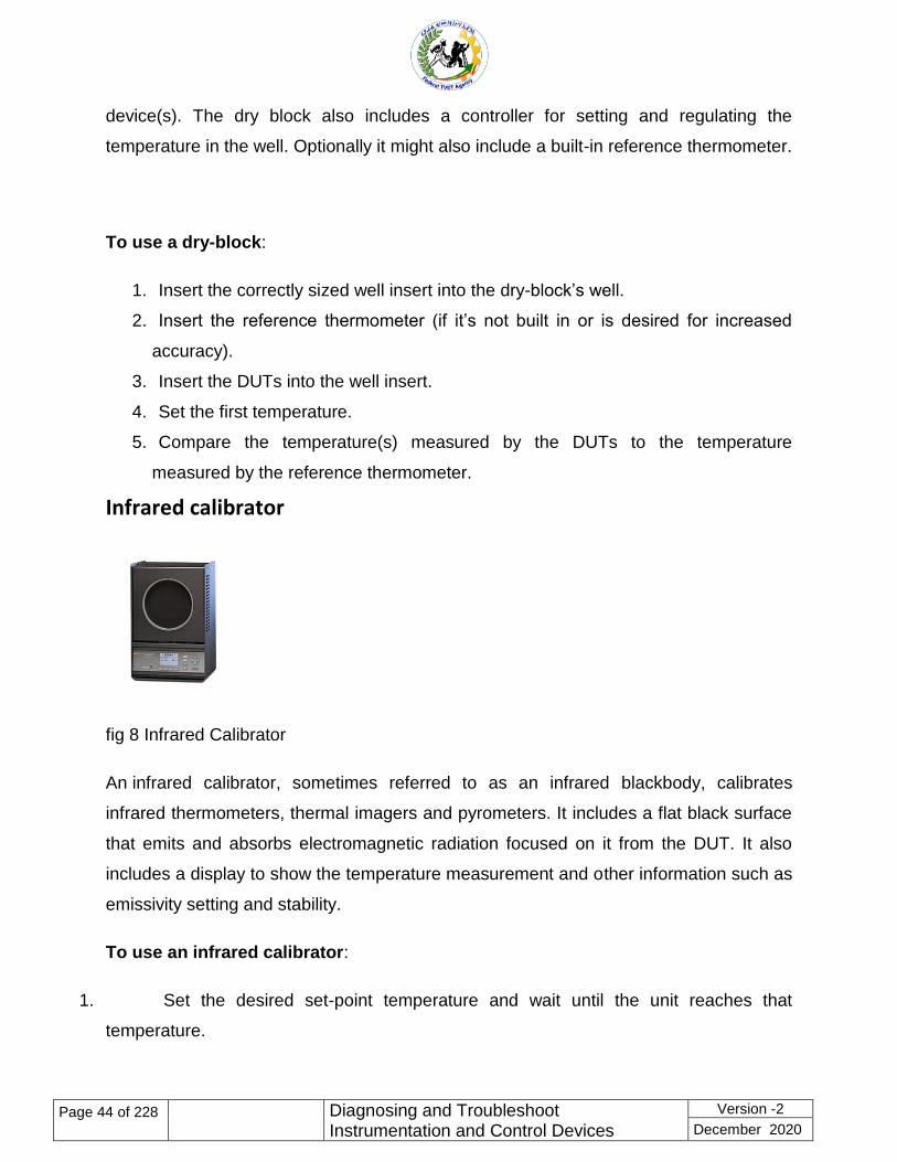
Infrared calibrator
fig 8 Infrared Calibrator
An infrared calibrator, sometimes referred to as an infrared blackbody, calibrates
infrared thermometers, thermal imagers and pyrometers. It includes a flat black surface
that emits and absorbs electromagnetic radiation focused on it from the DUT. It also
includes a display to show the temperature measurement and other information such as
emissivity setting and stability.
To use an infrared calibrator:
1. Set the desired set-point temperature and wait until the unit reaches that
temperature.
Page 45
Page 45 of 228
Diagnosing and Troubleshoot Instrumentation and Control Devices
Version -2
December 2020
2. Turn on the DUT and aim the beam toward the center of the heated blackbody
surface.
3. Record the measurement.
Pressure calibrator
A pressure calibrator calibrates devices that measure pressure. Common devices, or
workload, that can be calibrated include:
Analog and digital pressure gauges
Digital test gauges
Pressure transducers
Barometers
Relief valves
Dial gauges
Pressure switches
Pressure sensors
Pressure transmitters
Down hole tools
Relief valves
Pressure calibration instruments require a pressure supply, which typically comes from
compressed gas (pneumatic) or compressed fluid (hydraulic). The pressure supply can
be external (for example, it comes from a tank full of gas) or internal (such as a pump
built into the instrument).
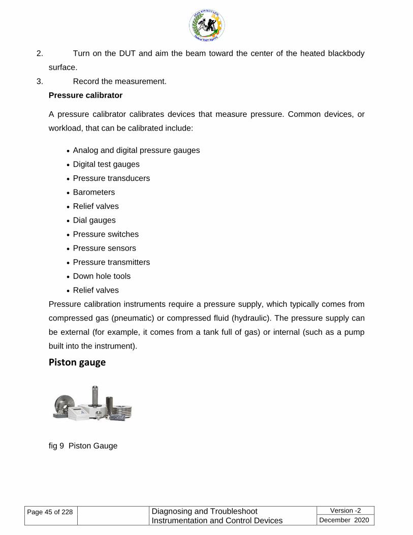
Piston gauge
fig 9 Piston Gauge
Page 46
Page 46 of 228
Diagnosing and Troubleshoot Instrumentation and Control Devices
Version -2
December 2020
A piston gauge is also referred to as a pressure balance or a deadweight gauge.
Workload (or things that can be calibrated) for this type of calibration instrument
includes:
Pressure controllers
Deadweight testers
Other piston gauges
Portable and handheld pressure standards
High accuracy barometers
Air data test sets
A piston gauge typically includes:
A piston-cylinder and platform
Calibrated masses (weights) to mount on the piston
Controller to set and adjust pressure
Bell jar cover (in some cases)
Various accessories (O-rings, valves, etc.)
External pressure source
A piston gauge operates by balancing pressure from a weight mass, subjected to
acceleration due to gravity, against a vertically mounted piston rotating in a cylinder. A
technician loads a specific weight (mass) onto the piston, applies pressure to raise the
piston above the piston gauge housing until it’s ―floating‖ and rotates the piston. When
the force applied by the pressure and the force applied by the mass are in equilibrium,
the piston ―floats‖. At this point, the piston gauge is ready to make a measurement.
Deadweight tester
Page 47
Page 47 of 228
Diagnosing and Troubleshoot Instrumentation and Control Devices
Version -2
December 2020
fig 10Deadweight Tester
A deadweight tester uses calibrated weights (masses) to apply pressure to a device
under test (DUT) so that its pressure can be measured.
Deadweight testers calibrate a wide variety of pressure gauges and sensors. Parts of a
deadweight tester typically include:
Piston cylinder and platform
Calibrated masses (weights)
A reservoir for holding the pressure source (gas or liquid)
A pump to generate and adjust the pressure
To perform a calibration with a deadweight tester:
1. Set the mass (weight) on the piston.
2. Increase the pressure under the piston until it floats while being rotated.
Determine the reference pressure from the calibrator due to the environmental
data and calibration data.
3. When the pressure stabilizes, take the measurement.
Pressure controller/calibrator
fig 11 Pressure Controller/Calibrator
A pressure controller/calibrator measures and controls the pressure in a test system.
Most modern controllers reach stable pressure quickly and can cover a wide range of
pressures. They are so accurate they can even replace piston gauges in some
applications.
Pressure controllers calibrate workload (devices under test - DUTs) that includes:
Page 48
Page 48 of 228
Diagnosing and Troubleshoot Instrumentation and Control Devices
Version -2
December 2020
Digital test gauges
Pressure transmitters
Pressure transducers
Dial gauges
Pressure switches
Portable calibrators
Barometers
Downhole tools
Many pressure controllers can be automated with calibration software and support
remote communication through RS-232, GPIB, USB, and/or Ethernet ports. They can
sometimes be rack-mounted. These features make them popular in manufacturing
applications.
A pressure controller typically includes:
Devices to measure and control pressure
Display
Keys and/or dials to enter and adjust data
Port to which pressure can be applied
To use a pressure controller:
1. Connect it to a pressure supply.
2. Connect the DUT to a test port.
3. Use the instrument’s controls to adjust the pressure.
4. Take and record the measurement.
5. Move to the next test point and repeat the process.
See the benefits of a modular pressure controller in this video.
Pressure comparator
Page 49
Page 49 of 228
Diagnosing and Troubleshoot Instrumentation and Control Devices
Version -2
December 2020
fig 11 Pressure Comparator
A pressure comparator supplies a precisely controlled pressure to both a reference
gauge and DUT. Pressure comparators include mechanical components that generate
and fine-tune pressure measurements. A comparator also includes a test port for a
reference gauge and a second port for the DUT. A hydraulic comparator includes a fluid
reservoir and a screw press for generating the pressure. A pneumatic comparator
includes a pump for generating the pressure and a vent valve for releasing the
pressure.
Pressure comparators calibrate devices or workload that includes:
Dial gauges
Pressure transmitters
Pressure switches
Relief valves
To use a pressure comparator:
1. Connect the reference gauge and the DUT.
2. Use a pump to apply pressure.
3. Use a screw press to adjust the pressure.
4. Take and record the measurement.
5. Move to the next test point and repeat the process.
Portable handheld pressure calibrator
Page 50
Page 50 of 228
Diagnosing and Troubleshoot Instrumentation and Control Devices
Version -2
December 2020
fig 12 Portable Handheld Pressure Calibrator
A portable handheld pressure calibrator is typically small enough to hold in one hand,
and it is often rugged enough to use in industrial environments. They are typically less
accurate than bench pressure calibrators like those discussed above.
Portable pressure calibrators calibrate:
Dial gauges
Pressure transmitters
Pressure switches
Relief valves
A portable pressure calibrator typically consists of a display, ports for connecting test
leads, and buttons to set and adjust the pressure parameters. As with all pressure
calibrators, a pressure source is also required. This could be an external source or a
built-in pump. These devices are often used in industrial environments and might be
battery-powered, lightweight, and include a sturdy case.
To perform a test with a portable pressure calibrator:
1. Connect the instrument to the device under test (DUT).
2. Apply pressure to the DUT.
3. Record the measurement displayed on the instrument.
4. Move to the next test point and repeat the process.
Air data calibrator
Page 51
Page 51 of 228
Diagnosing and Troubleshoot Instrumentation and Control Devices
Version -2
December 2020
fig 4.12 Air Data Calibrator
Air data calibrators calibrate avionics instrumentations such as:
Altimeters
Airspeed indicators
Rate of climb meters
Mach meters
Air data computers
Engine-based control systems
These instruments typically include keys and/or a dial and a display for setting and
viewing pressures, plus electronics for measuring and controlling pressure. It might also
include connectors for automating the calibration with calibration software.
To use an air data calibrator:
1. Set the appropriate unit of pressure.
2. Set the instrument to control the pressure.
3. When pressure is stabilized, set the instrument to make a measurement.
4. Make and record the measurement.
5. Move to the next test point and repeat the process.
Electrical calibrator
Page 52
Page 52 of 228
Diagnosing and Troubleshoot Instrumentation and Control Devices
Version -2
December 2020
fig 14 Electrical Calibrator
An electrical or electronic calibrator calibrates electronic instruments. Electronic
instruments typically measure some combination of voltage, current, resistance,
inductance, capacitance, time and frequency. They might also include electrical power
and phase.
An electrical calibrator typically provides output signals that are read by the DUT. It
might also make precision measurements.
Typical instruments or workload that can be calibrated by an electrical calibrator
includes:
Digital multimeters
Current clamps and clamp meters
Thermocouples and RTDs
Process calibrators
Data loggers
Strip and chart recorders
Wattmeters
Power harmonics analyzers
Panel meters
Graphical multimeters
Some calibration instruments can be purchased with options to handle additional
workload like oscilloscopes and power quality analyzers.
An electrical calibrator typically includes input and output ports, keys and/or a dial to
input parameters and make menu selections, and a display. It might include connectors
for remote or automated operation. Some of these instruments can be partially or fully
automated with software.
To use an electrical calibrator:
1. Connect the instrument to the device under test (DUT).
Page 53
Page 53 of 228
Diagnosing and Troubleshoot Instrumentation and Control Devices
Version -2
December 2020
2. Set the DUT to the appropriate parameter (for example, 10 volts dc).
3. Set the instrument to output the appropriate source for that parameter.
4. Press a Start or Enter key on the instrument to begin the test.
5. Record the result.
Many electrical calibrators are laboratory instruments that sit on a bench and plug into a
wall. For fieldwork, portable electrical or current instruments can be used, although they
are typically not as accurate as the bench instruments.
fig 15 RF Calibrator
A radio frequency, or RF, calibrator
Calibrates radio frequency in instruments such as:
Spectrum analyzers
RF power sensors
Modulation meters and analyzers
Measurement receivers
Frequency counters
RF attenuators and components
High-frequency oscilloscopes
RF calibration can be complex because of the number of tests required to calibrate this
type of workload. Therefore, a system comprised of multiple instruments is typically
required. Instruments found in a typical RF calibration system include:
Signal generators
Level generator
Page 54
Page 54 of 228
Diagnosing and Troubleshoot Instrumentation and Control Devices
Version -2
December 2020
Function generator
Power meters
Measuring receiver
Spectrum analyzer
RF and microwave counters
Network analyzer
Audio analyzer
Oscilloscope
Digital multimeter
These instruments might be individual pieces of equipment; however, in some cases,
the functionality of multiple instruments might be combined in a single calibration
instrument. Consolidating functions helps to reduce the possibility of error.
To use an RF calibrator, you connect it to the DUT and generate a series of signals
such as RF output, leveled sine, modulated output, sweep output, frequency, power and
more. Choosing the right kinds of cables is important to avoid excessive attenuation
(reduction of the signal) and other unwanted effects. You might need to apply RF
correction factors to account for measurement issues such as adapter insertion loss or
splitter tracking errors.
Humidity Calibrator
fig 16 Humidity Calibrator
Page 55
Page 55 of 228
Diagnosing and Troubleshoot Instrumentation and Control Devices
Version -2
December 2020
A humidity calibrator generates humidity to test sensors such as humidity probes that
make critical measurements to protect against spoilage in industries such as
pharmaceuticals, medical devices, semiconductors, chemicals, and food production.
A humidity calibrator typically includes:
Chamber for holding the device under test (DUT)
Display to show temperature and humidity setpoints and actual measurements
Mixing insert to circulate air for temperature and humidity uniformity
Container for holding water
Desiccant cartridge to provide a source of low humidity
To use a humidity calibrator, follow these general steps:
1. Fill the designated container with distilled water.
2. Place the DUT(s) into the calibration chamber.
3. Set temperature and humidity.
4. Make sure the temperature and humidity are stable.
5. Make and record the measurements.
6. Do lower-relative humidity calibrations first and ramp up to the higher-humidity
levels on each subsequent step.
See a product demonstration of the Fluke 5128A Humidity Generator in this video.
Flow calibrator
fig 17 Flow Calibrator
Page 56
Page 56 of 228
Diagnosing and Troubleshoot Instrumentation and Control Devices
Version -2
December 2020
A flow calibrator calibrates devices that sense and control flow. Typical devices under
test (DUTs) include flow meters and flow controllers used in process control
applications, environmental quality/monitoring, medical/breathing systems, leak testing,
and National Measurement Institutes.
These instruments may test gas flow or liquid flow. When testing liquid flow, the liquid
can remain in an open container, but when testing gas flow, the gas must be contained.
A flow calibrator typically includes:
A user interface comprised of a display and keypad
Flow elements that make the actual flow measurements
Various connectors
To use a flow calibrator:
Make a leak-free plumbing connection between the DUT and the instrument.
Pass the gas or liquid media through both devices, maintaining a steady-state
flow.
Compare the outputs of the instrument and the DUT over the same time period.
Some flow calibration instruments can be automated with calibration software.
Automation enables you to take multiple readings at the same time from both the DUT
and the instrument.
Process calibrator
The term ―process calibrator‖ refers to a category of instruments used in process
industries. A process industry is one that produces a product using ingredients in a
batch, rather than manufactured with parts as an individual product. Examples of
process industries include food and beverage, chemicals, pharmaceuticals, and
petroleum.
Milliamp (mA) loop calibrators. This category of tools might perform
calibrations, troubleshoot control valves, or both.
Page 57
Page 57 of 228
Diagnosing and Troubleshoot Instrumentation and Control Devices
Version -2
December 2020
Documenting process calibrators. As the name implies, these tools perform
calibrations and also document the results. This category of instrument typically sources
and measures a wide variety of parameters that could include volts, frequency, ohms,
thermocouples, and more.
Handheld temperature calibrators. As the name states, these are handheld
tools that source and measure temperature. They typically simulate outputs from
temperature sensors and are used with a reference probe whose measurements are
compared with those of the sensor under test. Learn more at our Temperature
Calibrator page.
Multifunction process calibrators. These instruments are designed for process
professionals who work with a varied workload and need to calibrate various test and
measurement instruments, so they require a wide variety of sourcing and measurement
capabilities.
Pressure gauge calibrators. This type of instrument typically includes a reference
pressure gauge that is used as a reference to compare against the gauge being tested.
fig 17 Process Calibrators
Who uses calibrators
Calibration professionals are people who care about making accurate measurements
and maintaining measurement quality to one degree or another. A variety of different job
titles could be considered for people who perform calibrations.
Metrologist
Metrologists work in measurement science. A metrologist’s responsibilities might
include:
Page 58
Page 58 of 228
Diagnosing and Troubleshoot Instrumentation and Control Devices
Version -2
December 2020
Maintaining traceability of his company’s instruments, measurements, and
calibrations
Maintaining calibration laboratory accreditation
Developing and evaluating calibration systems
Identifying and quantifying error sources that contribute to the uncertainty of
results, to determine the reliability of measurement processes
Redesigning or adjusting measurement capabilities to minimize errors
Developing calibration methods
Directing engineering, quality and laboratory personnel in measurement
standards
You might find a metrologist in a calibration laboratory in a manufacturing company, or
in a third-party calibration lab that specializes in performing calibrations on behalf of
others. Governments typically have calibration laboratories staffed with metrologists.
Calibration engineer
This field of engineering supports activities like these:
Analyzing inspection, measuring, and test equipment to determine the calibration
requirements
Determining the functions to be tested and their specifications, the methods to be
used, and the measurement standards required
Preparing and testing new calibration procedures.
Setting appropriate calibration intervals to meet corporate reliability goals
Calibration engineers often work in calibration laboratories or calibration services
companies, but you might also find them in process industries, labs or on the factory
floor.
Calibration technician
A calibration technician performs tasks like these:
Page 59
Page 59 of 228
Diagnosing and Troubleshoot Instrumentation and Control Devices
Version -2
December 2020
Tests, calibrates and repairs instruments and equipment for conformance to
standards
Assists in formulating calibration standards
Uses documentation to plan calibration procedures and determine the required
equipment
Sets up laboratory equipment to test, evaluate and calibrate other instruments
and test equipment
Disassembles instruments and inspects components for defects
Aligns, repairs, replaces component parts and circuitry
Assists engineers in formulating test, calibration, repair and plans to maintain the
accuracy of instruments and equipment
Calibration technicians work in calibration labs, including third-party labs, large in-house
labs and I&E shops.
Laboratory manager
A calibration laboratory manager typically performs these tasks:
Supervises laboratory technicians
May function as a metrologist in addition to being a business manager
Works in an office but can go out to the field if needed
Reviews data for consistency and acts as a dispatcher tech when a need for
reactive maintenance is identified
Responsible for lab throughput, turnaround time and on-time delivery
Lab managers work in calibration laboratories, including third-party labs, large in-house
labs, I&D shops, and government labs.
manufacturing engineer performs:
Production related activities, such as setting up and maintaining a production cell
and equipment
Preventive maintenance
Page 60
Page 60 of 228
Diagnosing and Troubleshoot Instrumentation and Control Devices
Version -2
December 2020
Troubleshooting performance and quality issues
Equipment repair
Calibration
Software development
Safety-related activities
Manufacturing engineers work for small, medium or large manufacturers.
Instrument technician
An instrument tech’s responsibilities might include
Installing, calibrating or maintaining instrumentation for a facility or region
Completing the jobs assigned to him by the maintenance manager or
instrumentation lead at larger companies
Might also be an electrician
Instrument technicians typically work at large process companies (mills,
pharmaceuticals, oil and gas, chemical processing)
How often should a calibrator be used
Another way to ask this question is, how often should you calibrate? The answer
depends on the nature of your workload (the types of things you calibrate and how
often), the quality standards you comply with, your requirements for accuracy, and your
specific applications. Most of the instruments you calibrate will have calibration intervals
recommended by their manufacturers. You might also decide to perform calibrations in
a regular cadence, such as annually or biannually. If you frequently make critical
measurements, you might want to calibrate even more often – even monthly.
Other factors that might influence how often you calibrate:
Your organization is implementing a critical measuring project, such as taking a
plant down for testing. If you work in an industry such as pharmaceutical, regulations
might require you to calibrate before and after the project. Similarly, if your organization
Page 61
Page 61 of 228
Diagnosing and Troubleshoot Instrumentation and Control Devices
Version -2
December 2020
requires highly accurate measurements, you want to ensure that your measurement
standards remain in tolerance.
An instrument is impacted in some way that might affect its performance. For
example, if an instrument is dropped, you might want to calibrate it to make sure it
remains in good working order.
Of course, you will need to calibrate your equipment periodically, and that may mean
taking it out of service while the calibration is being done. If calibrating a calibrator, in
some cases, a modular type of calibrator could remain in service because you can swap
out and calibrate the modules.
Automation of calibrators
Performing calibrations manually can be time consuming and also carries the possibility
of user error. Automating the process can improve throughput significantly while also
ensuring that the calibrations are performed consistently and without error.
Calibrators are typically automated with software. The calibration software includes a
series of step-by-step commands, called procedures that tell the instrument what
signals to output throughout the test. The procedure might also include illustrations that
show a technician how to connect the instrument to the device under test (DUT). If a
calibrator can be automated completely, the technician just connects it to a DUT, runs
the appropriate procedure, and walks away to perform other tasks.
When should you upgrade an old calibrator?
For many calibration professionals, a calibrator just keeps getting better over the years.
That’s because over time the lab learns how the instrument behaves, so there is a
general understanding, plus recorded data, of the instrument’s drift rate, accuracy, and
so forth.
However, no one wants to risk the downtime that results when a calibrator stops
working. Careful planning is necessary to make decisions about the best time and/or
reasons to replace an old calibration instrument.
Page 62
Page 62 of 228
Diagnosing and Troubleshoot Instrumentation and Control Devices
Version -2
December 2020
In planning for a replacement purchase, you’ll want to understand how the old one is
being used and what the risks are if it malfunctions. Mission-critical equipment should
be replaced before a downtime situation occurs.
Here are some reasons you might want to replace an old calibrator:
It’s obsolete or end-of-service, meaning the manufacturer no longer supports it
It’s broken or damaged, and repairs are expensive or not possible
Your workload has grown and/or changed and you need better capability
You want to take advantage of features in newer calibration instruments
You want an instrument that is easier for new technicians to learn to use
You are offered a good deal on a new instrument, such as a trade-in program
Communication tools
A two-way radio is a radio that can both transmit and receive radio waves (a
transceiver), unlike a broadcast receiver which only receives content. It is an audio
(sound) transceiver, a transmitter and receiver in one unit, used for bidirectional person-
to-person voice communication with other users with similar radios. Two-way radios are
available in stationary (base station), mobile (installed in vehicles), and hand-held
portable models. Hand-held two-way radios are often called walkie-talkies, handie-
talkies or hand-helds. Two-way radios are used by groups of geographically separated
people who need to keep in continuous voice communication, such as aircraft pilots and
air traffic controllers, ship captains and harbormasters, emergency services personnel
like firemen, policemen, and ambulance paramedics, taxi and delivery services, soldiers
and military units, fast food and warehouse employees, and radio amateurs.
Page 63
Page 63 of 228
Diagnosing and Troubleshoot Instrumentation and Control Devices
Version -2
December 2020
Fig 18 two way radio
Configuration/programmer
A computer programmer, sometimes called a software developer, a programmer or
more recently a coder (especially in more informal contexts), is a person who creates
computer software. The term computer programmer can refer to a specialist in one area
of computers, or to a generalist who writes code for many kinds of software.
In communications or computer systems, a configuration of a system refers to the
arrangement of each of its functional units, according to their nature, number and chief
characteristics. Often, configuration pertains to the choice of hardware, software,
firmware, and documentation. Along with its architecture, the configuration of a
computer system affects both its function and performance
Configuration Vs programmer
Programming requires an understanding of the problem. For data sharing, the
programmer needs to understand the data sharing devices, the operating system and
communication protocols. For optimal data sharing, the programmer may need an in-
depth knowledge of the device and memory interactions.
Configuration tools guide the programmer through the process using interactive
methods. For data sharing, the configuration tools identify the options available for the
selected target platform. For Poly-Platform, the platform specifics are pre-configured
defaults which enable the programmer to quickly have the application running on the
target.
Page 64
Page 64 of 228
Diagnosing and Troubleshoot Instrumentation and Control Devices
Version -2
December 2020
Self-Check -4 Written Test
Directions: Answer all the questions listed below. Use the Answer sheet provided in
the next page:
I. Answer the following question as directed bellow each contain (2%)
1. _______ is an instrument used as a reference (also called a standard),
whose measurements are compared with the measurements of another
instrument of lesser accuracy (called the device under test).
2. Sometimes an instrument like a digital multimeter is used as a calibrator
(True, False)
Page 65
Page 65 of 228
Diagnosing and Troubleshoot Instrumentation and Control Devices
Version -2
December 2020
3. __________used to confirm whether a device under test (DUT) is operating
within the measurement range specified by its manufacturer.
4. Write General steps for using a calibrator:
5. Define traceability
6. Without measurement uncertainty, measurement traceability does not
exist.(True, False)
7. Calibration helps to ensure correct and uniform measurements and that is why
calibration is important(True, False)
8. _____________calibrates devices that measure temperature.
9. _____________are sensors comprised of two wires made from different
metals, connected to form a junction.
10. ___________ is an enclosure filled with fluid that maintains a uniform,
constant temperature for calibrating a wide variety of sensors that require
immersion into a stable temperature source.
11. ________________instruments require a pressure supply, which typically
comes from compressed gas (pneumatic) or compressed fluid (hydraulic).
12. _______________ uses calibrated weights (masses) to apply pressure to a
device under test (DUT) so that its pressure can be measured.
13. _____________measures and controls the pressure in a test system
14. Who uses calibrators?
a) Mythologist
b) Calibration engineer
c) Calibration technician
Page 66
Page 66 of 228
Diagnosing and Troubleshoot Instrumentation and Control Devices
Version -2
December 2020
d) Laboratory manager
e) Manufacturing engineer
f) All
Answer the following question!
Note: Satisfactory rating 3 and 5 points Unsatisfactory below 3 and 5 points
You can ask you teacher for the copy of the correct answers.
Answer Sheet
Name: _________________________ Date: _______________
Information Sheet 5. Consulting appropriate personnel to coordinated work
5.1 Consulting appropriate personnel to coordinated work
Introduction
A consultant is engaged to fulfill a brief in terms of helping to find solutions to specific
issues but the ways in which that is to be done generally falls to the consultant to
decide, within constraints such as budget and resources agreed with the client.
5.1.1 Common types of consultation
Score = ___________
Rating: ____________
Page 67
Page 67 of 228
Diagnosing and Troubleshoot Instrumentation and Control Devices
Version -2
December 2020
In the business, and as of recently the private sphere, the most commonly found
consultants are:
Strategy Consultants working on the development of and improvements to
organizational strategy alongside Senior Management in many industries.
Human Resources or HR Consultants who provide expertise around
employment practice and people management.
Internet Consultants who are specialists in business use of the internet and
keep themselves up-to-date with new and changed capabilities offered by the
web. Ideally internet consultants also have practical experience and expertise in
management skills such as strategic planning, change, projects, processes,
training, team-working and customer satisfaction.
Process Consultants who are specialists in the design or improvement of
operational processes and can be specific to the industry or sector.
Public Relations or PR Consultants dealing specifically with Public Relations
matters external to the client organization and often engaged on a semi-
permanent basis by larger organizations to provide input and guidance.
Performance Consultants who focus on the execution of an intuitive or overall
performance of their client.
Immigration Consultant who helps through legal procedure of immigration from
one country to other country.
Information Technology Consultants in many disciplines such as Computer
Hardware, Software Engineering or Networks.
Marketing Consultants who are generally called upon to advice around areas of
product development and related marketing matters.
Interim Managers as mentioned above may be independent consultants who act
as interim executives with decision-making power under corporate policies or
statutes. They may sit on specially constituted boards or committees.
5.1.2 Electronic consultation
E-Consultation
Page 68
Page 68 of 228
Diagnosing and Troubleshoot Instrumentation and Control Devices
Version -2
December 2020
Technology is having a major impact on the consultation arena. Using technology to
consult is often referred to as Electronic or E-Consultation.
We use E-consultation
E-consultation can give you rapid responses.
E-consultation utilizes software that transfers data directly into databases, saving
time and more because there is no need to manually input data.
E-consultation enables us to explore some of the issues arising from consultation
in more depth through tools such as bulletin boards, online discussion groups
and chat rooms.
Encourages participants into thinking their contribution does make a difference
and is taken seriously by the Council
E-consultation, particularly via the internet can be cheaper than sending out
surveys by post (although e-consultation should be used as part of a range of
methodologies to obtain a representative demographic)
E-consultation can be used to gain feedback on policies, strategies and other
consultation-related documents
Better consultation with Hard to reach groups, i.e. consultation with young
people - a large proportion of who have personal computers, internet access and
mobile phones and do not tend to respond to traditional consultation
techniques.
It is an effective way of engaging people who are housebound.
Page 69
Page 69 of 228
Diagnosing and Troubleshoot Instrumentation and Control Devices
Version -2
December 2020
Self-Check 5 Written Test
Directions: Answer all the questions listed below. Use the Answer sheet provided in
the next page:
I. Answer the following question as directed below each contain (2%)
1. What is the purpose of Electronic or E-Consultation.
2. ___________is engaged to fulfill a brief in terms of helping to find solutions to
specific issues
3. Mention Common types of consultation
4. What is the purpose of E-consultation
. Answer the following question!
Note: Satisfactory rating 3and 4points Unsatisfactory below 3and 4points
You can ask you teacher for the copy of the correct answers.
Page 70
Page 70 of 228
Diagnosing and Troubleshoot Instrumentation and Control Devices
Version -2
December 2020
Answer Sheet
Name: _________________________ Date: _______________
Short Answer Question
Information Sheet 6. Checking instrumentation and Control Systems defects
6.1 Checking instrumentation and Control Systems defects
Basic principles in checking instrumentation and control system defect
To identify a faulty section, follow the guidelines given below, along with a drawing and
a meter:
Check the incoming supply voltages first
Check for voltages at the specific test points in circuit (as per manufacturers test
point data sheet)
Do dead test of circuit for integrity of protection devices and others
In dead test, check for continuity of circuits, as intended, and check for insulation
resistance
If it’s not possible to perform a dead test, connect the supply to the circuit and do
a live test of circuit.
Generally, any electrical circuit can be differentiated in two sections:
Score = ___________
Rating: ____________
Page 71
Page 71 of 228
Diagnosing and Troubleshoot Instrumentation and Control Devices
Version -2
December 2020
Power circuit
Control circuit.
It is always advisable to first check the power circuit. So, if the power circuit
works, as it should, then Fault-finding the control circuit.
Power circuit check list:
Incoming power to circuit and its integrity
Check for correct functioning of protection devices
Check visual cable continuity
Check for any signs of flash or burning smell of devices.
Control circuit check list:
Control circuit power first
Check for proper functioning of relays, timers, and switches
Check visual cable continuity
Check for wire interconnections and terminal connections of circuit
Check logical operational sequence of contactor switching
Check for timer duration settings.
If the above criteria are checked and still the final device is not working, then test the
final device.
Check / inspect instrumentation and control device
There are four grades of inspections defined in IEC 60079 - 17:
1. Continuous supervision:- Defined as frequent attendance, inspection, service, care
and maintenance of the electrical installation by skilled personnel who have the
knowledge and skills to maintain the equipment in accordance with IEC 60079 - 17
Clause 4. 5.
1 Visual inspection: - An inspection that identifies, without use of access equipment or
tools, defects that would be apparent to the eye, such as missing bolts or damaged
cables.
2 Close inspection:-Defined as an inspection that encompasses aspects covered by a
visual inspection and identifies defects that are apparent only by the use of equipment
and tools, such as loose bolts or damaged cable glands.
Page 72
Page 72 of 228
Diagnosing and Troubleshoot Instrumentation and Control Devices
Version -2
December 2020
3 Detailed inspection: - Defined as an inspection that encompasses everything covered
by a close inspection and identifies defects that are only apparent by opening the
enclosure and using tools and test equipment. Detailed inspections can find loose
terminations or incorrect grounds.
These inspections include all equipment located in the hazardous area, and any
protection device located in the safe area. In practice, this is difficult and expensive to
achieve. Some wiring systems may be routed in such a manner as to make inspection
very difficult. Process plants have internal permitting procedures that must be followed
when entering hazardous areas, adding further costs. And there is, of course, the time
required to make inspections, to document work done, and to keep required records.
It’s important to verify that an installation conforms to a detailed equipment list and
circuit diagrams. These and any other documentation listing specific conditions of use
must be made available for the inspector. Often the equipment list has not been
updated with equipment changes as plant modifications are carried out, due to either
failed equipment being replaced with alternatives, or new wiring additions.
If clarification has to be sought regarding the installation and associated documentation,
this adds to the time taken to carry out the inspection. Reducing the number of
equipment items reduces the burden of keeping equipment lists updated, and wireless
instruments are one of best ways to address this issue.
2. Typical issues found during inspections include
Electronic test equipment is used to create signals and capture responses from
electronic devices under test (DUTs). In this way, the proper operation of the DUT can
be proven or faults in the device can be traced. Use of electronic test equipment is
essential to any serious work on electronics systems.
Page 73
Page 73 of 228
Diagnosing and Troubleshoot Instrumentation and Control Devices
Version -2
December 2020
Practical electronics engineering and assembly requires the use of many different kinds
of electronic test equipment ranging from the very simple and inexpensive (such as a
test light consisting of just a light bulb and a test lead) to extremely complex and
sophisticated such as automatic test equipment (ATE). ATE often includes many of
these instruments in real and simulated forms.
Generally, more advanced test gear is necessary when developing circuits and systems
than is needed when doing production testing or when troubleshooting existing
production units in the field.
The addition of a high-speed switching system to a test system’s configuration allows
for faster, more cost-effective testing of multiple devices, and is designed to reduce both
test errors and costs. Designing a test system’s switching configuration requires an
understanding of the signals to be switched and the tests to be performed, as well as
the switching hardware form factors available.
Types of test equipment
The following items are used for basic measurement of voltages, currents, and
components in the circuit under test.
Voltmeter (Measures voltage)
Ohmmeter (Measures resistance)
Ammeter, e.g. Galvanometer or Milliameter (Measures current)
Multimeter e.g., VOM (Volt-Ohm-Milliameter) or DMM (Digital Multimeter)
(Measures all of the above)
RLC Meter e.g., RLC meter or Resistance, Inductance and capacitance meter
(measure RLC values)
The following are used for stimulus of the circuit under test:
Power supplies
Signal generator
Page 74
Page 74 of 228
Diagnosing and Troubleshoot Instrumentation and Control Devices
Version -2
December 2020
Digital pattern generator
Pulse generator
The following analyze the response of the circuit under test:
Oscilloscope (Displays voltage as it changes over time)
Frequency counter (Measures frequency)
Dimensional inspection hand tools are sometimes the best answer when you need to
take measurements. They are both portable and precise, are generally cost-effective,
and they can be used for a broad range of applications.
Types of Dimensional Inspection Hand Tools
1. Calipers - There are several different types of calipers designed to measure
length, depth, internal, and external dimensions. Calipers can also be used to
transfer dimensions from one object to another.
2. Bore gages - Take an internal diameter measurement or compare to a pre-
determined standard.
3. Fixed gages - Used only to compare an object to a standard, fixed gages can
measure attributes such as angle, length, radius, bore size, thickness, and other
parameters.
4. Micrometers - These dimensional inspection hand tools can use mechanical,
digital, laser, dial, or scale technology to precisely measure length, depth,
thickness, diameter, height, roundness, or bore.
5. Protractors - Measure angles with a variable protractor or compare the angle of
an object to a standard with an angle gage.
6. Indicators and comparators - The precision movement of a spindle or probe is
amplified so the results can be displayed digitally or on a dial or column.
7. Air metrology instruments - Thickness, depth, diameter, roundness, taper, and
bore can be measured by calculating changes in pressure or air flow.
8. Ring gages - Typically used as a pass/fail test, ring gages can be threaded,
smooth, or tapered to test the size of pins, threaded studs, and shafts.
9. Length gages - Electronic or mechanical, these devices are used to measure or
compare the length of an object.
Page 75
Page 75 of 228
Diagnosing and Troubleshoot Instrumentation and Control Devices
Version -2
December 2020
10. Thread gages - The spacing, shape, size, and geometry of a thread can be
verified or measured with a thread gage.
Common Control Loops
A sensor is a device that responds to or detects a physical quantity and transmits the
resulting signal to a controller.
Sensors are often used in close-loop control to feed back the output of the system in
order to generate proper control actions.
A transducer is a sensor that converts (transduces) one form of energy to another form,
usually electrical signals.
Defining the Loop
Basic to any discussion of control loops is ―feedback‖ control. In this control, the loop
starts by measuring the process variable (PV). It then compares the PV to the desired
value, that is, the set point (SP), and acts on the difference between SP and PV (error)
using a control algorithm (typically PID). The loop then outputs to the final control
element. The diagrams below indicate that the main elements of the loop are:
transmitter/sensor (for measuring the PV) process controller (with an operator-entered
SP and control algorithm) final control element (valve/actuator and accessories)
Loop checking
Loop Checking means, First we want to check the continuity of cable. Then
whether 24 V DC or 4 – 20 mA DC is coming from DCS or JB want to check. That
is called loop Checking.
After installation of instruments we must check full loop(instrument-junction box-control
room) to ensure that whether the instruments are working properly or not, and whether
is it passing the signal or not, whether is it receiving the signal or not. before we start
the plant we need to check loop. during the loop check we give some known input and
check the corresponding output at other side(control room).if the output
is corresponding to input, the loop is ok.if not means, something fault in between
the loop. for example .if you want to check ON/OFF control valve, during the loop check,
Page 76
Page 76 of 228
Diagnosing and Troubleshoot Instrumentation and Control Devices
Version -2
December 2020
when you give 24 v dc from control room ,the valve must open fully, and when you
give 0 v dc the valve must close.
Loop checking is the final process before the commissioning of the processing system .
loop checking is the process that confirms the components wired correctly and also
helps to ensure that the system is functioning as designed
The loop checking checks the connection between each component in the control loop.
a control loop consists of transmitter, sensor, process controller, final control element
Loop checking & Procedure
Fig 6.1 loop checking
Before start, the loop check include, first list the number of loops, test actions, the
procedure for documenting the check and plan should specify the type and
characterization of signal. For example, differential flow meter generates a signal that
has a square root relationship between flow rate and differential pressure.
A factory acceptance of loop testing can be charted as shown below:
Loop testing procedure:
For loop checking the test to be carried out while there is no electric connection
otherwise, the circuit to be tested should be isolated from the electric supply.
Earthing and Continuity test:
Page 77
Page 77 of 228
Diagnosing and Troubleshoot Instrumentation and Control Devices
Version -2
December 2020
Earth resistance tests are required to confirm that the installed earthing system will
cause the circuit protection devices to operate and maintain the integrity of the cable if
there is a fault between the active parts and the exposed conductive parts.
The resistance from any point of the electric installation should be earthed. The
resistance from the earthing electrode to the point where the main earthing conductor is
connected to the neutral conductor of the supply system shall not exceed 5 ohms.
Ensure that the electricity supply has been disconnected
Connect an insulated copper conductor of suitable length(long lead) to one
terminal of the ohm meter.
Connect a standard length test lead to the other terminal of the ohm metre (
short lead
Connect the two leads together and zero the multimeter or if this is not possible.
Record the resistance of the test lead
Main earth conductor:
Connect the short lead to the earth electrode and measure the earth resistance
of the main earthing conductor
The resistance shall not exceed 5 ohms for the main earthing conductor
Earth continuity test:
Using the long lead and zeroed meter, measure for each circuit, the earth
conductor resistance from the circuit extremity to the switchboard.
To confirm the measured values are less than those values as provided by table
This test is applicable to all circuits, including socket outlets circuit, lighting
circuits and fixed equipment circuits.
Insulation resistance test:
The insulation resistance tests to ensure there is no current flow between conductor and
ground or insulation surface. If there is no current flow the wire could prevent electric
shock hazards, fire hazards and equipment damage.
Test procedure:
Ensure all protective device in the circuit is switched ON.
Page 78
Page 78 of 228
Diagnosing and Troubleshoot Instrumentation and Control Devices
Version -2
December 2020
Set the insulation tester to megaohms
Connect an insulation tester cable to the main earth bar and the other cable to
the active and neutral connected together. Do not perform tests between assets
and neutrals.
Measure the insulation resistance of the total installation, if the resistance is
greater than 1 megaohm then the normal to work.
If resistance is less than 1 megaohm disconnect the appliances. Then test the
circuit separately to ensure that the insulation resistance of both the circuit and
the appliances complies with the following
Not containing a heating element- is not less than1 mega ohm or
Containing a heating element-is not less than 0.01 mega ohm
Polarity test: Polarity tests are carried out to ensure that the correct connection of the
active, neutral and ground conductors to the electrical equipment ensures that the
switches are not installed in neutral conductors.
Test procedure:
Isolate the active conductors by turning the main switch OFF and tagging
Confirm the consumer and sub main cables by simply testing from the point of
distribution board to the main switch board using an ohm meter and long test
loads. Test result= 0 ohms
Confirm the switching of the active conductors using an ohm meter with the long
cable connected to the active conductor on the board and the short wire
connected to the terminals of the switch as follows
Switch ON = 0Ώ for both terminals, Switch OFF = 0Ώ for one terminal and infinite
for the other terminal.
With the MEN link in place, confirm the polarity of the sockets using a 10Ώ
resistor and an ohm meter. Connect the 10Ώ resistor between the active circuit
conductor and the neutral bus, then connect the multimeter cable to the ground
terminal and the second cable to the active terminal. Test the resistance value
for.
Page 79
Page 79 of 228
Diagnosing and Troubleshoot Instrumentation and Control Devices
Version -2
December 2020
Fault loop impedance test: This test is performed to confirm that the impedance value
of the fault loop of each circuit will be low enough to guarantee the operation of the
protection device during a fault.
Test procedure
Energize all circuits
Using the fault loop impedance meter, proceed to the equipment to be tested and
measure the impedance of the ground loop at this point. Repeat for other
elements in the circuit
The measured value must be less than the maximum values as in the Wiring
Rules
If an RCD works during the test, the results of the test can be considered
satisfactory.
Ensure these steps before loop checking
1. Before carrying out the loop test or the sequence test, all related instruments
must be calibrated, this can be seen from the instrument label. The final loop test
will be performed to ensure that the instruments installed are functionally correct.
Each transmitter and switch must not be re calibrated during the loop test, since
all transmitters and switches are installed after the workshop calibration is
completed.
2. When performing tests, two groups will be required, one in the field and other in
the control room. The contractor is required to provide proper communication for
all involved in test verification, i.e. field radios or walkie talkies
3. Associated alarms and trip actions of DCS/PLC and/or board-
mounted instruments shall be checked during the loop test. When particular
loop ties into DCS/PLC system, a technician may be required in the rack
room for troubleshooting
4. When the interlocking inputs and / or outputs are associated with electrical
equipment such as pump motors, compressors and valves, this sequence test
shall be carried out together with the electrical and mechanical discipline to
ensure the protection of the equipment.
Page 80
Page 80 of 228
Diagnosing and Troubleshoot Instrumentation and Control Devices
Version -2
December 2020
Loop Test Procedure
1. Before performing the loop check, check the entire circuit to make sure all cables
are connected. Check the appropriate voltages and instrument air pressure
according to the manufacturer’s recommended requirements.
2. To test the circuit, configure the air and / or electrical supply, as applicable, the
air supply pressure for the control valves and other pneumatic actuators must be
verified and configured correctly according to the specifications.
3. For electronic loops, check the polarities and measure the impedance of the loop
before it is necessary. Before performing the loop test, the DCS must be de-
energized and confirm that all field cables are connected correctly. Then the
DCS.
4. must be energized again. The final circuit test must be performed to ensure that
the installed instrumentation is functionally correct. Each transmitter and switch
must not be recalibrated during the loop test, since all transmitters and switches
are installed after workshop calibration
5. If a transmitter exists in a loop, the output signals equivalent to 0%, 50% and
100% of the range of the instrument will be generated in manual mode
(dummysignals) to verify the function of the loop, such as variable zero variation
of the transmitters or by connecting the standard DC current generator or the
retaining nozzle and the fin in the pilot of the pneumatic transducers.
6. Connect a known precision source to the primary field transmitter. The
assimilation of the measured variable is applied to the transmitter for reading at
zero, half scale and full scale, according to the instructions recommended by the
manufacturer. Note in the PLC system that the indication is shown as simulated.
Also note on the MMI screens (Man Machine Interface) on the PC. You must
indicate the appropriate actions in Screen and Alarm Screen
7. If there is a local controller mounted in a loop, the signal to verify the operation
of the valve will be generated manually using the manual operation device in the
controller before the automatic operation check. An automatic operation check
will be performed by changing the set point of the controller.
Page 81
Page 81 of 228
Diagnosing and Troubleshoot Instrumentation and Control Devices
Version -2
December 2020
8. Control loop: Place the controller in manual mode and simulate the signal of the
process variable from 0%, 25%, 50%, 75% and 100% of the scale and note on
the monitor that the process variable indication shows signals assimilated.
Return the process variable to 0%, place the controller in automatic mode, set
P.B. 100%, restart the time and derived to Minimum adjustment with 50% set
point and make sure the controller is an indirect action. Simulate the process
variable signal 0%, 25%, 50%, 75% and 100%, observe and record all the
findings
9. For pressure switches and level interrupters, their contact must be made
manually and / or interrupted to guarantee the corresponding responses of the
instrument.
For thermocouple loops, check the burn characteristics by disconnecting the cables,
and confirm that the polarity of the thermocouple extension leads is maintained when
they are reconnected. To assist in the identification of the thermocouple extension
cables, the following guidance is provided.
a) The negative extension cables are always colored in red as in the PER ANSI
C96.1.
b) For the K-type thermocouple (Chromel / alumel), the negative cable is slightly
magnetic. It has a lower resistance in ohms / feet for the same size cable.
c) For R type thermocouple (copper alloy / nickel copper), the negative wires are
softer than the positive wire.11.For the loops of the resistance temperature
detector (RTD), check the function of all the instruments and control valves in the
circuit by connecting the resistor approximately 120 ohm in the terminal heads,
and visually verify the correct connections when closing the terminal heads.
Page 82
Page 82 of 228
Diagnosing and Troubleshoot Instrumentation and Control Devices
Version -2
December 2020
Fig 20 block diagram of feed back loop
Control Valves Loop Checks Procedure
1. For FF device commission FF segment prior to loop testing 12 by measuring
resistance and DC voltage of segment conductor if all devices are connected
otherwise only resistance will be recorded and voltage will be measured after all
devices are connected and compare the results with FF segment checkout form.
2. Check and verify the DCS configuration for applicable points. Reference
drawings are to be P&ID and ISS.
3. If any logic / interlocking are involved in applicable loop. Energize the solenoid
valve by forcing the applicable ESD points on functional logic and same
procedure to be carried out for DCS logic.
4. If instrument air supply is not available then, dry and clean air or nitrogen shall be
used.
5. Apply the command from DCS for 0%, 25%, 50%, 75%, 100% and monitor the
response of the valve from the field.
6. Verify the corresponding valve position.
7. Verify the controller action.
8. Verify the control valve action on increase signal.
9. Verify the control valve action on air supply failure.
10. Verify the control valve max / min travel stopper setting if applicable.
11. Check the hand wheel manual operation / function if applicable. Auto/ manual
calibration is applicable.
12. Normally control valve loop test should be performed after completion of the
external air supply piping works. In some cases when required, loop test can be
executed without the internal air supply piping.
13. In case of air piping is not installed and tested then this exception item to be
mentioned in the loop test exception log sheet prior to signing the loop folder.
14. Loop will be installed only and signed after the clearance of the punch list.
Loop checking procedure of Instruments
Page 83
Page 83 of 228
Diagnosing and Troubleshoot Instrumentation and Control Devices
Version -2
December 2020
This article is about the loop checking procedure of all instruments like flow transmitter,
valves, vibration, DCS loop, switchgear loop and remaining pressure and level types
instruments.
List of tools and equipment in loop checking
Tools and equipment needed should be in good condition and must be checked by
instrument supervisor prior to use. Calibration equipment shall comply with the
saudiaramco standards requirements and provided with calibration certificate to support
the readings of the calibrating equipment these includes but not
limited to:
HART Communicator
Dead Weight Tester
Air Compressor
MC5 FF Multifunction Calibrator
Test Gauges with Ranges per Specification
Absolute Pressure Gauge
Portable 120Vac, 60Hz Gasoline Powered Generator
Pulse/Frequency Generator
DC Power Supply Regulated 24Vdc Variable
Nitrogen Tank w/ High Pressure Regulator
Thermo Bath
Hydrostatic Test Pump
Set of Precision Weights
Digital Thermometer
Glass Thermometer
Potentiometer
Portable Pressure Calibrator (DRUCK)
Page 84
Page 84 of 228
Diagnosing and Troubleshoot Instrumentation and Control Devices
Version -2
December 2020
Process Calibrator
Advanced Temperature Calibrator
RTD Conversion Chart
Circuit Tester
Decade Resistance Box
Digital Manometer (Mercury or Water Manometer)
Mercury and Water Manometer
Hand Pump
Hygrometer (Humidity Tester)
Air Regulator
Pneumatic Comparator
Vacuum Pump
Oscilloscope
Radio Communication Equipment (intrinsically safe as per approved)
Multi meter
Test Bench with clean, dry and oil free instrument air
Set of Tools, Hose & Fittings
Stop Watch
Millivolt/Temperature conversion chart
TK-3 (for checking of vibration element)
Spirit Level
BEAMEX MC5 Calibrator
All tools utilized in a classified area should be intrinsically safe and suitable for
hazardous area
Page 85
Page 85 of 228
Diagnosing and Troubleshoot Instrumentation and Control Devices
Version -2
December 2020
Operation title: - loop checking for on / off valves loops
Purpose To acquire the trainees with loop checking for on / off valves loops
Equipment
,tools and
materials
Supplies and equipment needed or useful for diagnosing and
troubleshoot instrumentation and control Devices
include these:
screw driver
Diagonal side cutter
Pliers
Knife
drill
shaper
cutter
Soldering iron
WRENCH
Digital Multi-tester
calibrator
oscilloscope
signal generator
various instrument and control device
configuration or programmer
DCS / ESD configuration
On/Off valve
Conditions or All tools, equipment’s and materials should be available on time
Page 86
Page 86 of 228
Diagnosing and Troubleshoot Instrumentation and Control Devices
Version -2
December 2020
situations for
the operations
when required.
Appropriate material, working area/ workshop for loop checking on /
off valves loops
Procedures 1. Apply OH &S PPE
2. Check and verify the DCS / ESD configuration for applicable
points.
3. If any ESD logic / interlocking are involved in applicable loop to
energized solenoid valve, should be prepared ESD points on
functional logic and same procedure to be carried out for DCS
logic.
4. If instrument air supply is not available then connect nitrogen
cylinder. In big size of valve cases, big volume of
nitrogen will be required then in that case on/off valves function
test will be executed upon air supply availability.
5. Apply the command from DCS / field for open and close as
applicable.
6. Verifying the corresponding valves position in DCS and field.
7. Verify the partial stroke function test of ―ZV‖.
8. Verify the valve action on air supply failure.
9. Check the hand wheel / hand jack manual operation / function as
applicable.
10. Normally On/Off valve loop test should be performed after
completion of the external air supply piping works. In some cases
when required, loop test can be executed without air.
11. In case of air piping is not installed and tested then this exception
item to be mentioned in the loop test exception log sheet prior to
Page 87
Page 87 of 228
Diagnosing and Troubleshoot Instrumentation and Control Devices
Version -2
December 2020
signing the loop folder.
12. Loop will be initiated only and signed after the clearance of the
punch list.
13. Valve response time shall be recorded in loop record sheet
Precautions Care should be taken while connecting with electric power,
assembling, fitting and adjusting instrumentation and control
devices
Preparing materials, tools and equipment are according to
inseminator command.
Quality criteria Did personal protective equipment worn diagnosing and
troubleshoot instrumentation and control Devices
Did trainees fitting and adjusting the component of the machine
proper without leakage
Checks the circuit safely using proper instrument
Mounts devices according to the given drawing
Installs electrical wiring according to the job requirements
Loop checking for on / off valves loops
LAP Test Practical Demonstration
Name: _____________________________ Date: ________________
Time started: ________________________ Time finished: ________________
Instructions:
1. You are required to perform any of the following:
1.1. Diagnosing and troubleshoot instrumentation and Control Devices
1.2. Prepare equipment and material for diagnosing and troubleshoot instrumentation
and Control Devices
Page 88
Page 88 of 228
Diagnosing and Troubleshoot Instrumentation and Control Devices
Version -2
December 2020
2. Request your Trainer for evaluation and feedback
Operation title: loop checking Conventional Control Valves Loops
Purpose To acquire the trainees with loop checking Conventional Control
Valves Loops
Equipment
,tools and
materials
Supplies and equipment needed or loop checking Conventional
Control Valves Loops
include these:
screw driver
Diagonal side cutter
Pliers
Knife
drill
shaper
cutter
Soldering iron
wrench
Digital Multi-tester
calibrator
oscilloscope
Page 89
Page 89 of 228
Diagnosing and Troubleshoot Instrumentation and Control Devices
Version -2
December 2020
signal generator
various instrument and control device
configuration or programmer
communication equipment(2=way radio cell phone)
DCS / ESD configuration
Conventional Control Valves Loops
Conditions or
situations for
the operations
All tools, equipment’s and materials should be available on time
when required.
Appropriate material, working area/ workshop for loop checking
Conventional Control Valves Loops
Procedures
1. Apply OH&S PPE
2. Check and verify the DCS configuration for applicable points.
Reference drawings are to be P&ID and ISS.
3. If any logic / interlocking are involved in applicable loop. Energize
the solenoid valve by forcing the applicable ESD points on
functional logic and same procedure to be carried out for DCS
logic.
4. If instrument air supply is not available then, dry and clean air or
nitrogen shall be used.
5. Apply the command from DCS for 0%, 25%, 50%, 75%, 100%
Page 90
Page 90 of 228
Diagnosing and Troubleshoot Instrumentation and Control Devices
Version -2
December 2020
and monitor the response of the valve from the field.
6. Verify the corresponding valve position.
• Verify the controller action.
Verify the control valve action on increase signal.
Verify the control valve action on air supply failure.
• Verify the control valve max / min travel stopper setting if
applicable.
• Check the hand wheel manual operation / function if applicable.
Auto/ manual calibration is applicable.
• Normally control valve loop test should be performed after
completion of the external air supply piping works. In some
cases when required, loop test can be executed without the
internal air supply piping.
• In case of air piping is not installed and tested then this exception
item to be mentioned in the loop test exception log sheet prior to
signing the loop folder.
• Loop will be installed only and signed after the clearance of the
punch list.
Precautions Care should be taken while connecting with electric power,
assembling, fitting and adjusting instrumentation and control
devices
Preparing materials, tools and equipment are according to
inseminator command.
Quality criteria Did personal protective equipment worn diagnosing and
troubleshoot instrumentation and control Devices
Did trainees fitting and adjusting the component of the machine
Page 91
Page 91 of 228
Diagnosing and Troubleshoot Instrumentation and Control Devices
Version -2
December 2020
proper without leakage
Checks the circuit safely using proper instrument
Mounts devices according to the given drawing
Installs electrical wiring according to the job requirements
Checking Conventional Control Valves Loops
LAP Test Practical Demonstration
Name: _____________________________ Date: ________________
Time started: ________________________ Time finished: ________________
Instructions:
1. You are required to perform any of the following:
1.1. Diagnosing and troubleshoot instrumentation and Control Devices
1.2. Prepare equipment and material for diagnosing and troubleshoot instrumentation
and Control Devices
2. Request your Trainer for evaluation and feedback
Operation title: loop checking procedure thermocouple / temperature transmitter
loops
Page 92
Page 92 of 228
Diagnosing and Troubleshoot Instrumentation and Control Devices
Version -2
December 2020
Purpose To acquire the trainees with loop checking procedure thermocouple /
temperature transmitter loops
Equipment
,tools and
materials
Supplies and equipment needed or useful for loop checking
procedure thermocouple / temperature transmitter loops
include these:
screw driver
Diagonal side cutter
Pliers
Knife
drill
shaper
cutter
Soldering iron
wrench
Digital Multi-tester
calibrator
oscilloscope
signal generator
various instrument and control device
configuration or programmer
communication equipment(2=way radio cell phone)
DCS / ESD configuration
On/Off valve
Conditions or
situations for
the operations
All tools, equipment’s and materials should be available on time
when required.
Appropriate material, working area/ workshop to diagnosing and
troubleshoot instrumentation and control devices
Page 93
Page 93 of 228
Diagnosing and Troubleshoot Instrumentation and Control Devices
Version -2
December 2020
Procedures 1. Apply OH&S PPE
2. Check and verify the DCS configuration for applicable points.
• Simulate millivolt equivalent to the 0%, 25%, 50%, 75% and 100%
of the transmitter / DCS range, by using ―mv‖ source (simulator) at
the thermocouple terminal head.
• Verify the corresponding reading in the DCS / integral indicator of
transmitter and remote indicator if applicable.
• Alarm functions (in DCS) to be checked by simulating / varying the
required signals.
• Normalize all the connections prior to closing the terminal and
confirm ambient temperature at integral indicator of temperature
transmitter and at remote indicator if applicable to DCS.
Precautions Care should be taken while connecting with electric power,
assembling, fitting and adjusting instrumentation and control
devices
Preparing materials, tools and equipment are according to
inseminator command.
Quality criteria Did personal protective equipment worn
Did trainees fitting and adjusting the component of the machine
proper without leakage
Checks the circuit safely using proper instrument
Mounts devices according to the given drawing
Installs electrical wiring according to the job requirements
Page 94
Page 94 of 228
Diagnosing and Troubleshoot Instrumentation and Control Devices
Version -2
December 2020
Loop checking procedure thermocouple / temperature transmitter loops
LAP Test Practical Demonstration
Name: _____________________________ Date: ________________
Time started: ________________________ Time finished: ________________
Instructions:
1. You are required to perform any of the following:
1.1. loop checking procedure thermocouple / temperature transmitter loops
1.2. Prepare equipment and material for loop checking procedure thermocouple /
temperature transmitter loops
2. Request your trainer for evaluation and feedback
Identify Power Supply and CPU LED status indicators
Match processor LEDs with the status LEDs located in troubleshooting tables
Once the status LEDs are matched to the appropriate table, simply
move across the table identifying error description and probable causes
Follow the recommended action steps for each probable cause until the cause is
identified
Page 95
Page 95 of 228
Diagnosing and Troubleshoot Instrumentation and Control Devices
Version -2
December 2020
Operation title:-loop checking procedure RTD /temperature transmitter loops
Purpose To acquire the trainees with loop checking procedure RTD /temperature
transmitter loops
Equipment
,tools and
materials
Supplies and equipment needed or useful for loop checking
procedure RTD /temperature transmitter loops
include these:
screw driver
Diagonal side cutter
Pliers
Knife
drill
cutter
Soldering iron
wrench
Digital Multi-tester
calibrator
oscilloscope
signal generator
various instrument and control device
configuration or programmer
communication equipment(2way radio cell phone)
DCS / ESD configuration
On/Off valve
Conditions or
situations for
the operations
All tools, equipment’s and materials should be available on time
when required.
Appropriate material, working area/ workshop for loop checking
Page 96
Page 96 of 228
Diagnosing and Troubleshoot Instrumentation and Control Devices
Version -2
December 2020
procedure RTD /temperature transmitter loops
Procedures 1. Apply OH &S PPE
2. Check and verify the DCS / ESD configuration for applicable
points.
• Simulate resistance equivalent to the 0%, 25%, 50%, 75% and
100% of the transmitter /DCS range, by using decade resistance
box or any other resistance simulator at the RTD terminal head.
• Verify the corresponding reading in the DCS / integral indicator of
transmitter and remote indicator if applicable. Alarm functions (in
DCS) to be checked by simulating / varying the required signals.
• Normalize all the connections prior to closing the terminal and
confirm ambient temperature at integral indicator of temperature
transmitter and in DCS. Special consideration shall be given to
electrical connection of the RTD.
• During loop checking, If the instrument is not accurate re –
calibration should be done in calibration shop. Zeroing is not
allowed.
Precautions Care should be taken while connecting with electric power,
assembling, fitting and adjusting instrumentation and control
devices
Preparing materials, tools and equipment are according to
inseminator command.
Quality criteria Did personal protective equipment worn
Did trainees fitting and adjusting the component of the machine
proper without leakage
Checks the circuit safely using proper instrument
Page 97
Page 97 of 228
Diagnosing and Troubleshoot Instrumentation and Control Devices
Version -2
December 2020
Mounts devices according to the given drawing
Installs electrical wiring according to the job requirements
loop checking procedure RTD /temperature transmitter loops
LAP Test Practical Demonstration
Name: _____________________________ Date: ________________
Time started: ________________________ Time finished: ________________
Instructions:
1. You are required to perform any of the following:
1.1. loop checking procedure RTD /temperature transmitter loops
1.2. Prepare equipment and material for loop checking procedure RTD /temperature
transmitter loops
2. Request your trainer for evaluation and feedback
Page 98
Page 98 of 228
Diagnosing and Troubleshoot Instrumentation and Control Devices
Version -2
December 2020
Operation title: - switches loops checking (flow, level, pressure, temperature)
Purpose To acquire the trainees with switches loops checking (flow, level,
pressure, temperature)
Equipment
,tools and
materials
Supplies and equipment needed or useful for loop checking
procedure RTD /temperature transmitter loops
include these:
screw driver
Diagonal side cutter
Pliers
Knife
drill
cutter
Soldering iron
wrench
Digital Multi-tester
calibrator
oscilloscope
signal generator
various instrument and control device
configuration or programmer
communication equipment(2=way radio cell phone)
DCS / ESD configuration
On/Off valve
Page 99
Page 99 of 228
Diagnosing and Troubleshoot Instrumentation and Control Devices
Version -2
December 2020
switches loops checking (flow, level, pressure,
temperature
Conditions or
situations for
the operations
All tools, equipment’s and materials should be available on time
when required.
Appropriate material, working area/ workshop to diagnosing and
troubleshoot instrumentation and control devices
Procedures 1. Apply OH &S PPE
2. Check and verify the DCS / ESD configuration for applicable
points.
3. Simulate the contact operation (Make / Break) at the switch
terminal block and verify the status in the DCS / ESD. However,
ESD switch case actual
4. pressure simulation to be provided with hand pump.
5. ESD hand switches, Start / Stop, Open / Close shall be checked
by operating the switch mechanism.
Precautions Care should be taken while connecting with electric power,
assembling, fitting and adjusting instrumentation and control
Page 100
Page 100 of 228
Diagnosing and Troubleshoot Instrumentation and Control Devices
Version -2
December 2020
devices
Preparing materials, tools and equipment are according to
inseminator command.
Quality criteria Did personal protective equipment worn diagnosing and
troubleshoot instrumentation and control Devices
Did trainees fitting and adjusting the component of the machine
proper without leakage
Checks the circuit safely using proper instrument
Mounts devices according to the given drawing
Installs electrical wiring according to the job requirements
Loop checking procedure RTD /temperature transmitter loops
LAP Test Practical Demonstration
Name: _____________________________ Date: ________________
Time started: ________________________ Time finished: ________________
Instructions:
1. You are required to perform any of the following:
1.1. Loop checking procedure RTD /temperature transmitter loops
1.2. Prepare equipment and material for loop checking procedure RTD /temperature
transmitter loops
2. Request your teacher for evaluation and feedback
Page 101
Page 101 of 228
Diagnosing and Troubleshoot Instrumentation and Control Devices
Version -2
December 2020
Operation title: vibration loops (with proximitors) loop checking procedure
Purpose To acquire the trainees with loop checking procedure vibration loops
(with proximitors)
Equipment
,tools and
materials
Supplies and equipment needed or useful for vibration loops (with
proximitors) loop checking procedure
include these:
screw driver
Diagonal side cutter
Pliers
Knife
Page 102
Page 102 of 228
Diagnosing and Troubleshoot Instrumentation and Control Devices
Version -2
December 2020
drill
shaper
cutter
Soldering iron
WRENCH
Digital Multi-tester
calibrator
oscilloscope
signal generator
various instrument and control device
configuration or programmer
communication equipment(2=way radio cell phone)
DCS / ESD configuration
On/Off valve
switches loops checking (flow, level, pressure,
temperature
proximity sensor
Conditions or
situations for
the operations
All tools, equipment’s and materials should be available on time
when required.
Appropriate material, working area/ workshop to diagnosing and
troubleshoot instrumentation and control devices
Procedures 1. Apply OH &S PPE
2. Check and verify the VMS / DCS configuration for applicable
points.
• Connect a spare probe to extension cable of applicable
proximitors.( If applicable)
• Insert the probe into the TK-3 wobulator (Bently Nevada) and
connect the Multi meter leads at proximitors terminals for check
Page 103
Page 103 of 228
Diagnosing and Troubleshoot Instrumentation and Control Devices
Version -2
December 2020
gap voltages.(If applicable).
• Adjust the probe at approximately (-10Vdc) gap voltages and
reset VMS rack.( If applicable
• Simulate the signal by wobulator 0%, 50% and 100% of the
range and verify the corresponding reading at VMS / DCS.( If
applicable)
• Verify the response of the high and high alarms at VMS / DCS
as per P&ID.
• Normalize the connection of extension cables. (If applicable)
3. Actual probe gap voltage shall be adjusted to -10Vdc and check
the point shows normal in VMS / DCS after VMS rack reset.( If
applicable
Precautions Care should be taken while connecting with electric power,
assembling, fitting and adjusting instrumentation and control
devices
Preparing materials, tools and equipment are according to
inseminator command.
Quality criteria Did personal protective equipment worn diagnosing and
troubleshoot instrumentation and control Devices
Did trainees fitting and adjusting the component of the machine
proper without leakage
Checks the circuit safely using proper instrument
Mounts devices according to the given drawing
Installs electrical wiring according to the job requirements
Page 104
Page 104 of 228
Diagnosing and Troubleshoot Instrumentation and Control Devices
Version -2
December 2020
vibration loops (with proximitors) loop checking procedure
LAP Test Practical Demonstration
Name: _____________________________ Date: ________________
Time started: ________________________ Time finished: ________________
Instructions:
1. You are required to perform any of the following:
1.1. Vibration loops (with proximitors) loop checking procedure
1.2. Prepare equipment and material for vibration loops (with proximitors) loop checking
procedure
2. Request your trainer for evaluation and feedback
6.1.1 Pressure measurement and control loop
A control loop is the fundamental building block of industrial control systems. It
consists of all the physical components and control functions necessary to
automatically adjust the value of a measured process variable (PV) to equal the value of
a desired set-point (SP).
.
Page 105
Page 105 of 228
Diagnosing and Troubleshoot Instrumentation and Control Devices
Version -2
December 2020
Pressure is continuous physical force exerted on or against an object by something in
contact with it or Pressure is the use of persuasion or intimidation to make someone do
something.
Pressure is the force applied perpendicular to the surface of an object per unit area over
which that force is distributed. Gauge pressure is the pressure relative to the ambient
pressure. Various units are used to express pressure.
Pressure is probably one of the most commonly measured variables in the power plant.
It includes the measurement of
Steam pressure
Feed water pressure
Condenser pressure
Lubricating oil pressure and many more.
Pressure Control
In a pressure loop the dynamics of the sensor and process are fast compared to the
actuator. Use P only control unless controlling to a Set Point is desired, then use PI
6.1.2 Level measurement and control loop
In all level measurement a sensing device, element, or system interacts with material
inside a container. A wide variety of physical principles are used to measure level.
Common types include sight, pressure, electric, sonic, and radiation-each of which we
discuss here. We will also explore level switches and a level control application.
Sight-type Instruments
There are three common sight-type level sensors: glass gauges, displacers, and tape
floats. Glass gauges are the most widely used instruments for measuring the level in a
process tank.
Glass Gauges
Two types of level glass gauges are used to measure liquid level: tubular and flat. The
tubular type works in the same way as a manometer, that is, as the liquid level in a
Page 106
Page 106 of 228
Diagnosing and Troubleshoot Instrumentation and Control Devices
Version -2
December 2020
vessel rises or falls the liquid in the glass tube will also rise or fall. The gauges are
made of glass, plastic, or a combination of the two materials. The material from which
the transparent tubes are made must be able to withstand the pressure in the vessel,
and they are generally limited to 450 psi at 400°F. Fig shows two common applications
of tubular sight glasses: an open or vented process vessel and
a pressurized vessel. For the pressurized tank, the upper end of the tube is connected
to the tank. This creates an equilibrium pressure in both ends of the tube, and the liquid
in the tube rises to the same level as the liquid in the vessel. A calibrated scale is
normally mounted next to the sight gauge to indicate the level in the tank.
6.1.2 Flow measurement and control loop
the common types of flow measuring devices and instruments, such as orifice plates,
venture tubes, flow nozzles, wedge flow elements, pitot tubes, annubars, turbine flow
meters, vortex shedding devices, magnetic flow meters, ultrasonic flow meters, positive-
displacement flow meters, mass flow meters, androtameters.
Flow Principles
Page 107
Page 107 of 228
Diagnosing and Troubleshoot Instrumentation and Control Devices
Version -2
December 2020
Our discussion in this chapter will consider only a so-called ideal fluid, that is, a liquid
that is incompressible and has no internal friction or viscosity. The assumption of
incompressibility is usually a good approximation for liquids. A gas can also be treated
as incompressible if the differential pressure driving it is low. Internal friction in a fluid
gives rise to shearing stresses when two adjacent layers of fluid move relative to each
other, or when the fluid flows inside a tube or around an obstacle. In most cases in
process control, these shearing forces can be ignored in contrast to gravitational forces
or forces from differential pressures.
Flow measurements can be divided into the following groups:
a) Flow rate
b) Total flow, and
c) Mass flow.
The choice of measuring device will depend on the required accuracy, flow rate, range,
and fluid characteristics (i.e., gas, liquid, suspended particulates, temperature, viscosity,
and so forth).
6.1.4 Temperature measurement and control loop
Temperature Sensors
Thermocouple is commonly used in sensing temperature. Seeback effect: as two
distinct metals are connected together, the temperature difference between the ―hot
joint‖ and the ―cold joint‖ (thermocouple) will induce a voltage. Temperature difference
can be measured by measuring this voltage.
The thermistor is also used for temperature measurement. But the relation of voltage
vs. temperature is often non-linear. There are temperature sensing ICs too.
Page 108
Page 108 of 228
Diagnosing and Troubleshoot Instrumentation and Control Devices
Version -2
December 2020
Fig a Thermocouple Fig b Thermistor
RTDs
In practice, however, only certain metals and semiconductors are used in process
control for temperature measurement. This general type of instrument is called a
resistance temperature detector or RTD. RTDs are the second most widely used
temperature measurement device because of their inherent simplicity, accuracy, and
stability.
The most common technologies for industrial temperature measurement are electronic
in nature: RTDs and thermocouples. As such, the standards used to calibrate such
devices are the same standards used to calibrate electrical instruments such as digital
multimeters (DMMs).
However, there are some temperature-measuring instruments that are not electrical in
nature.
This category includes bimetallic thermometers, filled-bulb temperature systems, and
optical pyrometers. In order to calibrate these types of instruments, we must accurately
create the calibration temperatures in the instrument shop.
6.1.5 Analytical measurement and control loop
Control Loop Analysis
Control loop measurements help to characterize how your power supply responds to
changes in demand. You need your supply to respond quickly, but without excessive
ringing or oscillation. By measuring the actual gain and phase of your circuit over a
range of frequencies, you can gain confidence in the stability of your design – greater
than relying on simulation alone. Using an oscilloscope, signal source and automation
software, measurements can be made quickly and presented as familiar Bode plots,
making it easy to evaluate margins and compare circuit performance to models.
Control loop analysis system
To simplify system configuration, Tektronix offers a Control Loop Analysis Kit combining
the key pieces of equipment and software needed to measure the stability of your power
Page 109
Page 109 of 228
Diagnosing and Troubleshoot Instrumentation and Control Devices
Version -2
December 2020
supply design. The kit is built around 5 and 6 Series MSO oscilloscopes, and includes
low-attenuation passive probes and control loop measurement automation software.
Oscilloscope-based response measurement setup
For power supply designs, closed loop response measurements should be made from
near DC to a few MHz. While vector network analyzers are often used for response
analysis, most VNAs are designed for RF measurements with starting frequencies
around a megahertz. In contrast, oscilloscopes can measure down to DC and provide
useful signal visibility. If anomalies turn up during your analysis, you can quickly jump
into troubleshooting.
Several Tektronix oscilloscopes offer built-in signal sources that may be used to inject a
signal into the loop’s feedback through an isolation transformer. Two probes, applied
across a low-value injection resistor, provide all the information the analysis software
needs. It measures the stimulus and response amplitudes to calculate gain, and
measures the phase delay between stimulus and response.
The general system for automated control loop response consists of:
An oscilloscope with appropriate bandwidth
Power supply frequency response automation software
Two low-attenuation, low-capacitance probes
A sinewave generator
A transformer with flat response to isolate the sinewave generator from the DUT
Probe characteristics for control loop measurements
To avoid overdriving the control loop, the injection signal's amplitude must be kept low.
Probe attenuation should be minimized to get the best sensitivity. At the same time,
probe loading effects should be minimized. Durable, low-attenuation, low capacitance
passive probes such as the TPP0502 are well-suited for these measurements with 2X
attenuation, and 2 MΩ, 13 pF loading.
Page 110
Page 110 of 228
Diagnosing and Troubleshoot Instrumentation and Control Devices
Version -2
December 2020
Continuous analytical measurement
Ionic impurities added to water (such as salts and metals) immediately dissociate and
become available to act as charge carriers. Thus, the measure of a water sample’s
electrical conductivity is a fair estimate of ionic impurity concentration. Conductivity is
therefore an important analytical measurement for certain water purity applications,
such as the treatment of boiler feed water, and the preparation of high-purity water used
for semiconductor manufacturing.
It should be noted that conductivity measurement is a very non-specific form of
analytical measurement. The conductivity of a liquid solution is a gross indication of its
ionic content, but it tells us nothing specific about the type or types of ions present in the
solution. Therefore, conductivity measurement is meaningful only when we have prior
knowledge of the particular ionic species present in the solution (or when the purpose is
to eliminate all ions in the solution such as in the case of ultra-pure water treatment, in
Page 111
Page 111 of 228
Diagnosing and Troubleshoot Instrumentation and Control Devices
Version -2
December 2020
which case we do not care about types of ions because our ideal goal is zero
conductivity).
Self-Check 6 Written Test
Directions: Answer all the questions listed below. Use the Answer sheet provided in
the next page:
I. Answer the following question as directed below (2%)
1. _________is a device that responds to or detects a physical quantity and
transmits the resulting signal to a controller.
Page 112
Page 112 of 228
Diagnosing and Troubleshoot Instrumentation and Control Devices
Version -2
December 2020
2. ___________is the process that confirms the components wired correctly and
also helps to ensure that the system is functioning as designed
3. Why you perform loop checking
4. For loop checking the test to be carried out while there is no electric connection
(True, False)
5. _____________ensure there is no current flow between conductor and ground or
insulation surface.
6. What is the purpose of polarity test
7. Mention guidelines for checking instrumentation and control system defect
8. Pressure measurement include
9. Mention category of Flow measurements
10. _______________is also used for temperature measurement.
11. _____________is commonly used in sensing temperature.
Answer the following question!
Note: Satisfactory rating 12 and 22points Unsatisfactory below12and 22points
You can ask you teacher for the copy of the correct answers.
Answer Sheet
Name: _________________________ Date: _______________
Information Sheet 7. Planning and preparing diagnosis of faults
Planning and preparing diagnosis of faults
Planning and preparing
When planning and organizing how to do a job or correct a problem, first arrange the
activities, people, or materials involved into a sensible order. For example, you might
Score = ___________
Rating: ____________
Page 113
Page 113 of 228
Diagnosing and Troubleshoot Instrumentation and Control Devices
Version -2
December 2020
arrange them by priority ,sequence, position in the chain of command, or administrative
functions. Whatever order you decide to use, plan and organize so that you proceed
from the problem to a goal.
First you must determine the specific steps you must take to get the job done. List and
figure the equipment, time, and manpower needed for the job. Try to foresee any
problems that might arise. Ask yourself, Are time, equipment, or personnel scarce? Do
the personnel assigned have the skills or knowledge to perform the assigned tasks?
Next list your plans in their order of importance. What must be done now? What can be
left until later? By deciding the order in which you must carry out your plans, you can set
up a plan of action.
A plan of action lists who will do what tasks at what period. Take time to write down a
plan of action. Doing that will help you work around obstacles, such as times your
people will be away from the work center.
Taking the following steps will allow you to plan for interruptions and still complete the
assigned task in the most efficient and effective manner.
1. Identify action steps, resources, or obstacles involved in reaching a goal.
2. Prepare a schedule.
3. Set priorities.
Planning in Management
"Planning bridges the gap from where we are to where we want to go. It makes it
possible for things to occur which would not otherwise happen"
Importance of Planning
Planning provides directions
Planning reduces the risks of uncertainty
Planning reduces overlapping and wasteful activities
Planning promotes innovative ideas
Page 114
Page 114 of 228
Diagnosing and Troubleshoot Instrumentation and Control Devices
Version -2
December 2020
Planning facilitates decision making
Planning establishes standards for controlling.
Self-Check 7 Written Test
Directions: Answer all the questions listed below. Use the Answer sheet provided in
the next page:
I. answer the following question as directed (each 2 point)
I. Answer the following question as directed below each contain (2%)
1. Write steps /procedure of planning and organizing
2. A plan of action lists ____________and_________
3. mention importance of Planning
Page 115
Page 115 of 228
Diagnosing and Troubleshoot Instrumentation and Control Devices
Version -2
December 2020
.
. Answer the following question!
Note: Satisfactory rating3 and 5 points Unsatisfactory below 3 and 5 points
You can ask you teacher for the copy of the correct answers.
Answer Sheet
Name: _________________________ Date: _______________
Score = ___________
Rating: ____________
Page 116
Page 116 of 228
Diagnosing and Troubleshoot Instrumentation and Control Devices
Version -2
December 2020
LG #17 LO #2- Diagnose faults of instrumentation and control systems
Instruction sheet
This learning guide is developed to provide you the necessary information regarding the
following content coverage and topics:
Using appropriate personal protective equipment
Diagnosing faults or problems in instrumentation and control systems
Managing contingency measures during unplanned events or conditions
Recording fault and diagnosis result
This guide will also assist you to attain the learning outcomes stated in the cover page.
Specifically, upon completion of this learning guide, you will be able to:
Use appropriate personal protective equipment
Diagnose faults or problems in instrumentation and control systems
Manage contingency measures during unplanned events or conditions
Record fault and diagnosis results
Learning Instructions:
Page 117
Page 117 of 228
Diagnosing and Troubleshoot Instrumentation and Control Devices
Version -2
December 2020
1. Read the specific objectives of this Learning Guide.
2. Follow the instructions described below.
3. Read the information written in the ―Information Sheets‖. Try to understand what are
being discussed. Ask your trainer for assistance if you have hard time understanding
them
4. Accomplish the ―Self-checks‖ which are placed following all information sheets.
5. Ask from your trainer the key to correction (key answers) or you can request your
trainer to correct your work. (You are to get the key answer only after you finished
answering the Self-checks).
6. If you earned a satisfactory evaluation proceed to ―Operation sheets
Page 118
Page 118 of 228
Diagnosing and Troubleshoot Instrumentation and Control Devices
Version -2
December 2020
Information Sheet 1 Using appropriate personal protective equipment
1.1 Using appropriate personal protective equipment
Ear muffs/plugs
Goggles/glasses/face shield
Safety belt/ harness
Safety shoes
Safety apparel/suit, hat, mask and gloves
PERSONAL PROTECTIVE EQUIPMENT (PPE)
This includes the protection of uncovered parts of the body where the entrance of
contaminants is likely to occur. However, its misuse by management and employees has
caused this alternative to be viewed with suspicion. When it is not feasible to protect the
source of the hazard, or its path, its then becomes necessary to protect the employee from
the environment. Available personal protective devices include:
Respiratory protective equipment: air purifying respirators (particulate-filter respirators and
gas masks); air –supplied respirators (hose masks and airline respirators); and self-
contained respirators (self breathing apparatus). Eye and face protection, including goggles
and face shields. Protective clothing, including gloves, aprons, boots, coveralls.
Protective creams and lotions, to help minimize skin contract with irritant chemicals. Ear
protection, including ear plugs and muffs. PPE is the least effective method of controlling
occupational hazards and should be used only when other methods cannot control hazards
sufficiently
Worn appropriate personal protective equipment in line with standard Operating
procedures.
Employees shall wear appropriate personal protective equipment (PPE) and protective
clothing to protect them from hazards of instrumentation and control apparatus. Employees
authorized or required to work on instrumentation and control systems shall be completely
Page 119
Page 119 of 228
Diagnosing and Troubleshoot Instrumentation and Control Devices
Version -2
December 2020
familiar with the PPE and protective clothing they need for adequate protection while
working on such system.
The following are basic personal protective equipment’s (PPE) that are always present on
instrumentation and control systems to ensure safety of the working company:
Ear Muff/plug: An ear muff or ear plug is used for ear protection which dampens the noise
to an acceptable decibel value. Even few minutes of exposure can lead to head ache,
irritation and sometimes partial or full hearing loss.
Goggles/glasses/: Protective glass or goggles are used for eye protection, whereas
welding goggles are used for welding operation which protects the eyes from high intensity
spark.
Face mask: Working on same instrumentation and control systems or chemical cleaning
involves minor hazardous particles which are harmful for human body if inhaled directly. To
avoid this, face mask are provided which acts as shield from hazardous particle.
Safety hat Workers should wear approved hardhats when working aboveground on
building to protect head in which work is being done. Workers shall wear hardhats when
visiting or observing in areas where overhead is being done
Safety apparel/suit is very frequent and some chemicals are very dangerous when they
come in direct contact with human skin. A chemical suit is worn to avoid such situations.
Safety belt/harness: operation includes maintenance and painting of high and elevated
surfaces which require crew members to reach areas that are not easily accessible. To
avoid a fall from such heightened area, safety harness is used. Safety harness is put on by
the operator at one end and tied at a strong point on the other end.
Safety shoes Employees should wear shoes or boots that used for protecting feet while
working or walking on job location.
Safety Hand gloves: are used in operations where in it becomes imperative to protect
ones hands. Some of the gloves provided are heat resistant gloves to work on hot surface,
cotton gloves for normal operation, welding gloves, chemical gloves etc.
Page 120
Page 120 of 228
Diagnosing and Troubleshoot Instrumentation and Control Devices
Version -2
December 2020
Self-Check 1 Written Test
Directions: Answer all the questions listed below. Use the Answer sheet provided in
the next page:
I. Answer the following question as directed bellow
1. Write at least four personal protective equipment(2)
2. ----------- is used for ear protection (2)
3. What is the purpose of goggles/glasses(2)
4. Workers should wear ------------- when working aboveground on building to
protect head in which work is being done(2).
5. ------------- is worn to avoid such situations. (2)
6. What is the purpose of safety belt/harness. (2)
7. Employees should wear --------- for protecting feet while working or walking
on job location. (2)
8. ------------ are used in operations where in it becomes imperative to protect
ones hands. (2)
. Answer the following question!
Note: Satisfactory rating9 and 16 points Unsatisfactory below 9and 16 points
You can ask you teacher for the copy of the correct answers.
Answer Sheet
Name: _________________________ Date: _________________
Score = ___________
Rating: ____________
Page 121
Page 121 of 228
Diagnosing and Troubleshoot Instrumentation and Control Devices
Version -2
December 2020
Information Sheet 2 Diagnosing faults or problems in instrumentation and control
systems
2.1 Diagnosing faults or problems in instrumentation and control systems
Understand the procedures used in the instrumentation and control system
diagnostics process
Trainer can research different approaches to fault diagnosis, routines to be followed
from recording the fault, working from simple to more complex faults and tests in order
to identify the issues. Group discussions will identify different approaches and
requirements for different fault types. Trainer should also investigate the issues which
affect organizations when systems develop faults such as; prioritizing jobs to reduce or
avoid loss of data, loss of processing capability, loss of communications for example.
All of these activities can be undertaken in small groups which then feedback to the
larger group where the findings can be recorded and discussed in order to identify good
practice and common themes.
D diagnostic information:
Work content e.g.
date
name of person
location of device
location of fault
error code
symptom
details of problem
any parts used
action taken
problem history
Page 122
Page 122 of 228
Diagnosing and Troubleshoot Instrumentation and Control Devices
Version -2
December 2020
log
diary
pre-printed form
Paper-based or Electronic
Diagnose faults:
Follow procedures (e.g. response time for contacting customer, recording of fault and
diagnosis, closing fault)
User appropriate tools, systems or manufacturer diagnostic software, meters for power
and electricity related issue
Complete required document.
2.1.1 Troubleshooting
Troubleshooting is a step - by - step procedure whose purpose is to quickly and easily
identify a problem in a system or process. Proper test instruments make the process
smoother and make it possible to more easily identify secondary problems where they
exist.
To troubleshoot a system, process, or equipment, start by collecting technical records
from relevant sources. These include the OEMs, suppliers, contractors, operators, and
maintenance departments.
2.1.2 Principle troubleshooting
Systematic approach to locating the cause of a fault in an electronic circuit or
system
If your keyboard will not type, check to ensure that the cable is securely fastened
to the keyboard port
Determining which part of a system is responsible for a problem
Sensing electrode, reference electrode, instrument, solution, measuring
technique ... and operator. Unexpected solution chemistry, incorrectly prepared
standardizing solutions, improper plotting of data, unsuitable reference
Page 123
Page 123 of 228
Diagnosing and Troubleshoot Instrumentation and Control Devices
Version -2
December 2020
electrodes, operator error and poor choice of method account for many more
problems than do instrument or electrode failure.
A logical way of testing hardware or software in order to determine how to fix a
problem
Logical Troubleshooting
Troubleshooting is done by one of the following methods:
Case-study approach is used if a piece of equipment were known to have a
chronic, or repetitive, problem. Check to see if it had reoccurred before looking
for other problems.
Logical analysis of given evidence. Data relating to the problemis gathered and
used to isolate the case analytically. Because circuit theory is basic to design of
medical equipment, it could be usedto deduce every problem with the hardware.
Systematic approach to troubleshooting uses both methods.
Repair procedure will involve systematic disassembling and reassembling
of the equipment.
To disassemble the equipment, number each part as you remove it.
Then to reassemble, replace the parts in the reverse order, in order to be sure you are
putting all the parts back together correctly
The steps of troubleshooting
1. Determine the Symptoms and analyze them.
a. Listen, Think, Look, Smell, and Operate.
b. Use all available sources of information: manuals, maintenance records,
other people, the agent or manufacturer etc.
c. State the symptoms as clearly and precisely as possible. Stating that a
device does not work, while perhaps true, is not a clear, informative
statement of symptoms.
2. Localize to a functional module. Think, Look, and Test.
3. Isolate to a circuit. Think, Look, and Test.
Page 124
Page 124 of 228
Diagnosing and Troubleshoot Instrumentation and Control Devices
Version -2
December 2020
4. Locate the specific component or problem. Think, Look, and Test.
5. Determine the cause of the failure.
6. Replace or correct a defective component or problem and correct the causes of
the failure.
7. Check for correct operation and calibration.
8. Complete the record keeping.
9. Review the entire troubleshooting and repair process. It is the best way to
improve your troubleshooting skills.
Troubleshooting Framework Review
2.1.3 Sources of failure or poor performance in an instrument system
A failure in, or poor performance in an instrument system, can be the result of
difficulties in any one of the system’s three major components. As a general rule,
failures are about equally distributed between the three components.
2.1.3.1 The operator
the end user typically makes the initial decision that a failure or malfunction has
occurred Problems can be due to incorrect or improper operation, controls not set
correctly, etc.
2.1.3.2 The environment
the total environment surrounding the instrument and operator—Problems can be
related to environmental and other factors such as temperature, dirt, vibration, incorrect
electrical or chemical interference, input exceeding the dynamic range, bad reagents,
bad electrodes, etc.
Page 125
Page 125 of 228
Diagnosing and Troubleshoot Instrumentation and Control Devices
Version -2
December 2020
2.1.3.3 The instrument
The device which performs a task such as measurement, control, etc. Failures fall into
two general categories:
2.1.3.4 Mechanical fault (Non-electronic)
Loose or broken connections, dirt, corrosion, mechanical wear, etc. These are the most
probable sources of instrument failures Classification of the major faults of electrical
machines and their symptoms
Most of the surveys of failures in electrical rotating machines indicate that in general,
failures are dominated by bearing and stator winding failures with rotor winding
problems being less frequent. The reported percentage failure of components for the
sample was as follows [Benbouzid 2000]:
Bearing Related 41 %
Stator Related 37 %
Rotor Related 10 %
Others 12%
The major faults of electrical machines can broadly be classified as the following:
a) Stator faults resulting in the opening or shorting of one or more of a stator phase
winding
b) Abnormal connection of the stator windings
c) Broken rotor bar or cracked rotor end-rings
d) Static and/or dynamic air-gap irregularities
e) Bent shaft (dynamic eccentricity) which can result in a rub between the rotor and
stator, causing serious damage to stator core and windings
f) Shorted rotor field winding, and
g) Bearing and gearbox failures.
Page 126
Page 126 of 228
Diagnosing and Troubleshoot Instrumentation and Control Devices
Version -2
December 2020
These faults produce one or more of the symptoms as given below:
a) Unbalanced air-gap voltages and line currents
b) Increased torque pulsations
c) Decreased average torque
d) Increased losses and reduction in efficiency, and
e) Excessive heating
The diagnostic methods to identify the above faults may involve several different
types of fields of science and technology.
They can be described as:
a) Electromagnetic field monitoring, search coils, coils wound around motor shafts
(axial flux related detection)
b) Temperature measurements
c) Infrared recognition
d) Radio frequency (RF) emissions monitoring
e) Noise and vibration monitoring
f) Chemical analysis
g) Acoustic noise measurements,
h) Motor current signature analysis (MCSA)
i) Model, artificial intelligence and neural network based techniques
A. Bearing faults
The majority of electrical machines use ball or rolling element bearings. Each of these
bearings consists of two rings, one inner and the other outer. A set of balls or rolling
elements placed in raceways rotate inside these rings. Even under normal operating
conditions with balanced load and good alignment, fatigue failures may take place.
These faults may lead to increased vibration and noise levels. Flaking or spelling of
bearings might occur when fatigue causes small pieces to break loose from the bearing.
Other than the normal internal operating stresses, caused by vibration, inherent
Page 127
Page 127 of 228
Diagnosing and Troubleshoot Instrumentation and Control Devices
Version -2
December 2020
eccentricity, and bearing currents due to solid state drives, bearings can be spoiled by
many other external causes such as:
a) Contamination and corrosion caused by pitting and sanding action of hard and
abrasive minute particles or corrosive action of water, acid etc.
b) Improper lubrication; which includes both over and under lubrication causing
heating and abrasion.
c) Improper installation of bearing. By improperly forcing the bearing onto the shaft
or in the housing (due to misalignment) indentations are formed in the raceways.
B. Stator or armature faults
These faults are usually related to insulation failure. In common parlance they are
generally known as phase-to-ground or phase-to –phase faults. It is believed that these
faults start as undetected turn-to-turn faults, which finally grow and culminate into major
ones. Almost 30-40% of all reported induction motor failures falls in this category.
Armature or stator insulation can fail due to several reasons. Primaries among these
are:
a) High stator core or winding temperatures,
b) Slack core lamination, slot wedges and joints.
c) Loose bracing for end winding.
d) Contamination due to oil, moisture and dirt
e) Short circuit or starting stresses
f) Electrical discharges
g) Leakage in cooling systems
C. Broken rotor bar and end ring faults
Unlike stator design, cage rotor design and manufacturing has undergone little change
over the years. As a result rotor failures now account for around 5-10% of total induction
motor failures.
Cage rotors are of two types: cast and fabricated. Previously cast rotors were only used
in small machines. However, with the advent of cast ducted rotors; casting technology
can be used even for the rotors of machines in the range of 3000 kW. Fabricated rotors
Page 128
Page 128 of 228
Diagnosing and Troubleshoot Instrumentation and Control Devices
Version -2
December 2020
are generally found in larger or special application machines. Cast rotors though more
rugged than the fabricated type, can almost never be repaired once faults like cracked
or broken rotor bars develop in them.
The reasons for rotor bar and end ring breakage are several. They can be caused
by:
a) Thermal stresses due to thermal overload and unbalance hot spots or excessive
losses, sparking (mainly fabricated rotors).
b) Magnetic stresses caused by electromagnetic forces unbalanced magnetic pull,
electromagnetic noise and vibration.
c) Residual stresses due to manufacturing problems.
d) Dynamic stresses arising from shaft torques, centrifugal forces and cyclic
stresses.
e) Environmental stresses caused by for example contamination and abrasion of
rotor material due to chemicals or moisture.
f) Mechanical stresses due to loose laminations, fatigued parts, bearing failure etc.
2.1.3.5 Electrical
Common Causes of Electric Motor Failures There are six main causes of electric
motor failures:
1. Over-Current
2. Low Resistance
3. Over heating
4. Dirt
5. Moisture
6. Vibration
These causes are briefly explained below:
1. Over-Current
(Electrical Overload): In different operating conditions, electrical devices will
sometimes start to draw more current than their overall capacity. This
Page 129
Page 129 of 228
Diagnosing and Troubleshoot Instrumentation and Control Devices
Version -2
December 2020
unpredictable event will happen very suddenly and will greatly impact the motor.
To avoid an over-current, there are some devices that need to be installed that
can prevent it from happening. These devices are usually wired in the circuits
and will automatically shut down the extra amount of current flowing in the circuit.
2. Low Resistance:
Most motor failures occur due to low insulation resistance. This issue is
considered to be the most difficult one to tackle. In the initial stages of motor
installation, the insulation resistance is observed to be more than one thousand
mega ohms. After some time, the insulation performance starts to degrade at an
alarming level because the resistance starts to decay gradually. After a lot of
research, a solution has been found which can prevent low resistance failures.
There are automatic devices that test insulation resistance from time to time and
safeguard rotating equipment is installed that prevents such failures. It is
important that the insulation performance is monitored at regular intervals.
3. Over Heating:
Excessive heat in motors can cause a number of performance problems.
Overheating causes the motor winding insulation to deteriorate quickly. For every
ten centigrade rise in temperature, the insulation life is cut in half. It has been
concluded that more than 55% of the insulating failures are caused by
overheating. Over heating occurs due to a number of factors. Every electric
motor has a design temperature. If a motor is started off at a bad current value, it
starts operating in a much warmer condition than the design temperature. It is
very important that the motors should be matched with their ideal current values.
Overheating also occurs when an electric motor is forced to operate in a high
temperature environment. This causes the rate at which heat can be conducted
to reduce at an alarming rate. The area where electric motors are operating must
have a proper cooling system and a ventilation system should be there in case
the cooling system stops working.
4. Dirt:
Page 130
Page 130 of 228
Diagnosing and Troubleshoot Instrumentation and Control Devices
Version -2
December 2020
Dirt is one of the major sources that cause damage to the electric motors. It can
damage the motor by blocking the cooling fan which causes its temperature to
rise. It can also affect the insulating value of the winding insulation if it settles on
the motor windings. Proper steps should be taken to prevent the motors from dirt.
Shielding devices are available which are used for this purpose.
5. Moisture:
Moisture also affects the performance of electric motors. It greatly contributes in
the corrosion of the motor shafts, bearings and rotors. This can lead to an
insulation failure also. The motor inventory should be kept dry all the time.
6. Vibration:
There are a number of possible causes of vibration, such as misalignment of the
motor. Corrosion of parts can also cause the motor to vibrate. The alignment of
the motor should be checked to eliminate this issue.
pneumatic
Troubleshooting Steps
The five-step troubleshooting process consists of the following:
1. Verify that a problem actually exists.
2. Isolate the cause of the problem.
3. Correct the cause of the problem.
4. Verify that the problem has been corrected.
5. Follow up to prevent future problems.
Action Items
Within the four general guidelines previously mentioned, there are several action items
that are important to the successful achievement of the goal of troubleshooting:
1. Verify that something is actually wrong
A problem usually is indicated by a change in equipment performance or product
quality. Verification of the problem will either provide you with indications of the
cause if a problem actually exists or prevent the troubleshooter from wasting time
Page 131
Page 131 of 228
Diagnosing and Troubleshoot Instrumentation and Control Devices
Version -2
December 2020
and effort on "ghost" problems caused by the operator's lack of equipment
understanding. Do not simply accept a report that something is wrong without
personally verifying the failure. A few minutes invested up front can save a lot of
time down the road.
2. Identify and locate the cause of the trouble
Trouble is often caused by a change in the system. A thorough understanding of
the system, its modes of operation, and how the modes of operation are
supposed to work, the easier it will be to find the cause of the trouble. This
knowledge allows the troubleshooter to compare normal conditions to actual
conditions.
3. Correct the problem.
It is very important to correct the cause of the problem, not just the effect or the
symptom. This often involves replacing or repairing a part or making
adjustments. Never adjust a process or piece of equipment to compensate for a
problem and consider the job finished; correct the problem!
4. Verify that the problem has been corrected.
Repeating the same check that originally indicated the problem can often do this.
If the fault has been corrected, the system should operate properly.
5. Follow up to prevent further trouble.
Determine the underlying cause of the trouble. Suggest a plan to a supervisor
that will prevent a future recurrence of this problem.
This basic troubleshooting philosophy is the basis for the seven-step
troubleshooting method discussed later. It reflects the basic strategy for
troubleshooting, though each individual facility may require a different application
of the strategy specific for the equipment and policies at that facility. An important
point to remember as we discuss the seven-step methodology is that we are
discussing a philosophy - not a procedure. Using the seven-step philosophy, a
procedure could be developed that would provide the most cost-effective and
efficient means for troubleshooting a particular piece of equipment in a given
facility. However, this procedure would not necessarily be effective when used
Page 132
Page 132 of 228
Diagnosing and Troubleshoot Instrumentation and Control Devices
Version -2
December 2020
with different equipment or even the same equipment installed in a different
facility.
Seven-Step
The seven-step troubleshooting method consists of the following seven steps:
1. Symptom recognition
2. Symptom elaboration
3. Listing of probable faulty functions
4. Localizing the faulty function
5. Localizing the trouble to a faulty component
6. Failure analysis
7. Retest requirements
2.1.3.6 (computer based) Electronic
a component or circuit failure. In general, the electronic portion of an instrument system
is the most reliable part.
The first problem of troubleshooting is to determine whether the fault is in the Operation,
Environment, or Instrument component of the instrument system.
The purpose of the methodology of troubleshooting is to gather information about the
poor performance or failure of an instrument system in a logical and systematic manner.
You must find the answer to such questions as:
1. How does the system behave normally?
2. What are the conditions of failure?
3. What are the symptoms caused by the failure?
4. What is the cause of the failure? Then you must repair the system.
Page 133
Page 133 of 228
Diagnosing and Troubleshoot Instrumentation and Control Devices
Version -2
December 2020
Troubleshooting requires a broad knowledge base: including electronics, physics,
chemistry, optics, mechanics, measurement theory, equipment operation, etc.
Troubleshooting requires good practical skills:
1. Careful observation knowing what to look for, when to look, and where to look.
2. Effective utilization of instrument service manuals, and other sources of technical
data.
3. Proper use of hand tools and small machinery—using the proper tool or machine
for the task at hand and using them safely and correctly.
4. Good soldering techniques—use a good clean soldering iron and follow proper
practice to prevent causing damage to delicate components, circuit cards,
insulation, etc.
5. Knowledge of device assembly, disassembly, and component removal methods.
Proceed cautiously and carefully, noting the order of things to prevent creating
additional difficulties and to allow proper re-assembly.
6. Good safety awareness and practices---not only for the troubleshooter, but to
note and change things which could be a hazard to an operator or user of the
device.
Page 134
Page 134 of 228
Diagnosing and Troubleshoot Instrumentation and Control Devices
Version -2
December 2020
Self-Check 2 Written Test
Directions: Answer all the questions listed below. Use the Answer sheet provided in
the next page:
I. Answer the following question as directed below (each 2 point)
1. ______________is a step - by - step procedure whose purpose is to quickly and
easily identify a problem in a system or process.
2. Explain at least three Method of Troubleshooting
3. Mention steps of troubleshooting
4. How can failure in, or poor performance in an instrument system occur
5. Mention environment fault
6. Mention operator fault
7. Mention environment fault
8. Mention Mechanical fault
9. Mention (computer based) Electronic a component or circuit failure
. Answer the following question!
Note: Satisfactory rating 9 and 17 points Unsatisfactory below 9 and 17 points
You can ask you teacher for the copy of the correct answers.
Answer Sheet
Name: _________________________ Date______________
Score = ___________
Rating: ____________
Page 135
Page 135 of 228
Diagnosing and Troubleshoot Instrumentation and Control Devices
Version -2
December 2020
Information Sheet 3. Managing contingency measures during unplanned events
or conditions
3.1 Managing contingency measures during unplanned events or conditions
unplanned event or condition
Accident, malfunction unplanned events refers to event or upset conditions that are not
part of any activity or normal operation of the project as has been planned
Four steps to manage unplanned event
1. assess and prioritize
2. tactics for tackling unplanned work
3. communicating about unplanned work
4. mitigating the problem
Contingency plan
Contingency plan is a plan devised for an outcome other than in the usual expected
plan it is often used for risk management for expectation risk that, thought unlikely
would have catastrophic consequences contingency plan are often devised by
government or business. Identifying assess and respond to events that may disrupt
instrument
A contingency plan is a process that prepares an organization to respond effectively
and coherently to an unplanned event. A contingency plan can be also used as an
alternative action plan if the original plan fails to generate the desired result.
Who produces a contingency plan
Development of a contingency plan is a team task, with involvement of staff from each
functional area of a business. The plan must have support from the top down.
board’s role in contingency planning
Page 136
Page 136 of 228
Diagnosing and Troubleshoot Instrumentation and Control Devices
Version -2
December 2020
It is the responsibility of the board to ensure that a contingency plan is in place, and is
reviewed regularly to ensure any changes are taken into consideration.
Typical events which require contingency arrangements
Natural disasters such as fire, flood etc.
Loss of data / IT security breach
Fraud
PR disaster
Loss of key personnel
Loss of key customers or suppliers
What problems might I encounter in developing a contingency plan, and how can
I deal with them?
The very nature of contingency planning is to look for events which are highly
unlikely to happen. Staff can often see developing a plan to cope with these
events as having a low priority.
o Stress the urgency of contingency planning by highlighting that a disaster
is as likely to happen tomorrow as six months from now.
Staff can be so invested in ―Plan A‖ that they don’t want to consider having to
switch to a ―Plan B‖.
o Stress that ―Plan B‖ should be properly thought through.
Staff can feel that their area of responsibility is the most important area within the
organization.
o By taking a team approach to the development of contingency plans, staff
can challenge each other on the priority given to each area. Stress that
essential business processes must be given priority, and that everyone
has a role in this.
Page 137
Page 137 of 228
Diagnosing and Troubleshoot Instrumentation and Control Devices
Version -2
December 2020
Steps in developing a contingency plan
Identify potential risks
Prioritize these by assessing what impact they might have on the operation of the
organization
Identify sources of outside assistance such as the emergency services. Involve
relevant outside agencies in your plan
Identify key milestones along the way to becoming fully operational and ways in
which each will be achieved
Test your plan. Run simulations to ensure your plan has the desired result. This
will also include staff training to ensure their readiness
Monitor the plan. Regularly review the plan to ensure it includes new potential
risks.
Contingency planning steps
• identify scenarios
• set priorities and goals
• identify activities and tasks
• allocate resources
• allocate responsibilities
• set order of implementation
• ensure technical inputs
• develop procedures
Page 138
Page 138 of 228
Diagnosing and Troubleshoot Instrumentation and Control Devices
Version -2
December 2020
Self-Check .3 Written Test
Directions: Answer all the questions listed below. Use the Answer sheet provided in
the next page:
Part I answer the following question as directed bellow
1. __________ refers to event or upset conditions that are not part of any activity or
normal operation of the project as has been planned
2. _____________is a plan devised for an outcome other than in the usual
expected plan it is often used for risk management.
3. Mention steps to manage unplanned event
. Answer the following question!
Note: Satisfactory rating 6 and 11 points Unsatisfactory below 6 and 11 points
You can ask you teacher for the copy of the correct answers.
Answer Sheet
Name: _________________________ Date: ______________
Score = ___________
Rating: ____________
Page 139
Page 139 of 228
Diagnosing and Troubleshoot Instrumentation and Control Devices
Version -2
December 2020
Information Sheet 4. Recording fault and diagnosis results
Recording fault and diagnosis results
The fault recording system is intended for measuring, computing, archiving and
supplying electrical parameters of electrical installations in the normal operation and
emergency modes. This information`s analysis allows to identify an emergency`s cause,
assess the correctness of operation of relay protection and SIPS devices, and develop
a set of measures to prevent any further development of the emergency mode.
Information from the fault recording system is used at the level of the facility where it is
implemented within the context of operation of electrical installations being supervised
and at the level of the System Operator within the context of investigation of any
emergency events that occur.
Fig. shows a typical block diagram of the emergency event recording system (fault
recording system) of a power generating company.
The fault recording system comprises the following principal components:
RES-3 fault recorders
Fault recording system server
Fault recording systems local area network
Universal time system
The RES-3 recorder is a microprocessor-based device that has a modular structure.
The type and range of its modules is determined at the engineering stage in accordance
with the technical requirements of the facility where it is meant to be implemented. RES-
3 are installed in premises intended for installation of relay protection devices: relay
cabinet / room (RCab) or main control cabinet / room (MCCab). Analog circuits of RES-
3 (TI) are wired to measuring voltage and current transformers (VT and CТ), external
measuring transducers.
Page 140
Page 140 of 228
Diagnosing and Troubleshoot Instrumentation and Control Devices
Version -2
December 2020
RES-3 registers binary signals (TS, TE) received from relay protection and automation
devices, from cabinets for SIPS of electrical equipment, directly from the switching
equipment (SE), and from the emergency signals and commands transmission devices.
The RES-3`s activation for obtaining oscillograph records of electrical parameters of an
emergency mode is effected on the basis of variation of values of analog input signals
compared to the set point, and of variation of status of one or several binary input
signals.
Types of data that RES-3 uses for data presentation:
Instantaneous values of analog and binary signals with a sampling frequency of
up to 2000 Hz per channel – for taking oscillograph records of regular and
emergency modes
Effective values at the power line frequency period – to serve as replacement
data for the TDE SO hardware and software complex
The fault recording system server is a computer or server running the Microsoft
Windows (Server) operating system.
The fault recording system server`s principal functions are as follows:
Supplying of electrical parameters of normal operation modes of electrical
equipment under OPC DA or IEC 60870-5-104 network protocols
Storage and transmission of electrical parameters of electrical equipment`s
emergency modes under the FTP network protocol with a safekeeping period of
up to 3 years
RES-3 recorders' configuration files.
The RES-3 recorders and the fault recording system server are combined into an fault
recording process LAN based on the TCP / IP protocol stack. In order to interface the
fault recording system LAN with LANs of third-party automated data systems of the
facility where it is to be implemented the of virtual LAN (VLAN) technology is used.
Page 141
Page 141 of 228
Diagnosing and Troubleshoot Instrumentation and Control Devices
Version -2
December 2020
The universal time system supplies the RES-3 with accurate time stamps for recording
the electrical parameters with an accuracy of at least 1ms. This property allows to
analyze information from several RES-3s not just from the same facility, but even from
RES-3s of different facilities.
Additionally, the fault recording system includes an operator workstation (WKS) running
the SignW application. The workstation is used to configure and diagnostic ate
operability of the fault recording system, and communicate the captured parameters.
Fig 2.1 emergency event recording system (fault recording system) of a power
generating company
Recording malfunction/fault component
Good records help to keep you proceeding in a logical sequence as well as keeping
track of what has been done. Records help in the future by providing a reference in
Page 142
Page 142 of 228
Diagnosing and Troubleshoot Instrumentation and Control Devices
Version -2
December 2020
case of additional failures in the same or similar instruments. Records can be used to
provide feedback to manufacturers and their agents. Records can be used to provide
management information which help in making repair or replacement decisions.
Records can be used to detect a problem in a particular instrument which may require a
modification to correct
Fault recording sheet contain
Record fault diagnosis data:
Issue and date of receipt
Details of fault
Solution or solutions attempted
Tests conducted and results
Successful outcome
Date of solution
If unresolved date of escalation to expert.
store fault diagnosis data:
Manual recording on specified forms
Fault log book.
.
Page 143
Page 143 of 228
Diagnosing and Troubleshoot Instrumentation and Control Devices
Version -2
December 2020
Self-Check 4 Written Test
Directions: Answer all the questions listed below. Use the Answer sheet provided in
the next page:
I Answer the following question as directed below
1. mention purpose of Good fault recording techniques
2. fault recording sheet contain
. Answer the following question!
Note: Satisfactory rating 5and 8 points Unsatisfactory below 5 and8 points
You can ask you teacher for the copy of the correct answers.
Answer Sheet
Name: _________________________ Date: ______________
Score = ___________
Rating: ____________
Page 144
Page 144 of 228
Diagnosing and Troubleshoot Instrumentation and Control Devices
Version -2
December 2020
LG #18 LO #3 Rectify/correct defects in instrumentation control devices and
system
Instruction sheet
This learning guide is developed to provide you the necessary information regarding the
following content coverage and topics:
o Isolating systems and associated equipment
o Making adjustments if necessary
o Replacing or correcting defective components or parts
o Responding to unplanned events or conditions
o Recording rectified/corrected defects/ malfunctions components and
measures
This guide will also assist you to attain the learning outcomes stated in the cover page.
Specifically, upon completion of this learning guide, you will be able to:
o Isolate systems and associated equipment
o Make adjustments if necessary
o Replace or correcting defective components or parts
o Respond to unplanned events or conditions
o Record rectify/correct defects/ malfunctions components and measures
Learning Instructions:
1. Read the specific objectives of this Learning Guide.
2. Follow the instructions described below.
3. Read the information written in the ―Information Sheets‖. Try to understand what are
being discussed. Ask your trainer for assistance if you have hard time understanding
them
4. Accomplish the ―Self-checks‖ which are placed following all information sheets.
5. Ask from your trainer the key to correction (key answers) or you can request your
trainer to correct your work. (You are to get the key answer only after you finished
answering the Self-checks).
6. If you earned a satisfactory evaluation proceed to ―Operation sheets
Page 145
Page 145 of 228
Diagnosing and Troubleshoot Instrumentation and Control Devices
Version -2
December 2020
7. Perform ―the Learning activity performance test‖ which is placed following ―Operation
sheets‖ ,
8. If your performance is satisfactory proceed to the next learning guide,
9. If your performance is unsatisfactory, see your trainer for further instructions or go
back to ―Operation sheets‖.
Page 146
Page 146 of 228
Diagnosing and Troubleshoot Instrumentation and Control Devices
Version -2
December 2020
Information Sheet1. Identifying appropriate shutdown procedure
Identifying appropriate shutdown procedure
Normal shutdown includes steps to render the systems safe, such as removal of
hazardous process materials and inert (asphyxiating) gases. The systems might be
cleaned as part of the shutdown; cleaning is often a process unto itself requiring its own
set of startup, operation, and shutdown procedures.
General instructions for shutting instruments down for an extended period of
time
General instructions for sequencing systems
1. Perform a maintenance/manual/Standby wash (Standby wash for MiSeq only)
using Twenty 20 and NaOCl (if applicable), instructions are found in the
instrument system guides
2. Perform another maintenance/manual/Standby wash (Standby wash for MiSeq
only) using laboratory-grade water to remove Tween from the system
3. If possible, perform the above steps every 30 days
General instructions for all systems
1. Shut down procedures:
o If employees will be in the lab, leave instrument powered on while idle
o If lab is completely shutting down (no employees on site or possibility of
power being shut off), power off the instrument via normal processes in
the instrument system guide
2. Keep the instrument off until normal work schedules permit
Upon permanent return to work
1. Power on the instrument
Page 147
Page 147 of 228
Diagnosing and Troubleshoot Instrumentation and Control Devices
Version -2
December 2020
2. Perform two maintenance/manual washes to rehydrate the fluidics system
Note: If additional maintenance/manual/Standby wash using laboratory-grade water
was not performed prior to instrument shutdown, perform three maintenance/manual
washes to rehydrate the fluidics system and run system checks to test the fluidics
delivery
Difference between Process shutdown and Emergency Shutdown
What is Process shutdown (PSD)
Process shutdown (PSD) is defined as the automatic isolation and the activation of all
part of a process. During a PSD the process remain pressurized.
Basically PSD consist of field mounted sensors. Valves and trip relays, a system logic
unit for processing of incoming signals, alarm and MHI units. The system is able to
process all input signals and activating output in accordance with the applicable cause
and effect matrix chart
Typical action from PSD systems are:
1.Shutdown the whole process
2. Shutdown part of the process
3. Depressurize/Blow down parts of the process
What is Emergency Shutdown (ESD)
The Emergency Shutdown (ESD) shall minimize the consequences of emergency
situations, related to typically uncontrolled flooding, escape of hydrocarbons, or
outbreak of fire in hydrocarbon carrying areas or areas which may otherwise be
hazardous. Traditionally risk analyses have concluded that the ESD system is in need
of a high Safety Integrity Level, typically SIL 2 or 3.
Basically the system consists of field-mounted sensors, valves and trip relays, system
logic for processing of incoming signals, alarm and HMI units. The system is able to
Page 148
Page 148 of 228
Diagnosing and Troubleshoot Instrumentation and Control Devices
Version -2
December 2020
process input signals and activating outputs in accordance with the Cause & Effect
charts defined for the installation.
Fig 3 ESD
ESD can be automatically initiated by load shedding functions or manually by the
operator through push button on the panel. ESD will shutdown and isolate all
designated process related equipment, including inlet and outlet ESD valves. Depends
on each project some plant will allow the power generation, utilities and fuel gas system
keep running during this condition.
Typical actions from ESD system are:
1. Shutdown of part system and equipment
2. Isolate hydrocarbon inventories
3. Isolate electrical equipment
4. Prevent escalation of event
5. Stop hydrocarbon flow
Page 149
Page 149 of 228
Diagnosing and Troubleshoot Instrumentation and Control Devices
Version -2
December 2020
6. Depressurize/Blow down parts of the process
7. Emergency ventilation control
8. Close watertight doors and fire doors
PSD vs ESD
Process shutdown (PSD) system is a part of plant (facility) safeguarding system with a
purpose to minimize the frequency and consequences of excursions outside the facility
operating envelope.
Emergency shutdown (ESD) system is a part of plant (facility) safeguarding system with
a purpose to keep the process within the design envelope and to prevent the escalation
of abnormal conditions into a major hazardous event.
PSD and ESD can be considered as effects, which are triggered by certain causes, the
PSD and ESD are levels of shutdown which discriminate between the seriousness of
the causes leading to the appropriate effects.
Process shut down could be attributed to any planned shut down of the unit. It is an
anticipated one and planned to attend the process issues during the favorable situation
such as unit feed limited due to downstream unit issues, feed quality affects the unit
throughput etc. Otherwise shut down time to be planned according to the severity of the
issue.
Whereas emergency shutdown, as the terminology explains it is a forced situation on
the process unit. One has to act according to the situation. Using the available
resources, plan to go for safe shutdown of the unit as per the SOP of the unit.
Application of mind relating to the situation is the most important aspect as emergencies
are always different and may be the type of emergency occurs also new. A very good
knowledge about the process, plant and facilities available in the unit are the must to
handle ESD safely.
Page 150
Page 150 of 228
Diagnosing and Troubleshoot Instrumentation and Control Devices
Version -2
December 2020
Process shutdown will be initiated if the control system capture any process
abnormalities as defined in the control system design. This system will try to stop
propagating the impacts of process abnormalities downstream.
Emergency shutdown will be mostly initiated originating from abnormalities leading to
serious safety concerns such as Runaway reactions leading to excessive temperature.
Seven steps for a successful shutdown
Step 1: A comprehensive list
A checklist with every piece of equipment involved in the outage should be available for
review. Every stakeholder should examine this list to ensure nothing is missing.
Examples of assets for most plant checklists include:
Agitators
Airlocks
Conveyors
Doors
Dust baggers.
Gearboxes
Man ways
Mixers and blenders
Motors
Piping
Pumps
Valves.
This checklist should be periodically updated to add equipment installed since the last
shutdown. It should also note:
Equipment difficult to take offline in the past
Bad actor assets since the last outage
Page 151
Page 151 of 228
Diagnosing and Troubleshoot Instrumentation and Control Devices
Version -2
December 2020
Special equipment such as cranes or generators needed to complete the
required work.
This information should be included in the job plan for each equipment type.
Step 2: Have it in inventory
Ensure that all replacement parts, accessories and rebuilt equipment are in stock before
the shutdown. The last thing any team needs is to have staff on hand to conduct
maintenance, replacements and new installations only to be held up waiting for rebuilt
equipment to return from a shop.
The team should encounter no surprises. Inventory should be up to date well before the
outage date. Environmental controls are part of this inventory, including pressure
gauges, temperature sensors and flush line components. Sealing equipment, such as
packing, process seals, oil seals, new lubricants and lantern rings should be in stock
and prepared for installation.
Step 3: Safety first
Safety should be the top priority during any outage. Before beginning work, all lock
out/tag out (LOTO) procedures should be followed and personnel must wear all required
personal protective equipment (PPE)
Because equipment is shut down, personnel may have a false sense of security.
However, PPE is still required, especially for situations in which machinery or piping
may retain hazardous, hot or corrosive liquids. Team leaders should review task and
safety requirements with personnel participating in the work, including temporary staff
onsite who may not be as familiar with this location’s LOTO and PPE rules. A zero-
tolerance LOTO and PPE policy should be enforced.
Step 4: Within current specifications
Double check that all equipment (new and rebuilt) is within current operating parameter
specifications. When assets were specified, they met the requirements of the process at
Page 152
Page 152 of 228
Diagnosing and Troubleshoot Instrumentation and Control Devices
Version -2
December 2020
that time. Condition changes, such as fluid temperature, flow requirement or process
fluid pH must be considered. Different parts or different equipment may need to be
used.
For example, water flow from when a pump was specified was 100 gallons per minute.
During operation and plant growth, the requirement at shutdown is 500 gallons per
minute. Perhaps a larger pump should be installed. An outage is an ideal time to make
this type of replacement.
Step 5: Inspect before installation
Personnel should inspect all equipment before anything is installed; look for wear or
damage. Installing new components into a worn piece of equipment is almost always
counterproductive. Demise of the new components begins immediately. Examples of
this include:
Packing installed in a pump with a worn shaft or sleeve or a damaged stuffing
box wall will immediately begin to wear.
With extreme damage, successful installation may not be possible.
Installing a new mechanical seal into a system with a failing bearing or bearing
isolator means the mechanical seal’s life will be shortened.
Installing a new impeller on a worn shaft or with improper clearances because of
casing wear or damage will result in poor operation and incorrect flow.
Step 6: Precise installation
While this step seems obvious, improper installation happens all the time. Reliability
begins with the asset selection and correct installation. If installed imprecisely, failure
begins at startup.
Installation issues include:
Misalignment
Page 153
Page 153 of 228
Diagnosing and Troubleshoot Instrumentation and Control Devices
Version -2
December 2020
Soft foot — A soft foot exists when not all a machine’s feet sit flat on the
supporting base, so that tightening the foot bolts distorts the machine case. This
can make a machine difficult to align and a distorted case can result in poor
overall machine performance, according to EASA.
Improperly set packing
Bearings installed with a hammer or without being properly heated
Incorrect tightening of bolts or other fasteners
Installing the wrong component
Using the wrong lubricant.
Properly following job plans help prevent premature failure because of installation
problems. An example of ways to properly install components is to use tools to install
compression packing. Using tools and carefully following the correct job plan steps
every time results in precise installation and provides the longest life for each
component or asset
Step 7: Inspection before restart
The plant team should give everything one more look before restarting the plant or
process. Even when every step is taken and every job plan is followed, stuff happens. A
motor is bumped during work on another piece of equipment, causing misalignment.
Housekeeping staff accidentally hits a piece of equipment. A wrench left on an asset
may have fallen
Page 154
Page 154 of 228
Diagnosing and Troubleshoot Instrumentation and Control Devices
Version -2
December 2020
Fig 3 material research furnace shutdown procedure Fig b emergency shut down procedure
Self-Check 1 Written Test
Directions: Answer all the questions listed below. Use the Answer sheet provided in
the next page:
I. Answer the following question as directed below (each 10 point)1.
1. List shut down procedure
2. What is the difference between emergency shut down procedure
and process procedure
. Answer the following question!
Note: Satisfactory rating 11and 20
points
Unsatisfactory below11 and 20points
You can ask you teacher for the copy of the correct answers.
Answer Sheet
Name: _________________________ Date: ______________
Score = ___________
Rating: ____________
Page 155
Page 155 of 228
Diagnosing and Troubleshoot Instrumentation and Control Devices
Version -2
December 2020
Information Sheet-2. Making adjustments
2.1 Making adjustments
Adjustment the correction or balancing of a measuring instrument in order to eliminate
systematic measurement deviation. The measured value obtained from a measuring
instrument is thus adjusted to match the known value of the test standard under
specified reference conditions.
Adjustment the art of making an alteration or modification is an adjustment.
General Adjustment instructions Differential/Pressure/Vacuum Switch
Check proof pressure of switch on name plate or catalog. NEVER EXCEED THIS PROOF PRESSURE.
1. Note the adjustable range of switch (increasing or decreasing pressure) as listed in
the catalog or on the name plate.
2. Check the catalog listing for actuation value of the switch.
To set the switch you need:
1. A pressure/vacuum source
2. A pressure/vacuum gauge
Page 156
Page 156 of 228
Diagnosing and Troubleshoot Instrumentation and Control Devices
Version -2
December 2020
3. An electric continuity tester
Caution! -always change pressure setting gradually.
-always check switch setting before making any adjustments.
Step 1. Determine if the pressure/vacuum set point is on increasing or decreasing
pressure.
Step 2. If the set point is on increasing pressure, then decrease the pressure/vacuum of
the source starting at a point lower than the set point. Use maximum 1/4 turn on
adjustment screw.
If the set point is on decreasing pressure, then increase the pressure/vacuum of the
source starting at a point higher than the set point.
Step 3. Using the continuity tester and the pressure/vacuum gauge determine the
actuation point of the switch.
Step 4. If the actuation point is above the desired value, turn the adjustment screw or
knob per instructions in the pressure switch catalog to increase the actuation point, and
if it is below, turn the adjustment screw or knob in the opposite direction to decrease it.
Step 5. For exact pressure/vacuum setting, cycle pressure/vacuum switch and make
fine adjustments by repeating steps 2 through 4 (trial and error process) until the
desired setting is obtained.
Note 1. For proper electrical connection follow colors of wire insulation or instructions
on terminal code tag attached to switch.
Note 2. Dual control switches should be set one side at a time. Recheck both sides
after final setting.
How To Adjust A Pressure Reducing Valve:
Knowing how to adjust a pressure reducing valve is an important part of any DIYer’s
toolkit. In this article, we’ll start from scratch and walk you through the process. We’ll
Page 157
Page 157 of 228
Diagnosing and Troubleshoot Instrumentation and Control Devices
Version -2
December 2020
also tell you everything you need to know about pressure reducing valves and why you
might need to adjust yours in the first place.
How Do Pressure Reducing Valves Work?
fig 2.3 Pressure Reducing Valves
As their name would suggest, pressure reducing valves control the flow of water into
your home. Without a pressure reducing valve, this water would travel through your
plumbing at a rate unsuitable for residential use.
.A pressure reducing valve is typically close to your water shutoff valve. You’ll know
you’re looking at the valve because it will have a gauge nearby.
Inside the valve, there are a spring and diaphragm. These two elements interact with
incoming water pressure, either contracting or enlarging the hole that your water
ultimately passes through.
When the water enters the valve at a pressure greater than what it’s been set to allow,
the diaphragm and spring will contract and reduce the flow. The reverse is also true,
however. If the water enters the valve at too low a pressure, the spring and diaphragm
will expand and allow the water to exit through a larger hole.
Page 158
Page 158 of 228
Diagnosing and Troubleshoot Instrumentation and Control Devices
Version -2
December 2020
Your pressure reducing valve setting will determine what it considers acceptable at both
the upper and lower limits of its range.
If this doesn’t make total sense to you, don’t worry. The exact mechanics and physics of
the process confuse even some experienced plumbers. What everyone does know is
that the process works.
How to Adjust Your Pressure Reducing Valve
fig 2.wrench
You’ll need a wrench of the right size to perform the adjustment.
Now that you have a good understanding of how pressure reducing valves work, you
should have an idea of what’s happening when you do the adjustments.
First Things First: Should You Adjust The Pressure?
If you’re experiencing increased or decreased water pressure due to an abnormality in
your municipal water supply’s function, adjusting the valve may throw things out of wark
when the system returns to normal.
Step 1: Locate The Valve
A pressure reducing valve usually resembles a bell or dome. As mentioned earlier,
you’ll usually see it alongside a gauge. It may be built right into your water meter. In
most cases, however, you’ll find the valve in the form of a separate device that
lies after the meter within your home’s water supply chain.
Page 159
Page 159 of 228
Diagnosing and Troubleshoot Instrumentation and Control Devices
Version -2
December 2020
Step 3: Identify the Adjustment Method
Many valves have a nut, screw, or knob attached to them that allow you to do the actual
adjusting. Turning the screw or knob clockwise typically increases the water pressure
while turning it counter-clockwise lowers the pressure.
This may be counterintuitive since it’s the opposite of how faucets work, so make sure
you know what direction to turn in order to get your desired pressure.
Step 4: Use a Water Gauge To Test Your Pressure
Before you make any adjustments to your pressure reducing valve, you need to
understand the existing circumstances. While you may know your pressure is too high
due to symptoms such as dripping faucets, you want to get an exact reading on the
pressure.
There are a few places you can attach the gauge to get a good reading. As long as the
fixture is downstream of the valve, it’s doesn’t particularly matter. Many people attach
the gauge to a water heater drain valve or simply a faucet.
Step 5: Understand Whether You Have A Closed Or Open System
Simply put, an open water heater system allows excess water pressure to make its way
back into your cold water supply line and eventually out into the municipal water supply.
A closed system does not allow excess pressure to make it back out into the municipal
supply.
When thermal expansion occurs, this can be dangerous. To avoid this danger, you will
have to match the pressure of your regulator to the pressure of your expansion tank.
It’s not rocket science but it’s good to know before you start making adjustments.
Step 6: Adjust Your Pressure Reducing Valve
Page 160
Page 160 of 228
Diagnosing and Troubleshoot Instrumentation and Control Devices
Version -2
December 2020
Most valves have a locking nut. Once you unscrew this nut, you will be able to turn the
adjustment screw, knob, or bolt. Adjust it until the pressure shown on your gauge
reaches the desired level. For most residential purposes, that means a pressure below
80 psi. Do not make huge adjustments at once. Make no more than a quarter turn each
time before taking a look at the gauge to see what effect you’re having. Also, make note
of the adjustments you make so that you can revert them if you happen to go too far.
Step 7: If Necessary, Adjust Your Thermal Expansion Tank Pressure
If you have a closed water heater system, you will also need to adjust the pressure on
your thermal expansion tank. To do this properly, you’ll need an air pressure gauge to
test the existing pressure of your expansion tank. Attach the valve directly to the air inlet
valve on the tank.
Once you’ve determined the pressure, use a hand pump to raise it to a pressure equal
that of your home’s water pressure. Don’t use an air compressor; doing so risks
damage.
Step #8: Detach the Water Gauge and Lock The Adjustment Nut
Make sure you lock the adjustment nut on your pressure reducing valve. This will
prevent the screw from turning easily, which would undo your adjustments.
When to Replace Your Pressure Reducing Valve
It’s recommended that you check your water pressure at least once per year to ensure
it’s at the desired level. As with most mechanical devices, however, your pressure
reducing valve can begin to function improperly with time.
You’ll know this is the case when adjustments to your valve do not result in changes to
your water pressure. The pressure may be consistently high regardless of your efforts
and you’ll likely notice issues such as water hammers and dripping faucets.
Page 161
Page 161 of 228
Diagnosing and Troubleshoot Instrumentation and Control Devices
Version -2
December 2020
If you think you need to replace your pressure reducing valve, you’d be smart to contact
a professional to do the job. It can be a confusing process for inexperienced DIYers as it
requires soldering, plumbing work, and potentially the installation of other equipment to
mitigate any issues you come across.
Once the valve has been installed professionally, adjusting it on your own is fairly
straightforward presuming you have a solid understanding of the steps outlined above.
Self-Check 2 Written Test
Directions: Answer all the questions listed below. Use the Answer sheet provided in
the next page:
I. Answer the following question as directed
1. Why you Adjustment the instrumentation and control device? (5%)
2.____________ is the art of making an alteration or modification
3. Mention General Adjustment instructions Differential/Pressure/Vacuum Switch
. Answer the following question!
Note: Satisfactory rating 4and 6points Unsatisfactory below 4and 6points
You can ask you teacher for the copy of the correct answers.
Answer Sheet
Name: _________________________ Date: ______________
Score = ___________
Rating: ____________
Page 162
Page 162 of 228
Diagnosing and Troubleshoot Instrumentation and Control Devices
Version -2
December 2020
Information Sheet 3. Replacing or correcting defective components or parts
3.1 Replacing or correcting defective components or parts
How to troubleshoot sensors and instruments?
1. If the temperature sensor is not reading accurately, ensure that it is clean and free of
debris. The conductivity cleaning brush and warm water with mild detergent can be
used to scrub the temperature sensor if needed. Alternatively, you can use a
toothbrush to clean the sensor.
2. If the instrument is reading any other value, the conductivity/temperature port on the
cable may be contaminated. Refer to the Cleaning the Sensor Port section of this
document for information on how to clean the port.
3. After cleaning the port, recheck the temperature reading. If the temperature reading
is still not displaying °C without the sensor installed, there may be a problem with the
cable and/or instrument. In this case, contact your local your instructor or any
technician that have knowhow about it.
Page 163
Page 163 of 228
Diagnosing and Troubleshoot Instrumentation and Control Devices
Version -2
December 2020
4. The conductivity calibration should be verified every day the instrument is used.
However, the conductivity sensor is very stable and may hold its calibration for
several weeks.
Fix the Problem
Once you feel the problem has been isolated, develop a plan to repair the
problem
Inform Production of your repair plan
Repair or recommend the repair of the problem
Follow production area safety procedures and manufacturer specifications and
procedures during repair
Communicate closely with Production
Self-Check 3 Written Test
Directions: Answer all the questions listed below. Use the Answer sheet provided in
the next page:
I. Answer the following question as directed below (each 2 point)
1. How can you replacing or correcting defective components or parts(5)
2. How to troubleshoot sensors and instruments
. Answer the following question!
Note: Satisfactory rating 3 and 5 points Unsatisfactory below 3and 5 points
You can ask you teacher for the copy of the correct answers.
Answer Sheet
Name: _________________________ Date: _____________
Score = ___________
Rating: ____________
Page 164
Page 164 of 228
Diagnosing and Troubleshoot Instrumentation and Control Devices
Version -2
December 2020
Information Sheet-4. Responding to unplanned events or conditions
4.1 Responding to unplanned events or conditions
Accidents, malfunctions, and unplanned events
Accidents, malfunctions, and unplanned events are accidents or upset events or
conditions that are not planned as a part of routine Project activities during any Project
phase. Even with the planning and application of mitigation, accidents, malfunctions,
and unplanned events could occur during any phase of the Project. These could occur
as a result of abnormal operating conditions, wear and tear, human error, equipment
failure, and other possible causes. Many accidents, malfunctions, and unplanned events
are preventable and can be readily addressed or prevented by good planning, design,
equipment selection, hazards analysis and corrective action, emergency response
planning, and mitigation.
The accidents, malfunctions, and unplanned events that have been selected based on
experience and professional judgment are as follows:
You can ask you teacher for the copy of the correct answers.
Page 165
Page 165 of 228
Diagnosing and Troubleshoot Instrumentation and Control Devices
Version -2
December 2020
• Worker accident: worker accidents may occur during either construction or
operation, and may result in harm, injury, or death to one or more Project
workers;
• Fire: consists of a fire in a Project component. The focus is on the consequence,
and not the mechanism by which it occurs;
• Hazardous materials spill: spills of fuel, petroleum products, and/or other
chemicals used on site or in Project components; and
• Vehicle accident: Project-related vehicle accidents that could occur on the road
transportation network.
Accident and Incident Reporting
It is important that you report all accidents and incidents that result in injury, illness, or
damage (however slight), to your supervisor immediately. UT/IJP can learn how to
prevent them from occurring in the future. It is UT/IJP responsibility to investigate each
incident, and your responsibility to report them when they occur.
Follow Up to Minimize Future Problems
o Document in history file
o Suggest changes, if needed
o Upgrade PM program
o Submit changes to update all documentation (As built)
Verify that the Problem Is Fixed
• Confirm that all repaired and associated parts of the system operate correctly,
including
Measurements
Control
Alarms
Interlocks
• Confirm that the Operator is satisfied with the performance of the repaired system and
understands how it is to operate under all conditions
Page 166
Page 166 of 228
Diagnosing and Troubleshoot Instrumentation and Control Devices
Version -2
December 2020
Self-Check 4 Written Test
Directions: Answer all the questions listed below. Use the Answer sheet provided in
the next page:
I. Answer the following question as directed below
1. 3xplain malfunctions,/ unplanned events
2. unplanned events could occur during any phase of the Project(True, False)
3. _____________may occur during either construction or operation, and may result in
harm, injury, or death to one or more Project workers;
4. Hazardous materials spill like ___________,____,_____ used on site or in Project
components
. Answer the following question!
Note: Satisfactory rating3 and 5points Unsatisfactory below3 and 5points
You can ask you teacher for the copy of the correct answers.
Answer Sheet
Name: _________________________ Date: ______________
Score = ___________
Rating: ____________
Page 167
Page 167 of 228
Diagnosing and Troubleshoot Instrumentation and Control Devices
Version -2
December 2020
Information Sheet-5. Recording rectified/corrected defects/ malfunctions
components and measures
5.1 Recording rectified/corrected defects/ malfunctions components and
measures
Keeping Records
We already know, that all diagnosed/troubleshoot and maintenance activities should be
recorded.
There are several reasons for this:
Technical alterations to the plant will be recorded. For example a pump of
different capacity has been installed, this could effect the workings of the entire
plant.
Page 168
Page 168 of 228
Diagnosing and Troubleshoot Instrumentation and Control Devices
Version -2
December 2020
Temporary repairs are identified as such, so that a permanent repair can be
affected later. This should stop temporary repair to be seen as a permanent
solution.
Repeated repairs to the same equipment can be identified. If the same
equipment needs to be repaired over and over, then possibly it is under
dimensioned and can not cope with the task.
Maintenance/ troubleshoot records can be a tool to adjust the man power
required.
Well kept maintenance records would also help to control the amount of
materials used.
Maintenance records can take different shapes and forrns, every company needs
to find the sort of records that is most suited to their specific requirements. It may
be a simple book into which all maintenance activities are entered or it could be
preprinted forms that are filled in after the work is done.
Whatever form it takes, maintenance records should be kept!!
Table 1 Recording rectified/corrected defects components and measures
Date Name fault Parts
used
comment supervisor
25/2/2020 Bishoftu
college
Open
circuit
sensor We avoid
open
circuit
signature
Record fault remedy outcomes and test results on:
manual recording on specified forms;
Page 169
Page 169 of 228
Diagnosing and Troubleshoot Instrumentation and Control Devices
Version -2
December 2020
Fault log book.
Documentation for Troubleshooting
To successfully work with (and design) control systems, it is essential to be understand
the documents that are typically used to illustrate process control and associated field
instrumentation.
The documentation of process control and associated field instrumentation is normally
created by the engineering firm that designs and constructs the plant. The company that
commissioned the plant may have an internal documentation standard the engineering
firm will be required to follow.
For an older installation, the plant documentation may only exist as a series of paper
documents.
Self-documenting the automatic creation of documents that follow defined
conventions for naming and structure. If the documentation generated by the control
system does not follow standards that have been established for process control and
instrumentation, then it may be necessary to manually create this documentation.
Current documentation is as important a troubleshooting tool as any test equipment or
other tools
Process & Instrument Diagrams – P&ID
Instrument loop diagram
Instrument maintenance records
Instrument specifications and manuals
Electrical – motor control schematics
Interlock and alarm information
System drawing
Operational logs/procedures and data
Page 170
Page 170 of 228
Diagnosing and Troubleshoot Instrumentation and Control Devices
Version -2
December 2020
Self-Check 5 Written Test
Directions: Answer all the questions listed below. Use the Answer sheet provided in
the next page:
I answer the following question as directed below
1. what is the reason for recording unplanned events or conditions(5)
2. All diagnosed/troubleshoot and maintenance activities should be recorded
(True, False).
. Answer the following question!
Note: Satisfactory rating3 and 5points Unsatisfactory below3 and 5points
You can ask you teacher for the copy of the correct answers.
Answer Sheet
Name: _________________________ Date: ______________
Score = ___________
Rating: ____________
Page 171
Page 171 of 228
Diagnosing and Troubleshoot Instrumentation and Control Devices
Version -2
December 2020
LG #19 LO #4 Testing corrected instrumentation and control systems
Instruction sheet
This learning guide is developed to provide you the necessary information regarding the
following content coverage and topics:
Testing Instrumentation & control systems
Recording test results
Preparing and completing reports
This guide will also assist you to attain the learning outcomes stated in the cover page.
Specifically, upon completion of this learning guide, you will be able to:
Test Instrumentation & control systems
Record test results
Prepare and complete reports
Learning Instructions:
Page 172
Page 172 of 228
Diagnosing and Troubleshoot Instrumentation and Control Devices
Version -2
December 2020
1. Read the specific objectives of this Learning Guide.
2. Follow the instructions described below.
3. Read the information written in the ―Information Sheets‖. Try to understand what are
being discussed. Ask your trainer for assistance if you have hard time understanding
them
4. Accomplish the ―Self-checks‖ which are placed following all information sheets.
5. Ask from your trainer the key to correction (key answers) or you can request your
trainer to correct your work. (You are to get the key answer only after you finished
answering the Self-checks).
6. If you earned a satisfactory evaluation proceed to ―Operation sheets
7. Perform ―the Learning activity performance test‖ which is placed following
―Operation sheets‖ ,
8. If your performance is satisfactory proceed to the next learning guide,
9. If your performance is unsatisfactory, see your trainer for further instructions or go
back to ―Operation sheets‖.
Information Sheet1. Testing Instrumentation & control systems
1.1 Testing Instrumentation & control systems
1.1.1Troubleshooting current loops
Perhaps the most fundamental diagnostic method for troubleshooting 4-20mA analog
current loops is to measure current and/or voltage at different points in the circuit.
Several types of test instruments are available for this purpose.
1.1.1.1 Using a standard milliammeter to measure loop current
Since the signal of interest is represented by an electric current in an instrumentation
current loop circuit, the obvious tool to use for troubleshooting is a multi meter capable
of accurately measuring DC milli amperes. Unfortunately, though, there is a major
disadvantage to the use of a milli ammeter:
Page 173
Page 173 of 228
Diagnosing and Troubleshoot Instrumentation and Control Devices
Version -2
December 2020
The circuit must be broken at some point to connect the meter in series with the current,
and this means the current will fall to 0mA until the meter is connected (then fall to 0mA
when the meter is removed from the circuit). Interrupting the current means interrupting
the flow of information conveyed by that current, be it a process measurement or a
command signal to a final control element. This will have adverse effects on a control
system unless certain preparatory steps are taken.
Before breaking the loop to connect your meter, one must first warn all appropriate
personnel that the signal will be interrupted at least twice, falling to a value of-25% each
time.
If the signal to be interrupted is coming from a process transmitter to a controller,
The controller should be placed in Manual modes of it will not cause an upset in
the process (by moving the final control element in response to the sudden loss
of PV signal).
Also, process alarms should be temporarily disabled so they do not cause panic.
If this current signal also drives process shutdown alarms, these should be
temporarily disabled so that nothing shutdown upon interruption of the signal.
If the current signal to be interrupted is a command signal from a controller to a
final control element,
The final control element either needs to be manually over ridden so as to hold a
fixed setting while the signal varies, or it needs to be by passes completely by
some other device(s).
If the final control element is a control valve, this typically takes the form of
opening a bypass valve and closing at least one block valve:
Page 174
Page 174 of 228
Diagnosing and Troubleshoot Instrumentation and Control Devices
Version -2
December 2020
Fig 1.1.1.1 control valve
Since the manually-operated by pass valve now performs the job that the automatic
control valve used to, a human operator must remain posted at the bypass valve to
carefully throttle it and maintain control of the process. Block and by pass valves for a
large gas flow control valve maybe seen in the following photograph:
fig 1.1.1 control valve
In consideration of the labor necessary to safely interrupt the current signal to a control
valve in a live process, we see that the seemingly simple task of connecting a milli
Page 175
Page 175 of 228
Diagnosing and Troubleshoot Instrumentation and Control Devices
Version -2
December 2020
ammeter in series with a 4-20mA current signal is not as easy as it may first appear.
Better ways must exist, no?
1.1.1.2 Using a clamp-on milliammeter to measure loop current
One better way to measure a 4-20mA signal without interrupting it is to do so
magnetically, using a clamp-on milli ammeter. Modern Hall-effect sensors are sensitive
and accurate enough to monitor the weak magnetic fields created by the passage of
small DC currents in wires. Ammeters using Hall-effect sensors have are completely
non-intrusive because they merely clamp around the wire, with no need to break the
circuit. An example of such a clamp-on current meter is the Fluke model771, shown in
this photograph:
Fig 1.1.1.2 clamp-on milliammeter
Note how this milli ammeter not only registers loop current (3.98mA as shown in the
photograph), but it also converts the milliamp value into a percentage of range, following
the 4to20mA signal standard.
One disadvantage to be aware of for clamp-on milli ammeters is the susceptibility to
error from strong external magnetic fields. Steady magnetic fields (from permanent
magnets or DC-powered electromagnets) maybe compensated for by performing a zero
adjustment with the instrument held in a similar orientation prior to measuring loop
current through a wire.
1.1.1.3. using test diodes to measure loop current
Page 176
Page 176 of 228
Diagnosing and Troubleshoot Instrumentation and Control Devices
Version -2
December 2020
Another way to measure a 4-20mA signal without interrupting it involves the use of a
rectifying diode, originally installed in the loop circuit when it was commissioned. A test
diode maybe placed anywhere in series with in the loop in such a way that it will be
forward-biased. During normal operation, the diode will drop approximately 0.7volts, as
is typical for any silicon rectifying diode when forward biased. The following schematic
diagram shows such a diode installed in a 2-wire transmitter loop circuit:
fig 1.1.1.4 test diodes
If someone connects a milli ammeter in parallel with this diode, however, the very low
input resistance of the ammeters shorts past the diode and prevents any substantial
voltage drop from forming across it. Without the necessary forward voltage drop, the
diode effectively turns off and conducts 0mA, leaving the entire loop current to pass
through the ammeter: All current goes through
When the milliammeter is disconnected, the requisite 0.7volt drop appears to turn on the
diode, and all loop current flows through the diode again. At no time is the loop current
ever interrupted, which means a technician may take current measurements this way
and never have to worry about generating false process variable indications, setting off
alarms, or upsetting the process. Such a diode may be installed at the nearest junction
box, between terminals on a terminal strip, or even in corporate into the transmitter
Page 177
Page 177 of 228
Diagnosing and Troubleshoot Instrumentation and Control Devices
Version -2
December 2020
itself. Some process transmitters have an extra pair of terminals labeled Test for this
exact purpose. A diode is already installed in the transmitter, and these test terminals
serve as points to connect the milli ammeter across.
The following photograph shows an example of this on a Rose mount model 3051
differential pressure transmitter:
Fig 1.1.1.4 Rose mount model 3051 differential pressure transmitter:
Note the two test points labeled TEST below and to the right of the main screw
terminals where the loop wiring attaches. Connecting an ammeter to these two test
points allows for direct measurement of the 4-20mA current signal without having to un-
do any wire connections in the circuit.
Transmitters equipped with analog meter movements for direct visual indication of the
4-20mA signal usually connect the analog milli ammeter in parallel with just such a
diode. The reason for doing this is to maintain loop continuity in the event that the fine-
wire coils inside the milli ammeter movement were to accidently break open.
Using shunt resistors to measure loop current
Page 178
Page 178 of 228
Diagnosing and Troubleshoot Instrumentation and Control Devices
Version -2
December 2020
A similar method for non-invasively measuring current in a 4-20mA instrumentation
circuit is to install a precision resistor in series. If the resistance value is precisely
known, the technician merely needs to measure voltage across it with a voltmeter and
use Ohms Law to calculate current:
fig 1.1.1. shunt resistors
In electronics, such a precision resistor used for measuring current is often referred to
as a shunt resistor. Shunt resistor values are commonly very small, for their purpose is
to assist in current measurement without imposing undue voltage drop with in a circuit.
It is rare to find a 250ohm resistor used strictly as a diagnostic shunt resistor, because
the extra voltage drop (1to5volts, depending on the current signal level) may starve
loop-powered instruments of voltage necessary to operate. Shunt resistor values also
was 1ohm maybe found installed in 4-20mA current loops at strategic locations where
technicians may need to measure loop current.
1.4.1.5 Troubleshooting current loops with voltage measurements
If neither component (diode or shunt resistor) is pre-installed in the circuit, and if a Hall-
effect (clamp-on) precision milli ammeter is unavailable, a technician may still perform
useful troubleshooting measurements using nothing but a DC voltmeter. Here, however,
one must be careful of how to interpret these voltage measurements, for they may not
directly correspond to the loop current as was the case with measurements taken in
parallel with the precision resistor. Take for example this 4-20mA loop where a
controller sends a command signal to an I/P transducer:
Page 179
Page 179 of 228
Diagnosing and Troubleshoot Instrumentation and Control Devices
Version -2
December 2020
fig 1.1.1.5 an I/P transducer:
There is no standardized resistance value for I/P transducer coils, and so the amount of
voltage dropped across the I/P terminals for any given amount of loop current will be
unique for every different model of I/P. The Fisher model 567 I/P transducer built for 4-
20mA signals has a nominal coil resistance of 176ohms. Thus, we would expect to see
a voltage drop of approximately 0.7 volts at 4mA and a drop of approximately 3.5volts at
20mA across the I/P terminals. Since the controller output terminals are directly in
parallel with I/P terminals, we would expect to see approximately the same voltage
there as well (slightly greater due to wire resistance). The lack of known precision in I/P
coil resistance makes it difficult to tell exactly how much current is in the loop for any
given voltage measurement we take with a voltmeter. However, if we do know the
approximate coil resistance of the I/P, we can at least obtain an estimate of loop
current, which is usually good enough for diagnostic purposes.
If the I/P coil resistance is completely unknown, voltage measurements become useless
for quantitative determination of loop current. Voltage measurements would be useful
only for qualitatively determining loop continuity (i.e. whether there is a break in the
wiring between the controller and I/P). Another example for consideration is this loop-
powered 4-20mA transmitter and controller circuit, where the controller supplies DC
power for the loop:
Page 180
Page 180 of 228
Diagnosing and Troubleshoot Instrumentation and Control Devices
Version -2
December 2020
Fig1.1.1.7 2 way transmitter
It is very common to find controllers with their own built-in loop power supplies, due to
the popularity of loop-powered (2-wire)4-20mA transmitters. If we know the transmitter
requires a DC voltage source somewhere in the circuit to power it up, it makes sense to
include one in the controller, right?
The only voltage measurement that directly and accurately correlates to loop current is
the voltage directly across the 250ohm precision resistor. A loop current of 4mA will
yield a voltage drop of 1volt, 12mA will drop3volts,20mA will drop 5volts, etc.
A voltage measurement across the transmitter terminals will show us the difference in
voltage between the 26volt power supply and the voltage dropped across the 250ohm
resistor. In other words, the transmitter’s terminal voltage is simply what is left over from
the source voltage of 26 volts after subtracting the resistors voltage drop. This makes
the transmitter terminal voltage inversely proportional to loop current: the transmitter
sees approximately 25volts at 4m A loop current (0% signal) and approximately 21 volts
at 20mA loop current (100% signal). The use of the word approximate is very intentional
here, for loop power supplies are usually non-regulated. In other words, the 26volt rating
is approximate and subject to change! One of the advantages of the loop-powered
transmitter circuit is that the source voltage is largely irrelevant, so long as it exceeds
the minimum value necessary to ensure adequate power to the transmitter. If the source
voltage drifts for any reason, it will have no impact on the measurement signal at all,
because the transmitter is built as a current regulator, regulating current in the loop to
Page 181
Page 181 of 228
Diagnosing and Troubleshoot Instrumentation and Control Devices
Version -2
December 2020
whatever value represents the process measurement, regardless of slight changes in
loop source voltage, wire resistance, etc. This rejection of power supply voltage
changes means that the loop power supply need not be regulated, and so in practice it
rarely is.
This brings us to a common problem in loop-powered 4-20mA transmitter circuits:
maintaining sufficient operating voltage at the transmitter terminals. Recall that a loop-
powered transmitter relies on the voltage dropped across its terminals (combined with a
current of less than 4mA) to power its internal workings. This means the terminal
voltage must not be allowed to dip below a certain minimum value, or else the
transmitter will not have enough electrical power to continue its normal operation. This
makes it possible to starve the transmitter of voltage if the loop power supply voltage is
in sufficient, and/or if the loop resistance is excessive.
To illustrate how this can be a problem, consider the following 4-20mA measurement
loop, where the controller supplies only 20volts DC to power the loop, and an indicator
is included in the circuit to provide operators with field-located indication of the
transmitter’s measurement:
Fig way transmitter
Page 182
Page 182 of 228
Diagnosing and Troubleshoot Instrumentation and Control Devices
Version -2
December 2020
The indicator contains its own 250ohm resistor to provide a 1-5volt signal for the meter
mechanism to sense. This means the total loop resistance is now 500ohms (plus any
wire resistance). At full current (20mA), this total resistance will drop (at least) 10volts,
leaving 10volts or less at the transmitter terminals to power the transmitter’s internal
workings. 10volts may not be enough for the transmitter to successfully operate, though.
The Rose mount model 3051 pressure transmitter, for example, requires a minimum of
10.5volts at the terminals to operate. However, the transmitter will operate just neat
lower loop current levels. When the loop current is only 4mA, for example, the combined
voltage drop across the two 250ohm resistors will be only 2volts, leaving about 18volts
at the transmitter terminals: more than enough for practically any model of 4-20mA loop-
powered transmitter to successfully operate. Thus, the problem of insufficient supply
voltage only manifests itself when the process measurement nears 100% of range. This
could be a difficult problem to diagnose, since it appears only during certain process
conditions. A technician looking only for wiring faults (loose connections, corroded
terminals, etc.) would never find the problem.
When a loop-powered transmitter is starved of voltage, its behavior becomes erratic.
This is especially true of smart transmitters with built-in micro processor circuitry. If the
terminal voltage dips below the required minimum, the microprocessor circuit shuts
down. When the circuit shuts down, the current draw decreases accordingly. This
causes the terminal voltage to rise again, at which point the micro processor has
enough voltage to startup. As the micro process or boots back up again, it increases
loop current to reflect the near-100% process measurement. This causes the terminal
voltage to sag, which subsequently causes the micro processor to shut down again. The
result is as low on/off cycling of the transmitter’s current, which makes the process
controller think the process variable is surging wildly. The problem disappears, though,
as soon as the process measurement decreases enough that the transmitter is allowed
enough terminal voltage to operate normally.
Using loop calibrators
Special-purpose electronic test instruments called loop calibrators are manufactured for
the express purpose of 4-20mA current loop circuit troubleshooting. These versatile
Page 183
Page 183 of 228
Diagnosing and Troubleshoot Instrumentation and Control Devices
Version -2
December 2020
instruments are generally capable of not only measuring current, but also sourcing
current to unpowered devices in a loop, and also simulating the operation of loop-
powered 4-20mA transmitters.
A very popular loop calibrator unit is the Altek model334A, a battery-powered, hand-
held unit with a rotary knob for current adjustment and toggle s witches for mode
setting. The following illustration shows how this calibrator would be used to measure
current in a functioning input signal loop:
fig wire loop powered transmitter
Here, the loop wiring is broken at the negative terminal of the loop-powered transmitter,
and the calibrator connected in series to measure current .If this loop had a test diode
installed, the calibrator could be connected in parallel with the diode to achieve the
same function.
Note the polarity of the calibrators test leads in relation to the circuit being tested: the
calibrator is acting As an unpowered device (a load rather than a source), with the more
positive loop terminal connected to the calibrators red test lead and the more negative
terminal connected to the black test lead.
The same loop calibrator may be used to source (or drive) a4-20mA signal into an
indicating instrument to test the function of that instrument independently. Here, we see
the Altek calibrator used as a current source to send a 16.00mA signal to the PV
(process variable) input of the controller:
Page 184
Page 184 of 228
Diagnosing and Troubleshoot Instrumentation and Control Devices
Version -2
December 2020
fig 1.1.1.1 toggle switch
No transmitter need be included in this illustration, because the calibrator takes its
place. Note how the calibrator is used here as an active source of current rather than a
passive load as it was in the last example. The calibrators red test lead connects to the
controller’s positive input terminal, while the black test lead connects to the negative
terminal.
An alternative method of sourcing a known current signal into an indicating instrument
that provides loop power is to set the loop calibrator to a mode where it mimics the
electrical behavior ofaloop-powered2-wire transmitter. In this mode, the calibrator
serves to regulate loop current at a user-determined value, but it provides no motivating
voltage to drive this current. Instead, it passively relies on some external voltage source
in the loop circuit to provide the necessary electromotive force
Fig1.1.1.1 toggele switch
Note the polarity of the calibrators test leads in relation to the controller: the red test
lead connects to the positive loop power terminal while the black lead connects to the
positive input terminal. Here, the calibrator acts as a load, just as a loop-powered
transmitter acts as an electrical load.
Page 185
Page 185 of 228
Diagnosing and Troubleshoot Instrumentation and Control Devices
Version -2
December 2020
This simulate transmitter mode is especially useful for testing a4-20mA loop at the end
of the cable where the transmitter is physically located. After disconnecting the cable
wires from the transmitter and re-connecting them to the loop calibrator (set to simulate
mode), the calibrator maybe used to simulate a transmitter measuring any value within
its calibrated range. A legacy loop calibrator still familiar to many instrument technicians
at the time of this writing is the classic Transformation model 1040:
A modern loop calibrator manufactured by Fluke is the model705:
fig 1.1.1.1 modern loop calibrator
With this calibrator, them ensure, source, and simulate modes are accessed by
repeatedly pushing a button, with the current mode displayed on the screen:
1.1.2 Sensors
Common sensor Problems
Smart Transmitters
Check the configuration. Make sure the variable being transmitted is the one you
want
Check the calibration, do the units and range match the controller’s units and
range configuration for the process variable.
Check the filtering. Is an excessive dampening time (time constant) specified.
Temperature Sensors
Check the calibration, does the thermocouple type or RTD curve match the
configuration of the controller.
Page 186
Page 186 of 228
Diagnosing and Troubleshoot Instrumentation and Control Devices
Version -2
December 2020
Check the installation, is the thermowell or sensing element sufficiently immersed
in the medium. Is the thermocouple or RTD properly fitted for the thermo well. Is
the temperature sensor in the right place. Is there buildup on the thermo well.
Pressure Sensors
Check for plugged lines to the sensor.
Flow Sensors
Verify that the mounting conforms to the sensor manufacturer's
recommendations (e.g. straight runs of piping, environment, etc.)
1.1.3 Programmable logic controllers
The Controller
Common Controller Problems
Does the controller have a high gain? Filtering on the process variable can help.
Does the rate at which the PID block is being triggered match the loop update
time.
Has the controller output or input become saturated.
1.1.4 Control valves and final control elements
Final Control Elements
Common Valve Problems
Check the regulator settings supplying instrument air to the valve actuator. Look
for pinched air lines and air leaks. If the proper air supply is not being supplied to
the actuator good control will be difficult to achieve. With today's emphasis on
airinstrument air conservation and the lowering of plant wide air pressures some
actuators may need to be upsized to provide sufficient force to operate the valve.
Linkages are often used to connect the actuator to the valve stem. Loose
linkages can result in process cycling. If a positioner is used also check the
linkage used to connect the positioner feedback.
Check that the actuator is properly calibrated. Calibration involves stroking the
valve through its full travel to verify that the valve position corresponds with the
controller output. To calibrate a valve:
Page 187
Page 187 of 228
Diagnosing and Troubleshoot Instrumentation and Control Devices
Version -2
December 2020
1. Place the loop in manual with a 0% output. Adjust the valve zero until the valve is at
its full de energized position.
2. Set the manual output at 100%. Adjust the valve span until the valve is at its full
energized position.
3. Set the manual output at 50%. Verify that the valve is at its 50% position.
If a loop has been tuned with an improperly calibrated valve, recalibration may change
the process gain requiring retuning of the control loop.
Check the valve dead band. Excessive dead band will cause an integrating
process to oscillate and increase the stabilization time of a self-regulating
process.
Check for valve stiction. Stiction in a valve will cause oscillations in a self-
regulating process.
Check the gain of the valve. An oversized valve will magnify deadband and
stiction problems.
Check the tuning of the positioner. An aggressively tuned positioner can cause
valve cycling.
1.3.4 Computer operations
using different sensor the sensor diagnostic tools was used with previous version of
windows. Microsoft recommends using the sensor explore to verify the installation of
supported sensor use sensor diagnostic tools to test your driver, firmwar, and hardware
functionality
1.3.5 Process and machinery operation
The Process
Common Process Problems
What's changed? Ask the operator what is different today.
Understand the Process.
Is the process is non-linear, a change in process conditions may require different
tuning.
Set output limits to avoid integral windup or operating in low gain regions of your
final control element.
Page 188
Page 188 of 228
Diagnosing and Troubleshoot Instrumentation and Control Devices
Version -2
December 2020
Self-Check 1 Written Test
Directions: Answer all the questions listed below. Use the Answer sheet provided in
the next page:
Instruction: I say true or false each (2%)
1. The goal of troubleshooting is to repair or correct a fault in an instrument system.
2. As a general rule, failures are about equally distributed between the three
components.
3. The first problem of troubleshooting is to determine whether the fault is in the
Operation, Environment, or Instrument component of the instrument system.
4. Troubleshooting requires a broad knowledge base and good practical skills.
5. Millimeter not only registers loop current, but it also converts the milliamp value
into a percentage of range, following the 4 to 20mA signal standard..
Instruction: II choose the correct answer for the following question’s(2%
Page 189
Page 189 of 228
Diagnosing and Troubleshoot Instrumentation and Control Devices
Version -2
December 2020
1._________is The most fundamental diagnostic method for trouble shooting 4-20mA
analog current loops.
a. To measure current at different points in the circuit.
b. to measure voltage at different points in the circuit.
c. To measure resistances at different points in the circuit
d. a & b
e. a & c
. Answer the following question!
Note: Satisfactory rating7 and 12points Unsatisfactory below 7and 12points
You can ask you teacher for the copy of the correct answers.
Answer Sheet
Name: _________________________ Date: ______________
Information Sheet-2. Recording test results
2.1 Test Results Recording Sheet
.Test Record Sheets shall be developed as required for specific tests. The
Superintendent shall approve them after consultation with the Engineering and
Maintenance Support Managers prior to being put to use. Where a Contractor carries
out pre-operational testing, and the Contractor has an established system of Test
Record Sheets, they may use them if approved by the Superintendent. These represent
the minimum standard of test reporting required.
Note: CSBP shall have the opportunity to witness all tests carried out by the Contractor.
Witnessing by CSBP is at CSBP’s discretion and does not constitute approval of the
test results.
How to test thermocouple
Score = ___________
Rating: ____________
Page 190
Page 190 of 228
Diagnosing and Troubleshoot Instrumentation and Control Devices
Version -2
December 2020
A thermocouple is a safety device that helps control the gas supply in gas-heated
furnaces. When it stops working, the furnace’s pilot light also turns off. For a basic test,
attempt to turn on the pilot light again. If you’re still unsure or don’t have a working pilot
light, test the thermocouple with a multimeter. Use the results to keep your furnace in
good repair and your home safe and warm throughout the year
Method1
Turning on the Pilot Light
Locate the pilot light controls on the gas valve. Locate the gas tank, which is in the
basement or lowest floor of your home. The pilot light is controlled by a small box with
black, red, or white dials. It will also have a metal pipe running into it, carrying the gas
supply.
Turn the pilot light on for 30 seconds. The control dial on the gas valve will be
labeled. Spin it to the ―Pilot‖ setting. Press the reset button on top of the box to turn on
the pilot light. Hold the reset button between 30 to 60seconds to give the thermocouple
time to heat up.
Release the button to see if the pilot light goes out. The pilot light should stay on
after the reset. If it goes out, this is a sign that the thermocouple
Count to 20 and wait for the pilot light to go out. With the gas flow shutoff, the pilot
light has to fade. If the flame is still there after 20 seconds, the gas supply isn’t off.
Adjust the dial and valve to try again.
Listen for clicking near the gas valve. The clicking comes from the spot where the
gas supply pipe meets the gas valve box. If you hear clicking before the 20 seconds are
up, it’s a sign that your system needs repairs. Both the thermocouple and gas valve
may be bad. Call a professional. Only professionals have the parts and legal licensing
to replace a gas valve. They will replace the thermocouple when they do this.
Using a Multimeter
Locate the thermocouple on the gas control thermostat. The gas control thermostat
will be on the outside of the gas tank, possibly on a nearby wall. Look for a flexible tube
Page 191
Page 191 of 228
Diagnosing and Troubleshoot Instrumentation and Control Devices
Version -2
December 2020
plugged into the side of the thermostat. It is often colored silver or red. The tube
connects to the gas valve below the pilot light.
Remove the thermocouple with a wrench. Go back to the thermostat and locate the
metal nut holding the thermocouple in place. Use a 7⁄16 in(11 mm) wrench to rotate the
nut counterclockwise and free the thermocouple
Turn on the multimeter. For the test, the type of multimeter with red and black clamps
is easiest to use. Flip on the multimeter’s power switch. Spin the settings dial to change
the measurement to Ohms, represented by the horseshoe-shaped symbol. This is used
to measure electrical resistance. For more specific instructions on operating your
multimeter, read the owner’s manual. Tubing below the nut on the thermocouple. The
tubing is either silver-colored or copper and the clamp should be applied directly onto it.
Start the pilot light to begin the test. Change the multimeter to volts first .Flip on the
pilot light using the knob on the tank’s gas valve. This is commonly done by turning the
knob to the labeled ―Pilot‖ setting and then holding down the reset button on top of the
gas valve box. If your pilot light doesn’t work, use the wrench to unscrew the
thermocouple’s other end. Use a lighter or torch to hold a flame under this end. This end
appears needle-shaped and is designed to take on heat, so put the tip into the flame.
Check that the thermocouple reaches 25 millivolts. Give the thermocouple a minute
to warm up. After the minute passes, check the multimeter’s display. If it displays
millivolts, it should read between 25 and 35. Ifit only displays volts, look for the meter to
move slightly above 0.1 millivolt is equal to 1/1000 of a volt.
Replace the thermocouple if it is broken. A thermocouple that tests below25 millivolts
won’t be able to keep the pilot flame lit. Find a replacement by ordering online or
stopping by a home improvement center. Thermocouples are universal, so the new one
should fit into your gas heater without any trouble. Another option is to call a heating
repair person near you. This is a great option if you need help making the repairs or
suspect your system has other problems, such as a faulty gas valve.
A good pilot light flame is blue. A yellow or orange flame means the system needs to be
cleaned. If your thermocouple is coated with a white, chalky material, this may indicate
it's not functioning properly.
Page 192
Page 192 of 228
Diagnosing and Troubleshoot Instrumentation and Control Devices
Version -2
December 2020
Be cautious when reinstalling the thermocouple. Over tightening it can prevent the flame
from lighting.
Self-Check 2 Written Test
Directions: Answer all the questions listed below. Use the Answer sheet provided in
the next page:
I answer the following question as directed bellow
1 what is the purpose of recording? (5%)
. Answer the following question!
Note: Satisfactory rating 3 and 5 points Unsatisfactory below 3 and 5 points
You can ask you teacher for the copy of the correct answers.
Answer Sheet
Name: _________________________ Date: ______________
Score = ___________
Rating: ____________
Page 193
Page 193 of 228
Diagnosing and Troubleshoot Instrumentation and Control Devices
Version -2
December 2020
Information Sheet 3. Preparing and completing reports
3.1 Preparing and completing reports
Reporting on instrument verification and calibration results
It is recognized that individual NHS’s typically have internal guidelines for the production
of reports, and this document is not meant to circumvent those guidelines. However, to
enable the sharing of results across the hydrologic community at large and to facilitate
the comparison of instrumentation, the following is suggested for consideration when
writing those reports. Example reports for Approaches A and B can be found in
Executive Summary
• A brief description of the tested product(s), their purpose
• A brief (high level) description of the test procedures and results
• Include a statement on how the results compare to the NHS’s
specifications/standards
Page 194
Page 194 of 228
Diagnosing and Troubleshoot Instrumentation and Control Devices
Version -2
December 2020
Objective and Approach of the Test
• a short statement that summarizes the purpose of the test
• a short narrative on how the test was conducted
Description of Instrument(s)
• Details of the product, its purpose, how it operates
• May include the manufacturer’s product specifications
Test Procedures
• Details of the test procedures, including performance specifications being used
• Reference all instruments used as benchmarks for comparison, calibration
• Test results
• Details on the findings, including how the instrument(s) performed against the
nhs performance specifications, against benchmark instruments, etc
• Include tables and graphs
• Test data and results to be stored in electronic format for sharing with other
instrument users (format to be established by Project X members?)
Discussion of Results/Conclusions
• Non-technical narrative on the results – explanation of specific findings, reasons for
non-typical product performance
• Conclusions based on the initial objective of the test
Related Observation/Comments
• Non-subjective statements on observations made on the product as part of the testing.
Definitions
Verification and validation*, in engineering or quality management systems, it is the
act of reviewing, inspecting or testing, in order to establish and document that a product,
service or system meets regulatory or technical standards.
Verification provision of objective evidence that a given item fulfils specific
requirements
Validation verification, where the specific requirements are adequate for intended use
It is sometimes said* that validation can be expressed by the query "Are you building
the right thing?" and verification by "Are you building it right?" "Building the right thing"
Page 195
Page 195 of 228
Diagnosing and Troubleshoot Instrumentation and Control Devices
Version -2
December 2020
refers back to the user's needs, while "building it right" checks that the specifications are
correctly implemented by the system.
Calibration* is a comparison between measurements – one of known magnitude or
correctness made or set with one device and another measurement made in as similar
a way as possible with a second device*.
The device with the known or assigned correctness is called the standard. The second
device is the unit under test, test instrument, or any of several other names for the
device being calibrated*.
Instrument Calibration can be called for:
with a new instrument
when a specified time period is elapsed
when a specified usage (operating hours) has elapsed
when an instrument has had a shock or vibration which potentially may have put
it out of calibration
sudden changes in weather
whenever observations appear questionable
In general use, calibration is often regarded as including the process of adjusting the
output or indication on a measurement instrument to agree with value of the applied
standard, within a specified accuracy. For example, a thermometer could be calibrated
so the error of indication or the correction is determined, and adjusted (e.g. via
calibration constants) so that it shows the true temperature in Celsius at specific points
on the scale. This is the perception of the instrument's end-user. However, very few
instruments can be adjusted to exactly match the standards they are compared to. For the
vast majority of calibrations, the calibration process is actually the comparison of an unknown to
a known and recording the results.
Reports generally involve presenting your investigation and analysis of information or an
issue, recommending actions and making proposals.
There are many different types of reports, including business, scientific and research
reports, but the basic steps for writing them are the same. These are outlined below.
Page 196
Page 196 of 228
Diagnosing and Troubleshoot Instrumentation and Control Devices
Version -2
December 2020
Step 1: Decide on the 'Terms of reference'
Step 2: Decide on the procedure
Step 3: Find the information
Step 4: Decide on the structure
Step 5: Draft the first part of your report
Step 6: Analyse your findings and draw conclusions
Step 7: Make recommendations
Step 8: Draft the executive summary and table of contents
Step 9: Compile a reference list
Step 10: Revise your draft report
You can also check our information on assignment writing for tips on planning, finding
information, writing and reviewing your work.
Step-by-step guide to writing an assignment
Step 1: Decide on the 'Terms of reference'
To decide on the terms of reference for your report, read your instructions and any other
information you've been given about the report, and think about the purpose of the
report:
What is it about?
What exactly is needed?
Why is it needed?
When do I need to do it?
Who is it for, or who is it aimed at?
Page 197
Page 197 of 228
Diagnosing and Troubleshoot Instrumentation and Control Devices
Version -2
December 2020
This will help you draft your Terms of reference.
Step 2: Decide on the procedure
This means planning your investigation or research, and how you'll write the report. Ask
yourself:
What information do I need?
Do I need to do any background reading?
What articles or documents do I need?
Do I need to contact the library for assistance?
Do I need to interview or observe people?
Do I have to record data?
How will I go about this?
Answering these questions will help you draft the procedure section of your report,
which outlines the steps you've taken to carry out the investigation.
Step 3: Find the information
The next step is to find the information you need for your report. To do this you may
need to read written material, observe people or activities, and/or talk to people.
Make sure the information you find is relevant and appropriate. Check the assessment
requirements and guidelines and the marking schedule to make sure you're on the right
track. If you're not sure how the marks will be assigned contact your lecturer.
What you find out will form the basis, or main body, of your report – the findings.
For more on finding information:
Step 4: Decide on the structure
Reports generally have a similar structure, but some details may differ. How they differ
usually depends on:
Page 198
Page 198 of 228
Diagnosing and Troubleshoot Instrumentation and Control Devices
Version -2
December 2020
The type of report – if it is a research report, laboratory report, business report,
investigative report, etc.
How formal the report has to be.
The length of the report.
Depending on the type of report, the structure can include:
A title page.
Executive summary.
Contents.
An introduction.
Terms of reference.
Procedure.
Findings.
Conclusions.
Recommendations.
References/Bibliography.
Appendices.
The sections, of a report usually have headings and subheadings, which are
usually numbered
Step 5: Draft the first part of your report
Once you have your structure, write down the headings and start to fill these in with the
information you have gathered so far. By now you should be able to draft the terms of
reference, procedure and findings, and start to work out what will go in the report’s
appendix.
Findings
The findings are result of your reading, observations, interviews and investigation. They
form the basis of your report. Depending on the type of report you are writing, you may
Page 199
Page 199 of 228
Diagnosing and Troubleshoot Instrumentation and Control Devices
Version -2
December 2020
also wish to include photos, tables or graphs to make your report more readable and/or
easier to follow.
Appendices
As you are writing your draft decide what information will go in the appendix. These are
used for information that:
is too long to include in the body of the report, or
supplements or complements the information in the report. For example,
brochures, spreadsheets or large tables.
Step 6: Analyze your findings and draw conclusions
The conclusion is where you analyze your findings and interpret what you have found.
To do this, read through your findings and ask yourself:
What have I found?
What's significant or important about my findings?
What do my findings suggest?
For example, your conclusion may describe how the information you collected explains
why the situation occurred, what this means for the organization, and what will happen if
the situation continues (or doesn't continue).
Don’t include any new information in the conclusion.
Step 7: Make recommendations
Recommendations are what you think the solution to the problem is and/or what you
think should happen next. To help you decide what to recommend:
Reread your findings and conclusions.
Page 200
Page 200 of 228
Diagnosing and Troubleshoot Instrumentation and Control Devices
Version -2
December 2020
Think about what you want the person who asked for the report should to do or
not do; what actions should they carry out?
Check that your recommendations are practical and are based logically on your
conclusions.
Ensure you include enough detail for the reader to know what needs to be done
and who should do it..
Step 8: Draft the executive summary and table of contents
Some reports require an executive summary and/or list of contents. Even though these
two sections come near the beginning of the report you won't be able to do them until
you have finished it, and have your structure and recommendations finalized.
An executive summary is usually about 100 words long. It tells the readers what the
report is about, and summarize the recommendations.
Step 9: Compile a reference list
This is a list of all the sources you've referred to in the report and uses APA referencing.
Step 10: Revise your draft report
It is always important to revise your work. Things you need to check include:
If you have done what you were asked to do. Check the assignment question,
the instructions/guidelines and the marking schedule to make sure.
That the required sections are included, and are in the correct order.
That your information is accurate, with no gaps.
If your argument is logical. Does the information you present support your
conclusions and recommendations?
That all terms, symbols and abbreviations used have been explained.
That any diagrams, tables, graphs and illustrations are numbered and labelled.
That the formatting is correct, including your numbering, headings, are consistent
throughout the report.
Page 201
Page 201 of 228
Diagnosing and Troubleshoot Instrumentation and Control Devices
Version -2
December 2020
That the report reads well, and your writing is as clear and effective as possible.
Fault reporting is a maintenance concept that increases operational availability and
that reduces operating cost through three mechanisms.
Reduce labor-intensive diagnostic evaluation
Eliminate diagnostic testing down-time
Provide notification to management for degraded operation
Maintenance requires three actions.
Fault discovery
Fault isolation
Fault recovery
Fault discovery requires diagnostic maintenance, which requires system down time and
labor costs.
Down time and cost requirements associated with diagnostics are eliminated for every
item that satisfies the following criteria.
Automated diagnostic
Instrumented for remote viewing
Displayed in the viscidity of supervisory personnel
Implementation
Fault reporting is an optional feature that can be forwarded to remote displays using
simple configuration setting in all modern computing equipment. The system level of
reporting that is appropriate for Condition Based Maintenance are critical, alert, and
emergency, which indicate software termination due to failure. Specific failure reporting,
like interface failure, can be integrated into applications linked with these reporting
systems. There is no development cost if these are incorporated into designs.
Sys log
Page 202
Page 202 of 228
Diagnosing and Troubleshoot Instrumentation and Control Devices
Version -2
December 2020
Event Log
Power distribution unit
Other kinds of fault reporting involves painting green, yellow, and red zones onto
temperature gages, pressure gages, flow gages, vibration sensors, strain gages, and
similar sensors. Remote viewing can be implemented using a video camera. Fault
reporting eliminates maintenance costs associated manual diagnostic testing.
Self-Check 3 Written Test
Directions: Answer all the questions listed below. Use the Answer sheet provided in
the next page:
Answer the following question as directed below
1. Write Basic step of report writing
2. __________is a maintenance concept that increases operational availability and
that reduces operating cost through three mechanisms.
3. _________ checks that the specifications are correctly implemented by the
system.
4. _________is a comparison between measurements one of known magnitude or
correctness made or set with one device and another measurement made in as
similar a way as possible with a second device*.
Page 203
Page 203 of 228
Diagnosing and Troubleshoot Instrumentation and Control Devices
Version -2
December 2020
5. Instrument Calibrated for
Answer the following question!
Note: Satisfactory rating 6 and 10 points Unsatisfactory below 6 and 10 points
You can ask you teacher for the copy of the correct answers.
Answer Sheet
Name: _________________________ Date: ______________
Operation title: -Diagnosing and Troubleshoot Instrumentation and Control
Devices
Purpose To acquire the trainees with diagnosing and troubleshoot
instrumentation and Control Devices
You can ask you teacher for the copy of the correct answers.
Score = ___________
Rating: ____________
Page 204
Page 204 of 228
Diagnosing and Troubleshoot Instrumentation and Control Devices
Version -2
December 2020
Equipment
,tools and
materials
Supplies and equipment needed or useful for diagnosing and
troubleshoot instrumentation and control Devices
include these:
screw driver
Diagonal side cutter
Pliers
Knife
drill
shaper
cutter
Soldering iron
WRENCH
Digital Multi-tester
calibrator
oscilloscope
signal generator
various instrument and control device
configuration or programmer
communication equipment(2=way radio cell phone)
Conditions or
situations for
the operations
All tools, equipment’s and materials should be available on time
when required.
Appropriate material, working area/ workshop to diagnosing and
troubleshoot instrumentation and control devices
Page 205
Page 205 of 228
Diagnosing and Troubleshoot Instrumentation and Control Devices
Version -2
December 2020
Procedures 1. Apply OH &S PPE
2. Identify instrumentation and control devices
3. Determine the Symptoms and analyze them.
d. Listen, Think, Look, Smell, and Operate.
e. Use all available sources of information: manuals,
maintenance records, other people, the agent or
manufacturer etc.
4. State the symptoms as clearly and precisely as possible. Stating
that a device does not work, while perhaps true, is not a clear,
informative statement of symptoms
5. Localize to a functional module. Think, Look, and Test.
6. Isolate to a circuit. Think, Look, and Test.
7. Locate the specific component or problem. Think, Look, and Test.
10. Determine the cause of the failure.
11. Explain the type of faults you diagnosed
12. Replace or correct a defective component or problem and correct
the causes of the failure.
13. Check for correct operation and calibration.
14. Complete the record keeping.
15. Review the entire troubleshooting and repair process. It is the
best way to improve your troubleshooting skills..
16. Complete and report fault diagnosis and rectification activities
17. Record the result
Page 206
Page 206 of 228
Diagnosing and Troubleshoot Instrumentation and Control Devices
Version -2
December 2020
Precautions Care should be taken while connecting with electric power,
assembling, fitting and adjusting instrumentation and control
devices
Preparing materials, tools and equipment are according to
inseminator command.
Quality criteria Did personal protective equipment worn diagnosing and
troubleshoot instrumentation and control Devices
Did trainees fitting and adjusting the component of the machine
proper without leakage
Checks the circuit safely using proper instrument
Mounts devices according to the given drawing
Installs electrical wiring according to the job requirements
Diagnosing and troubleshoot instrumentation and Control Devices
LAP Test Practical Demonstration
Name: _____________________________ Date: ________________
Time started: ________________________ Time finished: ________________
Instructions:
1. You are required to perform any of the following:
1.1. Diagnosing and troubleshoot instrumentation and Control Devices
1.2. Prepare equipment and material for diagnosing and troubleshoot instrumentation
and Control Devices
2. Request your trainer for evaluation and feedback
Page 207
Page 207 of 228
Diagnosing and Troubleshoot Instrumentation and Control Devices
Version -2
December 2020
Answer Key for self-check
Module Title: Operating a Butter Churning and Oil Production Process
LO #1- Plan and prepare for diagnosis of faults of instrumentation and control systems
:
Self-Check 1 Written Test
1. occupational health
2. aim of Occupational health and safety
The promotion and maintenance of the highest degree of physical, mental
and social well- being of workers in all occupation;
The prevention among workers of adverse effect on health caused by their
working conditions;
The protection of workers in their employment from risks resulting from
factors adverse to health;
3. standard
4. (Instrumentation, Systems and Automation) Society (formerly Instrument
Society of America)
5. (American National Standards Institute)
Page 208
Page 208 of 228
Diagnosing and Troubleshoot Instrumentation and Control Devices
Version -2
December 2020
6. ASME
7. (National Electrical Code)
Self-Check 2 Written Test
Directions: Answer all the questions listed below. Use the Answer sheet provided in
the next page:
1. An organization's occupational health and safety policy
2. E
3. Occupational Hazards categorize as
Chemical Hazards
Biological Hazards
Physical Hazards
Ergonomic Hazards
Psychosocial Hazards
4. methods used to control health hazards in the work environment
Engineering controls
Substitution-changing the material
Change the process
Isolation:
Ventilation
Local exhaust ventilation
Administrative controls
Page 209
Page 209 of 228
Diagnosing and Troubleshoot Instrumentation and Control Devices
Version -2
December 2020
5. general OH & S policies and procedures
No person shall be required or instructed to work in surroundings or
under conditions that are unsafe or dangerous to his or her health.
Each employee is responsible for complying with applicable safety
and occupational health requirements, wearing prescribed safety and
health equipment, reporting unsafe conditions/activities, preventing
avoidable accidents, and working in a safe manner.
Safety and health programs, documents, signs, and tags shall be
communicated to employees in a language that they understand.
Worksites with non-English speaking workers shall have a person(s),
fluent in the language(s) spoken and English, on site when work is
being performed, to translate as needed.
6. Ventilation:
Self-Check 3 Written Test
Directions: Answer all the questions listed below. Use the Answer sheet provided in
the next page:
1. Gathering and analyzing history card and relevant
2. Data analysis
3. Data integration
4. methods of information gathering are
Questionnaires ,surveys and checklist
Personal interview
Observation
Focus group
Case study
Self-Check -4 Written Test
Page 210
Page 210 of 228
Diagnosing and Troubleshoot Instrumentation and Control Devices
Version -2
December 2020
Directions: Answer all the questions listed below. Use the Answer sheet provided in
the next page:
1. calibrator
2. True
3. A calibrator
4. General steps for using a calibrator:
Make a measurement with the instrument.
Make the same measurement with the DUT.
Evaluate the uncertainty of the measurement process.
Calculate the difference between the measurements. This will tell you the
measurement error between the calibrator and the DUT.
Record the measurements and the results.
Continue these steps for as many measurement points as required by the
calibration procedure.
5. traceability,
6. .True
7. True
8. temperature calibrator .
9. Thermocouples.
10. A temperature calibration bath .
11. Pressure calibration
12. deadweight tester
13. pressure controller/calibrator
14. F
Self-Check 5 Written Test
Page 211
Page 211 of 228
Diagnosing and Troubleshoot Instrumentation and Control Devices
Version -2
December 2020
Directions: Answer all the questions listed below. Use the Answer sheet provided in
the next page:
I. Choose the best answer
5. Electronic or E-Consultation.
6. A consultant
7. Common types of consultation are
Strategy Consultants working
Human Resources or HR Consultants
Internet Consultants
Process Consultants
8. E-consultation
E-consultation can give you rapid responses.
E-consultation utilizes software that transfers data directly into databases,
saving time and more because there is no need to manually input data.
E-consultation enables us to explore some of the issues arising from
consultation in more depth through tools such as bulletin boards, online
discussion groups and chat rooms.
Encourages participants into thinking their contribution does make a
difference and is taken seriously by the Council
Self-Check 6 Written Test
Directions: Answer all the questions listed below. Use the Answer sheet provided in
the next page:
1. A sensor
2. loop checking
3. Checks the connection between each component in the control loop.
4. transmitter, sensor, process controller, final control element
Page 212
Page 212 of 228
Diagnosing and Troubleshoot Instrumentation and Control Devices
Version -2
December 2020
5. True
6. The insulation resistance tests to ensure there is no current flow between
conductor and ground or insulation surface.
7. Polarity tests
8. guidelines for checking instrumentation and control system defect
Check the incoming supply voltages first
Check for voltages at the specific test points in circuit (as per
manufacturers test point data sheet)
Do dead test of circuit for integrity of protection devices and others
In dead test, check for continuity of circuits, as intended, and check for
insulation resistance
If it’s not possible to perform a dead test, connect the supply to the circuit
and do a live test of circuit.
9. Pressure is probably one of the most commonly measured variables in the power
plant. It includes the measurement of
Steam pressure
Feed water pressure
Condenser pressure
Lubricating oil pressure and many more.
Pressure Control
10. Flow measurements can be divided into the following groups:
Flow rate
Total flow, and
Mass flow
11. Thermistor
12. Thermocouple.
Self-Check 7 Written Test
Page 213
Page 213 of 228
Diagnosing and Troubleshoot Instrumentation and Control Devices
Version -2
December 2020
Directions: Answer all the questions listed below. Use the Answer sheet provided in
the next page:
1. A plan of action lists who will do what tasks at what period.
2. Taking the following steps.
Identify action steps, resources, or obstacles involved in reaching a
goal.
Prepare a schedule.
Set priorities.
3. Importance of Planning
Planning provides directions
Planning reduces the risks of uncertainty
Planning reduces overlapping and wasteful activities
Planning promotes innovative ideas
Planning facilitates decision making
Planning establishes standards for controlling.
LO #2- Diagnose faults of instrumentation and control systems
Self-Check 1 Written Test
Directions: Answer all the questions listed below.
1. Personal protective equipment
a. Ear muffs/plugs
b. Goggles/glasses/face shield
c. Safety belt/ harness
d. Safety shoes
e. Safety apparel/suit, hat, mask and gloves
2. Ear muff/plug
3. Protective glass or goggles are used for eye protection, whereas welding goggles
are used for welding operation which protects the eyes from high intensity spark.
Page 214
Page 214 of 228
Diagnosing and Troubleshoot Instrumentation and Control Devices
Version -2
December 2020
4. Safety hat
5. A chemical suit
6. To avoid a fall from such heightened area, safety harness is used. Safety
harness is put on by the operator at one end and tied at a strong point on the
other end.
7. Safety shoes
8. Safety hand gloves
Self-Check 2 Written Test
Directions: Answer all the questions listed below. Use the Answer sheet provided in
the next page:
1. Troubleshooting
2. To troubleshoot a system, process, or
equipment
start by collecting technical records from relevant sources.
3. Troubleshooting is done by one of the
following methods:
Case-study approach
Logical analysis of given evidence
4. The steps of troubleshooting
Determine the Symptoms and analyze them.
Listen, Think, Look, Smell, and Operate.
Use all available sources of information: manuals, maintenance records,
other people, the agent or manufacturer etc.
State the symptoms as clearly and precisely as possible. Stating that a
device does not work, while perhaps true, is not a clear, informative
statement of symptoms.
Localize to a functional module. Think, Look, and Test.
Page 215
Page 215 of 228
Diagnosing and Troubleshoot Instrumentation and Control Devices
Version -2
December 2020
Isolate to a circuit. Think, Look, and Test.
Locate the specific component or problem. Think, Look, and Test.
Determine the cause of the failure.
Replace or correct a defective component or problem and correct the
causes of the failure.
Check for correct operation and calibration.
Complete the record keeping.
Review the entire troubleshooting and repair process. It is the best way to
improve your troubleshooting skills.
5. A failure in, or poor performance in an instrument system, can be the result of
difficulties in any one of the system’s three major components.
6. The operator the end user typically makes the initial decision that a failure or
malfunction has occurred—Problems can be due to incorrect or improper
operation, controls not set correctly, etc
7. environment and operator Problems
8. Mechanical fault (Non-electronic)
9. (computer based) Electronic a component or circuit failure. In general, the
electronic portion of an instrument system is the most reliable part
Self-Check 3 Written Test
Directions: Answer all the questions listed below. Use the Answer sheet provided in
the next page:
1. Accident ,malfunction unplanned events refers
2. Contingency plan
3. Four steps to manage unplanned event
i. assess and prioritize
ii. tactics for tackling unplanned work
iii. communicating about unplanned work
iv. mitigating the problem
Page 216
Page 216 of 228
Diagnosing and Troubleshoot Instrumentation and Control Devices
Version -2
December 2020
Self-Check 4 Written Test
Directions: Answer all the questions listed below. Use the Answer sheet provided in
the next page:
3. Good fault records help
To keep you proceeding in a logical sequence.
Records help in the future by providing a reference in case of additional
failures in the same or similar instruments.
Records can be used to provide feedback to manufacturers and their
agents. Records can be used to provide management information which
help in making repair or replacement decisions.
Records can be used to detect a problem in a particular instrument which
may require a modification to correct
2. Fault recording sheet contain
Record fault diagnosis data:
Issue and date of receipt
Details of fault
Solution or solutions attempted
Tests conducted and results
Successful outcome
Date of solution
If unresolved date of escalation to expert.
store fault diagnosis data:
Manual recording on specified forms
Page 217
Page 217 of 228
Diagnosing and Troubleshoot Instrumentation and Control Devices
Version -2
December 2020
Fault log book.
Self-Check3 Written Test
Directions: Answer all the questions listed below. Use the Answer sheet provided in
the next page:
1. Seven steps for a successful shutdown
A comprehensive list
Have it in inventory
Safety first
Within current specifications
Inspect before installation
Precise installation
Inspection before restart
2. PSD vs ESD
Process shutdown (PSD) system is a part of plant (facility) safeguarding system with a
purpose to minimize the frequency and consequences of excursions outside the facility
operating envelope.
Emergency shutdown (ESD) system is a part of plant (facility) safeguarding system with
a purpose to keep the process within the design envelope and to prevent the escalation
of abnormal conditions into a major hazardous event.
Self-Check 2 Written Test
Directions: Answer all the questions listed below. Use the Answer sheet provided in
the next page:
Page 218
Page 218 of 228
Diagnosing and Troubleshoot Instrumentation and Control Devices
Version -2
December 2020
1. Adjustment the correction or balancing of a measuring instrument in order to
eliminate systematic measurement deviation.
2. Adjustment
3. General Adjustment instructions Differential/Pressure/Vacuum Switch
1. Determine if the pressure/vacuum set point is on increasing or decreasing
pressure.
2. If the set point is on increasing pressure, then decrease the pressure/vacuum
of the source starting at a point lower than the set point. Use maximum 1/4
turn on adjustment screw. If the set point is on decreasing pressure, then
increase the pressure/vacuum of the source starting at a point higher than the
set point.
3. Using the continuity tester and the pressure/vacuum gauge determine the
actuation point of the switch.
4. If the actuation point is above the desired value, turn the adjustment screw or
knob per instructions in the pressure switch catalog to increase the actuation
point, and if it is below, turn the adjustment screw or knob in the opposite
direction to decrease it.
5. For exact pressure/vacuum setting, cycle pressure/vacuum switch and make
fine adjustments by repeating steps 2 through 4 (trial and error process) until
the desired setting is obtained.
Self-Check Written Test
Directions: Answer all the questions listed below. Use the Answer sheet provided in
the next page:
I. Choose the best answer (each 2 point)
1. Fix the Problem
Once you feel the problem has been isolated, develop a plan to repair
the problem
Inform Production of your repair plan
Repair or recommend the repair of the problem
Page 219
Page 219 of 228
Diagnosing and Troubleshoot Instrumentation and Control Devices
Version -2
December 2020
Follow production area safety procedures and manufacturer
specifications and procedures during repair
Communicate closely with Production
2. How to troubleshoot sensors and instruments?
If the temperature sensor is not reading accurately, ensure that it is clean
and free of debris. The conductivity cleaning brush and warm water with
mild detergent can be used to scrub the temperature sensor if needed.
Alternatively, you can use a toothbrush to clean the sensor.
If the instrument is reading any other value, the conductivity/temperature
port on the cable may be contaminated. Refer to the Cleaning the
Sensor Port section of this document for information on how to clean the
port.
After cleaning the port, recheck the temperature reading. If the
temperature reading is still not displaying °C without the sensor installed,
there may be a problem with the cable and/or instrument. In this case,
contact your local your instructor or any technician that have knowhow
about it.
The conductivity calibration should be verified every day the instrument is
used. However, the conductivity sensor is very stable and may hold its
calibration for several weeks.
Self-Check 4 Written Test
Directions: Answer all the questions listed below. Use the Answer sheet provided in
the next page:
1. Accidents, malfunctions, and unplanned events are accidents or upset
events or conditions that are not planned as a part of routine Project activities
during any Project phase
2. True
3. Worker accident:
4. spills of fuel, petroleum products, and/or other chemicals
Page 220
Page 220 of 228
Diagnosing and Troubleshoot Instrumentation and Control Devices
Version -2
December 2020
LO #3 Rectify/correct defects in instrumentation control devices and system
Self-Check 1 Written Test
Directions: Answer all the questions listed below. Use the Answer sheet provided in
the next page:
1. Shutdown procedure
Never use any machine you have not trained to use.
Pull plug or throw switch to off position before cleaning or adjusting any machine.
Keep fingers, hands, spoons
Away from moving parts.
Wait until machine stops before moving cream or butter (any milk product).
Check all switches to see that they are off before plugging into the outlet.
Self-Check 2 Written Test
Directions: Answer all the questions listed below. Use the Answer sheet provided in
the next page:
Part II Fill the black space
1. Adjustment.
2. Adjustment the art of making an alteration or modification is an adjustment.
3. . For proper electrical connection follow colors of wire insulation or instructions on
terminal code tag attached to switch.(True, False)
4. pressure reducing valves
5. To Adjust Your Pressure Reducing Valve You’ll need a wrench of the right size to
perform the adjustment.
Self-Check 3 Written Test
Directions: Answer all the questions listed below. Use the Answer sheet provided in
the next page:
1. To Fix the Problem
Page 221
Page 221 of 228
Diagnosing and Troubleshoot Instrumentation and Control Devices
Version -2
December 2020
Once you feel the problem has been isolated, develop a plan to repair
the problem
Inform Production of your repair plan
Repair or recommend the repair of the problem
Follow production area safety procedures and manufacturer
specifications and procedures during repair
Communicate closely with Production
Self-Check 4 Written Test
Directions: Answer all the questions listed below. Use the Answer sheet provided in
the next page:
1. to Minimize Future Problems follow up
• Document in history file
• Suggest changes, if needed
• Upgrade PM program
• Submit changes to update all documentation (As built)
2. to verify repaired/fixed problem
• Confirm that all repaired and associated parts of the system operate correctly,
including
Measurements
Control
Alarms
Interlocks
• Confirm that the Operator is satisfied with the performance of the repaired
system and understands how it is to operate under all conditions
Page 222
Page 222 of 228
Diagnosing and Troubleshoot Instrumentation and Control Devices
Version -2
December 2020
Self-Check 5 Written Test
Directions: Answer all the questions listed below. Use the Answer sheet provided in
the next page:
1. reasons for diagnosed/troubleshoot and maintenance activities should be
recorded are
Technical alterations to the plant will be recorded. For example a pump of
different capacity has been installed, this could effect the workings of the
entire plant.
Temporary repairs are identified as such, so that a permanent repair can
be affected later. This should stop temporary repair to be seen as a
permanent solution.
Repeated repairs to the same equipment can be identified. If the same
equipment needs to be repaired over and over, then possibly it is under
dimensioned and can not cope with the task.
2. Maintenance/ troubleshoot records
can be a tool to adjust the man power required.
Well kept maintenance records would also help to control the amount of
materials used.
Maintenance records can take different shapes and forrns, every company
needs to find the sort of records that is most suited to their specific
requirements. It may be a simple book into which all maintenance activities
are entered or it could be preprinted forms that are filled in after the work is
done.
3. The goal of troubleshooting is to repair or correct a fault in an instrument system.
4. operator,environment, instrument
5. The first problem of troubleshooting is to determine whether the fault is in the
Operation, Environment, or Instrument component of the instrument system.
6. True
7. True
Page 223
Page 223 of 228
Diagnosing and Troubleshoot Instrumentation and Control Devices
Version -2
December 2020
Instruction: II choose the correct answer for the following question’s
1. D
2. D.
LO #4 Testing corrected instrumentation and control systems
Self-Check 1 Written Test
Directions: Answer all the questions listed below. Use the Answer sheet provided in
the next page:
Instruction: I
1. True
2. True
3. True
4. True
5. D
Self-Check 2 Written Test
Directions: Answer all the questions listed below. Use the Answer sheet provided in
the next page:
1. Test Record Sheets shall be developed as required for specific tests
2. Explain Method for testing thermocouple
Turning on the Pilot Light
Locate the pilot light controls on the gas valve.
Turn the pilot light on for 30 seconds.
Release the button to see if the pilot light goes out.
Count to 20 and wait for the pilot light to go out.
Page 224
Page 224 of 228
Diagnosing and Troubleshoot Instrumentation and Control Devices
Version -2
December 2020
Listen for clicking near the gas valve.
Self-Check 3 Written Test
Directions: Answer all the questions listed below. Use the Answer sheet provided in
the next page
1. Basic step of report writing
Step 1: Decide on the 'Terms of reference'
Step 2: Decide on the procedure
Step 3: Find the information
Step 4: Decide on the structure
Step 5: Draft the first part of your report
Step 6: Analyse your findings and draw conclusions
Step 7: Make recommendations
Step 8: Draft the executive summary and table of contents
Step 9: Compile a reference list
Step 10: Revise your draft report
2.Fault reporting
3.Validitation
4.Calibtation
5.Instrument can be calibrated
with a new instrument
Page 225
Page 225 of 228
Diagnosing and Troubleshoot Instrumentation and Control Devices
Version -2
December 2020
when a specified time period is elapsed
when a specified usage (operating hours) has elapsed
when an instrument has had a shock or vibration which potentially may have
put it out of calibration
sudden changes in weather
REFERENCES
1. M. A. Mannan, A. Kassim and M. Jing, Application of image and sound analysis
techniques to
2. monitor the condition of cutting tools, Pattern Recognition Letters, 21(11) (2000),
pp. 969±967.
3. R. B. W. Heng and M. J. M. Nor, Statistical analysis and vibration signals for
monitoring rolling
4. element bearing condition, Applied Acoustics, 53(1±3) (1998), pp. 211±226.
5. M. S. Carney, J. A. Mann and J. Gagliardi, Adaptive filtering of sound pressure
signals for
6. monitoring machinery in noisy environments, Applied Acoustics, 43(4) (1994), pp.
333±351.
7. R. Belchamber, R. and M. Collins, Sound processing for your plant?, Control and
Instrumentation,
8. 25(10) (1993), pp. 41±42.
9. M. L. Nagurka, A simple dynamics experiment based on acoustic emission,
Mechatronics, 12(2)
10. https://www.familyhandyman.com/plumbing/valves/how-to-locate-your-gas-
shutoff-valve-and-water-shutoff-valve/view-all/
11. https://www.familyhandyman.com/plumbing/water-heater/how-to-replace-a-
water-heater-thermocouple/view-all/
12. https://www.bobvila.com/articles/furnace-troubleshooting-2/
Page 226
Page 226 of 228
Diagnosing and Troubleshoot Instrumentation and Control Devices
Version -2
December 2020
13. https://www.familyhandyman.com/plumbing/water-heater/how-to-fix-a-water-
heater-pilot-light/view-all/
14. https://www.sensorsmag.com/components/using-precision-digital-multimeters-
for-quick-checks-temperature-transducers
15. https://highperformancehvac.com/how-test-thermocouple-multi-meter/
16. https://highperformancehvac.com/how-test-thermocouple-multi-meter/
17. https://heatinghelp.com/systems-help-center/thermocouple-testing-procedure/
18. https://heatinghelp.com/systems-help-center/thermocouple-testing-procedure/
Acknowledgement
We wish to extend thanks and appreciation to the many representatives of TVET
instructors and respective industry experts who donated their time and expertise to the
development of this TTLM.
We would like also to express our appreciation to the TVET instructors and respective
industry experts of Regional TVET Bureaus, TVET College/ Institutes, BEAR II Project,
Bishoftu Management Institute Center, UNESCO and Federal Technical and Vocational
Education and Training Agency (FTVET) who made the development of this curriculum
with required standards and quality possible.
This TTLM developed on December 2020 at Bishoftu Management Institute Center.
Page 227
Page 227 of 228
Diagnosing and Troubleshoot Instrumentation and Control Devices
Version -2
December 2020
The trainers who developed the TTLM
No Name Qual. Educational
background
Region phone E-mail
1 Bayu
Assefa
Wakijera
A Automation
and control
technology
Oromia 0912261997 [email protected]
2 Tamirat
ayele
birru
A Electronics
communication
technology
Oromia 0913244977 [email protected]
3 Roman
Ayalew
Meskele
A Automation
and control
technology
Oromia 0911837473 [email protected]
Page 228
Page 228 of 228
Diagnosing and Troubleshoot Instrumentation and Control Devices
Version -2
December 2020