30
Diagnostic Controller Operating Instructions

Diagnostic Controller Operating Instructions

Operating Instructions
for the WABCODiagnostic Controller446 300 320 0 withABS Sensorcheck Probe446 300 350 0 and"ABS Sensorcheck" program card 446 300 604 0 (en)for testing WABCO standard sensors and mini sensors
2nd Edition
815 010 086 38150100863
Copyright WABCO 2005
Vehicle Control SystemsAn American Standard Company
The right of amendment is reservedVersion 002/08.02(en)
815 010 086 3

2
Table of ContentsPage
1. General Information 31.1 Abbreviations and explanation of terms used 31.2 Brief system description 42. Diagnostic Components 53. Line Port Description 63.1 Connection to the diagnostic controller 63.2 Connection to the ABS sensor 64. Operating the Diagnostic Controller 75. Program Explanation 85.1 Pole wheel test 85.2 Check results 115.2.1 Display results 115.2.2 Print results 125.3 Speed 135.4 Tooth counter 135.5 Multimeter 145.6 Options 155.6.1 Online-help 155.6.2 Version 155.7 Test limit data 15
WABCO standard sensor 15WABCO mini sensor 16
6. Technical Parameters 16Malfunctions and their causes 17
Enclosure
7. Log printout 178. Circuit Diagram 22
6-channel ABS/ASR ”C“ 224-channel ABS/ASR ”C“ 23Vario-C 24ABS/ASR D-Version 6S/6M 25ABS/ASR D-Version 4S/4M 26
DiagnosticController Table of contents

3
1. GENERAL INFORMATION
1.1 Abbreviations and explanation of terms
ASP ABS Sensorcheck ProbeECU Electronic Control UnitL1 Steering axle sensor rightL2 Steering axle sensor leftH1 Main axle sensor rightH2 Main axle sensor left Z1 Additional axle sensor rightZ2 Additional axle sensor left (Positions viewed in the direction of travel).
WABCO standard sensor
The WABCO standard sensor is installed to-gether with a special clamp bush and duringassembly is pressed up to the pole wheel.The ABS sensor air gap between the polewheel and sensor is automatically set duringoperation. The internal resistance at Rt = + 20°C is1100 to 1250 Ohm.
The sensors have the following WABCO number ranges:441 032 101 0 ... 441 032 249 0441 032 400 0 ... 441 032 999 0
WABCO mini sensor
The WABCO mini sensor is securelyscrewed on in the vehicle. The ABS sensorair gap must lie between 0.1 and approx 0.7mm. The internal resistance at Rt = + 20°C is1100 to 1250 Ohm.
The sensors have the following WABCO number range:441 032 250 0 ... 441 032 299 0441 037 001 0 ... 441 037 050 0
ABS sensor air gapThe ABS sensor air gap is the gap betweenthe pole wheel and sensor. The larger the airgap the smaller the sensor signal.
Total tooth pitch errorThe total tooth pitch error of a pole wheel re-sults from the tolerance of the individual divi-sions (tooth + gap). In unfavourable cases itcan lead to fluctuations in the signal frequen-cy and therefore to faulty ECU speedprocessing. Therefore a relatively constantspeed is required to check the total toothpitch error (only in initial system checkmode), e.g. as on a roller dynamometer.
WobbleIn the ideal case the air gap between thesensor and pole wheel is constant while awheel is rotating. Bearing clearance, assem-bly and production tolerances produce awobbling movement in the pole wheel, whichcauses a fluctuating signal strength. Themaximum wobble should not exceed approx0.2 mm.
S P l u s - S e n s o r
C lam p in g b u sClamp bush
Mini Sensor
Diagnostic ControllerGeneral Information

4
Tooth profile deviationTooth profile deviations are caused by dam-age or flaws on the pole wheel in the area ofthe tooth geometry, which disrupt the sensorsignal. These damaged areas or flaws areusually due to handling or assembly errors,but can also be caused by manufacturing er-rors.
1.2 Brief system description
The ABS Sensorcheck probe is used to testpole wheel - sensor combinations using thesensor signal. Both the WABCO standardsensor and the WABCO mini sensor can bechecked. Damage or deformation of the polewheel, the function of the sensor and the airgap between the sensor and pole wheel arechecked.
The ASP is suitable for determining:• Tooth profile deviations
• Wobble at the pole wheel
• over-large ABS sensor air gap, and inthe mini sensor, possibly too small airgap
• Total tooth pitch error.
The program reads in the data measured bythe ABS Sensorcheck Probe and analyses it
in order to make a statement about the con-dition of the pole wheel - sensor combina-tion.
All WABCO standard and mini sensors usedtogether with pole wheels which lie withinthe limit data given on pages 15 and 16 canbe checked. If the number of teeth of a polewheel is unknown the unit enables this to bedetermined (see Item 5.4 Tooth counter).
To perform the pole wheel test you must ro-tate the relevant wheel with a constantspeed. The signal frequency of the sensorshould lie within the range from 40 to 170Hz. This roughly equates to a vehicle speedof 5 to 20 km/h. For reasons of measuringaccuracy, if possible, it is advisable to per-form the test with a higher speed than theminimum permissible speed.
The result of the test can be output on aprinter as a log via the serial interface.
Caution when rotating the wheels, risk ofinjury!
Always use the test bench to rotate thewheels on the drive axles!
DiagnosticController General Information

5
2. DIAGNOSTIC COMPONENTS
Towing vehicle:1* Diagnostic Controller 446 300 320 02* ABS Sensorcheck Probe 446 300 350 03* Program card 446 300 601 0 (de)
446 300 602 0 (fr)446 300 603 0 (it)446 300 604 0 (en)446 300 605 0 (es)
4 Connection adapter 35-pin for 4-channel systems** 446 300 315 0orConnection adapter 54-pin for 6-channel systems** 446 300 319 0orConnection cable (ISO 9141) 894 604 303 2
5 Measuring adapter 35-pin for 4-channel systems 446 300 314 0orMeasuring adapter 54-pin for 6-channel systems** 446 300 309 0
6 Multimeter cable black** 894 604 301 27 Multimeter cable red 894 604 302 2
Trailer:1* Diagnostic Controller 446 300 320 02* ABS Sensorcheck Probe 446 300 350 03* Program card (see towing vehicle)4 Connection adapter** 446 300 318 06 Multimeter cable black** 894 604 354 27 Multimeter cable red** 894 604 355 2
* Minimum number to test pole wheel-sensor combinations** not illustrated
1 23
4
57
6
Diagnostic Components Diagnostic Controller

6
3. LINE PORT DESCRIPTION
3.1 Connection to the diagnostic con-troller
The connection is made via a 4-pin spiral ca-ble permanently connected to the ABS Sen-sorcheck Probe with a 5-pin connector (DIN41524) at the ”Keyboard“ socket of the Diag-nostic Controller. It is not possible to reversethe polarity.
Please note! Insert the program card 446300 601 0 first and then connect the ASPto the ”Keyboard“ socket. Only this programcard can analyse the data constantly sentfrom the ASP. Remove the connector againif working with non-ASP program cards! Oth-erwise automatic program runs of the non-ASP program card are possible.
Diagnostic Controller power supply in the towing vehicleBefore switching on the ignition the Diagnos-tic Controller is connected to the central di-agnostic link in the vehicle with a connectioncable or by using a connection adapter be-tween the vehicle's wiring and the measur-ing adapter.
Diagnostic Controller power supply in the trailer vehicleAfter disconnecting the voltage supply theDiagnostic Controller is connected to the ve-hicle's wiring via the connection adapter 446 300 318 0. The connection between the connectionadapter and Vario-C-ECU must not be madeas errors are entered in the ECU when thesensor connector is removed.
It is also possible to supply the power via the12V-24V socket on the back of the Diagnos-tic Controller. Do not reverse the polarity(negative positive).
3.2 Connection to the ABS sensor
The ASP measurement input (black and redsocket) is connected with the sensor. Afterswitching off the ignition, the ABS electron-ics are disconnected from the vehicle wiringin the towing vehicle and the measuringadapter (35 or 54-pin) is inserted. The fol-lowing pins are connected using a multime-ter cable 894 604 301 2 and 894 604 302 2(same cables as for the trailer vehicle ABSdiagnosis): (Circuit diagram 24 V ABS/ASR”C“ - see enclosure)
* only 6-channel ”C“
The inputs can be polarised in any way. Ac-cidental connection of the multimeter cablewith the other pins (e.g. vehicle voltage)does not damage the ABS SensorcheckProbe. Where ABS-Vario-C systems are in-stalled in the trailer the coloured sensor con-nectors are disconnected from the openelectronics.
Use multimeter cables 894 604 354 2 and894 604 355 2 (same cables as for the ABS-Vario-C diagnosis) to connect the ASP withthe sensor. The red and black cables canalso be polarised in any way.
black red
Sensor wheel A (L2) 32 15
Sensor wheel B (L1) 34 17
Sensor wheel C (A1) 35 18
Sensor wheel D (A2) 33 16
Sensor wheel E*(Z2) 53 54
Sensor wheel F* (Z1) 51 52
DiagnosticController Line Port Description

7
The connection can also be made directly atthe sensors or their extension cables.
To avoid falsification of the check re-sults, the connection between the ECUand the sensor whose pole wheel is beingchecked must be disconnected. The pow-er supply to the electronics must also be dis-connected to ensure the ECU does notmake any entries in its error memory by dis-connecting the sensor connection.
The ABS system can therefore not work dur-ing the test and the statutory provisions mustbe observed.
4. OPERATING THE DIAGNOSTIC CONTROLLER
The Diagnostic Controller is operated usingthe three pushbuttons on the front. The re-spective function is shown in the displayabove the relevant pushbutton.
1 Pole wheel test 4 Tooth counter2 Check results 5 Multimeter3 Speed 6 OptionsSelect function! EXIT CONT
Display instruction(Function) Pushbuttons
Here are a few examples of various pushbutton functions:
Pushbutton Function
START Start the program (part).
EXIT The display returns to the pre-vious menu or program item.
Select a menu item. With each press of the buttonskips from menu item to menuitem. The menu item selectedflashes.
CONT The previously selected menuitem is activated or triggered.
QUIT You can cancel the respectivefunction if an error occurs.
Diagnostic ControllerLine Port Description / Operating the DC

8
5. PROGRAM EXPLANATION
Menu selection ABS Sensorcheck Probe Version 2.XX
1 Pole wheel test
1 Standard sensor
1 Service
Adjust/Change
1 Teeth
1 100 teeth2 80 teeth3 60 teeth4 120 teeth5 Other
2 System check
Adjust/Change
1 Pole wheel diameter
2 Teeth
1 100 teeth2 80 teeth3 60 teeth4 120 teeth5 Other
2 Mini sensor
1 Service
Adjust/Change
1 Teeth
2 System check
Adjust/Change
1 Pole wheel diameter
2 Teeth
3 Sensing ratio
2 Check results
1 Display results
2 Print results
3 Speed
4 Tooth counter
5 Multimeter
1 Direct voltage
2 Alternating voltage
3 Resistance
6 Options
1 Online-help
2 Version
5.1 Pole wheel test
1 Pole wheel test 4 Tooth counter2 Check results 5 Multimeter3 Speed 6 OptionsSelect function! EXIT CONT
After selecting menu item 1 ”Pole wheeltest“, the following menu appears:
1 Standard sensor2 Mini sensor
Select function! EXIT CONT
After the sensor type has been selected thefollowing menu appears:
1 Service2 System check
Select function! EXIT CONT
DiagnosticController Program Explanation

9
Diagnostic ControllerProgram Explanation
When new vehicles are checked by themanufacturer or after repair work (adjustingthe wheel bearing clearance + pressing theWABCO standard sensor back into place)select ”System check“ mode, in all othercases select ”Service“ mode.
More stringent test limits apply in ”Systemcheck“ mode than in ”Service“ mode. The to-tal tooth pitch error is only checked in systemcheck mode as this does not involve a sud-denly occurring error. The test sequencedoes not differ in service and system check.
(Standard/mini sensor - Service)
Teeth : 100
Parameters : EXIT CHANGE CONT
It is not necessary to enter the pole wheel di-ameter here.
(Standard sensor - system check)
Pole wheel diameter : 170 mmNumber of teeth : 100
Parameters: EXIT CHANGE CONT
It is necessary to enter the pole wheel diam-eter here because the test criteria are morestricter.
(Mini sensor - system check)
Pole wheel diameter : 140 mmTeeth : 100Sensing ratio : 0.55Parameters : EXIT CHANGE CONT
In addition to entering the pole wheel diam-eter, it is also necessary to enter the sensingratio of the pole wheel (gap to division). If thesensing ratio is unknown, enter an mediumvalue of 0.55.
The number of teeth is always necessary for a correct test result!
If these test parameters are correct, pressthe <CONT> button to start or continue thepole wheel test, otherwise press the<CHANGE> button to open one of the follow-ing menus depending on whether you select-ed ”Service“ or ”System check“ mode:
1 100 teeth 4 120 teeth2 80 teeth 5 Other3 60 teethSelect function! EXIT CONT
1 Pole wheel diameter2 Teeth
Select function! EXIT CONT
After selecting menu item 1 ”Pole wheel di-ameter“ the display may look e.g. like this:
Enter pole wheel diameterin millimeterDiameter : 142 mm
CONT
Press the left or middle button to change thediameter to your requirements (range: 50-280 mm for standard sensor and 100-200mm for mini sensor). Press the <CONT>button to accept the displayed value.

10
DiagnosticController Program Explanation
Details of the pole wheel diameter can beobtained from the vehicle or axle manufac-turer. If this is not possible, we recommendyou use the following values:
Use menu item 2 ”Teeth“ to adjust thenumber of pole wheel teeth.
The following menu appears:
1 100 teeth 4 120 teeth2 80 teeth 5 Other3 60 teethSelect function! EXIT CONT
The items 1 to 4 are used to directly acceptthe respective displayed number of teeth.Item 5 is used to enter a number of teeth notlisted under the first four items. (e.g. 45teeth).
Enter the number of teeth!Number : 45
CONT
Proceed in exactly the same way as to enterthe pole wheel diameter.
If you do not know how many teeth the polewheel has, proceed as described in Item 5.4”Tooth counter“.
If you have entered the values for the pole wheel diameter and the number of teeth, press the <EXIT> button to start or continue the pole wheel test.
Follow each of the instructions that appearon the screen and then press the <CONT>button!
Connect ABS sensor check probe to the di-agnostic controller and the ABS sensor to the ABS sensor check probe!
EXIT CONT
Start pole wheel check and Rotate wheel at constant speed!
CONT
After pressing the <START> button the bot-tom screen appears on the display, and a”countdown“ of 5 seconds is started beforethe test begins.
Check starts in 5 seconds! Rotate wheel!
Checking pole wheel!Rotate wheel at constant speed!
Wheel must not slow down!
In order to perform an optimum pole wheeltest, where possible, the speed of the wheelshould be kept constant. The measurementtakes approx 2 to 6 seconds.
Number of teeth Pole wheel diameter
60 80 mm
80 110 mm
100 130 mm
120 160 mm

11
Diagnostic ControllerProgram Explanation
Collected data are being evaluated! Please wait ...
If this display appears you can stop turningthe wheel. Analysis of the data takes a fewseconds.
The result of the pole wheel test then ap-pears in plain text.
Here are a few examples:
Sensor voltage too low!Air gap between sensor andpole wheel probably too large!
CONT
Sensor voltage too high!Air gap between sensor andpole wheel probably too small!
CONT
Only for ”Mini sensor - System check“. The sensor is possibly touching the polewheel. As mini sensors are screwed on, thiscan damage the sensor.
Pole wheel and sensor voltageOK
EXIT CONT
Pole wheel failure detected!Air gap between pole wheel and sensor varies too much!
CONT
So-called ”wobble“ has occurred. The polewheel or installation must be checked.
Pole wheel failure detected! Check tooth shape!
CONT
One or several tooth profile deviations haveoccurred. The pole wheel must be replaced.
5.2 Check results
The results of the pole wheel test can be dis-played or printed out.
1 Display results2 Print results
Select function! EXIT CONT
5.2.1 Display results
The following screens appear consecutivelyon the display. The result is repeated in plaintext.
Pole wheel and sensor voltage.OK
EXIT CONT
MINI SENSOR System checkPole wheel diameter : 140 mmTeeth : 100Sensing ratio : 0.55 CONT

12
DiagnosticController Program Explanation
Medium speed : 60.2 rpmFrequency : 100.3 Hz
MEASURED VALUES CONT
U max (standard at 100 Hz) : 0.24 VrmsU min (standard at 100 Hz) : 0,23 VrmsRatio U max / U min : 1,04MEASURED VALUES CONT
U max (standard at 100 Hz) : <0.62 VrmsU min (standard at 100 Hz) : >0,16 VrmsRatio U max / U min : <1,81LIMITING VALUES CONT
Maximum amplitude error : 2,4 %Maximum half-cycle error : 1,3 %Total tooth pitch error (deg) : 0,3MEASURED VALUES CONT
Amplitude error : <15,0 %Half-cycle error : <10,0 %Total tooth pitch error (deg) : < 1,5LIMITING VALUES CONT
The numerical values shown here are onlyan example.
Press the <CONT> button.
The voltages given are in Volt effective(Vrms) and are calibrated to a sensor signalfrequency of 100 Hz. This means that if thetest is repeated with a different speed thesame voltage values will be displayed.
The ratio between the maximum voltage andthe minimum voltage is a measurement ofthe change in the ABS sensor air gap duringone rotation of the wheel. If the air gap was constant this value wouldbe exactly 1.0.
One of the two following screens (example)appears depending on whether tooth profiledeviations were detected or not:
Number of detected tooth shapeerrors: 2
CONT
Press the <CONT> button!
No tooth profile deviations found!
CONT
This screen only appears if it is useful to an-alyse the tooth profile deviations, i.e. not ifthe speed is too high or low or the air gap istoo large.
5.2.2 Print results
Follow the instructions on the display. Theprinter must be Epson-FX compatible, havea serial input, and the transmission format”1200 Baud“, ”8 Data bits“, ”1 Stop bit“, ”noparity bit“ must be set (corresponds to theusual basic setting). When printing a differ-entiation is made between the original copyand any subsequent copies.
13
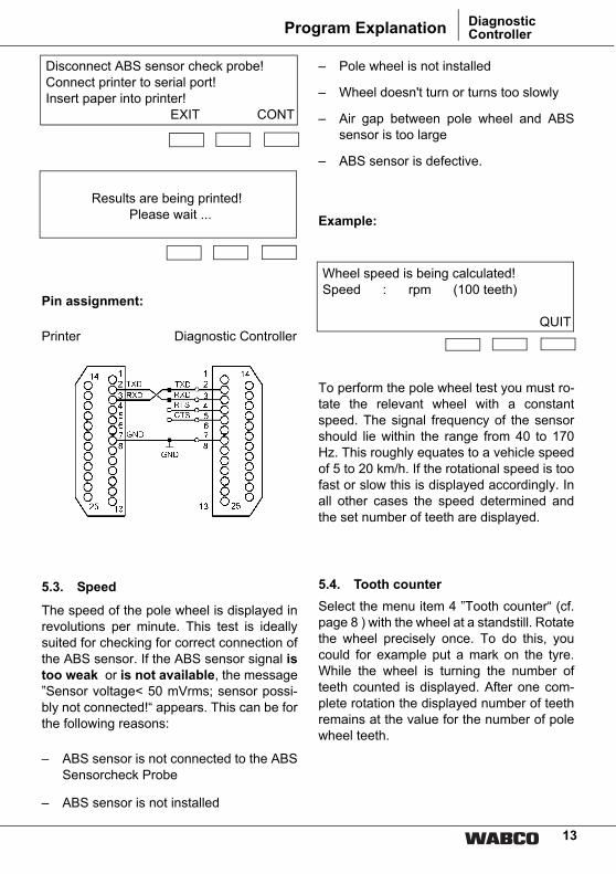
Disconnect ABS sensor check probe!Connect printer to serial port!Insert paper into printer!
EXIT CONT
Results are being printed! Please wait ...
Pin assignment:
Printer Diagnostic Controller
5.3. Speed
The speed of the pole wheel is displayed inrevolutions per minute. This test is ideallysuited for checking for correct connection ofthe ABS sensor. If the ABS sensor signal istoo weak or is not available, the message”Sensor voltage< 50 mVrms; sensor possi-bly not connected!“ appears. This can be forthe following reasons:
– ABS sensor is not connected to the ABSSensorcheck Probe
– ABS sensor is not installed
– Pole wheel is not installed
– Wheel doesn't turn or turns too slowly
– Air gap between pole wheel and ABSsensor is too large
– ABS sensor is defective.
Example:
Wheel speed is being calculated! Speed : rpm (100 teeth)
QUIT
To perform the pole wheel test you must ro-tate the relevant wheel with a constantspeed. The signal frequency of the sensorshould lie within the range from 40 to 170Hz. This roughly equates to a vehicle speedof 5 to 20 km/h. If the rotational speed is toofast or slow this is displayed accordingly. Inall other cases the speed determined andthe set number of teeth are displayed.
5.4. Tooth counterSelect the menu item 4 ”Tooth counter“ (cf.page 8 ) with the wheel at a standstill. Rotatethe wheel precisely once. To do this, youcould for example put a mark on the tyre.While the wheel is turning the number ofteeth counted is displayed. After one com-plete rotation the displayed number of teethremains at the value for the number of polewheel teeth.
Diagnostic ControllerProgram Explanation

14
Here are two examples:
Turn wheel exactly one revolution!Teeth: 104
QUIT
Result: The wheel was probably turned be-yond the marking. Rounding down to a”common“ number of teeth value (60, 80,100 or 120) gives: The pole wheel has 100teeth.
Turn wheel exactly one revolution!Teeth: 76
QUIT
Result: The pole wheel has 80 teeth. Thewheel was probably not turned right up to
the aforementioned tyre mark.
You can also rotate the wheel several timesand divide the value displayed by thenumber of revolutions. This increases theaccuracy when determining the number ofpole wheel teeth.
5.5 Multimeter
1 DC voltage 3 Resistance2 AC voltage
Select function! EXIT CONT
IMPORTANT:The measuring device is only designed formeasurements within the vehicle-relevantrange (low voltage). It may only be usedwithin the measuring ranges given below.
Range Display resolution Accuracy of the measuring range end value at 20°C
DC voltage2.0 V
20.0 V50.0 V
0.1 V 0.1 V 0.1 V
± 0,2 %± 0,2 %± 0,2 %
± 0.0 V± 0.1 V± 0.1 V
AC voltage2.0 V
35.0 V 0.01 V 0.1 V
± 0,6 %± 0,6 %
± 0.02 V± 0.4 V
Resistance20.0 Ω
200.0 Ω2.0 kΩ
20.0 kΩ95.0 kΩ
0.1 Ω 0.1 Ω 1.0 Ω
10.0 Ω 100.0 Ω
± 0,3 %± 0,2 %± 0,2 %± 0,1 %± 0,2 %
± 0.1 Ω± 0.1 Ω± 1.0 Ω
± 10.0 Ω± 100.0 Ω
DiagnosticController Program Explanation

15
5.7 Limit data for the test
System check mode (I), Service (S)
WABCO standard sensor:Permissible frequency range : 30 - 200 HzPermissible teeth : 40 - 120Permissible pole wheel diameter : 50 -280 mmUmin (I) : is calculated in Vrms (standard at 100 Hz)Umin (S) : 0.2 Vrms (standard at 100 Hz) Umax/Umin (I) : 2.0 -2.2 (depending on the level of the measured
sensor voltage)Umax/Umin (S) : 2.2 - 2,5 (depending on the level of the measured
sensor voltage)Amplitude error (I) : < 15% permissibleAmplitude error (S) : 1 15 - 30% error permissible*Half-cycle error (I) : < 10 % permissibleHalf-cycle error (S) : 1 10 -15 % error permissible*Total tooth pitch error (I) : < 1.5 degree
* (see following page)
Diagnostic ControllerProgram Explanation
The integrated multimeter function can beused to take electrical measurements on thevehicle. You only need to select the requiredmeasuring function
1 DC voltage2 AC voltage3 Resistance
The measuring range is automatically set bythe unit.
5.6 Options
1 ONLINE-Help2 Version
Select function! EXIT CONT
"Options" contains the following sub-items:
5.6.1 Online-help
This function enables the operator to receiveadditional explanations about operating thesystem. If this function is switched on, moredetailed explanations of the program appearat a suitable position between the programsteps.
5.6.2 Version
Hardware : V1 Multimeter: V1Operating system : V3.1 of 07.03.1991Program : V2.00 of 22.08.2002Checksum : BC 99 (hex) CONT
This function displays the delivered status ofthe controller and program card used:

16
WABCO mini sensor:Permissible frequency range : 30 - 200 HzPermissible teeth : 80 - 120Permissible pole wheel diameter : 100 -200 mmSensing ratio (l) : 0,45 - 0,65 Umax (I) : is calculated (standard at 100 Hz) Umin (I) : is calculated (standard at 100 Hz) Umin (S) : 0,11 Vrms (standard at 100 Hz) Umax/Umin (I) : 1.65 - 2.1Umax/Umin (S) : 1.75 - 2.2Amplitude error (I) : < 15 %Amplitude error (S) : 1 15 - 30% error*Half-cycle error (I) : < 10 %Half-cycle error (S) : 1 10 -15 % error*
* If an amplitude error of 15 - 30% and ahalf-cycle error of 10 - 15% occurs atthe same tooth during service, this isevaluated as 1 tooth profile deviation,i.e. pole wheel OK.If an amplitude error of 15 - 30% and ahalf-cycle error of 10 - 15% occurs atdifferent teeth during service, this isevaluated as 2 tooth profile deviations,i.e. pole wheel not ok.
6. TECHNICAL PARAMETERS
The ASP is supplied with an operating volt-age of 5 V (IB approx 60 mA) via the Diag-nostic Controller's power supply unit.
Storage temperature: - 40°C ... 70°C
Operating temperature: 0°C ... 70°C
Degree of protection to DIN 40050: IP20
The clock and data output and the internaloperating voltage of the ASP are to be elec-trically separated from the power supply andthe vehicle earth.
The ASP is installed in a plastic housing (BxHxD in mm 90x50x24).
DiagnosticController Program Explanation / Technical Parameters

17
Malfunctions and their causes:
No display
Black ”bar”
7. LOG PRINTOUT
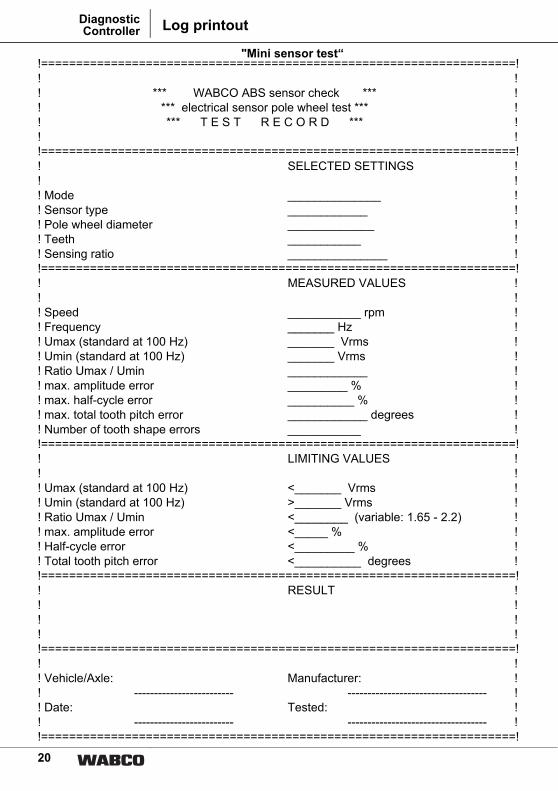
If it is not possible to printout the log with the Diagnostic Controller, the log on page 20 "Minisensor test“ or page 21 "Standard sensor test“ can be used and copies made on a photo-copier.
If necessary the form can be enlarged to A4 format before completing.
Examples of a mini sensor system check and a standard sensor service test record:
Cause Remedy
– No voltage
– Undervoltage (smaller than approx 7 V)
– If, after inserting the program card the display disappears, the program card is defective
– Check all plug-in connections
– Check power supply
– Replace program card
Cause Remedy
– Program card not inserted – Push in program card up to the limit stop (contacts facing upwards).
Diagnostic ControllerTechnical Parameters / Log printout

18
!====================================================================!! !! *** WABCO ABS sensor check *** !! *** electrical sensor pole wheel test *** !! *** T E S T R E C O R D *** !! !!====================================================================!! SELECTED SETTINGS !! !! Mode System check !! Sensor type Mini sensor !! Pole wheel diameter 140 mm !! Teeth 100 !! Sensing ratio 00.55 !!====================================================================!! MEASURED VALUES !! !! Speed 60.2 rpm !! Frequency 100.3 Hz !! Umax (standard at 100 Hz) 0.24 Vrms !! Umin (standard at 100 Hz) 0.23 Vrms !! Ratio Umax / Umin 1.04 !! max. amplitude error 2.4% !! max. half-cycle error 1.3% !! max. total tooth pitch error 0.3 degrees !! Number of tooth shape errors 0 !!====================================================================!! LIMITING VALUES ! !!! Umax (standard at 100 Hz) < 0.62 Vrms !! Umin (standard at 100 Hz) > 0.16 Vrms !! Ratio Umax / Umin < 1.81 (variable: 1.65 - 2.1) !! max. amplitude error < 15.0 % !! Half-cycle error < 10.0 % !! Total tooth pitch error < 1.5 degrees !!====================================================================!! RESULT !! !! Pole wheel and sensor voltage OK !! !!====================================================================!! !! Vehicle/Axle: Manufacturer: !! ------------------------- ----------------------------------- !! Date: Tested: !! ------------------------- ----------------------------------- !!====================================================================!
DiagnosticController Log printout

19
!====================================================================!! !! !! *** WABCO ABS sensor check *** !! *** electrical sensor pole wheel test *** !! *** T E S T R E C O R D *** !! !!====================================================================!! SELECTED SETTINGS !! !! Mode Service !! Sensor type Standard sensor !! Pole wheel diameter --- mm !! Teeth 120 !!====================================================================!! MEASURED VALUES !! !! Speed 50.1 rpm !! Frequency 100.3 Hz !! Umin (standard at 100 Hz) 0.48 Vrms !! Ratio Umax / Umin 1.02 !! max. amplitude error 2.0% !! max. half-cycle error 0.6 % !! Number of tooth shape errors 0 !!====================================================================!! LIMITING VALUES !! !! Umin (standard at 100 Hz) > 0.20 Vrms !! Ratio Umax / Umin < 2.38 (variable: 2.2 - 2.5) !! max. amplitude error < 30.0 % !! Half-cycle error < 15.0 % !!====================================================================!! RESULT !! !! Pole wheel and sensor voltage OK !! !!====================================================================!! !! Vehicle/Axle: Manufacturer: !! ------------------------- ----------------------------------- !! Date: Tested: !! ------------------------- ----------------------------------- !!====================================================================!
Diagnostic ControllerLog printout
20
!====================================================================!! !! *** WABCO ABS sensor check *** !! *** electrical sensor pole wheel test *** !! *** T E S T R E C O R D *** !! !!====================================================================!! SELECTED SETTINGS !! !! Mode ______________ !! Sensor type ____________ !! Pole wheel diameter _____________ !! Teeth ___________ !! Sensing ratio _______________ !!====================================================================!! MEASURED VALUES !! !! Speed ___________ rpm !! Frequency _______ Hz !! Umax (standard at 100 Hz) _______ Vrms !! Umin (standard at 100 Hz) _______ Vrms !! Ratio Umax / Umin ____________ !! max. amplitude error _________ % !! max. half-cycle error __________ % !! max. total tooth pitch error ____________ degrees !! Number of tooth shape errors ___________ !!====================================================================!! LIMITING VALUES !! !! Umax (standard at 100 Hz) <_______ Vrms !! Umin (standard at 100 Hz) >_______ Vrms !! Ratio Umax / Umin <________ (variable: 1.65 - 2.2) !! max. amplitude error <_____ % !! Half-cycle error <_________ % !! Total tooth pitch error <__________ degrees !!====================================================================!! RESULT !! !! !! !!====================================================================!! !! Vehicle/Axle: Manufacturer: !! ------------------------- ----------------------------------- !! Date: Tested: !! ------------------------- ----------------------------------- !!====================================================================!
"Mini sensor test“
DiagnosticController Log printout

21
!====================================================================!! !! *** WABCO ABS sensor check *** !! *** electrical sensor pole wheel test *** !! *** T E S T R E C O R D *** !! !!====================================================================!! SELECTED SETTINGS !! !! Mode ______________ !! Sensor type ____________ !! Pole wheel diameter _____________ !! Teeth ___________ !!====================================================================!! MEASURED VALUES !! !! Speed ___________ rpm !! Frequency _______ Hz !! Umin (standard at 100 Hz) _______ Vrms !! Ratio Umax / Umin ____________ !! max. amplitude error _________ % !! max. half-cycle error __________ % !! max. total tooth pitch error ____________ degrees !! Number of tooth shape errors ___________ !!====================================================================!! LIMITING VALUES !! !! Umin (standard at 100 Hz) >_______ Vrms !! Ratio Umax / Umin <________ (variable: 2.0 - 2.5) !! max. amplitude error <_____ % !! Half-cycle error <_________ % !! Total tooth pitch error <__________ degrees !!====================================================================!! RESULT !! !! !! !! !! !!====================================================================!! !! Vehicle/Axle: Manufacturer: !! ------------------------- ----------------------------------- !! Date: Tested: !! ------------------------- ----------------------------------- !!====================================================================
"Standard sensor test“
Diagnostic ControllerLog printout

22
DiagnosticController Circuit Diagram

23
Diagnostic ControllerCircuit Diagram

24
DiagnosticController Circuit Diagram

25
Diagnostic ControllerCircuit Diagram

26
DiagnosticController Circuit Diagram

27
Notes Diagnostic Controller

28
NotesDiagnosticController

© 2
005
Am
eric
an S
tand
ard
All
right
s re
serv
ed 8
15 0
10 0
86 3
/09.
2005
Vehicle Control SystemsAn American Standard Company
WABCO, the vehicle control sys-tems business of American Stand-ard Companies, is the world's leading producer of electronic braking, stability, suspension and transmission control systems for heavy duty commercial vehicles. WABCO products are also in-creasingly used in luxury cars and sport utility vehicles (SUVs). Cus-tomers include the world's leading commercial truck, trailer, bus and passenger car manufacturers.
Founded in the US 136 years ago as Westinghouse Air Brake Com-pany, WABCO was acquired by American Standard in 1968. Headquartered in Brussels, Bel-gium, the business today employs nearly 6700 people in 30 office and production facilities world-wide. In 2004, WABCO contribut-ed US$1.72 billion to American Standard's total sales of US$9.50 billion.Website: www.wabco-auto.com
WABCO WORLD-WIDE


