+ All Categories
Home > Documents > Differential Input and Output or Single Ended Input and ... · ©2010-2014 by Murata Electronics...

Differential Input and Output or Single Ended Input and ... · ©2010-2014 by Murata Electronics...

Date post: 12-Jun-2018
Category:
Upload: nguyenthien
View: 214 times
Download: 0 times
Share this document with a friend
12
©2010-2014 by Murata Electronics N.A., Inc. SF2094B (R) 4/7/14 Page 1 of 12 www.murata.com RFM products are now Murata products. 1. Unless noted otherwise, all specifications apply over the operating temperature range with filter soldered to the specified demonstration board with impedance matching to 50 Ω and measured with 50 Ω network analyzer. 2. Rejection is measured as attenuation below the minimum IL point in the passband. Rejection in final user application is dependent on PCB layout and external impedance matching design. See Application Note No. 42 for details. 3. The design, manufacturing process, and specifications of this filter are subject to change. 4. The turnover temperature, T O , is the temperature of maximum (or turnover) frequency, f o . The nominal frequency at any case temperature, T c , may be calculated from: f=f o [1-FTC(T o -T c ) 2 ]. 5. Tape and Reel Standard ANSI / EIA 481. 6. Either Port 1 or Port 2 may be used for either input or output in the design. However, impedances and impedance matching may vary between Port 1 and Port 2, so that the filter must always be installed in one direction per the circuit design. 7. US and international patents may apply. 8. Murata, stylized Murata logo, and Murata N.A., Inc. are registered trademarks of Murata Manufacturing Co., Ltd. Electrical Characteristics Characteristic Sym Notes Min Typ Max Units Nominal Center Frequency f C 1 379.9 380.00 380.1 MHz Insertion Loss 13.5 dB 3 dB Bandwidth BW 3 4.0 MHz Passband Variation CF ±1.7 MHz 0.5 1.5 dB CF ±1.85 MHz 2.3 3.5 dB Group Delay Variation CF ±1.7 MHz 250 nsec Reflected dB Return Loss 10 Triple Transit 35 After 1-2us 20 After 2-3us 35 After >3us 45 Ultimate Rejection DC to 180 MHz 30 dB 180 to 284 MHz 40 284 to 340 MHz 50 340 to 376.15 MHz 36 383.4 to 580 MHz 36 580 to 870 MHz 30 Maximum Peak RF Input Power 13 dBm Maximum RF Input Power Over Life 10 dBm Temperature Range Operating -15 85 °C Storage -40 85 Frequency Temperature Coefficient FTC 0.032 ppm/°C 2 Case Style SMP-03 7 x 5 mm Nominal Footprint Lid Symbolization (YY=year, WW=week, S=shift) RFM SF2094B YYWWS SMP-03 Low Insertion Loss 5.0 X 7.0 mm Surface-Mount Case Differential Input and Output or Single Ended Input and Output Complies with Directive 2002/95/EC (RoHS) Absolute Maximum Ratings Rating Value Units Maximum Incident Power in Passband +13 dBm Max. DC voltage between any 2 terminals 30 VDC Storage Temperature Range -40 to +85 °C Suitable for lead-free soldering - Max Soldering Temperature 260°C for 30 s 380.00 MHz SAW Filter SF2094B Pb CAUTION: Electrostatic Sensitive Device. Observe precautions for handling. NOTES:
Transcript

©2010-2014 by Murata Electronics N.A., Inc.SF2094B (R) 4/7/14 Page 1 of 12 www.murata.com

RFM products are nowMurata products.

1. Unless noted otherwise, all specifications apply over the operating temperature range with filter soldered to the specified demonstration board with impedance matching to 50 Ω and measured with 50 Ω network analyzer.

2. Rejection is measured as attenuation below the minimum IL point in the passband. Rejection in final user application is dependent on PCB layout and external impedance matching design. See Application Note No. 42 for details.

3. The design, manufacturing process, and specifications of this filter are subject to change.4. The turnover temperature, TO, is the temperature of maximum (or turnover) frequency, fo. The nominal frequency at any case temperature, Tc, may be

calculated from: f=fo[1-FTC(To-Tc)2].

5. Tape and Reel Standard ANSI / EIA 481.6. Either Port 1 or Port 2 may be used for either input or output in the design. However, impedances and impedance matching may vary between Port 1 and Port

2, so that the filter must always be installed in one direction per the circuit design.7. US and international patents may apply.8. Murata, stylized Murata logo, and Murata N.A., Inc. are registered trademarks of Murata Manufacturing Co., Ltd.

Electrical Characteristics

Characteristic Sym Notes Min Typ Max UnitsNominal Center Frequency fC 1 379.9 380.00 380.1 MHz

Insertion Loss 13.5 dB

3 dB Bandwidth BW3 4.0 MHz

Passband Variation CF ±1.7 MHz 0.5 1.5 dB

CF ±1.85 MHz 2.3 3.5 dB

Group Delay Variation CF ±1.7 MHz 250 nsec

Reflected

dB

Return Loss 10

Triple Transit 35

After 1-2us 20

After 2-3us 35

After >3us 45

Ultimate Rejection DC to 180 MHz 30

dB

180 to 284 MHz 40

284 to 340 MHz 50

340 to 376.15 MHz 36

383.4 to 580 MHz 36

580 to 870 MHz 30

Maximum Peak RF Input Power 13 dBm

Maximum RF Input Power Over Life 10 dBm

Temperature Range Operating -15 85°C

Storage -40 85

Frequency Temperature Coefficient FTC 0.032 ppm/°C2

Case Style SMP-03 7 x 5 mm Nominal Footprint

Lid Symbolization (YY=year, WW=week, S=shift) RFM SF2094B YYWWS

SMP-03

• Low Insertion Loss• 5.0 X 7.0 mm Surface-Mount Case• Differential Input and Output or Single Ended Input and Output• Complies with Directive 2002/95/EC (RoHS)

Absolute Maximum RatingsRating Value Units

Maximum Incident Power in Passband +13 dBm

Max. DC voltage between any 2 terminals 30 VDC

Storage Temperature Range -40 to +85 °C

Suitable for lead-free soldering - Max Soldering Temperature 260°C for 30 s

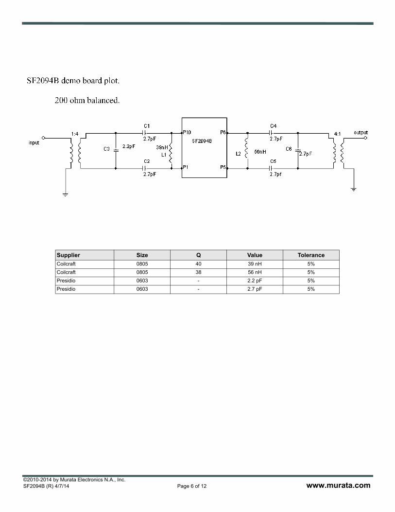
380.00 MHzSAW Filter

SF2094B

Pb

CAUTION: Electrostatic Sensitive Device. Observe precautions for handling.

NOTES:

©2010-2014 by Murata Electronics N.A., Inc.SF2094B (R) 4/7/14 Page 2 of 12 www.murata.com

SMP-03 Case

Recommended PCB Footprint

Case Dimensions

Dimension mm Inches

Min Nom Max Min Nom Max

A 6.80 7.00 7.20 0.268 0.276 0.283

B 4.80 5.00 5.20 0.189 0.197 0.205

C 1.50 1.65 2.00 0.059 0.065 0.079

D .47 0.60 .73 0.019 0.024 0.029

E 2.41 2.54 2.67 0.095 0.100 0.105

H 0.87 1.0 1.13 0.034 0.039 0.044

J 4.87 5.00 5.13 0.192 0.197 0.202

K 2.87 3.00 3.13 0.113 0.118 0.123

P 1.14 1.27 1.40 0.045 0.050 0.055

Materials

Solder Pad Termination

Au plating 30 - 60 µinches (76.2-152 µm) over 80-200 µinches (203-508 µm) Ni.

Lid Fe-Ni-Co Alloy Electroless Nickel Plate (8-11% Phos-phorus) 100-200 µinches Thick

Body Al2O3 Ceramic

Pb Free

Electrical Connections

Connection Terminals

Single Ended Operation Input 10

Output 5

Differential Operation Input 1, 10

Output 5, 6

Ground All others

RFM Matching Circuit Illustrated Seperately

A

B

C

H E

PD

H

J

K

10-Terminal Ceramic Surface-Mount Case

7 x 5 mm Nominal Footprint

©2010-2014 by Murata Electronics N.A., Inc.SF2094B (R) 4/7/14 Page 3 of 12 www.murata.com

©2010-2014 by Murata Electronics N.A., Inc.SF2094B (R) 4/7/14 Page 4 of 12 www.murata.com

Supplier Size Q Value Tolerance

Coilcraft 0805 60 47 nH 5%

Coilcraft 0805 60 39 nH 5%

Coilcraft 0805 60 6 nH 5%

Presidio 0603 - 18 pF 5%

Presidio 0603 - 8.2 pF 5%

©2010-2014 by Murata Electronics N.A., Inc.SF2094B (R) 4/7/14 Page 5 of 12 www.murata.com

©2010-2014 by Murata Electronics N.A., Inc.SF2094B (R) 4/7/14 Page 6 of 12 www.murata.com

Supplier Size Q Value Tolerance

Coilcraft 0805 40 39 nH 5%

Coilcraft 0805 38 56 nH 5%

Presidio 0603 - 2.2 pF 5%

Presidio 0603 - 2.7 pF 5%

©2010-2014 by Murata Electronics N.A., Inc.SF2094B (R) 4/7/14 Page 7 of 12 www.murata.com

COVER TAPE SIZE

KO

COVER TAPE0.32 mm ±0.3

2.15 mm ±0.2

W(CARRIER TAPE SIZE)

AO

BOP

(PITCH)

1.5 mm +0.1-0.0

4.0 mm ±0.1

2.0 mm ±0.1

1.75 mm ±0.1

7.5 mm ±0.1

1.5 mm +0.3-0.0

PIN #1

USER DIRECTION OF FEED

COMPONENT ORIENTATION and DIMENSIONS

Carrier Tape Dimensions

Ao 5.5 mm ±0.1

Bo 7.5 mm ±0.1

Ko 2.0 mm ±0.1

Pitch 8.0 mm ±0.1

W 16.0 mm ±0.3

©2010-2014 by Murata Electronics N.A., Inc.SF2094B (R) 4/7/14 Page 8 of 12 www.murata.com

Leader and Trailer specifications (Based upon EIA-481)

7 Inch Reel Quantity 500

Symbol A N C D B W1 W2

Dimension 178 +0-4

60 ±1 13 +0.5-0.2

20.2 +1.5-0

2 ±0.5 16.4 +2-0

22.4 MAX

13 Inch Reel Quantity 2000

Symbol A N C D B W1 W2

Dimension 330 +0-4

100 ±2 13 +0.5-0.2

20.2 +1.5-0

2 ±0.5 16.4 +2-0

22.4 MAX

Dimensions of the leader and trailer

Dimensional drawing of the reel

©2010-2014 by Murata Electronics N.A., Inc.SF2094B (R) 4/7/14 Page 9 of 12 www.murata.com

Additional items(1) Cover tape peeling strength The cover tape shall be adhered evenly to the carrier tape along both sides in the pulling direction.

The cover tape peeling strength shall be as follows for an angle between the cover tape and the pulling

direction of 165° to 180° (see the figure) and a peeling speed of 300mm/min. ±10mm/min.

[EIA-481] 0.1N to 1.3N for a tape width of 12 to 56mm

Tape material(1) Carrier tape [anti-charging treatment: carbon used] Surface resistivity: 1 x 10⁸ or less

Material: Polystyrene or Polycarbonate

(2) Cover tape material: Polyester (anti-charging treated) Surface resistivity: 1 x 10¹² or less

t = 50 to 100µm width = 13.3mm

Warranty periodsCover tape peeling strength and mounting performance of stored components.

2-1. Cover tape peeling strength: One year after delivery (Peeling strength: 0.1N to 1.3N)

Number of missing componentsThere shall not be two or more consecutive missing components. Also, the maximum number of missing

components shall be the larger of one piece or 0.1%.

Storage environmentKeep the product on which taping has been performed to a temperature below 40°C and a humidity within

80% RH. Do not subject in the direct sun.

Fixing method1. Insert the tip of the carrier tape into the groove.

2. Fix the tip of the cover tape with adhesive tape.

©2010-2014 by Murata Electronics N.A., Inc.SF2094B (R) 4/7/14 Page 10 of 12 www.murata.com

LabelingThe following items are labeled on the surface of a reel.

Product Part Number, Date Code, Quantity

©2010-2014 by Murata Electronics N.A., Inc.SF2094B (R) 4/7/14 Page 11 of 12 www.murata.com

7 InchReel

QuanityPer Reel

Number ReelsPer Carton

External CatonDimensions

ReelWeight

Shipping CartonWeight

TotalWeight

500 4 254 x 254 x 127 mm10 x 10 x 5 inches

896 g 448 g 1344 g

500 10 254 x 254 x 203 mm10 x 10 x 8 inches

2240 g 448 g 2688 g

13 InchReel

QuanityPer Reel

Number ReelsPer Carton

External CatonDimensions

ReelWeight

Shipping CartonWeight

TotalWeight

2000 2 356 x 356 x 102 mm14 x 14 x 4 inches

1288 g 448 g 1736 g

2000 4 356 x 356 x 178 mm14 x 14 x 7 inches

2576 g 448 g 3024 g

2000 8 356 x 356 x 356 mm14 x 14 x 14 inches

5152 g 448 g 5600 g

Package for Shipment

©2010-2014 by Murata Electronics N.A., Inc.SF2094B (R) 4/7/14 Page 12 of 12 www.murata.com

RFM Qualification and Reliability Test

Test Standard Test Parameters Measurement Criteria Results

1 Life atElevatedTemperature

MIL-STD-202Method 108Condition C

1,000 Hours125°C

Unbiased

Within Electrical & Hermetic Spec.(Note 1)

Pass

2 TemperatureCycling

JESD22Method JA-104

Air-to-Air

-55 ×Cto +125 ×C20 min. Dwell1,000 cycles

Pass

3 Vibration,VariableFrequency

MIL-STD-883Method 2007Condition B

50g Max.4 Cycles, 3 Axis20 Hz to 2 kHz to

20 Hz

Pass

4 MechanicalShock

MIL-STD-883Method 2002Condition B

1,500g Max.5 Shocks±3 Axis

Pass

5 DestructiveBondStrength

MIL-STD-883Method 2011Condition C

Wire Bond PullStrength

2.0 grams (After Seal) Pass

6 Die ShearStrength

MIL-STD-883Method 2019

Shear Strength 0.6 kg(Strength/area limit in

development)

Pass

7 Solderability(Note 2)

J-STD-002Method B

8 hr. steam age245 × C solder

temperature5 second dwell

>95% wetted surface Pass

8 PhysicalDimensions

JESD22Method JB-100

CriticalDimensions

Within specifications Pass

9 TemperatureCharacteristics

RFM Procedure Frequency overTemperature

Within specifications Pass

10 TerminalStrength(Note 2)

MIL-STD-833Method 2004

Condition A & D

Cond. A-LeadTension

Cond. B -PadAdhesionr 24

8 oz. - 30 sec.Visual Requirements & meets

Hermetic Spec.

Pass

11 Resistance toSolvents

MIL-STD-883Method 2015

Solvents a, b, d Visual Requirements Pass

12 Steady StateLife

MIL-STD-883Method 1005

1,000 HoursMax. Operating

TemperatureRated Voltage

Within Electrical & Hermetic Spec.(Note 1)

Pass

13 Internal Water-Vapor Content

MIL-STD-883Method 1018

< 5,001 PPM Pass

14 ConstantAcceleration

MIL-STD-883Method 2001Y1 Direction

30,000g Within Electrical & Hermetic Spec.(Note 1)

Pass

15 SubstrateAttach Strength

MIL-STD-883Method 2027

Tensile Strength ofDie Attachment

Custom per Device Pass


Recommended