H. OSTERBERG AND L. W. SMITH side of the plane. The magnification of the images in- creases as one looks at higher and higher orders. Con- sidering DiD 2 to be a horizontal plane, the images formed by light diffracted into the orders above the plane will be erect while those formed by light diffracted into orders below the plane will be upside down. A prism alone will form a single erect image if placed in the endfired beam with nearly the same orientation as that of prism R in Fig. 6. The receiving surface must be inclined slightly to the plane of the endfired beam when the inhomogeneous glass plate is absent. ACKNOWLEDGMENT The authors appreciate helpful discussions with Dr. Julius Kane of the University of Rhode Island on the nature and properties of surface waves. JOURNAL OF THE OPTICAL SOCIETY OF AMERICA VOLUME 54, NUMBER 9 SEPTEMBER 1964 Diffraction Effects of Coma RICHARD BARAKAT AND AGNES HOUSTON Optics Departmnent,Itek Corporation, Lexington, Massachusetts 02173 (Received 2 November 1963) The diffraction patterns of square and circular apertures having third-order coma are calculated by numerical techniques in the paraxial receiving plane. 1. INTRODUCTION A LTHOUGH coma is the most important off-axis aberration, very few studies have been made of its influence on the diffraction image owing to the com- plexity of the resultant diffraction integrals. Some previous calculations for the circular aperture were performed by Martin,' Kingslake, 2 Nienhuis, 2 Nijboer, 4 and Steward. 5 ' 6 A qualitative discussion of the main features of the comatic image for large values of coma was presented by van Kampen. 7 ' 8 A first step towards using machines is due to Marechall who developed an ingenious mechanical integrator and obtained a number of diffraction patterns of the Seidel aberrations. Both Kingslake and Nienhuis show valuable photographs of the comatic image. These pictures are also reproduced in Linfoot.' 0 We have adopted the principle that the main interest in such a study as we have undertaken are the final results and not the mathematical development of the integrals in question. Here the high-speed computer comes into its own in conjunction with the sophisticated 1 L. C. Martin, Monthly Notice Roy. Astron. Soc. 82,310 (1922). 2 R. Kingslake, Proc. Phys. Soc. (London) 61, 147 (1948). K. Nienhuis, "Image Formation in the Presence of Aberra- tions," thesis, Groningen (1948). 4 B. R. A. Nijboer, "The Diffraction Theory of Aberrations," thesis, Groningen (1942). s G. C. Steward, The Symmnietrical Optical Systew (Cambridge University Press, Cambridge, 1928), Chapt. 6. The reader is warned that the section on coma in this chapter contains a very large number of misprints. 'G. C. Steward, Phil. Trans. Roy. Soc. (London) A225, 131 (t925). 7 N. G. van Kampen, Physica 14, 575 (1949). 8 N. G. van Kampen, Physica 16, 817 (1950). 9A. Marechal, Rev. Opt. 27, 73 (1948). 10 E. H. Linfoot, Recent Advances in Optics (Oxford University Press, London, 1955). and efficient Gauss quadrature method of evaluating integrals. Steward 5 has proven that coma, unlike spherical aberration, does not benefit from a change of focus out of the paraxial receiving plane. Consequently, we have restricted ourselves to calculations in the paraxial re- ceiving plane only, as have all previous investigators. It would be interesting to perform calculations in other planes. We have chosen to make our computations for a closely spaced amount of coma in order to see how the diffraction pattern evolves as the coma is increased. In addition to studying the usual circular aperture, we have also considered the patterns associated with the square aperture. Lack of space forbids showing all the results. The complete set of graphs is available upon request. 2. SQUARE APERTURE We begin with the study of the square aperture. The point spread function (relative distribution of illumi- nance) of a square aperture with coma in the paraxial receiving plane is: 1 1 ,1 (2 t(Zl,Z2) =- efj li e2i V3x (zZ+y 2 )C i(z X+z2!)dxdy, (2.1) where zi, Z 2 are the dimensionless variables in the receiving plane," and x, y are the dimensionless vari- ables in the aperture. For convenience we will take = 27rW 3 as our measure of coma, where W 3 is the third- '1 For the convenience of those who wish to employ dimensional coordinates VI, V2 we have z, = (27ra/XJ)vs, Z 2 = (2xra/Xf)v2, where 2a is the length of the square aperture, f is the focal length of the objective, Xis the wavelength of light measured in the same units that VI, v2 employ (usually microns). Vol. 54 1084
Transcript
H. OSTERBERG AND L. W. SMITH
side of the plane. The magnification of the images in-creases as one looks at higher and higher orders. Con-sidering DiD 2 to be a horizontal plane, the imagesformed by light diffracted into the orders above theplane will be erect while those formed by light diffractedinto orders below the plane will be upside down.
A prism alone will form a single erect image ifplaced in the endfired beam with nearly the sameorientation as that of prism R in Fig. 6. The receiving
surface must be inclined slightly to the plane of theendfired beam when the inhomogeneous glass plateis absent.
ACKNOWLEDGMENT
The authors appreciate helpful discussions withDr. Julius Kane of the University of Rhode Island onthe nature and properties of surface waves.
JOURNAL OF THE OPTICAL SOCIETY OF AMERICA VOLUME 54, NUMBER 9 SEPTEMBER 1964
Diffraction Effects of Coma
RICHARD BARAKAT AND AGNES HOUSTON
Optics Departmnent, Itek Corporation, Lexington, Massachusetts 02173
(Received 2 November 1963)
The diffraction patterns of square and circular apertures having third-order coma are calculated bynumerical techniques in the paraxial receiving plane.
1. INTRODUCTION
A LTHOUGH coma is the most important off-axisaberration, very few studies have been made of
its influence on the diffraction image owing to the com-plexity of the resultant diffraction integrals. Someprevious calculations for the circular aperture wereperformed by Martin,' Kingslake, 2 Nienhuis, 2 Nijboer, 4
and Steward.5' 6 A qualitative discussion of the mainfeatures of the comatic image for large values of comawas presented by van Kampen.7' 8 A first step towardsusing machines is due to Marechall who developed aningenious mechanical integrator and obtained a numberof diffraction patterns of the Seidel aberrations. BothKingslake and Nienhuis show valuable photographs ofthe comatic image. These pictures are also reproducedin Linfoot.' 0
We have adopted the principle that the main interestin such a study as we have undertaken are the finalresults and not the mathematical development of theintegrals in question. Here the high-speed computercomes into its own in conjunction with the sophisticated
1 L. C. Martin, Monthly Notice Roy. Astron. Soc. 82,310 (1922).2 R. Kingslake, Proc. Phys. Soc. (London) 61, 147 (1948).K. Nienhuis, "Image Formation in the Presence of Aberra-
tions," thesis, Groningen (1948).4 B. R. A. Nijboer, "The Diffraction Theory of Aberrations,"
thesis, Groningen (1942).s G. C. Steward, The Symmnietrical Optical Systew (Cambridge
University Press, Cambridge, 1928), Chapt. 6. The reader iswarned that the section on coma in this chapter contains a verylarge number of misprints.
'G. C. Steward, Phil. Trans. Roy. Soc. (London) A225, 131(t925).
7 N. G. van Kampen, Physica 14, 575 (1949).8 N. G. van Kampen, Physica 16, 817 (1950).9 A. Marechal, Rev. Opt. 27, 73 (1948).10 E. H. Linfoot, Recent Advances in Optics (Oxford University
Press, London, 1955).
and efficient Gauss quadrature method of evaluatingintegrals.
Steward5 has proven that coma, unlike sphericalaberration, does not benefit from a change of focus outof the paraxial receiving plane. Consequently, we haverestricted ourselves to calculations in the paraxial re-ceiving plane only, as have all previous investigators.It would be interesting to perform calculations in otherplanes. We have chosen to make our computations fora closely spaced amount of coma in order to see how thediffraction pattern evolves as the coma is increased. Inaddition to studying the usual circular aperture, we havealso considered the patterns associated with the squareaperture.
Lack of space forbids showing all the results. Thecomplete set of graphs is available upon request.
2. SQUARE APERTURE
We begin with the study of the square aperture. Thepoint spread function (relative distribution of illumi-nance) of a square aperture with coma in the paraxialreceiving plane is:
where zi, Z2 are the dimensionless variables in thereceiving plane," and x, y are the dimensionless vari-ables in the aperture. For convenience we will take
= 27rW3 as our measure of coma, where W 3 is the third-
'1 For the convenience of those who wish to employ dimensionalcoordinates VI, V2 we have z, = (27ra/XJ)vs, Z2 = (2xra/Xf)v2, where2a is the length of the square aperture, f is the focal length of theobjective, X is the wavelength of light measured in the same unitsthat VI, v2 employ (usually microns).
Vol. 541084
DIFFRACTION EFFECTS OF COMA------ ---- --- --- --
F ~ ~ ~C 4- - -L-- -- 1 -1--J------
I I - L o, j 1
------- ---------- |-I I I 2
t (Z~1, Z2) COZ~d e~ [#~x+')jXd . (2 L.2 )---|-t
& I----1---e L|L.L L I
4--------- 4 - ------ L----.
NoTheis ne integral is an odd function of x, soence
only the cosine term need be considered; finally,
t (zI,z2) =J COSZ2Y COS[OX3+ (:X2- zl)xgdxdy . (2 .3)
In the absence of aberration (A = 0), this degenerates to
I I
I I
I-
I,
/ /
/ /4 4 /I / /
I I I
/ / CII �/ ,/
I icC
I-,I I /
I /cC
/ I' /
- -/ / /
4 4
'-N'
\ /4 /4
FIG. 2. Curves of constant illuminance for square aperture inparaxial receiving plane for system with (3=2(W 3 ==0.318X).
the usual expression
t (zl,z2) = [(sinzl/zi) (sinZ 2/Z 2 ) ]2,
1085
(2.4)
with the zeros of the pattern given by zi = n7r, z2 =n7r
(n= 1, 2, *--). The lines of constant illuminance areshown in Fig. 1. The dotted lines are the loci of zeroilluminance. The normalization on the graph is suchthat t(0,0) =1000, thus a line of constant illuminanceof 5 reads l=o0.005.
The actual calculations were performed by directapplication of Gauss quadrature.12 The double integralwas evaluated by employing a two-dimensional versionof 24-point Gauss quadrature and was programmed onthe PDP-1 computer. Both the integral and its squarewere calculated. For a fixed amount of coma we allowedz1 and Z2 to range over the values: z= -20(0.25)30,z2=0(0.25)20.
The results are shown in Figs. 2-5. The circle with
FIG. 3. Curves of constant illuminance for square aperture inparaxial receiving plane for system with 11= 3(W3 = 0.477X).
the small cross through it is the location of the point ofmaximum illuminance (Strehl criterion). The amountof change of aberration was chosen small enough toshow the rapid deterioration of the image. As small avalue as 13= 2 (W 3 = 0.318X) causes a discernable changein the image. The maximum of the pattern moves upalong the z1 axis and the whole pattern has started toshift into the upper half-plane with an accompanyingdistortion. The lines of zero illuminance are no longersquares. As ,B is successively increased, the image beginsto take on the coma pattern characteristic of geometricaloptics. The shapes of the patterns for 1> 12 canbe obtained from an application of stationary phasetechniques.
The maximum value of I (zl,z2) always occurs along
12 Z. Kopal, Nunmerical Analysis (John Wiley & Sons, Inc.,New York, 1955) Chap. 7.
September 1964
I
II II II II I
I
8{. B.ARAKATr AN)D A. HOUS VOVN
FIG. 4. Curves of constant illuminance for square aperture inparaxial receiving plane for system with (3= 6(W3 =0.955X).
the axis of the pattern Z2 = 0. This is determined by:
Oa(zs,o) Ir101 x sinD[x3+ (/y
2 -zl)x]dxdy= 0, (2.5)
where I= a I2. For small values of , we can solve thisintegral equation analytically. Replace the sine termby its argument and integrate
14 z 1(/X1+/y 2 x2 -_zix2 )d.xdy= -/--= 0, (2.6)
45 3
orZl,''= (14/15)/3= (28ir/15)W 3 . (2.7)
the coma coefficient W3. To test the range of validityof this linear proportionality we have evaluated theintegral Eq. (2.5) directly. The double integral wasprogrammed via double Gauss quadrature and uponinsertion of a given value of / a sequence of z. wascomputed until the integral changed sign. The valueswere then iterated in this vicinity. Calculations wereperformed at /=0(0.50)30. The calculations are sum-marized in Fig. 6 where it can be seen that the linearproportionality holds for d up to 2.0. Although the maxi-mum illuminance tends away from the geometric centerwith increasing /, it actually reverses itself in a seriesof slowly undulating waves. This behavior was notexpected but also occurred for the slit and circularapertures as we soon see. The value that the maxi-mum illuminance (Strehl criterion) takes is obtainablefrom (2.3) by inserting the appropriate value of A andits corresponding zip. The curves are shown in Fig. 7.
SQUARE APERTURE
; 18
THIRD ORDER COMA COEFFICIENT P
The distance zits that the maximum of the patterndeparts from the geometric center13 is proportional to
1I1G. 5. Curves of constant illuminance for square aperture inparaxial receiving plane for system with = 12(W 3 = 1.910X).
13 The geometric center of the diffraction pattern is defined asthe intersection of the principal ray with the receiving plane; inour case it is the paraxial receiving plane.
FIG. 6. Distance from the geometric center to the point of maxi-mum illuminance as a function of d for square aperture.
The Strehl criterion is very sensitive to coma and ac-cepting the usual tolerance of Strehl criterion of 0.8 orgreater as a well-corrected system, we see that this limitis reached at 0-2(W,-0.32X). Note the correspondingcurve for the circular aperture (Sec. 3).
3. CIRCULAR APERTURE
The point spread function of a circular aperture withcoma in the paraxial receiving plane is
Cr 21= J Je22 iV3(X2+y2)Xe-i(z'Z+-2Y)dxdYI (3.1)
where the integration is over the area of the circularaperture. We must convert to polar coordinates in bothimage and exit planes. Let
X=p1 cosos Z ZOSQ (3.2)
y=pI sin, Z2 = Z sink,
then it is simple to show that/3x(x2 +y2 )- (ZIX+z2Y)=/p 1
3 cosO-p1 Z cos(0- 0), (3.3)
so that the point spread function reads
t(z 0)= / eip' 3 COR¢plZ eoR(e)pidpido. (3.4)
0
1()86 Vtol. 54
z4 30
------ 11 1, 1,I 'I,
I
I:E7I'j9I2ISI-1. 3Ily
Zr;i
0
S 1 DIFFRACTION EFFECTS OF COMA 1
Setting pi2=p and performing the integration over 4)
where z, 0 are the dimensionless polar coordinates in theimage plane.14 When / vanishes, this reduces to theusual expression for the Airy disc
1(z) = [2J 1 (z)/z]2. (3.6)
The integral (and its'square) were evaluated by 32-pointGauss quadrature and the following scheme wasadopted. Computations were performed at fixed 0 andz ran from zero out to the desired value. For a fixedamount of coma, we allowed z and 0 to range over thevalues: z=0(0.25)30,0=00(50)1800, which is about 4500data points per set.jThe data were reduced by theprocedure described in Sec. 2 and the results exhibitedin Figs. 8-11. As /3 increases, the central region of the
,.0
.8
.6 A SQUARE APERTURE
B CIRCULAR APERTURE
4 B
0 6 12 18 24 30
THIRD ORDER COMA COEFFICIENT /3
FIG. 7. Maximum illuminance (Strehl criterion) as a function ofd for square and circular apertures.
image shifts into the upper half plane and the circlesbreak up into horseshoe-shaped forms of varying com-plexity. Note that the outer circles of zero illuminanceare only slightly distorted, in accordance with somegeneral considerations of Steward.1' 6 The reader shouldcompare these diagrams with the beautiful photographsobtained by Kingslake,2 which were reprinted byLinfoot.' 0
The maximum illuminance occurs on the (0= 00)axis of the figure. Now
a (z,O) = Jo[(z 2p-2Z/p
2 +- p 3) l zdp
I
J o[pi (z2- 2z/p±+/2 p2) ']dp
Jo[p(z-3p)]dp,
/
I .
I I
I I II I I
I II I II I& I d I
I I
I1 \\
, 29
II
18p
FIG. 8. Curves of constant illuminance for circular aperture inparaxial receiving plane for system with f = 2 (W3 = 0.318X).
and the maxima are determined by
aa(zO) Il'___= I pUJ[zp'-0p']dp= 0,
AZ Jo(3.8)
since Jot(x)= -J 1 (x). For small values of /3, z will alsobe small and we can replace fl by its argument andintegrate; consequently,
3e (on 0= 0°). (3.9)
As in the square aperture, we again have a linear
(3.7)
I 2ISH _2
I
14 To convert to the dimensional coordinate v, we employz= (27ra/Xf)v where a is the radius of the aperture, f is the focallength of the objective, X is the wavelength of light measured inthe same unit that v employs (usually microns).
1 80c
FIG. 9. Curves of constant illuminance for circular aperture inparaxial receiving plane for system with a = 3 (W3 = 0.477X).
September 1964 1087
eo
" �_ I
kI
II
III
-IF -I
II
II I
R. BARAKAT AND A. HOUSTON V .r
o. puted from (3.1) by substituting the appropriate valueof (3 and its corresponding zm. This curve is shown inFig. 7. The circular aperture is capable of tolerating a
,/ 10 \ much greater amount of coma than the square aperture.The Rayleigh limit of Strehl criterion equal to 0.8 isi5 3-\-4, which is twice that of a square aperture.
4. EPILOGUE
' a .\ vi! Although we have calculated the corresponding20 s/ / lquantities for the slit aperture, we have not included20 ' , A / 20 them in this paper. The distance from the geometric
center zn is given by\ \ -- ,
\ (<6) (4.1)
-- - --- - ' For values of 3>6, we encounter the undulatory be-T -- havior already noted in the square and circular aper-
tures. Note that the slope of Z versus ( is greatest forthe square aperture and least for the slit aperture,
180.0
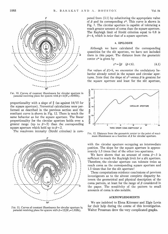
FIC. 10. Curves of constant illuminance for circular aperture in zparaxial receiving plane for system with f= 6(W3=0.955X). U
o 6.0
proportionality with a slope of 3 (as against 14/15 for E
the square aperture). Numerical calculations were per- 0 40 / CIRCULAR APERTURE
formed as described in the previous section and the E
resultant curve is shown in Fig. 12. There is much the /same behavior as for the square aperture. The linear /proportionality for the circular aperture holds over agreater range (up to (-5) than the corresponding 0o 6 '' 24 30
square aperture which held up to (-2. THIRD ORDER COMA COEFFICIENT /3
The maximluml intensity (Strehl criterion) is com-FIG. 12. Distance from the geometric center to the point of maxi-
mum illuminance as a function of d for circular aperture.
with the circular aperture occupying an intermediateposition. The slope for the square aperture is approx-imately 1.5 times that of the other two apertures.
10 , \ We have shown that an amount of coma (-3 is2 /~ N /sufficient to reach the Rayleigh limit for a slit aperture.
// \ Therefore, the circular aperture can tolerate twice asm|nuch coma as the corresponding square aperture and1.5 times that for the slit aperture!
k I These computations reinforce conclusions of previous/ investigators as to the alnost complete disparity be-
, , tween the geometrical and physical description of the-- > / ,' / coma pattern, at least for the range of ( considered in
\" / / 22 the paper. The sensitivity of the pattern to smalls a' Aamounts of coma is also notable.
ACKNOWLEDGMENTS
ii& We are indebted to Elena Kitrosser and Elgie Levin
FIG. 11. Curves of constant illuminance for circular aperture in for their help during the course of this investigation.paraxial receiving plane for system with i3= 12(W 3= 1.910X). Walter Prussman drew the very complicated graphs.