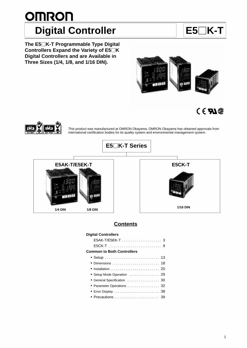
Digital Controller E5 K-TThe E5K-T Programmable Type DigitalControllers Expand the Variety of E5 KDigital Controllers and are Available inThree Sizes (1/4, 1/8, and 1/16 DIN).
RC
This product was manufactured at OMRON Okayama. OMRON Okayama has obtained approvals frominternational certification bodies for its quality system and environmental management system.
Compact and Easy-to-use Controllers Programming is as easy as following the steps below.
Program can be set in pattern 0 according to the following proce-dure.
Step 1 Step 2 Step 3100
50
SP
0.20 0.40 0.20
Time: hours and minutes
Step No. Target value Time(hours.minutes)
0 50 0.00
1 100 0.20
2 100 0.40
3 50 0.20
1. Press the Display Key to shift to the displayfor the number of steps.
5no
0 8
Parameter for the number ofsteps used
Number of steps (Default setting: 8)
Pattern No.
Display key
2. Press the Down Key and set the number ofsteps.
5no
0 4 Four steps in this case
Down key
3. Press the Display Key to shift to the displayfor the target value of step 0.
Step 0Parameter of the target value
Target value(Default setting: 0)
5p0
0 0
Display key
4. Set the target value to “50.”
5p0
0 50 Target value
Up key
5. Press the Display Key to shift to the displayfor the time of step 0.
ti0
0 000
Time parameter for step 0.
Step time(Default setting: 0.00)
Pattern No.
Display key
6. Press the Display Key again with the steptime set at 0 minutes, and the target valueparameter for step 1 will be displayed.
5p1
0 0
Display key
7. Press the Up Key to increment to “100.”
5p1
0 100
Up key
In the same manner, set the time for step 1, tar-get value for step 2, time for step 2, etc.When the target value and time settings arecomplete, press the Display Key.
3
Digital Controller E5AK-T/E5EK-T
Advanced Programmable DigitalControllers Ideal for Worldwide Use
Offers up to eight patterns of simple programmingcontrol (16 steps per pattern).
Modular structure, one-stock type
High-accuracy: 100-ms sampling (for analog input)
Conforms to international EMC and safetystandards.
IP66/NEMA4 (indoor use) front face
Serial communications (RS-232C, RS-422 andRS-485) and transfer output (4 to 20 mA)
Position-proportional control model
Heat/Cool control
24VAC/DC types are also available.
RC
Ordering InformationDescription Model Specification
Base Unit E5AK-TAA2 AC100-240 Standard modelase U
E5AK-TAA2-500 AC100-240 Standard model with terminal cover
E5AK-TAA2 AC/DC24 Standard model
E5AK-TAA2-500 AC/DC24 Standard model with terminal cover
E5AK-TPRR2 AC100-240 Position-proportional model
E5AK-TPRR2-500 AC100-240 Position-proportional model with terminal cover
E5AK-TPRR2 AC/DC24 Position-proportional model
E5AK-TPRR2-500 AC/DC24 Position-proportional model with terminal cover
E5EK-TAA2 AC100-240 Standard model
E5EK-TAA2-500 AC100-240 Standard model with terminal cover
E5EK-TAA2 AC/DC24 Standard model
E5EK-TAA2-500 AC/DC24 Standard model with terminal cover
E5EK-TPRR2 AC100-240 Position-proportional model
E5EK-TPRR2-500 AC100-240 Position-proportional model with terminal cover
E5EK-TPRR2 AC/DC24 Position-proportional model
E5EK-TPRR2-500 AC/DC24 Position-proportional model with terminal cover
Note: 1. When using the heater burnout alarm function with a standard model, the Linear Output Unit cannot be used for the control outputs(heat).
2. Be sure to specify the Current Transformer, Output Unit, and Option Unit when ordering.
E5AK-T/E5EK-T E5AK-T/E5EK-T
4
Description Model Specification
Output Unit E53-R Relay
E53-S SSR
E53-Q Pulse (NPN) 12 VDC at 40 mA max.
E53-Q3 Pulse (NPN) 24 VDC at 20 mA max.
E53-Q4 Pulse (PNP) 24 VDC at 20 mA max.
E53-C3 Linear (4 to 20 mA) under a load of 600 Ω max.
E53-C3D Linear (0 to 20 mA) under a load of 600 Ω max.
E53-V34 Linear (0 to 10 V) under a load of 1 kΩ min.
E53-V35 Linear (0 to 5 V) under a load of 1 kΩ min.
Note: The Digital Controller uses a dedicated, high-resolution Output Unit. The E53-C Current Output Unit for the E5X cannot be used withthe Digital Controller.
Description Model Specification
Option Unit E53-AKB Event input
E53-AK01 Communication (RS-232C)
E53-AK02 Communication (RS-422)
E53-AK03 Communication (RS-485)
E53-AKF Transfer output
Note: 1. The Option Unit can be used either by the E5AK or E5EK.
2. The E5AK allows a maximum of three Option Units to be mounted. Refer to page 13 for mounting combinations. The E5EK allows only one Option Unit to be mounted.
Inspection ReportThe Digital Controller can be provided together with an inspection report.
Refer to the following legend with the suffix “K” when ordering a model provided together with an inspection report.E5K-TAA2-K, E5K-TPRR2-K
Accessories (Order Separately)Name Model Hole diameter
Current Transformer E54-CT1 5.8 dia.
E54-CT3 12.0 dia.
Note: No CT is required unless the heater burnout alarm function is used.
Name Model Connectable models
Terminal Cover E53-COV0809 E5AK
E53-COV08 E5EK
Unit LabelModel Y92S-L1
RangesPlatinum Resistance Thermometer
Input (switch selectable) JPt100 Pt100
Range °C –199.9 to 650.0 –199.9 to 650.0
°F –199.9 to 999.9 –199.9 to 999.9
Setting 0 1
ThermocoupleInput (switchselectable)(see note)
K1 K2 J1 J2 T E L1 L2 U N R S B W PLII
Range °C –200to1,300
0.0 to500.0
–100to850
0.0 to400.0
–199.9to400.0
0 to600
–100to850
0.0 to400.0
–199.9to400.0
–200to1,300
0 to1,700
0 to1,700
100to1,800
0 to2,300
0 to1,300
°F –300to2,300
0.0 to900.0
–100to1,500
0.0 to750.0
–199.9to700.0
0 to1,100
–100to1,500
0.0 to750.0
–199.9to700.0
–300to2,300
0 to3,000
0 to3,000
300to3,200
0 to4,100
0 to2,300
Setting 2 3 4 5 6 7 8 9 10 11 12 13 14 15 16
Note: Setting number is factory-set to 2 (K1).
E5AK-T/E5EK-T E5AK-T/E5EK-T
5
Current/Voltage
Input (switch selectable) Current input Voltage input
4 to 20 mA 0 to 20 mA 1 to 5 V 0 to 5 V 0 to 10 V
Range One of following ranges depending on results of scaling–1999 to 9999–199.9 to 999.9–19.99 to 99.99–1.999 to 9.999
Setting 17 18 19 20 21
Specifications Ratings
Item 100- to 240-VAC type 24-VAC/VDC type
Supply voltage 100 to 240 VAC, 50/60 Hz 24 VAC/VDC, 50/60 Hz
Power consumption E5AK: 16 VAE5EK: 15 VA
12 VA, 8 W
Operating voltage range 85% to 110% of rated supply voltage
Sensor input Thermocouple: K, J, T, E, L, U, N, R, S, B, W, PLIIPlatinum resistance thermometer: JPt100, Pt100Current input: 4 to 20 mA, 0 to 20 mA (Input impedance: 150 Ω)Voltage input: 1 to 5 V, 0 to 5 V, 0 to 10 V (Input impedance: 1 MΩ)
Control output According to Output Unit (see Output Unit Ratings and Characteristics)
Auxiliary output SPST-NO, 3 A at 250 VAC (resistive load)
Control method ON/OFF or 2-PID control (with auto-tuning)
Setting method Digital setting using front panel keys
Indication method 7-segment digital display and LEDs
Event input Contact input: ON: 1 kΩ max., OFF: 100 kΩ min.No-contact input: ON: residual voltage: 1.5 V max., OFF: leakage current: 0.1 mA max.
Transfer output 4 to 20 mA, permissible load impedance: 600 Ω max., resolution: approx. 2,600
Current T ransformer input Connect an exclusive Current Transformer (E54-CT1 or E54-CT3)
Other functions StandardManual output, heating/cooling control, SP limiter, loop burnout alarm, MV limiter, MV changerate limiter, input digital filter, input shift, run/reset, protect functions, scaling function
E5AK-T/E5EK-T E5AK-T/E5EK-T
6
CharacteristicsIndication accuracy (see note) Thermocouple:
(±0.3% of indication value or ±1°C, whichever greater) ±1 digit max.
Platinum resistance thermometer:(±0.2% of indication value or ±0.8°C, whichever greater) ±1 digit max.
Analog input: ±0.2% FS ±1 digit max.
Hysteresis 0.01% to 99.99% FS (in units of 0.01% FS)
Proportional band (P) 0.1% to 999.9% FS (in units of 0.1% FS)
Integral (reset) time (I) 0 to 3,999 s (in units of 1 s)
Derivative (rate) time (D) 0 to 3,999 s (in units of 1 s)
Control period 1 to 99 s (in units of 1 s)
Manual reset value 0.0% to 100.0% (in units of 0.1%)
Alarm setting range –1,999 to 9,999 or –199.9 or 999.9 (decimal point position dependent on input type or result ofscaling)
Set time 0 to 99 hrs 59 min or 0 to 99 min 59 s
Program capacity 8 patterns (E5AK) or 4 patterns (E5EK), 16 steps
Programming method Time or ramp setting method
Time accuracy ±0.2% (±500 ms) of the set value
Sampling period Temperature input: 250 msAnalog input: 100 ms
Insulation resistance 20 MΩ min. (at 500 VDC)
Dielectric strength 2,000 VAC, 50/60 Hz for 1 min between terminals of different polarities
Vibration resistance Malfunction: 10 to 55 Hz, 10 m/s2 (approx. 1G) for 10 min each in X, Y, and Z directionsDestruction: 10 to 55 Hz, 20 m/s2 (approx. 2G) for 2 hrs each in X, Y, and Z directions
Shock resistance Malfunction: 200 m/s2 min. (approx. 20G), 3 times each in 6 directions(100 m/s2 (approx. 10G) applied to the relay)
Destruction: 300 m/s2 min. (approx. 30G), 3 times each in 6 directions
Ambient temperature Operating: –10°C to 55°C (with no icing)/3-year warranty period: –10°C to 50°CStorage: –25°C to 65°C (with no icing)
Ambient humidity Operating: 35% to 85%
Enclosure ratings Front panel: NEMA4 for indoor use (equivalent to IP66)Rear case: IEC standard IP20Terminals: IEC standard IP00
Memory protection Non-volatile memory (number of writings: 100,000 operations)
Approved standards UL1092, CSA22.2 No. 14, CSA C22.2 No. 142Conforms to EN50081-2, EN50082-2, EN61010-1 (IEC1010-1)Conforms to VDE0106/part 100 (Finger Protection), when the separately-ordered terminalcover is mounted.
Note: The indication accuracy of the K1, T, and N thermocouples at a temperature of -100°C max. The indication accuracy of the U, L1, andL2 thermocouples at any temperature is ±2°C ±1 digit maximum.The indication accuracy of the B thermocouple at a temperature of 400°C max. is unrestricted.The indication accuracy of the R and S thermocouples at a temperature of 200°C max. is ±3°C ±1 digit maximum.The indication accuracy of the W thermocouple at any temperature is (±0.3% of the indicated value or ±2°C, whichever is greater)±1 digit maximum.The indication accuracy of the PLII thermocouple at any temperature is (±0.3% of the indicated value or ±2°C, whichever is greater) ±1digit maximum.
E5AK-T/E5EK-T E5AK-T/E5EK-T
7
Output Unit Ratings and CharacteristicsModel Specifications
E53-R Relay output 5 A at 250 VAC (resistive load)
E53-S SSR output 1 A at 75 to 250 VAC (resistive load)
E53-Q Voltage output NPN: 40 mA at 12 VDC (with short-circuit protection)
E53-Q3 NPN: 20 mA at 24 VDC (with short-circuit protection)
E53-Q4 PNP: 20 mA at 24 VDC (with short-circuit protection)
E53-C3 Linear current output 4 to 20 mA, permissible load impedance: 600 Ω max., resolution: approx. 2,600
E53-AKF Transfer output 4 to 20 mA:Permissible load impedance: 600 Ω max.Resolution: approx. 2,600
Note: Event input is used for switching the target value, run or stop command, or automatic and manual mode with an external signal input.
Current Transformer RatingsDielectric strength 1,000 VAC (for 1 min)
Vibration resistance 50 Hz, 98 m/s2 (10G)
Weight E54-CT1: approx. 11.5 g; E54-CT3: approx. 50 g
Accessories (E54-CT3 only) Armature: 2; Plug: 2
Heater Burnout AlarmMax. heater current Single-phase 50 A VAC (see note 1)
Heater current value display accuracy ±5% FS±1 digit max.
Heater burnout alarm setting range 0.1 to 49.9 A (in units of 0.1 A) (see note 2)
Min. detection ON time 190 ms (see note 3)
Note: 1. Use the K2CU-FA-GS (with gate input terminals) for the detection of three-phase heater burnout.
2. The heater burnout alarm is always OFF if the alarm is set to 0.0 A and always ON if the alarm is set to 50.0 A.
3. No heater burnout detection or heater current value measurement is possible if the control output (heat) is ON for less than 190 ms.
E5AK-T/E5EK-T E5AK-T/E5EK-T
8
NomenclatureE5AK
E5EK
Operation Indicators
• OUT1Lit when the pulse output functionassigned to control output 1 turns ON.
• OUT2Lit when the pulse output functionassigned to control output 2 turns ON.
• SUB1Lit when the output function assignedto auxiliary output 1 turns ON.
• SUB2Lit when the output function assignedto auxiliary output 2 turns ON.
• MANULit when the manual operation mode.
• RSTLit when the operation is reset.
• RMTLit during remote operation.
• ATFlashes during auto-tuning.
• HOLDLit when the program is on hold.
• WAITLit when the program is waiting.
RUN/RST Key
Switches between RUN and RESET mode.
Display 1
Displays the process value orparameter code.
Display 2
Displays the present SP, manip-ulated variable, or parametersettings.
Up Key/Down Key
Press to increase or decreasethe value on the No.2 display.
RUN/RST Key
Display Key
Display 1
Display 2
Operation indicators
Up Key/Down Key
Pattern Number
Indicates the pattern number.
Display Key
Press to shift the display to thenext parameter.
Program Status Indicators
The top indicator indicates the risingstep, the middle indicator indicates theconstant step, and the bottom indicatorindicates the falling step.
Bar Graph
Indicates the rate of pattern elaps-ing time at the rate of 20% (5 lev-els) per one segment.
Pattern Number
9
Digital Controller E5CK-TAdvanced, Compact ProgrammableDigital Controllers Ideal for WorldwideUse
Offers up to four patterns of simple programmingcontrol (16 steps per pattern).
IP66/NEMA4 (indoor use) front face.
Modular structure, one-stock type.
Heat/Cool control.
Serial communications (RS-232C and RS-485).
Temperature and analog inputs.
High-accuracy: 100-ms sampling (for analoginput).
Conforms to international EMC and safetystandards.
24 VAC/DC types are also available.
Ordering InformationDescription Model Specification
Base Unit E5CK-TAA1 AC100-240 Standard model
E5CK-TAA1-500 AC100-240 Standard model with terminal cover
E5CK-TAA1 AC/DC24 Standard model
E5CK-TAA1-500 AC/DC24 Standard model with terminal cover
Note: A single Output Unit and Option Unit can be mounted to each Base Unit.
Description Model Specification
Output Unit E53-R4R4 Relay/Relay
E53-Q4R4 Pulse (NPN)/Relay
E53-Q4HR4 Pulse (PNP)/Relay
E53-C4R4 Linear (4 to 20 mA)/Relay
E53-C4DR4 Linear (0 to 20 mA)/Relay
E53-V44R4 Linear (0 to 10 V)/Relay
E53-Q4Q4 Pulse (NPN)/Pulse (NPN)
E53-Q4HQ4H Pulse (PNP)/Pulse (PNP)
Description Model Specification
Option Unit E53-CK01 RS-232C
E53-CK03 RS-485
E53-CKB Event input: 1 point
E53-CKF Transfer output (4 to 20 mA)
Inspection ReportThe Digital Controller can be provided together with an inspection report.
Refer to the following legend with the suffix “K” when ordering a model provided together with an inspection report.E5CK-TAA1-K
Accessories (Order Separately)Name Model
Terminal Cover E53-COV07
E5CK-T E5CK-T
10
Temperature RangesPlatinum Resistance Thermometer
Input (switch selectable) JPt100 Pt100
Range °C –199.9 to 650.0 –199.9 to 650.0
°F –199.9 to 999.9 –199.9 to 999.9
Resolution ( °C/°F)(main setting and alarm)
0 1
Thermocouple
Input (switchselectable)(see note)
K1 K2 J1 J2 T E L1 L2 U N R S B W PLII
Range °C –200to1,300
0.0 to500.0
–100to850
0.0 to400.0
–199.9to400.0
0 to600
–100to850
0.0 to400.0
–199.9to400.0
–200to1,300
0 to1,700
0 to1,700
100to1,800
0 to2,300
0 to1,300
°F –300to2,300
0.0 to900.0
–100to1,500
0.0 to750.0
–199.9to700.0
0 to1,100
–100to1,500
0.0 to750.0
–199.9to700.0
–300to2,300
0 to3,000
0 to3,000
300to3,200
0 to4,100
0 to2,300
Resolution(°C/°F)(main settingand alarm)
2 3 4 5 6 7 8 9 10 11 12 13 14 15 16
Note: Setting number is factory-set to 2 (K1).
Current/Voltage
Input (switch selectable) Current input Voltage input
4 to 20 mA 0 to 20 mA 1 to 5 V 0 to 5 V 0 to 10 V
Range One of following ranges depending on results of scaling–1999 to 9999–199.9 to 999.9–19.99 to 99.99–1.999 to 9.999
Resolution ( °C/°F)(main setting and alarm)
17 18 19 20 21
Specifications Ratings
Item 100- to 240-VAC type 24-VAC/VDC type
Supply voltage 100 to 240 VAC, 50/60 Hz 24 VAC/VDC, 50/60 Hz
Power consumption 15 VA 6 VA, 3.5 W
Operating voltage range 85% to 110% of rated supply voltage
Sensor input Thermocouple: K, J, T, E, L, U, N, R, S, B, W, PLIIPlatinum resistance thermometer: JPt100, Pt100Current input: 4 to 20 mA, 0 to 20 mAVoltage input: 1 to 5 V, 0 to 5 V, 1 to 10 V
Input impedance Current input: 150 ΩVoltage input: 1 MΩ min.
Control output According to Output Unit (see Output Unit Ratings and Characteristics)
Auxiliary output SPST-NO, 3 A at 250 VAC (resistive load)
Control method ON/OFF or 2-PID control
Setting method Digital setting using front panel keys
Indication method 7-segment digital display and LEDs
Other functions StandardManual output, heating/cooling control, SP limiter, loop burnout alarm, MV limiter, MV changerate limiter, input digital filter, input shift, run/reset, protect functions, scaling function
E5CK-T E5CK-T
11
CharacteristicsIndication accuracy (see note 1) Thermocouple:
(±0.3% of indication value or ±1°C, whichever greater) ±1 digit max.
Platinum resistance thermometer:(±0.2% of indication value or ±0.8°C, whichever greater) ±1 digit max.
Analog input: ±0.2% FS ±1 digit max.
Hysteresis 0.01% to 99.99% FS (in units of 0.01% FS)
Proportional band (P) 0.1% to 999.9% FS (in units of 0.1% FS)
Integral (reset) time (I) 0 to 3,999 s (in units of 1 s)
Derivative (rate) time (D) 0 to 3,999 s (in units of 1 s)
Control period 1 to 99 s (in units of 1 s)
Manual reset value 0.0% to 100.0% (in units of 0.1%)
Alarm setting range –1,999 to 9,999 or –199.9 or 999.9 (decimal point position dependent on input type)
Program capacity 4 patterns, 16 steps (possible to use up to 4 patterns with the communications function.)
Programming method Time or ramp setting method
Time accuracy ±0.2% (±500 ms) of the set value
Sampling period (see note 2) Temperature input: 250 msAnalog input: 100 ms
Insulation resistance 20 MΩ min. (at 500 VDC)
Dielectric strength 2,000 VAC, 50/60 Hz for 1 min between terminals of different polarities
Vibration resistance Malfunction: 10 to 55 Hz, 10 m/s2 (approx. 1G) for 10 min each in X, Y, and Z directionsDestruction: 10 to 55 Hz, 20 m/s2 (approx. 2G) for 2 hrs each in X, Y, and Z directions
Shock resistance Malfunction: 200 m/s2 min. (approx. 20G), 3 times each in 6 directions(100 m/s2 (approx. 10G) applied to the relay)
Destruction: 300 m/s2 min. (30G), 3 times each in 6 directions
Ambient temperature Operating: –10°C to 55°C (with no icing)/3-year warranty period: –10°C to 50°CStorage: –25°C to 65°C (with no icing)
Ambient humidity Operating: 35% to 85%
Enclosure ratings Front panel: NEMA4 for indoor use (equivalent to IP66)Rear case: IEC standard IP20Terminals: IEC standard IP00
Memory protection Non-volatile memory (number of writings: 100,000 operations)
Weight Approx. 170 g;Adapter: approx. 10 g
EMC Emission Enclosure: EN55011 Group 1 class AEmission AC Mains: EN55011 Group 1 class AImmunity ESD: EN61000-4-2:4kV contact discharge (level 2)
8kV air discharge (level 3)Immunity RF-interference: ENV50140: 10V/m (amplitude modulated, 80 MHz to
1 GHz) (level 3)10 V/m (pulse modulated, 900 MHz)
Immunity Conducted Disturbance: ENV50141: 3 V (47 to 68 MHz)10 V (0.15 to 47 MHz, 68 to 80 MHz)(level 3)
Approved standards UL1092, CSA22.2 No. 14, CSA C22.2 No. 142Conforms to EN50081-2, EN50082-2, EN61010-1 (IEC1010-1)Conforms to VDE0106/ part 100 (Finger Protection), when the separately-ordered terminalcover is mounted.
Note: The indication accuracy of the K1, T, and N thermocouples at a temperature of -100°C max. The indication accuracy of the U, L1, andL2 thermocouples at any temperature is ±2°C ±1 digit maximum.The indication accuracy of the B thermocouple at a temperature of 400°C max. is unrestricted.The indication accuracy of the R and S thermocouples at a temperature of 200°C max. is ±3°C ±1 digit maximum.The indication accuracy of the W thermocouple at any temperature is (±0.3% of the indicated value or ±3°C, whichever is greater)±1 digit maximum.The indication accuracy of the PLII thermocouple at any temperature is (±0.3% or ±2°C, whichever is greater) ±1 digit maximum.
E5CK-T E5CK-T
12
Output Unit Ratings and CharacteristicsModel Control output 1/Control output 2
E53-R4R4 Relay / Relay
E53-Q4R4 Voltage (NPN) / Relay
E53-Q4HR4 Voltage (PNP) / Relay
E53-C4R4 4 to 20 mA / Relay
E53-C4DR4 0 to 20 mA / Relay
E53-V44R4 0 to 10 mA / Relay
E53-Q4Q4 Voltage (NPN) / Voltage (NPN)
E53-Q4HQ4H Voltage (PNP) / Voltage (PNP)
Output Type Specifications
RelayVoltage (NPN)Voltage (PNP)
250 VAC. 3 A12 VDC, 20 mA (with short-circuit protection)12 VDC, 20 mA (with short-circuit protection)
E53-CKF Transfer output 4 to 20 mA DC:Permissible load impedance: 600 Ω max.Resolution: approx. 2,600
Note: Event input is used for switching the target value, run or stop command, or automatic and manual mode with an external signal input.
Nomenclature
Operation Indicators
RUN/RST Key
Up Key/Down Key
Display Key
Display 1
Display 2
E5K-T E5K-T
13
SetupNote: Always turn OFF the power supply to the Digital Controller before changing any switch settings.
Settings (E5AK/E5EK)On a standard model, set up the Output Units for control outputs 1and 2 before mounting the Controller.
On a position-proportional model, the Relay Output Unit is alreadyset. Therefore, this setup operation is unnecessary. (Do not replacewith other Output Units.)
When setting up the Output Units, draw out the internal mechanismfrom the housing and insert the Output Units into the sockets forcontrol outputs 1 and 2.
E5AKDraw-outWhen drawing out the internal mechanism from the housing, pre-pare a Phillips screwdriver matched to the size of the screw on thelower part of the front panel.
1. Press down on the hook on the top of the front panel, and turnthe Phillips screwdriver to the left to loosen the screw on thelower part of the front panel.
Hook
2. Draw out the internal mechanism towards you holding bothsides of the front panel.
Setting Up the Output Unit
• Before Setup
Check the type of the Output Unit you are about to set up.
• Procedure
1. Check the positions of the sockets you are about to insert theOutput Units into as shown in the following diagram.
OUT2OUT1
Bracket
2. Insert the Output Unit for control output 1 into the socket“OUT1” and the Output Unit for control output 2 into thesocket “OUT2.”
3. Fasten the Output Units with the bracket (accessory).
Setting Up the Option Unit
• Before Setup
Check the type of the Option Unit you are about to set up.
• Procedure
1. Remove the power board and option boards in the ordershown in the following diagram.
2. Insert the Option Units into the sockets for options 1 to 3. Thefollowing diagram shows the relationship between the OptionUnits and mounting positions.
3. Mount the Option Boards and the power board in the ordershown.
E5K-T E5K-T
14
Mounting1. Insert the E5AK-T Controller into the mounting hole in the
panel.
2. Fit the mounting bracket (accessory) into the fixing slots onthe top and bottom of the rear case.
3. Tighten the mounting bracket screws alternately a little at atime until the ratchet starts to slide.
Setting Up the T erminal CoverFasten the Terminal Covers (E53-COV0809) to protect terminals.
E5AK-VV2-500 Controller is provided with Terminal Covers.
Use E53-COV09 for terminals 1 to 10, and E53-COV08 for termi-nals 11 to 33.
Fasten the Terminal Covers as follows by using the snap pins.
E5AK-T
E53-COV0809
E5K-T E5K-T
15
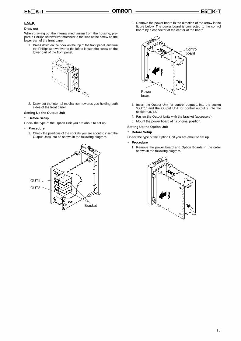
E5EKDraw-outWhen drawing out the internal mechanism from the housing, pre-pare a Phillips screwdriver matched to the size of the screw on thelower part of the front panel.
1. Press down on the hook on the top of the front panel, and turnthe Phillips screwdriver to the left to loosen the screw on thelower part of the front panel.
2. Draw out the internal mechanism towards you holding bothsides of the front panel.
Setting Up the Output Unit
• Before Setup
Check the type of the Option Unit you are about to set up.
• Procedure
1. Check the positions of the sockets you are about to insert theOutput Units into as shown in the following diagram.
OUT2
OUT1
Bracket
2. Remove the power board in the direction of the arrow in thefigure below. The power board is connected to the controlboard by a connector at the center of the board.
Powerboard
Controlboard
3. Insert the Output Unit for control output 1 into the socket“OUT1” and the Output Unit for control output 2 into thesocket “OUT2.”
4. Fasten the Output Units with the bracket (accessory).
5. Mount the power board at its original position.
Setting Up the Option Unit
• Before Setup
Check the type of the Option Unit you are about to set up.
• Procedure
1. Remove the power board and Option Boards in the ordershown in the following diagram.
E5K-T E5K-T
16
2. Insert the Option Unit into the socket for option 1. Thefollowing diagram shows the relationship between OptionUnit and mounting position.
Option 1E53-AKB: Event inputs 1/2E53-AK01: RS-232CE53-AK02: RS-422E53-AK03: RS-485E53-AKF: Transfer output
3. Mount the Option Board and the power board in the ordershown.
Mounting1. Insert the E5EK-T Controller into the mounting hole in the
panel.
2. Fit the mounting bracket (accessory) into the fixing slots onthe top and bottom of the rear case.
3. Tighten the mounting bracket screws alternately a little at atime until the ratchet starts to slide.
Setting Up the T erminal CoverFasten the Terminal Covers (E53-COV0809) to protect terminals.
E5AK-VV2-500 Controller is provided with Terminal Covers.
Use E53-COV09 for terminals 1 to 10, and E53-COV08 for termi-nals 11 to 33.
Fasten the Terminal Covers as follows by using the snap pins.
E5AK-T
E53-COV08
To remove the Terminal Covers, pull the edges of the snap pins.
E5K-T E5K-T
17
E5CKDraw-outDraw out the internal mechanism from the housing.
1. Press in both of the hooks on the left and right sides of thefront panel to unlock the internal mechanism from thehousing.
2. Draw out the internal mechanism towards you holding bothsides of the front panel.
Setting Up the Output Unit
• Procedure
1. Two rectangular holes for slotting are provided on the powerboard (on right side of Controller). Fit the two protrusions onthe Output Unit into these two holes.
2. With the Output Unit fitted into the power board, fit the OutputUnit into the connector on the control board (on left side ofController).
Setting Up the Option Unit
• Procedure
1. Place the Controller with its bottom facing up, and fit the boardhorizontally into the connector on the power board (on rightside of Controller).
2. With the power board connected, fit the board vertically intothe connector on the control board (on left side of Controller).
Mounting1. Insert the E5EK-T Controller into the mounting hole in the
panel.
2. Push the adapter along the Controller body from the terminalsup to the panel, and fasten temporarily.
3. Tighten the two fixing screws on the adapter. When tighteningscrews, tighten the two screws alternately keeping the torqueto approximately 0.29 to 0.39 N m, or 3 to 4 kgf cm.
Adapter
Panel
Waterproof packing
Setting the Input T ype JumperSet the jumper to one of temperature input, voltage input or currentinput matched to the type of sensor connected to the input terminal.
I : Current input V : Voltage input
TC/PT : Temperature input
The input type jumper is factory-set to “TC/PT (temperature input).”
When you disconnect or insert the input type jumper, do not hold itdirectly by its pins.
When you have finished setting the input type jumper, insert theinternal mechanism back into the housing.
To do this, push in the internal mechanism until you hear the hookson the front panel snap into place.
E5K-T E5K-T
18
DimensionsNote: All units are in millimeters unless otherwise indicated.
96 x 96
91 x
91
110 min.
44.8
x 4
4.8
53 x 53
120 min.
E5AK
E5EK
Panel Cutouts
Note: 1. Recommended panel thickness is 1 to 8 mm.
2. Maintain the specified vertical and horizontalmounting space between each Unit. Units mustnot be closely mounted vertically or horizontally.
Panel Cutouts
Note: 1. Recommended panel thickness is 1 to 8 mm.
2. Maintain the specified vertical and horizontalmounting space between each Unit. Units mustnot be closely mounted vertically or horizontally.
E5CK Panel Cutouts
60 min.
120 min.
60 min.
65 min.
Note: 1. Recommended panel thickness is 1 to 5 mm.
2. Maintain the specified vertical and horizontalmounting space between each Unit. Units mustnot be closely mounted vertically or horizontally.
TRSF: Transfer outputEV1 to 4: Event inputPTMR: Potentiometer
100-240 VAC24 VDC/AC
SOURCE
TRSF: Transfer outputEV1/2: Event inputPTMR: Potentiometer
SOURCE
E5AK-T E5EK-T
100-240 VAC24 VDC/AC
E5CK-T
5
4
3
2
1
10
9
8
7
613 14
11 12
OUT1
OUT2
SUB1IN
SOURCE
EV1RS232CRS485TRSF
TRSF: Transfer outputEV1: Event input
100-240 VAC24 VDC/AC
E5K-T E5K-T
21
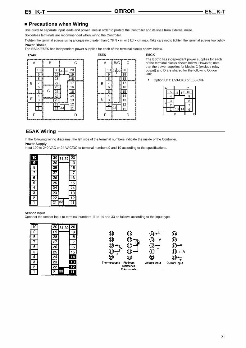
Precautions when WiringUse ducts to separate input leads and power lines in order to protect the Controller and its lines from external noise.
Solderless terminals are recommended when wiring the Controller.
Tighten the terminal screws using a torque no greater than 0.78 N m, or 8 kgf cm max. Take care not to tighten the terminal screws too tightly.Power BlocksThe E5AK/E5EK has independent power supplies for each of the terminal blocks shown below.
10987654321
30292827262524232221
20191817161514131211
31 32
33
A B C
B
F D
C
E
10987654321
20191817161514131211
21 22
23
A B/C C
B
F D
E
E5AK E5EKThe E5CK has independent power supplies for eachof the terminal blocks shown below. However, notethat the power supplies for blocks C (exclude relayoutput) and D are shared for the following OptionUnit.
• Option Unit: E53-CKB or E53-CKF
A C54321
109876
C
D B
11 12
13 14
E5CK
E5AK WiringIn the following wiring diagrams, the left side of the terminal numbers indicate the inside of the Controller.Power SupplyInput 100 to 240 VAC or 24 VAC/DC to terminal numbers 9 and 10 according to the specifications.
Sensor InputConnect the sensor input to terminal numbers 11 to 14 and 33 as follows according to the input type.
E5K-T E5K-T
22
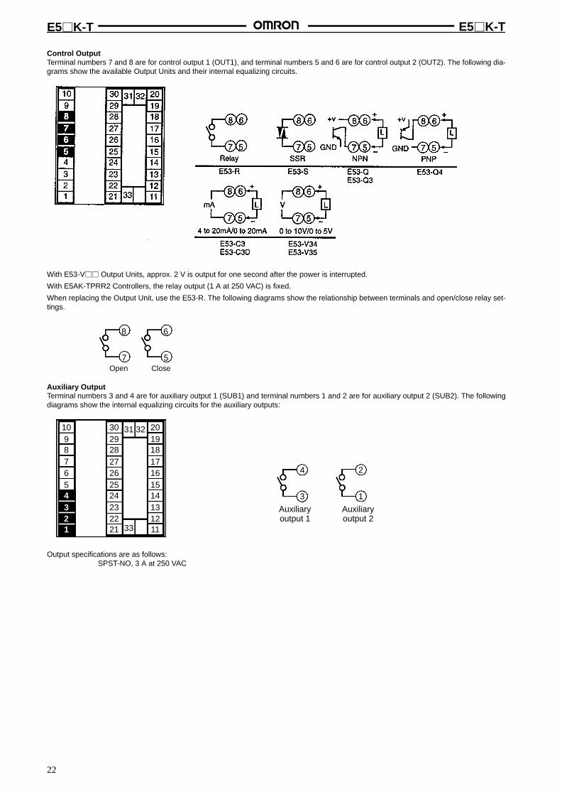
Control OutputTerminal numbers 7 and 8 are for control output 1 (OUT1), and terminal numbers 5 and 6 are for control output 2 (OUT2). The following dia-grams show the available Output Units and their internal equalizing circuits.
With E53-V Output Units, approx. 2 V is output for one second after the power is interrupted.
With E5AK-TPRR2 Controllers, the relay output (1 A at 250 VAC) is fixed.
When replacing the Output Unit, use the E53-R. The following diagrams show the relationship between terminals and open/close relay set-tings.
8
7Open
6
5Close
Auxiliary OutputTerminal numbers 3 and 4 are for auxiliary output 1 (SUB1) and terminal numbers 1 and 2 are for auxiliary output 2 (SUB2). The followingdiagrams show the internal equalizing circuits for the auxiliary outputs:
10987654321
30292827262524232221
20191817161514131211
31 32
33
4
3
2
1
Auxiliaryoutput 1
Auxiliaryoutput 2
Output specifications are as follows:SPST-NO, 3 A at 250 VAC
E5K-T E5K-T
23
CT Input/PotentiometerWhen using the HBA function on the E5AK-AA2 Controller, connect CT input (CT) to terminal numbers 15 to 17. When monitoring the valveopening on the E5AK-PRR2 Controller, connect the potentiometer (PTMR) to terminal numbers 15 to 17. Connect each of these inputs asfollows:
10987654321
30292827262524232221
20191817161514131211
31 32
33
17
16
15
17
16
15C
W
O
CT
CT input Potentiometer
Event InputConnect event inputs 1 and 2 (EV1/2) to terminal numbers 18 to 20, and event events 3 and 4 (EV3/4) to terminal numbers 24 to 26. However,note that terminal numbers 18 to 20 cannot be used on Controllers with a communications function. Connect the event inputs as follows:
10987654321
30292827262524232221
20191817161514131211
31 32
33
20
19
18
26
25
24
+
+
–Event input 1 and 2 Event input 3 and 4
EV1
EV2
COM
EV3
EV4
COM
+
+
–
Terminals 18 and 24 (COM) are connected internally.
Use event inputs under the following conditions:
Contact input ON: 1 kΩ max.OFF: 100 kΩ min.
No-contact input ON: Residual voltage 1.5 V max., OFF: Leakage current 0.1 mA max.
Polarities during no-contact input are as follows:
20
19
18
26
25
24
+
+
–Event input 1 and 2 Event input 3 and 4
EV1
EV2
COM
EV3
EV4
COM
+
+
–
E5K-T E5K-T
24
Transfer OutputConnect transfer output (TRSF) to terminal numbers 29 and 30. The internal equalizing circuit for transfer output is as follows:
30
29
4 to 20mA L
+
–
Transfer output specifications are as follows: 4 to 20 mA DC, Permissible load impedance: 600 Ω max., Resolution: Approx. 2,600
CommunicationsTerminal numbers 18 to 20, 31 and 32 can be used only on Controllers with Communications Units (E53-AK01/02/03). For details on wiring,refer to Chapter 6, Using the Communications Function in the E5AK-T/E5EK-T/E5CK-T User’s Manual (H88/H89/H90).
E5EK WiringIn the following wiring diagrams, the left side of the terminal numbers indicate the inside of the Controller.Power SupplyInput 100 to 240 VAC or 24 VAC/DC to terminal numbers 9 and 10 according to the specifications.
Sensor InputConnect the sensor input to terminal numbers 11 to 14 and 23 as follows according to the input type.
E5K-T E5K-T
25
Control OutputTerminal numbers 7 and 8 are for control output 1 (OUT1), and terminal numbers 5 and 6 are for control output 2 (OUT2). The following dia-grams show the available Output Units and their internal equalizing circuits.
With E53-V Output Units, approx. 2 V is output for one second after the power is interrupted.
With E5EK-TPRR2 Controllers, the relay output (1 A at 250 VAC) is fixed.
When replacing the Output Unit, use the E53-R. The following diagrams show the relationship between terminals and open/close relay set-tings.
8
7Open
6
5Close
Auxiliary OutputTerminal numbers 3 and 4 are for auxiliary output 1 (SUB1) and terminal numbers 1 and 2 are for auxiliary output 2 (SUB2). The followingdiagrams show the internal equalizing circuits for the auxiliary outputs:
10987654321
20191817161514131211
21 22
23
4 2
1
Auxiliaryoutput 1
Auxiliaryoutput 2
3
Output specifications are as follows:SPST-NO, 3A at 250 VAC
E5K-T E5K-T
26
CT Input/PotentiometerWhen using the HBA function on the E5EK-AA2 Controller, connect CT input (CT) to terminal numbers 15 to 17. When monitoring the valveopening on the E5EK-TPRR2 Controller, connect the potentiometer (PTMR) to terminal numbers 15 to 17. Connect each of these inputs asfollows:
10987654
321
20191817161514
131211
21 22
23
17
16
15
17
16
15
O
W
C
CT input Potentiometer
For details on CT inputs, refer to Appendix, About Current Transformer in the E5AK-T/E5EK-T/E5CK-T User’s Manual (H88/H89/H90). Fordetails on the potentiometer, refer to the Instruction Manual for the valve connected to the Controller. The variable resistance range is 100 Ω to2.5 kΩ.Event InputConnect event inputs 1 and 2 (EV1/2) to terminal numbers 18 to 20. However, note that terminal numbers 18 to 20 cannot be used on Control-lers with a communications function. Connect the event inputs as follows:
109
87654321
20191817161514131211
21 22
23
20
19
18
Event input 1 and 2
EV1
EV2
COM
+
+
–
Use event inputs under the following conditions:
Contact input ON: 1 kΩ max., OFF: 100 kΩ min.
No-contact input ON: Residual voltage 1.5 V max., OFF: Leakage current 0.1 mA max.
Polarities during no-contact input are as follows:
20
19
18
Event input 1 and 2
EV1
EV2
COM
+
+
–
Transfer OutputConnect transfer output (TRSF) to terminal numbers 21 and 22. The internal equalizing circuit for transfer output is as follows:
21
22
4 to 20mA L
+
–
E5K-T E5K-T
27
Transfer output specifications are as follows:4 to 20 mA DC, Permissible load impedance: 600 Ω max., Resolution: Approx. 2,600
CommunicationsTerminal numbers 18 to 22 can be used only on Controllers with Communications Units (E53-AK01/02/03). For details on wiring, refer to Chap-ter 6, Using the Communications Function in the E5AK-T/E5EK-T/E5CK-T User’s Manual (H88/H89/H90).
E5CK Wiring
Power SupplyInput 100 to 240 VAC or 24 VAC/DC to terminal numbers 4 and 5 according to the specification.
5
4
3
2
1
10
9
8
7
613 14
11 12
Sensor InputConnect the input to terminal numbers 6 to 8 as follows according to the input type.
8
7
6
8
7
6
8
7
6
8
7
6
-
+
-
+
-
+
V mA
TC ⋅ PT V I
Thermocouple Platinum resistancethermometer
Voltage input Current input
5
4
3
2
1
10
9
8
7
613 14
11 12
Match the inputs with the internal jumper settings for each input type. For thermocouple or platinum resistance thermometer inputs, set theinputs to a common position (TC/PT) as the temperature input.
Control OutputTerminal numbers 11 and 12 are for control output 1 (OUT1). The five output types and internal equalizing circuits are available according to theOutput Unit.
5
4
3
2
1
10
9
8
7
613 14
11 12 11
12
11
12
L
11
12
L
11
12
L
11
12
L
E53-R4R4 E53-Q4R4E53-Q4Q4
E53-Q4HR4E53-Q4HQ4H
E53-V44R4 E53-C4R4E53-C4DR4
NPN PNP 0 to 10 V 4 to 20mA
+v+
-
+
-
+
-
+
-GND
mA
Relay
V
+v
GND
Terminal numbers 9 and 10 are for control output 2 (OUT2). The three output types and internal equalizing circuits are available according to theOutput Unit.
Auxiliary Output 1Terminal numbers 2 and 3 are for auxiliary output 1 (SUB1).
The internal equalizing circuit for auxiliary output 1 is as follows:
5
4
3
2
1
10
9
8
7
613 14
11 12 3
2
Relay specifications are as follows:SPST-NO, 250 VAC, 1 A
OptionTerminal numbers 1, 13, and 14 are valid only when the Option Unit is set in the Controller.
The following four connections are possible depending on the model of the Option Unit.
5
4
3
2
1
10
9
8
7
613 14
11 12 13
14
1
13
14
1
13
14
1
13
14
1
SD
RD
SG
A
B
+
–
4 to 20mA
E53-CK01
RS-232C
E53-CK03
RS-485
E53-CKB E53-CKF
Event input Transfer output
Use event inputs under the following conditions:
Contact input ON: 1 kΩ max., OFF: 100 kΩ min.
No-contact input ON: residual voltage 1.5 V max., OFF: leakage current 0.1 mA max.
The polarity for no-contact input is as follows:
13
14
1
+
–
Transfer output specifications are as follows:4 to 20 mA DC, load: 500 Ω max., resolution approx. 2,600
E5K-T E5K-T
29
After Turning Power ONDetermine the I/O specifications of the Digital Controller in setupmode.
Setup Mode
Power ON
Process value
1 s min.
1 s min.
Input type
Temperature input Current/Voltage input
°C/°Fselection
Scalingupper limit
Scalinglower limit
Decimal point
Parameter initialize
From next column To next column
prgn
To previous column From previous column
Control output 1assignment (Notdisplayed by theE5K-TPRR2)
Control output 2assignment (Notdisplayed by theE5K-TPRR2)
Auxiliary output 1assignment
Outputassignment
Auxiliary output 2assignment (Notdisplayed by theE5CK)
Alarm 1 type
Alarm 1open inalarm
Alarm 2 typeAlarm type
Alarm 2open inalarm
Alarm1, 2, or3 is notset.
Alarm 3 type
Alarm 3open inalarm
Direct/Reverseoperation
Note: Parameter InitializeParameter initialization sets all parameters to default val-ues except for the input type, scaling upper limit, scalinglower limit, decimal point, and °C/°F selection parameters.
E5K-T E5K-T
30
Specifications Input Type
Set the code according to the following table. Default is “2: K1 ther-mocouple.”
Platinum Resistance Thermometer
Set Input typeSetvalue
Input type
0 JPt100 –199.9 to 650.0 (°C)/–199.9 to 999.9 (°F)
Platinumresistanceth t
1 Pt100 –199.9 to 650.0 (°C)/–199.9 to 999.9 (°F)
thermometer
2 K1 –200 to 1,300 (°C)/–300 to 2,300 (°F)
Thermocouple
3 K2 0.0 to 500.0 (°C)/0.0 to 900.0 (°F)
4 J1 –100 to 850 (°C)/–100 to 1,500 (°F)
5 J2 0.0 to 400.0 (°C)/0.0 to 750.0 (°F)
6 T –199.9 to 400.0 (°C)/–199.9 to 700.0 (°F)
7 E 0 to 600 (°C)/0 to 1,100 (°F)
8 L1 –100 to 850 (°C)/–100 to 1,500 (°F)
9 L2 0.0 to 400.0 (°C)/0.0 to 750.0 (°F)
10 U –199.9 to 400.0 (°C)/–199.9 to 700.0 (°F)
11 N –200 to 1,300 (°C)/–300 to 2,300 (°F)
12 R 0 to 1,700 (°C)/0 to 3,000 (°F)
13 S 0 to 1,700 (°C)/0 to 3,000 (°F)
14 B 100 to 1,800 (°C)/300 to 3,200 (°F)
15 W 0 to 2,300 (°C)/0 to 4,100 (°F)
16 PLII 0 to 1,300 (°C)/0 to 2,300 (°F)
17 4 to 20 mA Current input
18 0 to 20 mA
19 1 to 5 V Voltage input
20 0 to 5 V
21 0 to 10 V
Output AssignmentsThirteen output functions are available. Allocate these functions tothe control outputs 1 and 2 and auxiliary outputs 1 and 2.
There are some limitations on some output function allocations.
Output function types and allocation limitations are as described inthe following.
Identical output functions cannot be allocated doubly to the controloutput 1 or 2 and auxiliary output 1 or 2.
Standard ModelsAssignment Destination
Control Output Auxiliary OutputDestination
Output Function 1 2 1 2
Control output (heat)(see note 1)
Yes Yes No No
Control output (cool)(see note 1)
Yes Yes No No
Alarm 1 Yes Yes Yes Yes
Alarm 2 Yes Yes Yes Yes
Alarm 3 Yes Yes Yes Yes
HBA (see notes 1, 2) Yes Yes Yes Yes
LBA (see note 1) Yes Yes Yes Yes
Time signal 1 Yes Yes Yes Yes
Time signal 2 Yes Yes Yes Yes
Program end Yes Yes Yes Yes
Stage output (see note 1)
Yes Yes Yes Yes
Error 1 : Input error No No Yes Yes
Error 2 : A/D convertorerror
No No Yes Yes
Note: 1. Assignment is not possible with the control valve controltype.
2. Heater burnout alarm is not available for the E5CK.
Position-proportional ModelsPosition-proportional-type Controllers support nine output func-tions. These are assigned to auxiliary outputs 1 and 2.
Restrictions on assignment destinations are placed on some of theoutputs. The following table shows where outputs may be assignedto.
Assignment Destination
Control Output Auxiliary OutputDestination
Output Function 1 2 1 2
Alarm 1 No No Yes Yes
Alarm 2 No No Yes Yes
Alarm 3 No No Yes Yes
Time signal 1 No No Yes Yes
Time signal 2 No No Yes Yes
Stage output No No Yes Yes
Program end output No No Yes Yes
Error 1 : Input error No No Yes Yes
Error 2 : A/D convertererror
No No Yes Yes
With control output (cool), the conditions for switching from stan-dard control to heating and cooling control are reached when theoutput function is assigned at the cooling side during heating andcooling control.
In other words, heating and cooling control is carried out when con-trol output (cool) is assigned, and standard control is carried outwhen output is not assigned.
E5K-T E5K-T
31
LBAThe LBA (loop break alarm) function is available when it is assignedas an output. The LBA function is not available when a memory orA/D converter error results.
LBA is a function for determining that an error has occurred some-where on the control loop and outputting an alarm when the processvalue does not change with the manipulated variable at a maximumor minimum state. Accordingly, the LBA function can be used as ameans for detecting a malfunctioning control loop.
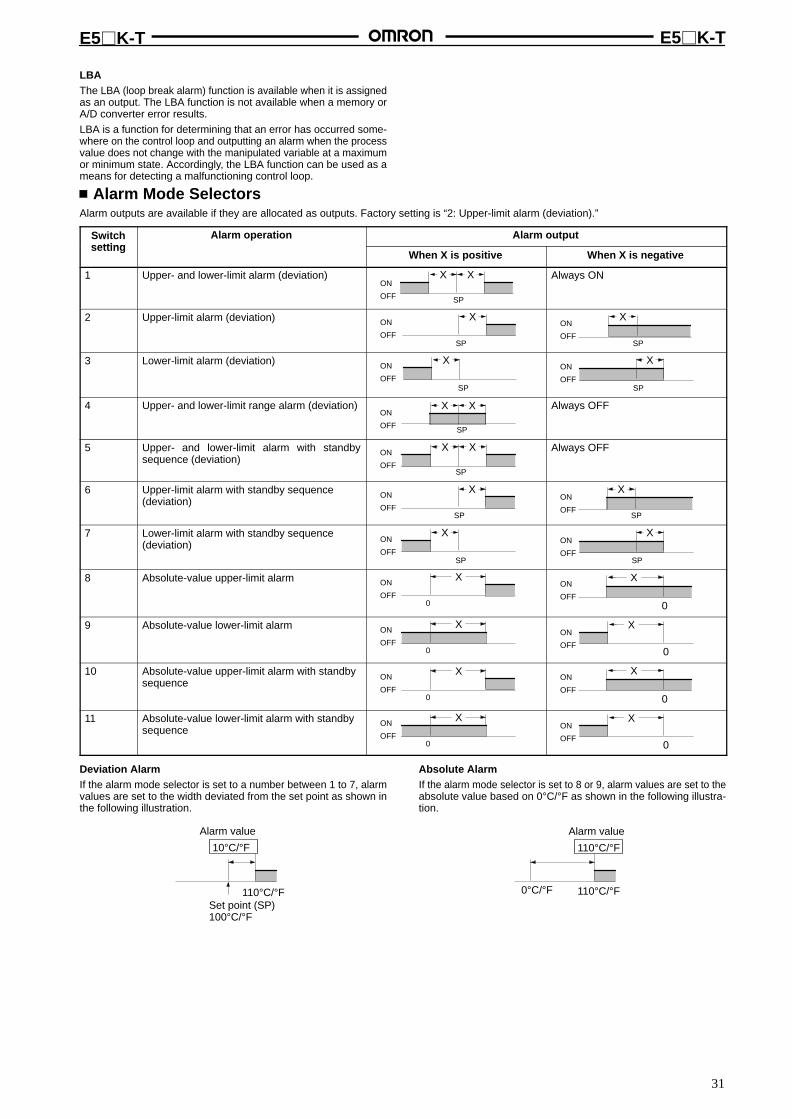
Alarm Mode SelectorsAlarm outputs are available if they are allocated as outputs. Factory setting is “2: Upper-limit alarm (deviation).”
Switchsetting
Alarm operation Alarm outputsetting
When X is positive When X is negative
1 Upper- and lower-limit alarm (deviation) X XON
OFF SP
Always ON
2 Upper-limit alarm (deviation) X
SP
ON
OFF
X
SP
ON
OFF
3 Lower-limit alarm (deviation) X
SP
ON
OFF
X
SP
ON
OFF
4 Upper- and lower-limit range alarm (deviation) X X
SP
ON
OFF
Always OFF
5 Upper- and lower-limit alarm with standbysequence (deviation)
X X
SP
ON
OFF
Always OFF
6 Upper-limit alarm with standby sequence(deviation)
X
SP
ON
OFF
X
SP
ON
OFF
7 Lower-limit alarm with standby sequence(deviation)
X
SP
ON
OFF
X
SP
ON
OFF
8 Absolute-value upper-limit alarm X
0
ON
OFF0
XON
OFF
9 Absolute-value lower-limit alarm X
0
ON
OFF0
XON
OFF
10 Absolute-value upper-limit alarm with standbysequence
X
0
ON
OFF0
XON
OFF
11 Absolute-value lower-limit alarm with standbysequence
X
0
ON
OFF0
XON
OFF
Deviation AlarmIf the alarm mode selector is set to a number between 1 to 7, alarmvalues are set to the width deviated from the set point as shown inthe following illustration.
Set point (SP)100°C/°F
Alarm value
10°C/°F
110°C/°F
Absolute AlarmIf the alarm mode selector is set to 8 or 9, alarm values are set to theabsolute value based on 0°C/°F as shown in the following illustra-tion.
0°C/°F
Alarm value
110°C/°F
110°C/°F
E5K-T E5K-T
32
Close in Alarm/Open in AlarmWhen the Controller is set to “close in alarm,” the status of the alarmoutput function is output as it is. When set to “open in alarm,” the sta-tus of the alarm output function is output inverted.
Condition Alarm Output Output LED
Close inl
ON ON LitC osealarm OFF OFF Not lit
Open inl
ON OFF LitO ealarm OFF ON Not lit
Alarm type and close in alarm (normally open)/open in alarm (nor-mally close) can be set independently from each alarm.
Close in alarm/Open in alarm is set in the “alarm 1 to 3 open inalarm” parameters (setup mode). Factory setting is “close in alarm”[ no ].
Parameter Operations Parameter Operation List
Switching to modes other than manual or protect mode is carried out using the mode selection in the menu display.
The figure below shows all parameters in the order that they are displayed. Some parameters are not displayed depending on the protect modesetting and conditions of use.
Power ON
Level 0 mode
Level 1 mode
Level 2 mode
Setup mode
Expansion mode
Option mode
Calibration mode
1 second min.
Program mode
Protect mode
Manual mode
1 second min.
1 second min. 1 second min.
1 second min.
1 second min.
1 second min.
1 second min.
1 second min.
1 second min.
1 second min.
1 second min.
1 second min.
Parameters and MenusNote: For more details on the functions of each part and display contents, refer to the E5AK-T/E5EK-T/E5CK-T User’s Manual
(H88/H89/H90).
Protect Mode The protect function is for preventing unwanted modification of parameters and switching betweenrun and reset operation or auto and manual operation.
Manual Mode In this mode, the Controller can be switched to manual operation. The manipulated variable can bemanipulated manually only in this mode.
E5K-T E5K-T
33
Level 0 Mode Set the Controller to this mode during normal operation. In this mode, you can change the set pointand pattern during operation, and execute step operation (e.g. advance). You can only monitor (notchange) the process value, step No., standby time, pattern elapsing time, pattern execution count,and manipulated variable.
Program Mode This is the programming mode. In this mode, you can set the number of steps used in each pattern,pattern execution count, alarm values, set points for each step, step time, and time signals for twosteps.
Level 1 Mode This is the main mode for adjusting control. In this mode, you can execute AT (auto-tuning), and setup the control period, PID parameters and heater burnout alarm (HDA) conditions.
Level 2 Mode This is the auxiliary mode for adjusting control. In this mode, you can set the parameters for limitingthe manipulated variable, switch between the remote and local modes, and set the loop break alarm(LBA), alarm hysteresis, and the digital filter value of inputs.
Setup Mode This is the mode for setting the basic specifications. In this mode, you can set parameters that mustbe checked or set before an operation such as the input type, scaling, output assignments, anddirect/reverse operation.
Expansion Mode This is the mode for setting expanded functions. In this mode, you can set SP setting limiter, switch-ing between 2-PID control or ON/OFF control, program time unit, selection of step time/rate of rise,time unit of ramp rise rate, and the time for automatic return to the monitoring display.
Option Mode This is the mode for setting optional functions. You can select this mode only when an Option Unit ismounted in the Controller. In this mode, you can set the communications conditions, transfer outputand event input parameters to match the type of Option Unit mounted in the Controller. Heater burn-out alarm function and position-proportional travel time are also found in this mode.
Calibration Mode This mode is provided so that the user can calibrate inputs and output. When calibrating input, theselected input type is calibrated. Whereas, transfer output can be calibrated only when the Commu-nications Unit (E53-AKF) is set in the Controller.
E5K-T E5K-T
34
Parameter OperationRefer to the E5AK-T/E5EK-T/E5CK-T User’s Manual (H88/H89/H90) for each parameter and the calibration mode in detail.
Refer to page 13 for the setting in detail.
Level 0 Mode
Process ValueSet Point
Pattern Number(With E5CK, this display appears when more thantwo patterns are used.)
Step Number Monitor
Hold
Advance
Standby Time (displays remaining time) Monitor
Pattern Elapsing Time Monitor
Pattern Execution Count Monitor
MV Monitor (heating)
(Control Valve Control)
(Heating/Cooling Control)
MV Monitor(Cooling)
MV Valve Opening
MV
Time
Time
Number of times
Measuredvalue
Protect ModeUnder this mode, key operations are invalidated for the Auto/Manu-al and Run/Reset.
Press 1 s min.simultaneously.
Security
Key protect
To level 0 Press 1 s min.simultaneously.
RUN/RST
RUN/RST
0
SecurityBefore starting operation, apply key protection to the parametersthat will not be changed during operation in order to prevent any ac-cidental parameter changes.
Depending on the set values for the Security parameter (protectmode), ranges of parameter application will be restricted. The fol-lowing table shows relationship between the set values and thescope of protection.
Mode Set value
0 1 2 3 4 5 6
Calibration Yes No No No No No No
Option Yes Yes No No No No No
Expansion Yes Yes No No No No No
Setup Yes Yes No No No No No
Level 2 Yes Yes Yes No No No No
Level 1, 0 Yes Yes Yes Yes No No No
Program Yes Yes Yes Yes Yes No No
Level 0 Yes Yes Yes Yes Yes Yes *
Note: *Only the “Process Value/Set Point” parameter display ispossible.
When the set value is “0,” protection will not be applied.
When the set value is “5,” only the parameter in the level 0 mode canbe used and not possible to change to the menu screen.
When the set value is “6,” only the “Process Value/Set Point” can bemonitored.
The default setting is “1.”
Manual Mode
Process valueManipulated variable/Valve opening monitor
MANU indicator
+
+
Press simul-
taneously 1 s
min.
Press simultaneously
1 s min.
E5K-T E5K-T
35
Program Mode
Pattern numberSynchronized with with the patternnumber of level 0 mode.
Step numberChanged to the ramp setting method. Refer to theOperation Manual for the ramp setting method.
Time setting methodTarget SP 0
Step 0 SP
Ramp Rate 0
Step 0 time
Soak time 0
Target SP 7Step 7 SP
Ramp rate 7Step 7 time (see note)
Soak time 7 (max.)
Time Setting Method
Set the number of steps to be used beginning with step 0 (e.g., step0 SP, step 0 time, step 1 SP, and step 1 time).
The step target value can be set within a range between thelower and upper target value limits. The default value is zero.
The step time can be set within a range between 0.00 and 99.59(in hr and min or min and s). The default value is 0.00.
Step 0 Step 1 Step 3Step 2
Step 0 time Step 1 time Step 2 time Step 3 time
A: Step 0 and step 3 SPB: Step 1 and step 2 SP
Time
Step 0 is flat as shown in the above graph. Set step 0 to 0.00 so thatstep 1 will be the actual first step when writing ramp-start programs.
Note: Up to step 15 (i.e., a total of 16 steps) canbe set in the time setting method.
Time signal 1 enabled step
Time signal 1 ON time
Time signal 1 OFF time
Time signal 2 enabled step
Time signal 2 ON time
Time signal 2 OFF time
Time Signal
Two types of time signal patterns can be set in each pattern.
Time signal output
ON time Time
OFF time
Two types of time signal timers are available (i.e., ON-time and OFF-time use), eachof which starts with the edge of the step.
The output is ON from the moment the ON time elapses until the OFF time elapses.
Set the step so that the time signal is triggered by the time signal 1/2 enabled stepparameters. The default is step 0.
Set the ON/OFF timing with the timing signal 1/2 ON-time and time signal 1/2OFF-time parameters in Program mode.
ON Conditions
If the ON time is shorter than the OFF time, the signal will be reset or ON after the ONtime elapses until the next pattern starts.
The signal is not ON if there is no difference in period between the ON time and OFF time.
If ADVANCE is executed while the time signal setting step is executed, the time equiv-alent to the setting step will be deemed to have elapsed. In the above graph, for exam-ple, the signal is ON from the edge of the next step until the OFF time elapses.
Pattern execution count
Alarm value 1 (displayed only if the alarm is allocated.)
Alarm value 2 (displayed only if the alarm is allocated.)
Alarm value 3 (displayed only if the alarm is allocated.)
E5K-T E5K-T
36
Level 1 Mode
AT Execute/Cancel
Proportional BandAvailable if the Controller is in 2-PID control.
Integral TimeAvailable if the Controller is in 2-PID control.
Derivative TimeAvailable if the Controller is in 2-PID control.
For heating/cooling control
For E5K-PRR2
Cooling CoefficientUsed with the Controller is inheating and cooling control.
Dead BandUsed with the Controller is inheating and cooling control.
Manual Reset ValueAvailable when the integral time parameterof the Controller in standard control is “0.”
Hysteresis (Heat)Available when the Controller is inON/OFF control.
For heating/cooling controlHysteresis (Cool)Available when the Controller is inON/OFF control
Control Period (Heat)Available when the Controller has a relay orvoltage output, or is in 2-PID control.
For heating/cooling controlControl Period (Cool)Available when the Controller has a relayor voltage output, or is in 2- PID control.
Current value
Heater Current MonitorAvailable when the heaterburnout alarm is assigned.
Heater Burnout DetectionAvailable when the heaterburnout alarm is assigned.
Position-proportionaldead band
Level 2 Mode
Remote/LocalUsed for thecommunications function.
LBA Detection TimeAvailable when the LBA (loop breakalarm) is assigned as an output.Unavailable to the E5K-PRR2.
MV at Reset
MV at PV Error
MV Upper LimitUnavailable to theE5K-PRR2.
MV Lower LimitUnavailable to theE5K-PRR2.
MV Change Rate Limit
Input Digital Filter
Alarm 1 HysteresisAvailable only when the alarmoutput 1 is assigned.
Alarm 2 HysteresisAvailable only when the alarmoutput 2 is assigned.
Alarm 3 HysteresisAvailable only when the alarmoutput 3 is assigned.
Input Shift Upper LimitAvailable if the input type is athermocouple or platinum resistancethermometer.
Input Shift Lower LimitAvailable if the input type is athermocouple or platinum resistancethermometer.
(See Input Shift)
For E5K-PRR2
Open/Close Hysteresis
Standby Time
Input ShiftWhen temperature input is selected, scaling is not required. This isbecause input is treated as the “temperature” as it is matched to theinput type. However, note that the upper- and lower-limit values ofthe sensor can be shifted. For example, if both the upper- and lower-limit values are shifted by 1.2°C, the process value (before shift) isregarded as 201.2°C after shift when input is 200°C before shift.
To set the input shift, set shift values in the “input shift upper limit”and “input shift lower limit” parameters (level 2 mode).
Temperature
Upper limit
Upper-limit compensation value
Aftercompensation
Before compensation
Lower limitLower-limitcompensation value
Input (% of full scale)
E5K-T E5K-T
37
Expansion Mode
Set Point UpperLimit
Set PointLower Limit
PID/ON/OFF(not displayed for control valve control)
αAvailable if the Controller is in 2-PIDcontrol.
AT Calculated GainAvailable if the Controller is in 2-PIDcontrol.
AT HysteresisAvailable if the Controller is in 2-PIDcontrol.
LBA Detection WidthAvailable only when the LBA (loop breakalarm) function is assigned.Unavailable to the E5K-PRR2.
Operation at Power ON
End condition
Automatic Return of Display Mode
Number of Patterns (Displayed for E5CK.)
Program Time Unit
Stop Time/Rate of Rise Programming
Time Unit of Ramp Rate (used for Rate of Rise Setting)
PV Start (used for setting time)
Wait Width (available for E5AK or E5EK.)
Alarm During Ramp Step Enable
Run All Enable (with E5CK, this display appearswhen more than two patterns are used.)
Option Mode
Event Input Assignment 1Available for the event input function.
Event Input Assignment 2Available for the event input function.
Event Input Assignment 3Available for the event input function.
Event Input Assignment 4Available for the event input function.
Communication Stop BitUsed when the communications function is being used.
Communication Data LengthUsed when the communications function is being used.
Communication ParitySet when the communications function is being used.
Communication Baud RateSet when the communications function is being used.
Communication Unit No.Set when the communications function is being used.
Transfer Output TypeSet when the transfer output function is being used.
Transfer Output Upper LimitSet when the transfer output function is being used.
Transfer Output Lower LimitSet when the transfer output function is being used.
For E5K-PRR2
Motorcalibration
Travel time
PV deadband
HBA latch
E5K-T E5K-T
38
How to Use the Error DisplayWhen an error has occurred, the No.1 display alternately indicates error codes together with the current display item.This section describes how to check error codes on the display, and the actions that must be taken to remedy the problem.
Input Error
Meaning Input is in error.
Action Check the wiring of inputs, disconnections, and shorts, and check the input type and the input typejumper connector.
Operation at Error For control output functions, output the manipulated variable matched to the setting of the “MV at PVerror” parameter (level 2 mode). Alarm output functions are activated when the upper limit isexceeded.
Memory Error
Meaning Internal memory operation is in error
Action First, turn the power OFF then back ON again. If the display remains the same, the E5K-T Control-ler must be repaired. If the display is restored to normal, the probable cause may be external noiseaffecting the control system. Check for external noise.
Operation at Error Control output functions turn OFF (2 mA max. at 4 to 20 mA output, and output equivalent to 0% incase of other outputs). Alarm output functions turn OFF.
A/D Converter Error
Meaning Internal circuits are in error.
Action First, turn the power OFF then back ON again. If the display remains the same, the E5K-T Control-ler must be repaired. If the display is restored to normal, the probable cause may be external noiseaffecting the control system. Check for external noise.
Operation at Error Control output functions turn OFF (2 mA max. at 4 to 20 mA output, and output equivalent to 0% incase of other outputs). Alarm output functions turn OFF.
Calibration Data Error
This error is output only during temperature input and is displayed for two seconds when the power isturned ON.
Meaning Calibration data is in error.
Action Must repair.
Operation at Error Both control output functions and alarm output functions are active. However, note that the readoutaccuracy is not assured.
Display Range Over
Meaning Though not an error, this is displayed when the process value exceeds the display range when thecontrol range (setting range ±10%) is larger than the display range (–1999 to 9999).
• When less than “–1999”
• When greater than “9999”
Operation Control continues, allowing normal operation.
E5K-T E5K-T
39
PrecautionsWARNING
Do not touch the terminals while the power is ON.This may cause an electric shock.
General PrecautionsBe sure to observe these precautions to ensure safe use.
• Do not use the product in places where explosive or flammablegases may be present.
• Never disassemble, repair or modify the product.
• Tighten the terminal screws properly.
• Use the specified size of solderless terminals for wiring.
• Use the product within the rated supply voltage.
• Use the product within the rated load.
• The life expectancy of the output relay varies considerablyaccording to its switching capacity and operating conditions. Besure to use the output relay within its rated load and electrical lifeexpectancy. If the output relay is used beyond its life expectancy,its contacts may become fused or burned.
Correct UseIf you remove the Controller from its case, never touch nor applyshock to the electronic parts inside.
Do not cover the E5K-T. (Ensure sufficient space around the Con-troller to allow heat radiation.)
Do not use the Controller in the following places:
• Places subject to icing, condensation, dust, corrosive gas(especially sulfide gas or ammonia gas).
• Places subject vibration and large shocks.
• Places subject to splashing liquid or oil atmosphere.
• Places subject to intense temperature changes.
• Places subject to heat radiation from a furnace.
Be sure to wire properly with correct polarity of terminals.
When wiring input or output lines to the Controller, keep the follow-ing points in mind to reduce the influence from inductive noise:
• Allow adequate space between the high voltage/current powerlines and the input/output lines.
• Avoid parallel or common wiring with high voltage sources andpower lines carrying large currents.
• Using separating pipes, ducts, and shielded line is also useful inprotecting the Controller, and its lines from inductive noise.
Cleaning: Do not use paint thinner or organic solvents. Use stan-dard grade alcohol to clean the product.
Use a voltage (100 to 240 VAC at 50/60 Hz, or 24 VDC). At powerON, the prescribed voltage level must be attained within twoseconds.
Allow as much space as possible between the Controller anddevices that generate a powerful high frequency (high-frequencywelders, high-frequency sewing machines, etc.) or surge. Thesedevices may cause malfunctions.
If there is a large power-generating peripheral device and any of itslines near the Controller, attach a surge suppressor or noise filter tothe device to stop the noise affecting the Controller system. In par-ticular, motors, transformers, solenoids and magnetic coils have aninductance component, and therefore can generate very strongnoise.
When mounting a noise filter on the power supply to the Controller,be sure to first check the filter’s voltage and current capacity, andthen mount the filter as close as possible to the Controller.
Use within the following temperature and humidity ranges:
• Temperature: –10°C to 55°C (with no icing or condensation)Humidity: 35% to 85% (with no icing or condensation)If the Controller is installed inside a control board, the ambienttemperature must be kept to under 55°C, including thetemperature around the Controller.If the Controller is subjected to heat radiation, use a fan to coolthe surface of the Controller to under 55°C.
Store within the following temperature and humidity ranges:
• Temperature: –25°C to 65°C (with no icing or condensation)Humidity: 35% to 85% (with no icing or condensation)
Never place heavy objects on, or apply pressure to the Controllerthat may cause it to deform and deteriorate during use or storage.
Avoid using the Controller in places near a radio, television set, orwireless installing. These devices can cause radio disturbanceswhich adversely affect the performance of the Controller.
MountingThe dimensions of the Digital Controller conform to DIN 43700.
Recommended panel thickness is 1 to 8 mm (1 to 5 mm for E5CK).
Mount the Unit horizontally.
ConnectionTo reduce inductive noise influence, the lead wires connecting theinput type to the Digital Controller must be separated from the powerlines and load lines.
Use the specified compensating conductors for thermocouples.Use lead wires having a small resistance for platinum resistancethermometers.
Connection ExampleWire the terminals of the Unit using solderless terminals.
The tightening torque applied to the terminal screws of the Unit mustbe approximately 0.78 N m or 8 kgf cm.
Use the following type of solderless terminals for M3.5 screws.
7.2 mm max.
7.2 mm max.
!
E5K-T E5K-T
40
SSRConnection Example of Digital Controller and SSR
+
–
+
–
Digital Controller
Voltage outputterminal (for driv-ing SSR)
Connectable
Load
HeaterPower supplyfor load
Power SSR
SSR
E5AK-T, E5EK-T
Digital Controller withVoltage Output(12 VDC, 40 mA max.)
See the following table.
E5CK
Digital Controller withVoltage Output(12 VDC, 20 mA max.)
INPUT LOAD
Model G3PA G3NH G3NA G3NE G3B
Appearance
SSRs connectedin parallel
E5AK/E5EK: 5 pcs.E5CK: 3 pcs.
E5AK/E5EK: 8 pcs.E5CK: 4 pcs.
E5AK/E5EK: 5 pcs.E5CK: 2 pcs.
E5AK/E5EK: 2 pcs.E5CK: 1 piece
E5AK/E5EK: 5 pcs.E5CK: 2 pcs.
Rated inputvoltage
5 to 24 VDC 5 to 24 VDC 5 to 24 VDC 12 VDC 5 to 24 VDC
Features Thin, monoblockconstruction withheat sink


![[E5] Thailand](https://static.documents.pub/doc/80x56/577cc72b1a28aba711a02f6f/e5-thailand.jpg)


