313
Digital Partyline User Guide Part Number: 399G229 Revision A Date 30 August 2017 User Guide

Digital Partyline User Guide
Part Number: 399G229 Revision A
Date 30 August 2017
User
Guide

Page 2
Document Reference
Clear-Com HelixNet Partyline User Guide
Part Number: 399G229 Revision: A
Legal Disclaimers
Copyright © 2017 HME Clear-Com Ltd.
All rights reserved.
Clear-Com, the Clear-Com logo, Clear-Com Concert and HelixNet are registered trademarks of HM Electronics, Inc.
The software described in this document is furnished under a license agreement
and may be used only in accordance with the terms of the agreement.
The product described in this document is distributed under licenses restricting its
use, copying, distribution, and decompilation/reverse engineering. No part of this
document may be reproduced in any form by any means without prior written authorization of Clear-Com, an HME Company.
This product is covered by U.S. Patent Nos. 8,311,085 and 8,553,865 and by
European Patent No. 2 176 987 B1.
Clear-Com Offices are located in California, USA; Cambridge, UK; Montreal,
Canada; and Beijing, China. Specific addresses and contact information can be found on Clear-Com’s corporate website:
www.clearcom.com
Clear-Com Contacts
Americas and Asia-Pacific Headquarters California, United States
Tel: +1.510.337.6600
Email: [email protected]
Europe, Middle East, and Africa Headquarters
Cambridge, United Kingdom Tel: +44 1223 815000
Email: [email protected]
China Office
Beijing Representative Office Beijing, P.R.China
Tel: +8610 65811360 / 65815577
Page 3
Contents
1 Introduction .......................................................................... 9
1.1 Important Safety instructions .................................................... 9
1.2 Methods of connection: system overview .................................. 11
1.3 Further information ................................................................ 15
2 Panels and Interfaces .......................................................... 16
2.1 Main Station/Remote Station: Front panel ................................. 16
2.2 HMS-4X Main Station: rear panel ............................................. 23
2.3 Remote Station rear panel ...................................................... 29
2.4 Speaker Station .................................................................... 33
2.5 HBP-2X Beltpack ................................................................... 41
2.6 HXII-BP-X4 Beltpack .............................................................. 46
3 Installing HelixNet Partyline ............................................... 53
3.1 Planning your HelixNet Partyline installation .............................. 54
3.2 Installing the Main Station/Remote Station ................................ 59
3.3 Installing the Speaker Station ................................................. 60
3.4 Installing the HBP-2X Beltpacks ............................................... 63
3.5 Installing the HXII-BP-X4 Beltpacks ......................................... 63
3.6 HelixNet infrastructure ........................................................... 65
3.7 Converting analogue Partylines to HelixNet ............................... 66
4 IP Network Structure .......................................................... 68
4.1 Network connections .............................................................. 68
4.2 Multiple Groups in the same IP Network .................................... 68
4.3 Link Local Environments ......................................................... 69
5 Configuring and managing the Main Station from front
menus ................................................................................. 72
5.1 Using the Menus .................................................................... 72
5.2 Configuring the Audio settings ................................................. 73
5.3 Selecting Station Settings ....................................................... 79
5.4 Configuring the Channel settings ............................................. 83
5.5 Configuring the Control I/O ..................................................... 85

Page 4
5.6 Configuring Module Settings .................................................... 87
5.7 Administration ...................................................................... 99
5.8 Diagnostics .......................................................................... 102
6 Configuring and managing the Remote Station from front
menus ............................................................................... 105
6.1 Configuring the audio settings ................................................ 105
6.2 Selecting Station Settings ...................................................... 109
6.3 Configuring the Channel settings ............................................ 109
6.4 Configuring the Control I/O .................................................... 111
6.5 Connecting the Remote Station to a Main Station using LAN ....... 112
6.6 Networking .......................................................................... 113
6.7 Administration ..................................................................... 114
6.8 Diagnostics .......................................................................... 116
6.9 Setting up a key Expansion Group .......................................... 117
7 Using the Main Station/Remote Station ............................ 118
7.1 Using the gooseneck mic, loudspeaker and headset ................... 118
7.2 Entering and exiting Menu mode ............................................. 120
7.3 Using the Channel keysets ..................................................... 120
7.4 Using the All Talk key ............................................................ 121
7.5 Using the SA [Stage Announce] key ........................................ 121
7.6 Using the RMK [Remote Mic Kill] key ....................................... 122
7.7 Line 1 and 2 LEDs ................................................................. 124
7.8 Line and LAN LEDs ................................................................ 124
8 Configuring and managing the Speaker Station from front menus ....................................................................... 125
8.1 Using the Menus ................................................................... 125
8.2 Configuring the Audio settings ................................................ 126
8.3 Station Settings ................................................................... 126
8.4 Connecting the Speaker Station to a Main Station ..................... 127
8.5 Networking .......................................................................... 127
8.6 Administration ..................................................................... 127
8.7 Diagnostics .......................................................................... 128
Page 5
9 Using the Speaker Station ................................................. 129
9.1 Using the gooseneck mic, loudspeaker and headset ................... 129
9.2 Entering and exiting Menu mode ............................................. 131
9.3 Using the Channel keysets ..................................................... 131
9.4 Line and LAN LEDs ................................................................ 132
10 Configuring and managing the beltpacks from front
menus ............................................................................... 133
10.1 Using the Menus ................................................................... 133
10.2 Configuring the Role settings .................................................. 134
10.3 Configuring the Audio settings ................................................ 134
10.4 Audio settings for the microphone ........................................... 136
10.5 Configuring the beltpack Settings ........................................... 136
10.6 Configuring the Display Settings ............................................. 138
10.7 Network - Powerline .............................................................. 140
10.8 Network - Ethernet ............................................................... 140
10.9 Administration ..................................................................... 141
10.10 Diagnostics .......................................................................... 141
11 Using the HBP-2X Beltpack ................................................ 143
11.1 Using the beltpack keysets..................................................... 143
11.2 Entering and exiting Menu mode ............................................. 144
11.3 Adjusting the Program Feed volume level. ................................ 144
12 Using the HXII-BP-X4 Beltpack ......................................... 145
12.1 Using the beltpack keysets..................................................... 145
12.2 Entering and exiting Menu mode ............................................. 146
12.3 Adjusting the Program Feed volume level. ................................ 146
12.4 Binaural audio ...................................................................... 146
13 Roles ................................................................................. 147
13.1 Roles overview ..................................................................... 147
13.2 Example Roles set up ............................................................ 148
13.3 Device default Roles ............................................................. 151
13.4 To select a Role for a device ................................................... 151
Page 6
13.5 Creating and editing Roles in the CCM ..................................... 151
14 Core Configuration Manager (CCM) ................................... 154
14.1 Access the CCM .................................................................... 155
14.2 Minimum requirements for the CCM ........................................ 155
14.3 Overview page ..................................................................... 156
14.4 Device page ......................................................................... 157
14.5 General Page ....................................................................... 158
14.6 Save/Restore System Settings ............................................... 159
14.7 Linking page ........................................................................ 160
14.8 Network page ...................................................................... 161
14.9 Ports Page ........................................................................... 162
14.10 Roles Page .......................................................................... 165
14.11 Assignments page ................................................................ 166
15 Using the CCM to configure Roles ...................................... 171
15.1 Editing Main Station roles ...................................................... 171
15.2 General Purpose Input (GPI) and General Purpose Output
(GPO) triggers. .................................................................... 176
15.3 Editing Remote Station roles .................................................. 178
15.4 Editing Speaker Station roles ................................................. 180
15.5 Editing the beltpack roles ...................................................... 181
15.6 Configure a stacked key on a beltpack using the CCM ................ 183
15.7 Call a beltpack using the USB flasher feature ............................ 184
15.8 Disable menu access on any device from the CCM ..................... 185
16 Linking in the Core Configuration Manager (CCM) ............. 187
16.1 A HelixNet Link-Group Overview ............................................. 187
16.2 Device configuration in the CCM ............................................. 188
16.3 Linking Main Stations in the CCM ............................................ 189
17 Linking Main Stations (cabling and linking from device
menus) .............................................................................. 192
17.1 Linking scenarios .................................................................. 192
18 Pairing Remote Stations, Speaker Stations and HXII-BP-
X4 beltpacks to the Main Station ....................................... 196

Page 7
18.1 Pairing scenarios .................................................................. 197
18.2 Networking Specifications ...................................................... 202
19 Connecting to Other Intercom Systems ............................. 204
19.1 Connecting LQ to HelixNet ..................................................... 204
19.2 LQ to HelixNet connectivity .................................................... 204
19.3 Connecting HelixNet Partyline to Encore® ................................. 210
19.4 Connecting HelixNet Partyline to RTS (Telex) two-wire systems .. 213
19.5 Connecting HelixNet Partyline to Tempest® .............................. 216
19.6 Connecting HelixNet Partyline to CellCom® / FreeSpeak® ............ 222
19.7 Connecting HelixNet Partyline to the DX210/DX410 ................... 228
19.8 Connecting HelixNet Partyline to Eclipse® ................................. 233
19.9 Connecting HelixNet Partyline to two-way radio systems ............ 239
20 Specifications .................................................................... 246
20.1 Main Station (HMS-4X) .......................................................... 246
20.2 Two-wire module (HLI-2W2) .................................................. 252
20.3 Four-wire module (HLI-4W2) .................................................. 253
20.4 Remote Station (HRM-4X) ...................................................... 253
20.5 Speaker Station (HKB-4X) ..................................................... 259
20.6 Beltpack (HBP-2X) ................................................................ 262
20.7 Beltpack (HXII-BP-X4) .......................................................... 264
21 Glossary ............................................................................ 267
22 Menu maps ........................................................................ 270
22.1 HMS-4X Main Station menu map ............................................ 270
22.2 HRS-4X Remote Station menu map ......................................... 278
22.3 HKB-4X Speaker Station menu map ........................................ 284
22.4 HBP-2X and HXII-BP-X4 Beltpack menu map ............................ 289
23 Menu trees ........................................................................ 293
24 Cabling reference .............................................................. 298
24.1 Interoperability .................................................................... 298
24.2 Cable capacitance versus distance .......................................... 299

Page 8
24.3 Cable connections ................................................................. 303
25 Troubleshooting ................................................................ 308
26 Compliance ........................................................................ 311
Page 9
1 Introduction
This guide is intended to help you install, configure, and use the HelixNet
Partyline™ system.
HelixNet Partyline is a digital intercom system, featuring the award-winning I.V.
Core Technology from Clear-Com®. The system is designed to be as simple to use and configure as a two-wire intercom / analog Partyline system, while exploiting
the flexibility and network management capabilities of a matrix system.
To ease integration with your existing intercom infrastructure, HelixNet Partyline
also features:
• Highly configurable Control I/O and Module settings.
• Intuitive and easy to use online Core Configuration Manager to configure
and control HelixNet units.
• Flexible cabling options (microphone cable, CAT5).
Note: Cabling for a HelixNet system should always be screened.
• Optional 2-Wire and 4-Wire interface modules.
• Optional Main Station linking (LAN or Fiber or combination).
• Expansion option to enable talk and listen on more than four Channels.
• A choice of beltpacks and the option of wall/desktop Remote Stations
that connect to a system that contains a Main Station.
1.1 Important Safety instructions
HelixNet digital Partyline uses cable infrastructure to transport audio and data
over a range of frequencies. The maximum frequency used for transmission is
approximately 25MHz. Depending on the amount of audio and data transmitted,
HelixNet digital Partyline can work with as much as 90dB signal attenuation. However, the receivers are very sensitive and are susceptible to crosstalk
between cables.
Therefore it is important to maintain cable shield integrity through all
connectors, splitter boxes and patch panels.
• Read these instructions.
• Keep these instructions.
• Heed all warnings.
• Follow all instructions.
• Do not use this apparatus near water.
• Clean only with dry cloth.

Page 10
• Do not block any ventilation openings. Install in accordance with the
manufacturer’s instructions.
• Do not install near any heat sources such as radiators, heat registers,
stoves, or other apparatus (including amplifiers) that produce heat.
• Do not defeat the safety purpose of the polarized or grounding-type
plug. A polarized plug has two blades and a third grounding prong. The
wide blade or the third prong is provided for your safety. If the provided plug does not fit into your outlet, consult an electrician for replacement
of the obsolete outlet.
• Protect the power cord from being walked on or pinched particularly at
plugs, convenience receptacles, and the point where they exit from the
apparatus.
• Only use attachments/accessories specified by the manufacturer.
• Use only with the cart, stand, tripod, bracket, or table specified by the
manufacturer, or sold with the apparatus. When a cart is used, use
caution when moving the cart/apparatus combination to avoid injury
from tip-over.
• Unplug this apparatus during lightning storms or when unused for long periods of time.
• Refer all servicing to qualified service personnel. Servicing is required
when the apparatus has been damaged in any way, such as power-cord
supply or plug is damaged, liquid has been spilled or objects have fallen
into the apparatus, the apparatus has been exposed to rain or moisture, does not operate normally, or has been dropped.
Warning: To reduce the risk of fire or electric shock, do not expose this product
to rain or moisture.
1.1.1 Safety symbols
Familiarize yourself with the safety symbols in
Figure 1-1: Safety symbols. These symbols are displayed on the apparatus and
warn you of the potential danger of electric shock if the system is used
improperly.

Page 11
Figure 1-1: Safety symbols
Note: Important. For compliance notices, see 26 Compliance.
1.2 Methods of connection: system overview
HelixNet devices can be connected in several different ways. A combination of
these methods can be used.
1.2.1 Connecting by cable (powerline).
Figure 1-2 Connecting devices by cable
In this scenario devices are connected by cable in either a daisy chain or home run fashion. Power and data are passed down this connection in what is known as
a powerline.
See 18 Linking Remote Stations and Speaker Stations for detail on different
types of device layout (topologies).

Page 12
Up to 20 beltpacks can be connected to one Main Station, and Remote and
Speaker Stations can be included in the powerline.
However, including Remote and Speaker Stations in the powerline will affect the
amount of devices that can be connected, as Main and Remote Stations draw
more power than beltpacks.
You can find the URL to an online powerline/distance calculator at the beginning
of 3 Installing HelixNet Partyline.
1.2.2 Pairing by LAN
Figure 1-3 Pairing by LAN (or Fiber)
When pairing by LAN, devices are connected to the same network by Ethernet
cable (RJ45) and then paired from the device menus.
See 18.1.2 Ethernet point-to-point link for more detail.
Note: Pairing by LAN offers better latency than connecting with cable.
IP
Remote Station
Main Station
Speaker Station HXII-BP beltpack

Page 13
1.2.3 Connecting more than one Main Station (Linking)
Figure 1-4 Linking Main Stations by Ethernet
Up to three Main Stations can be linked. In earlier versions of HelixNet (2.0 and below) linking Main Stations was a way of expanding the Channel capacity of your
system (4 Channels on each Main Station). In HelixNet 3.0 and later, this is no
longer necessary as each Main Station already has 12 Channels, with the option of
licensing another 12 (24 Channels in total). A system, regardless of the number of
linked HMS units, will have 12 Channels by default with the potential of increasing that number to 24 with the purchase of a license for each HMS within the Link-
Group.
Linking Main Stations in HelixNet has the following benefits:
• More beltpack connections (20 per Main Station)
• System distribution as far as your LAN allows.
• The ability to configure all devices from an Internet browser using the CCM
(Core Configuration Manager).
• Using a role-based setup.
• Expanding a Main Station from four keys to 24 key using the expansion key
mode.

Page 14
Figure 1-5 Linking Main Stations in the Core Configuration Manager (CCM)
Main Stations can be linked using different methods:
• By Ethernet and RJ45 cable in your LAN. See 17 Linking Main Stations (cabling and linking from device menus).
• By fiber cabling between units.
1.2.4 Key Expansion Groups (Main Stations and Remote
Stations)
Figure 1-6 Key Expansion Group
Devices can be set up as a key Expansion Group to allow convenient control of
audio from one device, and to increase the “key” capacity so that a user can view and control more than 4 keys (up to 24 with 5 expansion panels).
See 5.10 Setting up a key Expansion Group for detail.

Page 15
1.3 Further information
For the latest information about HelixNet Partyline, including software updates,
see:
http://www.clearcom.com/product/digital-network-partyline
For information about Clear-Com accessories, including headsets and
gooseneck microphones, see:
http://www.clearcom.com/product/headsets-accessories
For legal and contact information, see Page 2 of this guide.
Page 16
2 Panels and Interfaces
2.1 Main Station/Remote Station: Front panel
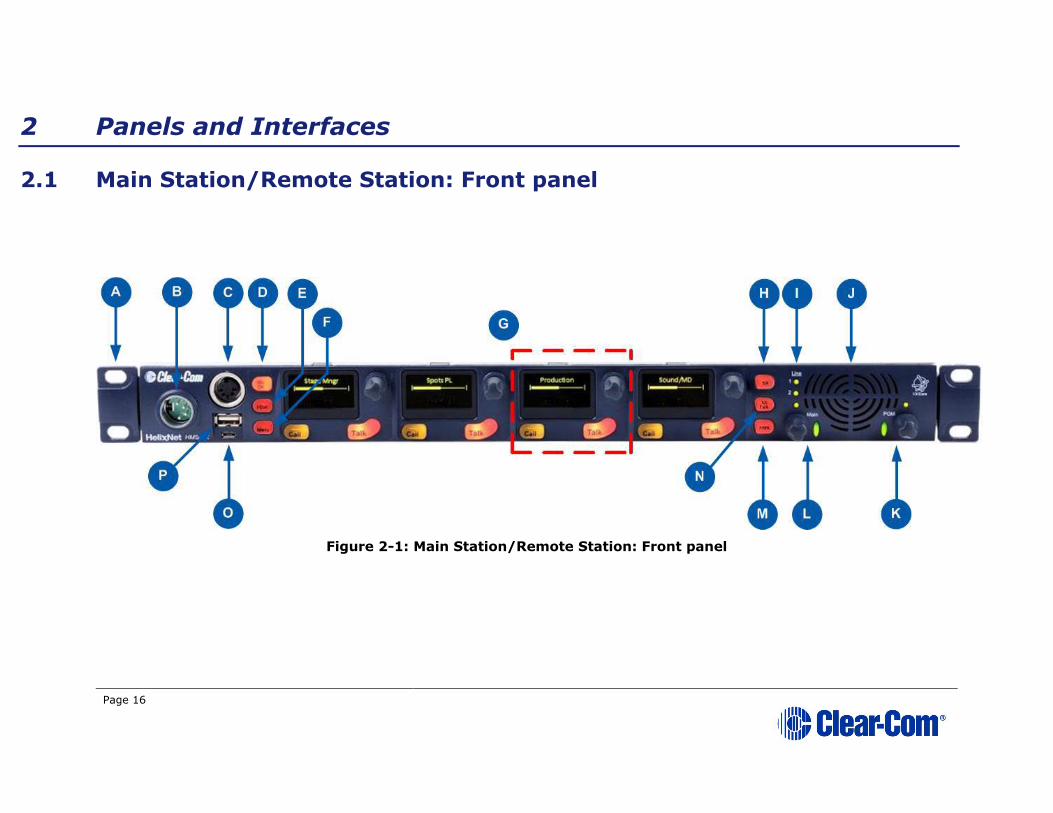
Figure 2-1: Main Station/Remote Station: Front panel

Page 17
Key to Main Station/Remote Station: Front panel
Feature Description
A
Ear for rack mounting Main Station/Remote Station.
B
Headset socket (4-pin XLR–M)
Pin Function
1 Mic ground
2 Mic +
3 Earphone ground
4 Earphone
Table 2-1: Headset socket pin out
C
Gooseneck microphone socket (3-pin female Tuchel connector)
D
Mic control [MIC ON]. Press to activate mic audio.
E
Headset key [HSET]. Press to activate the headset mic. When the headset is connected, the gooseneck microphone is disconnected.
Audio output to the loudspeaker is diverted to the headphones.
F
Menu. Press to display the Main Station menus in the display
screens [ G
]. Use the rotary control for each display screen to
scroll and select menu items. See 2.1.1 Main Station/Remote
Channel keyset.
G
Channel keyset. There is a keyset (set of controls) addressable to any of the available Channels. See 2.1.1 Main Station/Remote
Channel keyset.
H
Stage Announce [SA]. Press to talk to connected Public Address
(PA) / Stage Announce (SA) system (see 2.2 HMS-4X Main Station:
rear panel).
SA mutes any active Talk key on the station, and transmits audio
from either headset or gooseneck microphone to the SA Output port
on the rear of the unit. If the SA is assigned to a Channel, then any
talker within the Channel has their audio routed to the associated SA
Port.
When the SA is pressed, Mic select [MIC ON] is also lit bright red,
indicating that mic audio is active. See 7.8 Using the SA [Stage
Announce] key.
Page 18
Key to Main Station/Remote Station: Front panel
Feature Description
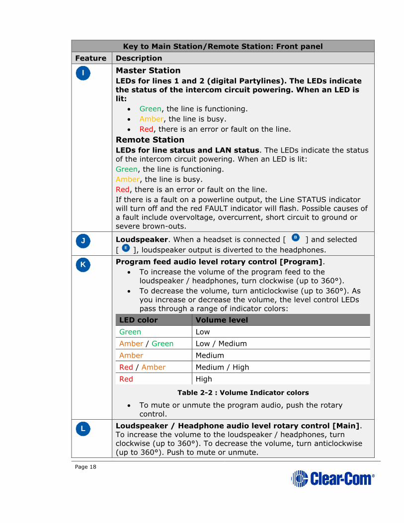
I
Master Station
LEDs for lines 1 and 2 (digital Partylines). The LEDs indicate
the status of the intercom circuit powering. When an LED is
lit:
• Green, the line is functioning.
• Amber, the line is busy.
• Red, there is an error or fault on the line.
Remote Station
LEDs for line status and LAN status. The LEDs indicate the status
of the intercom circuit powering. When an LED is lit:
Green, the line is functioning.
Amber, the line is busy.
Red, there is an error or fault on the line.
If there is a fault on a powerline output, the Line STATUS indicator
will turn off and the red FAULT indicator will flash. Possible causes of
a fault include overvoltage, overcurrent, short circuit to ground or
severe brown-outs.
J
Loudspeaker. When a headset is connected [ B ] and selected
[ E ], loudspeaker output is diverted to the headphones.
K
Program feed audio level rotary control [Program].
• To increase the volume of the program feed to the
loudspeaker / headphones, turn clockwise (up to 360°).
• To decrease the volume, turn anticlockwise (up to 360°). As
you increase or decrease the volume, the level control LEDs
pass through a range of indicator colors:
LED color Volume level
Green Low
Amber / Green Low / Medium
Amber Medium
Red / Amber Medium / High
Red High
Table 2-2 : Volume Indicator colors
• To mute or unmute the program audio, push the rotary
control.
L
Loudspeaker / Headphone audio level rotary control [Main]. To increase the volume to the loudspeaker / headphones, turn
clockwise (up to 360°). To decrease the volume, turn anticlockwise
(up to 360°). Push to mute or unmute.

Page 19
Key to Main Station/Remote Station: Front panel
Feature Description
As you increase or decrease the volume, the level control LEDs pass
through a range of indicator colors. For more information, see Table
2-2 : Volume Indicator colors
M
Main Station:
Remote Mic Kill [RMK]. Press to:
• Unlatch all latched talk keys for either all displayed Channels
or all Channels within the system (configurable within the
Role)
Remote Station:
Option [OPT] – Can be configured as an RMK button (see section
7.9 Using the RMK [Remote Mic Kill] key).
N
All Talk. Press to talk to all Channels (intercom devices and systems)
connected to the Main Station.
O
USB 2.0 (Micro-AB) connector. For software upgrades (see 5.8.2 Updating the software and 5.8.6 Saving and restoring the
software settings.).
Note: This connector is not present on the Remote Station.
P
USB 2.0 (Standard-A) connector. For software upgrades (see 5.8.2 Updating the software and 5.8.6 Saving and restoring the
software settings.).
Table 2-3 Key to Main Station/Remote Station front panel diagram
Note: The Main Station/Remote Station does not have a power switch, button
or key. The system powers up when you connect the power supply.
Power up time depends on the amount of equipment connected.

Page 20
2.1.1 Main Station/Remote Channel keyset and display
Figure 2-2: Main Station/Remote Station (Front panel): Keyset
Key to Main Station/Remote Station front panel: Channel keyset
Feature Description
A
Display screen.
There are multiple screensaver options. If the Rotary controls are
touched, this screen also displays the sound level on the Channel
(controlled by the rotary) and the system information icons. For an
explanation of system information icons see Table 2-5 Main
Station/Remote Station display icons and indicators.
In Menu mode, the display screens display the four levels of menu.
The menu hierarchy proceeds left to right:
• The top level menu is presented in the first screen (furthest
left on the front panel).
• The lowest level menu is presented in the fourth screen
(furthest right on the front panel).
If the display is in Menu mode, the display screen times out of Menu mode and displays the Channel label if no key is pressed for 20
seconds.
For more information about Menu mode, see 5.1 Using the Menus.
B
Rotary control. Turn to increase or decrease the listen volume level for the Channel. Also, push the control to mute or unmute audio
level. In Menu mode, use the control to scroll menu items. To select
menu items, press the control.
C
Talk key. Press to talk on the Channel and to all nodes (intercom
devices and systems) listening into the Channel.
D
Call key. Press to send a call signal to all nodes (intercom devices
and systems) listening into the Channel.
Table 2-4: Key to Main Station/Remote Station front panel: Key Set

Page 21
Note: If the Main Station/Remote Station remains inactive for 10 minutes, the display
screens enter screensaver mode (see 5.3.9 Setting the screensaver).
Main Station/Remote Station display icons and indicators
Name Icon Description
Channel
label A descriptive name for the Channel. The
maximum length is 10 characters.
Channel listen
volume level
The volume of the Channel audio.
Link with another
HMS
Appears on the Main Station when linking is
enabled.
Not linked Appears on the Main Station when a connection
to another Main Station is lost.
Paired
Appears on the Remote Station and Speaker
Station when it is connected properly over LAN.
Not paired
Flashes on the Remote Station and Speaker
Station when the connection is not configured
properly.
Signal
strength Appears on the Remote Station, Speaker Station
and beltpack. One to five bars indicate the
strength of the signal from the Main Station.
Locked Locked Appears on the beltpack when you try to access the menu while the menu has been locked at the
Main Station.
Mute
Appears on the Main Station, Remote Station and Speaker Station when the rotary control for
any Channel on the Main/Remote Station is
pressed.
Opto (GPI) Appears on the Main Station and Remote Station close to the Call or Talk button if it is associated
with an Opto.
Relay (GPO) Appears on the Main Station and Remote Station
close to the Call or Talk button if it is associated
with a Relay.
Program PGM Appears on the Main Station, Remote Station, Speaker Station and beltpack when a program
input is assigned to a Channel.
IFB IFB Appears on the Main Station, Remote Station, Speaker Station and beltpack when a program
input is assigned to a Channel and IFB is
enabled.

Page 22
Main Station/Remote Station display icons and indicators
Name Icon Description
2W/4W 2W/4W Appears on the Main Station, Remote Station and Speaker Station when a 2W/4W input is
assigned to a Channel.
Limiter LIM Appears on the Main Station, Remote Station, Speaker Station and beltpack when the headset
limiter is enabled.
Expansion
Appears on the Main Station and Remote Station
when the device is part of an Expansion Group.
Warning
Appears on the Main Station, Remote Station, Speaker Station and beltpack when something is
wrong. Warning messages can be accessed in
the Diagnostic menu.
Table 2-5 Main Station/Remote Station display icons and indicators

Page 23
2.2 HMS-4X Main Station: rear panel
Figure 2-3: HMS-4X Main Station: rear panel (including optional modules HLI-2W2 and HLI-4W2)

Page 24
Key to Main Station: rear panel
Feature Description
A
Power supply with metal cable clip. The power supply operates
at 100 - 240 VAC / 50-60Hz / 250 watts / T 3.15A H 250 V.
B
Control I/O (25 way female D-type). Use to connect up to 4 relay
control outputs and 4 optically isolated control inputs (see 5.5
Configuring the Control I/O).
Pin Function Pin Function
Pin 1 Relay 1 NC Pin 14 Relay1 Pole
Pin 2 Relay 1-NO Pin 15 Relay 2 NC
Pin 3 Relay2-Pole Pin 16 Relay 2-NO
Pin 4 Relay 3 NC Pin 17 Relay3 Pole
Pin 5 Relay 3-NO Pin 18 Relay 4 NC
Pin 6 Relay4-Pole Pin 19 Relay 4-NO
Pin 7 Pin 20 +5V
Pin 8 GND Pin 21 +5V
Pin 9 GND Pin 22 Opto 1-
Pin 10 Opto 1+ Pin 23 Opto 2-
Pin 11 Opto 2+ Pin 24 Opto 3-
Pin 12 Opto 3+ Pin 25 Opto 4-
Pin 13 Opto 4+
Table 2-6: Control I/O pin out
C
Hot Mic output. This connection is a 1/4-in (0.64 cm) phone jack. It provides an output signal from the selected headset or panel
microphone. The Hot Mic output is always live. Audio from the mic is
routed through the Hot Mic output even if the mic is inactive (off).
Pin Function
Tip Mic
Ring IFB mute signal
Sleeve Ground
Table 2-7: Hot Mic pin out

Page 25
D
SA [Stage Announce] line out (3-pin male XLR).
Pin Function
Pin 1 Ground
Pin 2 Positive
Pin 3 Negative
Table 2-8: SA pin out
E
Program Input (3-pin female XLR).
Pin Function
Pin 1 Ground
Pin 2 Positive
Pin 3 Negative
Table 2-9: Program input pin out
F
Line 1 (digital Partyline). (3-pin male and female XLR
connectors).
Pin Function
Pin 1 Ground
Pin 2 +30V DC and Audio
Pin 3 -30V DC and Audio
Table 2-10: Line 1 pin out
G
Line 2 (digital Partyline). (3-pin male and female XLR
connectors).
Pin Function
Pin 1 Ground
Pin 2 +30V DC and Audio
Pin 3 -30V DC and Audio
Table 2-11: Line 2 pin out
H
Slots for optional interface modules.
H – Slot 1
I – Slot 2
J – Slot 3
For more information, see HMS-4X Main Station rear panel:
Interface modules.
I
J

Page 26
Table 2-12: Key to HMS-4X Main Station rear panel diagram
Warning: Only connect power supply to earthed supply sockets. Ensure that the
power supply is routed to avoid sharp bends, hot surfaces, pinches and abrasion.
For more safety guidance, see the Safety Instructions at the front of this guide.
Note: The HMS-4X Main Station does not have a power switch, button or key.
The system powers up when you connect the power supply.
2.2.1 HMS-4X Main Station rear panel: Interface modules
Up to three Interface modules (of the same or different types) can be fitted to the
extension bay of the Main Station. When looking at the rear of the Main Station,
expansion slot 1 is the left-hand slot, expansion slot 2 is the middle slot, and expansion slot 3 is the right-hand slot.
Warning: The interface modules are NOT hot pluggable. Ensure that the
Main Station is powered down before inserting or removing modules.
Interface module Description
Two-wire interface
module (HLI-2W2)
This is a two Channel, 2-wire device that enables interoperability with, CellCom® / FreeSpeak®, and HME
DX systems, as well as both Clear-Com and RTS analog
Partyline systems.
Note: This module requires a powered analog Partyline.
The module provides two analog Partyline connectors (3
pin female XLR connectors) with the following pin out:
Pin Function
1 Ground
2 Power [Option for RTS mode: power and
audio]
3 Audio
Table 2-13: two-wire Interface Module pin out
Use HelixNet Main Station menus to set the module for either RTS or Clear-Com systems. If RTS mode is
selected, you can set either:
• Pin 2 for power to mixed audio Channel (1 – 24)
• Pin 3 for power to mixed audio Channel (1 – 24)
• Select either pin and assign required Channel to it.

Page 27
Interface module Description
Four-wire interface
module (HLI-4W2)
This is a two Channel, 4-wire device that enables interoperability with the Eclipse® digital matrix system
and other four-wire audio sources such as telephone
hybrids, AB-120/-100, PA (Public Address) / SA (Stage
Announce) systems. The module also enables HelixNet-to-HelixNet connections using four-wire audio ports. Two
four-wire connectors (etherCON type RJ45 socket) are
provided with the following pin out:
Pin Function
1 RS-422 data TX+
2 RS-422 data TX-
3 Audio send +
4 Audio receive +
5 Audio receive -
6 Audio send -
7 RS-422 data RX+
8 RS-422 data RX-
Table 2-14: four-wire interface module pin out

Page 28
Interface module Description
Ethernet interface
module (HLI-ET2)
Enables linking of Main Stations, and connection of Remote Stations, Speaker Stations and the HXII-BP
beltpack via LAN. Contains Two 10/100 Mbps RJ45
etherCON ports.
An LED on the right-hand side above the connector
flashes green when there is network activity.
Pin Name Function
1 TX+ Transmit Data+
2 TX- Transmit Data-
3 RX+ Receive Data+
4 n/c Not connected
5 n/c Not connected
6 RX- Receive Data-
7 n/c Not connected
8 n/c Not connected
Table 2-15: Ethernet interface module pin out
Warning: Both ports are configured to bridge traffic from one port to the other in order to
work in a daisy-chained configuration.
Spanning Tree Protocol is not enabled on
these ports, therefore do not connect them
both to the same network.
Fiber interface
module (HLI-FBS)
Enables linking of Main Stations. Contains two SFP cage
slots. The module is supplied with one transceiver fitted.
Any 100BASE-X SFP can be connected.
An LED at the side of each connector flashes green when
there is network activity.
Warning: Both ports are configured to bridge traffic from one port to the other in order to
work in a daisy-chained configuration.
Spanning Tree Protocol is not enabled on these ports, therefore do not connect them
both to the same network.
Table 2-16: HMS-4X Main Station rear panel: Interface Modules
Page 29
2.3 Remote Station rear panel
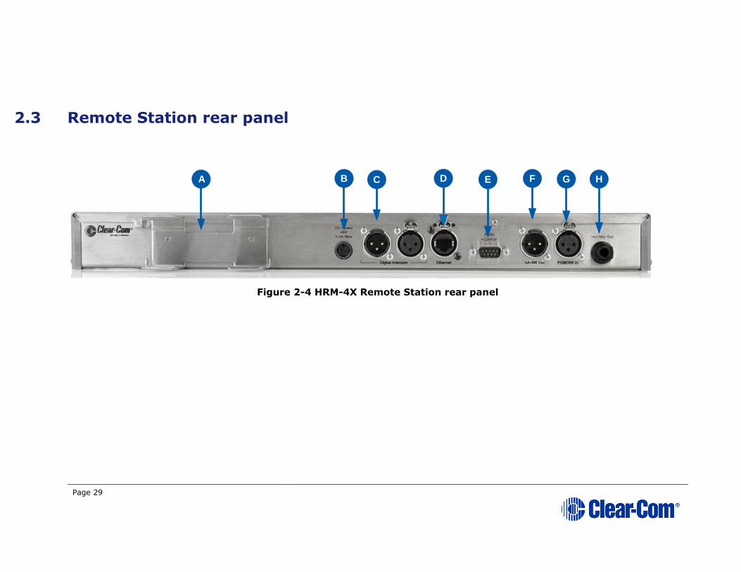
Figure 2-4 HRM-4X Remote Station rear panel
A
B C E F GD
H

Page 30
Key to Remote Station: rear panel
Feature Description
A
PSU holder for a separate external AC-DC power supply. The external PSU provides the 48V required and at its input takes 100-
240V, 50-60Hz.
B
Power supply. The power input connector is a low voltage DC
connection. It is 48VDC at a max power of 12.95W.
C
Line 1 (digital Partyline). (3-pin male and female XLR
connectors).
Pin Function
Pin 1 Ground
Pin 2 +30V DC and Audio
Pin 3 -30V DC and Audio
Table 2-17: Line 1 pin out
D
Ethernet/Power Over Ethernet (RJ45 connector)
An LED on the left-hand side of the connector illuminates when the
link is working.
An LED on the right-hand side of the connector flashes green when there is network activity.
Pin Name Function
1 TX+ Transmit Data+
2 TX- Transmit Data-
3 RX+ Receive Data+
4 n/c Not connected
5 n/c Not connected
6 RX- Receive Data-
7 n/c Not connected
8 n/c Not connected
When connected over PoE, the Remote Station draws 13 Watts from
the PoE switch.
Page 31
Key to Remote Station: rear panel
Feature Description
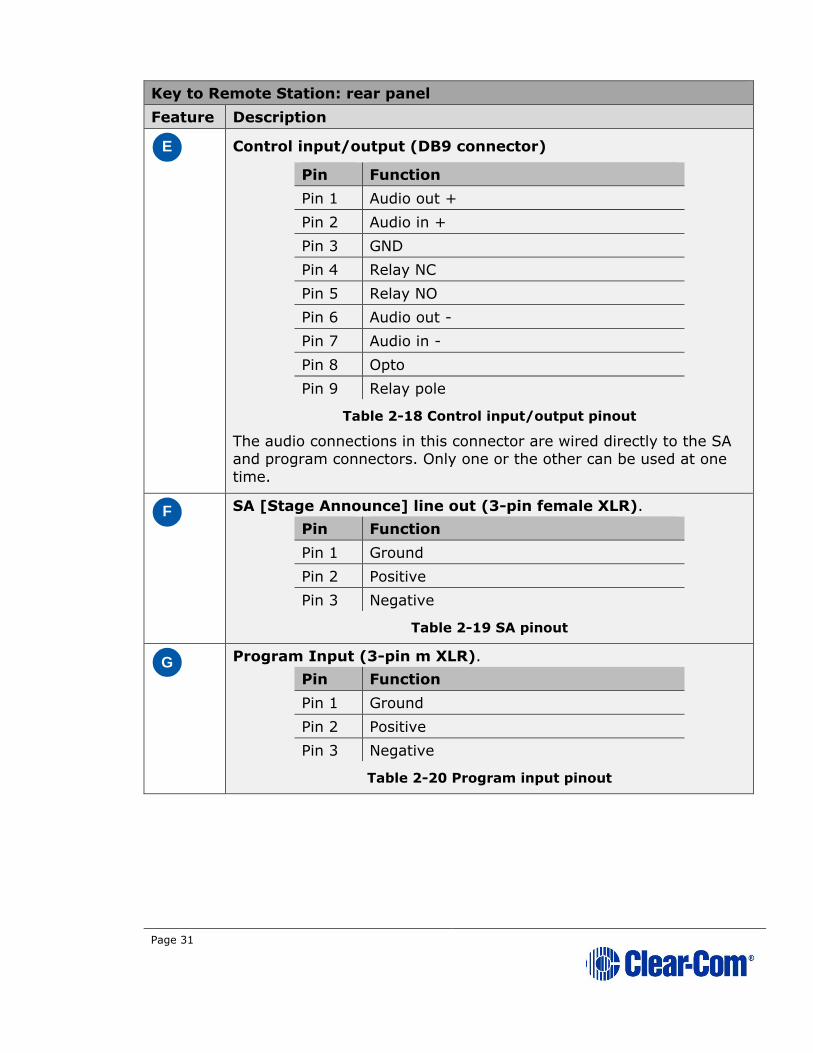
E
Control input/output (DB9 connector)
Pin Function
Pin 1 Audio out +
Pin 2 Audio in +
Pin 3 GND
Pin 4 Relay NC
Pin 5 Relay NO
Pin 6 Audio out -
Pin 7 Audio in -
Pin 8 Opto
Pin 9 Relay pole
Table 2-18 Control input/output pinout
The audio connections in this connector are wired directly to the SA
and program connectors. Only one or the other can be used at one
time.
F
SA [Stage Announce] line out (3-pin female XLR).
Pin Function
Pin 1 Ground
Pin 2 Positive
Pin 3 Negative
Table 2-19 SA pinout
G
Program Input (3-pin m XLR).
Pin Function
Pin 1 Ground
Pin 2 Positive
Pin 3 Negative
Table 2-20 Program input pinout

Page 32
Key to Remote Station: rear panel
Feature Description
H
Hot Mic output. This connection is a 1/4-in (0.64 cm) phone jack. It provides an output signal from the selected headset or panel
microphone. The Hot Mic output is always live. Audio from the mic is
routed through the Hot Mic output even if the mic is inactive (off).
Pin Function
Tip Mic
Ring IFB mute signal
Sleeve Ground
Table 2-21: Hot Mic pin out
Table 2-22: Key to Remote Station rear panel diagram

Page 33
2.4 Speaker Station
Figure 2-5 Speaker Station front panel

Page 34
Key to Speaker Station front panel
Feature Description
A
Tilt adjustable display screen. The following default information is
displayed:
• The Channel label.
• The Channel listen (volume) level.
For a full description of the display screen information, see Table
2-5 Main Station/Remote Station display icons and indicators.
In Menu mode, the display screens display the two levels of menu.
The menu hierarchy proceeds left to right:
• The top level menu is presented in the first screen (furthest
left on the front panel).
• The lower level menu is presented in the second screen.
If the display is in Menu mode, the display screen times out of Menu
mode and displays the Channel label if no key is pressed for 20
seconds.
For more information about Menu mode, see 5.1 Using the Menus.
B
Rotary control. Turn to increase or decrease the listen volume level
for the Channel. Also, push the control to mute or unmute audio
level. In Menu mode, use the control to scroll menu items. To select
menu items, press the control.
C
Talk key. Press to talk on the Channel and to all nodes (intercom
devices and systems) listening into the Channel.
D
Loudspeaker / Headphone audio level rotary control [Main].
To increase the volume to the loudspeaker / headphones, turn
clockwise (up to 360°). To decrease the volume, turn counter
clockwise (up to 360°). As you increase or decrease the volume, the
level control LEDs pass through a range of indicator colors. For more
information, see Table 2-2: Volume Indicator colors
E
Program feed audio level Trim Pot control [PGM]. To increase
the volume of the program feed to the loudspeaker / headphones,
turn clockwise (up to 360°). To decrease the volume, turn counter clockwise (up to 360°).
To mute or unmue the Channel audio, push the control.
F
Call key. Press to send a call signal to all Keysets assigned to the
same Channel. There are two Call keys on the beltpack, one for each
of the displayed Channels.
G
Headset socket (4-pin XLR–M)
Pin Function
1 Mic ground
2 Mic positive
3 Earphone ground
4 Earphone positive
Page 35
Key to Speaker Station front panel
Feature Description
Table 2-23 : Headset socket pin out
H
Headset/microphone key set. There is a keyset (set of controls)
to control the headset/microphone inputs and menu options. See
Figure 2-6 Speaker Station keyset.
I
Gooseneck microphone connector (3-pin female Tuchel
connector)
Table 2-24 Key to Speaker Station front panel
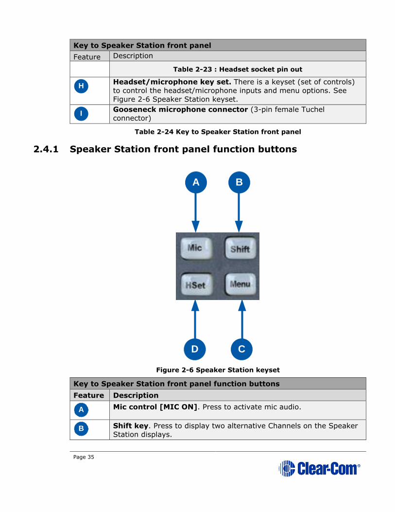
2.4.1 Speaker Station front panel function buttons
Figure 2-6 Speaker Station keyset
Key to Speaker Station front panel function buttons
Feature Description
A
Mic control [MIC ON]. Press to activate mic audio.
B
Shift key. Press to display two alternative Channels on the Speaker
Station displays.
A B
D C

Page 36
Key to Speaker Station front panel function buttons
Feature Description
C
Menu. Press to display the Speaker Station menus in the display screens. Use the rotary control for each display screen to scroll and
select menu items.
D
Headset key [HSET]. Press to activate the headset mic. When the headset is connected, the gooseneck microphone is disconnected.
Audio output to the loudspeaker is diverted to the headphones.
Table 2-25 Key to Speaker Station front panel keyset
Page 37
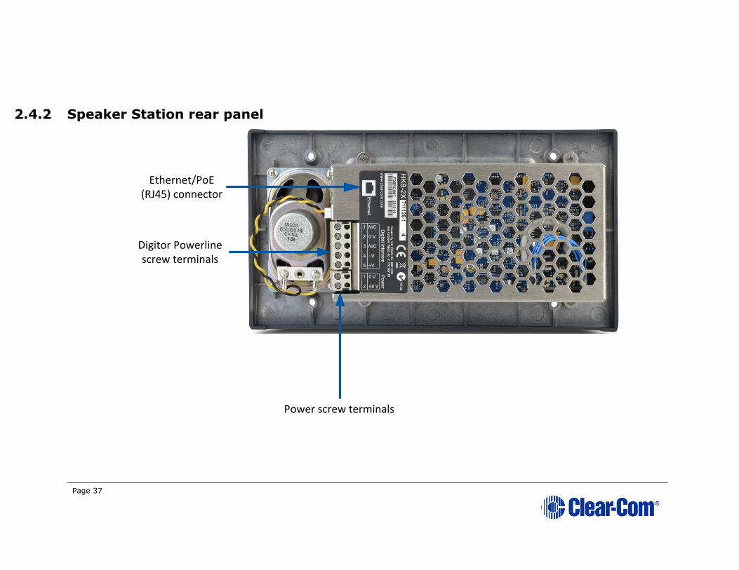
2.4.2 Speaker Station rear panel
Power screw terminals
Ethernet/PoE (RJ45) connector
Digitor Powerline screw terminals
Page 38
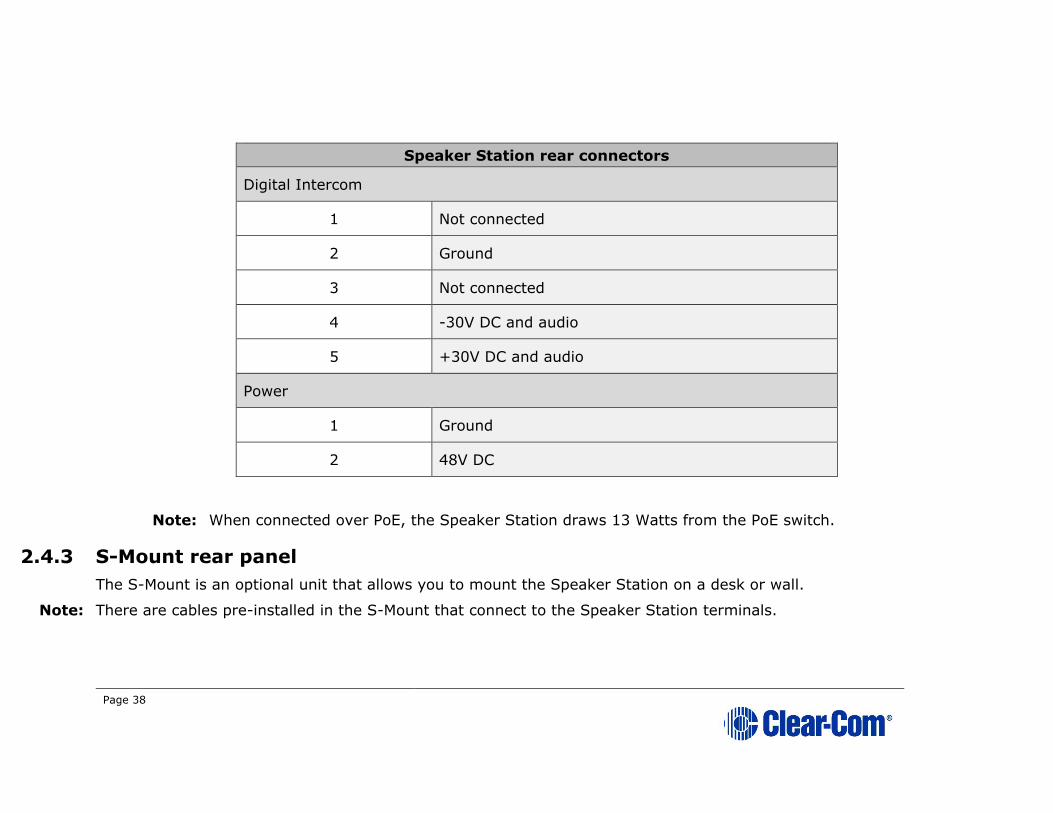
Speaker Station rear connectors
Digital Intercom
1 Not connected
2 Ground
3 Not connected
4 -30V DC and audio
5 +30V DC and audio
Power
1 Ground
2 48V DC
Note: When connected over PoE, the Speaker Station draws 13 Watts from the PoE switch.
2.4.3 S-Mount rear panel
The S-Mount is an optional unit that allows you to mount the Speaker Station on a desk or wall.
Note: There are cables pre-installed in the S-Mount that connect to the Speaker Station terminals.

Page 39
Page 40
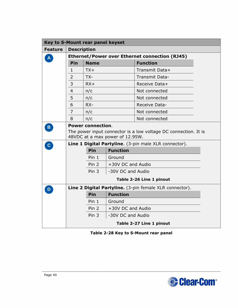
Key to S-Mount rear panel keyset
Feature Description
A
Ethernet/Power over Ethernet connection (RJ45)
Pin Name Function
1 TX+ Transmit Data+
2 TX- Transmit Data-
3 RX+ Receive Data+
4 n/c Not connected
5 n/c Not connected
6 RX- Receive Data-
7 n/c Not connected
8 n/c Not connected
B
Power connection.
The power input connector is a low voltage DC connection. It is
48VDC at a max power of 12.95W.
C
Line 1 Digital Partyline. (3-pin male XLR connector).
Pin Function
Pin 1 Ground
Pin 2 +30V DC and Audio
Pin 3 -30V DC and Audio
Table 2-26 Line 1 pinout
D
Line 2 Digital Partyline. (3-pin female XLR connector).
Pin Function
Pin 1 Ground
Pin 2 +30V DC and Audio
Pin 3 -30V DC and Audio
Table 2-27 Line 1 pinout
Table 2-28 Key to S-Mount rear panel

Page 41
2.5 HBP-2X Beltpack
For information about the HXII-BP-X4 Beltpack, see 2.6 HXII-BP-X4 Beltpack.
2.5.1 HBP-2X user controls (front and side view)
Figure 2-7: HBP-2X Beltpack (front and side view)
Note: The beltpack has two Keysets, each containing one Call button (E) and one Talk
button (F).

Page 42
Key to HBP-2X user controls (front and side view)
Feature Description
A
Menu key. Press firmly to enter Menu mode (see also D
E
). To
exit Menu mode, press the Menu key again.
The display screen times out of Menu mode and displays the Channel
label(s) if no key is pressed for 20 seconds.
B
USB 2.0 (Micro-AB) connector. Used for the USB light flasher
feature. See 15.8 Call a beltpack using the USB flasher feature.
C
Casing. Metal casing for robust use. For information about the beltclip, beltloops, and feet, see 2.5.3 HBP-2X beltclip, beltloops and
feet (base view).
Keyset
D
Rotary control. Turn to increase and decrease the listen volume
level for the Channel.
In Menu mode, you can turn either of the side-mounted rotary
controls to scroll menu items. To select (enter) items, press the
right-hand Call key (see E
).
E
Call key. Press to send a call signal to all Keysets assigned to the same Channel. There are two Call keys on the beltpack, one for each
of the supported Channels.
In Menu mode, press the right-hand Call key to select (enter) menu
items (see also A
D
). Use the left-hand Call key to go back one
menu level.
F
Talk key. Press to talk to all nodes (intercom devices and systems)
listening into the Channel. There are two Talk keys on the beltpack,
one for each of the supported Channels.
G
Display screen. When the beltpack is not in Menu mode, the labels and volume level for each of the two Channels supported by the
beltpack are displayed on screen. For a full description of the display
screen information, see Table 2-5 Main Station/Remote Station
display icons and indicators.
Note: The beltpack has two Keysets, each containing one Call button
(E) and one Talk button (F).
Table 2-29: Key to HBP-2X Beltpack (front and side view)
Page 43
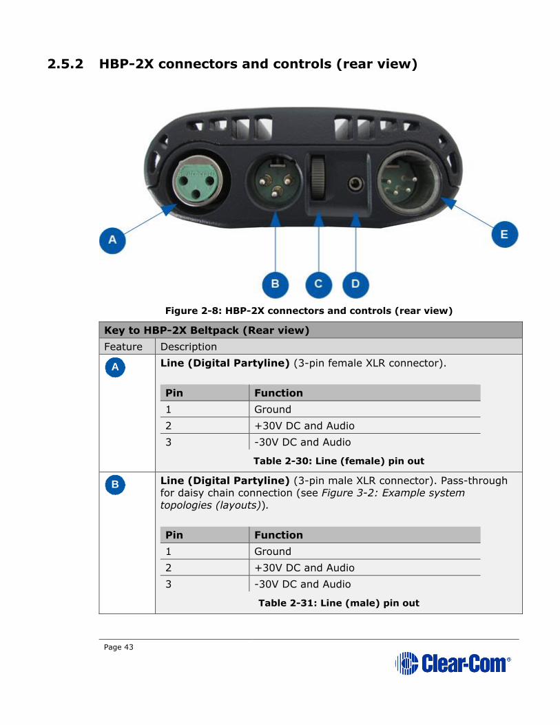
2.5.2 HBP-2X connectors and controls (rear view)
Figure 2-8: HBP-2X connectors and controls (rear view)
Key to HBP-2X Beltpack (Rear view)
Feature Description
A
Line (Digital Partyline) (3-pin female XLR connector).
Pin Function
1 Ground
2 +30V DC and Audio
3 -30V DC and Audio
Table 2-30: Line (female) pin out
B
Line (Digital Partyline) (3-pin male XLR connector). Pass-through for daisy chain connection (see Figure 3-2: Example system
topologies (layouts)).
Pin Function
1 Ground
2 +30V DC and Audio
3 -30V DC and Audio
Table 2-31: Line (male) pin out
Page 44
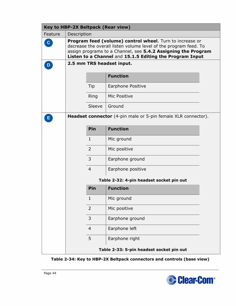
Key to HBP-2X Beltpack (Rear view)
Feature Description
C
Program feed (volume) control wheel. Turn to increase or decrease the overall listen volume level of the program feed. To
assign programs to a Channel, see 5.4.2 Assigning the Program
Listen to a Channel and 15.1.5 Editing the Program Input
D
2.5 mm TRS headset input.
Function
Tip Earphone Positive
Ring Mic Positive
Sleeve Ground
E
Headset connector (4-pin male or 5-pin female XLR connector).
Pin Function
1 Mic ground
2 Mic positive
3 Earphone ground
4 Earphone positive
Table 2-32: 4-pin headset socket pin out
Pin Function
1 Mic ground
2 Mic positive
3 Earphone ground
4 Earphone left
5 Earphone right
Table 2-33: 5-pin headset socket pin out
Table 2-34: Key to HBP-2X Beltpack connectors and controls (base view)

Page 45
2.5.3 HBP-2X beltclip, beltloops and feet (base view)
Figure 2-9: HBP-2X Beltpack: base view
Key to HBP-2X Beltpack (Base view)
Feature Description
A
Beltclip. The beltclip is secured to the unit with three screws, and
may be removed, according to your requirements.
B
Feet (positions only). The beltpack can also be placed on a level
surface (once the beltclip has been removed). To give the beltpack more grip on the surface, attach the four rubber feet supplied with
the beltpack.
C
Beltloops (one either side). Use to thread through a belt or strap
for securing the beltpack to a belt or a fixed position.
Table 2-35: Key to HBP-2X Beltclip, beltloops and feet (base view)
Page 46
2.6 HXII-BP-X4 Beltpack
For information about the HBP-2X Beltpack, see 2.5 HBP-2X Beltpack.
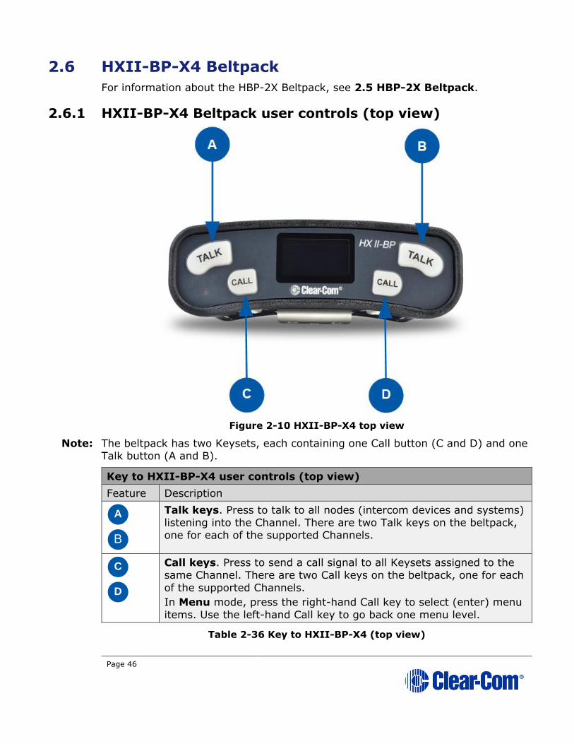
2.6.1 HXII-BP-X4 Beltpack user controls (top view)
Figure 2-10 HXII-BP-X4 top view
Note: The beltpack has two Keysets, each containing one Call button (C and D) and one
Talk button (A and B).
Key to HXII-BP-X4 user controls (top view)
Feature Description
A
B
Talk keys. Press to talk to all nodes (intercom devices and systems)
listening into the Channel. There are two Talk keys on the beltpack,
one for each of the supported Channels.
C
D
Call keys. Press to send a call signal to all Keysets assigned to the same Channel. There are two Call keys on the beltpack, one for each
of the supported Channels.
In Menu mode, press the right-hand Call key to select (enter) menu
items. Use the left-hand Call key to go back one menu level.
Table 2-36 Key to HXII-BP-X4 (top view)

Page 47
2.6.2 HXII-BP-X4 Beltpack connectors and controls (front view)
Figure 2-11 HXII-BP-X4 front view
Page 48
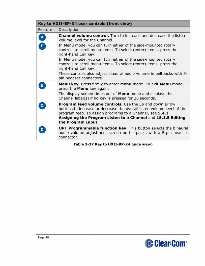
Key to HXII-BP-X4 user controls (front view)
Feature Description
A
E
Channel volume control. Turn to increase and decrease the listen
volume level for the Channel.
In Menu mode, you can turn either of the side-mounted rotary
controls to scroll menu items. To select (enter) items, press the
right-hand Call key.
In Menu mode, you can turn either of the side-mounted rotary
controls to scroll menu items. To select (enter) items, press the
right-hand Call key.
These controls also adjust binaural audio volume in beltpacks with 5-
pin headset connectors.
B
Menu key. Press firmly to enter Menu mode. To exit Menu mode,
press the Menu key again.
The display screen times out of Menu mode and displays the
Channel label(s) if no key is pressed for 20 seconds.
C
Program feed volume controls. Use the up and down arrow
buttons to increase or decrease the overall listen volume level of the program feed. To assign programs to a Channel, see 5.4.2
Assigning the Program Listen to a Channel and 15.1.5 Editing
the Program Input.
D
OPT Programmable function key. This button selects the binaural audio volume adjustment screen on beltpacks with a 5-pin headset
connector.
Table 2-37 Key to HXII-BP-X4 (side view)
Page 49
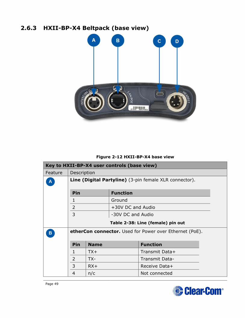
2.6.3 HXII-BP-X4 Beltpack (base view)
Figure 2-12 HXII-BP-X4 base view
Key to HXII-BP-X4 user controls (base view)
Feature Description
A
Line (Digital Partyline) (3-pin female XLR connector).
Pin Function
1 Ground
2 +30V DC and Audio
3 -30V DC and Audio
Table 2-38: Line (female) pin out
B
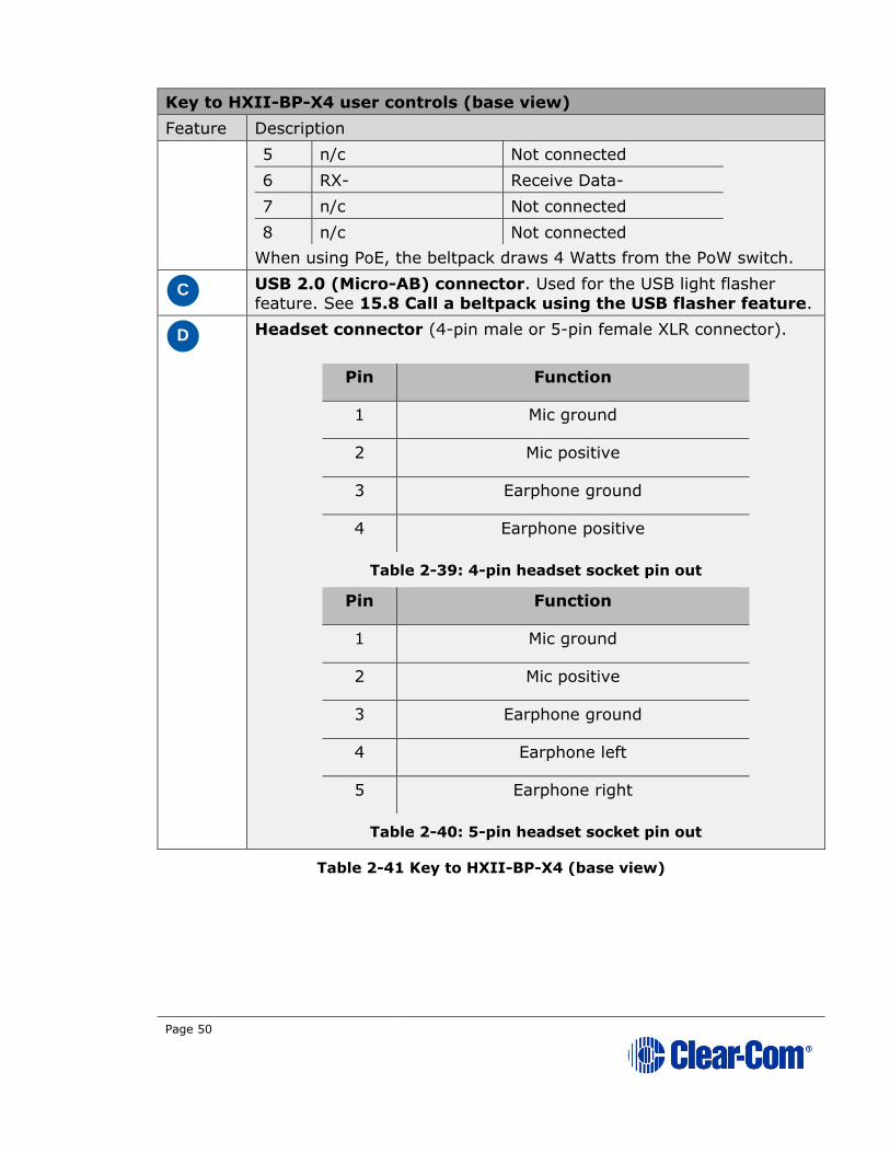
etherCon connector. Used for Power over Ethernet (PoE).
Pin Name Function
1 TX+ Transmit Data+
2 TX- Transmit Data-
3 RX+ Receive Data+
4 n/c Not connected
Page 50
Key to HXII-BP-X4 user controls (base view)
Feature Description
5 n/c Not connected
6 RX- Receive Data-
7 n/c Not connected
8 n/c Not connected
When using PoE, the beltpack draws 4 Watts from the PoW switch.
C
USB 2.0 (Micro-AB) connector. Used for the USB light flasher
feature. See 15.8 Call a beltpack using the USB flasher feature.
D
Headset connector (4-pin male or 5-pin female XLR connector).
Pin Function
1 Mic ground
2 Mic positive
3 Earphone ground
4 Earphone positive
Table 2-39: 4-pin headset socket pin out
Pin Function
1 Mic ground
2 Mic positive
3 Earphone ground
4 Earphone left
5 Earphone right
Table 2-40: 5-pin headset socket pin out
Table 2-41 Key to HXII-BP-X4 (base view)

Page 51
2.6.4 HXII-BP-X4 Beltpack (beltloops and clip)
Figure 2-13 HXII-BP-X4 beltloops and clip

Page 52
Key to HXII-BP-X4 beltloops and clip
Feature Description
A
Beltloops. Use to thread through a belt or strap for securing the beltpack to a belt or a fixed position. You can also extend the
beltloops to allow you to mount the beltpack on a flat surface.
B
Beltclip. Use to fasten to a belt or similar structurer. The beltclip
also has three holes for wall mounting.
Table 2-42 Key to HXII-BP-X4 beltloops and clip
Figure 2-14 HXII-BP-X4 with extended belt loops for desk-top mounting

Page 53
3 Installing HelixNet Partyline
This chapter describes how to install your HelixNet Partyline system. It also
provides basic guidance on planning your installation.
For related information, see 24 Cabling reference and the Online Powerline
cable distance calculator at:
http://www.clearcom.com/userfiles/file/Software/HelixNetCablingCalculator/index
.html#/
Tip: For guidance on connecting HelixNet Partyline to other systems, using the optional interface modules, see 19 Connecting to Other Intercom Systems.
Do not plug any non-approved equipment into HelixNet Partyline.
HelixNet Partyline operates at different voltage levels than analog two-wire Partyline systems. Do not plug any analog two-wire
Partyline equipment into the HelixNet Partyline ports, as this may
cause damage.
For more safety instructions, see 1.1 Important Safety
instructions.
Page 54
3.1 Planning your HelixNet Partyline installation
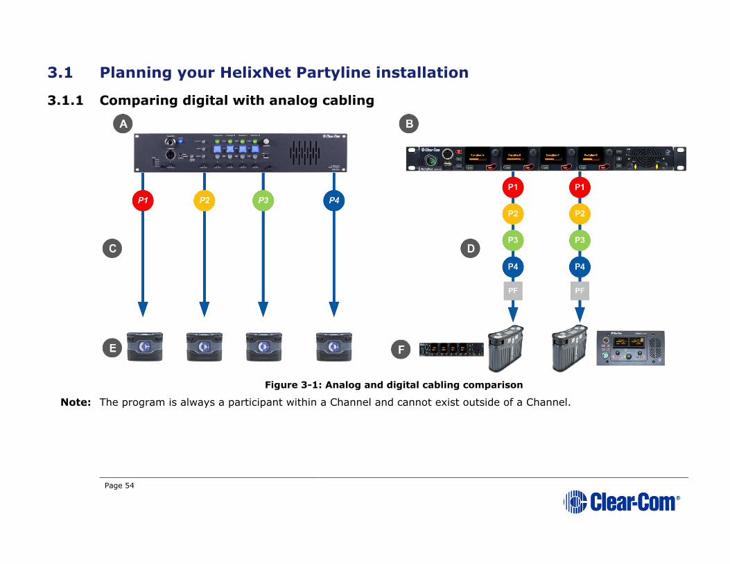
3.1.1 Comparing digital with analog cabling
Figure 3-1: Analog and digital cabling comparison
Note: The program is always a participant within a Channel and cannot exist outside of a Channel.

Page 55
Key to analog and digital cabling comparison diagram
Feature Description
A
Example 4-Channel analog Main Station (MS-704 shown).
B
HMS-4X Main Station (digital Main Station).
P1
P2
P3
P4
PF
Partyline Channel 1
Partyline Channel 2
Partyline Channel 3
Partyline Channel 4
Program Feed
Note: The program is always a participant within a Channel and
cannot exist outside of a Channel.
C
In a traditional analog Partyline system, one cable is dedicated to each Partyline Channel. This can make it more difficult to build
redundancy or spare capacity into the installation (owing to the
number of connectors / cables dedicated to the delivery of
Channels).
D
In the HelixNet system, one cable can carry multiple Channels. Because one cable can carry all Channels, the second connector for
each line can either be used for redundancy (flybacks) or for future
extensions / changes to the cabling topology (layout).
E
Example analog Partyline devices including RS-701 beltpacks. Analog beltpacks must be re-cabled to use alternative Channels, requiring
the physical re-location of cabling for new configurations.
To aid switching, Clear-Com sells additional switching equipment
(the SB-704 and RCS-2700 devices). The RS-702 (6-pin XLR)
beltpack requires the YC-36 splitter / combiner to combine 2
Channels into a 6-pin configuration, and multi-conductor cables.
The RS-703 (3-pin XLR) beltpack requires a TWC-701 device to
combine 2 Clear-Com Channels in a single twisted pair.
F
Example digital Partyline devices including beltpacks. Digital beltpacks can support any of the Partyline Channels (plus Program
Feed) whenever they are physically located on the system.
New configurations of beltpacks and Channels can be deployed
without the physical relocation of assets.
Table 3-1: Key to analog and digital cabling comparison diagram
Page 56
Note: The capabilities of different cable types may impact how far away beltpacks can
be placed from the Main Station, and the topologies you use. For more information about cabling, see 24 Cabling reference.
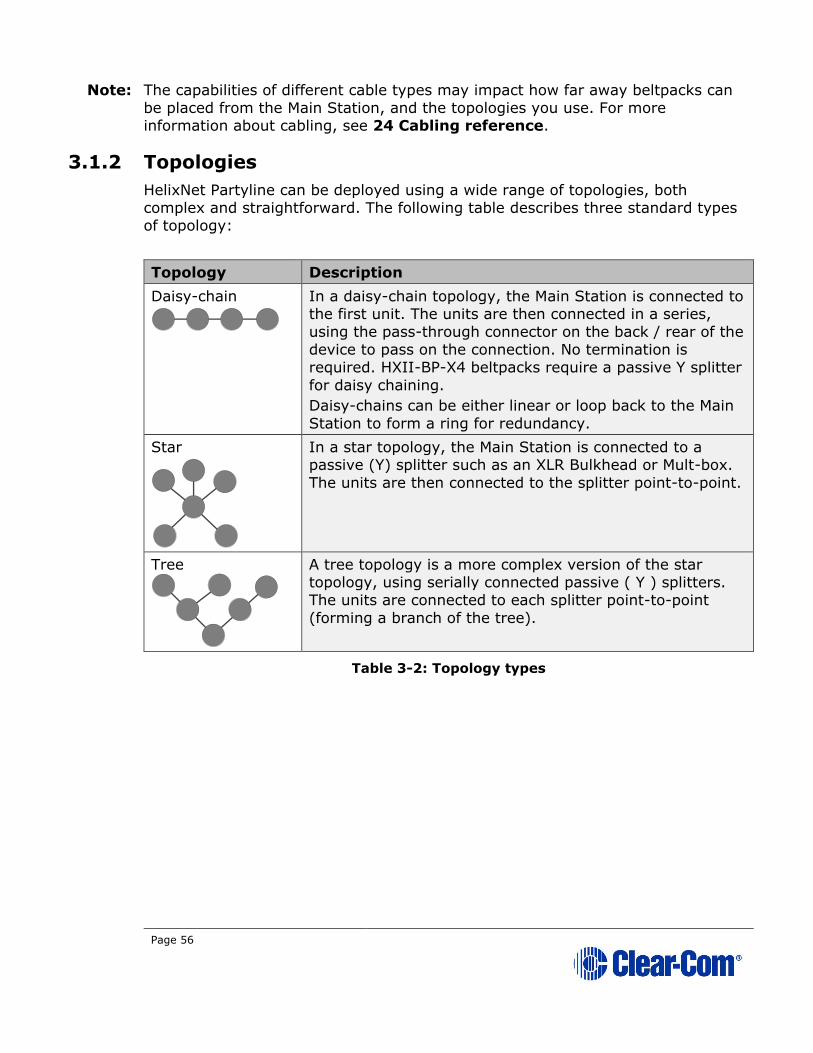
3.1.2 Topologies
HelixNet Partyline can be deployed using a wide range of topologies, both
complex and straightforward. The following table describes three standard types of topology:
Topology Description
Daisy-chain
In a daisy-chain topology, the Main Station is connected to the first unit. The units are then connected in a series,
using the pass-through connector on the back / rear of the
device to pass on the connection. No termination is
required. HXII-BP-X4 beltpacks require a passive Y splitter
for daisy chaining.
Daisy-chains can be either linear or loop back to the Main
Station to form a ring for redundancy.
Star
In a star topology, the Main Station is connected to a passive (Y) splitter such as an XLR Bulkhead or Mult-box.
The units are then connected to the splitter point-to-point.
Tree
A tree topology is a more complex version of the star topology, using serially connected passive ( Y ) splitters.
The units are connected to each splitter point-to-point
(forming a branch of the tree).
Table 3-2: Topology types

Page 57
Figure 3-2: Example system topologies (layouts)
Optional
redundancy
flyback
1
10
2
3
4
5
67
8
9
XLR
Bulkhead
(passive)
Mult-box
(passive)
1
2
3
4
5
6
78
9
10
A
B C
Note: If using redundant wiring for digital powerlines, do not wire powerline 1 back to powerline 2. This can cause the system to become unstable.
Page 58
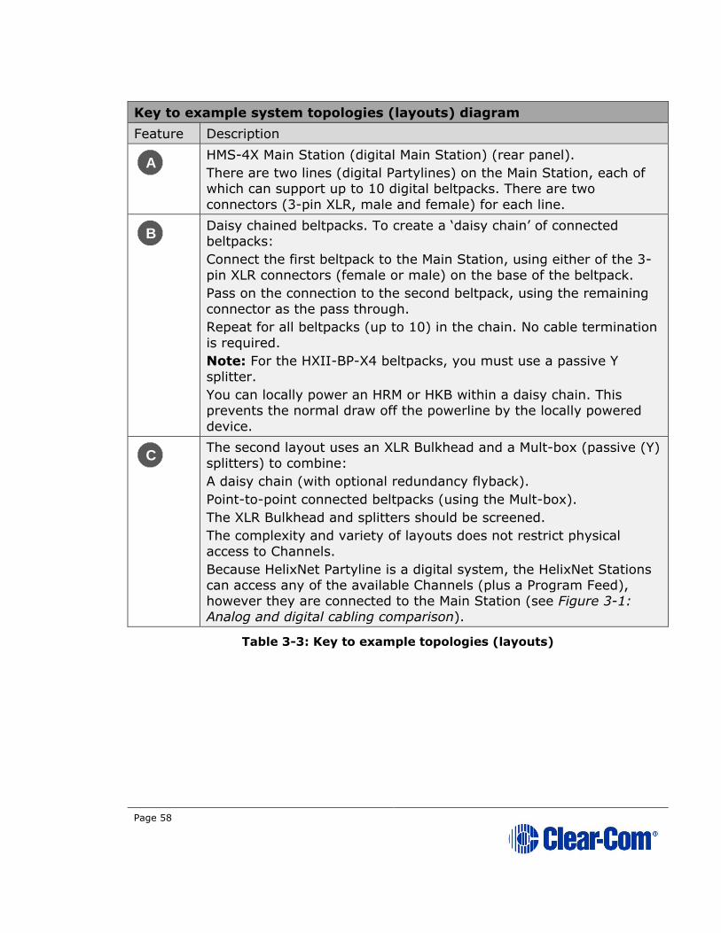
Key to example system topologies (layouts) diagram
Feature Description
A
HMS-4X Main Station (digital Main Station) (rear panel).
There are two lines (digital Partylines) on the Main Station, each of
which can support up to 10 digital beltpacks. There are two
connectors (3-pin XLR, male and female) for each line.
B
Daisy chained beltpacks. To create a ‘daisy chain’ of connected
beltpacks:
Connect the first beltpack to the Main Station, using either of the 3-
pin XLR connectors (female or male) on the base of the beltpack.
Pass on the connection to the second beltpack, using the remaining
connector as the pass through.
Repeat for all beltpacks (up to 10) in the chain. No cable termination
is required.
Note: For the HXII-BP-X4 beltpacks, you must use a passive Y
splitter.
You can locally power an HRM or HKB within a daisy chain. This
prevents the normal draw off the powerline by the locally powered
device.
C
The second layout uses an XLR Bulkhead and a Mult-box (passive (Y)
splitters) to combine:
A daisy chain (with optional redundancy flyback).
Point-to-point connected beltpacks (using the Mult-box).
The XLR Bulkhead and splitters should be screened.
The complexity and variety of layouts does not restrict physical
access to Channels.
Because HelixNet Partyline is a digital system, the HelixNet Stations
can access any of the available Channels (plus a Program Feed),
however they are connected to the Main Station (see Figure 3-1:
Analog and digital cabling comparison).
Table 3-3: Key to example topologies (layouts)

Page 59
3.2 Installing the Main Station/Remote Station
The Main Station/Remote Station is a 19” 1RU-height device that you can install
to either:
• A standard 19” rack.
• A shelf, cabinet or other flat surface.
3.2.1 Main Station power up
There is no power switch, button or key on the Main Station. To power up the
unit:
1) Connect the power cord to the power supply connector on the Main Station.
Note: The Main Station has a cable retaining clip to secure the power
cord. The retaining clip is detached for shipping and must be refitted.
Note: For the location of the power supply connector, see A in Table
2-12: Key to HMS-4X Main Station rear panel diagram and
Table 2-22: Key to Remote Station rear panel diagram.
2) Connect the power cord to the power source. The unit requires an input voltage between 100 - 240 VAC / 50-60Hz/ 250 watts / T 3.15A H 250 V.
Only connect power supply to earthed supply sockets. Ensure that the power supply is routed to avoid sharp bends, hot surfaces, pinches and abrasion.
For safety guidance, see the Safety Instructions at the front of this guide.
3.2.2 Remote Station power up
The Remote Station is powered by an external power source. This can be:
• An external power supply (supplied)
• Power over Ethernet (PoE)
Note: To use PoE, you must connect a third-party PoE switch between
the Remote Station and the Main Station.
• From the Main Station digital power line
Page 60
3.3 Installing the Speaker Station
The Speaker Station can be installed either:
• Mounted in an S-Mount bracket for desktop use
• Mounted in an S-Mount bracket for installation on a wall
• Mounted inside a NEMA standard 4-gang wall box.
Note: The S-Mount bracket is an optional item ordered separately.
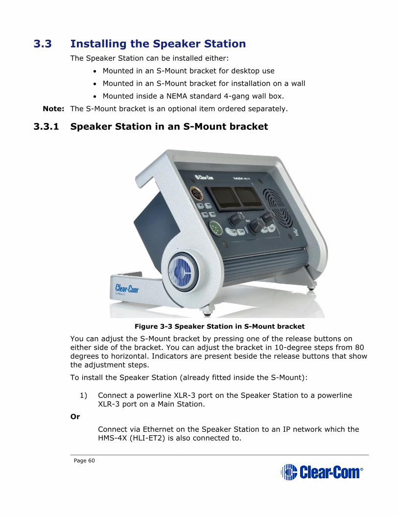
3.3.1 Speaker Station in an S-Mount bracket
Figure 3-3 Speaker Station in S-Mount bracket
You can adjust the S-Mount bracket by pressing one of the release buttons on
either side of the bracket. You can adjust the bracket in 10-degree steps from 80
degrees to horizontal. Indicators are present beside the release buttons that show
the adjustment steps.
To install the Speaker Station (already fitted inside the S-Mount):
1) Connect a powerline XLR-3 port on the Speaker Station to a powerline
XLR-3 port on a Main Station.
Or
Connect via Ethernet on the Speaker Station to an IP network which the
HMS-4X (HLI-ET2) is also connected to.
Page 61
2) Connect a headset or microphone to the Speaker Station.
3) Connect power supply to the DC power port on the Speaker Station. (Not necessary if using Powerline or PoE.)
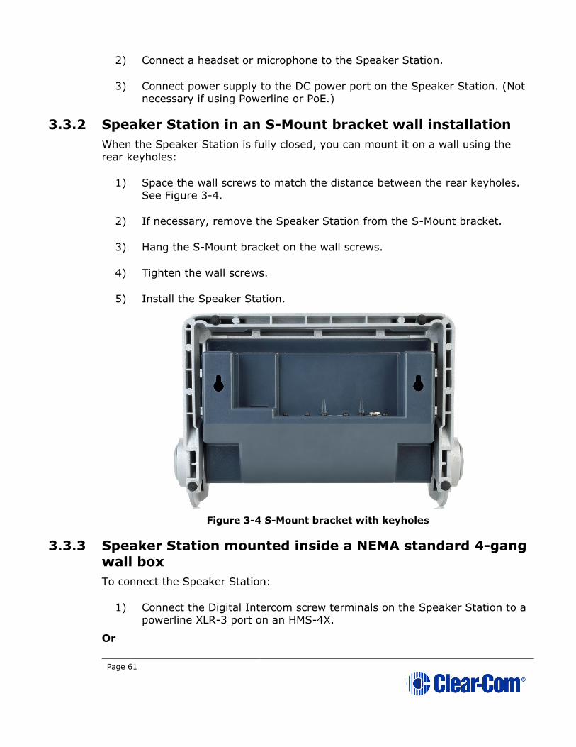
3.3.2 Speaker Station in an S-Mount bracket wall installation
When the Speaker Station is fully closed, you can mount it on a wall using the rear keyholes:
1) Space the wall screws to match the distance between the rear keyholes. See Figure 3-4.
2) If necessary, remove the Speaker Station from the S-Mount bracket.
3) Hang the S-Mount bracket on the wall screws.
4) Tighten the wall screws.
5) Install the Speaker Station.
Figure 3-4 S-Mount bracket with keyholes
3.3.3 Speaker Station mounted inside a NEMA standard 4-gang wall box
To connect the Speaker Station:
1) Connect the Digital Intercom screw terminals on the Speaker Station to a powerline XLR-3 port on an HMS-4X.
Or

Page 62
Connect the Ethernet port on the Speaker Station to either the IP network
in which the HMS resides or directly to one of the Ethernet ports on the
HMS.
2) Connect a headset or microphone to the Speaker Station.
3) If required, remove the connector from the optional power supply and connect the power supply to the Power screw terminals on the Speaker
Station.

Page 63
3.4 Installing the HBP-2X Beltpacks
The HBP-2X Beltpack is a device that you can:
• Wear at your belt using the beltclip.
• Install to a shelf or other flat surface.
• Attach to a pole or other fixed upright position.
For more information, see 2.5.3 HBP-2X beltclip, beltloops and feet (base view).
3.4.1 Power up
The HBP-2X Beltpack is powered from the standard mic cable that connects the
device with the HMS-4X Main Station (see below).
3.4.2 Connecting the HBP-2X Beltpack to the Main Station
To connect the HBP-2X Beltpack to the Main Station:
1) There are two powerline connections on the Main Station which can each support up to 10 digital HBP-2X Beltpacks. There are two connectors (3-
pin XLR, male and female) for each line.
Connect the cable to the selected connector on the Main Station.
Note: For the location of Lines 1 and 2 (the powerlines) on the Main
Station, see F G in Figure 2-3: HMS-4X Main Station: rear panel
2) Connect the cable to the beltpack, using one of the two 3-pin XLR connectors (male and female) on the base / rear of the beltpack.
For examples of topologies, see 3.1.2 Topologies.
3.5 Installing the HXII-BP-X4 Beltpacks
The HXII-BP-X4 Beltpack is a device that you can:
• Wear at your belt using the beltclip.
• Install to a shelf or other flat surface.
• Mount on a table or other flat surface.
For more information, see 2.6.4 HXII-BP-X4 Beltpack (beltloops and clip).
3.5.1 Power up
The HXII-BP-X4 Beltpack is powered from:

Page 64
• The standard microphone cable that connects the device with the HMS-
4X Main Station (see below).
• Power over Ethernet (PoE) using a cat5, 5e or 6 cable.
Note: To use PoE, you must connect a third-party PoE switch between the Main Station
and the HXII-BP-X4 Beltpack.
Note: You can power the HXII-BP-X4 over both microphone cable and PoE. In this case,
the PoE takes priority. After the beltpack boots up, you cannot switch between
PoE and powerline (microphone cable) mode.
3.5.2 Connecting the HXII-BP-X4 Beltpack over powerline to the Main Station
To connect the HXII-BP-X4 Beltpack to the Main Station:
1) There are two powerline connections on the Main Station which can each support up to 10 digital HXII-BP-X4 Beltpacks. There are two connectors
(3-pin XLR, male and female) for each line.
Connect the cable to the selected connector on the Main Station.
Note: For the location of Lines 1 and 2 (the powerlines) on the Main
Station, see F G in Figure 2-3: HMS-4X Main Station: rear panel
2) Connect the cable to the beltpack, using the 3-pin XLR connector on the base / rear of the beltpack.
For examples of topologies, see 3.1.2 Topologies.
3.5.3 Powering the HXII-BP-X4 using PoE
To connect the HXII-BP-X4 to the Main Station for PoE:
1) Connect the Main Station to a network switch using the HLI-ET2 Ethernet interface module.
2) Connect the HXII-BP-X4 Beltpack to the PoE switch on the same network as the Main Station.
Note: The beltpack must be paired to the Main Station.
Important:
When using an IEEE-802.3af compliant PoE switch, be sure to note the switch's
power budget. Each HXII-BP-X4 requires 4 Watts of power. Do not exceed the
power budget of the switch when attaching HXII-BP-X4 beltpacks.
Page 65
3.6 HelixNet infrastructure
This section contains guidelines for using HelixNet infrastructure components
including cables, connectors, splitter boxes and patch panels. HelixNet digital
Partyline uses cable infrastructure to transport audio and data over a range of
frequencies. The maximum frequency used for transmission is approximately
25MHz. Depending on the amount of audio and data transmitted, HelixNet digital Partyline can work with as much as 90dB signal attenuation. However, the
receivers are very sensitive and are susceptible to crosstalk between cables.
Therefore it is important to maintain cable shield integrity through all
connectors, splitter boxes and patch panels.
The symptoms of crosstalk are:
• Main Station front panel LINE LED indicator turns amber or red
• Beltpacks, Remote Stations and Speaker Stations take longer than usual
to boot and connect.
• Beltpack, Remote Station and Speaker Station front panel signal strength
indicators show lower than usual signal strength (zero or one bar).
• Main Station diagnostics screen (Diagnostics->Powerlines) indicates collisions or errors on the line.
3.6.1 Cables and connectors
Clear-Com recommends the following shielded cables:
Microphone cables
Belden 9207 and 9463F with the two main conductors connected to XLR pin 2 and 3 and the drain wire to pin 1.
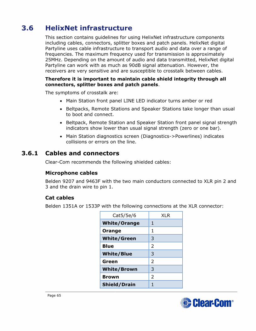
Cat cables
Belden 1351A or 1533P with the following connections at the XLR connector:
Cat5/5e/6 XLR
White/Orange 1
Orange 1
White/Green 3
Blue 2
White/Blue 3
Green 2
White/Brown 3
Brown 2
Shield/Drain 1

Page 66
It is important to connect the cable shield or drain wire to the XLR pin 1
to maintain the shield integrity throughout the cable and connector.
Note: The total amount of cable deployed for a digital intercom line contributes to the
total capacitance of the line, even though some cables might not have a beltpack
connected at the other end. The more capacitance there is, the more attenuation there will be. Clear-Com recommends that you use the minimum amount of cable.
For example, daisy-chain or split a cable at the far end, close to the beltpacks,
rather than make two homeruns to a central patch panel.
3.6.2 Patch panels
Clear-Com recommends XLR patch panels. These should be made of 3 pin XLR
feed-through adapters (for example, Neutrik NA3MDF) that maintain shield
integrity from the back to the front. These adapters also enable easier rewiring of
the back or the front of the panel.
3.6.3 Splitter boxes
Ensure that you split the digital intercom lines within a shielded enclosure. For
example, a 1RU shielded chassis, such as Middle Atlantic CH1, and daisy-chained
XLR connectors (for example, Neutrik NC3MD or NC3FD).
To prevent crosstalk between lines, ensure that each shielded splitter box contains only one digital intercom line. If you have to split more than one digital
intercom line, use multiple shielded enclosures.
For more information on cabling see 24.3 Cable connections
3.7 Converting analogue Partylines to HelixNet
Many Partyline installations use daisy-chained power terminal blocks to passively
split analog Partylines. This way of splitting works relatively well for one HelixNet
POWER LINE #1A
POWER LINE #1AWALL PLATE
POWER LINE #1B
POWER LINE #1BWALL PLATE
Page 67
Main Station. But because the cable shielding through those blocks is not
maintained, it makes the communication much more sensitive to interference.
Also, crosstalk occurs if two or more Main Stations use terminal blocks that are
close to each other.
To maintain shield integrity, Clear-Com recommends that you:
• Place existing terminal blocks in shielded and grounded enclosures
Or
• Replace the terminal blocks with shielded and grounded XLR splitter
boxes and XLR patch panels.

Page 68
4 IP Network Structure
4.1 Network connections
Connecting into an existing IP network requires planning with your IT department
in order to plan the IP addressing scheme. By default, HelixNet Main Station uses
automatic IP addressing (DHCP) enabled. In order for that to work properly in an existing IP network there must be a DHCP server handing out IP addresses. If no
DHCP server is found, a Main Station will revert to an unused link-local address in
the 169.254.0.0/16 block. (See 4.3 Link Local Environments for more
information).
Through the Networking menu on the devices, you can disable DHCP and set
static IP addresses.
Note: For HelixNet 3.0 and above, it is not necessary for Main Stations or Remote
Stations to be on the same Subnet, the devices will link across your LAN.
Figure 4-1: Network connections
4.2 Multiple Groups in the same IP Network
You can link three Main Stations together to form a Link Group. You must select
one of the Main Stations to be a Link Master. You can have multiple groups in the
same network by having multiple Link-Masters. Each Link-Master heads a group
of Main Stations, and does not interfere with other groups.

Page 69
Networking Specifications
Specification Value
Latency on Powerline 40-80ms (Depends on cable type and length, and how many devices are connected. The greater the
number of devices, the greater the latency).
Latency over IP Network 30ms + Network Latency (Main Station to Main
Station).
Bandwidth used 300 kbps per active Talker, for a maximum of one
talker per device in the system.
Each Beltpack and Speaker Station counts as one
device.
Each Main Station and Remote Station counts as
two devices.
Each HLI-2W2 or HLI-4W2 counts as two devices.
IP version IPv4
Table 4-1 Networking specifications
4.3 Link Local Environments
4.3.1 What is link-local?
A link-local address is an IP address within the local segment of any network.
Routers do not pass information to these as link-local addresses are not
guaranteed to be unique beyond a single network segment. When first connected
to a network, your HelixNet device will attempt to get an IP address via Dynamic Host Configuration Protocol (DHCP). If no DHCP server is available, the unit will
automatically enter link-local IP mode. A link-local IP address will take the form:
169.254.xxx.xxx.
4.3.2 Working with a device in link-local mode
Devices will revert to link-local mode if they are configured to DHCP and fail to
find a DHCP address on the network or device they are attempting to connect to.
Any DHCP enabled device connected directly to a device in link-local mode using a
standard Ethernet cable will enter link-local mode automatically.
Note: The HelixNet units will operate in link-local mode, but for optimum performance it
is recommended that they are used with either static or DHCP network settings. In link-local, the address will change each time the device reboots resulting in
potential loss of connection to endpoints.
The easiest way to take a HelixNet device out of link-local mode is to allocate a
new IP address to the unit from the device front menus. Please ensure with your
network administrator that there will be no IP clashes with this address.

Page 70
4.3.3 Change the IP address of a HelixNet device from the front
menu screens
To change a unit’s IP address, you must first disable DHCP. Press the Menu
button on front of device to enter Menu mode.
1) To enable or disable DHCP:
a) In Menu mode, select Networking.
Note: The Networking menu only appears if an Ethernet or Fiber
interface module is detected.
b) From the second menu, select Preferences.
c) From the third menu, select DHCP.
d) From the fourth display screen, select one of the following:
• Disabled
• Enabled (default)
2) To edit the IP address:
a) In Menu mode, select Networking.
Note: The Networking menu only appears if an Ethernet or Fiber
interface module is detected.
b) From the second menu, select Preferences.
c) From the third menu, select IP Address.
d) From the fourth display screen, edit the IPv4 address.
Note: The HelixNet system uses 10.0.0.x and 172.23.x.x IP address
ranges internally between the Main Station and the Beltpacks, and therefore will not allow setting the external IP address to anything
in that range.
Note: If you change the IP address (either manually or through DHCP),
the link between stations will be broken and you have to reboot
the Main Station to link again. The following message will appear as a banner (inverted text) at the bottom across the four displays
on the Main Station
IP address | changed, | reboot | to link
If that message appears, pressing the Menu key will bring you
directly to: Administration->Reset->Reboot->Reboot Now
4.3.4 Accessing the Core configuration Manager (CCM) of a
HelixNet unit in link-local mode
As an alternative to configuring your device from the front menu screens you can use the browser based CCM.
Page 71
To access the CCM of a HelixNet unit in link-local, you must connect to it from a
computer that is also in link-local mode.
A computer can be put into link-local mode by ensuring it is in DHCP mode and
connecting it to a unit that is already in link-local mode with a standard Ethernet
cable. The computer will look for a dynamically generated IP address (DHCP), and when it does not find one will enter link-local mode automatically.
Once the computer is connected to the HelixNet device and in link-local mode,
you can connect to your unit by opening a browser window on the computer and
inputting the unit’s IP address (from the front panel display) into the address
field. This takes you to the Core Configuration Manager where you can configure the device as usual. See 14 Core Configuration Manager (CCM) for more detail.
Note: The units will operate in link-local, but for optimum performance it is
recommended that they are used with either static or DHCP network settings.
Note: The default username/password is Admin/Admin.

Page 72
5 Configuring and managing the Main Station
from front menus
This chapter describes how to configure the settings and manage the Main Station
using Menu mode. It also shows you how to monitor and diagnose performance
issues, using the Diagnostics menus.
Tip: For a quick reference to the Main Station menus, see 22 Menu maps.
5.1 Using the Menus
To place the Main Station in Menu mode, press the Menu key to the left of the
first display screen.
In Menu mode, the display screens display the four levels of menu. The menu
hierarchy proceeds left to right:
• The top level menu is presented in the first screen.
• The lowest level menu is presented in the fourth screen (furthest right
on the front panel).
Note: If Menu mode is locked, you must unlock the menus from CCM before you can enter the menu. See 5.7 Administration.
5.1.1 Configuring settings
To configure settings:
1) For each menu, turn the rotary control clockwise to scroll down the menu items. Turn counter clockwise to scroll up the menu items.
Off-screen menu items are indicated by arrows at the top and/or bottom of the screen.
Selected menu items (which create your path through the four menus)
are highlighted in solid yellow.
The fourth menu displays the settings that relate to your previous menu
choices (system features or functionality).
The current setting is indicated by a dotted box around the menu item
2) When you have selected a setting by rotating the right hand rotary control, push that rotary control to enable the setting on the Main
Station.
5.1.2 Exiting Menu mode
To exit menu mode press the menu key.
Note: If no key is pressed for 20 seconds, the menu will time out and display screens
will revert to their normal mode of operation.
Page 73
5.2 Configuring the Audio settings
5.2.1 Audio settings for the headset
To configure the audio settings for the headset:
1) In Menu mode, select Audio Settings and then Headset.
2) To adjust the level of sidetone on the headset:
a) In the third menu, select Sidetone Gain.
b) In the fourth menu, select one of the following:
• 0dB
• - 6dB
• - 12dB (default)
• - 18dB
c) To enable (confirm) the selected setting, press the rotary control.
3) To limit the audio level delivered to the headphones (or to disable headphone limiting):
a) In the third menu, select Headphone Limit.
b) In the fourth menu, select one of the following:
• Off
• +6dB
• 0dB (default)
• - 6dB
c) To confirm the selected setting, press the rotary control.
Note: When Headphone Limit is set to anything but Off, a LIM indication
will be shown on the leftmost display.
4) To set the Headphone Gain:
a) In the third menu, select Headphone Gain.
b) In the fourth menu, select one of the following:
• OdB (default)
• +3dB
• +6dB
• +9dB
• +12dB

Page 74
c) To confirm the selected setting, press the rotary control.
5) To set (or disable) sidetone tracking on the headset:
a) In the third menu, select Sidetone Control.
b) In the fourth menu, select one of the following:
• Tracking - The sidetone volume will follow (track) the Main
volume level.
• Non-Tracking - The sidetone volume is set to use the selected level.
• Disabled - Sidetone is disabled.
Note: The default is Tracking.
c) To confirm the selected setting, press the rotary control.
6) To select the type of microphone on the headset:
a) In the third menu, select HS Mic Type.
Note: HS = Headset.
b) In the fourth menu, select either of the following types of
microphone:
• Electret (-15dB)
• Dynamic (0dB) (default)
• Dynamic (low)
c) To confirm the selected setting, press the rotary control.
5.2.2 Audio settings for the microphone
To configure the audio settings for the microphone:
1) In Menu mode, select Audio Settings and then Microphone.
2) To select the Headroom:
a) From the third menu, select Headroom.
b) From the fourth menu, select one of the following:
• Normal (default)
• High - Reduces the analog input gain and increases the digital
gain accordingly. That reduces digital clipping at the A/D
converter but increases the noise floor. This setting is intended
for use in environments with very high background noise.

Page 75
3) To enable or disable the Contour Filter:
a) From the third menu, select Contour Filter
b) From the fourth menu, select one of the following:
• Enabled - The Contour filter is a Clear-Com algorithm
enhancing speech intelligibility, especially when whispering or talking at a low volume.
• Disabled
Note: The default is Disabled.
5.2.3 Audio setting for the Program Input
To configure the label (name) for the Program Input (Program Feed) gain:
1) In Menu mode, select Audio Settings and then Program Input.
2) From the third menu, select Label.
3) From the fourth menu, select the existing label by scrolling to it and
pushing the rotary controller. Edit the label by rotating the controller to scroll through letters and digits and pushing to select a letter/digit.
4) When you have done, scroll to Save and push the rotary controller. To exit without saving changes, go back to the third screen.
To configure the audio setting for the Program Input (Program Feed) gain:
5) In Menu mode, select Audio Settings and then Program Input.
6) From the third menu, select Gain.
7) From the fourth menu, select one of the following:
• + 12dB
• + 6dB
• 0dB (default)
• - 6dB
• - 12dB
8) To confirm the selected setting, press the rotary control.
Page 76
9) The GPO trigger activates a relay when receiving a call or activating a talk on a Partyline Channel. You can enable or disable the GPO trigger. To
configure the audio setting for the GPO trigger:
1) In Menu mode, select Audio Settings and then Program Input.
2) From the third menu, select GPO Trigger.
3) From the fourth menu, select one of the following:
• Enabled (default)
• Disabled
4) To confirm the selected setting, press the rotary control.
Note: You can also configure the GPO trigger using Menu Mode >
Modules Settings.
To select the VOX:
1) From the third menu, select VOX.
a) From the fourth menu, select one of the following:
• Enabled
• Disabled (default)
2) To confirm the selected setting, press the rotary control.
To select the VOX Off Delay:
1) From the third menu, select VOX Off Delay.
2) From the fourth menus, select one of the following:
• .5 sec (default)
• 1 sec
• 2 sec
• 3 sec
• 4 sec
3) To confirm the selected setting, press the rotary control.
5.2.4 Audio settings for Program IFB [Interruptible Foldback]
IFB allows you to temporarily interrupt the continuous program listen (program
feed) and speak to the Channels connected to the program listen. This applies to
a Channel to which the Program Input is assigned. If any participant within the
Page 77
Channel talks, the program is dimmed. See also 5.4.2 Assigning the Program
Listen to a Channel.
To configure the audio settings for Program IFB [Interruptible Foldback]:
1) In Menu mode, select Audio Settings and then Program IFB.
2) From the third menu, select IFB Dim Level.
Note: The IFB Dim Level determines the amount that the volume level of
the Program Level is reduced by when it is interrupted by the IFB.
3) From the fourth menu (fourth display screen), select one of the following:
• IFB Disabled (default)
• - 6dB
• -12dB
• -18dB
• -24dB
• Full Cut
4) To confirm the selected setting, press the rotary control.
5.2.5 Audio settings for the SA [Stage Announce] Output
To configure the audio settings for the SA [Stage Announce] Output:
1) In Menu mode, select Audio Settings and then SA Output.
2) From the third menu, select Gain.
3) From the fourth menu, select one of the following:
• + 12dB
• + 6dB
• 0dB (default)
• - 6dB
• - 12dB
4) To confirm the selected setting, press the rotary control.

Page 78
5.2.6 Audio settings for the Hot Mic Output
To configure the audio settings for the Hot Mic Output:
1) In Menu mode, select Audio Settings and then Hot Mic Output.
2) From the third menu, select Gain.
3) From the fourth menu, select one of the following:
• + 12dB
• + 6dB
• 0dB (default)
• - 6dB
• -12dB
4) To confirm the selected setting, press the rotary control.
5.2.7 Audio settings for the Front Panel
To configure the audio settings for the Front Panel:
1) In Menu mode, select Audio Settings and then Front Panel.
2) From the third menu, select Loudspeaker Dim.
3) From the fourth menu, select one of the following:
• 0 dB
• -3 dB
• -6 dB (default)
• -12 dB
• -24 dB
4) To confirm the selected setting, press the rotary control.
Page 79
5.3 Selecting Station Settings
5.3.1 Setting Preferences
To set the Preferences:
1) In Menu mode, select Station Settings and then Preferences. You will see Roles in the third menu.
2) From the fourth menu, select the required Role. Select local config if you do not wish to use a role.
3) To confirm the selected setting, press the rotary control.
5.3.2 Setting Keyset Assignments
To set the Keyset Assignments:
1) In Menu mode, select Station Settings and then Keyset Assign.
2) From the third menu, select required Keyset (1 – 4).
3) From the fourth menu, select a Channel (1 – 24) to assign to the Keyset.
4) Repeat this procedure for the remaining Keysets.
5) To confirm the selected setting, press the rotary control.
5.3.3 Setting key latching
To enable or disable front panel keys for latching:
1) In Menu mode, select Station Settings and then Keysets.
2) From the third menu, select either:
Key(s) Description
Talk #1 Talk keys for the available Channels.
Talk #2
Talk #3
Talk #4
SA Out key Key used to talk to a connected public address or Stage Announce (SA) system.
Table 5-1: Setting key latching

Page 80
Note: The All Talk and RMK (Remote Mic Kill) key are also displayed in
the list. Those keys cannot be latched. To find out how to
configure the RMK and All Talk keys, see 5.3.5 Setting the All
Talk key.
Note: The All Talk key allows you to talk to all Channels at once with the push of a button. Select All Channels to talk to all 12 (or 24
according to license) Channels on your system. Select Visible
Channels to talk to the Channels visible on your four device
Keyset screens.
3) In menu mode select Station Settings and then Keysets.
4) From the third menu, select All Talk.
5) From the fourth menu, select All Channels or Visible Channels.
6) To confirm the selected setting, press the rotary control.
5.3.4 Setting the All Talk key
The All Talk key allows you to talk to all Channels at once with the push of a button. Select All Channels to talk to all 12 (or 24 according to license) Channels
on your system. Select Visible Channels to talk to the Channels visible on your
four device Keyset screens.
1) In menu mode select Station Settings and then Keysets.
2) From the third menu, select All Talk.
3) From the fourth menu, select All Channels or Visible Channels.
4) To confirm the selected setting, press the rotary control.
5.3.5 Setting the RMK (Remote Mic Kill) key
The RMK (Remote Mic Kill) key is used to:
• Deselect any latched keyset Talk routes.
• Turn off any latched Talk on connected analog Partyline equipment.
To enable or disable the RMK (Remote Mic Kill) key:
1) In Menu mode, select Station Settings and then Keysets.
2) From the third menu, select RMK.
Page 81
Note: Talk Latch and the SA Output Key are also listed in this menu.
See 5.3 Selecting Station Settings.
3) From the fourth menu, select either of the following:
• All Channels (12 or 24 according to license)
• Visible Channels (default)
• Disabled
4) To confirm the selected setting, press the rotary control.
5.3.6 Setting display screen brightness
By default, the display screens are set for medium brightness. To set the
brightness of the display screens:
1) In Menu mode, select Station Settings and then Display.
2) From the third menu, select OLED Brightness.
3) From the fourth menu, select one of the following brightness settings:
• High
• Medium (default)
• Low
4) To confirm the selected setting, press the rotary control.
5.3.7 Setting key brightness
By default, the front panel keys are set to High / Low. To set the brightness of
all front panel keys:
1) In Menu mode, select Station Settings and then Display.
2) From the third menu, select Key Brightness.
3) From the fourth menu, select one of the following brightness settings:
Key(s) Description
High / Low The default setting.
Keys are lit bright when active and lit dim when
inactive.
High / Off Keys are lit bright when active and are unlit when
inactive.

Page 82
Low / Off Keys are lit dim when active and are unlit when
inactive.
Off / Off Keys are unlit, whether or not they are active or
inactive.
Table 5-2: Setting key brightness
4) To confirm the selected setting, press the rotary control.
5.3.8 Setting the screensaver
The screensaver features the Channel label and is enabled by default. The display
screens enter screensaver mode when the Main Station has been inactive for 10
minutes.
Tip: To exit screensaver mode, press any key on the front panel.
To enable or disable the screensaver:
1) In Menu mode, select Station Settings and then Display.
2) From the third menu, select Screensaver.
3) From the fourth menu, select:
• Channel Name (default)
• Hostname
• Role Name
• Blank
• Disabled
4) To confirm the selected setting, press the rotary control.
Page 83
5.4 Configuring the Channel settings
5.4.1 Editing the Channel label
The maximum length for a Channel label is 12 characters.. To edit the Channel
label:
Note: Channel labels will be dictated by the Link Master when Main Stations are linked.
1) In Menu mode, select Channels and then the name of the Channel you
want to edit.
2) From the third menu, select Label.
3) Select Clear and press the rotary control to clear the Channel label.
4) In the fourth menu, the following prompt is displayed above the Channel label:
[Press to edit]
Press the rotary control.
5) The first letter of the Channel label is shown as selected. The following prompt is displayed above the Channel label:
[Scroll / Press to Select]
Scroll to the character you want to edit by turning the rotary control. To
begin editing, press the rotary control.
6) The character you have selected for editing is shown in a box with a
dotted border.
To display alternative characters in the box, turn the rotary control. The
range of available characters comprises the following:
Characters Description / range
Numbers
(numeric)
0 to 9
Letters Capital letters = A to Z
Small letters = a to z
Symbols # & * ( ) - _ = + / ! @ :
Note: You can also select a space.
Table 5-3: Channel label characters
To select a character, press the rotary control.
Page 84
7) When you have selected a replacement character, scroll to the next character you want to edit. When you have finished editing the Channel
label, scroll to Save (displayed beneath the Channel label).
To save the Channel label, press the rotary control.
5.4.2 Assigning the Program Listen to a Channel
To assign (or unassign) the Program Listen (Program Feed) to a Channel:
1) In Menu mode, select Channels and then the name of the Channel.
2) From the third menu, select Program Listen.
3) From the fourth menu, select either None, or choose from the list of available programs.
Note: The default is None.
4) To confirm the selected setting, press the rotary control.
Tip: When you assign the Program Listen to a Channel, PGM is displayed on the display screen (under the listen level bar, to the left) for that Channel.
5.4.3 Assigning a GPO relay to a Channel
You can assign a relay that is triggered on receiving a call or detecting a talk on a Partyline Channel. To assign (or unassign) a relay:
1) In Menu mode, select Channels and then the name of the Channel.
2) From the third menu, select GPO on Talk or GPO on Call.
3) From the fourth menu, select either None, or choose from the list of available relays.
Note: The default is None.
4) To confirm the selected setting, press the rotary control.
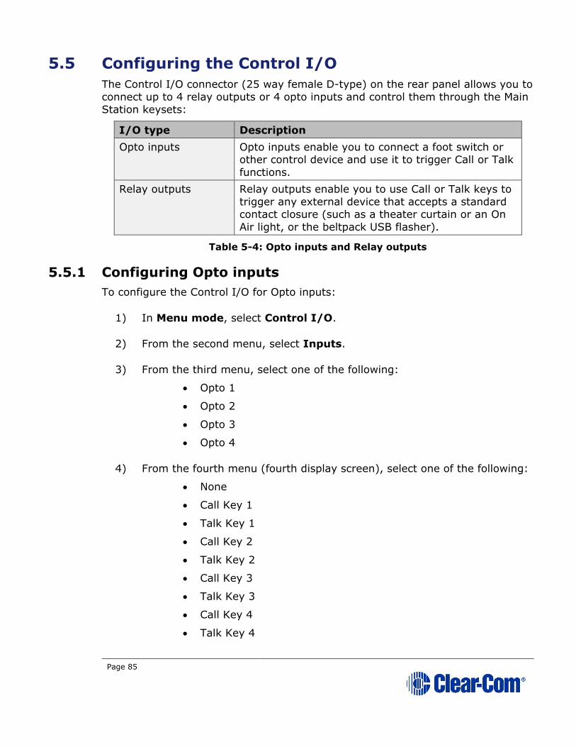
Page 85
5.5 Configuring the Control I/O
The Control I/O connector (25 way female D-type) on the rear panel allows you to
connect up to 4 relay outputs or 4 opto inputs and control them through the Main
Station keysets:
I/O type Description
Opto inputs Opto inputs enable you to connect a foot switch or other control device and use it to trigger Call or Talk
functions.
Relay outputs Relay outputs enable you to use Call or Talk keys to
trigger any external device that accepts a standard contact closure (such as a theater curtain or an On
Air light, or the beltpack USB flasher).
Table 5-4: Opto inputs and Relay outputs
5.5.1 Configuring Opto inputs
To configure the Control I/O for Opto inputs:
1) In Menu mode, select Control I/O.
2) From the second menu, select Inputs.
3) From the third menu, select one of the following:
• Opto 1
• Opto 2
• Opto 3
• Opto 4
4) From the fourth menu (fourth display screen), select one of the following:
• None
• Call Key 1
• Talk Key 1
• Call Key 2
• Talk Key 2
• Call Key 3
• Talk Key 3
• Call Key 4
• Talk Key 4

Page 86
5) To confirm the selected setting, press the rotary control.
5.5.2 Configuring Relay outputs
To configure the Control I/O for Relay outputs:
1) In Menu mode, select Control I/O.
2) From the second menu, select Outputs.
3) From the third menu, select one of the four available Relay outputs:
• Relay 1
• Relay 2
• Relay 3
• Relay 4
4) From the fourth menu, select one of the following:
• None (default)
• Call Key 1
• Talk Key 1
• Call Key 2
• Talk Key 2
• Call Key 3
• Talk Key 3
• Call Key 4
• Talk Key 4
• SA Key
Note: The number of the key relates to the keyset to which it belongs (for example, Call Key 1 is the Call key for the first keyset /
display screen).
5) To confirm the selected setting, press the rotary control.

Page 87
5.6 Configuring Module Settings
Up to three optional interface modules can be fitted to the expansion bay of the
HMS-4X Main Station.
Warning: The interface modules are not hot pluggable. Ensure that the
Main Station is powered down before inserting or removing modules.
The Menu mode > Module Settings are used to set up the interface modules.
Tip: For more detailed information about interface modules, including pin out
information, see: 2.2.1 HMS-4X Main Station rear panel: Interface modules.
5.6.1 Configuring a Four-wire interface module
The following procedure shows you how to configure the Module Settings for a
Four-wire interface module.
To configure the Module Settings for a four-wire interface module:
1) In Menu mode, select Module Settings.
2) From the second menu, select one of the two available ports on the two-wire interface module:
Slot 2/Port A 4W
Slot 2/Port B 4W
Note: In this example, the four-wire module has been fitted to slot 2 in
the expansion bay. The expansion bay contains three slots.
4W = four-wire.
3) To associate any available Channel with the selected port, or to disable
Channels associations:
a) From the third menu, select Channel Assign.
b) From the fourth menu, select one of the following:
• Disabled (default)
• Channel 1.
• Channel 2.
• Channel 3.
• Channel 4.
• …
c) To confirm the selected setting, press the rotary control.

Page 88
4) The Program Output allows a program feed associated with the Channel assigned to the four wire port to either be delivered to that 4 wire port
alongside the other Channel audio or not. To set the Program Output:
a) From the third menu, select Program Output.
b) From the fourth menu, select one of the following:
• Unmute
• Mute (default)
5) To confirm the selected setting, press the rotary control.
6) To set the input level for the four-wire port:
a) From the third menu (third display screen), select Input Gain.
b) From the fourth menu (fourth display screen), select one of the
following:
• +12dB
• + 6dB.
• 0dB (default)
• -6dB.
• -12dB
c) To confirm the selected setting, press the rotary control.
7) To set the output level for the four-wire port:
a) From the third menu, select Output Gain.
b) From the fourth menu, select one of the following:
• +12dB
• + 6dB.
• 0dB (default)
• -6dB.
• -12dB
8) To confirm the selected setting, press the rotary control.
9) To set the GPO trigger for the Program Output:
a) From the third menu, select GPO.
b) From the fourth menu, select one of the following:
• Enabled
• Disabled
Page 89
10) If you are setting up a continuous audio (program) feed using the four-wire interface module, then you may want to enable the VOX
functionality. To help reduce redundant noise, the VOX functionality
automatically deactivates and activates the continuous audio feed, at an
automatically determined volume threshold.
Note: If you assign a program and a four-wire interface to the same
Channel, VOX is automatically enabled.
To enable or disable VOX:
a) From the third menu, select VOX.
b) From the fourth menu, select one of the following:
• Enabled.
• Disabled (default)
c) To confirm the selected setting, press the rotary control.
11) The VOX Delay OFF setting determines the length of time to wait before deactivating the incoming audio. To set the VOX Delay OFF setting:
a) From the third menu, select VOX Delay OFF.
b) From the fourth menu, select one of the following:
• .5 sec (default)
• 1 sec
• 2 sec
• 3 sec
• 4 sec
c) To confirm the selected setting, press the rotary control.
5.6.2 Configuring a Two-wire interface module
The following procedure shows you how to configure the Module Settings for a
Two-wire interface module.
Note: The Two-wire interface module must receive power from the Partyline.
To configure the Module Settings for a Two-wire interface module:
1) In Menu mode, select Module Settings.

Page 90
2) From the second menu, select one of the two available ports on the two-wire interface module:
Slot 1/Port A 2W
Slot 1/Port B 2W
Note: In this example, the two-wire module has been fitted to slot 1 in
the expansion bay. The expansion bay contains three slots.
2W = Two-wire.
a) To associate any available Channel (or to disable Channels
associations) with the selected port: From the third menu (third display screen), select Channel Assign.
b) From the fourth menu, select one of the following:
• Disabled (default)
• Channel 1
• Channel 2
• Channel 3
• Channel 4
• …
c) To confirm the selected setting, press the rotary control.
3) The Program Output allows a program feed associated with the Channel assigned to the four wire port to either be delivered to that 4 wire port
alongside the other Channel audio or not. To set the Program Output:
a) From the third menu, select Program Output.
b) From the fourth menu, select one of the following:
• Unmute
• Mute (default)
4) To confirm the selected setting, press the rotary control.
5) Auto-nulling helps to reduce echo while talking on a two-wire audio system. To start Auto-nulling on the selected port:
a) From the third menu, select Auto-Nulling.
b) From the fourth menu, select Start.
Note: Auto-nulling is only applicable to two-wire audio. All Talk
routes/keys must be disabled before Auto-nulling can commence.
If an echo persists, ensure all Talk routes are disabled and re-null
the system.
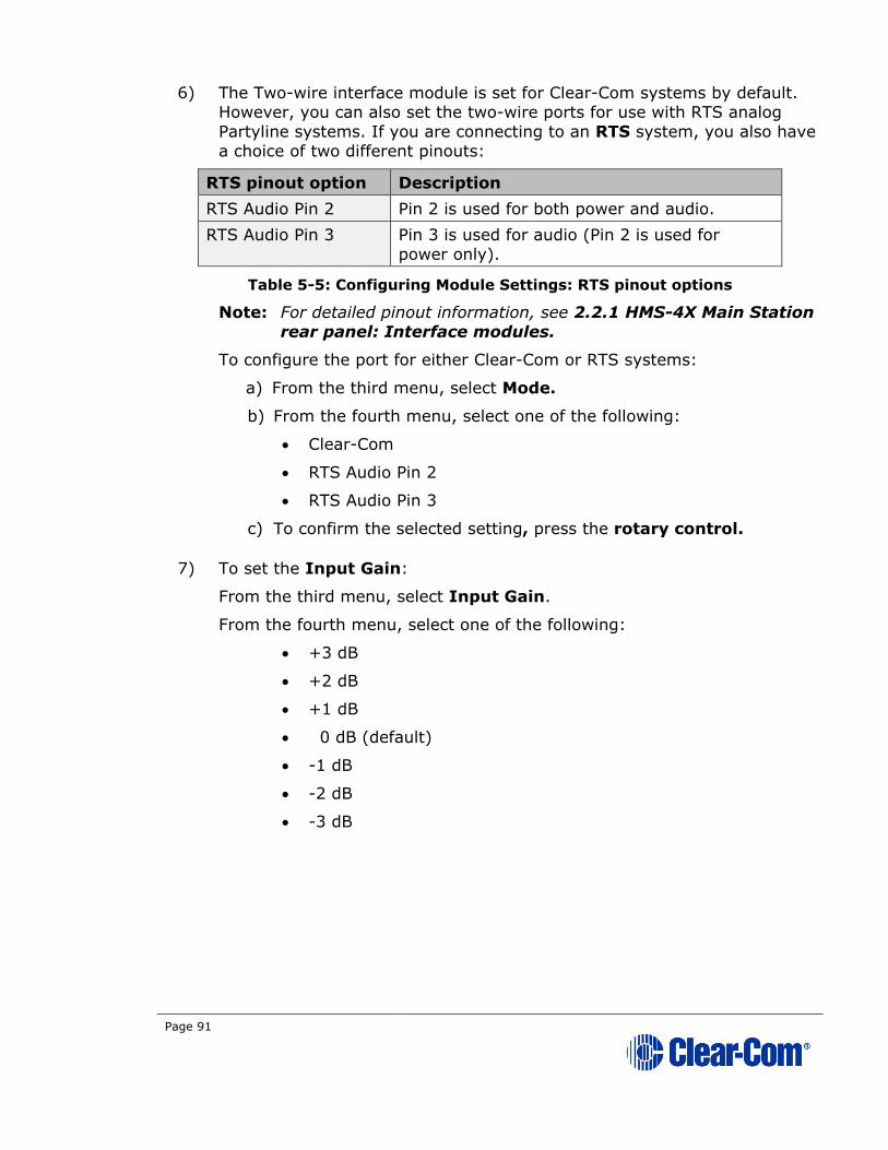
Page 91
6) The Two-wire interface module is set for Clear-Com systems by default. However, you can also set the two-wire ports for use with RTS analog
Partyline systems. If you are connecting to an RTS system, you also have
a choice of two different pinouts:
RTS pinout option Description
RTS Audio Pin 2 Pin 2 is used for both power and audio.
RTS Audio Pin 3 Pin 3 is used for audio (Pin 2 is used for
power only).
Table 5-5: Configuring Module Settings: RTS pinout options
Note: For detailed pinout information, see 2.2.1 HMS-4X Main Station
rear panel: Interface modules.
To configure the port for either Clear-Com or RTS systems:
a) From the third menu, select Mode.
b) From the fourth menu, select one of the following:
• Clear-Com
• RTS Audio Pin 2
• RTS Audio Pin 3
c) To confirm the selected setting, press the rotary control.
7) To set the Input Gain:
From the third menu, select Input Gain.
From the fourth menu, select one of the following:
• +3 dB
• +2 dB
• +1 dB
• 0 dB (default)
• -1 dB
• -2 dB
• -3 dB
Page 92
8) To set the Output Gain:
a) From the third menu, select Output Gain.
b) From the fourth menu, select one of the following:
• +3 dB
• +2 dB
• +1 dB
• 0 dB (default)
• -1 dB
• -2 dB
• -3 dB
9) To set the GPO trigger for the Program Output:
c) From the third menu, select GPO.
d) From the fourth menu, select one of the following:
• Enabled
• Disabled
10) Enabling RMK [Remote Mic Kill] Input allows an external 2-wire analogue partyline device such as the main (base) station (MS-702) to
send an RMK signal to the digital HelixNet devices attached to the same
HelixNet channel.
Note: If this is enabled and the analog Partyline system is powered
down, it will be interpreted by the HelixNet Main Station as an RMK
input and all talk routes will be switched off.
To enable RMK Input:
a) From the third menu (third display screen), select RMK Input.
b) From the fourth menu (fourth display screen), select one of the
following:
• Enabled
• Disabled (default)
c) To confirm the selected setting, press the rotary control.
11) Enabling RMK [Remote Mic Kill] Output allows you to send an RMK signal from the HelixNet Main Station to any connected analog 2-wire partyline system.
To enable RMK Output:
a) From the third menu, select RMK Output.
Page 93
b) From the fourth menu, select one of the following:
• Enabled
• Disabled (default)
To confirm the selected setting, press the rotary control.
12) If you are setting up a continuous audio (program) feed using the two-wire interface module, then you may want to enable the VOX
functionality. To help reduce redundant noise, the VOX functionality automatically deactivates and activates the continuous audio feed, at an
automatically determined volume threshold.
Note: If you assign a program and a two-wire interface to the same
Channel, VOX is automatically enabled.
To enable or disable VOX:
a) From the third menu, select VOX.
b) From the fourth menu, select one of the following:
• Enabled
• Disabled (default)
c) To confirm the selected setting, press the rotary control.
13) The VOX Delay OFF setting determines the length of time to wait before
deactivating the incoming audio. To set the VOX Delay OFF setting:
a) From the third menu, select VOX Delay OFF.
b) From the fourth menu, select one of the following:
• .5 sec (default)
• 1 sec
• 2 sec
• 3 sec
• 4 sec
c) To confirm the selected setting, press the rotary control.
5.6.3 Configuring an Ethernet or Fiber interface module
The following procedure shows you how to configure the Module Settings for an
Ethernet interface module.
To configure the Module Settings for an Ethernet interface module:
1) To view status information about Main Stations:
a) In Menu mode, select Networking.
Page 94
Note: The Networking menu only appears if at least one Ethernet or
Fiber interface module is detected.
b) From the second menu, select Stations. A list of station IDs is
given for each Main Station in the network. Each station ID in the
list is preceded by the letter M- for the Link-Master station itself and S- for all Link-Member (S stands for Slave).
c) From the third menu select the required station ID.
d) From the fourth menu you can view the following:
• Status – Enabled or Disabled
• IP – The IP address.
2) To edit or change the Hostname for your device:
a) In Menu mode, select Networking.
b) From the second menu, select Preferences
c) From the third menu, select Hostname
d) From the fourth menu, select the name by pushing and turning the
Rotary controller.
e) Edit the name by turning the controller to select a letter or number and pushing to select it. Then turn to scroll through letters. Push to
commit.
f) When you have done, scroll to SAVE and push to commit.
3) To enable or disable DHCP:
a) In Menu mode, select Networking.
Note: The Networking menu only appears if an Ethernet or Fiber
interface module is detected.
b) From the second menu, select Preferences.
c) From the third menu, select DHCP.
d) From the fourth display screen, select one of the following:
• Disabled
• Enabled (default)
4) To edit the IP address:
a) In Menu mode, select Networking.
Note: The Networking menu only appears if an Ethernet or Fiber
interface module is detected.
b) From the second menu, select Preferences.
Page 95
c) From the third menu, select IP Address.
d) From the fourth display screen, edit the IPv4 address.
Note: You can only edit the IPv4 address if DHCP is disabled.
Note: The HelixNet system uses 10.0.0.x and 172.23.x.x IP address
ranges internally between the Main Station and the Beltpacks, and therefore will not allow setting the external IP address to anything
in that range.
Note: If you change the IP address (either manually or through DHCP),
the link between stations will be broken and you have to reboot
the Main Station to link again. The following message will appear as a banner (inverted text) at the bottom across the four displays
on the Main Station
IP address | changed, | reboot | to link
If that message appears, pressing the Menu key will bring you
directly to: Administration->Reset->Reboot->Reboot Now
5) To edit the Gateway:
a) In Menu mode, select Networking.
Note: The Networking menu only appears if an Ethernet or Fiber
interface module is detected.
b) From the second menu, select Preferences.
c) From the third menu, select Gateway.
d) From the fourth display screen, edit the gateway.
Note: You can only edit the gateway if DHCP is disabled.
6) To edit the Subnet Mask:
a) In Menu mode, select Networking.
Note: The Networking menu only appears if an Ethernet or Fiber
interface module is detected.
b) From the second menu, select Preferences.
c) From the third menu, select Subnet Mask.
d) From the fourth display screen, edit the Subnet Mask.
Note: You can only edit the Subnet Mask if DHCP is disabled.
7) To enable or disable linking:
a) In Menu mode, select Networking.
Note: The Networking menu only appears if an Ethernet or Fiber
interface module is detected.
b) From the second menu, select Linking.
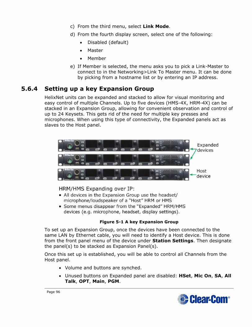
Page 96
c) From the third menu, select Link Mode.
d) From the fourth display screen, select one of the following:
• Disabled (default)
• Master
• Member
e) If Member is selected, the menu asks you to pick a Link-Master to
connect to in the Networking>Link To Master menu. It can be done
by picking from a hostname list or by entering an IP address.
5.6.4 Setting up a key Expansion Group
HelixNet units can be expanded and stacked to allow for visual monitoring and
easy control of multiple Channels. Up to five devices (HMS-4X, HRM-4X) can be
stacked in an Expansion Group, allowing for convenient observation and control of
up to 24 Keysets. This gets rid of the need for multiple key presses and
microphones. When using this type of connectivity, the Expanded panels act as slaves to the Host panel.
Figure 5-1 A key Expansion Group
To set up an Expansion Group, once the devices have been connected to the same LAN by Ethernet cable, you will need to identify a Host device. This is done
from the front panel menu of the device under Station Settings. Then designate
the panel(s) to be stacked as Expansion Panel(s).
Once this set up is established, you will be able to control all Channels from the
Host panel.
• Volume and buttons are synched.
• Unused buttons on Expanded panel are disabled: HSet, Mic On, SA, All
Talk, OPT, Main, PGM.
Page 97
Restrictions:
• Devices can only connect as an Expansion Group over LAN, not when
connected over digital Partyline.
• HMS-4X or HRM-4X can act as Host Panel.
• HMS-4X can only act as a key Expansion Panel to another HMS-4X.
• HRM-4X can act as a Key Panel to an HMS-4X and an HRM-4X.
• If an HRM-4X is already Paired to an HMS-4X, it will only see Host Panels
that are part of the same group.
• If an HRM-4X is not Paired yet to an HMS-4X, it will see all Host Panels in
the subnet and will automatically Pair at the same time if a Host Panel is selected.
• An Expansion Group must be set up from the device menus, and cannot
be set up from the CCM.
To set up a key Expansion Group (example set-up)
Designate the expansion Host unit:
1) On the Host device, press the MENU button to enter menu mode.
Note: For each menu, turn the rotary control clockwise to scroll down
the menu items. Turn counter clockwise to scroll up the menu
items.
Off-screen menu items are indicated by arrows at the top and/or
bottom of the screen.
Selected menu items (which create your path through the four
menus) are highlighted in solid yellow.
The current setting is indicated by a dotted box around the menu item
When you have selected a setting by rotating the right hand rotary
control, press that rotary control to enable the setting on the
Main Station.
2) Navigate to Menu > Networking > Expansion Mode. Select Host.
3) From the 4th screen on the device select Enabled. The device will then be open for expansion.
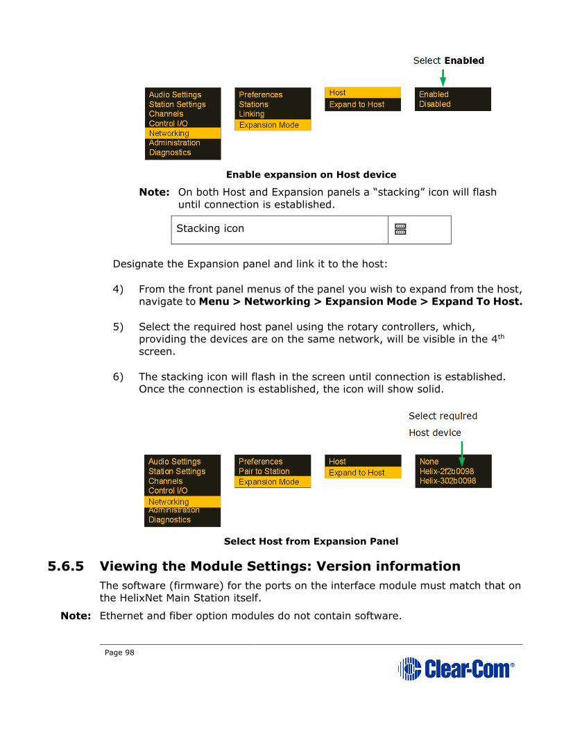
Page 98
Enable expansion on Host device
Note: On both Host and Expansion panels a “stacking” icon will flash
until connection is established.
Stacking icon
Designate the Expansion panel and link it to the host:
4) From the front panel menus of the panel you wish to expand from the host, navigate to Menu > Networking > Expansion Mode > Expand To Host.
5) Select the required host panel using the rotary controllers, which, providing the devices are on the same network, will be visible in the 4th
screen.
6) The stacking icon will flash in the screen until connection is established. Once the connection is established, the icon will show solid.
Select Host from Expansion Panel
5.6.5 Viewing the Module Settings: Version information
The software (firmware) for the ports on the interface module must match that on
the HelixNet Main Station itself.
Note: Ethernet and fiber option modules do not contain software.
Page 99
To check the software version for the Main Station and each port on the interface
module:
1) In Menu mode, select Administration > Software > Current.
2) In the fourth menu, use the rotary control to scroll the displayed software versions.
3) The software versions for each port are listed under Snx, where n indicates the slot number, and x indicates port A or port B.
The software versions for the two processors in the Main Station (Main
Station and IV-Router) are listed under MS and IVR respectively.
5.7 Administration
In Menu mode > Administration, you can:
• View the current versions of the software for the system.
• Update the software (firmware).
• Lock or unlock the menus on beltpacks, Remote Stations and Speaker
Stations connected to the Main Station.
• Reset the Main Station to the default settings.
• Manually reboot the Main Station.
• Save and Restore the settings.
5.7.1 Viewing the current versions of the software
To view the current versions of the software on the Main Station, see 5.6.5
Viewing the Module Settings: Version information.
5.7.2 Updating the software
Any beltpacks, Remote Stations and Speaker Stations that are connected to the
Main Station are automatically updated. The units remain non-functional for
approximately 5 minutes while they are updated.
To update the software:
1) After downloading the software update, copy the update to a USB memory stick.
Note: If you are updating from HelixNet 3.0 to HelixNet 3.1 or later, you
must update the .ccb file before you update the .ubifs file.
2) Insert the memory stick into the USB 2.0 (A) connector. See Table 2-3 Key to Main Station/Remote Station front panel diagram.
Page 100
3) In Menu mode, select Administration and then Software.
4) From the third menu, select Update.
5) The fourth menu displays the new software version information on the USB memory stick. To start updating the Main Station with the new
software, press the rotary control.
The process of updating the software takes several minutes. Please wait while all
connected devices are updated. The following system messages are displayed
during the process:
Loading image
Erasing flash
Writing to flash
Verifying flash
Successful
Note: Do not remove the USB memory stick from the Main Station until the software
update is completed, including the update to any connected devices.
Do not turn off the power to the Main Station during the software
(firmware) update. Turning off the power can damage the device.
Note: The Main Station resets automatically. You are not required to restart the Main
Station. To check that the software upgrade was performed successfully, see
5.8.1 Viewing the current versions of the software.
5.7.3 To upgrade the License on your HelixNet Main Station
The Main Station arrives with a license for 12 Channels. In order to upgrade to 24
Channels you need to obtain a License code from your Clear-Com dealer. Your
dealer will need the system id of your device, available from the front menu
screens.
1) In Menu mode, select Administration and then License.
2) From the third menu, select Current.
3) In the fourth menu, the top item is the system ID. Give this to your dealer to obtain a license to upgrade.
4) When you have the license code, input it into this screen. The Rotary controller can be used to scroll to the input code section, and then used to
enter the code. Push to select a digit or letter. Scroll to the required letter. Push to commit information.

Page 101
5.7.4 Resetting the Main Station to default (factory mode)
settings.
To reset the Main Station to its default (factory mode) settings:
1) In Menu mode, select Administration and then Reset.
2) The third menu displays a selected menu item: Reset to Default.
3) In the fourth menu, select between:
• Reset HMS
• Reset Devices
• Reset All
The beltpacks will receive updated (default) role information. All other local
beltpack settings will not be reset if the Main Station is reset to default settings.
Resetting a Main Station to factory settings will erase any Role configurations you
have made. Please save Role configurations before doing this.
5.7.5 Manually rebooting the Main Station
To manually reboot the Main Station:
1) In Menu mode, select Administration and then Reset.
2) The third menu select Reboot.
3) In the fourth menu, select Reboot Now.
When the rotary control is pressed, the display changes to Rebooting … for 2
seconds, and then the Main Station reboots.
5.7.6 Saving and restoring the software settings.
To save or restore the software settings:
1) Insert a memory stick into the USB 2.0 (A) connector. See Table 2-3 Key to Main Station/Remote Station front panel diagram.
2) In Menu mode, select Administration and then Settings.
3) To save, in the third menu, select Save. Once you select Save you should not remove the USB stick right away. Depending on the USB stick it might
take up to 5 seconds to complete.
a) In the fourth menu, select Local.

Page 102
4) To restore all HMS settings, including Networking, Linking and Expansion settings, in the third menu, select Restore Local.
a) In the fourth menu, select a file from USB.
5) To restore all Roles and Channel names only, in the third menu, select Restore System.
b) In the fourth menu, select a file from USB.
5.8 Diagnostics
The Diagnostics menus help you to monitor the performance of the Main Station
and diagnose possible system issues.
If the warning icon shows up in the Main display, warning message will show up here in the Diagnostics menu.
5.8.1 Viewing hardware information
To view information about the hardware (PCBs) on the Main Station:
1) In Menu mode, select Diagnostics and then Hardware.
2) From the third menu, select one of the following:
• Main PCB
• Slot 1 PCB
• Slot 2 PCB
• Slot 3 PCB
Note: Slot 1, Slot 2 and Slot 3 refer to the interface module slots in the
Main Station extension bay. When looking at the rear of the
module, slot 1 is the left-hand slot, slot 2 is the middle slot, and
slot 3 is the right-hand slot.
The fourth menu displays the Part number, Revision and Serial
numbers for the PCB. The format is similar to the following:
Part xxxxxx
Revision: x
Serial: x
Where x is a numerical value.
5.8.2 Viewing temperature information
To view the temperature of the Main Station:
1) In Menu mode, select Diagnostics and then Hardware.

Page 103
2) From the third menu, select one of the following temperature sensors:
• Sensor 1
• Sensor 2
• Sensor 3
The fourth menu displays the temperature, for example:
+30°C
Environmental note:
The recommended operating temperature range for the HelixNet
HMS-4X Main Station is 0 to +40°C. The storage temperature range for
the Main Station is -30 to +70°C.
For more environmental information, see 3 Installing HelixNet
Partyline.
5.8.3 Viewing powerline information and status
There are two digital Partylines (Line 1 and Line 2) on the HMS-4X Main Station. Line 1 and Line 2 are also referred to as powerlines.
Each line can support up to 10 beltpacks, Remote Stations or Speaker Stations.
Note: See also F G and I in Table 2-3 Key to Main Station/Remote Station front
panel diagram.
To view line information and status:
1) In Menu mode, select Diagnostics and then Powerlines.
2) From the third menu, select one of the following:
• Powerline 1 (refers to Line 1)
• Powerline 2 (refers to Line 2)
3) The fourth menu displays the status and other measures / information for the powerline. The status of the powerline is either Ok [operating
normally], Busy or Error.
For more details of the information displayed, see 22 Menu maps.
Note: Powerline status is also indicated by the powerline LEDS on the
front panel.
Green LED = OK
Amber LED = Busy
Red LED = Error
For more information about powerline diagnostics, see 25 Troubleshooting.

Page 104
5.8.4 Viewing keysets information
To view information about the keysets:
1) In Menu mode, select Diagnostics and then Keysets.
2) From the third menu (third display screen), select a keyset from 1 to 4.
3) The fourth menu (fourth display screen) displays the following status information:
• Name – The Channel name
• Talkers – The number of talkers on the Partyline
• Main Stations – The number of Main Stations listening
• Beltpacks – The number of beltpacks listening on the
Partyline
• Remote – The number of Remote Stations listening
• Speaker – The number of Speaker Stations listening.
• 2-Wire – The number of 2-wire ports listening
• 4-Wire – The number of 4-wire ports listening
Page 105
6 Configuring and managing the Remote
Station from front menus
This chapter describes how to configure the settings and manage the Remote
Station using Menu mode. It also shows you how to monitor and diagnose
performance issues, using the Diagnostics menus.
Tip: For a quick reference to the Remote Station menus, see 22 Menu maps.
For general information about using the menus and configuring settings, see 5.1
Using the Menus.
Note: Some of the configuration information for the Remote Station is the same as for the Main Station. In these case, you are referred to the relevant sections of
chapter 5.
Note: If Menu mode is locked, you must unlock the menus from the CCM before you
can enter the menu. See 5.7 Administration.
6.1 Configuring the audio settings
6.1.1 Audio settings for the headset
To configure the audio settings for the headset, see 5.2.1 Audio settings for the headset.
Note: This does not apply to the Remote Station in expansion mode.
6.1.2 Audio settings for the microphone
To configure the audio settings for the microphone, see 5.2.2 Audio settings for the microphone.
Note: This does not apply to the Remote Station in expansion panel mode.
6.1.3 Settings for program/audio in
To configure the audio settings for the program/audio in:
1) In Menu mode, select Audio Settings and then PGM/Audio In.
2) To edit the label for this input:
a) From the third menu, select Label.
b) From the fourth menu, select the existing label by scrolling to it and pushing the rotary controller. Edit the label by rotating the
controller to scroll through letters and digits and pushing to select a
letter/digit.
c) When you have done, scroll to Save and push the rotary controller.
To exit without saving changes, go back to the third screen.

Page 106
3) To select the gain:
a) From the third menu, select Gain.
b) From the fourth menu, select one of the following:
• + 12dB
• + 6dB
• 0dB (default)
• - 6dB
• - 12dB
c) To confirm the selected setting, press the rotary control.
4) To select the IFB dim level:
a) From the third menu, select IFB Dim Level.
Note: The IFB Dim Level determines the volume level the Program Level is reduced to when it is interrupted by the IFB.
b) From the fourth menu, select one of the following:
• IFB Disabled (default)
• - 6dB
• -12dB
• -18dB
• -24dB
• Full Cut
c) To confirm the selected setting, press the rotary control.
5) The GPO trigger activates a relay when receiving audio in above the VOX level on a Partyline Channel. You can enable or disable the GPO trigger.
a) In Menu mode, select Audio Settings and then Program Input.
b) From the third menu, select GPO Trigger.
c) From the fourth menu, select one of the following:
• Enabled (default)
• Disabled
d) To confirm the selected setting, press the rotary control.
Note: You can also configure the GPO trigger using Menu Mode > Modules Settings.
6) To select the VOX:
a) From the third menu, select VOX.

Page 107
b) From the fourth menu, select one of the following:
• Enabled
• Disabled (default)
c) To confirm the selected setting, press the rotary control.
7) To select the VOX Off Delay:
a) From the third menu, select VOX Off Delay.
b) From the fourth menus, select one of the following:
• .5 sec (default)
• 1 sec
• 2 sec
• 3 sec
• 4 sec
c) To confirm the selected setting, press the rotary control.
6.1.4 Audio settings for the SA (Stage Announce) output/4-
Wire Out
To configure the settings for the SA output:
1) In Menu mode, select Audio Settings and then SA/Audio out.
2) To select the mode:
a) From the third menu, select Mode.
b) From the fourth menu, select one of the following:
• Channel Assigned (default)
• SA
c) To confirm the selected setting, press the rotary control.
3) To select the gain:
a) From the third menu, select Gain.
b) From the fourth menu, select one of the following:
• +12dB
• +6dB
• 0dB (default)
• -6dB
• -12dB

Page 108
c) To confirm the selected setting, press the rotary control.
4) The Program Output setting enables the program to be delivered to this output if it is assigned to a Channel that also has another program feed
assigned. To select the program output:
a) From the third menu, select Program Output.
b) From the fourth menu, select one of the following:
• Unmute (default)
• Mute
• [SA Mode]
c) To confirm the selected setting, press the rotary control.
5) To associate any available Channel (or to disable Channels associations) with the selected port:
a) From the third menu, select Channel Assign.
b) From the fourth menu, select one of the following:
• Disabled (default)
• Channel 1
• Channel 2
• Channel 3
• Channel 4
• …
c) To confirm the selected setting, press the rotary control.
6.1.5 Audio settings for Hot Mic Output
To configure the audio settings for the Hot Mic Output, see 5.2.6 Audio settings for the Hot Mic Output.
Note: This does not apply to the Remote Station in expansion mode.
6.1.6 Audio settings for the Front Panel
To configure the audio settings for the Front Panel, see 5.2.7 Audio settings for the Front Panel.
Note: This does not apply to the Remote Station in expansion panel mode.
Page 109
6.2 Selecting Station Settings
6.2.1 Setting Preferences
To set the Preferences:
1) In Menu mode, select Station Settings and then Preferences.
2) You will see Roles in the third screen.
3) From the fourth screen, select the required Role. Select Local config if you do not wish to use a Role.
6.2.2 Setting Keyset Assignments
To configure the Keyset Assignments settings, see 5.3.2 Setting Keyset Assignments.
6.2.3 Setting key latching
To configure the key latching settings, see 5.3.3 Setting key latching.
6.2.4 Settings the RMK (Remote Mic Kill) key
To configure the RMK settings, see 5.3.6 Setting the RMK (Remote Mic Kill)
key
Note: This does not apply to the Remote Station in expansion panel mode.
6.2.5 Setting display screen brightness
To configure the display screen brightness, see 5.3.7 Setting display screen
brightness
6.2.6 Setting key brightness
To configure the key brightness settings, see 5.3.8 Setting key brightness.
6.2.7 Setting the screensaver
To configure the screensaver settings, see 5.3.9 Setting the screensaver.
6.3 Configuring the Channel settings
6.3.1 Editing the Channel label
To edit the Channel label, see 5.4.1 Editing the Channel label.

Page 110
6.3.2 Assigning the Program Listen to a Channel
To assign the program listen to a Channel, see 5.4.2 Assigning the Program
Listen to a Channel.
6.3.3 Assigning a GPO relay to a Channel
You can assign a relay that is triggered on receiving a call or detecting a talk on a
Partyline Channel. See 5.4.3 Assigning a GPO relay to a Channel.

Page 111
6.4 Configuring the Control I/O
The Control I/O connector on the rear panel allows you to connect one relay
output or one opto input and control them through the Remote Station keysets:
I/O type Description
Opto inputs Opto inputs enable you to connect a foot switch or other control device and use it to trigger Call or Talk
functions.
Relay outputs Relay outputs enable you to use Call or Talk keys to trigger any external device that accepts a standard
contact closure (such as a theater curtain or an On
Air light).
Table 6-1: Opto inputs and Relay outputs
6.4.1 Configuring Opto inputs
To configure the Control I/O for the Opto input:
1) In Menu mode, select Control I/O.
2) From the second menu, select Inputs.
3) From the third menu, select Opto 1
4) From the fourth menu, select one of the following:
• None (default)
• Call Key 1
• Talk Key 1
• Call Key 2
• Talk Key 2
• Call Key 3
• Talk Key 3
• Call Key 4
• Talk Key 4
Note: The number of the key relates to the keyset to which it belongs (for example, Call Key 1 is the Call key for the first keyset /
display screen).
5) To confirm the selected setting, press the rotary control.

Page 112
6.4.2 Configuring the Relay output
To configure the Control I/O for the Relay output:
1) In Menu mode, select Control I/O.
2) From the second menu, select Outputs.
3) From the third menu, select Relay 1
4) From the fourth menu, select one of the following:
• None (default)
• Call Key 1
• Talk Key 1
• Call Key 2
• Talk Key 2
• Call Key 3
• Talk Key 3
• Call Key 4
• Talk Key 4
• SA Key
Note: The number of the key relates to the keyset to which it belongs
(for example, Call Key 1 is the Call key for the first keyset /
display screen).
5) To confirm the selected setting, press the rotary control.
6.5 Connecting the Remote Station to a Main Station using LAN
To connect the Remote Station to a Main Station:
1) Ensure that the Remote Station is physically connected to the Main Station.
2) In Menu mode, select Networking, and then Pair to Station.
3) From the third menu, select the Station ID to connect to.
To set the preferences:
1) In Menu mode, select Networking, and then Preferences.
Page 113
From the third menu, select DHCP.
a) Select one of the following:
• Enabled (default)
• Disabled
2) From the third menu, select IP Address, and enter the correct IP address.
3) From the third menu, select Gateway, and enter the correct gateway address.
4) From the third menu, select Subnet Mask, and enter the correct subnet
mask
6.6 Networking
In Menu mode > Networking, you can:
• See networking settings including Hostname, DHCP, IP address, subnet mask and gateway.
• Pair to a Main Station.
• Set the expansion mode for your device.
6.6.1 Viewing network preferences
To view network preferences:
1) In Menu mode, select Networking > Preferences
You can view the following:
• Hostname
• DHCP enabled or disabled
• IP address
• Subnet Mask
• Gateway
6.6.2 Pairing to a Main Station
To pair to a Main Station:
1) In Menu mode, select Networking > Pair to Station.
1) Select By Name or By Address.
Page 114
6.6.3 Using Expansion Mode
To enable your Remote Station as a host in expansion mode, or to expand to
another device:
1) In Menu mode, select Networking > Expansion Mode.
1) Select Host or Expand to Host.
6.7 Administration
In Menu mode > Administration, you can:
• View the current versions of the software for the system.
• Update the software (firmware).
• Reset the Remote Station to the default (factory mode) settings.
• Manually reboot the Remote Station.
• Save and Restore the software settings.
6.7.1 Viewing the current versions of the software
To view the current versions of the software on the Remote Station:
1) In Menu mode, select Administration and then Software.
2) From the third menu, select Current.
3) In the fourth menu, use the rotary control to scroll the displayed software versions. The software versions for the HelixNet system and
Remote Station are shown.
6.7.2 Updating the software
Software can be updated from a Main Station or locally in the USB connector on
the front of a Remote Station. Updating from the Main Station is recommended
when possible.
To update the software:
1) After downloading the software update, copy the update to a USB memory
stick.
2) Insert the memory stick into the USB connector.
3) In Menu mode, select Administration and then Software.
4) From the third menu, select Update.
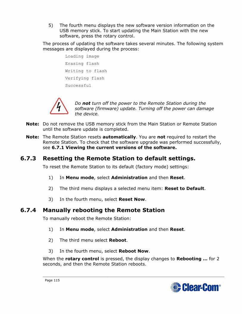
Page 115
5) The fourth menu displays the new software version information on the USB memory stick. To start updating the Main Station with the new
software, press the rotary control.
The process of updating the software takes several minutes. The following system
messages are displayed during the process:
Loading image
Erasing flash
Writing to flash
Verifying flash
Successful
Do not turn off the power to the Remote Station during the software (firmware) update. Turning off the power can damage
the device.
Note: Do not remove the USB memory stick from the Main Station or Remote Station
until the software update is completed.
Note: The Remote Station resets automatically. You are not required to restart the Remote Station. To check that the software upgrade was performed successfully,
see 6.7.1 Viewing the current versions of the software.
6.7.3 Resetting the Remote Station to default settings.
To reset the Remote Station to its default (factory mode) settings:
1) In Menu mode, select Administration and then Reset.
2) The third menu displays a selected menu item: Reset to Default.
3) In the fourth menu, select Reset Now.
6.7.4 Manually rebooting the Remote Station
To manually reboot the Remote Station:
1) In Menu mode, select Administration and then Reset.
2) The third menu select Reboot.
3) In the fourth menu, select Reboot Now.
When the rotary control is pressed, the display changes to Rebooting … for 2
seconds, and then the Remote Station reboots.

Page 116
6.7.5 Saving and restoring the software settings.
To save or restore the software settings:
1) In Menu mode, select Administration and then Settings.
2) To save, in the third menu, select Save. Once you select Save you should not remove the USB stick right away. Depending on the USB stick it might
take up to 5 seconds to complete.
a) In the fourth menu, select either saving to a USB stick or saving locally.
3) To restore, in the third menu, select Restore.
a) In the fourth menu, select either restoring from a USB stick or
restoring from a list of files.
6.8 Diagnostics
The Diagnostics menus help you to monitor the performance of the Remote
Station and diagnose possible system issues.
6.8.1 Viewing powerline information and status
To view line information and status:
1) In Menu mode, select Diagnostics and then Powerlines.
2) From the third menu, select Powerline 1.
3) The fourth menu displays the status and other measures / information for the powerline. The status of the powerline is either Ok [operating
normally], Busy or Error.
For more details of the information displayed, see 22 Menu maps.
Note: Powerline status is also indicated by the powerline LEDS on the
front panel.
Green LED = Ok
Amber LED = Busy
Red LED = Error
For more information about powerline diagnostics, see 25 Troubleshooting.

Page 117
6.8.2 Viewing network information
To view network status information:
1) In Menu mode, select Diagnostics and then Network.
2) To view status information about the powerline:
a) From the third menu, select Powerline.
b) On the fourth menu, the IP address is given.
3) To view status information about the Ethernet:
a) From the third menu, select Ethernet.
b) On the fourth menu, the IP address is given.
6.8.3 Viewing keyset information
To view information about the keysets:
1) In Menu mode, select Diagnostics and then Keysets.
2) From the third menu, select a keyset from 1 to 4.
3) The fourth menu displays the following status information:
• Name – The Channel name
• Talkers – The number of talkers on the Partyline
• Main Stations – The number of Main Stations listening
• Beltpacks – The number of beltpacks listening on the Partyline
• Remote – The number of Remote Stations listening
• Speaker – The number of Speaker Stations listening.
• 2-Wire – The number of 2-wire ports listening
• 4-Wire – The number of 4-wire ports listening
6.9 Setting up a key Expansion Group
See 5.6.4 Setting up a key Expansion Group.
Page 118
7 Using the Main Station/Remote Station
This chapter describes how to use the Main Station/Remote Station, after your HelixNet Partyline system has been installed and configured.
For more information about integrating and using HelixNet Partyline with your
existing intercom infrastructure, see 3 Installing HelixNet Partyline.
Tip: For a quick reference to the functionality of the HMS-4X Main Station, the optional interface modules and the beltpacks, see 2 Panels and Interfaces.
7.1 Using the gooseneck mic, loudspeaker and headset
To use a gooseneck mic to talk to connected intercom users, devices (including
beltpacks) and systems:
1) Connect the gooseneck mic, using the gooseneck mic connector (3-pin female Tuchel connector) on the left of the front panel.
Note: For the location of the gooseneck mic connector, see C
in Table 2-3 Key to
Main Station/Remote Station front panel diagram.
2) To talk to other intercom users and devices:
a) Press the appropriate Talk key
When the mic (gooseneck or headset) is live, the Mic On key is activated automatically.
b) Speak into the mic.
Use the front panel loudspeaker to listen to connected intercom users, devices
and the Program Feed.
To adjust the volume level:
3) Adjust the volume of all incoming audio by turning the loudspeaker rotary
control [Main], located to the left of the loudspeaker.
Adjust the volume of the Program Feed in relation to the overall volume
level by turning the auxiliary loudspeaker rotary control [Prog], located to
the right of the loudspeaker. The Prog volume control is subordinate to
the Main volume control.
To increase the volume level, turn the rotary control(s) clockwise. To decrease the volume level, turn the rotary control(s) counter-clockwise.
Note: When you connect a headset, incoming audio is routed to the
headset instead of the loudspeaker.
Note: You can mute the speaker by pressing the rotary control.

Page 119
As you increase or decrease the volume, the level control LEDs pass
through a range of indicator colors:
LED color Volume level
Green Low
Amber / Green Low / Medium
Amber Medium
Red / Amber Medium / High
Red High
Table 7-1: Loudspeaker volume indicator colors
To use a headset to talk and listen to connected intercom users, devices and
systems:
1) Connect the headset, using the headset connector (4-pin XLR–M) on the far left of the front panel.
The Headset key is automatically activated. Incoming audio is routed to
the headset instead of the loudspeaker.
Note: For the location of the headset connector and the headset key, see B E in Table 2-3 Key to Main Station/Remote Station front
panel diagram.
To configure audio settings for the headset, see 5.2.1 Audio settings for
the headset.
2) To talk to other intercom users and devices:
a) Press the appropriate Talk key.
When the microphone (gooseneck or headset) is live, the Mic On key is
activated automatically.
b) Speak into the microphone.
3) To adjust the volume level of incoming audio to the headset:
a) Adjust the volume of all incoming audio by turning the loudspeaker rotary control [Main]. The control is located to the left of the
loudspeaker.
b) Adjust the volume of the Program Feed in relation to the overall
volume level by turning the auxiliary loudspeaker rotary control
[Prog. The control is located to the right of the loudspeaker.
The Prog volume control is subordinate to the Main volume control.

Page 120
7.1.1 Switching between the headset mic and the gooseneck
mic
When both a Headset microphone and a gooseneck microphone are connected,
press the
Headset key to activate the headset mic.
Press the Headset key again to switch to the gooseneck mic (and deactivate the
headset mic).
Tip: To find out more about Clear-Com accessories, including headsets and gooseneck microphones, see http://www.clearcom.com/product/accessories.
7.2 Entering and exiting Menu mode
Use Menu mode to:
• Configure the settings for the Main/Remote Station, including Channel
and audio settings.
• Administrate the system, monitor system performance and diagnose
system issues.
• Perform software updates.
In Menu mode, the display screens display the four levels of menu. The menu
hierarchy proceeds left to right:
• The top level menu is presented in the first screen (furthest left on the front panel).
• The lowest level menu is presented in the fourth screen (furthest right
on the front panel).
To place the Main/Remote Station in Menu mode, press the Menu key to the left
of the first (left) display screen. To exit Menu mode, do either of the following:
• Press the Menu key again.
• Wait until Menu mode times out. If you fail to press any key on the front
panel for 20 seconds, the display screens revert to showing the standard
Channel information, see Table 2-5 Main Station/Remote Station
display icons and indicators.
7.3 Using the Channel keysets
A keyset (set of controls) is located next to each of the four display screens. In
operating mode, each keyset is dedicated to the control of one of the four assigned intercom Channels. For details of the standard on screen information for
each Channel, see Table 2-5 Main Station/Remote Station display icons and
indicators.
Note: To change (edit) the Channel label (name), see 5.4.1 Editing the Channel
label.

Page 121
The display screens enters screensaver mode (if enabled) if the Main/Remote
Station remains inactive for 10 minutes. Press any key to leave screensaver
mode.
To send a call signal to all the connected devices on that Channel, press the Call
key.
To talk to the all the devices on that Channel:
1) Press the Talk key. When the gooseneck or headset mic is live, the Mic On key is activated automatically.
2) Speak into the headset or gooseneck mic (see also 7.1 Using the gooseneck mic, loudspeaker and headset ).
To adjust the volume of incoming audio per channel, turn the rotary control.
Turn the rotary control clockwise to increase the volume, and counter-clockwise
to decrease volume. The current volume level is shown on screen.
To mute incoming audio per channel, press the rotary control. The display screen displays the muted volume bar.
To unmute incoming audio (restoring the audio to its previous volume level),
press the rotary control again.
Note: In Menu mode, the rotary control for each Channel keyset is used to scroll and
select menu items. For more information, see 5.1 Using the Menus.
7.4 Using the All Talk key
To talk to all connected intercom users, devices and systems, excluding the SA
(Stage Announce) facility:
1) Press the All Talk key to the right of the fourth (last) display screen.
Talk keys for all Channels are activated automatically.
When the mic (gooseneck or headset) is live, the Mic On key is also
activated automatically.
2) Speak into the headset or gooseneck mic (see also 7.1 Using the gooseneck mic, loudspeaker and headset ).
Note: All Channels will enable you to talk to 12 (or 24, according to license) Channels.
Visible Channels will enable you to talk to the four visible Channels.
7.5 Using the SA [Stage Announce] key
Use the SA [Stage Announce] key to speak to an attached SA or Public Address
system (sometimes simply a loudspeaker within the studio, theater or event
area).To make a studio / public announcement:

Page 122
1) Press the SA key to the right of the fourth (last) display screen.
When the mic (gooseneck or headset) is live, the Mic On key is also
activated automatically.
2) Speak into the headset or gooseneck mic (see also 7.1 Using the gooseneck mic, loudspeaker and headset ).
7.6 Using the RMK [Remote Mic Kill] key
Note: The RMK key is only present on the HelixNet Main Station. The Remote Station
has instead an OPT key which is non-functional.
Use the RMK [Remote Mic Kill] key to:
• Send a message to all connected HelixNet Partyline devices to deselect any latched (active) Talk keys.
• Turn off any latched Talk keys on connected analog Partyline beltpacks
and stations.
Note: The OPT key can be used in HelixNet 3.0 and above. The Remote Station must
have a Role selected to use this function. To enable the key, navigate to the Roles page in the CCM, the browser-based configuration tool served by your
device.
To enable the OPT (RMK) key on a Remote Station:
1) Input the IP address of your device into the URL field on a browser. The IP address is found in the 4th screen on the front of your device: MENU >
Networking > Preferences > IP address.
Default Username and Password for the CCM: admin, admin.
2) This takes you to the Overview page in the Core Configuration Manager (CCM). Navigate to Roles > Remote Station > Role > Station > OPT
(RMK) Key in the CCM and select the option by clicking on it.

Page 123
3) Select required option: All Channels to activate RMK on 12 or 24 Channels, Visible Channels to activate RMK on the Channels visible on
your device only, or Disabled (default setting).
Enabling this option in the CCM takes effect immediately on your system,
provided the Role is selected on your device. For more information on Roles see
13 Roles.
Note: All Channels will turn off Talk keys on 12 (or 24 according to license) Channels. Visible Channels will turn of Talk keys on the four Channels you can see on the
front of the device.

Page 124
7.7 Line 1 and 2 LEDs
Note: This section only applies to the HelixNet Main Station.
The beltpacks, Remote Stations and Speaker Stations are connected by one of the
two lines to the Main Station.
The color of the Line 1 and Line 2 LEDs to the left of the front panel
loudspeaker indicate the service status of each powerline:
• Green LED = Ok.
• Amber LED = Busy.
• Red LED = Error.
For more information:
• About the service status of Lines 1 and 2, see 5.9.3 Viewing powerline
information and status.
• About monitoring system performance and diagnosing system issues on
the Main Station, see 5.9 Diagnostics.
7.8 Line and LAN LEDs
Note: This section only applies to the HelixNet Remote Station and Speaker Station.
The Remote Station has a line LED that indicates the status of a powerline
connection to the Main Station. The LAN LED indicates the status of the Ethernet
connection, if present.
The color of the Line and LAN LEDs to the left of the front panel loudspeaker indicate the service status:
• Green LED = Ok.
• Amber LED = Busy.
• Red LED = Error.
Page 125
8 Configuring and managing the Speaker
Station from front menus
This chapter describes how to configure the settings and manage the Speaker
Station using Menu mode. It also shows you how to monitor and diagnose
performance issues, using the Diagnostics menus.
Tip: For a quick reference to the Speaker Station menus, see 22 Menu maps.
For general information about using the menus and configuring settings, see 5.1
Using the Menus.
There is a next and a back activated by pressing the rotary encoders (right one for next, left one for back). There are two levels of the menu, one on the left
screen and one on the right. Next and back shifts the menu by one level down or
up.
8.1 Using the Menus
To place the Speaker Station in Menu mode, press the Menu key. The Speaker
Station menus appear in the display screens.
Note: The Speaker Station menu comes up in the Roles menu by default.
Note: If Menu mode is locked, you must unlock the menus from CCM before you can enter the menu. See 5.7 Administration.
8.1.1 Configuring settings
To configure settings:
1) For each menu, turn the rotary control to scroll the menu items. Turn the rotary control:
• Counter-clockwise to scroll up the menu items.
• Clockwise to scroll down the menu items.
To return to the previous level of menu, press the left-hand rotary key.
To go to the next level of menu, press the right-hand rotary key.
Selected menu items are highlighted in solid yellow.
2) When you have selected a setting, press the right-hand rotary key to enable the setting on the Speaker Station.
8.1.2 Exiting Menu mode
To exit Menu mode do either of the following:
• Press the Menu key.
Page 126
• Wait until Menu mode times out. If you fail to press any key on the
Speaker Station for 20 seconds, the display screen reverts to showing
the standard Channel information.
8.2 Configuring the Audio settings
8.2.1 Audio settings for the headset
To configure the audio settings for the headset, see 5.2.1 Audio settings for
the headset.
8.2.2 Audio settings for the microphone
To configure the audio settings for the microphone, see 5.2.2 Audio settings for
the microphone.
8.2.3 Audio settings for the Front Panel
To configure the audio settings for the front panel, see 5.2.7 Audio settings for
the Front Panel.
8.3 Station Settings
8.3.1 Setting Keyset Assignments
To configure the Keyset Assignments settings, see 5.3.2 Setting Keyset
Assignments.
8.3.2 Setting key latching
To configure key latching, see 5.3.3 Setting key latching.
You can also configure key latching so that the Talk keys automatically unlatch
whenever the Shift key is pressed. To do so:
1) In Menu mode, select Station Settings and then Keysets.
2) From the third menu, select Unlatch on Shift.
3) From the fourth menu select:
• Enabled (default)
• Disabled
8.3.3 Setting display screen brightness
To configure display screen brightness, see 5.3.7 Setting display screen
brightness.

Page 127
8.3.4 Setting key brightness
To configure key brightness, see 5.3.8 Setting key brightness.
8.3.5 Setting the screensaver
To configure the screensaver, see 5.3.9 Setting the screensaver.
8.4 Connecting the Speaker Station to a Main Station
To connect the Speaker Station to a Main Station, see 6.5 Connecting the Remote Station to a Main Station using .
8.5 Networking
In Menu mode > Networking, you can:
• See networking settings including DHCP, IP address, subnet mask and
gateway.
• Pair to a Main Station.
8.5.1 Viewing network preferences
To view network preferences:
1) In Menu mode, select Networking > Preferences
You can view the following:
• DHCP enabled or disabled
• IP address
• Subnet Mask
• Gateway
8.5.2 Pairing to a Main Station
To pair to a Main Station:
2) In Menu mode, select Networking > Pair to Station.
3) Select By Name or By IP Address.
8.6 Administration
8.6.1 Viewing the current versions of the software
To view the current version of the software, see 6.7.1 Viewing the current
versions of the software.
Page 128
8.6.2 Updating the software
To update the software, see 6.7.2 Updating the software.
Note: You can only update the Speaker Station software from the Main Station.
8.6.3 Resetting the Speaker Station to default (factory mode)
settings.
To reset the Speaker Station to its default (factory mode) settings see:
1) In Menu mode, select Administration and then Reset.
2) The third menu displays a selected menu item: Reset to Default.
3) In the fourth menu, select Reset Now.
8.6.4 Manually rebooting the Speaker Station
To manually reboot the Speaker Station:
1) In Menu mode, select Administration and then Reset.
2) The third menu select Reboot.
3) In the fourth menu, select Reboot Now.
When the rotary control is pressed, the display changes to Rebooting … for 2
seconds, and then the Speaker Station reboots.
8.7 Diagnostics
8.7.1 Viewing network information
To view network information, see 6.8.2 Viewing network information.
8.7.2 Viewing keysets information
To view key sets information, see 6.8.3 Viewing keyset information.
Page 129
9 Using the Speaker Station
This chapter describes how to use the Speaker Station, after your HelixNet Partyline system has been installed and configured.
For more information about integrating and using HelixNet Partyline with your
existing intercom infrastructure, see 3 Installing HelixNet Partyline.
9.1 Using the gooseneck mic, loudspeaker and headset
To use a gooseneck mic to talk to connected intercom users, devices (including
beltpacks) and systems:
1) Connect the gooseneck mic, using the gooseneck mic connector (3-pin female Tuchel connector) on the left of the front panel.
Note: For the location of the gooseneck mic connector, see Table 2-24 Key to
Speaker Station front panel
2) To talk to other intercom users and devices:
a) Press the Talk key.
When the mic (gooseneck or headset) is live, the Mic key is activated automatically.
b) Speak into the microphone.
Use the front panel loudspeaker to listen to connected intercom users, devices
and the Program Feed.
To adjust the volume level:
3) Adjust the volume of all incoming audio by turning the loudspeaker rotary
control [Main], located in the center of the panel.
To increase the volume level, turn the rotary control(s) clockwise. To
decrease the volume level, turn the rotary control(s) counter-clockwise.
Note: When you connect a headset, incoming audio is routed to the
headset instead of the loudspeaker.
Note: You can mute the speaker by pressing the rotary control.
As you increase or decrease the volume, the level control LED passes
through a range of indicator colors.
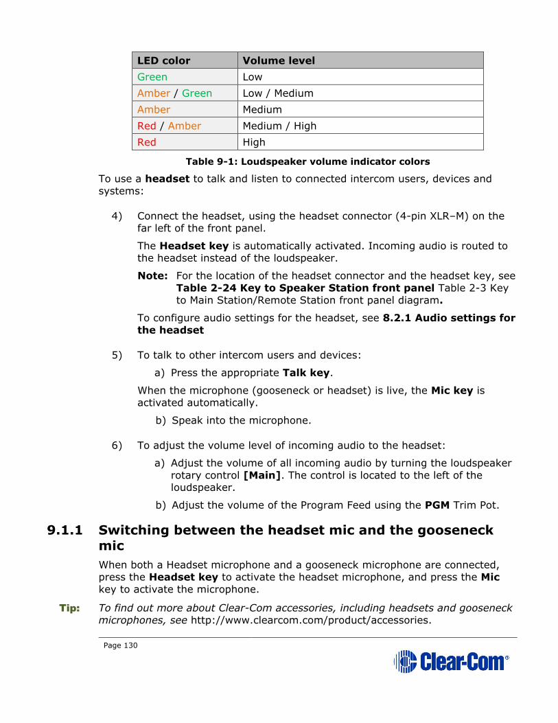
Page 130
LED color Volume level
Green Low
Amber / Green Low / Medium
Amber Medium
Red / Amber Medium / High
Red High
Table 9-1: Loudspeaker volume indicator colors
To use a headset to talk and listen to connected intercom users, devices and
systems:
4) Connect the headset, using the headset connector (4-pin XLR–M) on the far left of the front panel.
The Headset key is automatically activated. Incoming audio is routed to the headset instead of the loudspeaker.
Note: For the location of the headset connector and the headset key, see
Table 2-24 Key to Speaker Station front panel Table 2-3 Key
to Main Station/Remote Station front panel diagram.
To configure audio settings for the headset, see 8.2.1 Audio settings for
the headset
5) To talk to other intercom users and devices:
a) Press the appropriate Talk key.
When the microphone (gooseneck or headset) is live, the Mic key is
activated automatically.
b) Speak into the microphone.
6) To adjust the volume level of incoming audio to the headset:
a) Adjust the volume of all incoming audio by turning the loudspeaker
rotary control [Main]. The control is located to the left of the loudspeaker.
b) Adjust the volume of the Program Feed using the PGM Trim Pot.
9.1.1 Switching between the headset mic and the gooseneck
mic
When both a Headset microphone and a gooseneck microphone are connected,
press the Headset key to activate the headset microphone, and press the Mic
key to activate the microphone.
Tip: To find out more about Clear-Com accessories, including headsets and gooseneck microphones, see http://www.clearcom.com/product/accessories.
Page 131
9.2 Entering and exiting Menu mode
Use Menu mode to:
• Configure the settings for the Speaker Station, including Channel and
audio settings.
• Administrate the system, monitor system performance and diagnose
system issues.
In Menu mode, the display screens show two out of four levels of menu. The
menu hierarchy proceeds left to right:
• The top level menu is presented in the first screen (left on the front
panel).
• The second level menu is presented in the second screen (right on the
front panel).
Note: Press the right-hand rotary control to shift to the next menu level.
To place the Speaker Station in Menu mode, press the Menu key to the left of
the first (left) display screen. To exit Menu mode, do either of the following:
• Press the Menu key again.
• Wait until Menu mode times out. If you fail to press any key on the front panel for 20 seconds, the display screens revert to showing the standard
Channel information:
• Channel label (name).
• Listen (volume) level.
Tip: For more detailed information about using the Speaker Station menus, see 5 Configuring and managing the Main Station from device menus.
This chapter describes how to use the Speaker Station, after your HelixNet
Partyline system has been installed and configured.
For more information about integrating and using HelixNet Partyline with your
existing intercom infrastructure, see 3 Installing HelixNet Partyline.
Tip: For a quick reference to the functionality of the Speaker Station, the optional interface modules and the beltpacks, see 2 Panels and Interfaces.
9.3 Using the Channel keysets
A keyset (set of controls) is located next to each of the two display screens. In
operating mode, each keyset is dedicated to the control of one of the four
assigned intercom Channels. You can also use the shift key to switch to the other
channels configured on keysets 3-4. For details of the standard on screen
information for each Channel, see Table 2-5 Main Station/Remote Station
display icons and indicators.
Page 132
Note: To change (edit) the Channel label (name), see 3.4.1 Editing the Channel
label.
The display screens enters screensaver mode (if enabled) if the Main Station
remains inactive for 10 minutes. Press any key to leave screensaver mode.
To send a call signal to all the connected devices on that Channel, press the Call key.
To talk to the all the devices on that Channel:
1) Press the Talk key. When the gooseneck or headset mic is live, the Mic On key is activated automatically.
2) Speak into the headset or gooseneck mic (see also 5.1 Using the gooseneck mic, loudspeaker and headset ).
To adjust the volume of incoming audio, turn the rotary control. Turn the
rotary control clockwise to increase the volume, and counter-clockwise to
decrease volume. The current volume level is shown on screen.
To mute incoming audio, press the rotary control. The display screen displays
the muted volume bar.
To unmute incoming audio (restoring the audio to its previous volume level),
press the rotary control again.
Note: In Menu mode, the rotary control for each Channel keyset is used to scroll and select menu items. For more information, see 5.1 Using the Menus.
9.4 Line and LAN LEDs
The Speaker Station has a line LED that indicates the status of a powerline connection to the Main Station. The LAN LED indicates the status of the Ethernet
connection, if present.
The color of the Line and LAN LEDs to the left of the front panel loudspeaker
indicate the service status:
• Green LED = Ok.
• Amber LED = Busy.
• Red LED = Error.

Page 133
10 Configuring and managing the beltpacks
from front menus
This chapter describes how to configure the settings and manage the beltpacks
using Menu mode. It also shows you how to monitor and diagnose performance
issues, using the Diagnostics menus.
Tip: For a quick reference to the Main Station menus, see 22 Menu maps.
10.1 Using the Menus
To place the beltpack in Menu mode, press the Menu key on the top of the
beltpack.
Note: The Beltpack menu shows the Roles menu by default.
Note: If Menu mode is locked on the beltpack, you must unlock the menus from CCM
before you can enter the menu. See 5.7 Administration.
To enter the menu mode from the Roles screen, press the left hand Call button.
10.1.1 Configuring settings
To configure settings:
1) For each menu, turn either of the side-mounted rotary controls to scroll the menu items. Turn the rotary control:
• Counter-clockwise to scroll up the menu items.
• Clockwise to scroll down the menu items.
Off-screen menu items are indicated with arrows at the top and / or
bottom of the display screen.
Back (with an arrow pointing left) indicates a previous level of menu.
To return to the previous level of menu, press the left-hand Call key.
An arrow pointing right indicates another level of menu under that menu
item.
To go to the next level of menu, press the right-hand Call key.
Selected menu items are highlighted in solid yellow.
2) The final level of menu (the second or third display screen) displays the settings that relate to your previous menu choices (system features or
functionality).
The current setting is indicated by a dotted box around the menu item
When you have selected a setting, press the right-hand Call key to
enable the setting on the Main Station.

Page 134
10.1.2 Exiting Menu mode
To exit Menu mode on the beltpack, do either of the following:
• Press the Menu key.
• Wait until Menu mode times out. If you fail to press any key on the beltpack for 20 seconds, the display screen reverts to showing the
standard Channel information.
10.2 Configuring the Role settings
To configure the Role settings for the headset
1) In Menu mode press the left-hand Call Key and then select Roles.
2) Select the required Role.
3) To confirm the selected setting, press the right-hand Call key.
4) The beltpack applies the setting and reverts to the standard display screen.
10.2.1 Viewing Hostname
The hostname (the unique name given to any device on a network) of your
beltpack can be seen in the Roles section of the menu.
To view the hostname for your beltpack:
1) In Menu mode press the left-hand Call Key and then select Roles.
2) The device’s hostname can be seen at the top of the list of available Roles.
Note: You cannot change the hostname from this screen. The hostname for beltpacks
must be changed from the browser-based Core configuration Manager (the CCM).
From the Overview page of the CCM, click on any device image to access configuration details for that device’s hostname.
10.3 Configuring the Audio settings
To configure the audio settings for the headset:
1) In Menu mode press the left-hand Call Key and then select Audio
Settings.
2) To adjust sidetone gain on the headset:
a) Select Sidetone Gain.
b) Select one of the following:
Page 135
• 0dB
• - 6dB
• -12dB (default)
• -18dB
c) To confirm the selected setting, press the right-hand Call key.
Go back to the previous menu level by pressing the left-hand Call key.
3) To limit the maximum audio level that can be delivered to the headphones:
a) Select Headphone Limit.
b) Select one of the following:
• Off
• +6dB
• 0dB (default)
• - 6dB
c) To confirm the selected setting, press the right-hand Call key.
Note: When Headphone Limit is set to anything except Off, a LIM
indication will show up at the top right of the display
Go back to the previous menu level by pressing the left-hand Call key.
4) Sidetone tracking means that the sidetone level varies according to the main volume level. To set (or disable) sidetone tracking on the headset:
a) Select Sidetone Control.
b) Select one of the following:
• Tracking (default)
• Non-Tracking
• Disabled
c) To confirm the selected setting, press the right-hand Call key.
Go back to the previous menu level by pressing the left-hand Call key.

Page 136
5) To set the type of mic on the headset:
a) Select HS Mic Type.
b) Select either of the following types of mic.
• Electret (-15 dB)
• Dynamic (0 dB) (default)
• Dynamic (low). This setting corresponds to -10 dB gain on
HBP-2X and -15 dB gain on HXII-BP-X4.
Note: In electret mode, phantom power is provided for an electret mic.
In dynamic mode, no phantom power is provided. Mic input levels
are also adjusted between the different modes to suit the different mic types.
c) To confirm the selected setting, press the right-hand Call key.
10.4 Audio settings for the microphone
To configure the audio settings for the microphone:
1) In Menu mode, select Audio Settings.
Note: The Headroom setting is only available on the HBP-2X Beltpack.
2) To select the Headroom:
a) From the third menu, select Headroom.
b) From the fourth menu, select one of the following:
• Normal (default)
• High
3) To enable or disable the Contour Filter:
a) From the third menu, select Contour Filter
b) From the fourth menu, select one of the following:
• Enabled
• Disabled (default)
10.5 Configuring the beltpack Settings
In Menu mode > Beltpack Settings, you can:
• Assign Channels to the left and right beltpack keysets (set of controls).
• Enable (or disable) Talk key latching.
• Enable (or disable) beltpack vibration when a call signal is received.
Page 137
• Enable (or disable) the USB flasher mode for the beltpack.
Tip: For a quick reference to the keysets on the beltpack, see 2.5.1 HBP-2X user controls (front and side view) or 2.6.1 HXII-BP-X4 Beltpack user controls
(top view).
10.5.1 Assigning Channels
You can assign any two available Channels to the beltpack (including the same Channel to both keysets).
To assign a Channel:
1) In Beltpack Settings select Left Channel or Right Channel.
2) Select one of the available Channels (or none):
3) To confirm the selected setting, press the right-hand Call key.
10.5.2 Setting Talk key latching
To enable (or disable) Talk key latching:
1) In Beltpack Settings select Right Talk Latch or Left Talk Latch
2) Select one of the following:
• Latching (default)
• Non-Latching
• Disabled
Note: The setting applies to both Channels on the beltpack.
3) To confirm the selected setting, press the right-hand Call key.
10.5.3 Setting USB Flasher mode
To enable (or disable) USB Flasher mode
1) In Beltpack Settings select either Left Keyset or Right Keyset
2) Select USB Flasher
3) Select one of the following:
• Disabled (default)
• Blinking
• Solid
Page 138
4) To confirm the selected setting, press the right-hand Call key.
10.5.4 Setting the beltpack to vibrate when called
To enable (or disable) vibration when a Call signal is received:
1) In Beltpack Settings select Vibrate on Call.
2) Select one of the following:
• On
• Off (default)
3) To confirm the selected setting, press the right-hand Call key.
10.6 Configuring the Display Settings
In Menu mode > Display Settings, you can:
• Set the brightness of the display screen.
• Set the brightness of the Talk and Call keys.
• Enable (or disable) the screensaver.
• Rotate the display.
10.6.1 Setting display screen brightness
By default, the display screen is set to medium brightness. To set the brightness of the display screen:
1) In Menu mode, press the left-hand Call Key and then select Display Settings.
2) Select OLED Brightness.
3) Select one of the following:
• High
• Medium (default)
• Low
4) To confirm the selected setting, press the right-hand Call key.
10.6.2 Setting the brightness of the Talk and Call keys
By default, the Talk and Call keys are lit when active (on) and dim when inactive (off) (High / Low).
To set the brightness of the Talk and Call keys:
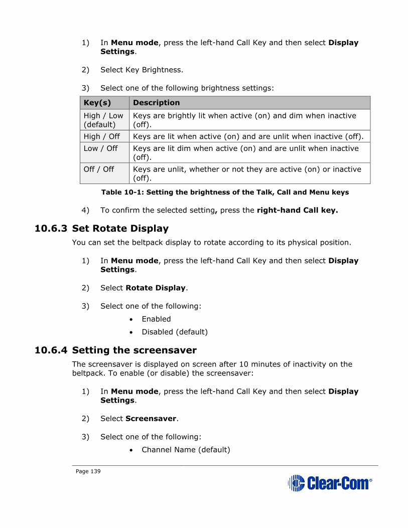
Page 139
1) In Menu mode, press the left-hand Call Key and then select Display Settings.
2) Select Key Brightness.
3) Select one of the following brightness settings:
Key(s) Description
High / Low
(default)
Keys are brightly lit when active (on) and dim when inactive
(off).
High / Off Keys are lit when active (on) and are unlit when inactive (off).
Low / Off Keys are lit dim when active (on) and are unlit when inactive
(off).
Off / Off Keys are unlit, whether or not they are active (on) or inactive
(off).
Table 10-1: Setting the brightness of the Talk, Call and Menu keys
4) To confirm the selected setting, press the right-hand Call key.
10.6.3 Set Rotate Display
You can set the beltpack display to rotate according to its physical position.
1) In Menu mode, press the left-hand Call Key and then select Display Settings.
2) Select Rotate Display.
3) Select one of the following:
• Enabled
• Disabled (default)
10.6.4 Setting the screensaver
The screensaver is displayed on screen after 10 minutes of inactivity on the
beltpack. To enable (or disable) the screensaver:
1) In Menu mode, press the left-hand Call Key and then select Display
Settings.
2) Select Screensaver.
3) Select one of the following:
• Channel Name (default)

Page 140
• Hostname
• Role Name
• Blank
• Disabled
4) To confirm the selected setting, press the right-hand Call key.
10.7 Network - Powerline
Note: This section applies only to the HBP-2X Beltpack and the HXII-BP-X4 when
powered by powerline.
In Menu mode > Network, you can view the IP address of the beltpack:
1) In Menu mode, press the left-hand Call Key and then select Network.
10.8 Network - Ethernet
Note: This section applies only to the HXII-BP-X4 when powered over Ethernet.
In Menu mode > Networking, you can:
• See networking settings including DHCP, IP address, subnet mask and
gateway.
• Pair to a Main Station.
10.8.1 Viewing network preferences
To view network preferences:
1) In Menu mode, select Networking > Preferences
You can view the following:
• DHCP enabled or disabled
• IP address
• Subnet Mask
• Gateway
10.8.2 Pairing to a Main Station
To pair to a Main Station:
2) In Menu mode, select Networking > Pair to Station.
Select By Name or By IP Address.

Page 141
10.9 Administration
In Menu mode > Administration, you can:
• View the current version of the software on the beltpack.
• Reset the beltpack to default (factory mode) settings.
The beltpacks receive updated (default) Channel label information. Other local
beltpack settings will not be reset if the Main Station is reset to default settings.
10.9.1 To view the current version of the software on the
beltpack:
1) In Menu mode, press the left-hand Call Key and then select Administration.
2) Select Software Version.
3) The current version of the software is displayed. The software version information will appear similar to the following example:
npl-x.x.xx.xxxx, uboot
Where x is a numerical value.
10.9.2 Resetting the beltpack to default (factory mode) settings
To reset the beltpack to default (factory mode) settings:
1) In Menu mode, press the left-hand Call Key and then select Administration.
2) Select Reset to Default.
3) Reset Now is displayed (shown as selected). To reset the beltpack, press the right-hand Call key.
Note: Resetting the beltpack to default (factory mode) settings will delete any IP settings, and remove the pairing with the Main Station.
10.10 Diagnostics
The Diagnostics menus help you to monitor the performance of the beltpack and diagnose possible system issues.
10.10.1 Viewing information about the hardware (main PCB) on
the beltpack
To view information about the Part, Revision and Serial number of the main
PCB on the beltpack:

Page 142
1) In Menu mode, press the left-hand Call Key and then select Diagnostics.
2) Select Hardware > Main PCB.
The Part, Revision and Serial number for the PCB are displayed. The
format is similar to the following:
Part xxxxxxx
Revision: x
Serial: x
Where x is a numerical value.
10.10.2 Viewing powerline information and status
To view powerline information and status:
1) In Menu mode, press the left-hand Call Key and then select Diagnostics.
2) Select Powerline.
The status and other powerline information are displayed. For more
information, see 22 Menu maps.
Page 143
11 Using the HBP-2X Beltpack
This chapter describes how to use the HBP-2X Beltpack, after your HelixNet Partyline system has been installed and configured.
For more information about integrating and using HelixNet Partyline with your
existing intercom infrastructure, see 19 Connecting to Other Intercom
Systems.
Tip: For a quick reference to the functionality of the HBP-2X Beltpack, the HMS-4X Main Station, and the optional interface modules, see 2 Panels and Interfaces.
11.1 Using the beltpack keysets
The HBP-2X Beltpack supports two Partyline Channels, with a separate keyset (set
of controls) dedicated to the control of each Channel:
• The left-hand keyset controls the first (top) Channel displayed on
screen.
• The right-hand keyset controls the second (bottom) Channel displayed
on screen.
For details of the standard on screen information for each Channel, see Table 2-5
Main Station/Remote Station display icons and indicators.
Note: For more information about using the beltpack in Menu mode, see 10 Configuring and managing the beltpack.
The display screens enter screensaver mode (if enabled) if the beltpack remains
inactive for a period of time. Press any key to exit screensaver mode.
To send a call signal to all the connected devices (beltpacks and Main Station)
on that Channel, press the Call key.
To talk to all the devices connected to the Channel:
1) Connect a headset, using the 4-pin XLR–M connector on the base / rear of the beltpack.
Note: For the location of the headset connector and the headset
key, see E in Table 2-34: Key to HBP-2X Beltpack
connectors and controls (base view).
2) Press the Talk key.
3) Speak into the headset mic.
To adjust the volume of incoming audio for a Channel, turn the appropriate side-
mounted rotary control.
Turn the rotary control clockwise to increase the volume, and counter-clockwise
to decrease volume. The current volume level for the Channel is shown on screen.
Page 144
11.2 Entering and exiting Menu mode
Use Menu mode to:
• Configure the settings for the Beltpack, including Channel and audio
settings.
• Monitor beltpack performance and diagnose issues.
To enter Menu mode, press the Menu key. To exit Menu mode, press the Menu key again.
For more information about using Menu mode on the beltpack, see 10
Configuring and managing the beltpack. For information on changing the
beltpack IP address, see 4.3.3 Change the IP address of a HelixNet device
from the device front menu screens.
11.3 Adjusting the Program Feed volume level.
To adjust the listen level (volume) of the Program Feed to the beltpack, turn the
rear / base rotary control.
Turn upwards to increase the listen level (volume), and downwards to decrease the listen level (volume).
While the listen level is adjusted, the listen level for the Program Feed replaces
the standard Channel information on screen.
The Main Station is used to assign the Program Feed to Channels. For more
information, see 5.4.2 Assigning the Program Listen to a Channel.

Page 145
12 Using the HXII-BP-X4 Beltpack
This chapter describes how to use the HXII-BP-X4 Beltpack, after your HelixNet Partyline system has been installed and configured.
For more information about integrating and using HelixNet Partyline with your
existing intercom infrastructure, see 19 Connecting to Other Intercom
Systems.
Tip: For a quick reference to the functionality of the HXII-BP-X4 Beltpack, the HMS-4X Main Station, and the optional interface modules, see 2 Panels and Interfaces.
12.1 Using the beltpack keysets
The HXII-BP-X4 Beltpack supports two Partyline Channels, with a separate keyset
(set of controls) dedicated to the control of each Channel:
• The left-hand keyset controls the first (top) Channel displayed on
screen.
• The right-hand keyset controls the second (bottom) Channel displayed
on screen.
For details of the standard on screen information for each Channel, see Table 2-5
Main Station/Remote Station display icons and indicators.
Note: For more information about using the beltpack in Menu mode, see 10 Configuring and managing the beltpacks from device menus.
The display screens enter screensaver mode (if enabled) if the beltpack remains
inactive for a period of time. Press any key to exit screensaver mode.
To send a call signal to all the connected devices (beltpacks and Main Station)
on that Channel, press the Call key.
To talk to all the devices connected to the Channel:
1) Connect a headset, using the 4-pin XLR–M connector on the base / rear of the beltpack.
Note: For the location of the headset connector and the headset
key, see D in Table 2-41 Key to HXII-BP-X4 (base
view).
2) Press the Talk key.
3) Speak into the headset mic.
To adjust the volume of incoming audio for a Channel, turn the appropriate side-
mounted rotary control.
Turn the rotary control clockwise to increase the volume, and counter-clockwise
to decrease volume. The current volume level for the Channel is shown on screen.

Page 146
12.2 Entering and exiting Menu mode
Use Menu mode to:
• Configure the settings for the Beltpack, including Channel and audio
settings.
• Monitor beltpack performance and diagnose issues.
To enter Menu mode, press the Menu key. To exit Menu mode, press the Menu key again.
For more information about using Menu mode on the beltpack, see 10
Configuring and managing the beltpacks from device menus.
For information on changing the beltpack IP address, see 4.3.3 Change the IP
address of a HelixNet device from the device front menu screens.
12.3 Adjusting the Program Feed volume level.
To adjust the listen level (volume) of the Program Feed to the beltpack, use the
up and down controls on the front of the beltpack. See 2.6.2 HXII-BP-X4
Beltpack connectors and controls (front view).
Use the up arrow control to increase the listen level (volume), and use the down
arrow control to decrease the listen level (volume).
While the listen level is adjusted, the listen level for the Program Feed replaces
the standard Channel information on screen.
The Main Station is used to assign the Program Feed to Channels. For more information, see 5.4.2 Assigning the Program Listen to a Channel.
12.4 Binaural audio
The HXII-BP-X4 beltpack with 5-pin headset connector has a binaural audio adjustment for the left and right earphone. This means that you can separately
adjust the audio volume level in the left and right earphone. To adjust the left or
right hand earphone volume:
1) Press the OPT button on the beltpack.
2) Use the left and right rotary controllers to balance the volume of the left and right channels respectively. Turn the rotary control clockwise to
balance the volume to the right ear, and counter-clockwise to balance the
volume to the left ear. The current balance level for each Channel is
shown on screen.

Page 147
13 Roles
13.1 Roles overview
A Role is a pre-set configuration that includes Channel assignment, audio settings,
IFBs, relays etc. Each HelixNet device has a default Role that can be used as it is
or modified to fit requirements. Each Role can be given a name (a label) that corresponds to a common user workflow, such as producer, director, A1, etc.
When adding new Roles, you will modify an existing template, using either the
default Role for that device, or another Role that you have already made. Default
Roles can be modified but not deleted or loaded to devices, you will always work
with a copy. Default Roles can be returned to factory settings if required.
To use Roles, you must have HelixNet 3.0 or above installed on your Main Stations.
Roles are created and edited in the Core Configuration Manager (CCM) and are a
feature of HelixNet 3.0 and above. Once created in the Roles page, a Role will be
available for selection from any device which is connected to your HelixNet
system. Roles can be configured for:
• Main Stations
• Remote Stations
• Speaker Stations
• Beltpacks.
Roles can be created, cloned, edited and deleted in the Roles page.
Each device has a set of configuration options relevant to that unit. Configurable
details include keysets, audio settings, program feeds and relays.
Note: A Role can be selected by many devices.
Roles can be created in the CCM at any time, but to use the Roles, devices must
be connected to your system (for more information, see 17 Linking Main Stations and 18 Linking Remote Stations and Speaker Stations).
To create and use Roles
1) Open the CCM by typing the Main Station’s IP into the URL field of a browser (Default username and password: admin, admin).
2) Go to the Roles page in the CCM by clicking on the Roles button in the top navigation bar.
3) Add or clone a Role or Roles.
4) Configure Role parameters (you can use editable default settings).
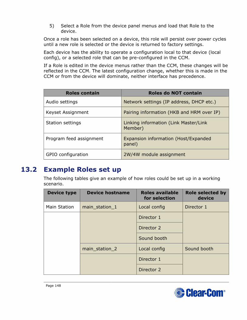
Page 148
5) Select a Role from the device panel menus and load that Role to the device.
Once a role has been selected on a device, this role will persist over power cycles
until a new role is selected or the device is returned to factory settings.
Each device has the ability to operate a configuration local to that device (local config), or a selected role that can be pre-configured in the CCM.
If a Role is edited in the device menus rather than the CCM, these changes will be
reflected in the CCM. The latest configuration change, whether this is made in the
CCM or from the device will dominate, neither interface has precedence.
Roles contain Roles do NOT contain
Audio settings Network settings (IP address, DHCP etc.)
Keyset Assignment Pairing information (HKB and HRM over IP)
Station settings Linking information (Link Master/Link
Member)
Program feed assignment Expansion information (Host/Expanded
panel)
GPIO configuration 2W/4W module assignment
13.2 Example Roles set up
The following tables give an example of how roles could be set up in a working
scenario.
Device type Device hostname Roles available
for selection
Role selected by
device
Main Station main_station_1 Local config Director 1
Director 1
Director 2
Sound booth
main_station_2 Local config Sound booth
Director 1
Director 2

Page 149
Sound booth
Device type Device
hostname
Roles available
for selection
Role selected by
device
Remote Station remote_station_1 Local config Green room
Green room
Device type Device
hostname
Roles available
for selection
Role selected by
device
Speaker Station speaker_station_1 Local config Local config
None configured
Device type Device
hostname
Roles available
for selection
Role selected by
device
Belt pack HBP-2X xxxxxxxxx
Local config Lighting 1
Lighting 1
Lighting 2
Sound 1
Sound 2
HXII-BP-X4
xxxxxxxxx
Local config Lighting 1
Lighting 1
Lighting 2
Sound 1
Sound 2

Page 150
Figure 13-1 Example of Roles in use in the Assignments page of the CCM
Note: A Role can be selected by many devices.
For more detail on setting up Roles see 15 Using the CCM to configure Role.
Note: Program input feeds are an exception in this screen, they will always be associated with a device rather than a Role.
The Roles view button
Live Roles are visible in the Assignments page

Page 151
13.3 Device default Roles
Each device type has a default configuration which can be edited and/or cloned,
but not deleted. When creating new Roles you will always use an existing Role as
a template. The default Role is editable, so you can create Roles based on a
default Role edited to reflect your system requirements.
If you edit the default Role of any device, this configuration will persist until the
device is returned to factory settings in the General > Maintenance page of the
CCM.
13.4 To select a Role for a device
Select a role for a device from the display panels on that device. Go to Menu >
Station Settings > Preferences > Roles to select a role.
1) On the device, press the MENU button to enter menu mode.
2) For each menu, turn the rotary control clockwise to scroll down the menu items. Turn counter clockwise to scroll up the menu items.
Off-screen menu items are indicated by arrows at the top and/or bottom
of the screen.
Selected menu items (which create your path through the four menus) are highlighted in solid yellow.
The current setting is indicated by a dotted box around the menu item
3) When you have selected a setting by rotating the right hand rotary control, press that rotary control to enable the setting on the Main
Station.
Beltpacks will display a Role selection screen when first powered up. Simply select the required Role.
For more information, see 5.1 Using the Menus.
13.5 Creating and editing Roles in the CCM
• Use the ADD button to create a new role with a new label based on a
default template. This is the easiest way to create roles quickly with
different labels, for example Camera, Sound, Production and so on.
• Use the CLONE button to copy an existing Role. This is the easiest way
to create copies of Roles with the same label (appended by one), for
example Camera1, Camera2, Camera3 and so on.
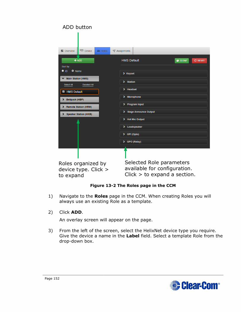
Page 152
Figure 13-2 The Roles page in the CCM
1) Navigate to the Roles page in the CCM. When creating Roles you will always use an existing Role as a template.
2) Click ADD.
An overlay screen will appear on the page.
3) From the left of the screen, select the HelixNet device type you require. Give the device a name in the Label field. Select a template Role from the
drop-down box.
Selected Role parameters available for configuration. Click > to expand a section.
ADD button
Roles organized by device type. Click > to expand

Page 153
Figure 8-2 Add Role Dialog
4) Click Add. This creates a new role which you will see on the left side of the page under device type.
5) To edit a Role, click on it on the left side of the page so it has an orange highlight. Then access configuration parameters on the center right of the
page.
Note: Roles can be deleted in this page. You cannot delete the default Role.
Select device type from here
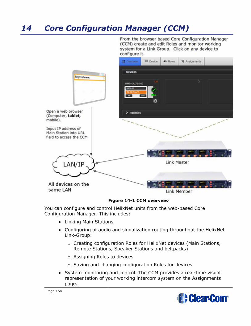
Page 154
14 Core Configuration Manager (CCM)
Figure 14-1 CCM overview
You can configure and control HelixNet units from the web-based Core Configuration Manager. This includes:
• Linking Main Stations
• Configuring of audio and signalization routing throughout the HelixNet
Link-Group:
o Creating configuration Roles for HelixNet devices (Main Stations,
Remote Stations, Speaker Stations and beltpacks)
o Assigning Roles to devices
o Saving and changing configuration Roles for devices
• System monitoring and control. The CCM provides a real-time visual
representation of your working intercom system on the Assignments
page.

Page 155
• Access to device control menus can be restricted from the CCM.
• Upgrading units.
Note: You can also configure and control HelixNet units using the front panel menu
interfaces on each unit. See:
• 5 Configuring and managing the Main Station from device menus
• 6 Configuring and managing the Remote Station from device
menus
• 8 Configuring and managing the Speaker Station from device
menus
• 10 Configuring and managing the beltpacks from device menus
• 11 Using the HBP-2X Beltpack
• 12 Using the HXII-BP-X4 Beltpack.
Note: Some functionality (for example, creating Roles) is only available from the CCM.
14.1 Access the CCM
To access the Core Configuration Manager, enter the IP address of the HelixNet
Main Station, as displayed on the front panel, into the URL field of your browser.
If the unit is reachable over your network, this will take you to the Overview
page of the CCM that is served by the unit.
Note: Default username and password for the CCM: admin, admin.
14.2 Minimum requirements for the CCM
The CCM is supported on the latest versions of all major web browsers including
Google Chrome, Safari, Firefox, Internet Explorer.
Note: Any IP connectivity in HelixNet requires an Ethernet module in the Main
Station.

Page 156
14.3 Overview page
Figure 14-2 Overview page
Note: There is a navigation bar at the top of the page: Overview, Device, Roles
Assignments and Accounts.
As HelixNet Main Stations are added to the group, they appear in this screen. To
access the configuration and control options for any one of the units in the group,
click on the device within the Overview page. Linked units can be configured
either from the host device, or by proxy from this screen.
In this page, Devices, in the upper part of the screen represents the linked Main
Stations. Endpoints, in the lower part of the screen, are the devices which are
paired or powerlined to the Main Stations. For example, these could be Remote
Stations, Speaker Stations and Beltpacks. In this screen, clicking on a Main
Station image will offer comprehensive configuration options. Clicking on an Endpoint allows you to change its name or Role and to reboot or reset to default.
There is also a troubleshooting option. Click on device images to explore
configuration options available for different devices on this page.

Page 157
Note: The Home button takes you to the General page of the Main Station your
browser is connected to (the host device) which has an orange highlight.
Main Station device image shows:
Hostname
Model
IP address (orange highlight if this is
the device your browser is pointing to,
the host device)
Modules installed on Main Station
14.4 Device page
From the Device page of a Main Station, you can access general functions relating
to the device your browser is pointing to (the host device) and also link devices.
There are four buttons in the left margin, below the device image; General,
Linking, Network and Ports. Click on a button to access a configuration page.
Figure 14-3 Device page
Click + to expand
Device configuration pages
Select to change device name
Endpoint device image shows:
Hostname
Selected Role
Model
Main Station the device is
connected to.
Page 158
14.5 General Page
14.5.1 Changing a device hostname from the Device page
To change a device name, click on the existing name and enter a new one. Either
press the <ENTER> key or click the blue check mark to apply changes.
When using hostnames, it is advisable to follow the usual conventions for giving labels to devices used in electronic communication. For instance; do not use
spaces, do not rely on case sensitivity, and make the name meaningful in a way
appropriate to the context. This field can be up to 14 characters.
14.5.2 License
Your HelixNet Main Station arrives with a license for 12 Channels. To increase
capacity to 24 Channels, please contact your Clear-Com dealer. You will need to
provide your system ID, listed in this section of the CCM. When you receive a
license code from them, input it here to increase available Channels. Each linked
device must be licensed from the home page of the host device, units cannot be licensed by proxy.
In a Link Group, each device must be licensed. If one unit has only 12 Channels
and the rest have 24, the whole group will use only 12 Channels by default.
The device system ID can also be found in the device menus screens
(Administration/License/Current).
14.5.3 Upgrade (firmware)
Note: HelixNet linking must be reconfigured after an upgrade from a previous HelixNet
version.
To upgrade your device, you must import the upgrade file provided by Clear-Com.
You will do this on this page. A linked HelixNet Main Station must be upgraded from the host device (the device that the browser is currently addressing). The
units cannot be upgraded by proxy.
Upgrading to HelixNet 3.1 or later requires the following upgrade files:
• A .cbb file that covers HMS-4X and all other HelixNet devices except for
the HXII-BP.
• A ubifs.gz that covers the HXII-BP.
Note: When upgrading your Main Station, any units connected to it (Remote Stations,
Speaker Stations and beltpacks) will also be upgraded. Please make sure you wait
until total upgrade is complete. Only the Computer to HelixNet Main Station
transfer is shown in this screen. Please check progress of additional devices on the device menu screens.
Note: All devices in a Link-Group MUST be running the same version of the software.
1) Navigate to Home > General in the CCM.

Page 159
2) Expand the Upgrade option (click on ‘+’).
3) Click Select File and navigate to the upgrade file (.gz extension). Select the upgrade file to upload it.
4) When the upgrade file is loaded, Upgrade will light up. When this happens, click on it to upgrade. When the upgrade is finished, the unit will
reboot by itself.
14.5.4 Change password
Change the password to the Core Configuration Manager local to that device.
14.5.5 Maintenance
Reset the unit to factory settings, or reboot the system.
Note: In this context, Reset to Default will erase all Role and Channel information. Channels will return to Channel ‘n’ where ‘n’ is 1 to 24. Roles will revert to factory
default settings.
To reset Hostname, network, linking, pairing and expansion settings use the
device front panel menus. See 5.8.4 Resetting the Main Station to default (factory
mode) settings.
Note: If the device is a Link-Master it will also erase the Roles of any linked devices.
Please be sure to save any Role configurations you wish to keep before
using Reset to Default.
Support Info provides a ‘snapshot’ of the device’s operational information for
troubleshooting purposes. A file containing Support Info can be sent to Clear-
Com engineers or help desk to aid diagnosis of problems.
14.6 Save/Restore System Settings
This is where you will save the roles and Channels configured on your system to
an external storage device. Clicking the green Save button will cause a backup file to be saved to the download directory. From there it can be renamed and
saved as required.
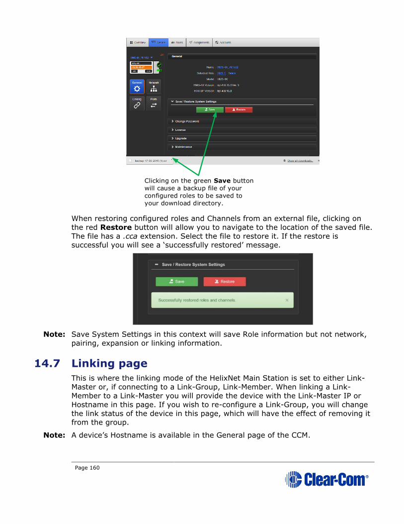
Page 160
When restoring configured roles and Channels from an external file, clicking on
the red Restore button will allow you to navigate to the location of the saved file.
The file has a .cca extension. Select the file to restore it. If the restore is successful you will see a ‘successfully restored’ message.
Note: Save System Settings in this context will save Role information but not network,
pairing, expansion or linking information.
14.7 Linking page
This is where the linking mode of the HelixNet Main Station is set to either Link-
Master or, if connecting to a Link-Group, Link-Member. When linking a Link-
Member to a Link-Master you will provide the device with the Link-Master IP or
Hostname in this page. If you wish to re-configure a Link-Group, you will change
the link status of the device in this page, which will have the effect of removing it from the group.
Note: A device’s Hostname is available in the General page of the CCM.
Clicking on the green Save button
will cause a backup file of your
configured roles to be saved to
your download directory.
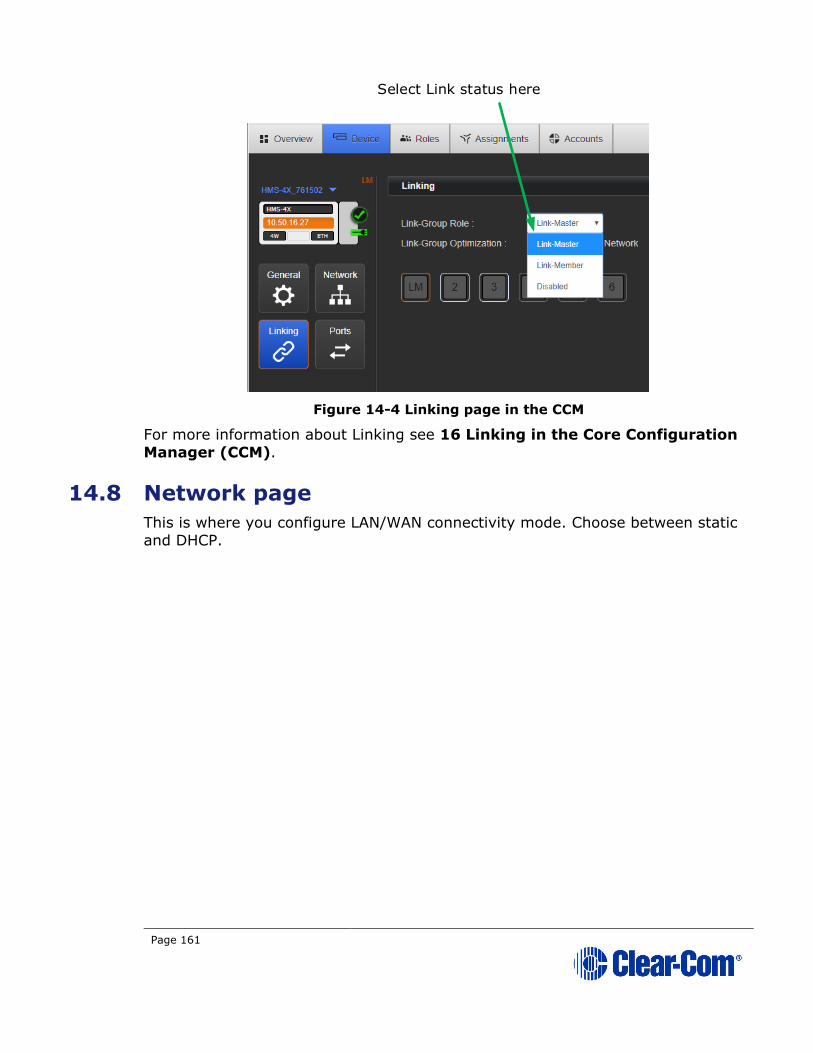
Page 161
Figure 14-4 Linking page in the CCM
For more information about Linking see 16 Linking in the Core Configuration
Manager (CCM).
14.8 Network page
This is where you configure LAN/WAN connectivity mode. Choose between static
and DHCP.
Select Link status here
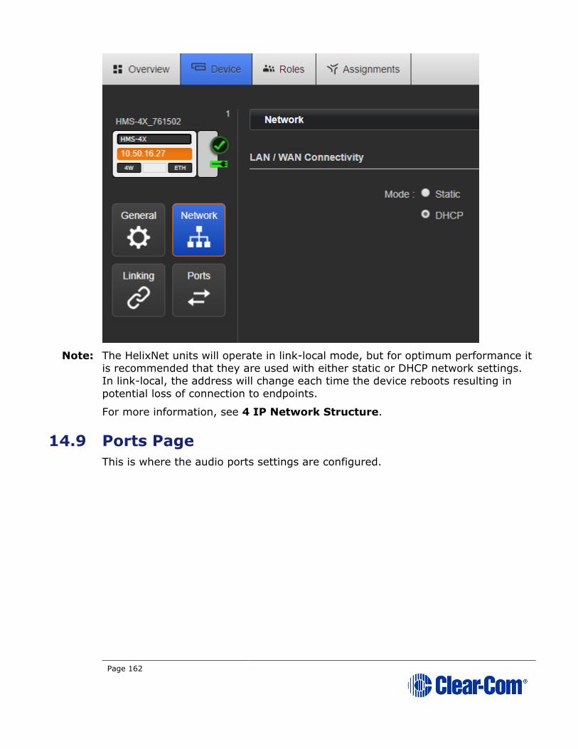
Page 162
Note: The HelixNet units will operate in link-local mode, but for optimum performance it
is recommended that they are used with either static or DHCP network settings.
In link-local, the address will change each time the device reboots resulting in
potential loss of connection to endpoints.
For more information, see 4 IP Network Structure.
14.9 Ports Page
This is where the audio ports settings are configured.

Page 163
14.9.1 Editing Module slots 1 – 3
Module slots 1 – 3 in the CCM correspond to the modules installed on the back of
your Main Station. If module configuration in the CCM does not match what is on
the device, a warning message will be given in the CCM.
For each module, chose between 3 types:
• None/Ethernet/Fiber
• 2-wire
• 4-wire
None/Ethernet/Fiber
There are no configuration options associated with this module type.
2-wire
For each XLR port (A & B) configure the following to connect 2 audio Channels to analogue Partylines:
Setting Options
Label Use to give the port a meaningful name
Channel
Assignment
Choose one from total Channels (12 or 24 depending on
license)
Program Output Mute (default)
Unmute
Mode Clear-Com (default)
RTS 2-pin
RTS 3-pin
Input Gain -3 dB – 3 dB (default = 0)
Output Gain -3 dB – 3 dB (default = 0)
Slot 1
Slot 2
Slot 3

Page 164
RMK Input Enabled (default)
Disabled
RMK Output Enabled (default)
Disabled
VOX Enabled (default)
Disabled
VOX Off Delay 0.5 s (default) – 4.0 s
GPO Trigger Enabled (default)
Disabled
Auto-Nulling Start or Stop
4-wire
For each RJ45 port (A & B) configure the following to connect two Channels to an
Eclipse Matrix or any 4-Wire device.
Setting Options
Label Use to give the port a meaningful name
Channel
Assignment
Choose one from total Channels (12 or 24 depending on
license)
Program Output Mute (default)
Unmute
Input Gain -3 dB – 3 dB (default = 0)
Output Gain -3 dB – 3 dB (default = 0)
VOX Enabled
Disabled (default)
VOX Off Delay 0.5 s (default) – 4.0 s
GPO Trigger Enabled
Disabled (default)

Page 165
14.10 Roles Page
To access the Roles page, select Roles from the top navigation bar. On this page
you will create, delete, clone and edit Roles.
Roles available for editing, cloning and configuration are in the left margin of the
page. Role parameters available for configuration are on the right of the page.
To create a Role , click the device type you require on the left hand side of the
page (Main Station, Remote Station, Speaker Station or beltpack), choose a
template (in the first instance this will be the Default role for that device) and
click ‘ADD’.
To edit a Role click on the required Role in the left of the page. When it is selected
for editing, it will have an orange highlight.
Note: Changes made to Roles here are live.

Page 166
Figure 14-5 The Roles page with example Roles
14.10.1 Audio Assignment
In HelixNet 3.0 or later, audio assignment is achieved in the Roles page. You will
assign audio to a Channel on a Keyset. For a description of a Keyset (available on
the front panel of all devices) see 2.1.1 Main Station/Remote Channel keyset
and display. A Main Station, a Remote Station and a Speaker Station have 4
Keysets on each device. Beltpacks have two Keysets on each device (beltpacks
can also have many Channels stacked on one key).
14.11 Assignments page
The Assignments page has three main functions in HelixNet 4.0. From this page in
the CCM you can:
• Change Channel names
Selected Role parameters available for configuration.
Click + to expand a section.
Roles available for editing.
Note: Orange highlight on selected Role
Click Key Assignment to assign a channel to a key

Page 167
• See a real-time, visual representation of devices and Roles in use. Any
changes to the configuration are reflected immediately in this page and
the working system.
• Add or remove Helixnet ports and LQ ports in and out of Helixnet
channels.
This page toggles between Hostname view and Roles view.

Page 168
Figure 14-6 Assignments Page
Arrows indicate direction
of input into Channel
Select Roles or
Hostname and/or
Hide Empty Channels
Click to change Channel nameClick Assignments button to see page
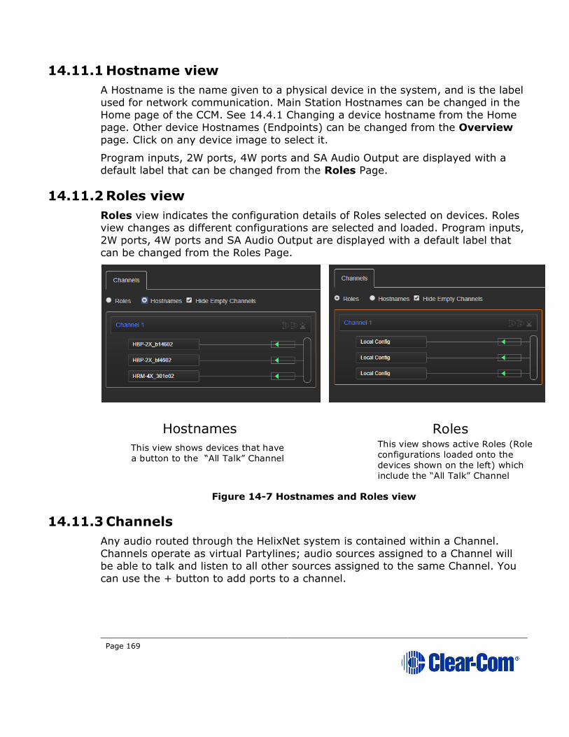
Page 169
14.11.1 Hostname view
A Hostname is the name given to a physical device in the system, and is the label
used for network communication. Main Station Hostnames can be changed in the
Home page of the CCM. See 14.4.1 Changing a device hostname from the Home
page. Other device Hostnames (Endpoints) can be changed from the Overview
page. Click on any device image to select it.
Program inputs, 2W ports, 4W ports and SA Audio Output are displayed with a
default label that can be changed from the Roles Page.
14.11.2 Roles view
Roles view indicates the configuration details of Roles selected on devices. Roles view changes as different configurations are selected and loaded. Program inputs,
2W ports, 4W ports and SA Audio Output are displayed with a default label that
can be changed from the Roles Page.
Figure 14-7 Hostnames and Roles view
14.11.3 Channels
Any audio routed through the HelixNet system is contained within a Channel.
Channels operate as virtual Partylines; audio sources assigned to a Channel will
be able to talk and listen to all other sources assigned to the same Channel. You
can use the + button to add ports to a channel.
Hostnames Roles
This view shows devices that have
a button to the All Talk Channel
This view shows active Roles (Role
configurations loaded onto the
devices shown on the left) which
include the All Talk Channel

Page 170
14.11.4 To rename a Channel
1) In the Assignments page, click on the blue Channel name to select it
2) Enter the new name.
3) Click the blue check mark or <Enter> to submit change.
Click to select

Page 171
15 Using the CCM to configure Roles
15.1 Editing Main Station roles
You can edit any Main Station Role including default Roles in the CCM.
15.1.1 Editing the Keyset
Each device has four Keysets, one for each Channel. The Keyset is used to control
the Channel. You can configure:
• Which Channel is assigned to the Keyset
• If the Talk key on the Keyset is latching or non-latching
1) From the drop-down list of Roles, select the Role you wish to edit.
2) Select Keyset.
Figure 15-1 Editing keysets
3) Select the key you wish to edit (Channel 1, 2, 3, or 4).
4) To assign a different Channel to the key, click Key Assignment.
Figure 15-2
Edit Key Assignment
Edit Talk key latch
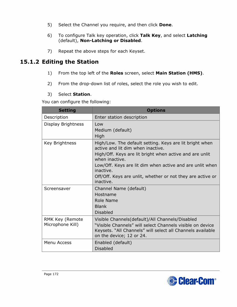
Page 172
5) Select the Channel you require, and then click Done.
6) To configure Talk key operation, click Talk Key, and select Latching (default), Non-Latching or Disabled.
7) Repeat the above steps for each Keyset.
15.1.2 Editing the Station
1) From the top left of the Roles screen, select Main Station (HMS).
2) From the drop-down list of roles, select the role you wish to edit.
3) Select Station.
You can configure the following:
Setting Options
Description Enter station description
Display Brightness Low
Medium (default)
High
Key Brightness High/Low. The default setting. Keys are lit bright when
active and lit dim when inactive.
High/Off. Keys are lit bright when active and are unlit
when inactive.
Low/Off. Keys are lit dim when active and are unlit when
inactive.
Off/Off. Keys are unlit, whether or not they are active or
inactive.
Screensaver Channel Name (default)
Hostname
Role Name
Blank
Disabled
RMK Key (Remote
Microphone Kill)
Visible Channels(default)/All Channels/Disabled
“Visible Channels” will select Channels visible on device
Keysets. “All Channels” will select all Channels available
on the device; 12 or 24.
Menu Access Enabled (default)
Disabled

Page 173
Setting Options
All Talk key talks to Visible Channels(default)/All Channels
“Visible Channels” will talk to Channels visible on device
Keysets. “All Channels” will talk to all Channels available
on the device (12 or 24 depending on your license).
4) For each setting, select the option you require.
15.1.3 Editing the Headset
1) From the top left of the Roles screen, select Main Station (HMS).
2) From the drop-down list of roles, select the role you wish to edit.
3) Select Headset.
You can configure the following:
Setting Options
Sidetone Gain Adjust slider control from -18dB to 0dB (Default -12dB)
Headphone Gain 0db (default) to 12dB
Headphone Limit Off
+6dB
0dB (default)
-6dB
Sidetone Control Tracking (default)
Non-Tracking
Disabled
HS Mic Type Electret(-15dB)
Dynamic (0dB) (default)
Dynamic (low)
4) For each setting, select the option you require.
15.1.4 Editing the Microphone
1) From the top left of the Roles screen, select Main Station (HMS).
2) From the drop-down list of roles, select the role you wish to edit.
3) Select Microphone.
You can configure the following:
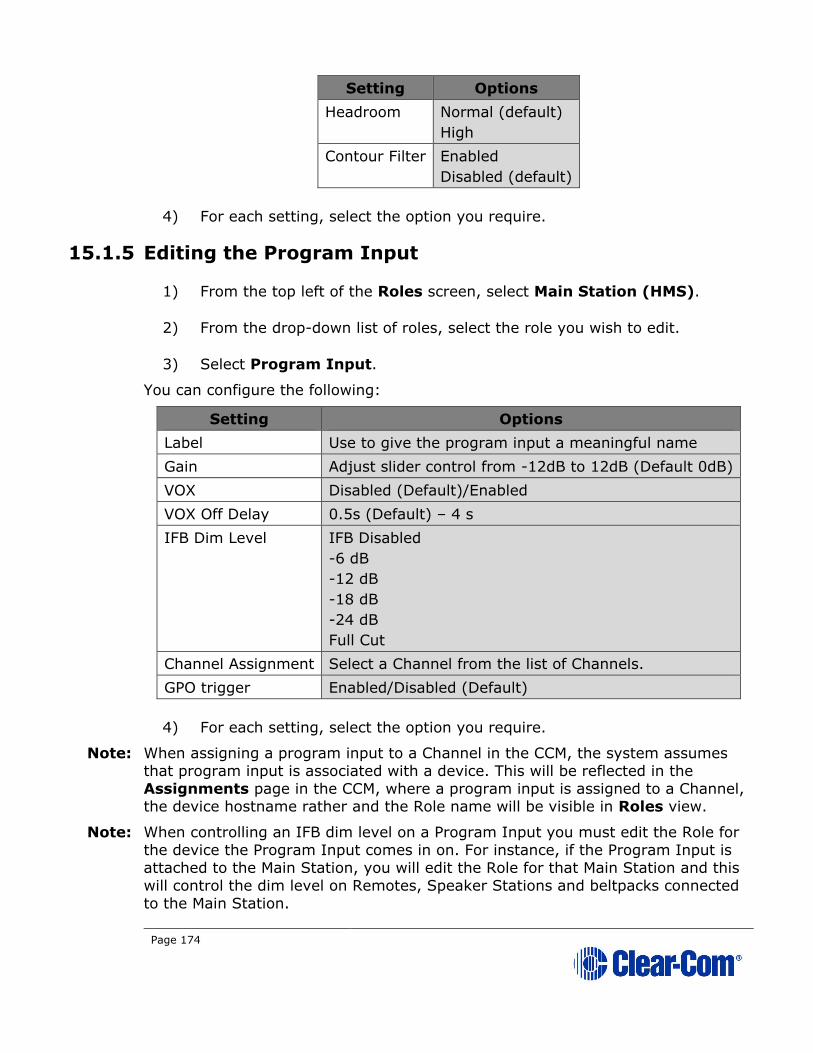
Page 174
Setting Options
Headroom Normal (default)
High
Contour Filter Enabled
Disabled (default)
4) For each setting, select the option you require.
15.1.5 Editing the Program Input
1) From the top left of the Roles screen, select Main Station (HMS).
2) From the drop-down list of roles, select the role you wish to edit.
3) Select Program Input.
You can configure the following:
Setting Options
Label Use to give the program input a meaningful name
Gain Adjust slider control from -12dB to 12dB (Default 0dB)
VOX Disabled (Default)/Enabled
VOX Off Delay 0.5s (Default) – 4 s
IFB Dim Level IFB Disabled
-6 dB
-12 dB
-18 dB
-24 dB
Full Cut
Channel Assignment Select a Channel from the list of Channels.
GPO trigger Enabled/Disabled (Default)
4) For each setting, select the option you require.
Note: When assigning a program input to a Channel in the CCM, the system assumes
that program input is associated with a device. This will be reflected in the
Assignments page in the CCM, where a program input is assigned to a Channel, the device hostname rather and the Role name will be visible in Roles view.
Note: When controlling an IFB dim level on a Program Input you must edit the Role for
the device the Program Input comes in on. For instance, if the Program Input is
attached to the Main Station, you will edit the Role for that Main Station and this
will control the dim level on Remotes, Speaker Stations and beltpacks connected
to the Main Station.
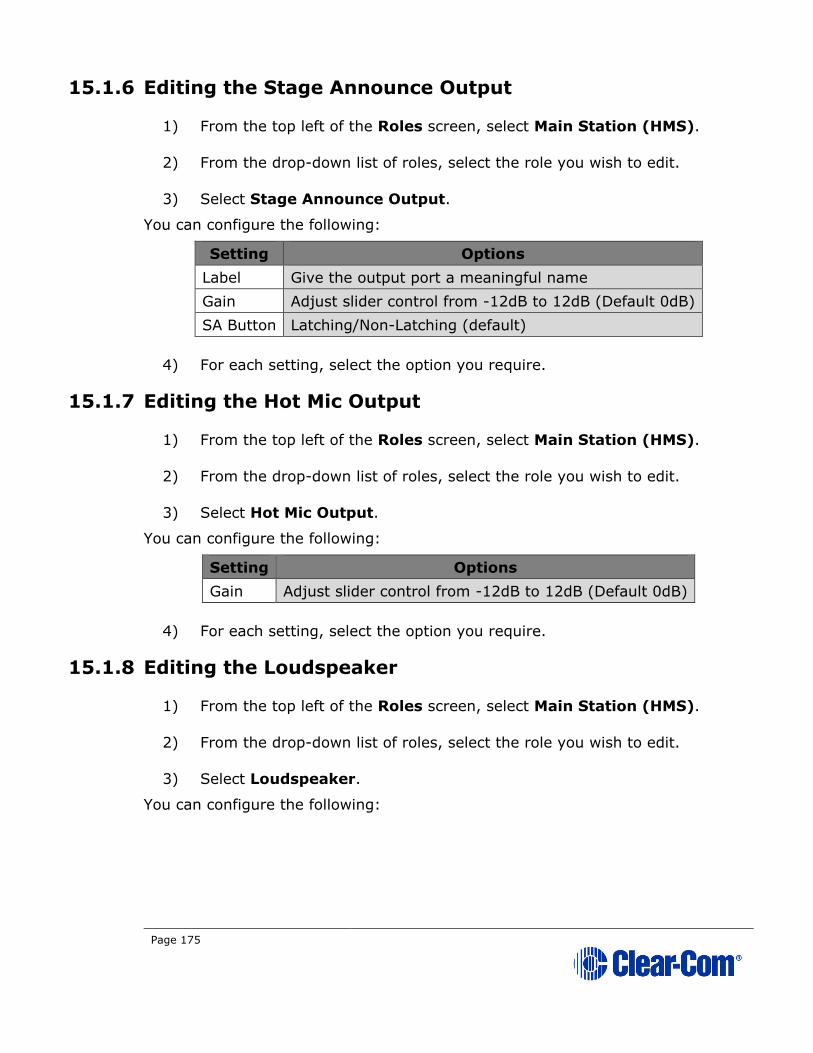
Page 175
15.1.6 Editing the Stage Announce Output
1) From the top left of the Roles screen, select Main Station (HMS).
2) From the drop-down list of roles, select the role you wish to edit.
3) Select Stage Announce Output.
You can configure the following:
Setting Options
Label Give the output port a meaningful name
Gain Adjust slider control from -12dB to 12dB (Default 0dB)
SA Button Latching/Non-Latching (default)
4) For each setting, select the option you require.
15.1.7 Editing the Hot Mic Output
1) From the top left of the Roles screen, select Main Station (HMS).
2) From the drop-down list of roles, select the role you wish to edit.
3) Select Hot Mic Output.
You can configure the following:
Setting Options
Gain Adjust slider control from -12dB to 12dB (Default 0dB)
4) For each setting, select the option you require.
15.1.8 Editing the Loudspeaker
1) From the top left of the Roles screen, select Main Station (HMS).
2) From the drop-down list of roles, select the role you wish to edit.
3) Select Loudspeaker.
You can configure the following:
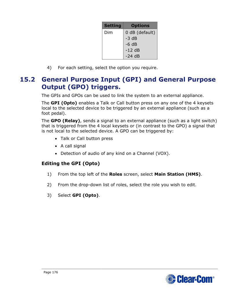
Page 176
Setting Options
Dim 0 dB (default)
-3 dB
-6 dB
-12 dB
-24 dB
4) For each setting, select the option you require.
15.2 General Purpose Input (GPI) and General Purpose Output (GPO) triggers.
The GPIs and GPOs can be used to link the system to an external appliance.
The GPI (Opto) enables a Talk or Call button press on any one of the 4 keysets
local to the selected device to be triggered by an external appliance (such as a
foot pedal).
The GPO (Relay), sends a signal to an external appliance (such as a light switch)
that is triggered from the 4 local keysets or (in contrast to the GPO) a signal that is not local to the selected device. A GPO can be triggered by:
• Talk or Call button press
• A call signal
• Detection of audio of any kind on a Channel (VOX).
Editing the GPI (Opto)
1) From the top left of the Roles screen, select Main Station (HMS).
2) From the drop-down list of roles, select the role you wish to edit.
3) Select GPI (Opto).

Page 177
4) For each GPI select the local keyset (1 – 4) and you wish to activate (Talk or Call).
Editing the GPO (Relay)
1) From the top left of the Roles screen, select Main Station (HMS).
2) From the drop-down list of roles, select the role you wish to edit.
3) Select GPO (Relay).
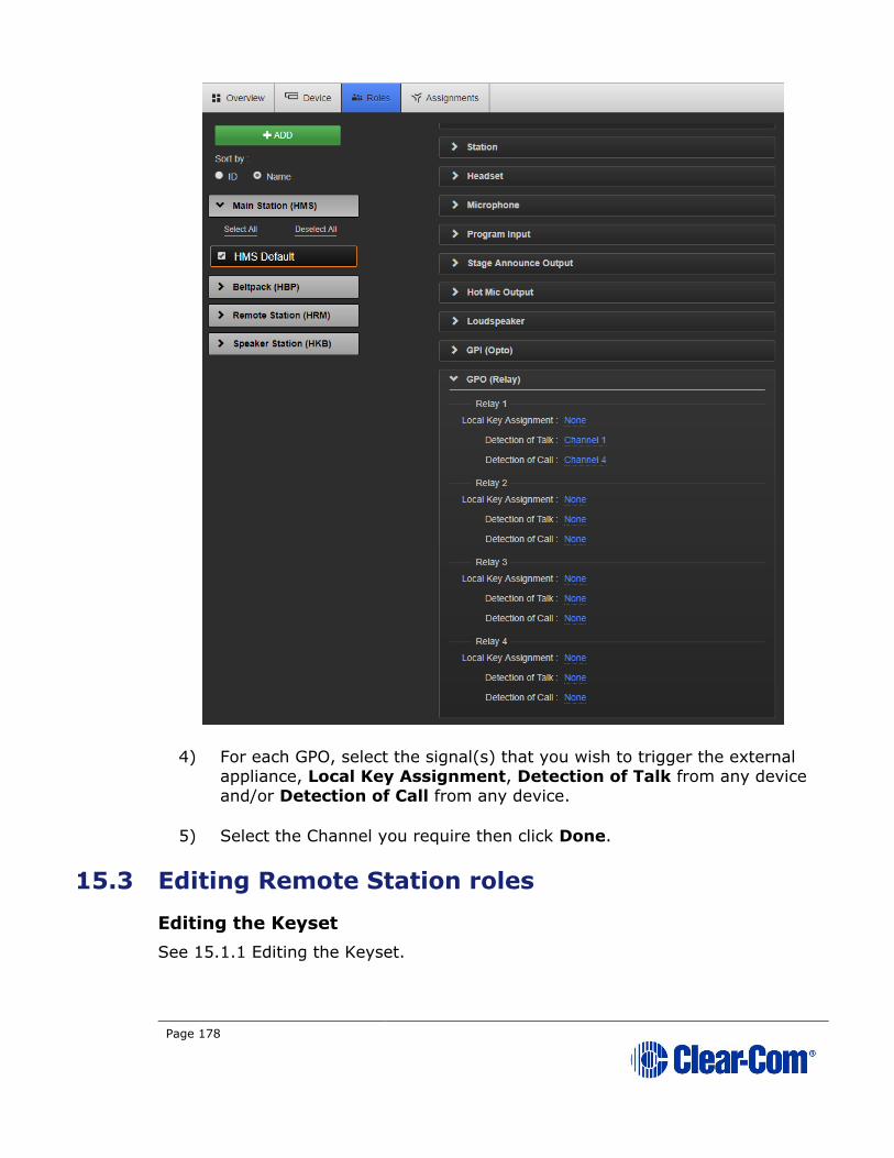
Page 178
4) For each GPO, select the signal(s) that you wish to trigger the external appliance, Local Key Assignment, Detection of Talk from any device
and/or Detection of Call from any device.
5) Select the Channel you require then click Done.
15.3 Editing Remote Station roles
Editing the Keyset
See 15.1.1 Editing the Keyset.

Page 179
15.3.1 Editing the Station
1) From the drop-down list of roles, select the role you wish to edit.
2) Select Station.
You can configure the following:
Setting Options
Description Enter station description
Display
Brightness
Low
Medium (default)
High
Key Brightness High/Low. The default setting. Keys are lit bright when active
and lit dim when inactive.
High/Off. Keys are lit bright when active and are unlit when
inactive.
Low/Off. Keys are lit dim when active and are unlit when
inactive.
Off/Off. Keys are unlit, whether or not they are active or
inactive.
Screensaver Channel Name (default)
Hostname
Role Name
Blank
Disabled
OPT (RMK)
Key
Disabled (Default)/All Channels/Visible Channels. This option allows you to enable RMK on remote stations. See 7.9 Using
the RMK [Remote Mic Kill] key
Menu Access Enabled (default)
Disabled
All Talk key
talks to:
Visible Channels (Default)/All Channels
3) For each setting, select the option you require.
Note: Each device has the capacity for either 12 or 24 Channels (depending on license).
These will all be enabled if you choose ‘All Channels’. “Visible Channels” enables
only those Channels selected and visible on device Keysets.
Editing the Headset
See 15.1.3 Editing the Headset.

Page 180
Editing the Microphone
See 15.1.4 Editing the Microphone.
Editing the Program Input/Audio In
See 15.1.5 Editing the Program Input
Editing the Stage Announce Output/Audio Out
See 15.1.6 Editing the Stage Announce Output
Editing the Hot Mic Output
See 15.1.7 Editing the Hot Mic Output.
Editing the Loudspeaker
See 15.1.8 Editing the Loudspeaker.
Editing the GPI (Opto)
15.2 General Purpose Input (GPI) and General Purpose Output (GPO) triggers.
15.4 Editing Speaker Station roles
Editing the Keyset
See 15.1.1 Editing the Keyset
15.4.1 Editing the Station
1) From the drop-down list of roles, select the role you wish to edit.
2) Select Station.
You can configure the following:
Setting Options
Description Enter station description
Display
Brightness
Low
Medium (default)
High
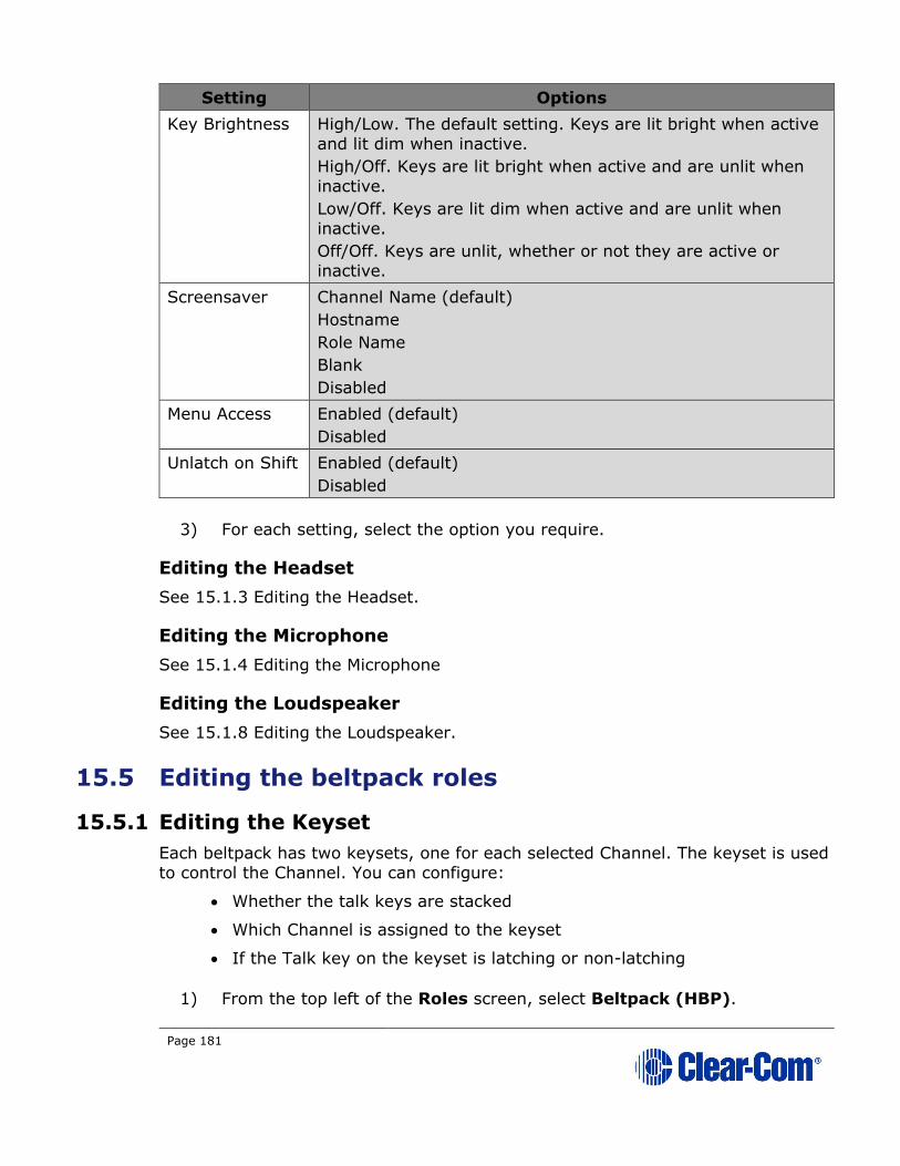
Page 181
Setting Options
Key Brightness High/Low. The default setting. Keys are lit bright when active
and lit dim when inactive.
High/Off. Keys are lit bright when active and are unlit when
inactive.
Low/Off. Keys are lit dim when active and are unlit when
inactive.
Off/Off. Keys are unlit, whether or not they are active or
inactive.
Screensaver Channel Name (default)
Hostname
Role Name
Blank
Disabled
Menu Access Enabled (default)
Disabled
Unlatch on Shift Enabled (default)
Disabled
3) For each setting, select the option you require.
Editing the Headset
See 15.1.3 Editing the Headset.
Editing the Microphone
See 15.1.4 Editing the Microphone
Editing the Loudspeaker
See 15.1.8 Editing the Loudspeaker.
15.5 Editing the beltpack roles
15.5.1 Editing the Keyset
Each beltpack has two keysets, one for each selected Channel. The keyset is used
to control the Channel. You can configure:
• Whether the talk keys are stacked
• Which Channel is assigned to the keyset
• If the Talk key on the keyset is latching or non-latching
1) From the top left of the Roles screen, select Beltpack (HBP).
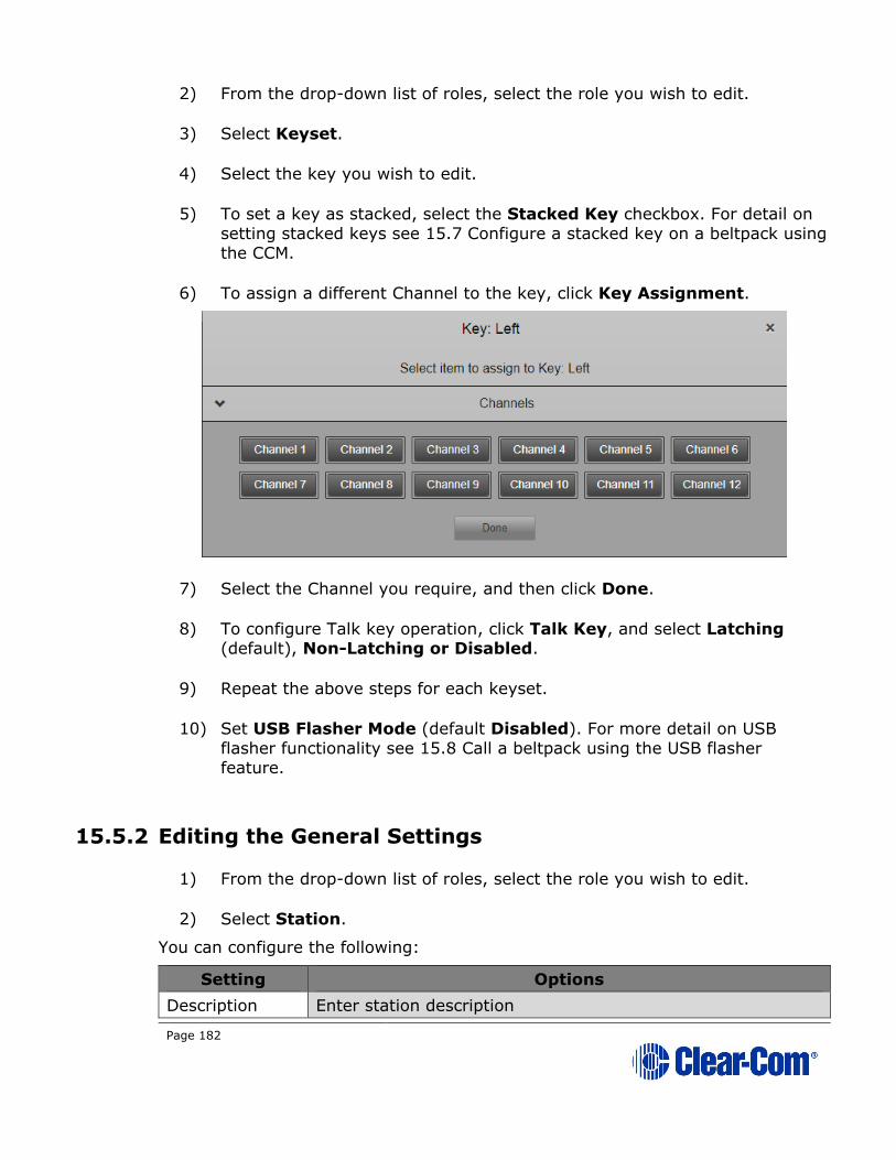
Page 182
2) From the drop-down list of roles, select the role you wish to edit.
3) Select Keyset.
4) Select the key you wish to edit.
5) To set a key as stacked, select the Stacked Key checkbox. For detail on
setting stacked keys see 15.7 Configure a stacked key on a beltpack using the CCM.
6) To assign a different Channel to the key, click Key Assignment.
7) Select the Channel you require, and then click Done.
8) To configure Talk key operation, click Talk Key, and select Latching (default), Non-Latching or Disabled.
9) Repeat the above steps for each keyset.
10) Set USB Flasher Mode (default Disabled). For more detail on USB
flasher functionality see 15.8 Call a beltpack using the USB flasher feature.
15.5.2 Editing the General Settings
1) From the drop-down list of roles, select the role you wish to edit.
2) Select Station.
You can configure the following:
Setting Options
Description Enter station description

Page 183
Display
Brightness
Low
Medium (default)
High
Key Brightness High/Low. The default setting. Keys are lit bright when active
and lit dim when inactive.
High/Off. Keys are lit bright when active and are unlit when
inactive.
Low/Off. Keys are lit dim when active and are unlit when
inactive.
Off/Off. Keys are unlit, whether or not they are active or
inactive.
Vibrate on Call Enabled
Disabled (default)
Rotate Display Enabled
Disabled (default)
Screensaver Channel Name (default)
Hostname
Role Name
Blank
Disabled
Menu Access Enabled (default)
Disabled
3) For each setting, select the option you require.
Editing the Headset
See 15.1.3 Editing the Headset.
Editing the Microphone
See 15.1.4 Editing the Microphone
15.6 Configure a stacked key on a beltpack using the
CCM
You can configure stacked keys on a beltpack, putting two or more Channels on
the same key. This enables the beltpack user to talk and listen to two groups simultaneously. Pressing the Talk or Call button on the beltpack will initiate a talk
or call to all the Channels on the stacked key. If any Channel user activates a call
to the beltpack, the Call label will flash and vibrate if enabled.
Beltpack stacked keys can only be configured through the Core Configuration
Manager (CCM).
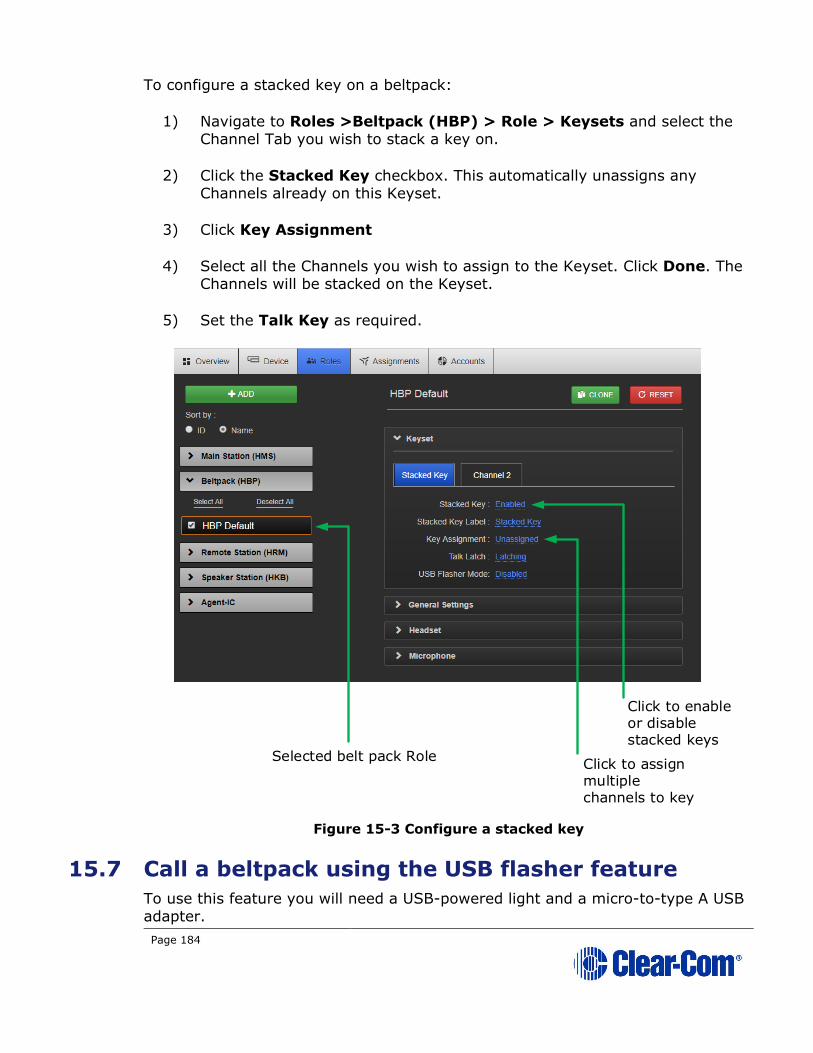
Page 184
To configure a stacked key on a beltpack:
1) Navigate to Roles >Beltpack (HBP) > Role > Keysets and select the Channel Tab you wish to stack a key on.
2) Click the Stacked Key checkbox. This automatically unassigns any Channels already on this Keyset.
3) Click Key Assignment
4) Select all the Channels you wish to assign to the Keyset. Click Done. The Channels will be stacked on the Keyset.
5) Set the Talk Key as required.
Figure 15-3 Configure a stacked key
15.7 Call a beltpack using the USB flasher feature
To use this feature you will need a USB-powered light and a micro-to-type A USB
adapter.
Selected belt pack Role
Click to enable or disable stacked keys
Click to assign multiple channels to key
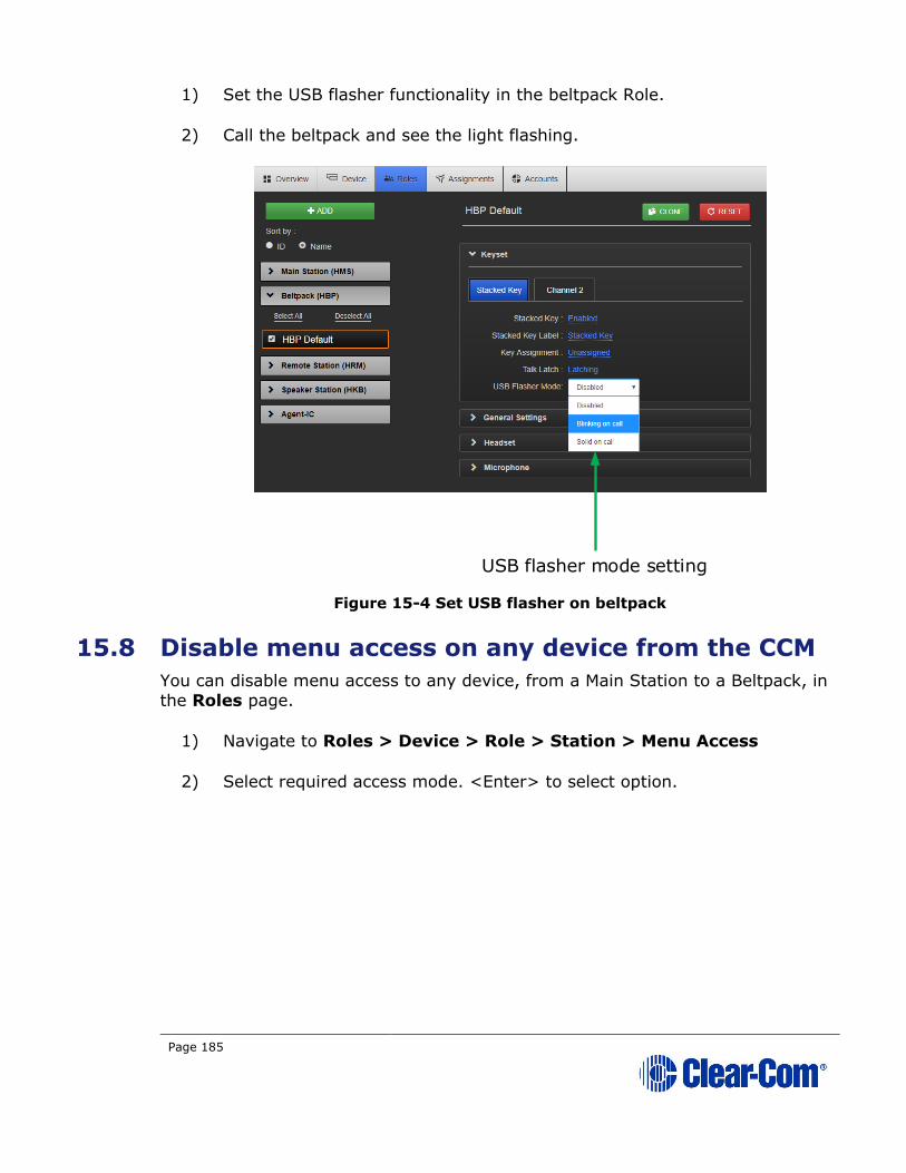
Page 185
1) Set the USB flasher functionality in the beltpack Role.
2) Call the beltpack and see the light flashing.
Figure 15-4 Set USB flasher on beltpack
15.8 Disable menu access on any device from the CCM
You can disable menu access to any device, from a Main Station to a Beltpack, in
the Roles page.
1) Navigate to Roles > Device > Role > Station > Menu Access
2) Select required access mode. <Enter> to select option.
USB flasher mode setting

Page 186
Figure 15-5 Enable/disable menu access
Go to Roles/Device/Station/Menu
Access and select required option
Selected device
Role has an orange
highlight
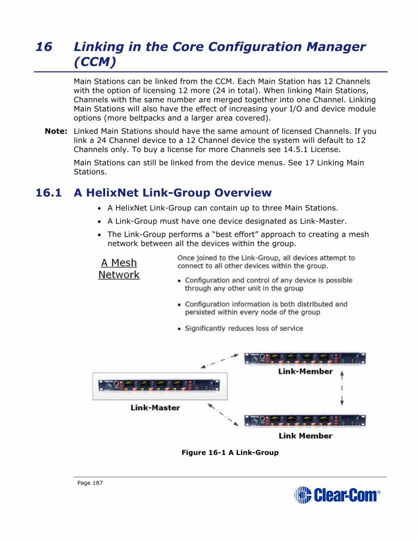
Page 187
16 Linking in the Core Configuration Manager
(CCM)
Main Stations can be linked from the CCM. Each Main Station has 12 Channels
with the option of licensing 12 more (24 in total). When linking Main Stations,
Channels with the same number are merged together into one Channel. Linking
Main Stations will also have the effect of increasing your I/O and device module options (more beltpacks and a larger area covered).
Note: Linked Main Stations should have the same amount of licensed Channels. If you
link a 24 Channel device to a 12 Channel device the system will default to 12
Channels only. To buy a license for more Channels see 14.5.1 License.
Main Stations can still be linked from the device menus. See 17 Linking Main Stations.
16.1 A HelixNet Link-Group Overview
• A HelixNet Link-Group can contain up to three Main Stations.
• A Link-Group must have one device designated as Link-Master.
• The Link-Group performs a “best effort” approach to creating a mesh
network between all the devices within the group.
Figure 16-1 A Link-Group

Page 188
16.1.1 The Link-Master
The Link-Master designation serves three main purposes:
1) It facilitates Link-Group membership.
2) It is the owner of configured Role information, meaning that Roles will only persist (be maintained consistently) if the Link-Master is operational.
3) It is responsible for the synchronization and distribution of both configuration (Roles) and device availability status throughout the Link-
Group.
Note: Clear-Com recommends that the IP address of the Link-Master is allocated statically. When allocated by DHCP, the IP address can change. If this happens
the Link-Members will no longer be able to reach the Link-Master device, and Role
information may not be persisted.
Note: Any device can be set to Link-Master or Link-Member. The default setting for
HelixNet linking mode is Link Disabled.
Note: Linked Main Stations need 2 – 5 Mbps of bandwidth.
16.1.2 The Link-Members
HelixNet devices that are not identified as master will have the designation of
Link-Member. Joining a device to a Link-Group requires that device to be set to Link-Member which will prompt the user to enter the IP address of the Link-
Master.
16.2 Device configuration in the CCM
Note: Any IP connectivity requires an Ethernet or Fiber module fitted to the Main Station.
Once the units have joined a Link-Group, the devices can be configured either
directly or by proxy. The host device is the unit which a browser is currently
directed to.
The Home button will always take you to the host device’s configuration page.
• Proxy configuration can be accomplished by clicking on any device within
the Overview page.
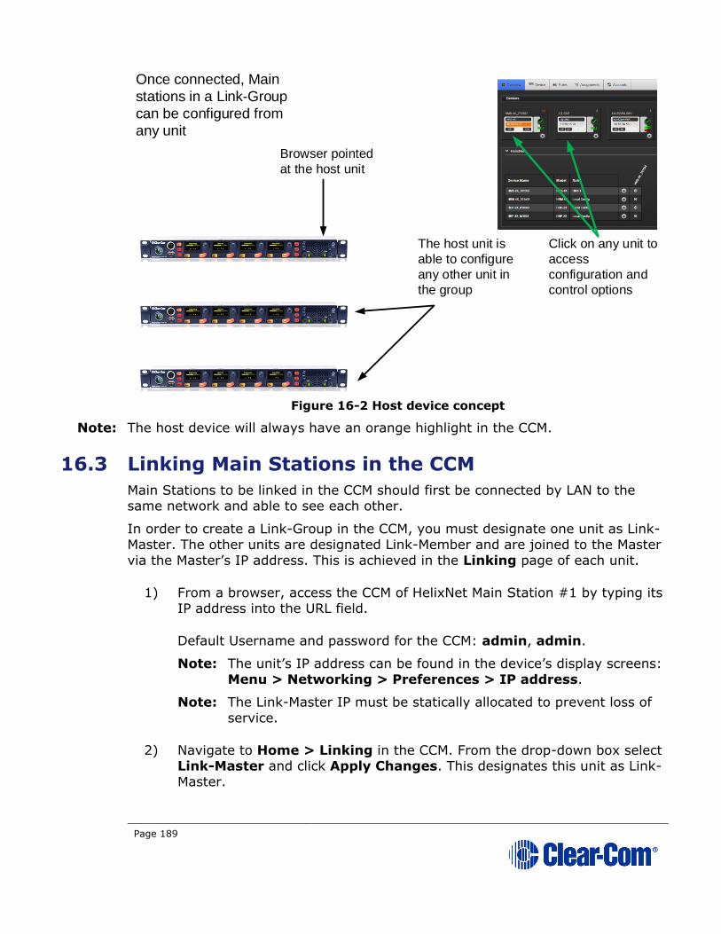
Page 189
Figure 16-2 Host device concept
Note: The host device will always have an orange highlight in the CCM.
16.3 Linking Main Stations in the CCM
Main Stations to be linked in the CCM should first be connected by LAN to the same network and able to see each other.
In order to create a Link-Group in the CCM, you must designate one unit as Link-
Master. The other units are designated Link-Member and are joined to the Master
via the Master’s IP address. This is achieved in the Linking page of each unit.
1) From a browser, access the CCM of HelixNet Main Station #1 by typing its IP address into the URL field.
Default Username and password for the CCM: admin, admin.
Note: The unit’s IP address can be found in the device’s display screens:
Menu > Networking > Preferences > IP address.
Note: The Link-Master IP must be statically allocated to prevent loss of
service.
2) Navigate to Home > Linking in the CCM. From the drop-down box select Link-Master and click Apply Changes. This designates this unit as Link-
Master.
Once connected, Main
stations in a Link-Group
can be configured from
any unit
Browser pointed
at the host unit
The host unit is
able to configure
any other unit in
the group
Click on any unit to
access
configuration and
control options

Page 190
Note: The default linking mode is: Link Disabled. When a device has
been designated either Link Master or Link Member it will be
looking for a pairing and a link icon will flash in the device screens.
Linking Disabled prevents this.
3) From a new browser window, access the CCM of device #2 by typing the unit’s IP address into the URL field.
You will have to enter the username and password for the device (Default, admin, admin)
4) Navigate to Home > Linking and select Link-Member from the drop down box.
5) You will be prompted for the IP address (or hostname) of the Link-Master. Within the Master IP address field, enter the IP address of device #1. Click
on blue check mark or <ENTER> key to submit.
Select Link status here
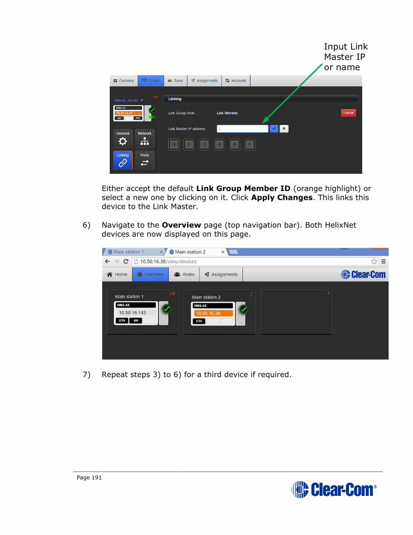
Page 191
Either accept the default Link Group Member ID (orange highlight) or select a new one by clicking on it. Click Apply Changes. This links this
device to the Link Master.
6) Navigate to the Overview page (top navigation bar). Both HelixNet devices are now displayed on this page.
7) Repeat steps 3) to 6) for a third device if required.
Input Link Master IP or name

Page 192
17 Linking Main Stations (cabling and linking
from device menus)
This chapter describes how to link Main Stations using the device menus rather
than the Core Configuration Manager. You can connect Main Stations directly
using Ethernet or Fiber, or connect them over a LAN via Ethernet.
Main Station linking is achieved using interface modules fitted to the extension bay of the Main Station. There are two modules:
• Ethernet interface module (HLI-ET2). This module provides an Ethernet
connection between Main Stations.
• Fiber interface module (HLI-FBS). This module provides a Fiber
connection between Main Stations.
Each Main Station has 12 Channels, and can connect up to 20 beltpacks.
Note: If you change the network topology between any two stations, you must reboot
the stations.
Warning: Both ports are configured to bridge traffic from one port
to the other in order to work in daisy-chain. Spanning Tree Protocol
is not enabled on those ports, therefore do not connect them both to the same network.
17.1 Linking scenarios
Main Stations are connected together using CAT, CAT5e or CAT6 shielded cable. They can also be connected using fiber. There are various topologies that you can
create. Some of these are illustrated below.
17.1.1 Linking two Main Stations over LAN
1) Insert an HLI-ET2 Ethernet interface module in each station. Use any of the three slots available.
Note: Ensure that the Main Station is powered down before inserting modules.
2) Connect a regular Ethernet cable (for example, CAT5, CAT5e, CAT6, CAT6e) from one HLI-ET2 port on one station to one HLI-ET2 port on the
other station.
3) Power up both stations. Verify that the green LED on each HLI-ET2 port is flashing.
4) On one HMS go to Networking->Linking->Link Mode menu and select Master.

Page 193
5) On the other HMS go to Networking->Linking->Link Mode and select Member. Then in Networking->Link to Master select the Master HMS
you identified in the previous step..
Note: In HelixNet 3.0 or later each Main Station has 12 Channels. Linking Main Stations
will have the effect of giving you more I/O and module options.
Note: You should see a Link icon on the Main Station display.
Figure 17-1: Linking two stations over LAN
17.1.2 Linking two Main Stations with Fiber
1) Insert an HLI-FBS Fiber interface module in each station. Use any of the three slots available.
Note: Ensure that the Main Station is powered down before
inserting modules.
2) Ensure that an SFP Transceiver is connected into one HLI-FBS module port on each station.
3) Connect Two Fibers from one HLI-FBS port on one station to one HLI-FBS port on the other station. If using Duplex LC/SC connectors, make sure that Tx on one goes to Rx on the other.
4) Power up both stations. Verify that the green LED on each HLI- FBS port is flashing.
5) On one HMS go to Networking->Linking->Link Mode menu and select Master.
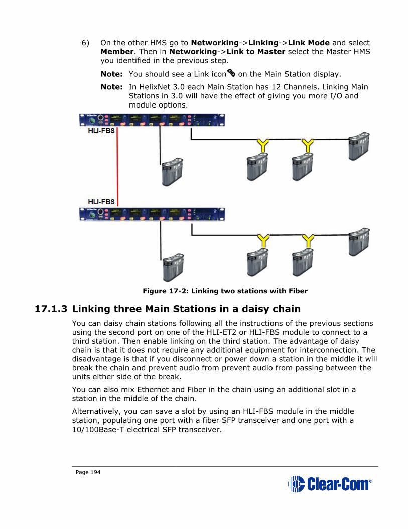
Page 194
6) On the other HMS go to Networking->Linking->Link Mode and select Member. Then in Networking->Link to Master select the Master HMS
you identified in the previous step.
Note: You should see a Link icon on the Main Station display.
Note: In HelixNet 3.0 each Main Station has 12 Channels. Linking Main
Stations in 3.0 will have the effect of giving you more I/O and
module options.
Figure 17-2: Linking two stations with Fiber
17.1.3 Linking three Main Stations in a daisy chain
You can daisy chain stations following all the instructions of the previous sections
using the second port on one of the HLI-ET2 or HLI-FBS module to connect to a
third station. Then enable linking on the third station. The advantage of daisy
chain is that it does not require any additional equipment for interconnection. The disadvantage is that if you disconnect or power down a station in the middle it will
break the chain and prevent audio from prevent audio from passing between the
units either side of the break.
You can also mix Ethernet and Fiber in the chain using an additional slot in a
station in the middle of the chain.
Alternatively, you can save a slot by using an HLI-FBS module in the middle
station, populating one port with a fiber SFP transceiver and one port with a
10/100Base-T electrical SFP transceiver.
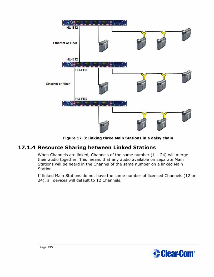
Page 195
Figure 17-3: Linking three Main Stations in a daisy chain
17.1.4 Resource Sharing between Linked Stations
When Channels are linked, Channels of the same number (1 – 24) will merge
their audio together. This means that any audio available on separate Main
Stations will be heard in the Channel of the same number on a linked Main
Station.
If linked Main Stations do not have the same number of licensed Channels (12 or
24), all devices will default to 12 Channels.
Page 196
18 Pairing Remote Stations, Speaker Stations
and HXII-BP-X4 beltpacks to the Main
Station
This chapter describes how to pair Remote and Speaker Stations to Main Stations.
You can connect Remote and Speaker Stations on one of the Digital Intercom Lines, point-to-point to a Main Station Ethernet interface module (HLI-ET2) or
over an IP network.
Linking to a Main Station over an IP network requires an Ethernet interface
module fitted to the extension bay of the Main Station (HLI-ET2).
Note: If the IP address on a Remote Station or Speaker Station changes, you must either reboot the Remote Station or disable and then re-enable the DHCP on the
Remote Station.
Warning: Digital intercom lines and the Ethernet connections are
mutually exclusive on Remote and Speaker Stations. If both are
connected it will be detected as a fault, communication over both
ports will stop and both status LEDs will blink RED. This requires a reboot of the station using Administration > Reset > Reboot
Warning: When changing the connection from digital intercom
line to Ethernet or vice-versa, you must disconnect one cable and
then wait until the unit has detected a loss of connection before
connecting the other cable. Otherwise, they will briefly be detected as both connected.
Warning: When changing the power connections to a Remote
Station, a network storm error message may appear. If so,
disconnect the power cable, and reboot the Remote Station.

Page 197
18.1 Pairing scenarios
There are various topologies that you can create. Some of these are illustrated
below.
18.1.1 Digital Partyline Intercom
Remote and Speaker Stations have Digital Intercom 3-pin XLR connectors (female and male) and can connect to Main Stations along with beltpacks.
Note: A Remote or a Speaker Station draws current equivalent to three beltpacks when
the loudspeaker is in use. If the Remote or Speaker Station is locally powered
using a power supply, it does not draw current from the digital intercom line.
1) Connect an XLR cable from a Main Station to the Remote or Speaker Station.
2) Power up the Main Station and verify that the Line 1 and Line 2 status LED are green on Main Station.
3) On a Remote Station you can verify that the Line status LED is steady green.
Figure 18-1 Connecting devices by cable

Page 198
18.1.2 Ethernet point-to-point link
Remote Stations, Speaker Stations and HXII-BP-X4 beltpacks have RJ45 Ethernet
connectors and can connect to Main Stations over Ethernet.
1) Insert an HLI-ET2 Ethernet interface module in the Main Station. Use any of the three slots available.
Note: Ensure that the Main Station is powered down before
inserting modules.
2) Connect a regular Ethernet cable (for example, CAT5, CAT5e, CAT6, CAT6e) from one HLI-ET2 port on one station to the Remote or Speaker
Station.
3) Connect an external AC/DC power adapter to the Remote or Speaker Station
4) Power up both Stations. Verify that the green LEDs on the HLI-ET2 port and on the Remote or Speaker Station are on.
5) Go to Networking->Pair to Station->By Name on the Remote or Speaker Station. You should see one entry indicating that the Remote or
Speaker Station has properly detected the Main Station. Select this entry.
6) Go to Station Settings->Keyset Assign and assign Channels to any keyset, or use the CCM to create Roles.

Page 199
18.1.3 Local IP Network
1) Insert an HLI-ET2 Ethernet interface module into the Main Station. Use any of the three slots available.
Note: Ensure that the Main Station is powered down before
inserting modules.
2) Connect a regular Ethernet cable (for example, CAT5, CAT5e, CAT6, CAT6e) from one HLI-ET2 port to an Ethernet Switch and connect Remote
or Speaker Stations to Ethernet Switch as well.
3) Connect an external AC/DC power adapter to the Remote or Speaker Station or connect them on a Power over Ethernet (PoE) port on the
Ethernet Switch.
4) Power up all Stations. Verify that the green LED on the HLI-ET2 port and on the Remote or Speaker Station is on.

Page 200
5) Go to Networking->Pair to Station->By Name on each Remote and Speaker Station. You should see one entry indicating that the Remote or
Speaker Station has properly detected the Main Station. Select this entry.
6) Go to Station Settings->Keyset Assign and assign Channels to any keyset, or use the CCM to create Roles.
18.1.4 Remote IP Network
Remote and Speaker Stations can connect to a Main Station that is not within the
same network Broadcast Domain.
1) Insert an HLI-ET2 Ethernet interface module in the Main Station. Use any of the three slots available.
Note: Ensure that the Main Station is powered down before
inserting modules.
2) Connect a regular Ethernet cable (for example, CAT5, CAT5e, CAT6, CAT6e) from one HLI-ET2 port to a Router/Gateway. Make sure you know
the Gateway IP address for that first subnet.
3) Connect Remote or Speaker Stations to a Router/Gateway. Make sure you
know the Gateway IP address for that second subnet.
4) Connect an external AC/DC power adapter to the Remote or Speaker
Station or connect them on a Power over Ethernet (PoE) port on the Ethernet Switch.
5) Power up all Stations. Verify that the green LED on the HLI-ET2 port and on the Remote or Speaker Station is on.
HKB-2X (with
Power Supply)
HRM-4X (PoE)
HMS-4X
PoE Ethernet
Switch
Ethernet
Switch
HKB-2X (with
Power Supply)
EthernetPoE Ethernet
Powerline
Y Connector

Page 201
6) On the Main Station, go to Networking->Preferences->IP Address and note the IP address of the Main Station. Make sure that Networking-
>Preferences->Gateway and Networking->Preferences->Subnet
match that of your local subnet, including the Gateway setting.
7) On each Remote and Speaker Station make sure that all Networking > Preferences match that of your remote subnet, including the Gateway
setting.
8) On each Remote and Speaker Station go to Networking->Link to Station->By Address and enter the IP address of the Main Station.
9) Go to Station Settings->Keyset Assign and assign Channels to any keyset, or use the CCM to create Roles.
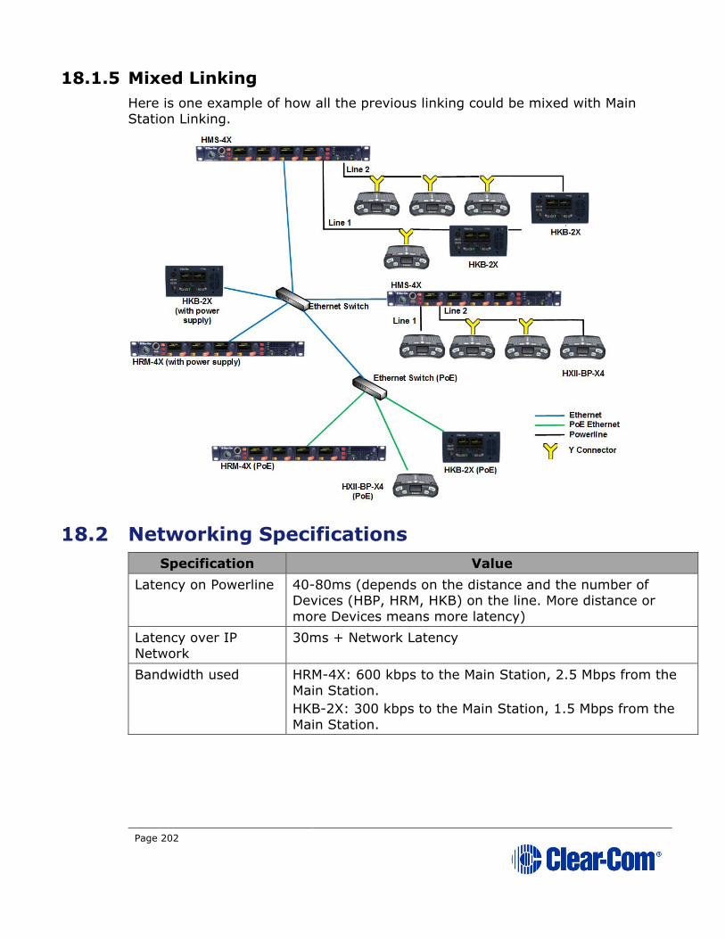
Page 202
18.1.5 Mixed Linking
Here is one example of how all the previous linking could be mixed with Main
Station Linking.
18.2 Networking Specifications
Specification Value
Latency on Powerline 40-80ms (depends on the distance and the number of Devices (HBP, HRM, HKB) on the line. More distance or
more Devices means more latency)
Latency over IP
Network
30ms + Network Latency
Bandwidth used HRM-4X: 600 kbps to the Main Station, 2.5 Mbps from the
Main Station.
HKB-2X: 300 kbps to the Main Station, 1.5 Mbps from the
Main Station.

Page 203
IPv4 UDP Port 6001 (Digital Intercom)
UDP Port 5353 (mDNS)
TCP Port 6001 (Digital Intercom)
TCP Port 655 (HMS linking)
TCP Port 80 (HTML, CCM, Expansion)
TCP Port 6000 (Pairing)

Page 204
19 Connecting to Other Intercom Systems
This chapter provides basic guidance on connecting your HelixNet Partyline system to a range of other intercom systems, including:
• Two-wire cabled Partyline systems (RTS and Clear-Com Encore®).
• Two-wire / four-wire wireless systems (Tempest, CellCom® /
FreeSpeak®, and the DX210).
• Digital matrix systems (Eclipse® MVX four-wire).
• Two-way radio systems.
• Linking to LQ devices.
The HMX-4X Main Station is connected to these systems using the optional Two-
wire and Four-wire interface modules.
19.1 Connecting LQ to HelixNet
19.1.1 About LQ™
LQ™ linking facilitates interfacing to any 2-wire partyline, 4-wire and 4-
wire+GPIO endpoints either local or remote over any IP network.
The product line provides a unique combination of low latency with exceptional
audio quality and an intuitive, easy to use design.
19.2 LQ to HelixNet connectivity
Linking one or more LQ units to a HelixNet Main Station (HMS) in a Link-Group is
a way of greatly increasing the number of I/O interfaces available in your HelixNet
intercom system.
Linking HelixNet and LQ also brings Agent-IC, SIP and Eclipse (IVC) connectivity
into your HelixNet system.
19.2.1 HelixNet/LQ Link-Group
Once an LQ unit is linked to an HMS in a Link-Group, all ports on the LQ unit are
visible in the CCM and available to be placed in a HelixNet Channel. Once a port is
in a Channel, audio from that port can be routed anywhere within the system.
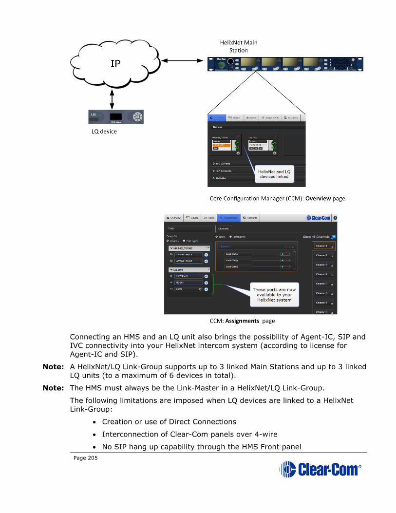
Page 205
Connecting an HMS and an LQ unit also brings the possibility of Agent-IC, SIP and
IVC connectivity into your HelixNet intercom system (according to license for
Agent-IC and SIP).
Note: A HelixNet/LQ Link-Group supports up to 3 linked Main Stations and up to 3 linked
LQ units (to a maximum of 6 devices in total).
Note: The HMS must always be the Link-Master in a HelixNet/LQ Link-Group.
The following limitations are imposed when LQ devices are linked to a HelixNet
Link-Group:
• Creation or use of Direct Connections
• Interconnection of Clear-Com panels over 4-wire
• No SIP hang up capability through the HMS Front panel
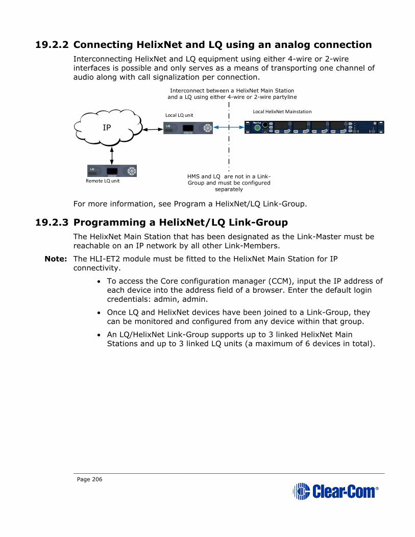
Page 206
19.2.2 Connecting HelixNet and LQ using an analog connection
Interconnecting HelixNet and LQ equipment using either 4-wire or 2-wire
interfaces is possible and only serves as a means of transporting one channel of
audio along with call signalization per connection.
For more information, see Program a HelixNet/LQ Link-Group.
19.2.3 Programming a HelixNet/LQ Link-Group
The HelixNet Main Station that has been designated as the Link-Master must be
reachable on an IP network by all other Link-Members.
Note: The HLI-ET2 module must be fitted to the HelixNet Main Station for IP
connectivity.
• To access the Core configuration manager (CCM), input the IP address of each device into the address field of a browser. Enter the default login
credentials: admin, admin.
• Once LQ and HelixNet devices have been joined to a Link-Group, they
can be monitored and configured from any device within that group.
• An LQ/HelixNet Link-Group supports up to 3 linked HelixNet Main
Stations and up to 3 linked LQ units (a maximum of 6 devices in total).
IP
Interconnect between a HelixNet Main Station and a LQ using either 4-wire or 2-wire partyline
Remote LQ unit
Local LQ unitLocal HelixNet Mainstation
HMS and LQ are not in a Link-Group and must be configured
separately

Page 207
19.2.4 Creating a HelixNet/LQ Link-Group
1) To access the HelixNet Core Configuration Manager, enter the IP address of the HelixNet Main Station, as displayed on the front panel, into the
address field of your browser. If the unit is reachable over your network,
this will take you to the Overview page of the CCM that is served by the unit.
Note: Default username and password for the CCM: admin, admin.
2) Ensure the HelixNet device is set to Link-Master in the CCM of the Main Station. Navigate to Device/Linking/Link-Group Role.
Note: Default Link-Group Role for an HMS is Disabled.
Note: The host device is the device your browser is currently pointing to.
LAN/WAN
HelixNet Mainstation: Link-Master #1
HLI-ET2 Ethernet module
LQ-R #3: Link-Member
LQ #2: Link-Member
HelixNet/LQ Link-Group Core Configuration Manager (CCM)
All devices in Link-Group connected to network with Cat5/6
cable
Audio can be routed to/from
any port on any device
within the Link-Group
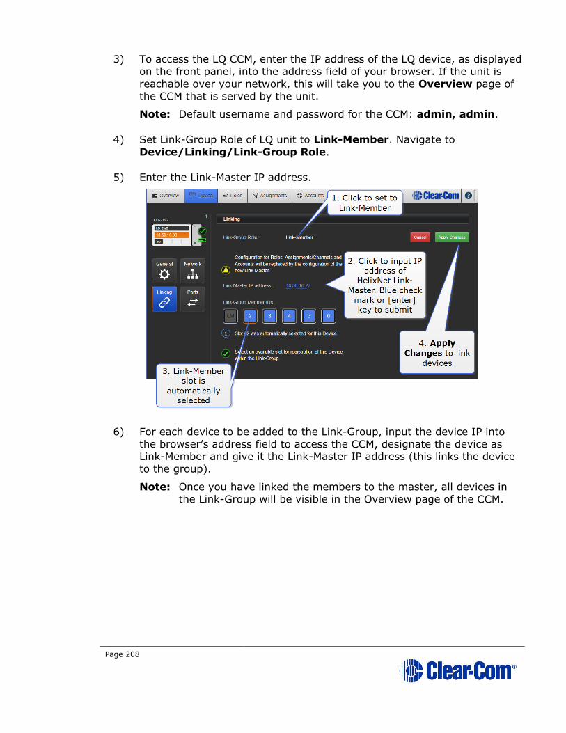
Page 208
3) To access the LQ CCM, enter the IP address of the LQ device, as displayed on the front panel, into the address field of your browser. If the unit is
reachable over your network, this will take you to the Overview page of
the CCM that is served by the unit.
Note: Default username and password for the CCM: admin, admin.
4) Set Link-Group Role of LQ unit to Link-Member. Navigate to
Device/Linking/Link-Group Role.
5) Enter the Link-Master IP address.
6) For each device to be added to the Link-Group, input the device IP into
the browser’s address field to access the CCM, designate the device as Link-Member and give it the Link-Master IP address (this links the device
to the group).
Note: Once you have linked the members to the master, all devices in
the Link-Group will be visible in the Overview page of the CCM.
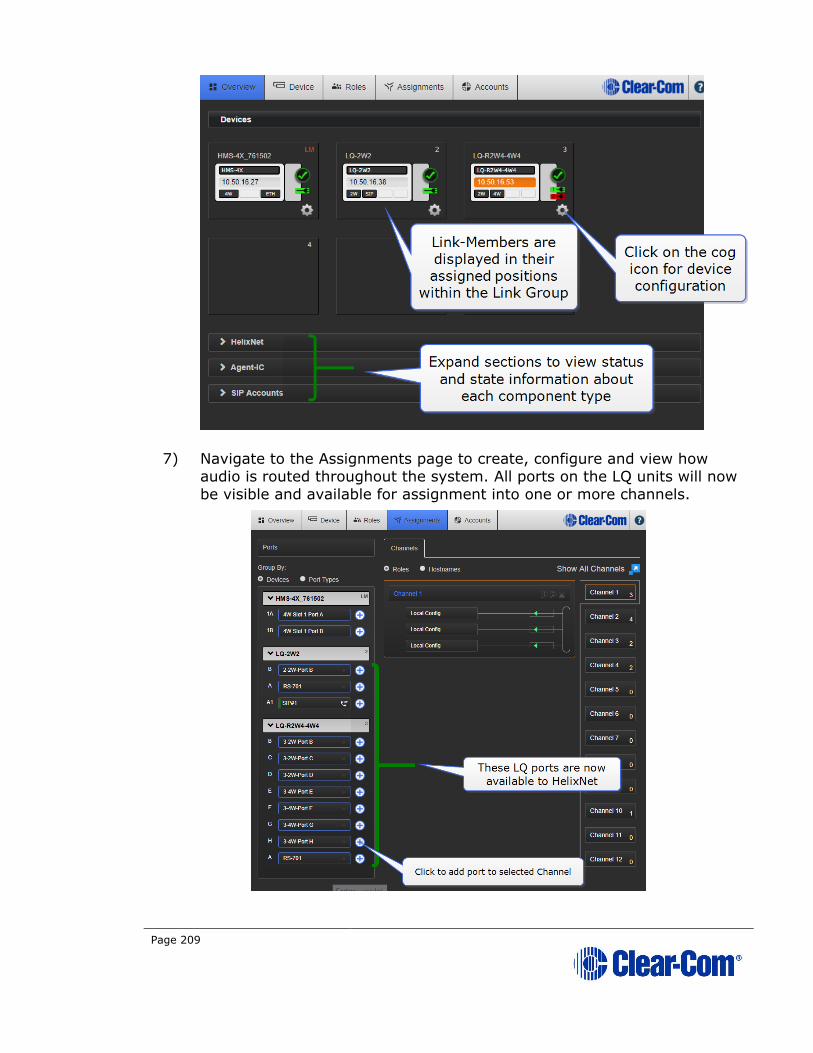
Page 209
7) Navigate to the Assignments page to create, configure and view how audio is routed throughout the system. All ports on the LQ units will now
be visible and available for assignment into one or more channels.

Page 210
19.3 Connecting HelixNet Partyline to Encore®
19.3.1 About Encore
Encore is the plug-and-play analog two-wire Partyline system from Clear-Com.
Clear-Com Encore is widely used in theaters, schools, local broadcast stations,
churches and other small to mid-size live productions.
Two and four Channel versions of the Encore Main Stations and Remote Stations
are available.
Tip: For more information about Encore, see your Encore documentation or visit the Analog Partyline Intercom pages on the Clear-Com website:
http://www.clearcom.com/product/Partyline.

Page 211
19.3.2 Quick reference: Connecting to Encore
Figure 19-1: Two-wire connection to Encore
HMS-4X Main Station 2W Encore Main Station (MS-70x)
Configure the 2W moduleConfigure the port as Clear-ComRun auto-null
2W
Two-wire connection to Encore
HMS-4X Main Station 2W
Power supply
Or
Encore Main Station (MS-70x)
Encore Remote Station (RM-70x)
Standard microphone cable3-pin XLR connectors
Line must be powered (Remote Station provides no power).
2W
Ensure connection is terminated (switch beside connector is on)Adjust nulling using Sidetone Adjust and Listen Adjust controls
Encore Main Station powers the line
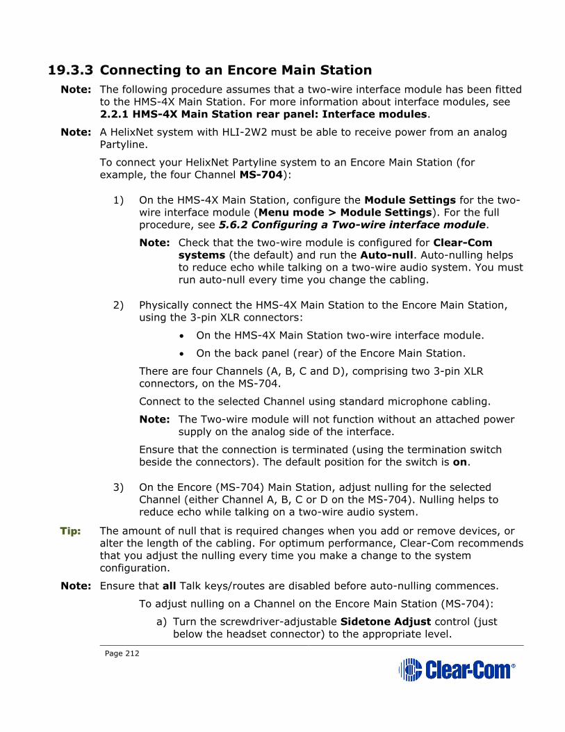
Page 212
19.3.3 Connecting to an Encore Main Station
Note: The following procedure assumes that a two-wire interface module has been fitted
to the HMS-4X Main Station. For more information about interface modules, see
2.2.1 HMS-4X Main Station rear panel: Interface modules.
Note: A HelixNet system with HLI-2W2 must be able to receive power from an analog
Partyline.
To connect your HelixNet Partyline system to an Encore Main Station (for
example, the four Channel MS-704):
1) On the HMS-4X Main Station, configure the Module Settings for the two-wire interface module (Menu mode > Module Settings). For the full
procedure, see 5.6.2 Configuring a Two-wire interface module.
Note: Check that the two-wire module is configured for Clear-Com
systems (the default) and run the Auto-null. Auto-nulling helps to reduce echo while talking on a two-wire audio system. You must
run auto-null every time you change the cabling.
2) Physically connect the HMS-4X Main Station to the Encore Main Station, using the 3-pin XLR connectors:
• On the HMS-4X Main Station two-wire interface module.
• On the back panel (rear) of the Encore Main Station.
There are four Channels (A, B, C and D), comprising two 3-pin XLR connectors, on the MS-704.
Connect to the selected Channel using standard microphone cabling.
Note: The Two-wire module will not function without an attached power
supply on the analog side of the interface.
Ensure that the connection is terminated (using the termination switch
beside the connectors). The default position for the switch is on.
3) On the Encore (MS-704) Main Station, adjust nulling for the selected Channel (either Channel A, B, C or D on the MS-704). Nulling helps to
reduce echo while talking on a two-wire audio system.
Tip: The amount of null that is required changes when you add or remove devices, or alter the length of the cabling. For optimum performance, Clear-Com recommends
that you adjust the nulling every time you make a change to the system
configuration.
Note: Ensure that all Talk keys/routes are disabled before auto-nulling commences.
To adjust nulling on a Channel on the Encore Main Station (MS-704):
a) Turn the screwdriver-adjustable Sidetone Adjust control (just
below the headset connector) to the appropriate level.

Page 213
b) Turn the screwdriver-adjustable Listen level control (the null
control, located just below the Channel Talk button and Call LED)
for the Channel to the appropriate level.
Tip: If the headset microphone is being used, hum or gently scratch the mic for a continuous signal source to null on. If a good null is not attainable, switch the
Long / Short DIP switch for the Channel to its opposite setting. Use the setting
that produces the best audio quality.
To optimize audio quality, you may also want to adjust the Audio Settings on
the HMS-4X Main Station. For more information, see 5.2 Configuring the Audio
settings.
19.3.4 Connecting to Encore Remote Stations
Connecting to an Encore Remote Station (for example, the RM-704) is similar to
connecting to an Encore Main Station (see 19.1.2 Quick reference: Connecting
to Encore).
You will require a separate power supply, for example, the PS-702 (two
Channel) or PS-704 (four Channel) power supply, to power the Remote Station
which is unpowered and any connected wired beltpacks.
19.4 Connecting HelixNet Partyline to RTS (Telex) two-
wire systems
19.4.1 About RTS two-wire systems
HelixNet Partyline is also designed for interoperability with RTS (Telex) TW (two-
wire) analog Partyline systems from Telex.
RTS two-wire systems include fully programmable intercom (main) stations,
remote Speaker Stations, two-wire beltpacks, and two-wire power supplies.
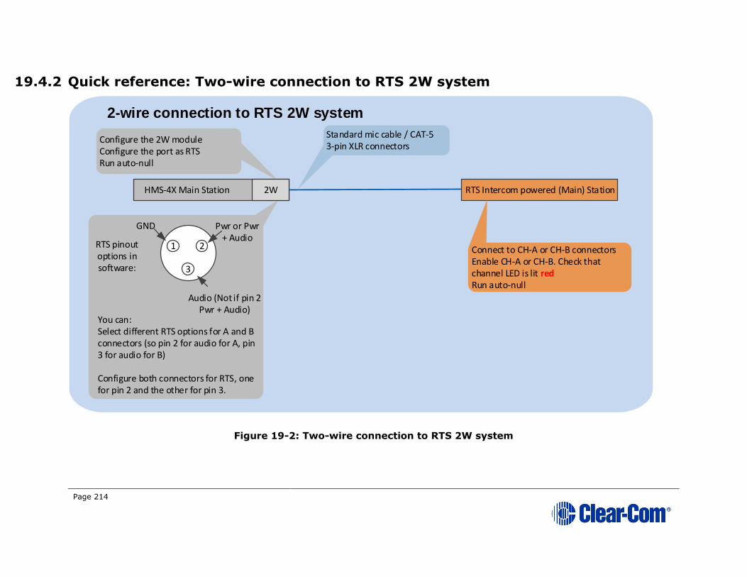
Page 214
19.4.2 Quick reference: Two-wire connection to RTS 2W system
Figure 19-2: Two-wire connection to RTS 2W system
HMS-4X Main Station 2W RTS Intercom powered (Main) Station
Standard mic cable / CAT-53-pin XLR connectors
Configure the 2W moduleConfigure the port as RTSRun auto-null
2W
Connect to CH-A or CH-B connectorsEnable CH-A or CH-B. Check that channel LED is lit redRun auto-null
2-wire connection to RTS 2W system
3
1 2
GND Pwr or Pwr + Audio
Audio (Not if pin 2 Pwr + Audio)
RTS pinout options in software:
You can:Select different RTS options for A and B connectors (so pin 2 for audio for A, pin 3 for audio for B)
Configure both connectors for RTS, one for pin 2 and the other for pin 3.

Page 215
19.4.3 Connecting to an RTS (Telex) intercom station
To connect your HelixNet Partyline system to an RTS intercom station (in this
case,
the 2 Channel MCE325 user station):
1) On the HMS-4X Main Station, configure the Module Settings for the two-wire interface module.
For the full procedure, see 5.6.2 Configuring a Two-wire interface
module.
Ensure that you:
• Configure port(s) for RTS systems. You can select from two
different pinouts when connecting to an RTS two-wire system:
RTS pinout option Description
RTS Audio Pin 2 Pin 2 is used for both power and
audio.
RTS Audio Pin 3 Pin 3 is used for audio (Pin 2 is
used for power only).
Table 19-1: Configuring Module Settings: RTS pinout options
• Run auto-null. Auto-nulling helps to reduce echo while talking
on a two-wire audio system. You must run auto-null every time you change the cabling.
2) Physically connect the HMS-4X Main Station to the RTS intercom station (MCE325). The two Channels of RTS TW intercom must be split prior to
connection with either of the Two-wire module ports. RTS Audio Pin 2
carries the power that is required for the Two-wire module.
Powering the connection:
You must power the connection between the systems using either a dedicated power supply or an RTS power supply.
Connecting to the MCE325 device:
There are three 3-pin XLR connectors on the rear panel of the MCE325
device. In two-wire mode:
• The left and right-hand connectors are used for intercom Channels 1 and 2 input/ output.
• The center connector is used for Channels 3 and 4 input /
output.
• Connect to the selected Channel using standard microphone
cabling.

Page 216
Note: The MCE325 is designed for use with intercom lines with a 200-
Ohm line terminating impedance. A 200 Ohm termination plug is
connected to the center 3-pin XLR connector to prevent Channels
3 and 4 from oscillating when the MCE325 is in two-Channel mode.
3) On the RTS device (in this case, the MCE325), adjust the nulling (if necessary) on the Channel to which the HMS-4X Main Station is
connected.
Nulling helps to reduce echo while talking on a two-wire audio system. A
sidetone nulling trimmer (control) is provided for each of the four
Channels on the device.
To adjust a sidetone nulling trimmer:
a) Turn the speaker switch on (even if an external speaker is not connected). This turns off the internal sidetone trimmer, which controls the sidetone level in headsets.
b) Turn on the microphone. Activate the relevant Talk button and
speak into the microphone.
c) To minimize echo, adjust the sidetone nulling trimmer (located
under the CH1 and CH2 rotary controls).
Note: The default setting for each trimmer is for maximum nulling of the
microphone signal when a 200-ohm resistance terminates the
Channel. However, you may have to adjust the nulling according
to the system configuration.
19.5 Connecting HelixNet Partyline to Tempest®
19.5.1 About Tempest
Note: Tempest is discontinued, and is described here for reference only.
Tempest is a digital wireless intercom system, comprising a base station (Main
Station) and beltpacks. There are two-wire and four-wire versions of Tempest
available. The system operates in either:
• The 2.4GHz ISM band (Tempest 2400 models).
• The 900 MHz ISM band (Tempest 900 models).
Tip: For more information about Tempest, see your Tempest documentation or visit the wireless intercom pages on the Clear-Com website:
http://www.clearcom.com/product/wireless.

Page 217
19.5.2 Quick reference: Two-wire connection to Tempest
Figure 19-3: Two-wire connection to Tempest
HMS-4X Main Station 2W
Power supply
Or
Encore Main Station (MS-20x)
Tempest Basestation
Standard mic cable / CAT-53-pin XLR connectors
Line must be powered (HMS-4X 2W module appears as unpowered beltpack / remote station to Tempest).
Configure the 2W moduleConfigure the port as Clear-ComRun auto-null
2W
Select Clear-Com as the intercom typeSelect the connected channel (A or B)Select 2W modeRun auto-null
Two-wire connection to
Tempest
Page 218
19.5.3 Two-wire connection to Tempest
To connect your HelixNet Partyline system to Tempest, using a two-wire
connection:
1) On the HMS-4X Main Station, configure the Module Settings for the two-wire interface module.
For the full procedure, see 5.6.2 Configuring a Two-wire interface
module.
Note: Check that the Two-wire module is configured for Clear-Com systems (the default) and run Auto-null. Auto-nulling helps to
reduce echo while talking on a two-wire audio system. You must
run auto-null every time you change the cabling.
2) On the Tempest base station:
a) Select Clear-Com as the intercom type, using the slide switch on
the front panel.
b) Configure an intercom Channel for two-wire connection:
i. Select the intercom Channel (A or B), using the CHAN
selection button on the front panel.
ii. Select two-wire connection for the intercom Channel, using
the two-wire / four-wire selection button on the front
panel.
c) Enable Auto-null, using the Tempest menu screens. Enable
Manual Null to remove any residual echo, where desired.
For more detailed information about setting up a two-wire connection on
the Tempest base station, see your Tempest reference manual.
Always set the intercom type before you connect a two-wire intercom system to the Tempest Base station.
Never change the setting while the systems are connected.
Changing the setting while the systems are connected can damage
the Tempest Base station and / or the other system (in this case, HelixNet Partyline).
Page 219
3) Physically connect the HelixNet Partyline and Tempest systems.
Powering the connection:
You must power the connection between the systems using either a
dedicated power supply (such as the PK-7, PS-702, or PS-704), or a
powered Encore Main Station (such as the MS-702 or MS-704).
Tip: For more information about the PK-7 or PS-70x power supply devices from Clear-
Com, see http://www.clearcom.com/product/Partyline/power-supplies
Connecting to Tempest:
You can use standard microphone cable or CAT5 cable types to connect
the HMS-4X Main Station to the Tempest Base station. 3-pin XLR
connectors are located:
• On the HMS-4X Main Station two-wire interface module.
• On the back panel (rear) of the Tempest Base station.
Tip: Tempest provides two-wire input/output gain adjustments, and can be utilized to
either balance the gains between HelixNet and Tempest or connect two-wire system interfaces through a Tempest base station.
4) Adjust the In / Out volume level controls on the Tempest Base station. The In / Out volume levels have the following ranges:
Volume level Range
In -18dB to +4dB
Out -18dB to +4dB
Table 19-2: Tempest Base station In / Out volume levels
For more information, see your Tempest reference manual.
Tip: To optimize audio quality, you may also want to adjust the Audio Settings on
the HMS-4X Main Station. For more information, see 5.2 Configuring the Audio
settings.
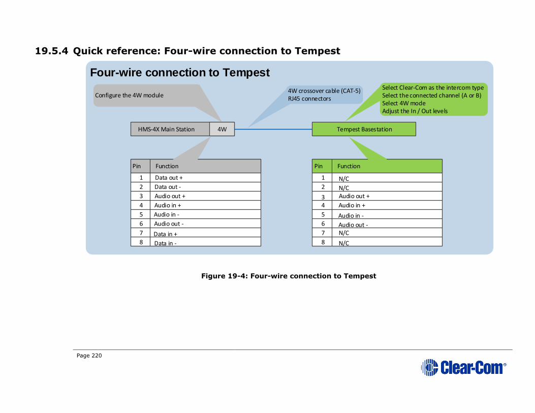
Page 220
19.5.4 Quick reference: Four-wire connection to Tempest
Figure 19-4: Four-wire connection to Tempest
HMS-4X Main Station 2W Tempest Basestation
4W crossover cable (CAT-5)RJ45 connectorsConfigure the 4W module
4W
Select Clear-Com as the intercom typeSelect the connected channel (A or B)Select 4W modeAdjust the In / Out levels
Four-wire connection to Tempest
Pin Function Pin Function
1
5
2
3
4
6
7
8
1
2
34
5
6
7
8
Data out +
Data out -
Audio out +
Audio in +
Audio in -
Audio out -
Data in +
Data in -
N/C
N/C
N/C
N/C
Audio out +
Audio in +
Audio in -
Audio out -
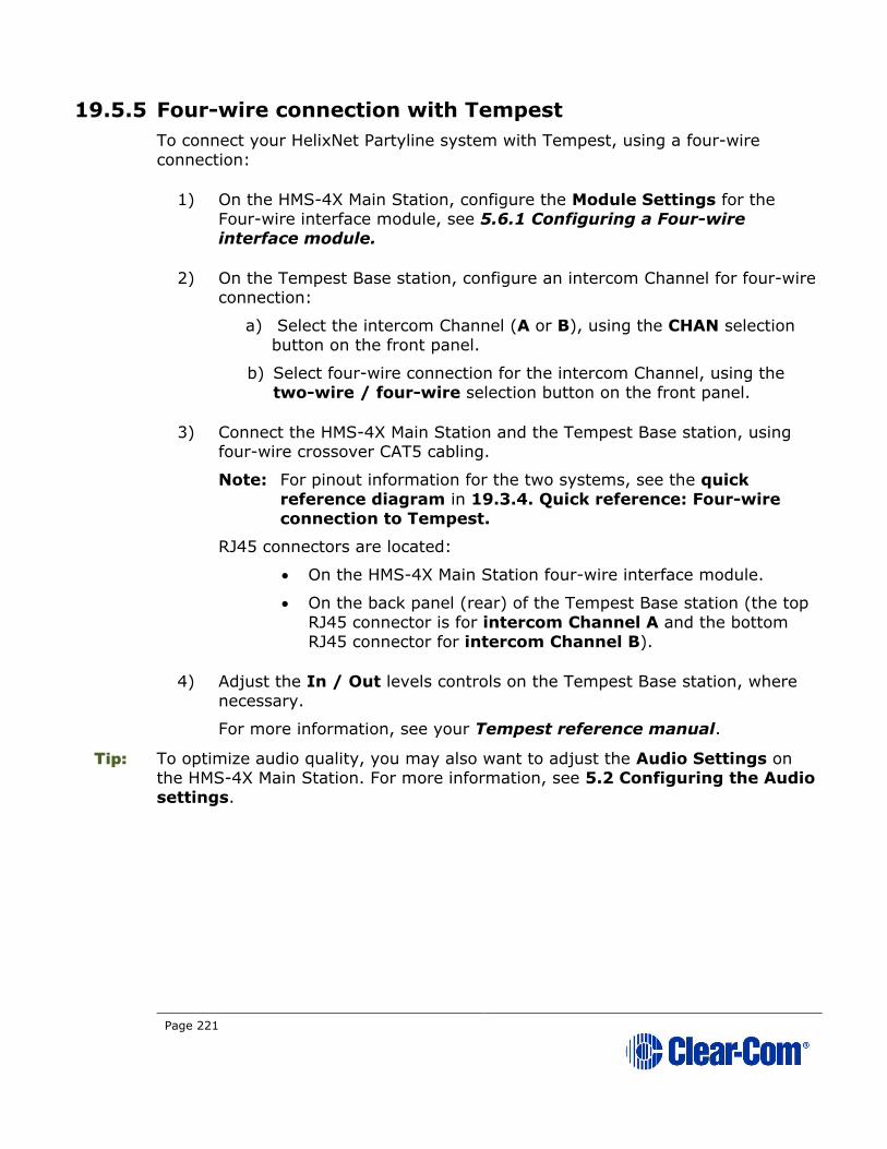
Page 221
19.5.5 Four-wire connection with Tempest
To connect your HelixNet Partyline system with Tempest, using a four-wire
connection:
1) On the HMS-4X Main Station, configure the Module Settings for the Four-wire interface module, see 5.6.1 Configuring a Four-wire
interface module.
2) On the Tempest Base station, configure an intercom Channel for four-wire connection:
a) Select the intercom Channel (A or B), using the CHAN selection
button on the front panel.
b) Select four-wire connection for the intercom Channel, using the
two-wire / four-wire selection button on the front panel.
3) Connect the HMS-4X Main Station and the Tempest Base station, using four-wire crossover CAT5 cabling.
Note: For pinout information for the two systems, see the quick
reference diagram in 19.3.4. Quick reference: Four-wire
connection to Tempest.
RJ45 connectors are located:
• On the HMS-4X Main Station four-wire interface module.
• On the back panel (rear) of the Tempest Base station (the top
RJ45 connector is for intercom Channel A and the bottom
RJ45 connector for intercom Channel B).
4) Adjust the In / Out levels controls on the Tempest Base station, where
necessary.
For more information, see your Tempest reference manual.
Tip: To optimize audio quality, you may also want to adjust the Audio Settings on the HMS-4X Main Station. For more information, see 5.2 Configuring the Audio
settings.

Page 222
19.6 Connecting HelixNet Partyline to CellCom® / FreeSpeak®
19.6.1 About CellCom / FreeSpeak
CellCom / FreeSpeak is a wireless intercom system from Clear-Com, operating
within the license-free 1.92-1.93GHz frequency band. The system is branded as
CellCom in North America and as FreeSpeak in the rest of the world.
CellCom /FreeSpeak combines DECT and wireless auto-roaming technologies to allow users to move freely without losing communication connection. Active
Antennas enable a beltpack-to-base station distance range of up to 3200ft
(1000m).
You can connect up to 20 full-duplex wireless beltpacks (which operate as fully
programmable mobile panels) to one CellCom / FreeSpeak base station (Main Station).
Tip: For more information about CellCom / FreeSpeak, see your CellCom / FreeSpeak documentation or visit the wireless intercom pages on the Clear-Com website:
http://www.clearcom.com/product/wireless.
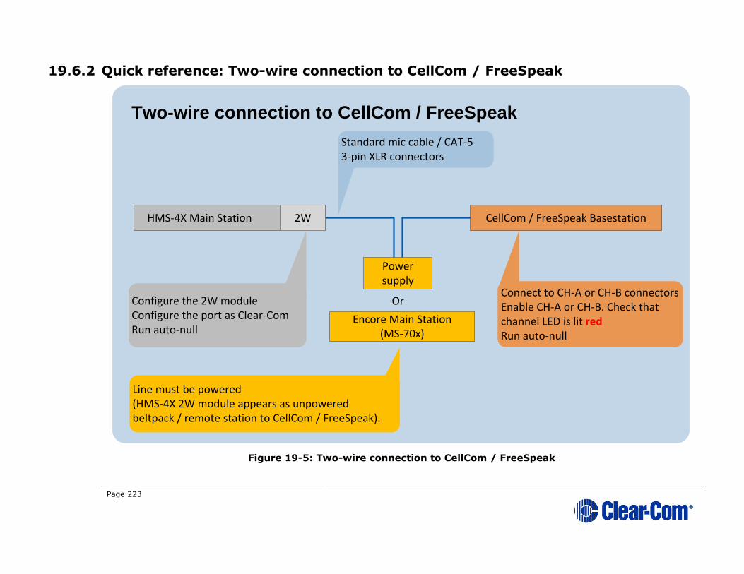
Page 223
19.6.2 Quick reference: Two-wire connection to CellCom / FreeSpeak
Figure 19-5: Two-wire connection to CellCom / FreeSpeak
HMS-4X Main Station 2W
Power supply
Or
Encore Main Station (MS-70x)
CellCom / FreeSpeak Basestation
Standard mic cable / CAT-53-pin XLR connectors
Line must be powered (HMS-4X 2W module appears as unpowered beltpack / remote station to CellCom / FreeSpeak).
Configure the 2W moduleConfigure the port as Clear-ComRun auto-null
2W
Connect to CH-A or CH-B connectorsEnable CH-A or CH-B. Check that channel LED is lit redRun auto-null
Two-wire connection to CellCom / FreeSpeak

Page 224
19.6.3 Two-wire connection to CellCom / FreeSpeak
To connect your HelixNet Partyline system to a CellCom / FreeSpeak base station
(Main Station), using a two-wire connection:
1) On the HMS-4X Main Station, configure the Module Settings for the two-wire interface module. See 5.6.2 Configuring a Two-wire interface
module.
Note: Check that the two-wire module is configured for Clear-Com
systems (the default) and enable Auto-nulling. Auto-nulling helps to reduce echo while talking on a two-wire audio system.
2) There are two Partyline Channels on the CellCom / FreeSpeak base station (CH-A and CH-B). Before connecting the HMS-4X Main Station to the
base station, ensure that the Partyline LED on the front panel for the
selected Channel is off.
Off indicates that the Partyline connection is currently disabled from the
base station.
Note: If the Channel is currently enabled, the Partyline LED is lit red.
3) Physically connect the HMS-4X Main Station to one of the two Partyline Channels on the CellCom / FreeSpeak base station (Main Station).
Powering the connection:
You must power the connection between the systems using either a
dedicated power supply (such as the PK-7, PS-702, or PS-704), or a
powered Encore Main Station (such as the MS-702 or MS-704).
Tip: For more information about the PK-7 or PS-70x power supply devices from Clear-
Com, see http://www.clearcom.com/product/Partyline/power-supplies
Connecting the systems:
Use standard microphone cable to connect the two systems. There are 3-
pin XLR connectors:
• On the HMS-4X Main Station two-wire interface module.
• On the back panel of the CellCom / FreeSpeak Base station.
Two 3-pin XLR connectors, one male, one female, are provided for each of the two Partyline Channels (CH-A and CH-B).
4) On the CellCom / FreeSpeak base station, press Enable on the front panel (located directly beneath the LED for the connected Channel (CH-A or
CH-B)). The LED for the Channel is lit red.
The base station automatically detects and configures the appropriate
power and termination settings when the Channel is enabled. The base

Page 225
station also remembers that the Channel is enabled the next time the
base station is powered up.
5) On the CellCom / FreeSpeak base station, press Enable again and hold. The base station activates auto-nulling on the connected Channel. Auto-
nulling helps to reduce echo while talking on a two-wire audio system.

Page 226
19.6.4 Quick reference: Four-wire connection to CellCom / FreeSpeak
Figure 19-6: Four-wire connection to CellCom / FreeSpeak
HMS-4X Main Station 2W CellCom / FreeSpeak Basestation
4W crossover cable (CAT-5)RJ45 connectorsConfigure the 4W module
4W
Select PORTS > 4-WIRE > CALLS, then select a port / group as the destination for the incoming 4-wire audioAdjust the In / Out levels
Four-wire connection to CellCom / FreeSpeak
Pin Function Pin Function
1
5
2
3
4
6
7
8
1
2
34
5
6
7
8
Data out +
Data out -
Audio out +
Audio in +
Audio in -
Audio out -
Data in +
Data in -
N/C
N/C
N/C
N/C
Audio out +
Audio in +
Audio in -
Audio out -

Page 227
19.6.5 Four-wire connection to CellCom / FreeSpeak
To connect your HelixNet Partyline system to a CellCom / FreeSpeak base station
(Main Station), using a four-wire connection:
1) On the HMS-4X Main Station, configure the Module Settings for the four-wire interface module. For the procedure, see 5.6.1 Configuring a Four-
wire interface module.
2) Connect the HMS-4X Main Station and the CellCom / FreeSpeak base station, using four-wire crossover CAT5 cabling.
Note: For pinout information for the two systems, see the quick
reference diagram in 19.4.4 Quick reference: Four-wire connection to CellCom / FreeSpeak.
RJ45 connectors are located:
• On the HMS-4X Main Station four-wire interface module.
• On the back panel (rear) of the CellCom / FreeSpeak base
station. There are four RJ45 connectors for four-wire connections on the base station.
3) Adjust the In / Out volume levels, using the CellCom / FreeSpeak front panel display. For more information, see your CellCom / FreeSpeak
documentation.
Tip: To optimize audio quality, you may also want to adjust the Audio Settings on the HMS-4X Main Station. For more information, see 5.2 Configuring the Audio
settings.
19.6.6 Four-wire connection to FreeSpeak II Base II
To connect your HelixNet Partyline system to a FreeSpeak II Base II, using a four-
wire connection:
1) From the FS II Base II Station Core Configuration Module (CCM), select Home > Ports > to panel.
2) Connect the HMS-4X Main Station and the FreeSpeak II Base II, using four-wire straight CAT5 cabling.
3) Adjust the audio levels as required.

Page 228
19.7 Connecting HelixNet Partyline to the DX210/DX410
19.7.1 About the DX210
The Clear-Com HME DX210 is a 2 Channel wireless intercom system. The base
station (Main Station) supports up to 15 beltpacks or all-in-one headsets
(headsets operating as beltpacks).
The DX210 supports Clear-Com and RTS cabled two-wire intercom systems, and also has four-wire and auxiliary audio connections.
The DX210 operates in the license-free 2.4GHz band, and has provisions for
spectrum-friendly co-existence with other devices in the same band.
Note: Settings for the DX210 and the DX410 are the same.
Tip: For more information about the DX210, see your DX210 documentation or visit the wireless intercom pages on the Clear-Com website:
http://www.clearcom.com/product/wireless.
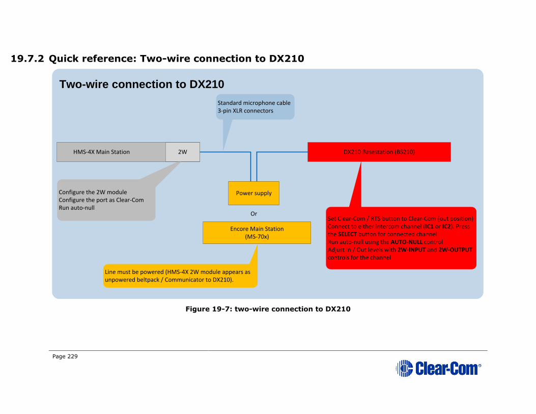
Page 229
19.7.2 Quick reference: Two-wire connection to DX210
Figure 19-7: two-wire connection to DX210
HMS-4X Main Station
Power supply
Or
Encore Main Station (MS-70x)
DX210 Basestation (BS210)
Standard microphone cable3-pin XLR connectors
Line must be powered (HMS-4X 2W module appears as unpowered beltpack / Communicator to DX210).
Configure the 2W moduleConfigure the port as Clear-ComRun auto-null
2W
Set Clear-Com / RTS button to Clear-Com (out position)Connect to either intercom channel (IC1 or IC2). Press the SELECT button for connected channelRun auto-null using the AUTO-NULL controlAdjust In / Out levels with 2W-INPUT and 2W-OUTPUT controls for the channel
Two-wire connection to DX210

Page 230
19.7.3 Two-wire connection to the DX210
To connect your HelixNet Party-line system to the DX210 base station (Main
Station), using a two-wire connection:
1) On the HMS-4X Main Station, configure the Module Settings for the Two-wire interface module. For the procedure, see 5.6.2 Configuring a Two-
wire interface module.
Note: Check that the two-wire module is configured for Clear-Com
systems (the default) and run Auto-null. Auto-nulling helps to reduce echo while talking on a two-wire audio system. You must
run auto-null every time you change the cabling.
2) On the rear panel of the DX210 base station, ensure that the Clear-Com / RTS button is set to Clear-Com mode (the out position).
3) Physically connect the HMS-4X Main Station to one of the two intercom Channels on the DX210 base station (Main Station).
Powering the connection:
You must power the connection between the systems using either a
dedicated power supply (such as the PK-7, PS-702, or PS-704), or a powered Encore Main Station (such as the MS-702 or MS-704).
Tip: For more information about the dedicated power supply devices (PK-7 or PS-70x devices) from Clear-Com, see http://www.clearcom.com/product/Partyline/power-
supplies
Connecting the systems:
Use standard microphone cable to connect the two systems. 3-pin XLR
connectors are located:
• On the HMS-4X Main Station two-wire interface module.
• On the back panel (rear) of the DX210 base station.
Two 3-pin XLR connectors (one male, one female) are provided for each of
the two intercom Channels (IC1 and IC2) on the base station.
4) On the front panel of the DX210 base station, press the SELECT button for the connected intercom Channel (either IC1 or IC2).
The 2-W (two-wire) LED next to the SELECT button is lit green.
Note: If power is not detected at the connector, the 2-W LED is lit red. No audio can be transmitted between the systems. When the
HMS-4X Main Station is powered, power is supplied to the
connection and the 2-W LED is lit green.

Page 231
5) Apply auto-nulling to the connected Channel (either IC1 or IC2) on the DX210 base station. Auto-nulling helps to reduce echo while talking on a
two-wire audio system. To apply auto-nulling:
a) Insert a pen or similar pointed object into the AUTO-NULL hole on
the front panel.
b) Press and hold AUTO-NULL for 2 seconds.
Note: Before applying auto-nulling, ensure that there are no open
microphones on the wired intercom. If users are wearing headsets,
you must notify them of the audio-sweep that precedes the
application of auto-nulling.
6) Adjust the two-wire intercom receive and send levels (in / out levels),
using the 2-W INPUT and 2-W OUTPUT controls for the connected Channel (IC1 or IC2) on the DX210 base station front panel. For more
information, see your DX210 documentation.
Tip: To optimize audio quality, you may also want to adjust the Audio Settings on the HMS-4X Main Station. For more information, see 5.2 Configuring the Audio
settings.

Page 232
19.7.4 Quick reference: Four-wire connection to DX210
Figure 19-8: Four-wire connection to DX210
HMS-4X Main Station 2W DX210 Basestation (BS210)
4W crossover cable (CAT-5)RJ45 connectorsConfigure the 4W module
4W
Connect to either intercom channel (IC1 or IC2). Press the SELECT button for connected channelAdjust In / Out levels with 4W-INPUT and 4W-OUTPUT controls for the channel
Four-wire connection to DX210
Pin Function Pin Function
1
5
2
3
4
6
7
8
1
2
34
5
6
7
8
Data out +
Data out -
Audio out +
Audio in +
Audio in -
Audio out -
Data in +
Data in -
N/C
N/C
N/C
N/C
Audio out +
Audio in +
Audio in -
Audio out -

Page 233
19.7.5 Four-wire connection to the DX
To connect your HelixNet Partyline system with a DX base station, using a four-
wire connection:
1) On the HMS-4X Main Station, configure the Module Settings for the Four-wire interface module. See 5.6.1 Configuring a Four-wire
interface module.
2) Connect the HMS-4X Main Station and the DX base station, using four-wire crossover CAT5 cabling.
Note: For pinout information for the two systems, see the quick
reference diagram in 19.5.4 Quick reference: Four-wire connection to DX210.
RJ45 connectors are located:
• On the HMS-4X Main Station Four-wire interface module.
• On the back panel (rear) of the DX base station.
There is an RJ45 (four-wire) connector for each of the intercom Channels on the DX base station (IC1 and IC2). Connect the systems with a four-
wire crossover CAT5 cable.
3) Adjust the In / Out volume levels, using the DX front panel display. For more information, see your DX documentation.
Tip: To optimize audio quality, you may also want to adjust the Audio Settings on the HMS-4X Main Station. For more information, see 5.2 Configuring the Audio
settings
19.8 Connecting HelixNet Partyline to Eclipse®
19.8.1 About Eclipse
Eclipse is the digital matrix system from Clear-Com. A wide choice of system
frames, system cards and modules enables the unification of multiple intercom systems (digital, analog, wired and wireless) in a single intercoms infrastructure.
Eclipse is configured, managed and maintained using the intuitive Eclipse
Configuration Software (EHX). The Production Maestro® software provides a
centralized routing tool, to assist with four-wire configurations. Logic Maestro is a
graphical programming tool for EHX, simplifying the design and programming of
complex logical functions.
The following procedures reference the following Eclipse devices:
• The Eclipse or Eclipse-HX system frame. For example, the Eclipse
Median is a 6RU frame that houses 2 CPU and 7 matrix slots with 8 built-
in interface module slots.

Page 234
• The CCI-22 interface module. The CCI-22 is the two-wire party-line
interface (Clear-Com and / or RTS) to Eclipse. EHX views a direct, four-
wire HelixNet Party-line connection with the system frame as a ‘virtual’
CCI-22 connection.
Tip: For more information about Eclipse, see your Eclipse / EHX documentation or visit the digital matrix pages on the Clear-Com website:
http://www.clearcom.com/product/digital-matrix.

Page 235
19.8.2 Quick reference: Two-wire connection to Eclipse
Figure 19-9: Two-wire connection to an Eclipse Matrix
Example connection: 3-pin XLR to DB9M on CCI-22
HMS-4X Main Station 2W
Power supply
Or
Encore Main Station (MS-70x)
Line must be powered (CCI-22 module views HMS-4X Main Station as an unpowered beltpack / remote station)
2W EclipseMedian
CCI-22
3-pin XLR connector to DB9 connector
2-wire connection to Eclipse
1 2
3
5
3
2
1
48
9
7
6
To chassis ground on frame
GND
Audio
Pwr
Optional Clear-Com / RTS external switch (on CCI-22)
0.01 uF
Configure the 2W moduleConfigure the port as Clear-ComRun auto-null
Adjust nullingAdjust In / Out levels (if necessary)
There is a cat5 cable that is a patch from one panel to another on the median frame.

Page 236
19.8.3 Two-wire connection to an Eclipse or Eclipse-HX system frame
To connect your HelixNet Partyline system to an Eclipse or Eclipse-HX System,
using a two-wire connection:
1) On the HMS-4X Main Station, configure the Module Settings for the Two-wire interface module. For the procedure, see 5.6.2 Configuring a Two-
wire interface module.
Note: Check that the two-wire module is configured for Clear-Com
systems (the default) and run Auto-null. Auto-nulling helps to
reduce echo while talking on a two-wire audio system. You must
run auto-null every time you change the cabling.
2) Physically connect the HMS-4X Main Station (HLI-2W2) to the CCI-22 dual-Channel party-line interface module.
The CCI-22 may be fitted:
• Directly to an Eclipse or Eclipse-HX System.
• An interface frame (such as the IMF-3 or IMF-102), connected
to the Eclipse matrix.
Tip: For more information about installing and using the CCI-22, see the CCI-22 Manual, or go to: http://www.clearcom.com/product/digital-matrix/interface-
modules/cci-22
Powering the connection:
You must power the connection between the HMS-4X Main Station (HLI-
2W2) and the CCI-22 using either a dedicated power supply (such as the
PK-7, PS-702, or PS-704), or a powered Encore Main Station (such as the
MS-702 or MS-704).
Tip: For more information about the PK-7 or PS-70x power supply devices from Clear-Com, see http://www.clearcom.com/product/Partyline/power-supplies
Connecting the systems:
There are two parallel DB-9M Interface I/O connectors on the CCI-22. The two-wire module on the HMS-4X Main Station features two 3-pin XLR
connectors. For more information about wiring the connection, see:
• 19.6.2 Quick reference: Two-wire connection to Eclipse.
• The CCI-22 Manual.
3) Apply nulling to the connected Channel on the CCI-22. To null the Channel:
a) Insert the accessory earphone into the front-panel Test jack. A test tone, for all frequencies, is produced every 0.5s.
Page 237
b) While listening to the test tone, adjust the R (Resistance) control
until the tone is at a minimum.
c) Repeat Step b. for the L (Inductance) and C (Capacitance) controls.
These controls compensate for each component of the line’s
impedance, providing the best possible null.
Because the R, L and C controls interact, you may have to adjust these
controls several times to minimize the test tone / achieve a deep null.
Note: The null circuit on the CCI-22 is effective on line lengths between
0 - 4000 feet (1200m) with impedances in the range of 120 to 350
ohms. Nulling can reduce local audio in the received signal by < 30 dB over the 200 Hz - 8 kHz frequency range.
Tip: For more information on the CCI-22 nulling circuit, see the CCI-22 Manual.
4) If necessary, adjust the In / Out level controls on the CCI-22 (Send and Recv, located on the front panel next to the R, L and C nulling controls).
Note: The Send level control affects the level of the audio signals from
the
Eclipse Matrix to the external party-line, and the Recv control affects the
level of the audio from the party-line into the matrix. The Send and
Receive controls have a range of ± 13 dB.
Tip: For more information about managing the HelixNet to Eclipse connection in EHX, see your EHX documentation (including Help).

Page 238
19.8.4 Quick reference: Four-wire connection to Eclipse
Figure 19-10: Four-wire connection to Eclipse Matrix
HMS-4X Main Station 2W
Configure the 4W module
4W
RJ45 connectors located on rear panel of MVX-A16, the 16 port audio and data card set
Four-wire connection to Eclipse
EclipseMedian
MVX-A16
1:1 direct CAT-5 connectionRJ45 connectors
No pinout compatibility issues (no crossover cable required)

Page 239
19.8.5 Four-wire connection to Eclipse
To connect your HelixNet Partyline system to an Eclipse or Eclipse-HX System,
using a four-wire connection:
1) On the HMS-4X Main Station, configure the Module Settings for the four-wire interface module. For the procedure, see 5.6.1 Configuring a Four-wire interface module.
2) Connect the HMS-4X Main Station directly to the MVX-A16 card (the 16 port audio and data card set) with standard CAT5 cable.
Note: For pinout information for the two systems, see the quick
reference diagram in 19.6.4 Quick reference: Four-wire
connection to Eclipse.
RJ45 connectors are located:
• On the HMS-4X Main Station four-wire interface module.
• On the rear panel of the MVX-A16 card.
Tip: To optimize audio quality, you may want to adjust the Audio Settings on the HMS-4X Main Station. For more information, see 5.2 Configuring the Audio
settings
Tip: For more information about managing the HelixNet to Eclipse connection in EHX, see your EHX documentation (including EHX Help).
19.9 Connecting HelixNet Partyline to two-way radio
systems
Two-way radio systems (also known as walkie-talkies) are widely used for wireless communication where quick deployment is a required.
HelixNet can interface to a two-way radio system audio along with transmit key
control.
The following examples show how you can setup HelixNet to activate a relay on a
Main Station or a Remote Station every time someone activates a Talk key on the selected Partyline Channel.
Note: HelixNet provides and expects 4W audio at line level (0dBu).

Page 240
19.9.1 Quick Reference: four-wire and control connection to radio system
Figure 19-11 Four-wire and control connection to radio system
HMS-4X Main Station 2W Radio basestation
4W RJ45 connector
Configure the 4W module
4W
Four-wire connection to radio system
Pin Function
1
5
2
3
4
6
78
Data out +
Data out -
Audio out +
Audio in +
Audio in -
Audio out -
Data in +
Data in -
Control I/O D-type connector
Pin Function Pin Function
12
3
4
5
6
78
9
10
11
12
13
1415
16
17
18
19
2021
22
23
24
25
Relay 1 NC
Relay 1 NO
Relay 2 Pole
Relay 3 NC
Relay 3 NO
Relay 4 Pole
GNDGND
Opto 1+
Opto 2+
Opto 3+
Opto 4+
Relay 1 Pole
Relay 2 NC
Relay 2 NO
Relay 3 Pole
Relay 4 NC
Relay 4 NO
+5V
+5V
Opto 1-
Opto 2-
Opto 3-
Opto 4-
Page 241
19.9.2 Four-wire and control connection to radio system
To connect the HelixNet Partyline to a radio system using four-wire:
1) In the Modules Settings menu, select Slot n/Port A/B 4W > Channel Assign > Channel # to assign the 4W port to a Channel, for example
Channel A.
2) In the Modules Settings menu, select Slot n/Port A/B 4W > GPO
Trigger > Disable to set GPO Trigger to Disable for that 4W port.
3) In the Channels menu, select Channel # > GPO on Talk > Relay # to
select a Relay.
4) Connect the 4W audio and the configured Relay to the radio base station.
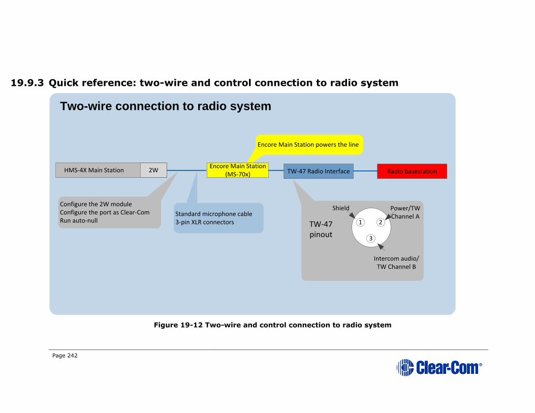
Page 242
19.9.3 Quick reference: two-wire and control connection to radio system
Figure 19-12 Two-wire and control connection to radio system
HMS-4X Main Station 2WEncore Main Station
(MS-70x)
Configure the 2W moduleConfigure the port as Clear-ComRun auto-null
2W
Two-wire connection to radio system
Standard microphone cable3-pin XLR connectors
Encore Main Station powers the line
TW-47 Radio Interface Radio basestation
3
1 2
Shield Power/TW Channel A
Intercom audio/TW Channel B
TW-47 pinout
Page 243
19.9.4 Two-wire and control connection to radio system
The two-wire connection uses a TW-47 radio interface. Because this has no power
supply, you must use an Encore Main Station to supply power. You can also use
an alternative source of power, such as a PK-7, PS-702 or PS-704.
The diagram in Figure 19-12 shows a system using an Encore Main Station.
To connect the HelixNet Partyline to a radio system using two-wire:
1) Connect the HelixNet Partyline to the Encore Main Station. For details, see 19.1 Connecting HelixNet Partyline to Encore®.
2) In the Modules Settings menu, select Slot n/Port A/B 2W > Channel Assign > Channel # to assign the 2W port to a Channel, for example
Channel A.
3) Connect the Encore Main Station to the TW-47 radio interface.
4) Connect the TW-47 radio interface to the radio base station.
5) To trigger the PTT on the radio base, press the CALL button on the HelixNet channel.

Page 244
19.9.5 Quick reference: Remote Station connection to radio system
Figure 19-13 Main Station connection to radio system
HMS-4X Main Station 2W Radio basestation
Configure the 4W module
4W
Four-wire connection to radio system
Control I/O D-type connector
Pin Function Pin Function
12
3
4
5
6
78
9
10
11
12
13
1415
16
17
18
19
2021
22
23
24
25
Relay 1 NC
Relay 1 NO
Relay 2 Pole
Relay 3 NC
Relay 3 NO
Relay 4 Pole
GNDGND
Opto 1+
Opto 2+
Opto 3+
Opto 4+
Relay 1 Pole
Relay 2 NC
Relay 2 NO
Relay 3 Pole
Relay 4 NC
Relay 4 NO
+5V
+5V
Opto 1-
Opto 2-
Opto 3-
Opto 4-

Page 245
To connect the HelixNet Remote Station to a radio system using four-wire:
1) In the Audio Settings menu, select PGM/Audio In > GPO Trigger > Disable.
2) In the Audio Settings menu, select SA/Audio Out Mode > Channel Assign.
3) Assign the SA/Audio Out to a Channel.
4) In the Channel configuration select the Remote Station Program under the Program Listen menu.
5) In the Channels menu, select Channel # > GPO on Talk > Relay 1.
6) Connect the audio and the Relay to the radio base station.
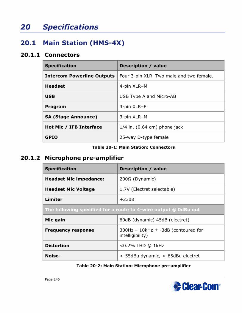
Page 246
20 Specifications
20.1 Main Station (HMS-4X)
20.1.1 Connectors
Specification Description / value
Intercom Powerline Outputs Four 3-pin XLR. Two male and two female.
Headset 4-pin XLR–M
USB USB Type A and Micro-AB
Program 3-pin XLR–F
SA (Stage Announce) 3-pin XLR–M
Hot Mic / IFB Interface 1/4 in. (0.64 cm) phone jack
GPIO 25-way D-type female
Table 20-1: Main Station: Connectors
20.1.2 Microphone pre-amplifier
Specification Description / value
Headset Mic impedance: 200Ω (Dynamic)
Headset Mic Voltage 1.7V (Electret selectable)
Limiter +23dB
The following specified for a route to 4-wire output @ 0dBu out
Mic gain 60dB (dynamic) 45dB (electret)
Frequency response 300Hz – 10kHz ± -3dB (contoured for
intelligibility)
Distortion <0.2% THD @ 1kHz
Noise- <-55dBu dynamic, <-65dBu electret
Table 20-2: Main Station: Microphone pre-amplifier
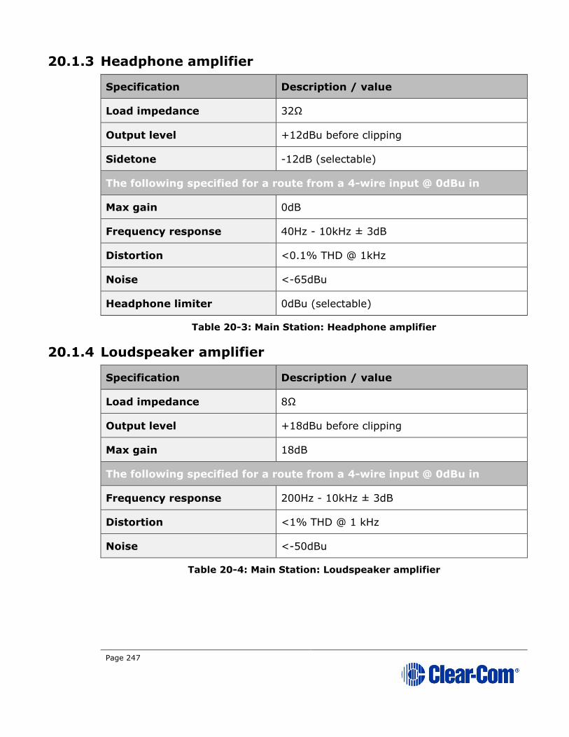
Page 247
20.1.3 Headphone amplifier
Specification Description / value
Load impedance 32Ω
Output level +12dBu before clipping
Sidetone -12dB (selectable)
The following specified for a route from a 4-wire input @ 0dBu in
Max gain 0dB
Frequency response 40Hz - 10kHz ± 3dB
Distortion <0.1% THD @ 1kHz
Noise <-65dBu
Headphone limiter 0dBu (selectable)
Table 20-3: Main Station: Headphone amplifier
20.1.4 Loudspeaker amplifier
Specification Description / value
Load impedance 8Ω
Output level +18dBu before clipping
Max gain 18dB
The following specified for a route from a 4-wire input @ 0dBu in
Frequency response 200Hz - 10kHz ± 3dB
Distortion <1% THD @ 1 kHz
Noise <-50dBu
Table 20-4: Main Station: Loudspeaker amplifier

Page 248
20.1.5 Program line input and Four-wire option module inputs
Specification Description / value
Maximum level before
clipping
18dBu
Nominal input level 0dBu (selectable)
Input impedance >= 10KΩ
The following specified for a route to 4-wire output @ 0dBu out
Frequency response 20Hz - 10kHz ± 3dB
Distortion <0.2% THD @ 1kHz
Noise <-65dBu
Table 20-5: Main Station: Program line input and four-wire option module inputs
20.1.6 Four-wire module outputs
Specification Description / value
Maximum level before
clipping
18dBu
Nominal input level 0dBu (selectable)
Input impedance <= 100Ω
Table 20-6: Main Station: Four-wire module outputs
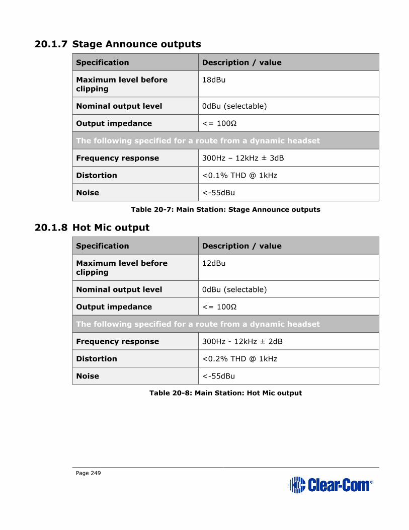
Page 249
20.1.7 Stage Announce outputs
Specification Description / value
Maximum level before
clipping
18dBu
Nominal output level 0dBu (selectable)
Output impedance <= 100Ω
The following specified for a route from a dynamic headset
Frequency response 300Hz – 12kHz ± 3dB
Distortion <0.1% THD @ 1kHz
Noise <-55dBu
Table 20-7: Main Station: Stage Announce outputs
20.1.8 Hot Mic output
Specification Description / value
Maximum level before
clipping
12dBu
Nominal output level 0dBu (selectable)
Output impedance <= 100Ω
The following specified for a route from a dynamic headset
Frequency response 300Hz - 12kHz ± 2dB
Distortion <0.2% THD @ 1kHz
Noise <-55dBu
Table 20-8: Main Station: Hot Mic output

Page 250
20.1.9 Helix Digital Partyline
Specification Description / value
Maximum level before
clipping
6dBu
Nominal input level -18dBu (C-C) -12dBu (RTS)
Input impedance >= 10KΩ bridging
The following specified for a circuit to a 4-wire output @0dBu in:
Frequency response 100Hz - 10 kHz ± 3dB
Distortion <0.2% THD @ 1kHz
Noise <-55dBu
The following specified for a circuit from a 2-wire input @0dBu out:
Frequency response 40Hz - 10kHz ± 3dB
Distortion <0.2% THD @ 1kHz
Noise <-55dBu
Auto-nulling and echo
cancellation
Yes
RTS / Clear-Com selectable Yes
Termination External
Power 30V external
Table 20-9: Main Station: Partyline
20.1.10 Ethernet
Specification Description / value
Fast Ethernet standard 100BaseT only, Auto MDIX
Table 20-10: Main Station: Ethernet
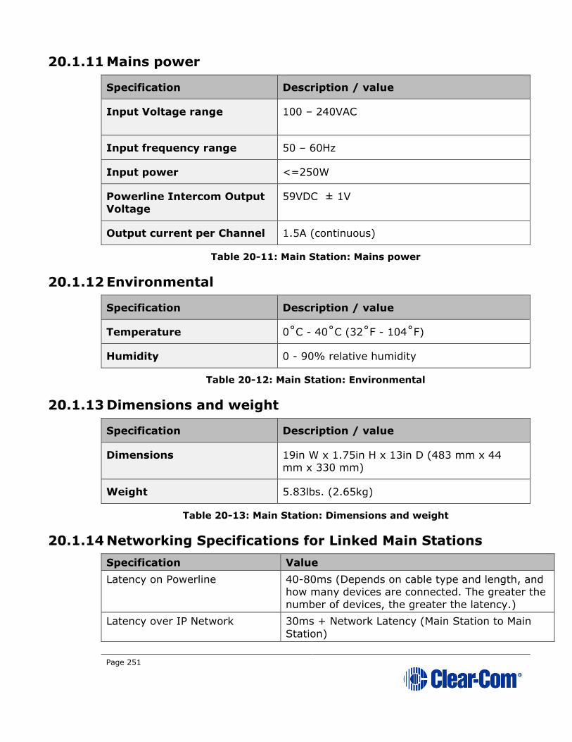
Page 251
20.1.11 Mains power
Specification Description / value
Input Voltage range 100 – 240VAC
Input frequency range 50 – 60Hz
Input power <=250W
Powerline Intercom Output
Voltage
59VDC ± 1V
Output current per Channel 1.5A (continuous)
Table 20-11: Main Station: Mains power
20.1.12 Environmental
Specification Description / value
Temperature 0˚C - 40˚C (32˚F - 104˚F)
Humidity 0 - 90% relative humidity
Table 20-12: Main Station: Environmental
20.1.13 Dimensions and weight
Specification Description / value
Dimensions 19in W x 1.75in H x 13in D (483 mm x 44 mm x 330 mm)
Weight 5.83lbs. (2.65kg)
Table 20-13: Main Station: Dimensions and weight
20.1.14 Networking Specifications for Linked Main Stations
Specification Value
Latency on Powerline 40-80ms (Depends on cable type and length, and how many devices are connected. The greater the
number of devices, the greater the latency.)
Latency over IP Network 30ms + Network Latency (Main Station to Main
Station)

Page 252
Bandwidth used 300 kbps per active Talker, for a maximum of one
talker per device in the system.
Each beltpack and Speaker Station counts as one
device.
Each Main Station and Remote Station counts as
two devices.
Each HLI-2W2 or HLI-4W2 counts as two devices.
IP version IPv4
Table 20-14 Networking specifications
20.2 Two-wire module (HLI-2W2)
20.2.1 Connectors
Specification Description / value
Intercom line (2) 3-Pin XLR-F
Table 20-15: two-wire module: Connectors
20.2.2 Dimensions and weight
Specification Description / value
Dimensions 7.05 in. H x 2.24 in. W x 1.54 in. D (179 x 57
x39 mm)
Weight 13oz. (0.35kg)
Table 20-16: Two-wire module: Dimensions and weight
20.2.3 Power requirements (external)
Specification Description / value
Per Channel 0.025mA/Channel
DC Voltage range 20 – 30Volts
Table 20-17: Two-wire module: Power requirements
20.2.4 Environmental
Specification Description / value

Page 253
Temperature 0˚C - 40˚C (32˚F - 104˚F)
Humidity 0 - 90% relative humidity
Table 20-18: Two-wire module: Environmental
20.3 Four-wire module (HLI-4W2)
20.3.1 Connectors
Specification Description / value
Intercom line (2) RJ45 (etherCON)
Table 20-19: Four-wire module: Connectors
20.3.2 Dimensions and weight
Specification Description / value
Dimensions 7.05 in. H x 2.24 in. W x 1.54 in. D (179 x 57
x39 mm)
Weight 13oz. (0.35kg)
Table 20-20: four-wire module: Dimensions and weight
20.3.3 Environmental
Specification Description / value
Temperature 0˚C - 40˚C (32˚F - 104˚F)
Humidity 0 - 90% relative humidity
Table 20-21: four-wire module: Environmental
20.4 Remote Station (HRM-4X)
20.4.1 Connectors
Specification Description / value
Intercom Powerline Outputs Two 3-pin XLR. One male and one female.
Headset 4-pin XLR–M

Page 254
Specification Description / value
USB USB Type A
Program 3-pin XLR–F
SA (Stage Announce) 3-pin XLR–M
Hot Mic / IFB Interface 1/4 in. (0.64 cm) phone jack
Control and audio
input/output
9-pin D-type
Table 20-22: Remote Station: Connectors
20.4.2 Microphone pre-amplifier
Specification Description / value
Headset Mic impedance: 200Ω (Dynamic)
Headset Mic Voltage 1.7V (Electret selectable)
Limiter +23dB
The following specified for a route to 4-wire output @ 0dBu out
Mic gain 60dB (dynamic) 45dB (electret)
Frequency response 300Hz – 10kHz + / -3dB (contoured for intelligibility)
Distortion <0.2% THD @ 1 kHz
Noise- <-55dBu dynamic, <-65dBu electret
Table 20-23: Remote Station: Microphone pre-amplifier
20.4.3 Headphone amplifier
Specification Description / value
Load impedance 32Ω
Output level +12dBu before clipping
Sidetone -12dB (selectable)
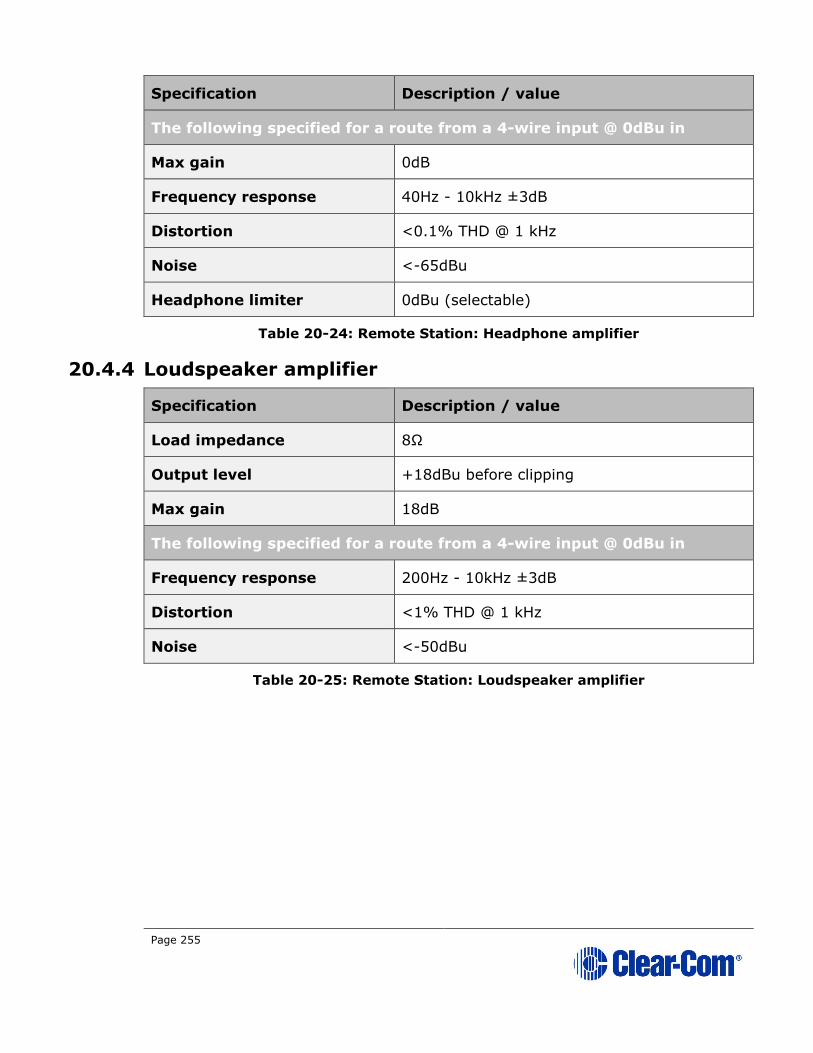
Page 255
Specification Description / value
The following specified for a route from a 4-wire input @ 0dBu in
Max gain 0dB
Frequency response 40Hz - 10kHz ±3dB
Distortion <0.1% THD @ 1 kHz
Noise <-65dBu
Headphone limiter 0dBu (selectable)
Table 20-24: Remote Station: Headphone amplifier
20.4.4 Loudspeaker amplifier
Specification Description / value
Load impedance 8Ω
Output level +18dBu before clipping
Max gain 18dB
The following specified for a route from a 4-wire input @ 0dBu in
Frequency response 200Hz - 10kHz ±3dB
Distortion <1% THD @ 1 kHz
Noise <-50dBu
Table 20-25: Remote Station: Loudspeaker amplifier

Page 256
20.4.5 Program line input and four-wire option module inputs
Specification Description / value
Maximum level before
clipping
18dBu
Nominal input level 0dBu(selectable)
Input impedance >= 10 KΩ
The following specified for a route to 4-wire output @ 0dBu out
Frequency response 20Hz - 10kHz ±3dB
Distortion <0.2% THD @ 1kHz
Noise <-65dBu
Table 20-26: Remote Station: Program line input and four-wire option module
inputs
20.4.6 Four-wire module outputs
Specification Description / value
Maximum level before
clipping
18dBu
Nominal input level 0dBu(selectable)
Input impedance <= 100Ω
Table 20-27: Remote Station: Four-wire module outputs
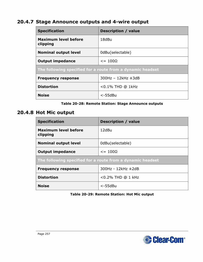
Page 257
20.4.7 Stage Announce outputs and 4-wire output
Specification Description / value
Maximum level before
clipping
18dBu
Nominal output level 0dBu(selectable)
Output impedance <= 100Ω
The following specified for a route from a dynamic headset
Frequency response 300Hz – 12kHz ±3dB
Distortion <0.1% THD @ 1kHz
Noise <-55dBu
Table 20-28: Remote Station: Stage Announce outputs
20.4.8 Hot Mic output
Specification Description / value
Maximum level before
clipping
12dBu
Nominal output level 0dBu(selectable)
Output impedance <= 100Ω
The following specified for a route from a dynamic headset
Frequency response 300Hz - 12kHz ±2dB
Distortion <0.2% THD @ 1 kHz
Noise <-55dBu
Table 20-29: Remote Station: Hot Mic output
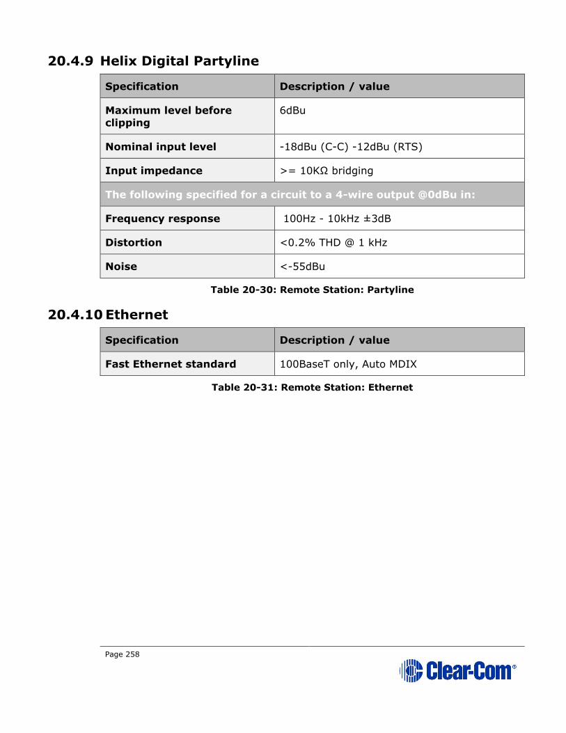
Page 258
20.4.9 Helix Digital Partyline
Specification Description / value
Maximum level before
clipping
6dBu
Nominal input level -18dBu (C-C) -12dBu (RTS)
Input impedance >= 10KΩ bridging
The following specified for a circuit to a 4-wire output @0dBu in:
Frequency response 100Hz - 10kHz ±3dB
Distortion <0.2% THD @ 1 kHz
Noise <-55dBu
Table 20-30: Remote Station: Partyline
20.4.10 Ethernet
Specification Description / value
Fast Ethernet standard 100BaseT only, Auto MDIX
Table 20-31: Remote Station: Ethernet
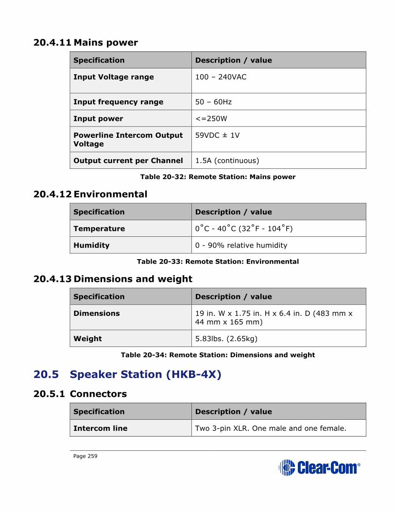
Page 259
20.4.11 Mains power
Specification Description / value
Input Voltage range 100 – 240VAC
Input frequency range 50 – 60Hz
Input power <=250W
Powerline Intercom Output
Voltage
59VDC ± 1V
Output current per Channel 1.5A (continuous)
Table 20-32: Remote Station: Mains power
20.4.12 Environmental
Specification Description / value
Temperature 0˚C - 40˚C (32˚F - 104˚F)
Humidity 0 - 90% relative humidity
Table 20-33: Remote Station: Environmental
20.4.13 Dimensions and weight
Specification Description / value
Dimensions 19 in. W x 1.75 in. H x 6.4 in. D (483 mm x 44 mm x 165 mm)
Weight 5.83lbs. (2.65kg)
Table 20-34: Remote Station: Dimensions and weight
20.5 Speaker Station (HKB-4X)
20.5.1 Connectors
Specification Description / value
Intercom line Two 3-pin XLR. One male and one female.

Page 260
Specification Description / value
Screw terminals
Headset 4-pin XLR–M
Table 20-35: Speaker Station: Connectors
20.5.2 Microphone pre-amplifier
Specification Description / value
Headset Mic impedance: 200Ω (Dynamic)
Headset Mic Voltage 1.7V (Electret selectable)
Limiter +23dB
The following specified for a route to 4-wire output @ 0dBu out:
Mic gain 60dB (dynamic) 45dB (electret)
Frequency response 300Hz – 10kHz + / -3dB (contoured for
intelligibility)
Distortion <0.2% THD @ 1kHz
Noise- <-55dBu dynamic, <-65dBu electret
Table 20-36: Speaker Station: Microphone pre-amplifier
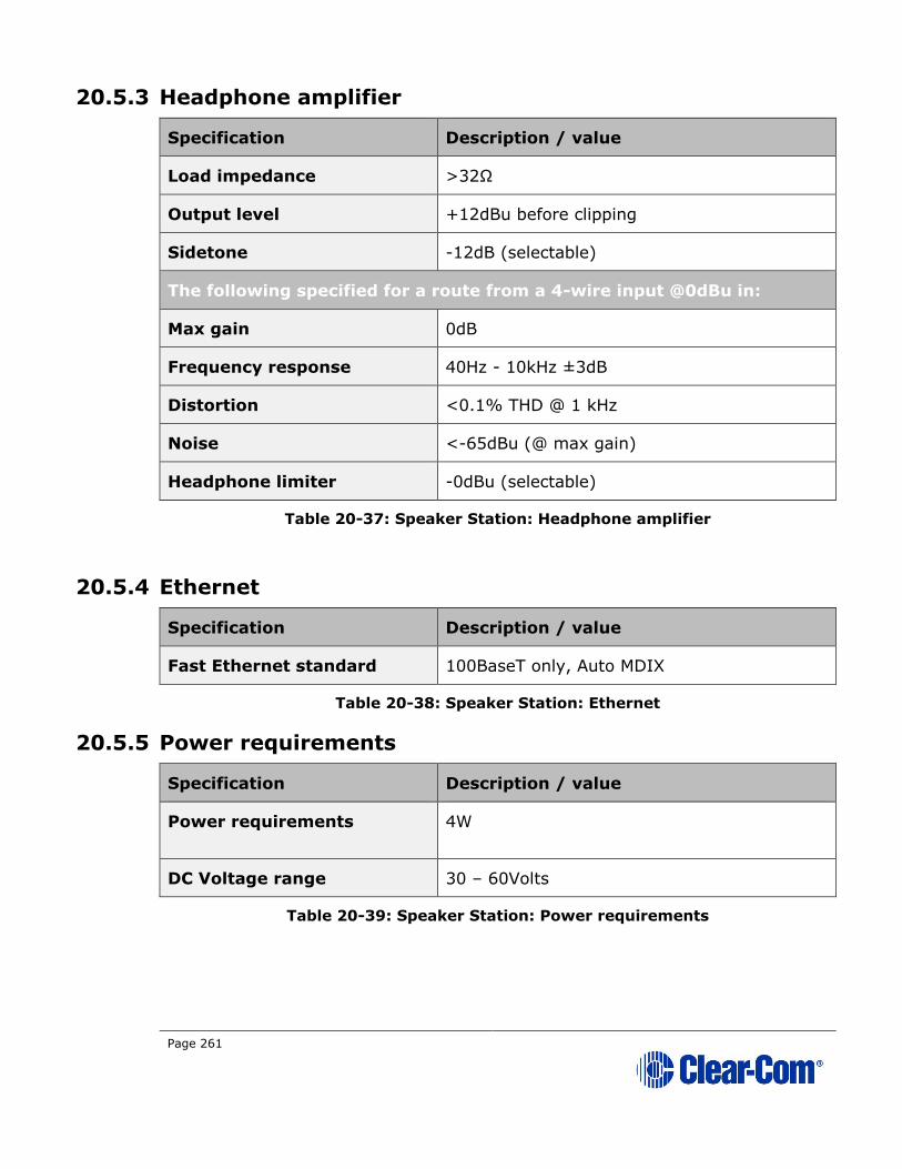
Page 261
20.5.3 Headphone amplifier
Specification Description / value
Load impedance >32Ω
Output level +12dBu before clipping
Sidetone -12dB (selectable)
The following specified for a route from a 4-wire input @0dBu in:
Max gain 0dB
Frequency response 40Hz - 10kHz ±3dB
Distortion <0.1% THD @ 1 kHz
Noise <-65dBu (@ max gain)
Headphone limiter -0dBu (selectable)
Table 20-37: Speaker Station: Headphone amplifier
20.5.4 Ethernet
Specification Description / value
Fast Ethernet standard 100BaseT only, Auto MDIX
Table 20-38: Speaker Station: Ethernet
20.5.5 Power requirements
Specification Description / value
Power requirements 4W
DC Voltage range 30 – 60Volts
Table 20-39: Speaker Station: Power requirements
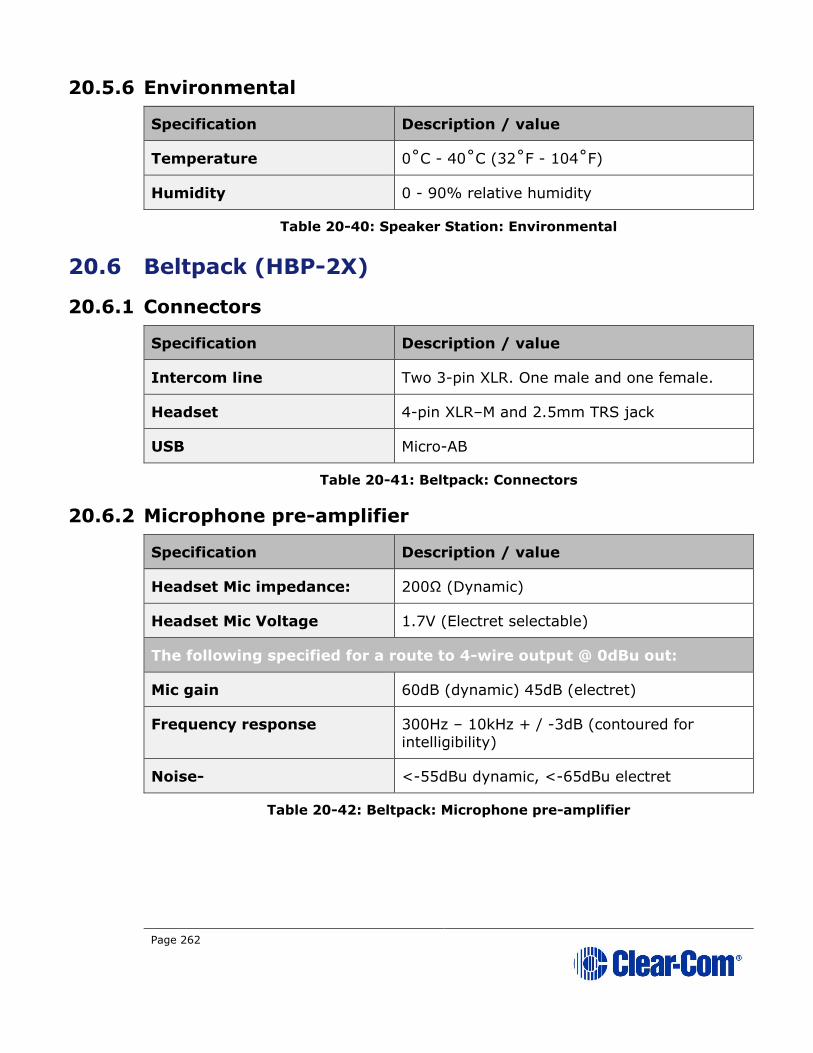
Page 262
20.5.6 Environmental
Specification Description / value
Temperature 0˚C - 40˚C (32˚F - 104˚F)
Humidity 0 - 90% relative humidity
Table 20-40: Speaker Station: Environmental
20.6 Beltpack (HBP-2X)
20.6.1 Connectors
Specification Description / value
Intercom line Two 3-pin XLR. One male and one female.
Headset 4-pin XLR–M and 2.5mm TRS jack
USB Micro-AB
Table 20-41: Beltpack: Connectors
20.6.2 Microphone pre-amplifier
Specification Description / value
Headset Mic impedance: 200Ω (Dynamic)
Headset Mic Voltage 1.7V (Electret selectable)
The following specified for a route to 4-wire output @ 0dBu out:
Mic gain 60dB (dynamic) 45dB (electret)
Frequency response 300Hz – 10kHz + / -3dB (contoured for
intelligibility)
Noise- <-55dBu dynamic, <-65dBu electret
Table 20-42: Beltpack: Microphone pre-amplifier

Page 263
20.6.3 Headphone amplifier
Specification Description / value
Load impedance >32 Ω
Output level +12dBu before clipping
Sidetone -12dB (selectable)
The following specified for a route from a 4-wire input @0dBu in:
Max gain 0dB
Frequency response 40Hz - 10kHz ±3dB
Noise <-65dBu (@ max gain)
Headphone limiter -0dBu (selectable)
Table 20-43: Beltpack: Headphone amplifier
20.6.4 Environmental
Specification Description / value
Temperature 0˚C - 40˚C (32˚F - 104˚F)
Humidity 0 - 90% relative humidity
Table 20-44: Beltpack: Environmental

Page 264
20.7 Beltpack (HXII-BP-X4)
20.7.1 Connectors
Specification Description / value
Intercom line 3-pin XLR (female).
etherCon connector LAN/PoE connector
Headset 4-pin XLR–M
USB Micro-AB
Table 20-45: Beltpack: Connectors
20.7.2 Microphone pre-amplifier
Specification Description / value
Headset Mic impedance: 200Ω (Dynamic)
Headset Mic Voltage 1.7V (Electret selectable)
The following specified for a route to 4-wire output @ 0dBu out:
Mic gain 60dB (dynamic) 45dB (electret)
Frequency response 300Hz – 10kHz + / -3dB (contoured for
intelligibility)
Noise- <-55dBu dynamic, <-65dBu electret
Table 20-46: Beltpack: Microphone pre-amplifier
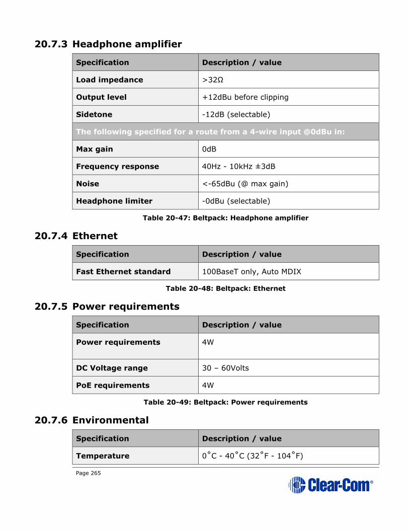
Page 265
20.7.3 Headphone amplifier
Specification Description / value
Load impedance >32Ω
Output level +12dBu before clipping
Sidetone -12dB (selectable)
The following specified for a route from a 4-wire input @0dBu in:
Max gain 0dB
Frequency response 40Hz - 10kHz ±3dB
Noise <-65dBu (@ max gain)
Headphone limiter -0dBu (selectable)
Table 20-47: Beltpack: Headphone amplifier
20.7.4 Ethernet
Specification Description / value
Fast Ethernet standard 100BaseT only, Auto MDIX
Table 20-48: Beltpack: Ethernet
20.7.5 Power requirements
Specification Description / value
Power requirements 4W
DC Voltage range 30 – 60Volts
PoE requirements 4W
Table 20-49: Beltpack: Power requirements
20.7.6 Environmental
Specification Description / value
Temperature 0˚C - 40˚C (32˚F - 104˚F)

Page 266
Humidity 0 - 90% relative humidity
Table 20-50: Beltpack: Environmental

Page 267
21 Glossary
Channel Any audio routed through the HelixNet system must be
configured into a Channel. Channels operate as virtual
Partylines, which means that audio sources assigned to a Channel will be able to talk and listen to all other sources
assigned to that Channel. In order for an audio source on
one device to talk to an audio source on another device, the
two Keysets must be brought together into one Channel.
Many audio sources in one Channel will not have a negative
effect on audio quality or latency.
Daisy-chaining Devices are daisy-chained when they are linked together by
cable in a line, as in a daisy chain. Other linking topologies
are available, such as a star or tree. In HelixNet, it is
possible to daisy chain Remote Stations, Speaker Stations
and beltpacks to the Main Station using a powerline that transmits both data and power. However, the number and
type of devices linked will have an effect on the powerline.
10 beltpacks can be linked (powerlined), but if a Remote
Station is added into the line, the total number of devices
possible in the chain will go down due to the higher power requirement of the Remote station. See 18 Linking
Remote Stations and Speaker Stations
You can find the URL to a powerline/distance calculator at
the beginning of Chapter 3. Installing HelixNet Partyline
Expansion Group
In an Expansion Group, Main Stations and Remote Stations
(up to 3) are linked over IP in a host/slave relationship. This
means that the audio on all of the stations is controlled from the host station, using one headset and speaker,
creating a convenient and easy to use set-up.
Expansion Groups must be established from the front panel
menus on the device(s).
See 5.10 Setting up a key Expansion Group

Page 268
KeySet A Keyset is a HelixNet unit that consists of an audio source or Channel and a set of controls associated with that
Channel. The associated controls are: a menu screen, a
rotary control, a Talk button and a Call button. Main
Stations and Remote Stations have 4 Keysets, which can be
seen on the front panel of the device. Speaker Stations also
have 4 Keysets, though only 2 are visible on the device, the 4 Keysets operate in a split screen. Beltpacks have 2
Keysets.
See 2.1.1 Main Station/Remote Channel keyset and
display
Linking/
Link Group
Only Main Stations can be linked.
Linking Main Stations in HelixNet allows more beltpacks to
be used and increases intercom range as far as your LAN will allow. The linked Main Stations create a mesh
connectivity, which ensures robust audio transmission.
When Linking Main Stations in HelixNet 3.0 and above,
Channels with the same number (1 – 24) are merged.
Devices can be linked either from the unit front menus or from the browser based Core Configuration Manager (CCM).
When linked in the CCM, devices and Roles can be
configured by proxy from any Main Station in the Link
Group.
See 16 Linking in the Core Configuration Manager (CCM) and 17 Linking Main Stations (cabling and
linking from device menus) for more information.
Pairing Remote Stations, Speaker Stations and HXII-BP-X4
beltpacks are connected to the Main Station over LAN/IP.
This allows Main Station Channels to be available to a
remote connection, either an HRM (Remote Station) or an
HKB (Speaker Station). Pairing over IP will provide better latency than connecting with a powerline.
See 18.1.2 Ethernet point-to-point link
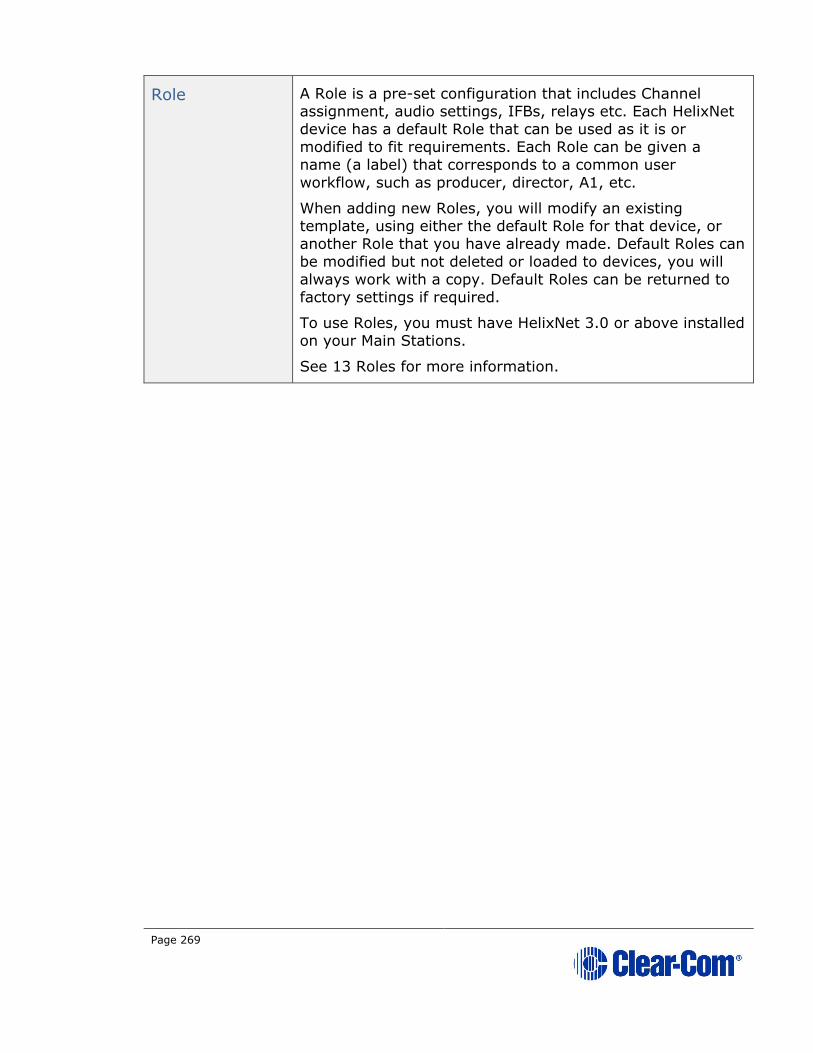
Page 269
Role A Role is a pre-set configuration that includes Channel assignment, audio settings, IFBs, relays etc. Each HelixNet
device has a default Role that can be used as it is or
modified to fit requirements. Each Role can be given a
name (a label) that corresponds to a common user
workflow, such as producer, director, A1, etc.
When adding new Roles, you will modify an existing template, using either the default Role for that device, or
another Role that you have already made. Default Roles can
be modified but not deleted or loaded to devices, you will
always work with a copy. Default Roles can be returned to
factory settings if required.
To use Roles, you must have HelixNet 3.0 or above installed
on your Main Stations.
See 13 Roles for more information.
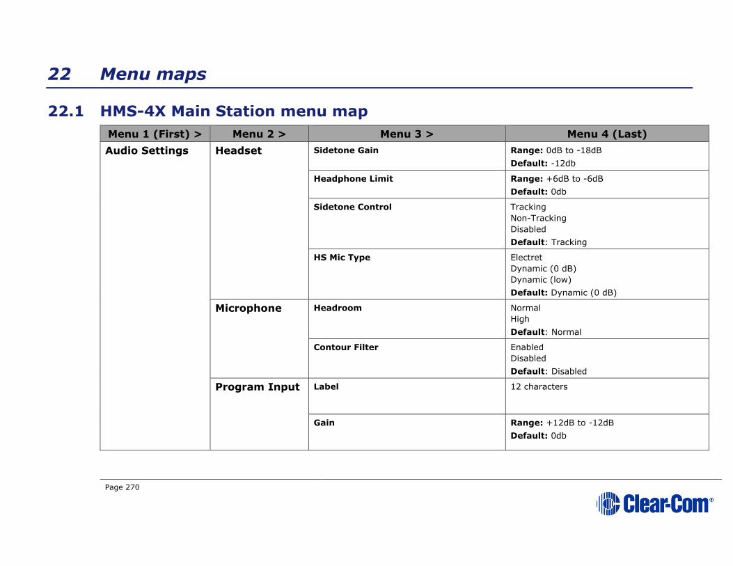
Page 270
22 Menu maps
22.1 HMS-4X Main Station menu map
Menu 1 (First) > Menu 2 > Menu 3 > Menu 4 (Last)
Audio Settings Headset Sidetone Gain Range: 0dB to -18dB
Default: -12db
Headphone Limit Range: +6dB to -6dB
Default: 0db
Sidetone Control Tracking
Non-Tracking
Disabled
Default: Tracking
HS Mic Type Electret
Dynamic (0 dB)
Dynamic (low)
Default: Dynamic (0 dB)
Microphone Headroom Normal
High
Default: Normal
Contour Filter Enabled
Disabled
Default: Disabled
Program Input Label 12 characters
Gain Range: +12dB to -12dB
Default: 0db
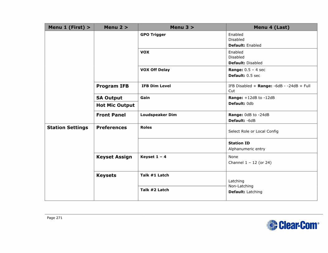
Page 271
Menu 1 (First) > Menu 2 > Menu 3 > Menu 4 (Last)
GPO Trigger Enabled
Disabled
Default: Enabled
VOX Enabled
Disabled
Default: Disabled
VOX Off Delay Range: 0.5 – 4 sec
Default: 0.5 sec
Program IFB IFB Dim Level IFB Disabled + Range: -6dB - -24dB + Full
Cut
SA Output Gain
Range: +12dB to -12dB
Default: 0db Hot Mic Output
Front Panel Loudspeaker Dim Range: 0dB to -24dB
Default: -6dB
Station Settings Preferences Roles Select Role or Local Config
Station ID
Alphanumeric entry
Keyset Assign Keyset 1 – 4 None
Channel 1 – 12 (or 24)
Keysets Talk #1 Latch
Latching
Non-Latching
Default: Latching Talk #2 Latch
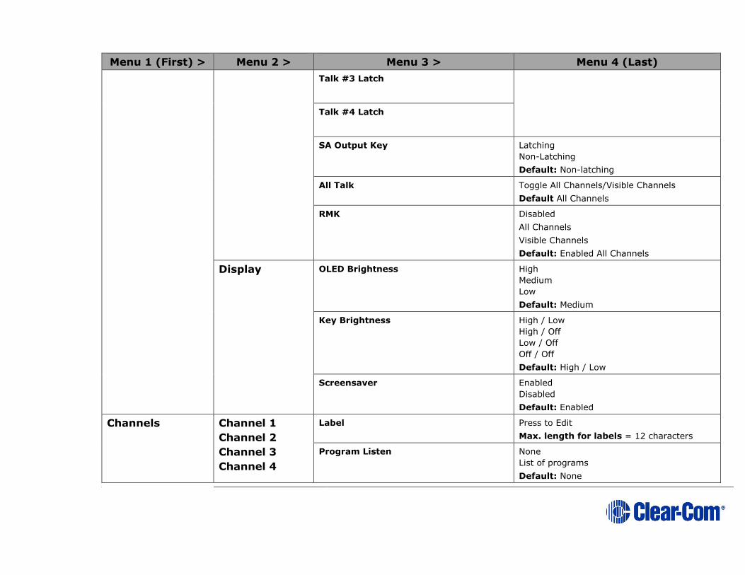
Page 272
Menu 1 (First) > Menu 2 > Menu 3 > Menu 4 (Last)
Talk #3 Latch
Talk #4 Latch
SA Output Key Latching
Non-Latching
Default: Non-latching
All Talk Toggle All Channels/Visible Channels
Default All Channels
RMK Disabled
All Channels
Visible Channels
Default: Enabled All Channels
Display OLED Brightness High
Medium
Low
Default: Medium
Key Brightness High / Low
High / Off
Low / Off
Off / Off
Default: High / Low
Screensaver Enabled
Disabled
Default: Enabled
Channels Channel 1
Channel 2
Channel 3
Channel 4
Label Press to Edit
Max. length for labels = 12 characters
Program Listen None
List of programs
Default: None
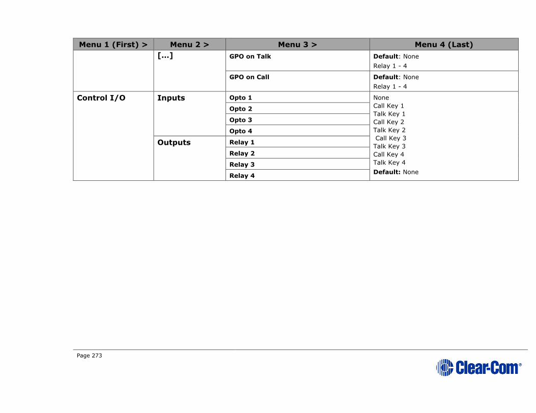
Page 273
Menu 1 (First) > Menu 2 > Menu 3 > Menu 4 (Last)
[…] GPO on Talk Default: None
Relay 1 - 4
GPO on Call Default: None
Relay 1 - 4
Control I/O Inputs Opto 1 None
Call Key 1
Talk Key 1
Call Key 2
Talk Key 2
Call Key 3
Talk Key 3
Call Key 4
Talk Key 4
Default: None
Opto 2
Opto 3
Opto 4
Outputs Relay 1
Relay 2
Relay 3
Relay 4

Page 274
Menu 1 (First) > Menu 2 > Menu 3 > Menu 4 (Last)
Module Settings Slot n /Port
A/B 4W
Channel Assign Disabled
Channel A
Channel B
Channel C
Channel D
Up to the maximum number of licensed
channels.
Default: Disabled
Program Output Unmute
Mute
Default: Mute
GPO Trigger Enabled
Disabled
Default: Enabled
Input Gain Range: +12dB to -12dB
Default: 0db Output Gain
VOX Enabled
Disabled
Default: Disabled
VOX Off Delay Range: [0].5 – 4 secs
Default: [0].5 secs
Slot n /Port
A/B 2W
Channel Assign Disabled
Channel A
Channel B
Channel C
Channel D
Up to the maximum number of licensed
channels.

Page 275
Menu 1 (First) > Menu 2 > Menu 3 > Menu 4 (Last)
Default: Disabled
Program Output Unmute
Mute
Default: Unmute
Auto-Nulling Start
Mode Clear-Com
RTS Audio Pin 2
RTS Audio Pin 3
Default: Clear-Com
GPO Trigger Enabled
Disabled
Default: Enabled
Input Gain Range: -3dB to +3dB
Default: 0db Output Gain
RMK Input Enabled
Disabled
Default: Enabled RMK Output
VOX Enabled
Disabled
Default: Disabled
VOX Off Delay Range: [0].5 – 4 secs
Default: [0].5 secs
Network Stations Preferences Hostname (12 chars)
DHCP enabled/disabled
IP address (enter IP address)
Subnet mask
Gateway
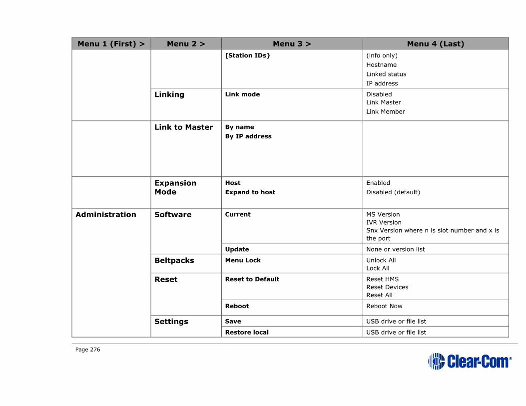
Page 276
Menu 1 (First) > Menu 2 > Menu 3 > Menu 4 (Last)
[Station IDs} (info only)
Hostname
Linked status
IP address
Linking Link mode Disabled
Link Master
Link Member
Link to Master By name
By IP address
Expansion
Mode
Host
Expand to host
Enabled
Disabled (default)
Administration Software Current MS Version
IVR Version
Snx Version where n is slot number and x is
the port
Update None or version list
Beltpacks Menu Lock Unlock All
Lock All
Reset Reset to Default Reset HMS
Reset Devices
Reset All
Reboot Reboot Now
Settings Save USB drive or file list
Restore local USB drive or file list

Page 277
Menu 1 (First) > Menu 2 > Menu 3 > Menu 4 (Last)
Restore system USB drive or file list
Diagnostics Hardware Main PCB Part: [Part_Number]
Revision: [Revision]
Serial number: [Serial number] Slot 1 PCB
Slot 2 PCB
Slot 3 PCB
Temperature Sensor 1 Temperature in °C.
Note:
Single fan on if any sensor > 60°C.
Double fan on if any sensor > 65°C.
Double fan off if < 55°C / single fan off if <
50°C.
Sensor 2
Sensor 3
Powerlines Powerline 1
Powerline 2
Status: [OK or BUSY (according to responses
to MME requests)].
DMC: [MAC of powerline modem]
HMC: [MAC of local blackfin processor]
Beltpacks: [# of beltpacks detected by
powerline modem]
Collision rate: [Percentage (0% when
operating normally)]
Error rate: [Percentage (0% when operating
normally)]
Volts: [Voltage]
Keysets Keyset 1
Keyset 2
Keyset 3
Keyset 4
Name: Channel name
Talkers: Number of talkers on Partyline
Devices: Number of beltpacks listening on
Partyline
Main Stations: Number of Main Stations
listening
2-Wire: Number of 2-Wire ports listening
4-Wire: Number of 4-Wire ports listening

Page 278
22.2 HRS-4X Remote Station menu map
Menu 1 (First) > Menu 2 > Menu 3 > Menu 4 (Last)
Audio Settings Headset Sidetone Gain Range: 0dB to -18dB
Default: -12db
Headphone Limit Off + Range: +6dB to -6dB
Default: 0db
Sidetone Control Tracking
Non-Tracking
Disabled
Default: Tracking
HS Mic Type Electret
Dynamic (0 dB)
Dynamic (low)
Default: Dynamic (0 dB)
Microphone Headroom Normal
High
Default: Normal
Contour Filter Enabled
Disabled
Default: Disabled
Program Input Gain Range: +12dB to -12dB
Default: 0db
IFB Dim Level Range: --6dB to -24dB
Default: Off
GPO Trigger Enabled
Disabled
Default: Enabled
VOX Enabled
Disabled
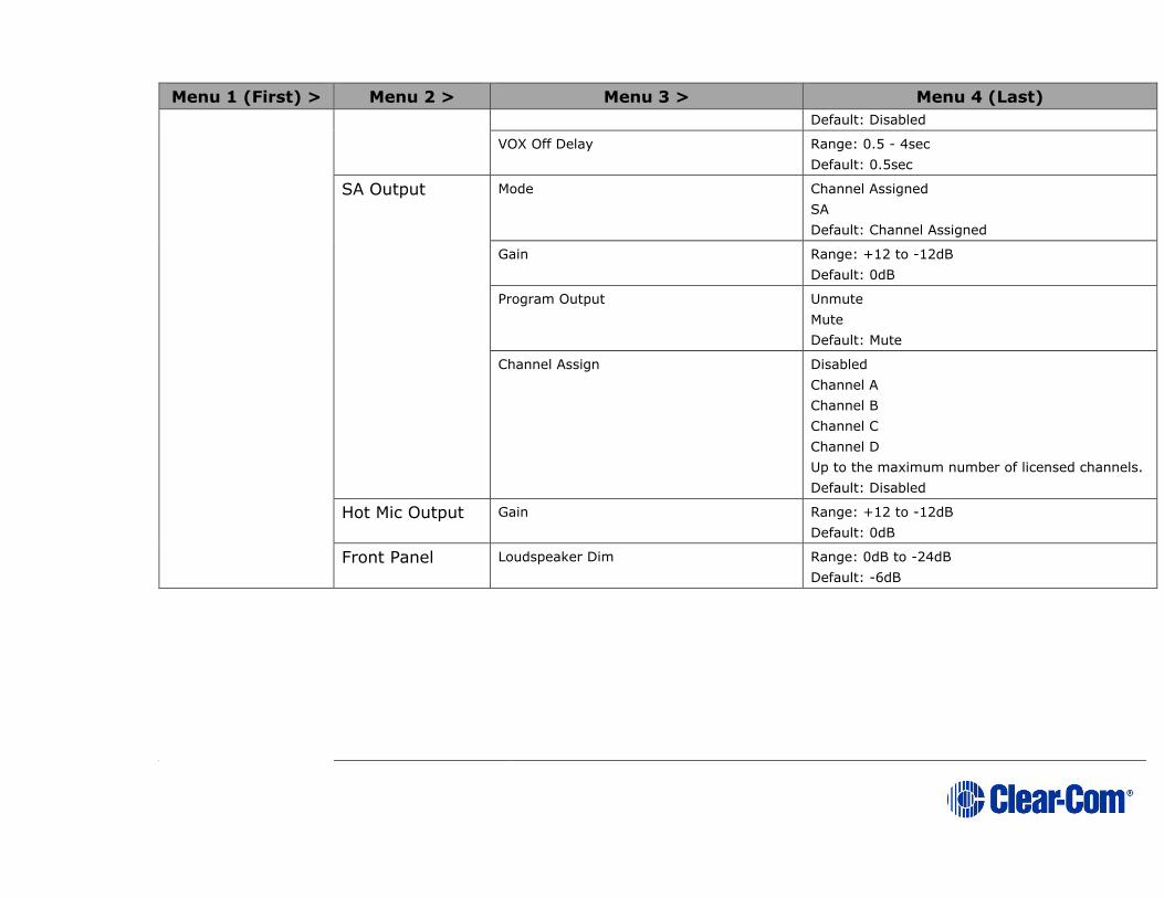
Page 279
Menu 1 (First) > Menu 2 > Menu 3 > Menu 4 (Last)
Default: Disabled
VOX Off Delay Range: 0.5 - 4sec
Default: 0.5sec
SA Output Mode Channel Assigned
SA
Default: Channel Assigned
Gain Range: +12 to -12dB
Default: 0dB
Program Output Unmute
Mute
Default: Mute
Channel Assign Disabled
Channel A
Channel B
Channel C
Channel D
Up to the maximum number of licensed channels.
Default: Disabled
Hot Mic Output Gain Range: +12 to -12dB
Default: 0dB
Front Panel Loudspeaker Dim Range: 0dB to -24dB
Default: -6dB
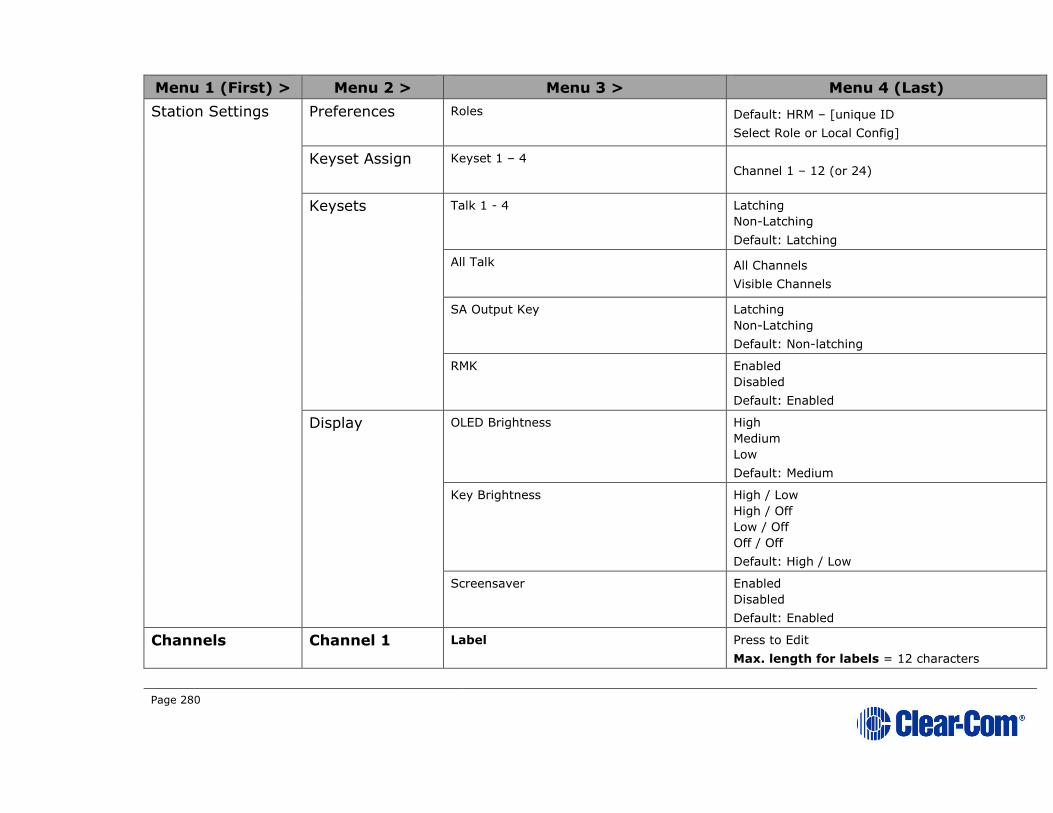
Page 280
Menu 1 (First) > Menu 2 > Menu 3 > Menu 4 (Last)
Station Settings Preferences Roles Default: HRM – [unique ID
Select Role or Local Config]
Keyset Assign Keyset 1 – 4 Channel 1 – 12 (or 24)
Keysets Talk 1 - 4 Latching
Non-Latching
Default: Latching
All Talk All Channels
Visible Channels
SA Output Key Latching
Non-Latching
Default: Non-latching
RMK Enabled
Disabled
Default: Enabled
Display OLED Brightness High
Medium
Low
Default: Medium
Key Brightness High / Low
High / Off
Low / Off
Off / Off
Default: High / Low
Screensaver Enabled
Disabled
Default: Enabled
Channels Channel 1 Label Press to Edit
Max. length for labels = 12 characters
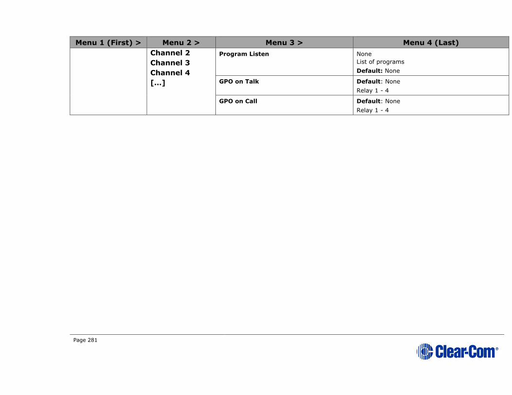
Page 281
Menu 1 (First) > Menu 2 > Menu 3 > Menu 4 (Last)
Channel 2
Channel 3
Channel 4
[…]
Program Listen None
List of programs
Default: None
GPO on Talk Default: None
Relay 1 - 4
GPO on Call Default: None
Relay 1 - 4
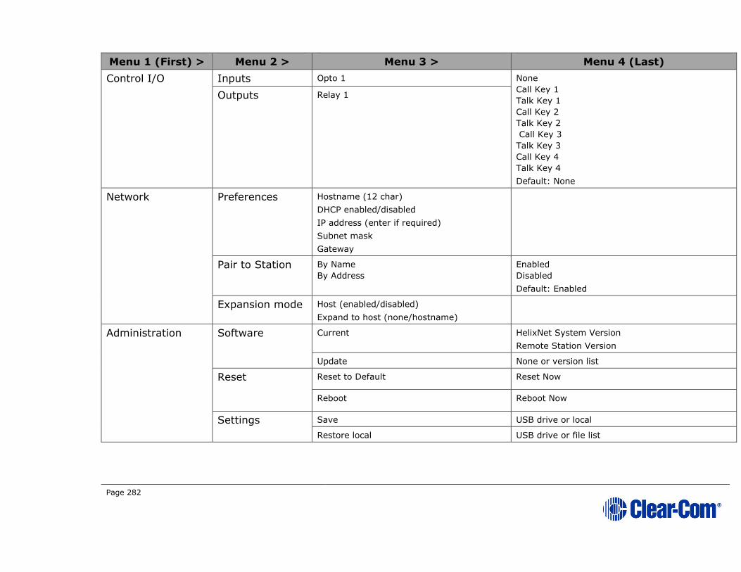
Page 282
Menu 1 (First) > Menu 2 > Menu 3 > Menu 4 (Last)
Control I/O Inputs Opto 1 None
Call Key 1
Talk Key 1
Call Key 2
Talk Key 2
Call Key 3
Talk Key 3
Call Key 4
Talk Key 4
Default: None
Outputs Relay 1
Network Preferences Hostname (12 char)
DHCP enabled/disabled
IP address (enter if required)
Subnet mask
Gateway
Pair to Station By Name
By Address
Enabled
Disabled
Default: Enabled
Expansion mode Host (enabled/disabled)
Expand to host (none/hostname)
Administration Software Current HelixNet System Version
Remote Station Version
Update None or version list
Reset Reset to Default Reset Now
Reboot Reboot Now
Settings Save USB drive or local
Restore local USB drive or file list
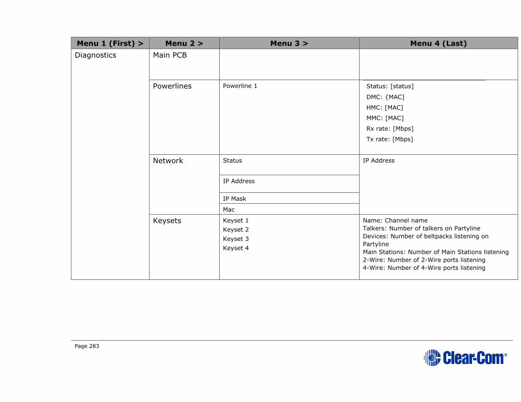
Page 283
Menu 1 (First) > Menu 2 > Menu 3 > Menu 4 (Last)
Diagnostics Main PCB
Powerlines Powerline 1 Status: [status]
DMC: {MAC]
HMC: [MAC]
MMC: [MAC]
Rx rate: [Mbps]
Tx rate: [Mbps]
Network Status IP Address
IP Address
IP Mask
Mac
Keysets Keyset 1
Keyset 2
Keyset 3
Keyset 4
Name: Channel name
Talkers: Number of talkers on Partyline
Devices: Number of beltpacks listening on
Partyline
Main Stations: Number of Main Stations listening
2-Wire: Number of 2-Wire ports listening
4-Wire: Number of 4-Wire ports listening

Page 284
22.3 HKB-4X Speaker Station menu map
Menu 1 (First) > Menu 2 > Menu 3 > Menu 4 (Last)
Roles Select Role or Local Config.
Audio Settings Headset Sidetone Gain Range: 0dB to -18dB
Default: -12db
Headphone Limit Off + Range: +6dB to -6dB
Default: 0db
Sidetone Control Tracking
Non-Tracking
Disabled
Default: Tracking
HS Mic Type Electret (-15dB)
Dynamic (0 dB)
Dynamic (low)
Default: Dynamic (0 dB)
Microphone Headroom Normal
High
Default: Normal
Contour Filter Enabled
Disabled
Default: Disabled
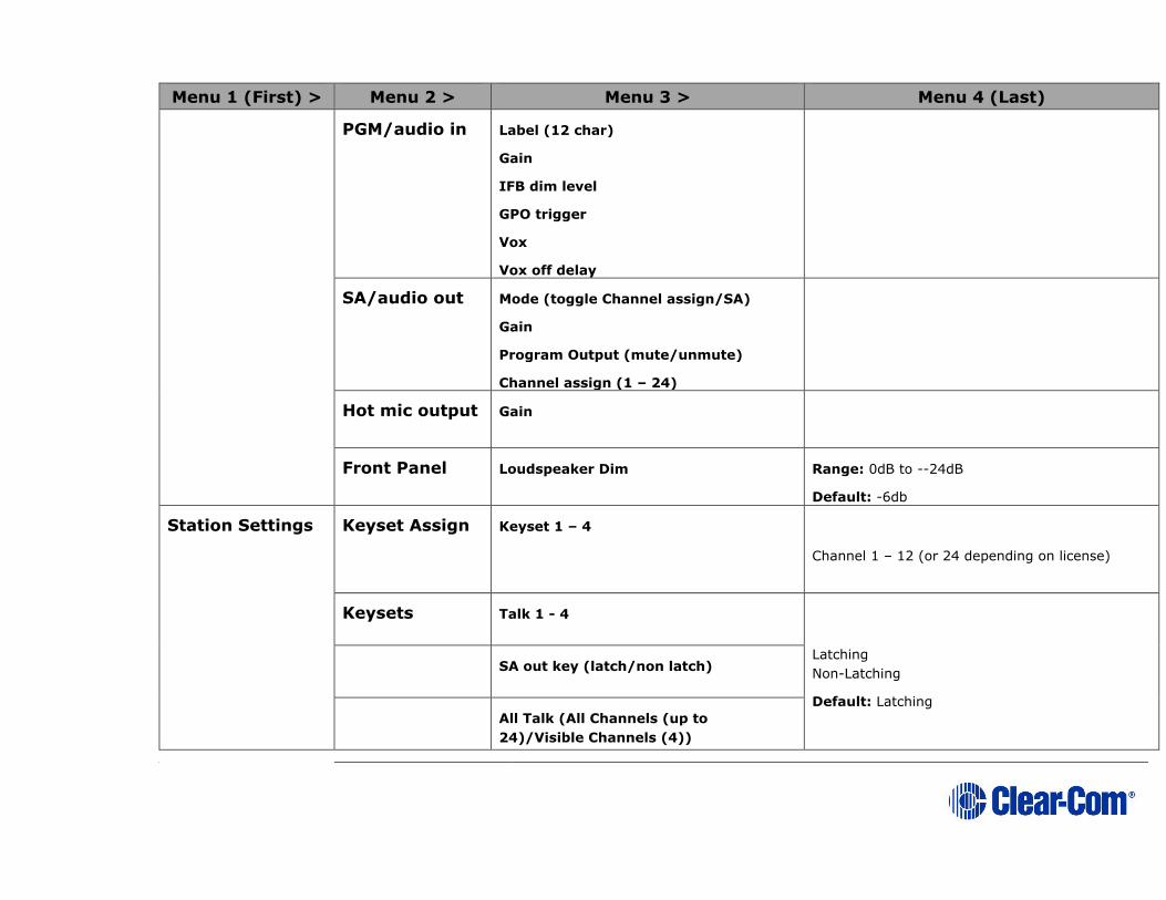
Page 285
Menu 1 (First) > Menu 2 > Menu 3 > Menu 4 (Last)
PGM/audio in Label (12 char)
Gain
IFB dim level
GPO trigger
Vox
Vox off delay
SA/audio out Mode (toggle Channel assign/SA)
Gain
Program Output (mute/unmute)
Channel assign (1 – 24)
Hot mic output Gain
Front Panel Loudspeaker Dim Range: 0dB to --24dB
Default: -6db
Station Settings Keyset Assign Keyset 1 – 4
Channel 1 – 12 (or 24 depending on license)
Keysets Talk 1 - 4
Latching
Non-Latching
Default: Latching
SA out key (latch/non latch)
All Talk (All Channels (up to
24)/Visible Channels (4))
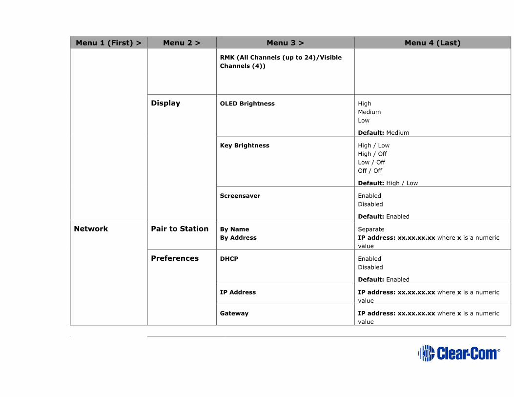
Page 286
Menu 1 (First) > Menu 2 > Menu 3 > Menu 4 (Last)
RMK (All Channels (up to 24)/Visible
Channels (4))
Display OLED Brightness High
Medium
Low
Default: Medium
Key Brightness High / Low
High / Off
Low / Off
Off / Off
Default: High / Low
Screensaver Enabled
Disabled
Default: Enabled
Network Pair to Station By Name
By Address
Separate
IP address: xx.xx.xx.xx where x is a numeric
value
Preferences DHCP Enabled
Disabled
Default: Enabled
IP Address IP address: xx.xx.xx.xx where x is a numeric
value
Gateway IP address: xx.xx.xx.xx where x is a numeric
value

Page 287
Menu 1 (First) > Menu 2 > Menu 3 > Menu 4 (Last)
Subnet Mask IP address: xx.xx.xx.xx where x is a numeric
value
Administration Software Current HelixNet
Speaker Station
License Current/Enter code
Reset Reset to Default Reset Now
Reboot Reboot Now
Setting Save/restore
Diagnostics Powerlines Powerline 1 Status: [OK or BUSY (according to responses to
MME requests)].
DMC:[MAC of powerline modem]
HMC: [MAC of local blackfin processor
Rx rate:[Mbps]
Tx rate:[Mbps]
Status:[status]
IP Addr [IP Address]
IP Mask [Subnet Mask]
MAC:[MAC Address]
Networking Ethernet
Keysets Keyset 1
Keyset 2
Keyset 3
Keyset 4
Name: Channel name
Talkers: Number of talkers on Partyline
Devices: Number of beltpacks listening on
Partyline
Main Stations: Number of Main Stations listening
2-Wire: Number of 2-Wire ports listening
4-Wire: Number of 4-Wire ports listening

Page 288
Menu 1 (First) > Menu 2 > Menu 3 > Menu 4 (Last)
Hardware
Voice clients
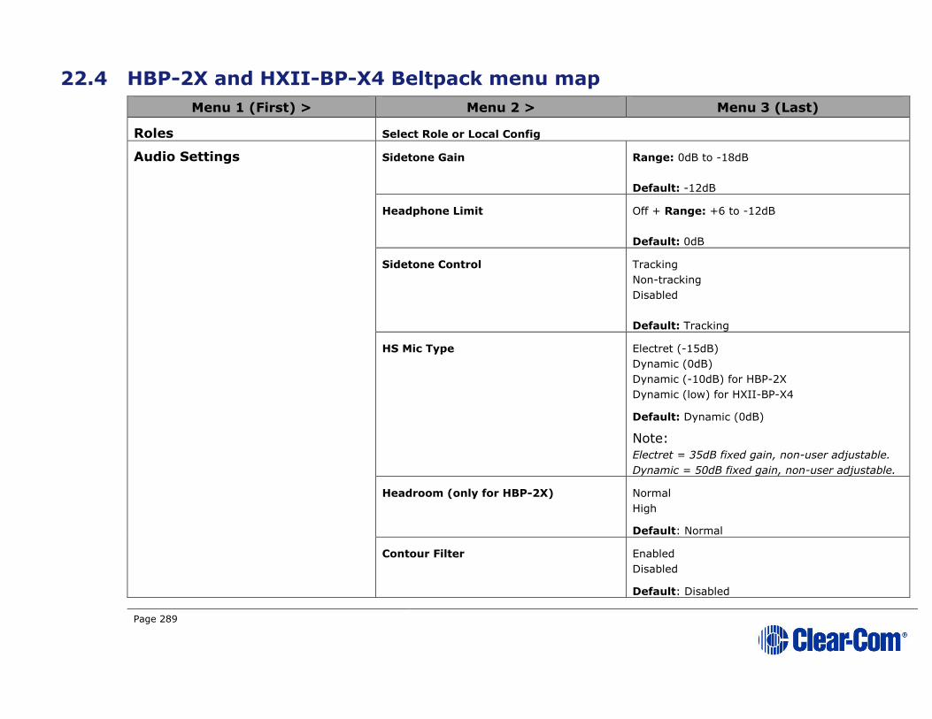
Page 289
22.4 HBP-2X and HXII-BP-X4 Beltpack menu map
Menu 1 (First) > Menu 2 > Menu 3 (Last)
Roles Select Role or Local Config
Audio Settings Sidetone Gain Range: 0dB to -18dB
Default: -12dB
Headphone Limit Off + Range: +6 to -12dB
Default: 0dB
Sidetone Control Tracking
Non-tracking
Disabled
Default: Tracking
HS Mic Type Electret (-15dB)
Dynamic (0dB)
Dynamic (-10dB) for HBP-2X
Dynamic (low) for HXII-BP-X4
Default: Dynamic (0dB)
Note:
Electret = 35dB fixed gain, non-user adjustable.
Dynamic = 50dB fixed gain, non-user adjustable.
Headroom (only for HBP-2X) Normal
High
Default: Normal
Contour Filter Enabled
Disabled
Default: Disabled
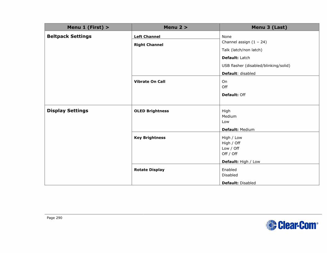
Page 290
Menu 1 (First) > Menu 2 > Menu 3 (Last)
Beltpack Settings Left Channel None
Channel assign (1 – 24)
Talk (latch/non latch)
Default: Latch
USB flasher (disabled/blinking/solid)
Default: disabled
Right Channel
Vibrate On Call On
Off
Default: Off
Display Settings OLED Brightness High
Medium
Low
Default: Medium
Key Brightness High / Low
High / Off
Low / Off
Off / Off
Default: High / Low
Rotate Display Enabled
Disabled
Default: Disabled

Page 291
Menu 1 (First) > Menu 2 > Menu 3 (Last)
Screensaver Channel
Hostname
Role (default)
Blank
Disabled
Network (HBP-2X and HXII-BP-
X4 over powerline)
IP Address IP address: xx.xx.xx.xx where x is a numeric
value
Network (HXII-BP-X4 powered over Ethernet)
Pair to Station By Name
By Address
Preferences DHCP
IP address
Gateway
Subnet mask
Administration Software Version npl-1.0.x, uboot
Software Update npl-1.0.x
Reset to Default Reset Now
Hardware
Important Note:
There are 4 levels of Menu for Hardware
Main PCB
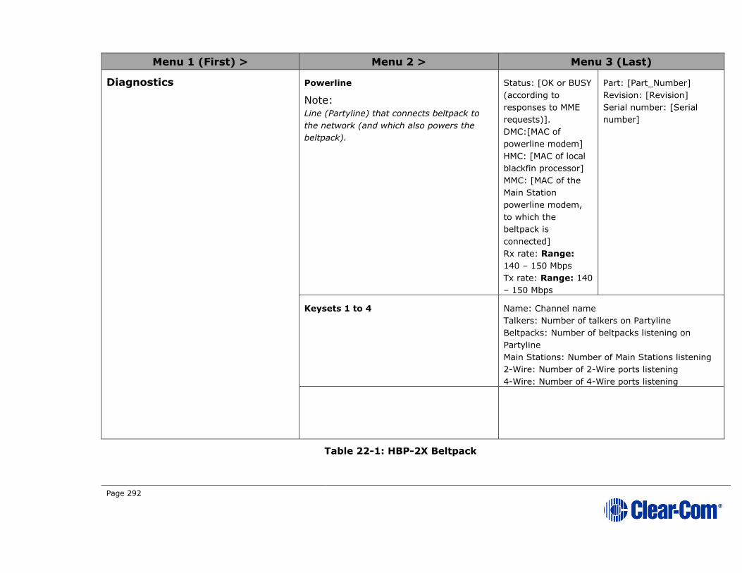
Page 292
Menu 1 (First) > Menu 2 > Menu 3 (Last)
Diagnostics Powerline
Note:
Line (Partyline) that connects beltpack to
the network (and which also powers the
beltpack).
Status: [OK or BUSY
(according to
responses to MME
requests)].
DMC:[MAC of
powerline modem]
HMC: [MAC of local
blackfin processor]
MMC: [MAC of the
Main Station
powerline modem,
to which the
beltpack is
connected]
Rx rate: Range:
140 – 150 Mbps
Tx rate: Range: 140
– 150 Mbps
Part: [Part_Number]
Revision: [Revision]
Serial number: [Serial
number]
Keysets 1 to 4 Name: Channel name
Talkers: Number of talkers on Partyline
Beltpacks: Number of beltpacks listening on
Partyline
Main Stations: Number of Main Stations listening
2-Wire: Number of 2-Wire ports listening
4-Wire: Number of 4-Wire ports listening
Table 22-1: HBP-2X Beltpack

Page 293
23 Menu trees
This chapter provides tree diagrams of the menu structure of all the HelixNet
devices. Use these diagrams to gain a quick overview of what menu options are
available, and where to find them.
Note: Items marked with an asterisk (*) are not present in expansion mode.

Page 294
Table 23-1 Main Station menu tree
Audio Settings
Control I/O
Module Settings
Administration
Station Settings
Channels
Networking
Diagnostics
Headset*
Microphone*
Program Input
Program IFB
SA Output*
Hot Mic Output*
Front Panel*
Sidetone Gain
Headphone Limit
Headphone Gain
Sidetone Control
HS Mic Type
Adjust Level
Adjust Level
Adjust Level
Tracking/Non-tracking/Disabled
Electret/Dynamic
Headroom
Contour Filter
Label
Gain
GPO Trigger
VOX
VOX Off Delay
Enter 12 character label
Adjust Level
Toggle GPO Trigger
Toggle VOX
Adjust Level
Toggle Normal/High
Toggle Enable/Disable
IFB Dim Level Adjust Level
Gain Adjust Level
Gain Adjust Level
Loudspeaker Dim Adjust Level
Preferences
Keyset Assign
Keysets
Display*
Roles Select Local Config or Role
Keyset 1 to 4 Up to 24 Channels
Talk 1 to 4Latching/Non-Latching/
Disabled
SA Out Key
All Talk
RMK
Toggle Latching/Non-Latching
Toggle All Channels/Visible Channels
All Channels/Visible Channels/Disabled
OLED Brightness
Key Brightness
Screensaver
High/Medium/Low
High/Low, High/Off, Low/Off, Off/Off
Toggle Enabled/DisabledChannel 1 to 24
Label
Program Listen
GPO on Talk
GPO on Call
Enter 12 character label
None/Programs
None/Relay 1 to 4
None/Relay 1 to 4
Inputs
Outputs
Opto 1 to 4
Relay 1 to 4/SA
None/Call or Talk 1 to 4
None/Call or Talk 1 to 4/SA
Slot n/Port A/B 4W
Slot n/Port A/B 2W
Slot n Ethernet
Slot n Fiber
Slot n
Software
License
Reset
Settings
Hardware
Temperature
Powerlines
Keysets
Preferences
Stations
Linking
Link To Master
Expansion Mode
Channel Assign
Program Output
Input Gain
Output Gain
GPO Trigger
VOX
VOX Off Delay
Disabled/Channel 1 to 24
Toggle Unmute/Mute
Adjust Level
Adjust Level
Toggle Enabled/Disabled
Toggle Enabled/Disabled
Adjust Level
Channel Assign
Program Output
Auto Nulling
Mode
Input Gain
Output Gain
GPO Trigger
RMK Input
RMK Output
VOX
VOX Off Delay
Disabled/channel 1 to 24
Toggle Unmute/Mute
Start
Clear-Com/RTS Audio Pin 2/RTS Audio Pin 3
Adjust Level
Adjust Level
Toggle Enabled/Disabled
Toggle Enabled/Disabled
Toggle Enabled/Disabled
Toggle Enabled/Disabled
Adjust Level
Empty
Hostname
DHCP
IP Address
Subnet Mask
Gateway
Enter 12 character label
Toggle Enabled/Disabled
Enter IPv4 Address
Enter IPv4 Address
Enter IPv4 Address
Station IDs
Link ModeDisabled/Master/
Member
By Name
By Address
None/Station IDs
Enter IPv4 Address
Host/Expand to HostToggle Enabled/
Disabled
Current
Update
Current
Enter Code
Reset To Default
Reboot
Save
Restore
Main PCB
Slot 1 PCB
Slot 2 PCB
Slot 3 PCB
Sensor 1
Sensor 2
Sensor 3
Powerline 1/2
Keyset 1 to 4
System IDNo. of Channels (12
or 24)
Hardware
Main Station front menu screens

Page 295
Table 23-2 Remote Station menu tree
Audio Settings
Control I/O
Administration
Station Settings
Channels
Networking
Diagnostics
Headset
Microphone
PGM/Audio in
SA/Audio out
Hot Mic Output
Front Panel
Sidetone Gain
Headphone Limit
Headphone Gain
Sidetone Control
HS Mic Type
Adjust Level
Adjust Level
Adjust Level
Tracking/Non-tracking/Disabled
Electret/Dynamic
Headroom
Contour Filter
Label
Gain
IFB Dim Level
VOX
VOX Off Delay
Enter 12 character label
Adjust Level
Toggle GPO Trigger
Adjust Level
Toggle Normal/High
Toggle Enable/Disable
Adjust Level
Gain Adjust Level
Gain Adjust Level
Loudspeaker Dim Adjust Level
Keyset Assign
Keysets
Display
Select Local Config or Role
Keyset 1 to 4 Up to 24 Channels
Talk 1 to 4Latching/Non-Latching/
Disabled
SA Out Key
All Talk
OPT (RMK)
Toggle Latching/Non-Latching
Toggle All Channels/Visible Channels
All Channels/Visible Channels/Disabled
OLED Brightness
Key Brightness
Screensaver
High/Medium/Low
High/Low, High/Off, Low/Off, Off/Off
Toggle Enabled/DisabledChannel 1 to 24
Label
Program Listen
GPO on Talk
GPO on Call
Enter 12 character label
None/Programs
None/Relay 1 to 4
None/Relay 1 to 4
Inputs
Outputs
Opto 1
Relay 1
None/Call or Talk 1 to 4
None/Call or Talk 1 to 4
Software
Reset
SettingsHardware
Powerlines
Keysets
Preferences
Pair to Station
Expansion Mode
Hostname
DHCP
IP Address
Subnet Mask
Gateway
Enter 12 character label
Toggle Enabled/Disabled
Enter IPv4 Address
Enter IPv4 Address
Enter IPv4 Address
By Name
By AddressNone/Station IDs
Enter IPv4 Address
HostToggle Enabled/
Disabled
Current
Update
Reset To Default
Reboot
Save
Restore local
Main PCB
Powerline
Keyset 1 to 4
GPO Trigger
Adjust Level
Mode
Channel Assign
Program Output
Toggle Channel Assign/SA
Toggle Unmute/Mute
Select channel 1 to 24
Expand to HostToggle None/
Hostname
Networking Ethernet
Remote Station front screensmenu
Role

Page 296
Table 23-3 Speaker Station menu tree
Audio Settings
Module Settings
Administration
Station Settings
Networking
Diagnostics
Headset
Microphone
Front Panel
Sidetone Gain
Headphone Limit
Headphone Gain
Sidetone Control
HS Mic Type
Adjust Level
Adjust Level
Adjust Level
Tracking/Non-tracking/Disabled
Electret/Dynamic
Headroom
Contour Filter
Toggle Normal/High
Toggle Enable/Disable
Loudspeaker Dim Adjust LevelKeyset Assign
Keysets
Display
Select Local Config or Role
Keyset 1 to 4 Up to 24 Channels
Talk 1 to 4Latching/Non-Latching/
Disabled
SA Out Key
All Talk
RMK
Toggle Latching/Non-Latching
Toggle All Channels/Visible Channels
All Channels/Visible Channels/Disabled
OLED Brightness
Key Brightness
Screensaver
High/Medium/Low
High/Low, High/Off, Low/Off, Off/Off
Toggle Enabled/Disabled
Slot n/Port A/B 4W
Slot n/Port A/B 2W
Slot n Ethernet
Slot n Fiber
Slot n
Software
License
Reset
Settings
Powerlines
Networking
Keysets
Hardware
Preferences
Pair to Station
Channel Assign
Program Output
Input Gain
Output Gain
GPO Trigger
VOX
VOX Off Delay
Disabled/Channel 1 to 24
Toggle Unmute/Mute
Adjust Level
Adjust Level
Toggle Enabled/Disabled
Toggle Enabled/Disabled
Adjust Level
Channel Assign
Program Output
Auto Nulling
Mode
Input Gain
Output Gain
GPO Trigger
RMK Input
RMK Output
VOX
VOX Off Delay
Disabled/channel 1 to 24
Toggle Unmute/Mute
Start
Clear-Com/RTS Audio Pin 2/RTS Audio Pin 3
Adjust Level
Adjust Level
Toggle Enabled/Disabled
Toggle Enabled/Disabled
Toggle Enabled/Disabled
Toggle Enabled/Disabled
Adjust Level
Empty
DHCP
IP Address
Subnet Mask
Gateway
Toggle Enabled/Disabled
Enter IPv4 Address
Enter IPv4 Address
Enter IPv4 Address
By Name
By Address
None/Station IDs
Enter IPv4 Address
Current
Update
Current
Enter Code
Reset To Default
Reboot
Save
Restore
Ethernet
1 - 4
Voice clients
Speaker Station front screensmenu
Roles

Page 297
Table 23-4 Beltpack menu tree
Roles
Display Settings
Administration
Audio Settings
Beltpack Settings
Diagnostics
Local Config
Roles
Sidetone Gain
Headphone Limit
Headphone Gain
Sidetone Control
HS Mic Type
Adjust Level
Adjust Level
Adjust Level
Tracking/Non-tracking/Disabled
Electret/Dynamic
Screensave ChannelHostnameRoleBlankDisabled
Left Keyset Channel Assign
Talk
USB Flasher
Hardware
Mic Headroom (only for HBP-2X)
Contour Filter
Toggle Normal/High
Toggle Enable/Disable
Right keyset
Vibrate On Call
None/Channel 1-24/Stacked key
Latching/Non Latching/DisabledDisabled/Blinking/
SolidOn/Off
Software version
Reset to default
View hostnameSoftware version
Reset Now
Network (applies to HBP-2X)
Keyset 1 - 2
View onlyName (of Channel)TalkersDevicesMain Station 2-wire4-wire
Powerline
Keysets
PCB
Powerline
IP address
Beltpack Menuscreens
Network (applies to HXII-BP-X4)
Preferences
Pair to Station
DHCP
IP Address
Subnet Mask
Gateway
Toggle Enabled/Disabled
Enter IPv4 Address
Enter IPv4 Address
Enter IPv4 Address
By Name
By Address
None/Station IDs
Enter IPv4 Address
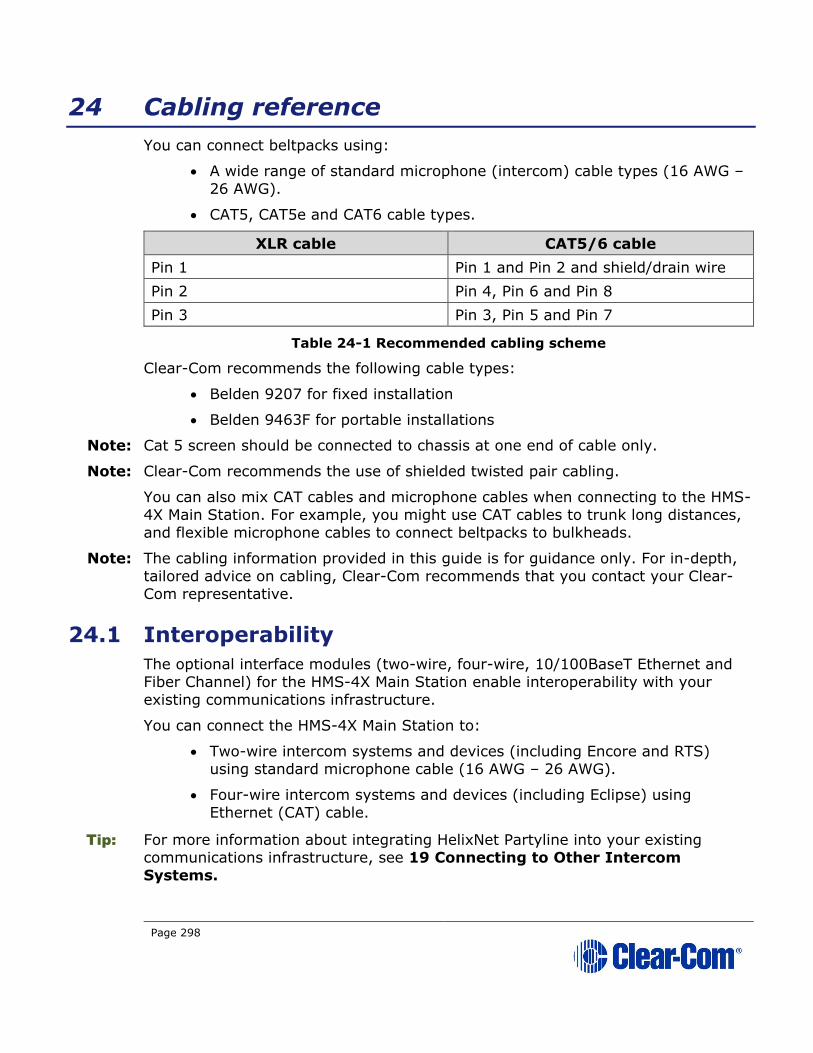
Page 298
24 Cabling reference
You can connect beltpacks using:
• A wide range of standard microphone (intercom) cable types (16 AWG –
26 AWG).
• CAT5, CAT5e and CAT6 cable types.
XLR cable CAT5/6 cable
Pin 1 Pin 1 and Pin 2 and shield/drain wire
Pin 2 Pin 4, Pin 6 and Pin 8
Pin 3 Pin 3, Pin 5 and Pin 7
Table 24-1 Recommended cabling scheme
Clear-Com recommends the following cable types:
• Belden 9207 for fixed installation
• Belden 9463F for portable installations
Note: Cat 5 screen should be connected to chassis at one end of cable only.
Note: Clear-Com recommends the use of shielded twisted pair cabling.
You can also mix CAT cables and microphone cables when connecting to the HMS-
4X Main Station. For example, you might use CAT cables to trunk long distances,
and flexible microphone cables to connect beltpacks to bulkheads.
Note: The cabling information provided in this guide is for guidance only. For in-depth,
tailored advice on cabling, Clear-Com recommends that you contact your Clear-
Com representative.
24.1 Interoperability
The optional interface modules (two-wire, four-wire, 10/100BaseT Ethernet and
Fiber Channel) for the HMS-4X Main Station enable interoperability with your
existing communications infrastructure.
You can connect the HMS-4X Main Station to:
• Two-wire intercom systems and devices (including Encore and RTS) using standard microphone cable (16 AWG – 26 AWG).
• Four-wire intercom systems and devices (including Eclipse) using
Ethernet (CAT) cable.
Tip: For more information about integrating HelixNet Partyline into your existing communications infrastructure, see 19 Connecting to Other Intercom
Systems.

Page 299
24.2 Cable capacitance versus distance
Standard microphone cables impose distance limitations at their upper limits due
to cable capacitance.
If your priority is audio quality, experiment with attaching one or two fewer
devices to each line. Your choice of topology (daisy chain, star or tree) may also
impact audio quality over distance.
Manufacturer Cable type Gauge
(AWG)
Style Attenuation
/ 100m
Belden 9463f 20 Std 16 dB
Belden 9207 20 Std 9 dB
Belden 1533P 24 Cat5e 11 dB
Table 24-2: Cable capacitance
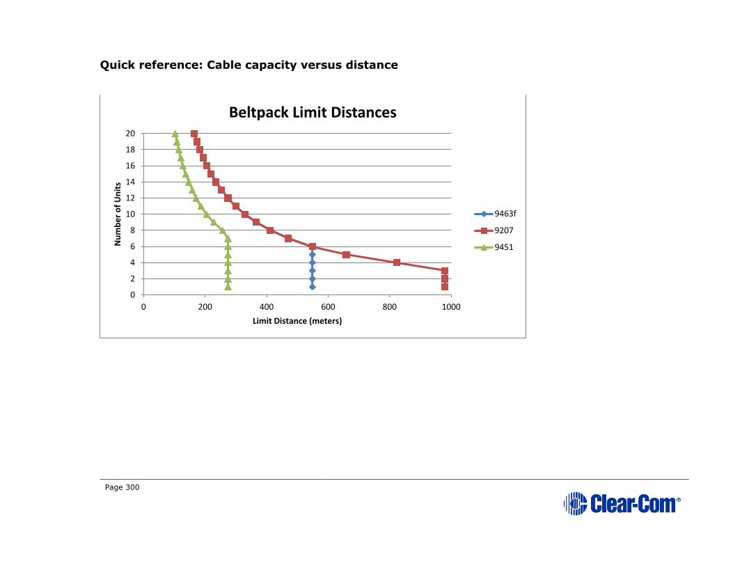
Page 300
Quick reference: Cable capacity versus distance
0
2
4
6
8
10
12
14
16
18
20
0 200 400 600 800 1000
Nu
mb
er
of
Un
its
Limit Distance (meters)
Beltpack Limit Distances
9463f
9207
9451

Page 301
0
1
2
3
4
5
6
7
0 200 400 600 800 1000
Nu
mb
er
of
Un
its
Limit Distance (meters)
Remote Station Limit Distances
9463f
9207
9451
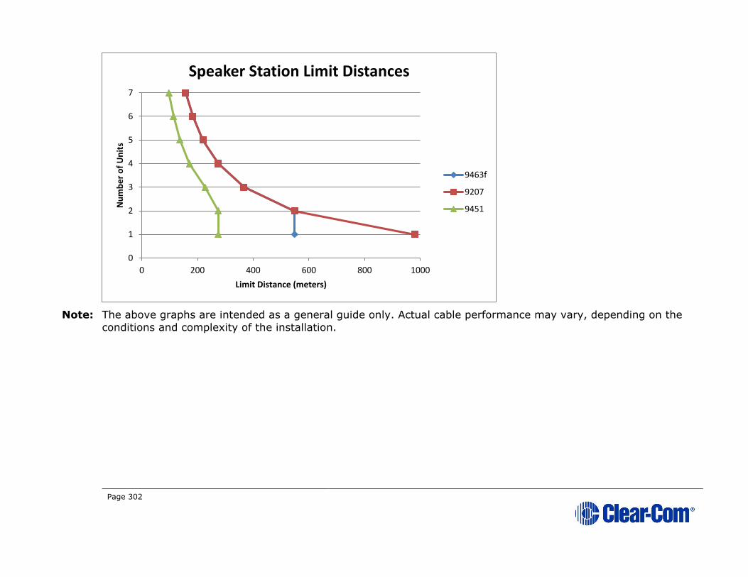
Page 302
Note: The above graphs are intended as a general guide only. Actual cable performance may vary, depending on the
conditions and complexity of the installation.
0
1
2
3
4
5
6
7
0 200 400 600 800 1000
Nu
mb
er
of
Un
its
Limit Distance (meters)
Speaker Station Limit Distances
9463f
9207
9451

Page 303
24.3 Cable connections
The diagrams on the following pages reference the following labels and notes.
Label Manufacturer Part Number Description
1
Clear-Com HMS-4X HelixNet Main Station
2
Belden 8760,9207
Or
9463F
18 or 20 AWG twisted pair cable
terminated with 3-pin XLR
3
Middle Atlantic (or
equivalent)
CH-1 1 RU shielded chassis
4
Neutrik (or
equivalent)
NC3FD-L-B-1 3 pole female chassis mount
5
Neutrik (or
equivalent) NC3MD-L-B-1 3 pole male chassis mount
6
Neutrik (or
equivalent) NA3MDF 3 PIN XLR M-F FEED THRU
ADAPTER
7
Belden (or existing
cabling) 1351A or 1533P 24 AWG, shielded cat 6 cabling
8
Belden 8760,9207 or 9463F
XLR3 M-F patch cord
9
Belden 8760,9207 or 9463F
18 or 20 AWG twisted pair cable
Table 24-3 Label descriptions
Label Note
1 Wire in accordance with Table 24-5
2 Equipment rack, breakout box chassis and patch panel must be
connected to safety earth
3 Connect up to 32 wall plate locations to patch panel with individual CAT
5 cables
4 If multiple wall plates are co-located at a remote location, daisy chain their wiring at the remote location and connect a single CAT 5 cable
from the remote location back to the patch panel
5 Use short length, high quality XLR patch cords with shielded connectors
6 Do not patch between separate power lines
7 Assemble item 6 to panel with male connectors to front

Page 304
Figure 24-1 Wiring diagram
CAT5
12
3
Cat5 pins 1, 2 and shield
Cat5 pins 3, 5 and 7
Cat5 pins 4, 6 and 8
RJ-45 XLR
1 white/orange 1
1
3
2
3232
XLR
12345678
2 Orange
3 White/green
4 Blue
5 White/blue6 Green7 White/brown8 Brown
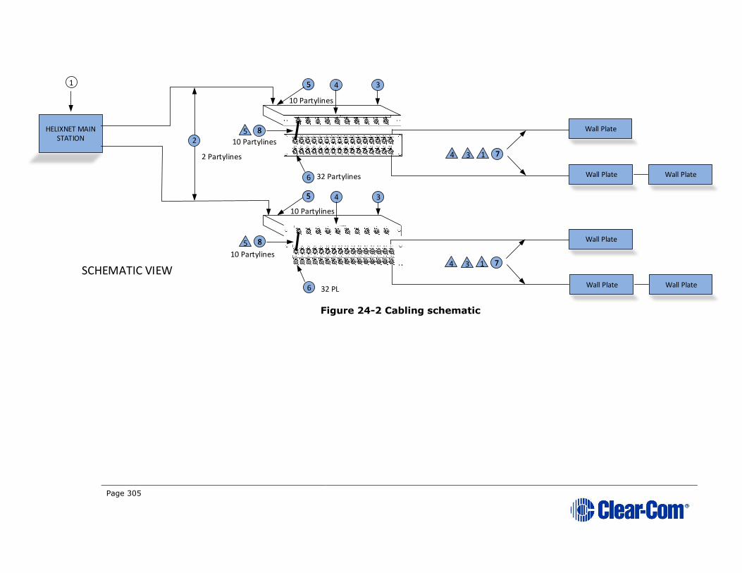
Page 305
Figure 24-2 Cabling schematic
HELIXNET MAIN STATION
1 3
2
55 4
10 Partylines
6 32 Partylines
Wall Plate
77
Wall Plate Wall Plate
355 4
6 32 PL
Wall Plate
Wall Plate Wall Plate
2 Partylines
SCHEMATIC VIEW
88
10 Partylines
88
10 Partylines
5
5
4 3 1
774 3 1
10 Partylines

Page 306
Figure 24-3 Cabling side view
XLR
XLRXLR
XLR
M F M
F
Wall Plate
XLR
XLRXLR
Wall Plate Wall Plate
6
4 10 PL55 9
6 7
2

Page 307
Figure 24-4 Front view
POWER LINE #1A
POWER LINE #1AWALL PLATE
POWER LINE #1B
POWER LINE #1BWALL PLATE
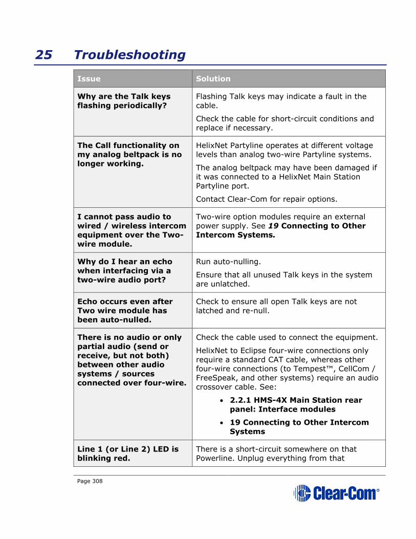
Page 308
25 Troubleshooting
Issue Solution
Why are the Talk keys
flashing periodically?
Flashing Talk keys may indicate a fault in the
cable.
Check the cable for short-circuit conditions and
replace if necessary.
The Call functionality on my analog beltpack is no
longer working.
HelixNet Partyline operates at different voltage levels than analog two-wire Partyline systems.
The analog beltpack may have been damaged if
it was connected to a HelixNet Main Station
Partyline port.
Contact Clear-Com for repair options.
I cannot pass audio to
wired / wireless intercom equipment over the Two-
wire module.
Two-wire option modules require an external
power supply. See 19 Connecting to Other Intercom Systems.
Why do I hear an echo
when interfacing via a
two-wire audio port?
Run auto-nulling.
Ensure that all unused Talk keys in the system
are unlatched.
Echo occurs even after
Two wire module has
been auto-nulled.
Check to ensure all open Talk keys are not
latched and re-null.
There is no audio or only
partial audio (send or
receive, but not both) between other audio
systems / sources
connected over four-wire.
Check the cable used to connect the equipment.
HelixNet to Eclipse four-wire connections only
require a standard CAT cable, whereas other four-wire connections (to Tempest™, CellCom /
FreeSpeak, and other systems) require an audio
crossover cable. See:
• 2.2.1 HMS-4X Main Station rear
panel: Interface modules
• 19 Connecting to Other Intercom
Systems
Line 1 (or Line 2) LED is
blinking red.
There is a short-circuit somewhere on that
Powerline. Unplug everything from that

Page 309
Powerline and add cables and Beltpacks one at a time until you find the short-circuit.
Line 1 (or Line 2) LED is steady red and one or
more Beltpack has no
bars showing up for
signal strength.
There are digital errors or there is cross-talk on that Powerline. Look at the Diagnostics-
>Powerlines->Powerline 1(or 2) page.
If the number of Beltpacks showing there is
greater than what you physically connected to
that Powerline, cross-talk is happening between the Powerlines. Make sure you are using
properly shielded Mic cables or Cat cables.
If the number of Beltpacks showing there does
match what you physically connected to that
Powerline and errors or high collision rate is
displayed, verify that you don’t exceed the number of Beltpacks per Powerline or distance
as per the Cable capacity versus distance table.
High collision rate means communication issues
on the powerline. Possible causes are:
• Unshielded or bad cables
• Powerline 1 looped back into Powerline 2
(or from one HMS to another)
• Cables too long
• Too many cables in the infrastructure
(even unconnected strand count)
• Too many devices on the Powerline
• Faulty device
I inserted my USB drive
with a ccb file on it and the Administration-
>Software->Update menu
shows “None”.
Make sure that your USB drive is formatted with
at least one partition. Make sure your .ccb file is in the root directory of the first partition on your
USB drive. If not, you can run diskpart on
Windows Vista and later versions of Windows to
create a partition.
I upgraded to 1.1 but I
cannot see the
Networking menu.
Make sure you properly inserted an Ethernet or
Fiber module in one of the option module slots.
You can verify that they are detected by looking at the Modules Settings menu.
I powered up two Main Stations and they are not
showing up in the
Networking > Stations
list.
Make sure your Ethernet of Fiber cable is properly connected to a router, a switch or
another Main Station. There is a green LED
beside each Ethernet and Fiber port to indicate
that the connection is fine. Look at each station
IP address and Subnet Mask under Networking >

Page 310
Preferences and make sure that they are part of the same subnet. Also make sure that their IP
address is different from any other device on
your IP network.
My connection to the CCM
is intermittent.
This is generally caused by more than one
device using the same IP address. Check with
your network administrator that there is no IP
clash.
My device has gone into
link-local mode. (IP address =
169.254.XX.XX)
If your device is set to Dynamic Host
Configuration Protocol (DHCP) and there is no DHCP available on the network, it is connected
to it will revert to link-local automatically. You
need to allocate a static IP address to this
device. See Chapter 4 for more information.
Table 25-1: Troubleshooting

Page 311
26 Compliance
Manufacturer
HM Electronics Inc.
Poway
California
US
FCC notice
This device complies with Part 15 of the FCC rules. Operation is subject to the
following two conditions: (1) This device may not cause harmful interference, and
(2) This device must accept any interference received, including interference that may cause undesired operation.
NOTE: This equipment has been tested and found to comply with the limits for a
Class A digital device, pursuant to Part 15 of the FCC rules. These limits are
designed to provide reasonable protection against harmful interference when the
equipment is operated in a commercial environment. This equipment generates, uses and can radiate radio frequency energy and, if not installed and used in
accordance with the instruction manual, may cause harmful interference to radio
communication. Operation of this equipment in a residential area is likely to cause
harmful interference, in which case the user will be required to correct the
interference at his own expense.
Changes or modifications not expressly approved by Clear-Com, LLC, an HM Electronics, Inc. company could void the user’s authority to operate this
equipment.
Industry Canada Compliance Statement
This Class[A] digital device complies with Canadian ICES-003.
Avis de conformité à la réglementation d'Industrie Canada
Cet appareil numérique de la class[A] est conforme à la norme NMB-003 du
Canada.
Korean notice
A급 기기 (업무용 방송통신기자재)
이 기기는 업무용(A급)으로 전자파적합기기로
서 판매자 또는 사용자는 이 점을 주의하시기
바라며, 가정외의 지역에서 사용하는 것을 목
적으로 합니다.

Page 312
The HMS-4X, HRM-4X, HBP-2X, HXII-BP-X4, HBP-2XS, HLI-2W2 and HLI-
4W2 products comply with the following specifications:
EN55022 and EN5032 Emissions
EN55024 Immunity
Electromagnetic Compatibility Directive 20014/30/EU
Low Voltage Directive 2014/35/EU
Warning:
This is a Class A product. In a domestic environment this product may cause
radio interference in which case the user may be required to take adequate
measures.
The HMS-4X, HLI-2W2 and HLI-4W2 products comply with the following
specifications:
UL 60065-7
CAN/CSA-C22.2 No.60065-3
IEC 60065-7
Waste Electrical And Electronic Equipment (WEEE)
The European Union (EU) WEEE Directive (2002/96/EC) places an obligation on
producers (manufacturers, distributors and/or retailers) to take-back electronic
products at the end of their useful life. The WEEE Directive covers most Clear-
Com products being sold into the EU as of August 13, 2005. Manufacturers,
distributors and retailers are obliged to finance the costs of recovery from municipal collection points, reuse, and recycling of specified percentages per the
WEEE requirements.
Instructions for Disposal of WEEE by Users in the European Union
The symbol shown below is on the product or on its packaging which indicates
that this product was put on the market after August 13, 2005 and must not be disposed of with other waste. Instead, it is the user’s responsibility to dispose of
the user’s waste equipment by handing it over to a designated collection point for
the recycling of WEEE. The separate collection and recycling of waste equipment
at the time of disposal will help to conserve natural resources and ensure that it is
recycled in a manner that protects human health and the environment. For more information about where you can drop off your waste equipment for recycling,
please contact your local authority, your household waste disposal service or the
seller from whom you purchased the product.

Page 313
Figure 26-1: WEEE Symbol


