63
Digital Digital Systems Systems Modeling Modeling Chapter Chapter 2 VHDL VHDL- Based Based Design Design Alain Vachoux Microelectronic Systems Laboratory [email protected]
| Date post: | 15-Sep-2018 |
| Category: |
Documents |
| Upload: | truongdung |
| View: | 221 times |
| Download: | 0 times |

Digital Digital SystemsSystems ModelingModeling
ChapterChapter 22VHDLVHDL--BasedBased DesignDesign
Alain VachouxMicroelectronic Systems Laboratory

Digital Systems Modeling Chapter 2: VHDL-Based Design
A. Vachoux 2004-2005 2-2
A. Vachoux, 2004A. Vachoux, 2004--20052005 Digital Systems ModelingDigital Systems Modeling Chapter 2: VHDLChapter 2: VHDL--Based Design Based Design -- 22
ChapterChapter 2: Table 2: Table ofof contentscontents
♦ VHDL overview
♦ Synthesis with VHDL
♦ Test bench models & verification techniques

Digital Systems Modeling Chapter 2: VHDL-Based Design
A. Vachoux 2004-2005 2-3
A. Vachoux, 2004A. Vachoux, 2004--20052005 Digital Systems ModelingDigital Systems Modeling Chapter 2: VHDLChapter 2: VHDL--Based Design Based Design -- 33
VHDL highlights (1/2)VHDL highlights (1/2)
♦ Hardware description language• Digital hardware systems• Modeling, simulation, synthesis, documentation• IEEE standard 1076 (1987, 1993, 2002)
♦ Originally created for simulation• IEEE standards 1164 (STD_LOGIC) and 1076.4 (VITAL)
♦ Further adapted to synthesis• Language subset• IEEE standards 1076.3 (packages) and 1076.6 (RTL semantics)

Digital Systems Modeling Chapter 2: VHDL-Based Design
A. Vachoux 2004-2005 2-4
A. Vachoux, 2004A. Vachoux, 2004--20052005 Digital Systems ModelingDigital Systems Modeling Chapter 2: VHDLChapter 2: VHDL--Based Design Based Design -- 44
VHDL highlights (2/2)VHDL highlights (2/2)
♦ Application domain (abstraction levels): Functional -> logic
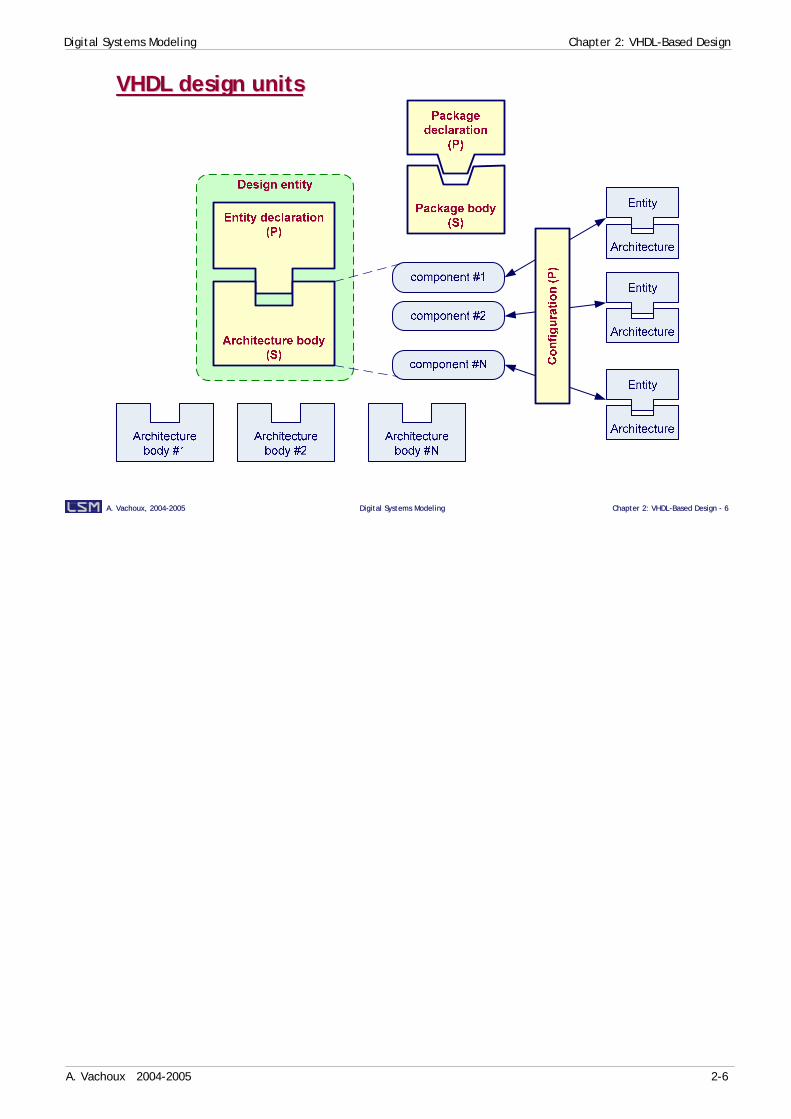
♦ Modularity• 5 design entities: entity, architecture, package declaration and body,
configuration• Separation of interface from implementation• Separate compilation
♦ Strong typing• Every object has a type• Type compatibility checked at compile time
♦ Extensibility: User-defined types
♦ Model of time• Discrete time, integer multiple of some MRT (Minimum Resolvable Time)
♦ Event-driven simulation semantics

Digital Systems Modeling Chapter 2: VHDL-Based Design
A. Vachoux 2004-2005 2-5
A. Vachoux, 2004A. Vachoux, 2004--20052005 Digital Systems ModelingDigital Systems Modeling Chapter 2: VHDLChapter 2: VHDL--Based Design Based Design -- 55
VHDLVHDL--basedbased design design flowflow
RTL model
Editor(text or graphic)
Test bench models
Logic/RTL synthesis
Logicsimulation
VHDL packages
Constraints(area, timing, power)
Standard celllibrary
VHDL VITALstandard cell
modeldGate-level
netlist
Place & route
LayoutDelay extraction
SDF file
The VHDL-based design flow starts from a description of the system as a RTL model. Complex behavior is described as finite state machines or Boolean equations. The RTL model may use external declarations from standard or user-defined packages. The RTL model can be written using a text editor or using a graphical editor supporting flow charts, finite state machines or dataflow representations.The RTL model can be validated through logic simulation using a VHDL test bench. The test bench declares the design entity to test and stimulus to apply to the unit under test. System functions can then be validated before any realization is actually available.The RTL model can then be synthesized using a logic synthesizer. The tool is able to derive an optimized gate-level netlist using logic gates from a standard cell library. The optimization is driven by user-defined constraints on area, timings and/or power consumption. The constraints are not included in the VHDL model, but specified separately in the synthesis tool environment. The standard cell library includes information on all the available cells in some technological process (e.g. 0.35µ CMOS): logic functions, areas, timing delays, power consumption. The library format is tool dependent.The gate-level netlist can be described in many forms depending on what to do next. A VHDL version of it is usually used for logic simulation. VHDL models of standard cells are provided by the technology provider (foundry or FPGA vendor) in the form of VITAL models. VITAL is an IEEE standard that defines how VHDL models of cells must be written to allow interoperability between different simulation environments. The logic simulation of gate-level netlists now takes care of cell delays and possibly estimated interconnect delays.The generation of layout is done with a place and route tool that usually requires a description of the gate-level netlist in a different form (e.g. in Verilog, EDIF or XNF). As layout includes true geometrical information, it is possible to extract the values of parasitic R and C elements from wire shapes and to compute timing delays. These delays are stored in the SDF (Standard Delay Format) format and can be back-annotated in VITAL VHDL models of the standard cells. Logic simulation can now take care of more realistic interconnect delays and can be accurate enough to avoid the need to do time consuming circuit-level (SPICE) simulations.
Digital Systems Modeling Chapter 2: VHDL-Based Design
A. Vachoux 2004-2005 2-6
A. Vachoux, 2004A. Vachoux, 2004--20052005 Digital Systems ModelingDigital Systems Modeling Chapter 2: VHDLChapter 2: VHDL--Based Design Based Design -- 66
VHDL design unitsVHDL design units
Digital Systems Modeling Chapter 2: VHDL-Based Design
A. Vachoux 2004-2005 2-7
A. Vachoux, 2004A. Vachoux, 2004--20052005 Digital Systems ModelingDigital Systems Modeling Chapter 2: VHDLChapter 2: VHDL--Based Design Based Design -- 77
Design entityDesign entity
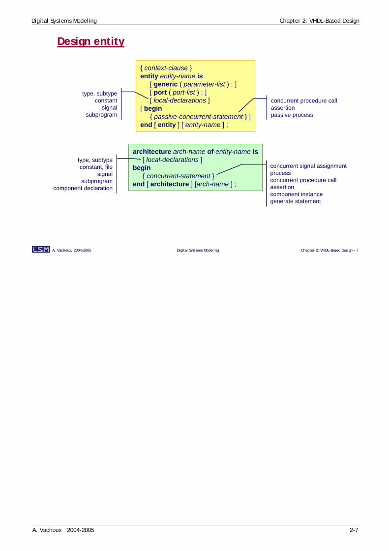
{ context-clause }entity entity-name is
[ generic ( parameter-list ) ; ][ port ( port-list ) ; ][ local-declarations ]
[ begin{ passive-concurrent-statement } ]
end [ entity ] [ entity-name ] ;
architecture arch-name of entity-name is[ local-declarations ]
begin{ concurrent-statement }
end [ architecture ] [arch-name ] ;
type, subtypeconstant
signalsubprogram
concurrent procedure callassertionpassive process
type, subtypeconstant, file
signalsubprogram
component declaration
concurrent signal assignmentprocessconcurrent procedure callassertioncomponent instancegenerate statement
Digital Systems Modeling Chapter 2: VHDL-Based Design
A. Vachoux 2004-2005 2-8
A. Vachoux, 2004A. Vachoux, 2004--20052005 Digital Systems ModelingDigital Systems Modeling Chapter 2: VHDLChapter 2: VHDL--Based Design Based Design -- 88
Design librariesDesign libraries
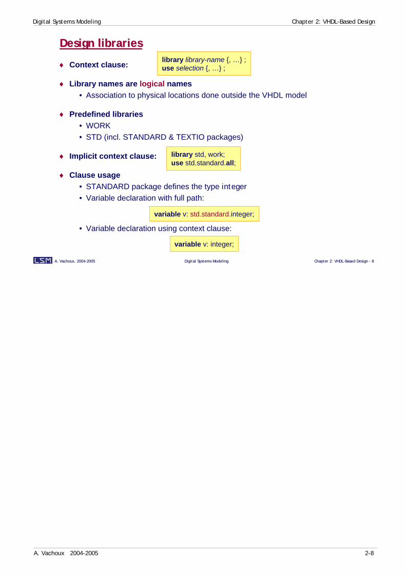
♦ Context clause:
♦ Library names are logical names• Association to physical locations done outside the VHDL model
♦ Predefined libraries• WORK• STD (incl. STANDARD & TEXTIO packages)
♦ Implicit context clause:
♦ Clause usage• STANDARD package defines the type integer• Variable declaration with full path:
• Variable declaration using context clause:
library library-name {, …} ;use selection {, …} ;
library std, work;use std.standard.all;
variable v: std.standard.integer;
variable v: integer;

Digital Systems Modeling Chapter 2: VHDL-Based Design
A. Vachoux 2004-2005 2-9
A. Vachoux, 2004A. Vachoux, 2004--20052005 Digital Systems ModelingDigital Systems Modeling Chapter 2: VHDLChapter 2: VHDL--Based Design Based Design -- 99
Entity declarationEntity declaration
entity entity-name is[ generic ( parameter-list ) ; ][ port ( port-list ) ; ][ local-declarations ]
[ begin{ passive-concurrent-statement } ]
end [ entity ] [ entity-name ] ;
generic (param-name {, …} : param-type [ := default-value ] ;…param-name {, …} : param-type [ := default-value ] ) ;
port ([ signal ] signal-name {, …} : mode signal-type ;…[ signal ] signal-name {, …} : mode signal-type ) ;
♦ Example: 1-bit full adder
entity add1 isgeneric (
TP: time := 0 ns); -- propagation timeport (
signal opa, opb, cin: in bit; -- input operands & carrysignal sum, cout: out bit); -- output sum & carry
end entity add1;
Digital Systems Modeling Chapter 2: VHDL-Based Design
A. Vachoux 2004-2005 2-10
A. Vachoux, 2004A. Vachoux, 2004--20052005 Digital Systems ModelingDigital Systems Modeling Chapter 2: VHDLChapter 2: VHDL--Based Design Based Design -- 1010
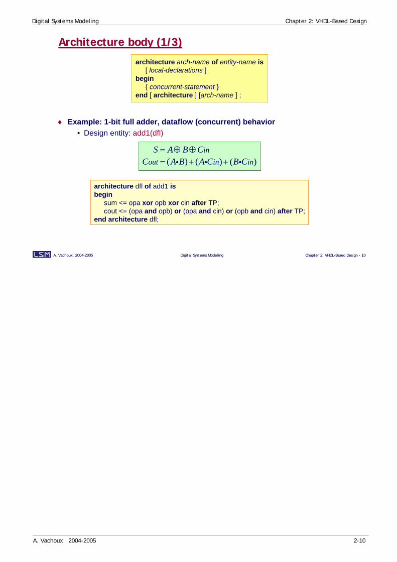
Architecture body (1/3)Architecture body (1/3)
♦ Example: 1-bit full adder, dataflow (concurrent) behavior• Design entity: add1(dfl)
architecture arch-name of entity-name is[ local-declarations ]
begin{ concurrent-statement }
end [ architecture ] [arch-name ] ;
( ) ( ) ( )in
out in inS A B C
C A B A C B C= ⊕ ⊕= + +i i i
architecture dfl of add1 isbegin
sum <= opa xor opb xor cin after TP;cout <= (opa and opb) or (opa and cin) or (opb and cin) after TP;
end architecture dfl;

Digital Systems Modeling Chapter 2: VHDL-Based Design
A. Vachoux 2004-2005 2-11
A. Vachoux, 2004A. Vachoux, 2004--20052005 Digital Systems ModelingDigital Systems Modeling Chapter 2: VHDLChapter 2: VHDL--Based Design Based Design -- 1111
Architecture body (2/3)Architecture body (2/3)
♦ Example: 1-bit full adder, sequential behavior• Design entity: add1(algo)
architecture algo of add1 isbegin
process (opa, opb, cin)variable tmp: integer;
begintmp := 0;if opa = '1' then tmp := tmp + 1; end if;if opb = '1' then tmp := tmp + 1; end if;if cin = '1' then tmp := tmp + 1; end if;if tmp > 1 then cout <= '1' after TP;
else cout <= '0' after TP; end if;if tmp mod 2 = 0 then sum <= '0' after TP;
else sum <= '1' after TP; end if;end process;
end architecture algo;
opa opb cin
process
sum cout

Digital Systems Modeling Chapter 2: VHDL-Based Design
A. Vachoux 2004-2005 2-12
A. Vachoux, 2004A. Vachoux, 2004--20052005 Digital Systems ModelingDigital Systems Modeling Chapter 2: VHDLChapter 2: VHDL--Based Design Based Design -- 1212
Architecture body (3/3)Architecture body (3/3)
♦ Example: 1-bit full adder, structural model• Design entity: add1(str)• Direct instantiation
library gates;architecture str of add1 is
signal s1, s2, s3, s4: bit;begin
A1: entity gates.and2d1(dfl)generic map (TPR => TP)port map (i1 => opa, i2 => opb, o => s1);
A2: entity gates.and2d1(dfl)generic map (TPR => TP)port map (i1 => s2, i2 => cin, o => s3);
O1: entity gates.or2d1(dfl)generic map (TP)port map (opa, opb, s2);
O2: entity gates.or2d1(dfl)generic map (TP)port map (s3, s1, cout);
X1: entity gates.ex2d1(dfl)generic map (TPR => TP)port map (o => s4, i1 => opa, i2 => opb);
X2: entity gates.ex2d1(dfl)generic map (TP)port map (s4, cin, sum);
end architecture str;
Digital Systems Modeling Chapter 2: VHDL-Based Design
A. Vachoux 2004-2005 2-13
A. Vachoux, 2004A. Vachoux, 2004--20052005 Digital Systems ModelingDigital Systems Modeling Chapter 2: VHDLChapter 2: VHDL--Based Design Based Design -- 1313
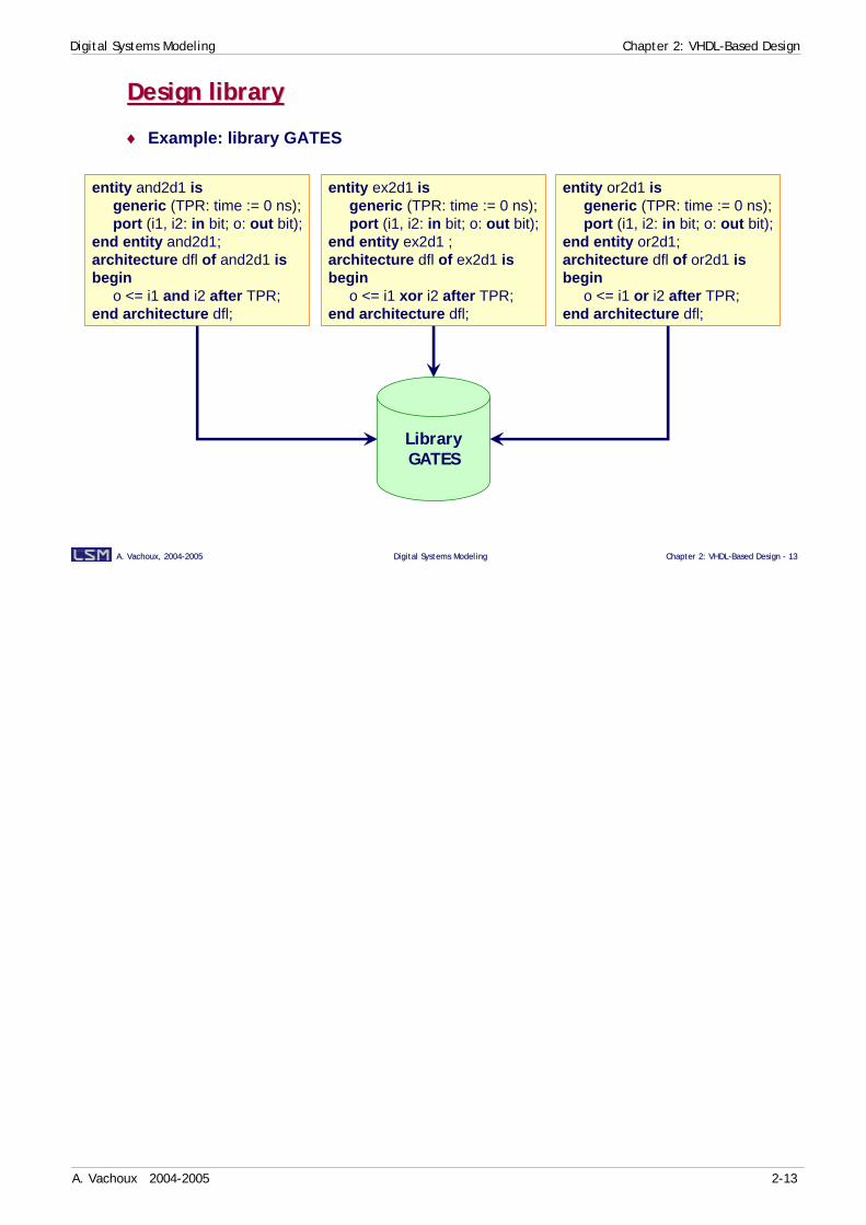
Design libraryDesign library
♦ Example: library GATES
entity and2d1 isgeneric (TPR: time := 0 ns);port (i1, i2: in bit; o: out bit);
end entity and2d1;architecture dfl of and2d1 isbegin
o <= i1 and i2 after TPR;end architecture dfl;
entity ex2d1 isgeneric (TPR: time := 0 ns);port (i1, i2: in bit; o: out bit);
end entity ex2d1 ;architecture dfl of ex2d1 isbegin
o <= i1 xor i2 after TPR;end architecture dfl;
entity or2d1 isgeneric (TPR: time := 0 ns);port (i1, i2: in bit; o: out bit);
end entity or2d1;architecture dfl of or2d1 isbegin
o <= i1 or i2 after TPR;end architecture dfl;
LibraryGATES
Digital Systems Modeling Chapter 2: VHDL-Based Design
A. Vachoux 2004-2005 2-14
A. Vachoux, 2004A. Vachoux, 2004--20052005 Digital Systems ModelingDigital Systems Modeling Chapter 2: VHDLChapter 2: VHDL--Based Design Based Design -- 1414
TestbenchTestbench
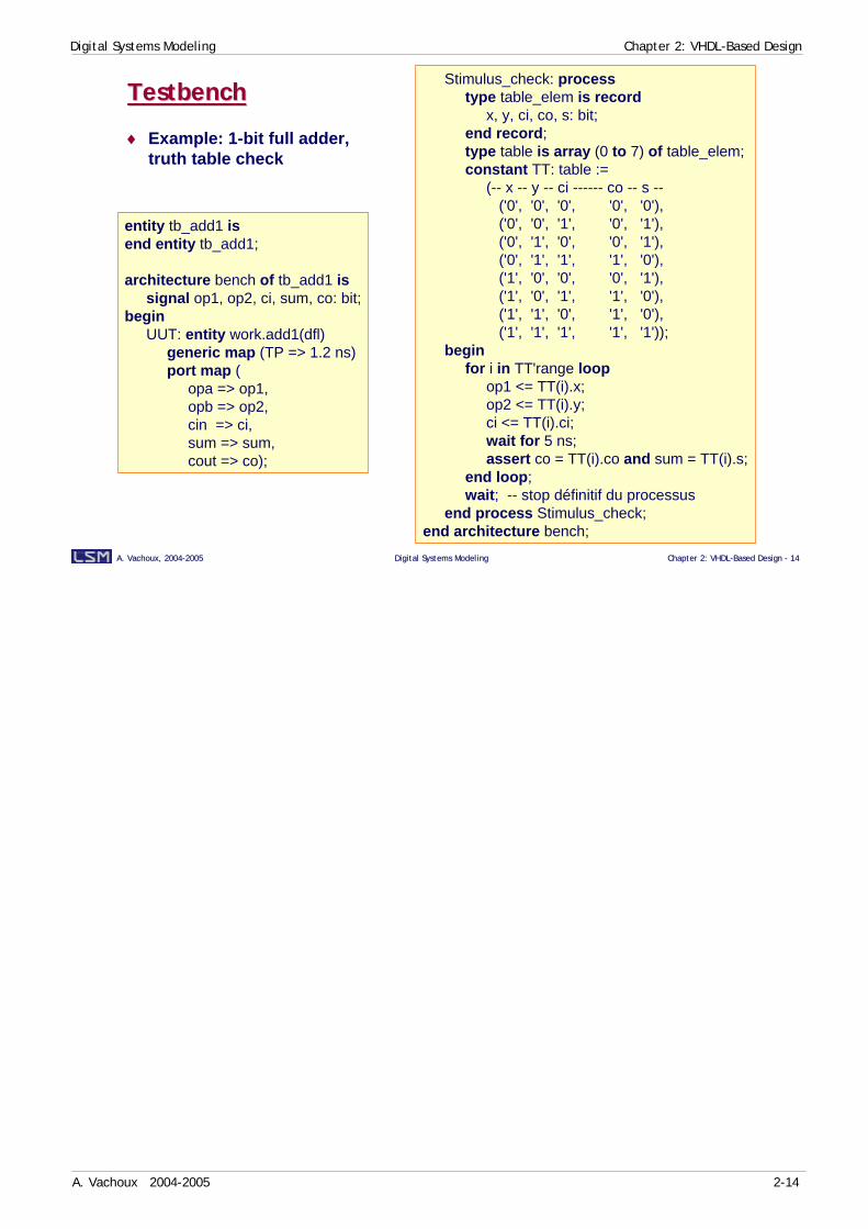
♦ Example: 1-bit full adder,truth table check
entity tb_add1 isend entity tb_add1;
architecture bench of tb_add1 issignal op1, op2, ci, sum, co: bit;
beginUUT: entity work.add1(dfl)
generic map (TP => 1.2 ns)port map (
opa => op1,opb => op2,cin => ci,sum => sum,cout => co);
Stimulus_check: processtype table_elem is record
x, y, ci, co, s: bit;end record;type table is array (0 to 7) of table_elem;constant TT: table :=
(-- x -- y -- ci ------ co -- s --('0', '0', '0', '0', '0'),('0', '0', '1', '0', '1'),('0', '1', '0', '0', '1'),('0', '1', '1', '1', '0'),('1', '0', '0', '0', '1'),('1', '0', '1', '1', '0'),('1', '1', '0', '1', '0'),('1', '1', '1', '1', '1'));
beginfor i in TT'range loop
op1 <= TT(i).x;op2 <= TT(i).y;ci <= TT(i).ci;wait for 5 ns;assert co = TT(i).co and sum = TT(i).s;
end loop;wait; -- stop définitif du processus
end process Stimulus_check;end architecture bench;

Digital Systems Modeling Chapter 2: VHDL-Based Design
A. Vachoux 2004-2005 2-15
A. Vachoux, 2004A. Vachoux, 2004--20052005 Digital Systems ModelingDigital Systems Modeling Chapter 2: VHDLChapter 2: VHDL--Based Design Based Design -- 1515
SignalsSignals
♦ Signal declaration:
♦ Examples:
♦ Signal driver:
signal signal-name {, ... } : type [ := expression ] ;
signal S: bit_vector(15 downto 0); -- default initial value = (others => ’0’)signal CLK: bit := ’1’; -- explicit initial valuesignal reset, strobe, enable: boolean; -- default initial value = FALSE
vcvc+1
tc+1
vc+2
tc+2
vc+3
tc+3current
value
transactions
Digital Systems Modeling Chapter 2: VHDL-Based Design
A. Vachoux 2004-2005 2-16
A. Vachoux, 2004A. Vachoux, 2004--20052005 Digital Systems ModelingDigital Systems Modeling Chapter 2: VHDLChapter 2: VHDL--Based Design Based Design -- 1616
Process statementProcess statement
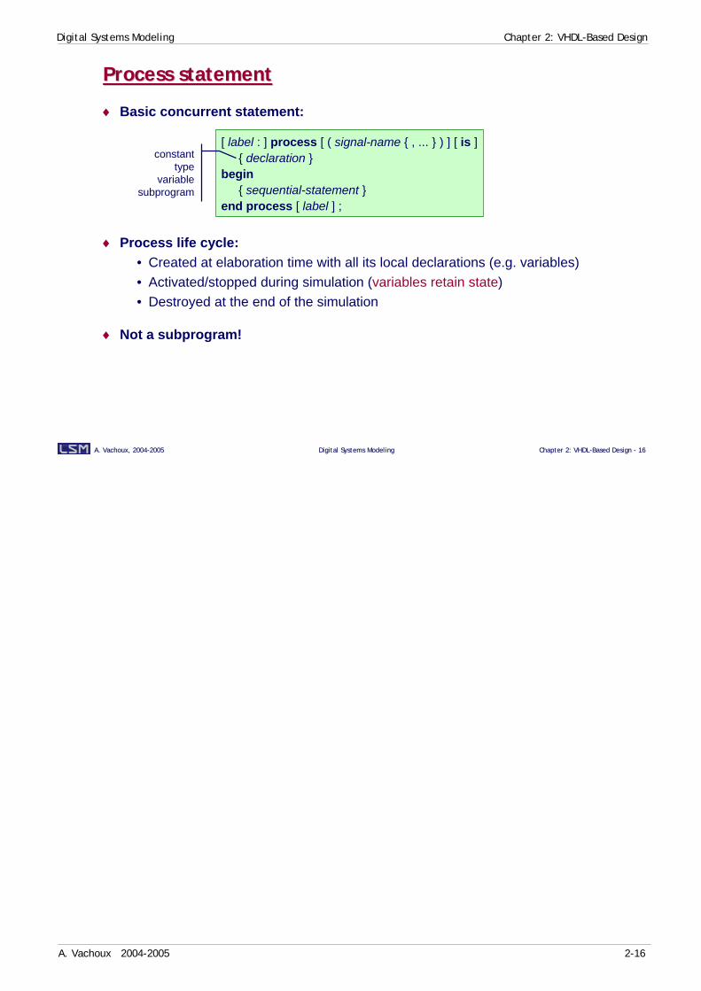
♦ Basic concurrent statement:
♦ Process life cycle:• Created at elaboration time with all its local declarations (e.g. variables)• Activated/stopped during simulation (variables retain state)• Destroyed at the end of the simulation
♦ Not a subprogram!
[ label : ] process [ ( signal-name { , ... } ) ] [ is ]{ declaration }
begin{ sequential-statement }
end process [ label ] ;
constanttype
variablesubprogram

Digital Systems Modeling Chapter 2: VHDL-Based Design
A. Vachoux 2004-2005 2-17
A. Vachoux, 2004A. Vachoux, 2004--20052005 Digital Systems ModelingDigital Systems Modeling Chapter 2: VHDLChapter 2: VHDL--Based Design Based Design -- 1717
Process activation controlProcess activation control
♦ Either through a sensitivity list:
♦ Or through wait statements:
process (S1, S2, …)begin
sequential statementsend process; -- equivalent to sensitivity list
processbegin
sequential statementswait on S1, S2;
end process;
wait for 10 ns;processbegin
…wait …;…
end process;
wait on S1, S2, S3;
wait until clk = '1';wait on clk until clk = '1'; -- equivalent to previous onewait on reset until clk = '1'; -- not sensitive to an event on clk
wait;wait until next_event; -- with variable next_event: boolean;
wait on S1, S2 until en = '1' for 15 ns;
Digital Systems Modeling Chapter 2: VHDL-Based Design
A. Vachoux 2004-2005 2-18
A. Vachoux, 2004A. Vachoux, 2004--20052005 Digital Systems ModelingDigital Systems Modeling Chapter 2: VHDLChapter 2: VHDL--Based Design Based Design -- 1818
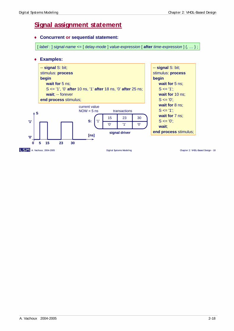
Signal assignment statementSignal assignment statement
♦ Concurrent or sequential statement:
♦ Examples:
[ label : ] signal-name <= [ delay-mode ] value-expression [ after time-expression ] {, … } ;
-- signal S: bit;stimulus: processbegin
wait for 5 ns;S <= ’1’, ’0’ after 10 ns, ’1’ after 18 ns, ’0’ after 25 ns;wait; -- forever
end process stimulus;
-- signal S: bit;stimulus: processbegin
wait for 5 ns;S <= '1';wait for 10 ns;S <= '0';wait for 8 ns;S <= '1';wait for 7 ns;S <= '0';wait;
end process stimulus;[ns]
50 15 23 30'0'
'1'
S
S:15
'1''0' '1' '0'
23 30
signal driver
current valueNOW = 5 ns transactions

Digital Systems Modeling Chapter 2: VHDL-Based Design
A. Vachoux 2004-2005 2-19
A. Vachoux, 2004A. Vachoux, 2004--20052005 Digital Systems ModelingDigital Systems Modeling Chapter 2: VHDLChapter 2: VHDL--Based Design Based Design -- 1919
Delay modesDelay modes
inv1: process (A) isbegin
Y1 <= not A after 5 ns;-- Y1 <= inertial not A after 5 ns;
Y2 <= reject 2 ns inertial not A after 5 ns;end process inv1;
inv2: process (A) isbegin
Y3 <= transport not A after 5 ns;Y4 <= reject 0 ns inertial not A after 5 ns;
end process inv2;

Digital Systems Modeling Chapter 2: VHDL-Based Design
A. Vachoux 2004-2005 2-20
A. Vachoux, 2004A. Vachoux, 2004--20052005 Digital Systems ModelingDigital Systems Modeling Chapter 2: VHDLChapter 2: VHDL--Based Design Based Design -- 2020
Process examplesProcess examples
entity latch isport (en, d: in bit; q: out bit);
end entity latch;
architecture bhv of latch isbegin
process (en, d)begin
if en = '1' thenq <= d;
end if;end process;
end architecture bhv;
♦ Latch
-- signal A, B, Q: bit;MullerC: processbegin
wait until A = '1' and B = '1';Q <= '1';wait until A = '0' and B = '0';Q <= '0';
end process MullerC;
♦ Asynchronous element
entity dff isport (clk, d: in bit; q: out bit);
end entity dff;
architecture bhv of dff isbegin
processbegin
wait until clk = '1';q <= d;
end process;end architecture bhv;
♦ Flip-flop
-- signal clk: bit := ’0’;clk_gen: process (clk)begin
clk <= not clk after 5 ns; -- 100 MHzend process clk_gen;
♦ Clock generator
Digital Systems Modeling Chapter 2: VHDL-Based Design
A. Vachoux 2004-2005 2-21
A. Vachoux, 2004A. Vachoux, 2004--20052005 Digital Systems ModelingDigital Systems Modeling Chapter 2: VHDLChapter 2: VHDL--Based Design Based Design -- 2121
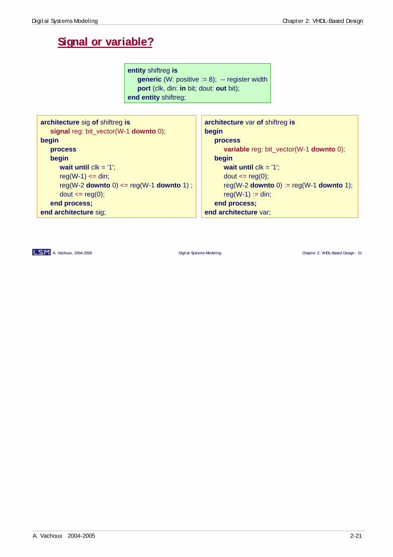
Signal or variable?Signal or variable?
entity shiftreg isgeneric (W: positive := 8); -- register widthport (clk, din: in bit; dout: out bit);
end entity shiftreg;
architecture sig of shiftreg issignal reg: bit_vector(W-1 downto 0);
beginprocessbegin
wait until clk = '1';reg(W-1) <= din;reg(W-2 downto 0) <= reg(W-1 downto 1) ;dout <= reg(0);
end process;end architecture sig;
architecture var of shiftreg isbegin
processvariable reg: bit_vector(W-1 downto 0);
beginwait until clk = '1';dout <= reg(0);reg(W-2 downto 0) := reg(W-1 downto 1); reg(W-1) := din;
end process;end architecture var;
Digital Systems Modeling Chapter 2: VHDL-Based Design
A. Vachoux 2004-2005 2-22
A. Vachoux, 2004A. Vachoux, 2004--20052005 Digital Systems ModelingDigital Systems Modeling Chapter 2: VHDLChapter 2: VHDL--Based Design Based Design -- 2222
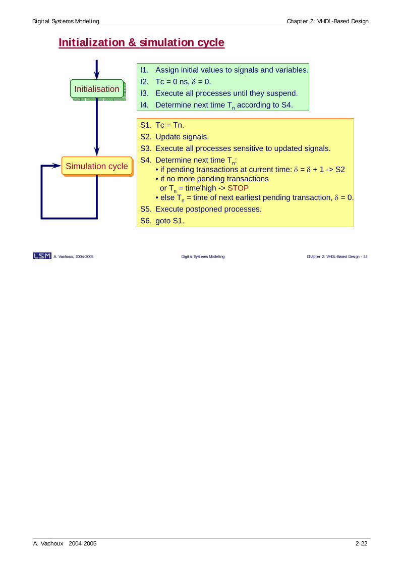
Initialization & simulation cycleInitialization & simulation cycle
I1. Assign initial values to signals and variables.I2. Tc = 0 ns, δ = 0.I3. Execute all processes until they suspend.I4. Determine next time Tn according to S4.
S1. Tc = Tn.S2. Update signals.S3. Execute all processes sensitive to updated signals.S4. Determine next time Tn:
• if pending transactions at current time: δ = δ + 1 -> S2• if no more pending transactions
or Tn = time'high -> STOP• else Tn = time of next earliest pending transaction, δ = 0.
S5. Execute postponed processes.S6. goto S1.
InitialisationInitialisation
Simulation cycleSimulation cycle
Digital Systems Modeling Chapter 2: VHDL-Based Design
A. Vachoux 2004-2005 2-23
A. Vachoux, 2004A. Vachoux, 2004--20052005 Digital Systems ModelingDigital Systems Modeling Chapter 2: VHDLChapter 2: VHDL--Based Design Based Design -- 2323
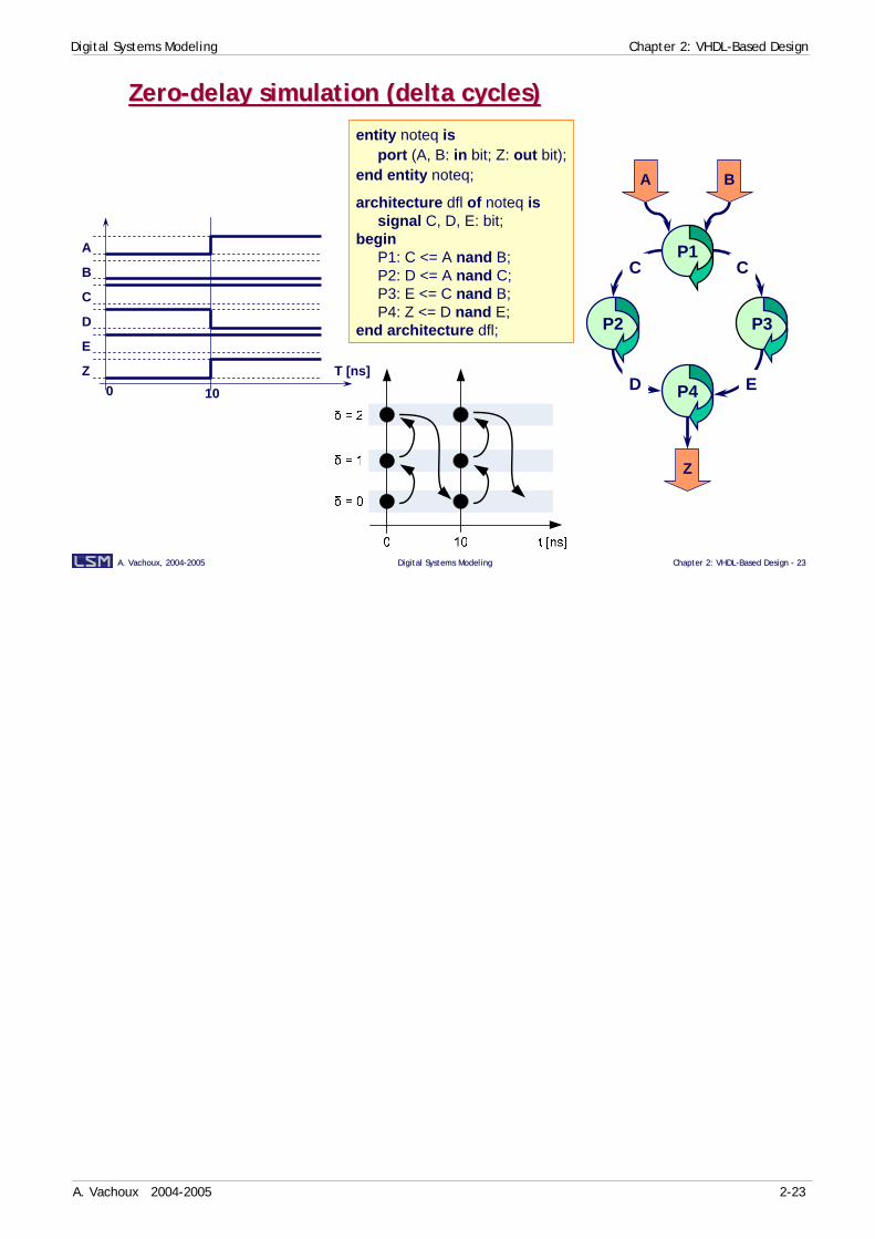
ZeroZero--delay simulation (delta cycles)delay simulation (delta cycles)
Z
P2 P3
P4
A B
C C
D E
P1
entity noteq isport (A, B: in bit; Z: out bit);
end entity noteq;
architecture dfl of noteq issignal C, D, E: bit;
beginP1: C <= A nand B;P2: D <= A nand C;P3: E <= C nand B;P4: Z <= D nand E;
end architecture dfl;
10T [ns]
A
B
C
D
E
Z0

Digital Systems Modeling Chapter 2: VHDL-Based Design
A. Vachoux 2004-2005 2-24
A. Vachoux, 2004A. Vachoux, 2004--20052005 Digital Systems ModelingDigital Systems Modeling Chapter 2: VHDLChapter 2: VHDL--Based Design Based Design -- 2424
Resolution functionResolution function
architecture A of E issignal S: logic4;
beginP1: process begin
wait for 10 ns;S <= ’1’;wait for 20 ns;S <= ’0’;
end process P1;P2: process begin
wait for 20 ns;S <= ’0’;wait for 20 ns;S <= ’1’;
end process P2;end architecture A;
P1_S driver
P2_S driver
resolutionresolutionfunctionfunction resolved signal S
'0'
'1'
'X'
-- unresolved typestype ulogic4 is (’X’, ’0’, ’1’, ’Z’); type ulogic4_vector is array (natural range <>) of ulogic4;-- resolved typessubtype logic4 is resolve ulogic4;type logic4_vector is array (natural range <>) of logic4;
Digital Systems Modeling Chapter 2: VHDL-Based Design
A. Vachoux 2004-2005 2-25
A. Vachoux, 2004A. Vachoux, 2004--20052005 Digital Systems ModelingDigital Systems Modeling Chapter 2: VHDLChapter 2: VHDL--Based Design Based Design -- 2525
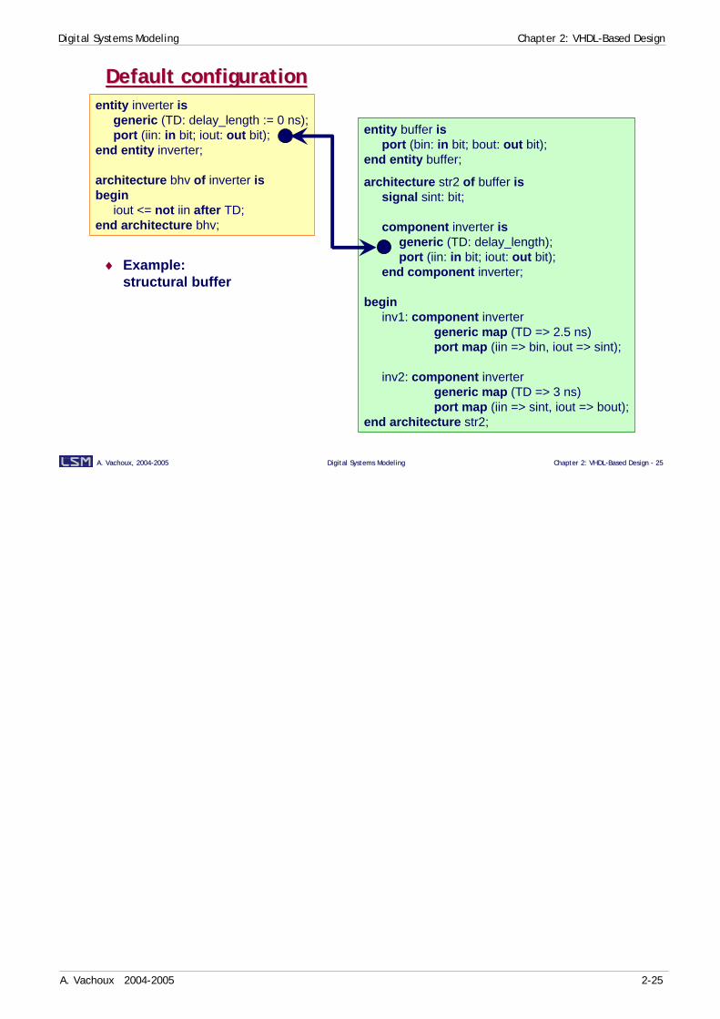
entity buffer isport (bin: in bit; bout: out bit);
end entity buffer;
architecture str2 of buffer issignal sint: bit;
component inverter isgeneric (TD: delay_length);port (iin: in bit; iout: out bit);
end component inverter;
begininv1: component inverter
generic map (TD => 2.5 ns)port map (iin => bin, iout => sint);
inv2: component invertergeneric map (TD => 3 ns)port map (iin => sint, iout => bout);
end architecture str2;
Default configurationDefault configurationentity inverter is
generic (TD: delay_length := 0 ns);port (iin: in bit; iout: out bit);
end entity inverter;
architecture bhv of inverter isbegin
iout <= not iin after TD;end architecture bhv;
♦ Example:structural buffer
Digital Systems Modeling Chapter 2: VHDL-Based Design
A. Vachoux 2004-2005 2-26
A. Vachoux, 2004A. Vachoux, 2004--20052005 Digital Systems ModelingDigital Systems Modeling Chapter 2: VHDLChapter 2: VHDL--Based Design Based Design -- 2626
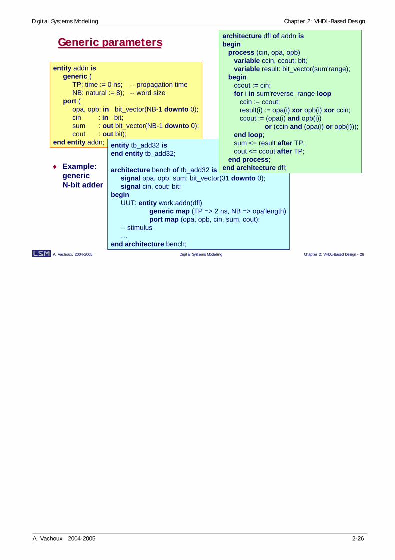
Generic parametersGeneric parameters
entity addn isgeneric (
TP: time := 0 ns; -- propagation timeNB: natural := 8); -- word size
port (opa, opb: in bit_vector(NB-1 downto 0);cin : in bit;sum : out bit_vector(NB-1 downto 0);cout : out bit);
end entity addn;
♦ Example:genericN-bit adder
entity tb_add32 isend entity tb_add32;
architecture bench of tb_add32 issignal opa, opb, sum: bit_vector(31 downto 0);signal cin, cout: bit;
beginUUT: entity work.addn(dfl)
generic map (TP => 2 ns, NB => opa'length)port map (opa, opb, cin, sum, cout);
-- stimulus…
end architecture bench;
architecture dfl of addn isbegin
process (cin, opa, opb)variable ccin, ccout: bit;variable result: bit_vector(sum'range);
beginccout := cin;for i in sum'reverse_range loop
ccin := ccout;result(i) := opa(i) xor opb(i) xor ccin;ccout := (opa(i) and opb(i))
or (ccin and (opa(i) or opb(i)));end loop;sum <= result after TP;cout <= ccout after TP;
end process;end architecture dfl;
Digital Systems Modeling Chapter 2: VHDL-Based Design
A. Vachoux 2004-2005 2-27
A. Vachoux, 2004A. Vachoux, 2004--20052005 Digital Systems ModelingDigital Systems Modeling Chapter 2: VHDLChapter 2: VHDL--Based Design Based Design -- 2727
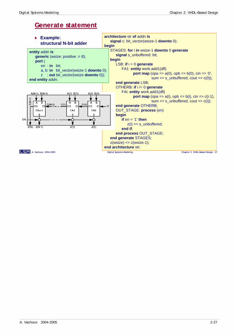
Generate statementGenerate statement
architecture str of addn issignal c: bit_vector(wsize-1 downto 0);
beginSTAGES: for i in wsize-1 downto 0 generate
signal s_unbuffered: bit;begin
LSB: if i = 0 generateFA1: entity work.add1(dfl)
port map (opa => a(0), opb => b(0), cin => ’0’,sum => s_unbuffered, cout => c(0));
end generate LSB;OTHERB: if i /= 0 generate
FAi: entity work.add1(dfl)port map (opa => a(i), opb => b(i), cin => c(i-1),
sum => s_unbuffered, cout => c(i));end generate OTHERB;OUT_STAGE: process (en)begin
if en = ’1’ thenz(i) <= s_unbuffered;
end if;end process OUT_STAGE;
end generate STAGES;z(wsize) <= c(wsize-1);
end architecture str;
entity addn isgeneric (wsize: positive := 8);port (
en : in bit;a, b: in bit_vector(wsize-1 downto 0);z : out bit_vector(wsize downto 0));
end entity addn;
♦ Example:structural N-bit adder
Digital Systems Modeling Chapter 2: VHDL-Based Design
A. Vachoux 2004-2005 2-28
A. Vachoux, 2004A. Vachoux, 2004--20052005 Digital Systems ModelingDigital Systems Modeling Chapter 2: VHDLChapter 2: VHDL--Based Design Based Design -- 2828
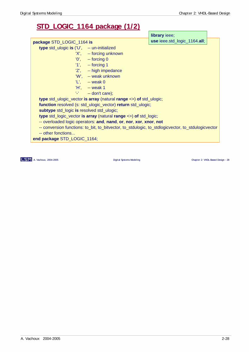
STD_LOGIC_1164 package (1/2)STD_LOGIC_1164 package (1/2)
package STD_LOGIC_1164 istype std_ulogic is (’U’, -- un-initialized
’X’, -- forcing unknown’0’, -- forcing 0’1’, -- forcing 1’Z’, -- high impedance’W’, -- weak unknown’L’, -- weak 0’H’, -- weak 1’-’ -- don't care);
type std_ulogic_vector is array (natural range <>) of std_ulogic;function resolved (s: std_ulogic_vector) return std_ulogic;subtype std_logic is resolved std_ulogic;type std_logic_vector is array (natural range <>) of std_logic;-- overloaded logic operators: and, nand, or, nor, xor, xnor, not-- conversion functions: to_bit, to_bitvector, to_stdulogic, to_stdlogicvector, to_stdulogicvector-- other fonctions...
end package STD_LOGIC_1164;
library ieee;use ieee.std_logic_1164.all;

Digital Systems Modeling Chapter 2: VHDL-Based Design
A. Vachoux 2004-2005 2-29
A. Vachoux, 2004A. Vachoux, 2004--20052005 Digital Systems ModelingDigital Systems Modeling Chapter 2: VHDLChapter 2: VHDL--Based Design Based Design -- 2929
STD_LOGIC_1164 package (2/2)STD_LOGIC_1164 package (2/2)package body STD_LOGIC_1164 is
...type stdlogic_table is
array (std_ulogic, std_ulogic) of std_ulogic;constant resolution_table : stdlogic_table := (
--| U X 0 1 Z W L H - |(’U’, ’U’, ’U’, ’U’, ’U’, ’U’, ’U’, ’U’, ’U’), -- | U |(’U’, ’X’, ’X’, ’X’, ’X’, ’X’, ’X’, ’X’, ’X’), -- | X |(’U’, ’X’, ’0’, ’X’, ’0’, ’0’, ’0’, ’0’, ’X’), -- | 0 |(’U’, ’X’, ’X’, ’1’, ’1’, ’1’, ’1’, ’1’, ’X’), -- | 1 |(’U’, ’X’, ’0’, ’1’, ’Z’, ’W’, ’L’, ’H’, ’X’), -- | Z |(’U’, ’X’, ’0’, ’1’, ’W’, ’W’, ’W’, ’W’, ’X’), -- | W |(’U’, ’X’, ’0’, ’1’, ’L’, ’W’, ’L’, ’W’, ’X’), -- | L |(’U’, ’X’, ’0’, ’1’, ’H’, ’W’, ’W’, ’H’, ’X’), -- | H |(’U’, ’X’, ’X’, ’X’, ’X’, ’X’, ’X’, ’X’, ’X’) -- | - |);
…
...function resolved (s : std_ulogic_vector) return std_ulogic is
variable result : std_ulogic := 'Z'; -- default statebegin
if s'length = 1 then return s(s'low); -- single driver caseelse
for i in s'range loopresult := resolution_table(result, s(i));
end loop;end if;return result;
end function resolved;...
end package body STD_LOGIC_1164;
Digital Systems Modeling Chapter 2: VHDL-Based Design
A. Vachoux 2004-2005 2-30
A. Vachoux, 2004A. Vachoux, 2004--20052005 Digital Systems ModelingDigital Systems Modeling Chapter 2: VHDLChapter 2: VHDL--Based Design Based Design -- 3030
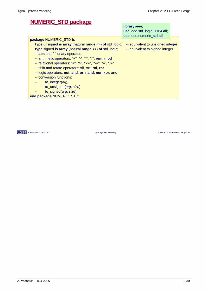
NUMERIC_STD packageNUMERIC_STD package
package NUMERIC_STD istype unsigned is array (natural range <>) of std_logic; -- equivalent to unsigned integertype signed is array (natural range <>) of std_logic; -- equivalent to signed integer-- abs and "-" unary operators-- arithmetic operators: "+", "-", "*", "/", rem, mod-- relational operators: "<", ">", "<=", ">=", "=", "/="-- shift and rotate operators: sll, srl, rol, ror-- logic operators: not, and, or, nand, nor, xor, xnor-- conversion functions:-- to_integer(arg)-- to_unsigned(arg, size)-- to_signed(arg, size)
end package NUMERIC_STD;
library ieee;use ieee.std_logic_1164.all;use ieee.numeric_std.all;
Digital Systems Modeling Chapter 2: VHDL-Based Design
A. Vachoux 2004-2005 2-31
A. Vachoux, 2004A. Vachoux, 2004--20052005 Digital Systems ModelingDigital Systems Modeling Chapter 2: VHDLChapter 2: VHDL--Based Design Based Design -- 3131
VHDL for synthesisVHDL for synthesis
♦ Language subset• All legal VHDL constructs do not have a meaning for synthesis
♦ Modeling subset• Synthesis tools recognize specific code templates to infer hardware
♦ 3 IEEE standards:• IEEE 1164: 9-state logic type std(u)_logic(_vector) + logic operators• IEEE 1076.3: unsigned and signed types + logic and arith operators• IEEE 1076.6: synthesis semantics

Digital Systems Modeling Chapter 2: VHDL-Based Design
A. Vachoux 2004-2005 2-32
A. Vachoux, 2004A. Vachoux, 2004--20052005 Digital Systems ModelingDigital Systems Modeling Chapter 2: VHDLChapter 2: VHDL--Based Design Based Design -- 3232
Supported types: enumerated typesSupported types: enumerated types
♦ Types: bit boolean character std_(u)logic
♦ Default encoding:
♦ Specific encoding, e.g. one-hot:
♦ std_(u)logic (in ieee.std_logic_1164)• Interpreted as 1 bit• '0', 'L': low logic level• '1', 'H': high logic level• 'U', 'X', 'W', '-': metalogical states (ignored)• 'Z': high-impedance
type state is (idle, init, shift, add, check);-- encodage: "000" "001" "010" "011" "100"
attribute enum_encoding: string;attribute enum_encoding of state: type is "00001 00010 00100 01000 10000";-- idle init shift add check
if enable = '1' thenrequest <= ready;
elserequest <= 'Z';
end if;
library synopsys;use synopsys.attributes.all;
Predefined types bit and boolean are interpreted as single bits. Other enumerated types are encoded. Default encoding is binary encoding with enough bits to represent all enumerated states.
When default encoding is not appropriate (e.g. in finite state machine models), it is possible to use a VHDL attribute declaration do annotate each state with its related encoding word. The VHDL attribute enum_encodingis not predefined and is available in a tool dependent package.The "one-hot" encoding example shows the 5-bit words defined in a string in the order in which the enumerated states are declared.
The logic types std_ulogic and std_logic, defined in the STD_LOGIC_1164 standard package, have a specific interpretation for synthesis. Even if they formally have 9 states, they are interpreted in hardware as a single bit. The use of the 'Z' state allows to infer tri-state buffers.
Digital Systems Modeling Chapter 2: VHDL-Based Design
A. Vachoux 2004-2005 2-33
A. Vachoux, 2004A. Vachoux, 2004--20052005 Digital Systems ModelingDigital Systems Modeling Chapter 2: VHDLChapter 2: VHDL--Based Design Based Design -- 3333
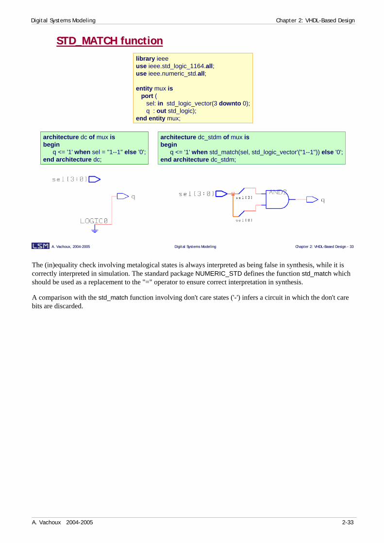
STD_MATCH functionSTD_MATCH functionlibrary ieeeuse ieee.std_logic_1164.all;use ieee.numeric_std.all;
entity mux isport (
sel: in std_logic_vector(3 downto 0);q : out std_logic);
end entity mux;
architecture dc_stdm of mux isbegin
q <= '1' when std_match(sel, std_logic_vector'("1--1")) else '0';end architecture dc_stdm;
architecture dc of mux isbegin
q <= '1' when sel = "1--1" else '0';end architecture dc;
The (in)equality check involving metalogical states is always interpreted as being false in synthesis, while it is correctly interpreted in simulation. The standard package NUMERIC_STD defines the function std_match which should be used as a replacement to the "=" operator to ensure correct interpretation in synthesis.
A comparison with the std_match function involving don't care states ('-') infers a circuit in which the don't care bits are discarded.

Digital Systems Modeling Chapter 2: VHDL-Based Design
A. Vachoux 2004-2005 2-34
A. Vachoux, 2004A. Vachoux, 2004--20052005 Digital Systems ModelingDigital Systems Modeling Chapter 2: VHDLChapter 2: VHDL--Based Design Based Design -- 3434
Integer & array typesInteger & array types
♦ Integer types: integer natural positive• Infer 32 bit buses by default!• Highly recommended to use constrained types
♦ Array types: bit_vector string std_(u)logic_vector unsigned signed• One-dimension array with static integer index ranges
and scalar or one-dimension array elements• "Pack of bits": bit_vector std_(u)logic_vector• MSB/LSB: unsigned signed (ieee.numeric_std/_bit)• 2-dimension arrays:
-- 7 bits, unsignedsubtype index is natural range 0 to 63;
-- 8 bits, signed 2's complementsubtype my_byte is integer range -128 to 127;
library ieee; use ieee.numeric_std.all;
subtype word is unsigned(31 downto 0);-- MSB = word'left = word(31)-- LSB = word'right = word(0)
type register_file is array (0 to 15) of word;
Values of type integer of derived subtypes natural and positive are by default interpreted as 32-bit busses. It is therefore highly recommended to constraint the ranges to avoid unnecessary large busses. If values in the range are positive, unsigned values are considered. If they may be negative, signed values in 2's complement are considered.
Only one-dimension array types are supported in synthesis. Index ranges must be static, meaning that the range bounds must be known before simulation starts.
The bit_vector and std_(u)logic_vector are interpreted as mere "packs of bits" without any specific meaning (e.g. no MSB/LSB).
The IEEE 1076.3 standard defines the NUMERIC_BIT and NUMERIC_STD packages that declare the unsignedand signed array types. The difference between the unsigned (signed) types in the packages is the array element type: bit or std_logic.
The unsigned type is interpreted (and can be handled) as an unsigned integer. The signed type is intepreted (and can be handled) as a signed integer in 2's complement format. These two types also interpret the bit on the left as the most significant bit (MSB) and the bit on the right as the less significant bit (LSB). The main advantage to use these types is to allow to use arithmetic operations on bit words (which is not possible with the std_(u)logic_vector type).

Digital Systems Modeling Chapter 2: VHDL-Based Design
A. Vachoux 2004-2005 2-35
A. Vachoux, 2004A. Vachoux, 2004--20052005 Digital Systems ModelingDigital Systems Modeling Chapter 2: VHDLChapter 2: VHDL--Based Design Based Design -- 3535
ConstantsConstants
package cst_pkg issubtype int16 is integer range 0 to 15;
end package cst_pkg;
use work.cst_pkg.all;entity cst is
port (S: in int16;R: out int16);
end entity cst;
architecture a of cst isconstant K: int16 := 5;
beginR <= S * K;
end architecture a;
package rom_pkg issubtype t_word is bit_vector(1 to 2);subtype t_address is natural range 0 to 7;type t_rom is array (t_address) of t_word;
end package rom_pkg;
use work.rom_pkg.all;entity add1b is
port (A: in t_address; S: out t_word);end entity add1b;
architecture tt of add1b isconstant add1b_tt: t_rom := (
0 => "00",1 | 2 => "10",3 | 5 | 6 => "01",4 => "10",7 => "11");
beginS <= add1b_tt(A);
end architecture tt;
A constant does not infer any hardware so it is highly recommended to use constants as much as possible to minimize area and timings. Constant values are propagated at elaboration time.
Constants can also be used to define ROM content.
Digital Systems Modeling Chapter 2: VHDL-Based Design
A. Vachoux 2004-2005 2-36
A. Vachoux, 2004A. Vachoux, 2004--20052005 Digital Systems ModelingDigital Systems Modeling Chapter 2: VHDLChapter 2: VHDL--Based Design Based Design -- 3636
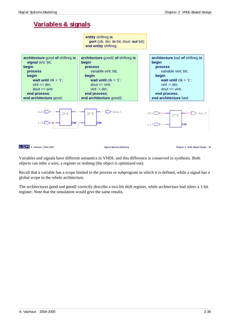
Variables & signalsVariables & signals
entity shiftreg isport (clk, din: in bit; dout: out bit);
end entity shiftreg;
architecture good of shiftreg issignal sint: bit;
beginprocessbegin
wait until clk = '1';sint <= din;dout <= sint;
end process;end architecture good;
architecture bad of shiftreg isbegin
processvariable vint: bit;
beginwait until clk = '1';vint := din;dout <= vint;
end process;end architecture bad;
architecture good2 of shiftreg isbegin
processvariable vint: bit;
beginwait until clk = '1';dout <= vint;vint := din;
end process;end architecture good2;
Variables and signals have different semantics in VHDL and this difference is conserved in synthesis. Both objects can infer a wire, a register or nothing (the object is optimized out).
Recall that a variable has a scope limited to the process or subprogram in which it is defined, while a signal has a global scope in the whole architecture.
The architectures good and good2 correctly describe a two-bit shift register, while architecture bad infers a 1-bit register. Note that the simulation would give the same results.

Digital Systems Modeling Chapter 2: VHDL-Based Design
A. Vachoux 2004-2005 2-37
A. Vachoux, 2004A. Vachoux, 2004--20052005 Digital Systems ModelingDigital Systems Modeling Chapter 2: VHDLChapter 2: VHDL--Based Design Based Design -- 3737
Initial valuesInitial values
entity E isport ( ...; clk, rst: in bit; ... );
end entity E;
architecture sync of E issignal S: bit_vector(15 downto 0);
beginprocessbegin
wait until clk = '1';if rst = '1' then
S <= (others => '0');-- + other initializations
else-- normal behavior...
end if;end process;
end architecture sync;
synchronous reset
entity E isport ( ...; clk, rst: in bit; ... );
end entity E;
architecture async of E issignal S: bit_vector(15 downto 0);
beginprocess (clk, rst)begin
if rst = '1' thenS <= (others => '0');-- + other initializations
elsif clk = ’1’ and clk’event then-- normal behavior...
end if;end process;
end architecture async;
asynchronous reset
Every VHDL object has an initial value that is either inherited by default from its type or explicitly defined in its declaration. As none of these ways are supported for synthesis, it is required to include explicit initialization code in the model. This is usually done as set/reset behavior and requires the declaration of additional set or reset signals.
A synchronous reset checks a reset signal at a clock edge. An asynchronous reset can be done independently of the clock signal.
The same approaches can be used for a set signal.
Synchronous designs usually require a way to put the circuit in a known state at power-up or when it is working.

Digital Systems Modeling Chapter 2: VHDL-Based Design
A. Vachoux 2004-2005 2-38
A. Vachoux, 2004A. Vachoux, 2004--20052005 Digital Systems ModelingDigital Systems Modeling Chapter 2: VHDLChapter 2: VHDL--Based Design Based Design -- 3838
OperatorsOperators
♦ logical: or and nor nand xor xnor
♦ Relational (a): = /= < (b) > (b) >= (b) <= (b)
♦ Shift & rotate (c): sll srl sla sra rol ror
♦ Addition: + (b) – (b) & (d)
♦ Unary: + –
♦ Multiplication: * (b),(e),(f) / (g),(h) mod (g) rem (g)
♦ Others: ** (i) abs not
priority
–
+
VHDL operators are supported for synthesis with some limitations:
(a) Result is of type boolean.
(b) Can be shared with another operator of the same kind and same priority level.
(c) Introduced in VHDL-1993. The IEEE 1076.6 standard mentions that they are not supported for synthesis and that the functions SHIFT_LEFT, SHIFT_RIGHT, ROTATE_LEFT and ROTATE_RIGHT from packages NUMERIC_BIT/_STD should be used instead. Synopsys tools however do support them.
(d) Concatenation operator '&' can be used to emulate shift and rotate operators.
(e) In general infers a combinational circuit. The inference mechanism depends on the tool (e.g. Synopsys' DesignWare).
(f) If the right operand is a multiple of 2, infers a simple left shifted register.
(g) Right operand must be a power of 2.
(h) If the right operand is a multiple of 2, infers a simple right shifted register.
(i) Powered operand must be a constant equal to 2.
Digital Systems Modeling Chapter 2: VHDL-Based Design
A. Vachoux 2004-2005 2-39
A. Vachoux, 2004A. Vachoux, 2004--20052005 Digital Systems ModelingDigital Systems Modeling Chapter 2: VHDLChapter 2: VHDL--Based Design Based Design -- 3939
Arithmetic operatorsArithmetic operators
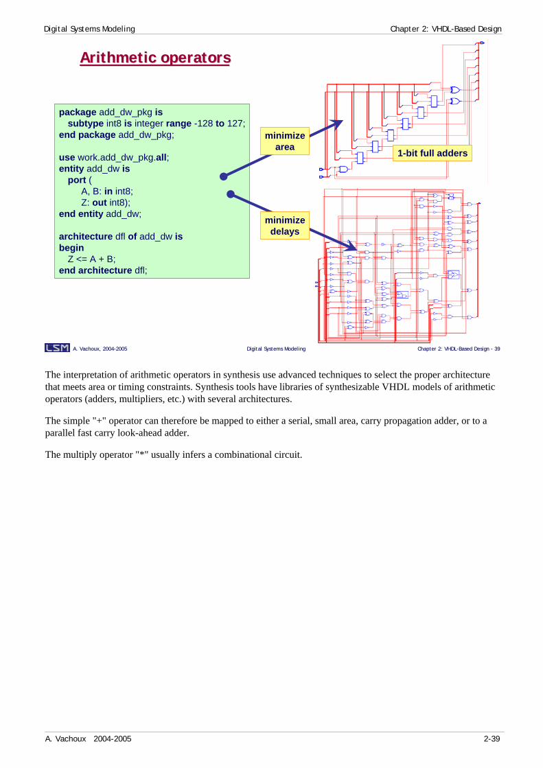
package add_dw_pkg issubtype int8 is integer range -128 to 127;
end package add_dw_pkg;
use work.add_dw_pkg.all;entity add_dw is
port (A, B: in int8;Z: out int8);
end entity add_dw;
architecture dfl of add_dw isbegin
Z <= A + B;end architecture dfl;
minimizedelays
minimizearea 1-bit full adders
The interpretation of arithmetic operators in synthesis use advanced techniques to select the proper architecture that meets area or timing constraints. Synthesis tools have libraries of synthesizable VHDL models of arithmetic operators (adders, multipliers, etc.) with several architectures.
The simple "+" operator can therefore be mapped to either a serial, small area, carry propagation adder, or to a parallel fast carry look-ahead adder.
The multiply operator "*" usually infers a combinational circuit.
Digital Systems Modeling Chapter 2: VHDL-Based Design
A. Vachoux 2004-2005 2-40
A. Vachoux, 2004A. Vachoux, 2004--20052005 Digital Systems ModelingDigital Systems Modeling Chapter 2: VHDLChapter 2: VHDL--Based Design Based Design -- 4040
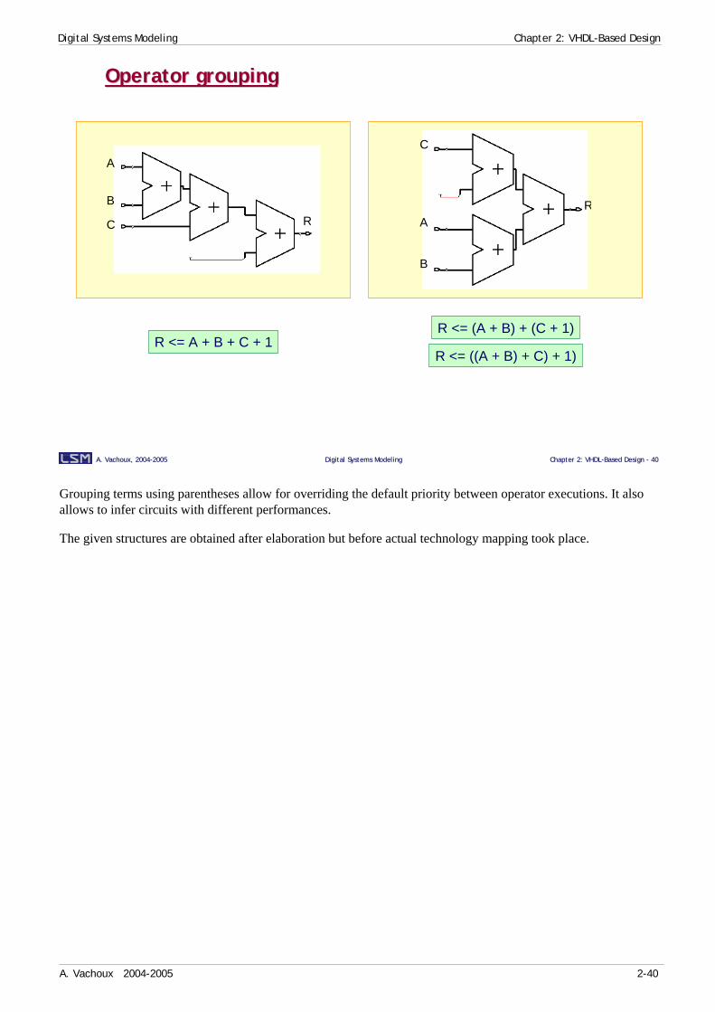
Operator groupingOperator grouping
R <= A + B + C + 1R <= (A + B) + (C + 1)
R <= ((A + B) + C) + 1)
A
B
C R A
B
C
R
Grouping terms using parentheses allow for overriding the default priority between operator executions. It also allows to infer circuits with different performances.
The given structures are obtained after elaboration but before actual technology mapping took place.
Digital Systems Modeling Chapter 2: VHDL-Based Design
A. Vachoux 2004-2005 2-41
A. Vachoux, 2004A. Vachoux, 2004--20052005 Digital Systems ModelingDigital Systems Modeling Chapter 2: VHDLChapter 2: VHDL--Based Design Based Design -- 4141
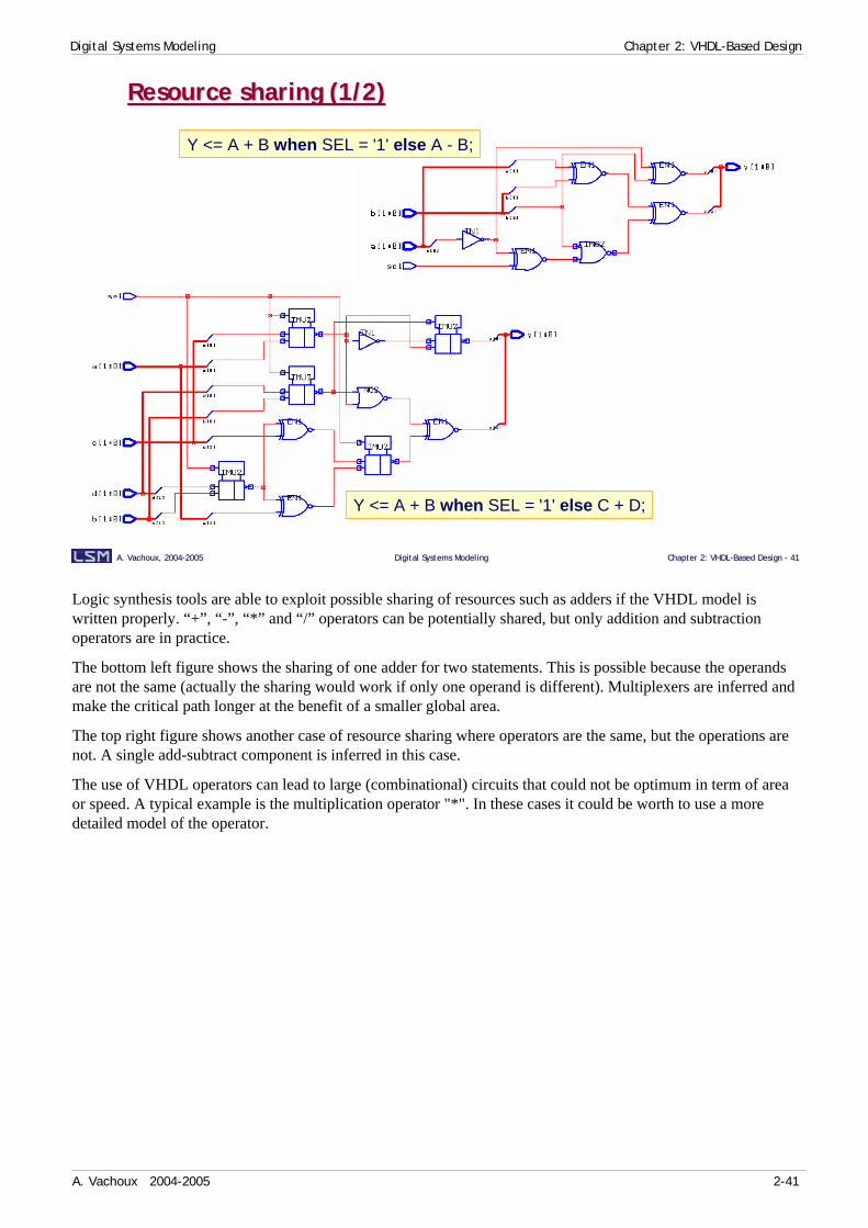
Resource sharing (1/2)Resource sharing (1/2)
Y <= A + B when SEL = '1' else A - B;
Y <= A + B when SEL = '1' else C + D;
Logic synthesis tools are able to exploit possible sharing of resources such as adders if the VHDL model is written properly. “+”, “-”, “*” and “/” operators can be potentially shared, but only addition and subtraction operators are in practice.
The bottom left figure shows the sharing of one adder for two statements. This is possible because the operands are not the same (actually the sharing would work if only one operand is different). Multiplexers are inferred and make the critical path longer at the benefit of a smaller global area.
The top right figure shows another case of resource sharing where operators are the same, but the operations are not. A single add-subtract component is inferred in this case.
The use of VHDL operators can lead to large (combinational) circuits that could not be optimum in term of area or speed. A typical example is the multiplication operator "*". In these cases it could be worth to use a more detailed model of the operator.
Digital Systems Modeling Chapter 2: VHDL-Based Design
A. Vachoux 2004-2005 2-42
A. Vachoux, 2004A. Vachoux, 2004--20052005 Digital Systems ModelingDigital Systems Modeling Chapter 2: VHDLChapter 2: VHDL--Based Design Based Design -- 4242
Resource sharing (2/2)Resource sharing (2/2)-- concurrent statementsSUM1 <= A + B;SUM2 <= C + D;Y <= SUM1 when SEL = ’1’ else SUM2;
-- sequential statementsSUM1 := A + B;SUM2 := C + D;if SEL = ’1’ then
Y <= SUM1;else
Y <= SUM2;end if;
D
SEL
B
ADD
CA
MUX
Y
ADD
-- concurrent statementsMUX1 <= A when SEL = ’1’ else C;MUX2 <= B when SEL = ’1’ else D;Y <= MUX1 + MUX2;
-- sequential statementsif SEL = ’1’ then
MUX1 := A;MUX2 := B;
elseMUX1 := C;MUX2 := D;
end if;Y <= MUX1 + MUX2;
D
SEL
B
MUXSEL
CA
ADD
Y
MUX
if SEL = ’1’ thenY <= A + B;
end if;
if SEL /= ’1’ thenY <= E + F;
end if;
No possibleresourcesharing
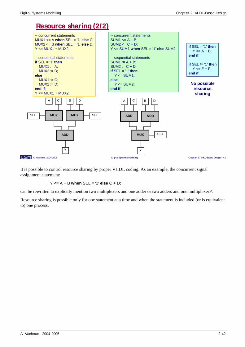
It is possible to control resource sharing by proper VHDL coding. As an example, the concurrent signal assignment statement:
Y <= A + B when SEL = '1' else C + D;
can be rewritten to explicitly mention two multiplexers and one adder or two adders and one multiplexerP.
Resource sharing is possible only for one statement at a time and when the statement is included (or is equivalent to) one process.

Digital Systems Modeling Chapter 2: VHDL-Based Design
A. Vachoux 2004-2005 2-43
A. Vachoux, 2004A. Vachoux, 2004--20052005 Digital Systems ModelingDigital Systems Modeling Chapter 2: VHDLChapter 2: VHDL--Based Design Based Design -- 4343
ProcessProcess
♦ A process infers a combinational circuit if and only if all the following conditions are met:
1) The process has a sensitivity list
2) The process does not declare variables orvariables are always assigned before read
3) All signals that are read in the process are in the sensitivity list
4) All variables or signals are assigned in every branch of the execution flow (if or case statement)
♦ Otherwise a sequential circuit is inferred• Flip-flops are usually required• Latches are often not required
The way process statements are written can infer a combinational or a sequential circuit. Combinational circuits have asynchronous behaviors which are only driven by events on signals. Sequential circuits have behaviors which are synchronous to a clock signal and uses flip-flop or latch registers.
The use of concurrent signal assignments always infers combinational circuits.

Digital Systems Modeling Chapter 2: VHDL-Based Design
A. Vachoux 2004-2005 2-44
A. Vachoux, 2004A. Vachoux, 2004--20052005 Digital Systems ModelingDigital Systems Modeling Chapter 2: VHDLChapter 2: VHDL--Based Design Based Design -- 4444
Clock signal inferenceClock signal inference
♦ Recognized code templates:• In if and wait until statements
• In wait until statement
♦ Signal name does not convey any meaning for synthesis• Recommended to use meaningful names anyway (e.g. clk)
rising_edge ( clock-signal-name )
clock-signal-name = '1'
falling_edge (clock-signal-name )
clock-signal-name 'event and clock-signal-name = '1'
clock-signal-name 'event and clock-signal-name = '0'
not clock-signal-name'stable and clock-signal-name = '0'
not clock-signal-name'stable and clock-signal-name = '1'
clock-signal-name = '0'

Digital Systems Modeling Chapter 2: VHDL-Based Design
A. Vachoux 2004-2005 2-45
A. Vachoux, 2004A. Vachoux, 2004--20052005 Digital Systems ModelingDigital Systems Modeling Chapter 2: VHDLChapter 2: VHDL--Based Design Based Design -- 4545
Wait and if statementsWait and if statements
♦ Wait statement for inferring behavior sensitive to signal edges
♦ Several wait statements in a process is legal if and only if they relate to the same (clock) signal and the same rising or falling signal edge
♦ If statements for inferring behavior sensitive to signal edges or to signal levels
processdeclarations
beginwait until clock-edge; -- must be the first statement in the processsequential statements
end process;
process (clock-signal-name, …)declarations
begindo not include any statement hereif clock-edge then
sequential statementsend if;do not include any statement here
end process;
process (clock-signal-name, …)declarations
begindo not include any statement hereif signal-level then
sequential statementsend if;do not include any statement here
end process;
wait statements allow for inferring edge-sensitive sequential elements (flip-flops).
Synchronizing a process on different signals or different edges on the same signal is not supported in synthesis. If this is really needed, several processes must be used.
The use of several wait statements in a process sensitive on the same (clock) signal and on the same signal edge is a way to model finite state machines with implicit states, or sequencers.
if statements also allow for inferring level-sensitive sequential elements (latches).

Digital Systems Modeling Chapter 2: VHDL-Based Design
A. Vachoux 2004-2005 2-46
A. Vachoux, 2004A. Vachoux, 2004--20052005 Digital Systems ModelingDigital Systems Modeling Chapter 2: VHDLChapter 2: VHDL--Based Design Based Design -- 4646
Signal assignmentSignal assignment
♦ Delay clause is ignored
♦ Delay modes are not allowed• reject, inertial
♦ Multiple element waveform is not allowed
S <= ’0’ after 10 ns;
S <= ’1’, ’0’ after 20 ns, ’1’ after 30 ns; -- error
S <= '0';
The right-hand part of the signal assignment can be a literal value (e.g. '0' or '1') or any legal expression that evaluates to a value of the same type as those of the assigned signal.
Digital Systems Modeling Chapter 2: VHDL-Based Design
A. Vachoux 2004-2005 2-47
A. Vachoux, 2004A. Vachoux, 2004--20052005 Digital Systems ModelingDigital Systems Modeling Chapter 2: VHDLChapter 2: VHDL--Based Design Based Design -- 4747
architecture priority1 of ifstmt isbegin
process (A, B, C, D, sel)begin
Z <= ’0’;if sel(0) = ’1’ then
Z <= A;end if;if sel(1) = ’1’ then
Z <= B;end if;if sel(2) = ’1’ then
Z <= C;end if;if sel(3) = ’1’ then
Z <= D;end if;
end process;end architecture priority1;
Sequential if statementSequential if statement
♦ Implies a pritority
sel(0
) sel(1
)
sel(2
) sel(3
)
architecture priority2 of ifstmt isbegin
process (A, B, C, D, sel)begin
Z <= ’0’;if sel(0) = ’1’ then
Z <= A;elsif sel(1) = ’1’ then
Z <= B;elsif sel(2) = ’1’ then
Z <= C;elsif sel(3) = ’1’ then
Z <= D;end if;
end process;end architecture priority2;
sel(0
)
sel(1
)
sel(2
)
sel(3
)
entity ifstmt isport (
A, B, C, D: in bit;sel: in bit_vector(3 downto 0);Z: out bit);
end entity ifstmt;
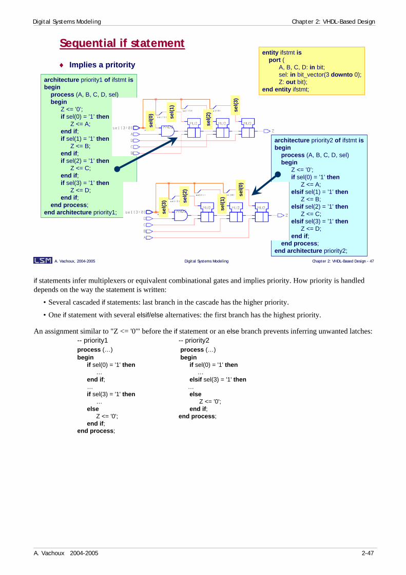
if statements infer multiplexers or equivalent combinational gates and implies priority. How priority is handled depends on the way the statement is written:
• Several cascaded if statements: last branch in the cascade has the higher priority.
• One if statement with several elsif/else alternatives: the first branch has the highest priority.
An assignment similar to "Z <= '0'" before the if statement or an else branch prevents inferring unwanted latches:-- priority1 -- priority2process (…) process (…) begin begin
if sel(0) = '1' then if sel(0) = '1' then … …
end if; elsif sel(3) = '1' then … …if sel(3) = '1' then else
… Z <= '0';else end if;
Z <= '0'; end process;end if;
end process;
Digital Systems Modeling Chapter 2: VHDL-Based Design
A. Vachoux 2004-2005 2-48
A. Vachoux, 2004A. Vachoux, 2004--20052005 Digital Systems ModelingDigital Systems Modeling Chapter 2: VHDLChapter 2: VHDL--Based Design Based Design -- 4848
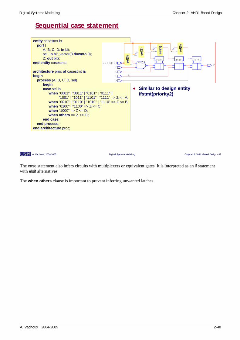
entity casestmt isport (
A, B, C, D: in bit;sel: in bit_vector(3 downto 0);Z: out bit);
end entity casestmt;
architecture proc of casestmt isbegin
process (A, B, C, D, sel)begincase sel is
when "0001" | "0011" | "0101" | "0111" |"1001" | "1011" | "1101" | "1111" => Z <= A;
when "0010" | "0110" | "1010" | "1110" => Z <= B;when "0100" | "1100" => Z <= C;when "1000" => Z <= D;when others => Z <= ’0’;
end case;end process;
end architecture proc;
Sequential case statementSequential case statement
♦ Similar to design entity ifstmt(priority2)
sel(0
)
sel(1
)
sel(2
)
sel(3
)
The case statement also infers circuits with multiplexers or equivalent gates. It is interpreted as an if statement with elsif alternatives
The when others clause is important to prevent inferring unwanted latches.
Digital Systems Modeling Chapter 2: VHDL-Based Design
A. Vachoux 2004-2005 2-49
A. Vachoux, 2004A. Vachoux, 2004--20052005 Digital Systems ModelingDigital Systems Modeling Chapter 2: VHDLChapter 2: VHDL--Based Design Based Design -- 4949
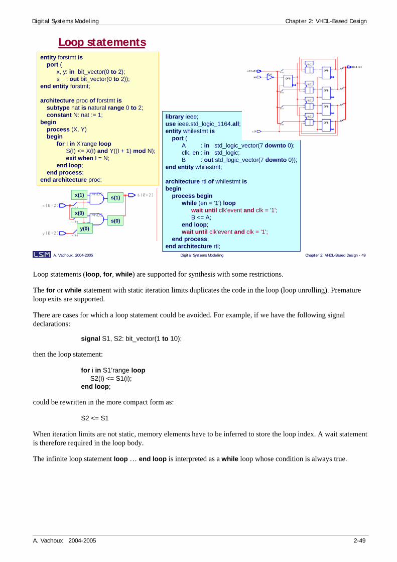
Loop statementsLoop statementsentity forstmt is
port (x, y: in bit_vector(0 to 2);s : out bit_vector(0 to 2));
end entity forstmt;
architecture proc of forstmt issubtype nat is natural range 0 to 2;constant N: nat := 1;
beginprocess (X, Y)begin
for I in X'range loopS(I) <= X(I) and Y((I + 1) mod N);exit when I = N;
end loop;end process;
end architecture proc;
x(1)
x(0)
y(0)
s(1)
s(0)
library ieee;use ieee.std_logic_1164.all;entity whilestmt is
port (A : in std_logic_vector(7 downto 0);clk, en : in std_logic;B : out std_logic_vector(7 downto 0));
end entity whilestmt;
architecture rtl of whilestmt isbegin
process beginwhile (en = '1') loop
wait until clk'event and clk = '1';B <= A;
end loop;wait until clk'event and clk = '1';
end process;end architecture rtl;
Loop statements (loop, for, while) are supported for synthesis with some restrictions.
The for or while statement with static iteration limits duplicates the code in the loop (loop unrolling). Premature loop exits are supported.
There are cases for which a loop statement could be avoided. For example, if we have the following signal declarations:
signal S1, S2: bit_vector(1 to 10);
then the loop statement:
for i in S1’range loopS2(i) <= S1(i);
end loop;
could be rewritten in the more compact form as:
S2 <= S1
When iteration limits are not static, memory elements have to be inferred to store the loop index. A wait statement is therefore required in the loop body.
The infinite loop statement loop … end loop is interpreted as a while loop whose condition is always true.

Digital Systems Modeling Chapter 2: VHDL-Based Design
A. Vachoux 2004-2005 2-50
A. Vachoux, 2004A. Vachoux, 2004--20052005 Digital Systems ModelingDigital Systems Modeling Chapter 2: VHDLChapter 2: VHDL--Based Design Based Design -- 5050
SubprogramsSubprograms
♦ Do not infer any structural hierarchy (≠ components)
♦ A function call always infers a combinational circuit• Resolution functions and conversion functions are ignored
♦ A procedure call infers a combinational circuit if and only if:
1) Its arguments are of mode in or out
2) It does not include any wait statement
3) It does not have side effects
Otherwise it infers a sequential circuit
A function call always infers a combinational circuit since it can only appears in an expression.
A procedure call can infer either a combinational or a sequential circuit. Thisis valid for both concurrent and sequential forms of the procedure call.

Digital Systems Modeling Chapter 2: VHDL-Based Design
A. Vachoux 2004-2005 2-51
A. Vachoux, 2004A. Vachoux, 2004--20052005 Digital Systems ModelingDigital Systems Modeling Chapter 2: VHDLChapter 2: VHDL--Based Design Based Design -- 5151
ProcedureProcedure
architecture a of procstmt isbegin
process (inar)
procedure swap (d: inout darray; l, h: in postitive) isvariable tmp: data;
beginif d(l) > d(h) then
tmp := d(l);d(l) := d(h);d(h) := tmp;
end if;end swap;
variable tmpar: darray;begin
tmpar := inar;swap(tmpar,1,2);swap(tmpar,2,3);swap(tmpar,1,2);outar <= tmpar;
end process;end architecture a;
package proc_pkg issubtype data is integer range 0 to 3;type darray is array (1 to 3) of data;
end package proc_pkg;
use work.proc_pkg.all;entity procstmt is
port (inar : in darray;outar: out darray);
end entity procstmt;
Digital Systems Modeling Chapter 2: VHDL-Based Design
A. Vachoux 2004-2005 2-52
A. Vachoux, 2004A. Vachoux, 2004--20052005 Digital Systems ModelingDigital Systems Modeling Chapter 2: VHDLChapter 2: VHDL--Based Design Based Design -- 5252
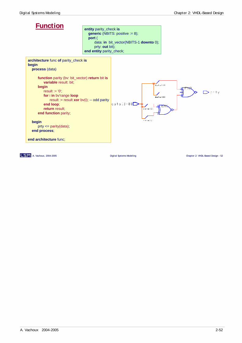
FunctionFunction entity parity_check isgeneric (NBITS: positive := 8);port (
data: in bit_vector(NBITS-1 downto 0);prty: out bit);
end entity parity_check;
architecture func of parity_check isbegin
process (data)
function parity (bv: bit_vector) return bit isvariable result: bit;
beginresult := '0';for i in bv'range loop
result := result xor bv(i); -- odd parityend loop;return result;
end function parity;
beginprty <= parity(data);
end process;
end architecture func;

Digital Systems Modeling Chapter 2: VHDL-Based Design
A. Vachoux 2004-2005 2-53
A. Vachoux, 2004A. Vachoux, 2004--20052005 Digital Systems ModelingDigital Systems Modeling Chapter 2: VHDLChapter 2: VHDL--Based Design Based Design -- 5353
Concurrent statementsConcurrent statements
♦ Signal assignment always infers combinational circuits
♦ Concurrent procedure callalways infers combinational circuits
• Wait statement not allowed in procedure body• Do not infer any structural hierarchy
♦ Component instance• Defines a structural hierarchy which is conserved through synthesis• Possible operations on components during synthesis:
Make instances unique (uniquify)Make instances frozen (don't touch)Flatten hierarchy (ungroup)
♦ generate statement• Both iterative and conditional forms are supported• Local declarations not supported
-- conditional form (else is mandatory)S2 <= (S1 and B) when CMD = ’0’ else (C or D);
-- selective formwith CMD select
S2 <= (S1 and B) when ’0’ else(C or D) when others;
The structural hierarchy implied by component instances is conserved through synthesis. It is recommended to use components at the RTL level to ease the management of complex designs. This also eases the definition of timing constraints to critical internal parts of the design.
All instances of the same component usually refer to the same component description. It is required to make each instance unique uniquify) to allow individual optimization of each instance.
A component may be synthesized separately and then made frozen (don’t touch) when synthezising one level up in the hierarchy.
The hierarchy can be flattened (ungrouped) during synthesis to allow further optimization across component boundaries.

Digital Systems Modeling Chapter 2: VHDL-Based Design
A. Vachoux 2004-2005 2-54
A. Vachoux, 2004A. Vachoux, 2004--20052005 Digital Systems ModelingDigital Systems Modeling Chapter 2: VHDLChapter 2: VHDL--Based Design Based Design -- 5454
MiscellaneousMiscellaneous
♦ Generic parameters• Of type integer or derived• Of an enumerated type
♦ Configurations• Default configuration only• (Direct instantiation)
Default configuration means that there is a component declaration that has exactly the same signature as the entity declaration of a design entity in the working library. Signature includes the signal names, modes and types.

Digital Systems Modeling Chapter 2: VHDL-Based Design
A. Vachoux 2004-2005 2-55
A. Vachoux, 2004A. Vachoux, 2004--20052005 Digital Systems ModelingDigital Systems Modeling Chapter 2: VHDLChapter 2: VHDL--Based Design Based Design -- 5555
Test bench modelTest bench modelTest bench model
UUT(Unit Under Test)
Functional modelRTL model
Gate-level model
• Stimulusgenerator
• Interfaceemulator
• Errorgenerator
• Data collector
• Interfaceemulator
• Outputchecks
entity tb_xxx isend entity tb_xxx;
architecture bench of tb_xxx is…
beginUUT: entity work.E(A) port map (…);stimulus: process begin
…end process stimulus;verification: process begin
…end process verification;
end architecture bench;
A test bench model aims at validating a functional, RTL or gate-level model. The kind of valifdation depends on the abstraction level of the unit under test:
• Functional model: interface behavior, communication protocol.
• RTL model: design architecture, control and data parts.
• Gate-level model: timings.
A test bench model can be written in VHDL. Three components may be identified:
• A stimulus generator whose task is to define the stimulus to apply to the unit under test. Stimulus can be defined in VHDL or in a format closer to the targetted application (e.g. in assembly language or C). In the latter case, the generator has to translate abstract stimulus in VHDL and possibly apply interface constraints (e.g. protocol, delays). The generator may also explicitly introduce errors.
• The unit under test (UUT).
• A collector component whose task is to collect output data from the UUT, to possibly translate them into a more readable form and to make checks. Checks can be made either by comparing the output values to ideal values defined in the component, or by comparing output values to other output values generated by a second ideal model stimulated in the same way (e.g. comparing the outputs of a RTL model and a gate-level model).
The unit under test is instantiated as a component. The stimulus and the collector components may be instantiated as components or defined as processes.
More details on test bench modeling and verification methods can be found in [Bergeron00].
Digital Systems Modeling Chapter 2: VHDL-Based Design
A. Vachoux 2004-2005 2-56
A. Vachoux, 2004A. Vachoux, 2004--20052005 Digital Systems ModelingDigital Systems Modeling Chapter 2: VHDLChapter 2: VHDL--Based Design Based Design -- 5656
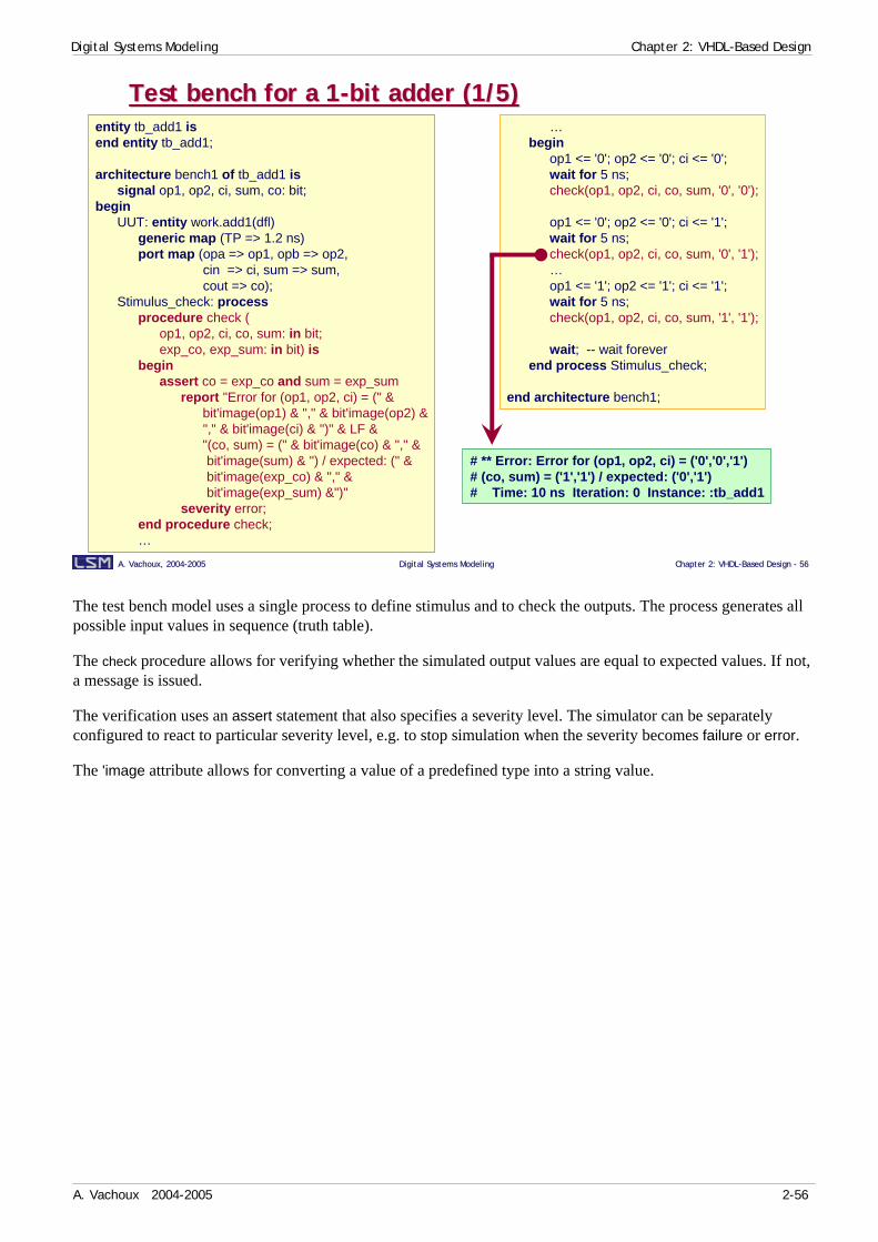
Test bench for a 1Test bench for a 1--bit adder (1/5)bit adder (1/5)entity tb_add1 isend entity tb_add1;
architecture bench1 of tb_add1 issignal op1, op2, ci, sum, co: bit;
beginUUT: entity work.add1(dfl)
generic map (TP => 1.2 ns)port map (opa => op1, opb => op2,
cin => ci, sum => sum,cout => co);
Stimulus_check: processprocedure check (
op1, op2, ci, co, sum: in bit;exp_co, exp_sum: in bit) is
beginassert co = exp_co and sum = exp_sum
report "Error for (op1, op2, ci) = (" &bit'image(op1) & "," & bit'image(op2) &"," & bit'image(ci) & ")" & LF &"(co, sum) = (" & bit'image(co) & "," &bit'image(sum) & ") / expected: (" &bit'image(exp_co) & "," &bit'image(exp_sum) &")"
severity error;end procedure check;…
…begin
op1 <= '0'; op2 <= '0'; ci <= '0';wait for 5 ns;check(op1, op2, ci, co, sum, '0', '0');
op1 <= '0'; op2 <= '0'; ci <= '1';wait for 5 ns;check(op1, op2, ci, co, sum, '0', '1');…op1 <= '1'; op2 <= '1'; ci <= '1';wait for 5 ns;check(op1, op2, ci, co, sum, '1', '1');
wait; -- wait foreverend process Stimulus_check;
end architecture bench1;
# ** Error: Error for (op1, op2, ci) = ('0','0','1')# (co, sum) = ('1','1') / expected: ('0','1')# Time: 10 ns Iteration: 0 Instance: :tb_add1
The test bench model uses a single process to define stimulus and to check the outputs. The process generates all possible input values in sequence (truth table).
The check procedure allows for verifying whether the simulated output values are equal to expected values. If not, a message is issued.
The verification uses an assert statement that also specifies a severity level. The simulator can be separately configured to react to particular severity level, e.g. to stop simulation when the severity becomes failure or error.
The 'image attribute allows for converting a value of a predefined type into a string value.
Digital Systems Modeling Chapter 2: VHDL-Based Design
A. Vachoux 2004-2005 2-57
A. Vachoux, 2004A. Vachoux, 2004--20052005 Digital Systems ModelingDigital Systems Modeling Chapter 2: VHDLChapter 2: VHDL--Based Design Based Design -- 5757
Test bench for a 1Test bench for a 1--bit adder (2/5)bit adder (2/5)architecture bench2 of tb_add1 is
signal op1, op2, ci: bit;signal sum_dfl, sum_str, co_dfl, co_str: bit;
begin
UUT: entity work.add1(str)generic map (TP => 1.2 ns)port map (
opa => op1, opb => op2, cin => ci,sum => sum_str; cout => co_str);
UREF: entity work.add1(dfl)generic map (TP => 1.2 ns)port map (
opa => op1, opb => op2, cin => ci,sum => sum_dfl; cout => co_dfl);
…
…Stimulus_check: process
procedure check (op1, op2, ci, co, sum: in bit;exp_co, exp_sum: in bit) is
begin…
end procedure check;
beginop1 <= '0'; op2 <= '0'; ci <= '0';wait for 5 ns;check(op1, op2, ci, co_str, sum_str, co_dfl, sum_dfl);
op1 <= '0'; op2 <= '0'; ci <= '1';wait for 5 ns;check(op1, op2, ci, co_str, sum_str, co_dfl, sum_dfl);…op1 <= '1'; op2 <= '1'; ci <= '1';wait for 5 ns;check(op1, op2, ci, co_str, sum_str, co_dfl, sum_dfl);
wait; -- wait foreverend process Stimulus_check;
end architecture bench2;
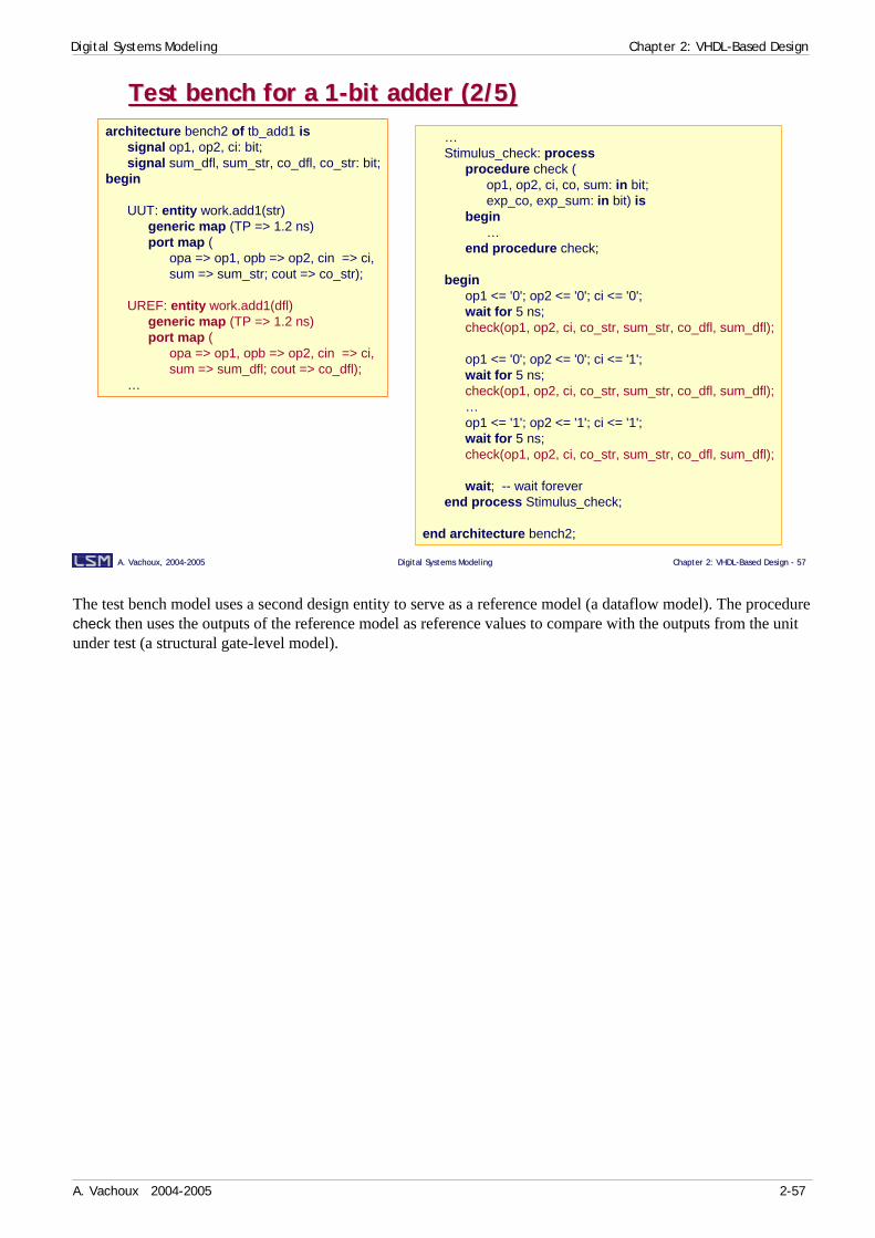
The test bench model uses a second design entity to serve as a reference model (a dataflow model). The procedure check then uses the outputs of the reference model as reference values to compare with the outputs from the unit under test (a structural gate-level model).
Digital Systems Modeling Chapter 2: VHDL-Based Design
A. Vachoux 2004-2005 2-58
A. Vachoux, 2004A. Vachoux, 2004--20052005 Digital Systems ModelingDigital Systems Modeling Chapter 2: VHDLChapter 2: VHDL--Based Design Based Design -- 5858
Test bench for a 1Test bench for a 1--bit adder (3/5)bit adder (3/5)architecture bench3 of tb_add1 is
signal op1, op2, ci, sum, co: bit;begin
UUT: entity work.add1(dfl)generic map (TP => 1.2 ns)port map (opa => op1, opb => op2,
cin => ci, sum => sum,cout => co);
Stimulus_check: processtype table_elem is record
x, y, ci, co, s: bit;end record;type table is array (0 to 7) of table_elem;constant TT: table :=
(-- x -- y -- ci ------ co -- s --('0', '0', '0', '0', '0'),('0', '0', '1', '0', '1'),('0', '1', '0', '0', '1'),('0', '1', '1', '1', '0'),('1', '0', '0', '0', '1'),('1', '0', '1', '1', '0'),('1', '1', '0', '1', '0'),('1', '1', '1', '1', '1'));
…
…begin
for i in TT'range loopop1 <= TT(i).x; op2 <= TT(i).y; ci <= TT(i).ci;wait for 5 ns;
assert co = TT(i).co and sum = TT(i).sreport "Error for (op1, op2, ci) = (" &
bit'image(op1) & "," & bit'image(op2) & "," &bit'image(ci) & ")" & LF &"(co, sum) = (" & bit'image(co) & "," &bit'image(sum) & ") / expected: (" &bit'image(TT(i).co) & "," &bit'image(TT(i).s) &")"
severity error;
end loop;wait; -- wait forever
end process Stimulus_check;
end architecture bench3;
# ** Error: Error for (op1, op2, ci) = ('0','1','1')# (co, sum) = ('1','1') / expected: ('1','0')# Time: 20 ns Iteration: 0 Instance: :tb_add1
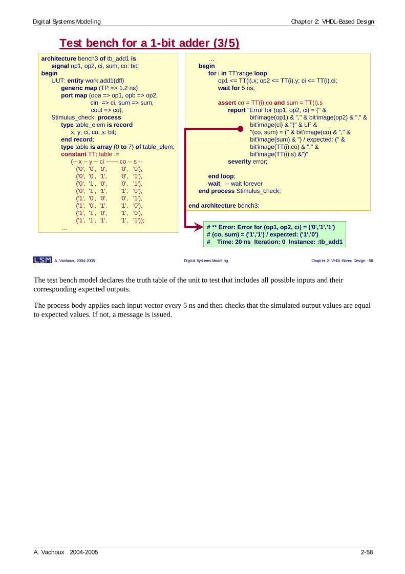
The test bench model declares the truth table of the unit to test that includes all possible inputs and their corresponding expected outputs.
The process body applies each input vector every 5 ns and then checks that the simulated output values are equal to expected values. If not, a message is issued.

Digital Systems Modeling Chapter 2: VHDL-Based Design
A. Vachoux 2004-2005 2-59
A. Vachoux, 2004A. Vachoux, 2004--20052005 Digital Systems ModelingDigital Systems Modeling Chapter 2: VHDLChapter 2: VHDL--Based Design Based Design -- 5959
Test bench for a 1Test bench for a 1--bit adder (4/5)bit adder (4/5)
…variable tt: bit_vector(1 to 5);variable exp_co; exp_sum: bit;variable ll: line;
beginreadline(add1_tt, ll); -- en-têtewhile not endfile(add1_tt) loop
readline(add1_tt, ll);read(ll, tt);op1 <= tt(1); op2 <= tt(2); ci <= tt(3);exp_co := tt(4); exp_sum := tt(5);wait for 5 ns;check(op1, op2, ci, co, sum, exp_co, exp_sum);
end loop;wait; -- wait forever
end process Stimulus_check;
end architecture bench4;
use STD.textio.all;architecture bench4 of tb_add1 is
file add1_tt: text open read_mode is "add1_tt.dat";signal op1, op2, ci, sum, co: bit;
beginUUT: entity work.add1(dfl)
generic map (TP => 1.2 ns)port map (opa => op1, opb => op2,
cin => ci, sum => sum,cout => co);
Stimulus_check: processprocedure check (
op1, op2, ci, co, sum: in bit;exp_co, exp_sum: in bit) is
beginassert co = exp_co and sum = exp_sum
report "Error for (op1, op2, ci) = (" &bit'image(op1) & "," & bit'image(op2) &"," & bit'image(ci) & ")" & LF &"(co, sum) = (" & bit'image(co) & "," &bit'image(sum) & ") / expected: (" &bit'image(exp_co) & "," &bit'image(exp_sum) &")"
severity error;end procedure check;…
# op1 op2 ci co sum0000000101010010111010001101101101011111
The truth table is now read from a file.

Digital Systems Modeling Chapter 2: VHDL-Based Design
A. Vachoux 2004-2005 2-60
A. Vachoux, 2004A. Vachoux, 2004--20052005 Digital Systems ModelingDigital Systems Modeling Chapter 2: VHDLChapter 2: VHDL--Based Design Based Design -- 6060
Test bench for a 1Test bench for a 1--bit adder (5/5)bit adder (5/5)use STD.textio.all;architecture bench5 of tb_add1 is
file add1_tt: text open read_mode is "add1_tt.dat";file flog: text open write_mode is "tb_add1.log";signal op1, op2, ci, sum, co: bit;
beginUUT: entity work.add1(dfl)
generic map (TP => 1.2 ns)port map (opa => op1, opb => op2,
cin => ci, sum => sum,cout => co);
Stimulus_check: processprocedure check (op1, op2, ci, co, sum: in bit;
exp_co, exp_sum: in bit) isbegin
…end procedure check;variable tt: bit_vector(1 to 5);variable exp_co; exp_sum: bit;variable llr, llw: line;
beginreadline(add1_tt, llr); -- en-têtewrite(llw,
string'("time -- op1 op2 ci exp_co exp_sum co sum"));writeline(flog, llw);…
…while not endfile(add1_tt) loop
readline(add1_tt, llr);read(llr, tt);write(llw, time'image(now) & string'(" -- ") &
bit'image(tt(1)) & " " & bit'image(tt(2)) & " "bit'image(tt(3)) & " " & bit'image(tt(4)) & " " &bit'image(tt(5)));
op1 <= tt(1); op2 <= tt(2); ci <= tt(3);exp_co := tt(4); exp_sum := tt(5);wait for 5 ns;write(llw, " " & bit'image(co) & " " & bit'image(sum));writeline(flog, llw);check(op1, op2, ci, co, sum, exp_co, exp_sum);
end loop;wait; -- wait forever
end process Stimulus_check;
end architecture bench5;time -- op1 op2 ci exp_co exp_sum co sum0 ns -- '0' '0' '0' '0' '0' '0' '0'5 ns -- '0' '0' '1' '0' '1' '0' '1'10 ns -- '0' '1' '0' '0' '1' '0' '1'15 ns -- '0' '1' '1' '1' '0' '1' '0'20 ns -- '1' '0' '0' '0' '1' '0' '1'25 ns -- '1' '0' '1' '1' '0' '1' '0'30 ns -- '1' '1' '0' '1' '0' '1' '0'35 ns -- '1' '1' '1' '1' '1' '1' '1'
The output of the verification process is now written in a log file.
Digital Systems Modeling Chapter 2: VHDL-Based Design
A. Vachoux 2004-2005 2-61
A. Vachoux, 2004A. Vachoux, 2004--20052005 Digital Systems ModelingDigital Systems Modeling Chapter 2: VHDLChapter 2: VHDL--Based Design Based Design -- 6161
Clock generationClock generation
library ieee;use ieee.std_logic_1164.all;
architecture bench of tb_xxx isconstant CLK_PER: time := 20 ns;signal clk: std_logic := '0';
beginUUT: …clk <= not clk after CLK_PER/2;Stimulus_check: process
…end process Stimulus_check
end architecture bench;
library ieee;use ieee.std_logic_1164.all;
architecture bench of tb_xxx issignal phi1, phi2: std_logic := '0';procedure clkgen (
signal clk: out bit;constant Tperiod, Tpulse, Tphase: in time) is
beginwait for Tphase;loop
clk <= '1', '0' after Tpulse;wait for Tperiod;
end loop;end procedure clkgen;…
beginUUT: …gen_phi1: clkgen(phi1, Tperiod => 50 ns,
Tpulse => 20 ns,Tphase => 0 ns);
gen_phi2: clkgen(phi2, Tperiod => 50 ns,Tpulse => 20 ns,Tphase => 25 ns);
…end architecture bench;
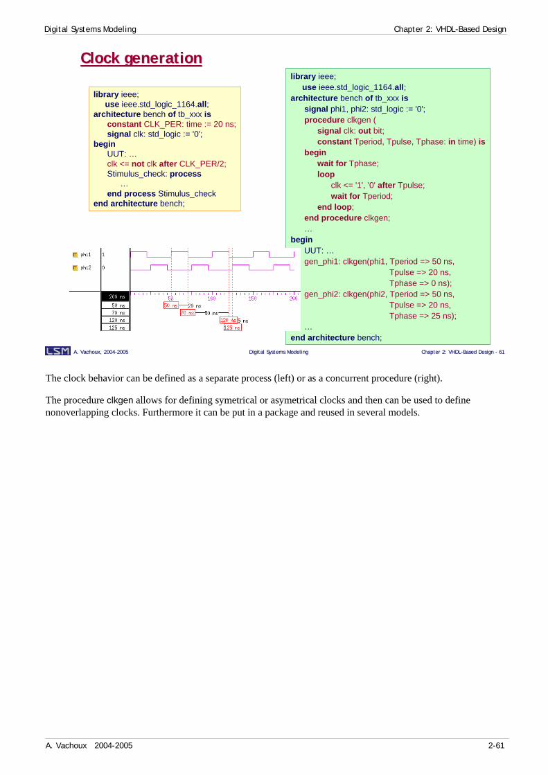
The clock behavior can be defined as a separate process (left) or as a concurrent procedure (right).
The procedure clkgen allows for defining symetrical or asymetrical clocks and then can be used to define nonoverlapping clocks. Furthermore it can be put in a package and reused in several models.
Digital Systems Modeling Chapter 2: VHDL-Based Design
A. Vachoux 2004-2005 2-62
A. Vachoux, 2004A. Vachoux, 2004--20052005 Digital Systems ModelingDigital Systems Modeling Chapter 2: VHDLChapter 2: VHDL--Based Design Based Design -- 6262
Waveform generation (1/2)Waveform generation (1/2)TL
THlibrary ieee;
use ieee.math_real.all;
architecture bench of tb_xxx is
constant PC_MIN: real : = 0.3; -- % min. value ('0')constant PC_MAX: real := 0.3; -- % max. value ('1')
constant TL_MIN : time := 5 ns;constant TL_MAX: time := 7 ns;
constant TH_MIN : time := 3 ns;constant TH_MAX: time := 5 ns;
signal S: bit := '0';begin
processvariable seed1: positive := 3812;variable seed2: positive := 915;…
…impure function random return real is
variable rnd: real;begin
uniform(seed1, seed2, rnd);if rnd < PC_MIN then
return 0.0;elsif rnd < PC_MIN + PC_MAX then
return 1.0;else
return rnd;end if;
end function random;begin
S <= '0';wait for TL_MIN + (TL_MAX - TL_MIN)*random;S <= '1';wait for TH_MIN + (TH_MAX - TH_MIN)*random;
end process;…
end architecture bench;
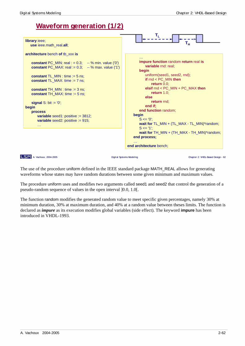
The use of the procedure uniform defined in the IEEE standard package MATH_REAL allows for generating waveforms whose states may have random durations between some given minimum and maximum values.
The procedure uniform uses and modifies two arguments called seed1 and seed2 that control the generation of a pseudo-random sequence of values in the open interval ]0.0, 1.0[.
The function random modifies the generated random value to meet specific given percentages, namely 30% at minimum duration, 30% at maximum duration, and 40% at a random value between theses limits. The function is declared as impure as its execution modifies global variables (side effect). The keyword impure has been introduced in VHDL-1993.
Digital Systems Modeling Chapter 2: VHDL-Based Design
A. Vachoux 2004-2005 2-63
A. Vachoux, 2004A. Vachoux, 2004--20052005 Digital Systems ModelingDigital Systems Modeling Chapter 2: VHDLChapter 2: VHDL--Based Design Based Design -- 6363
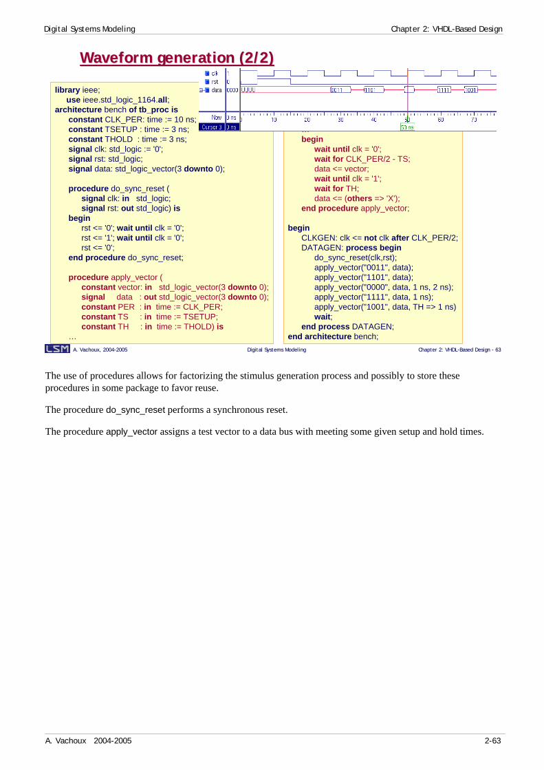
Waveform generation (2/2)Waveform generation (2/2)
library ieee;use ieee.std_logic_1164.all;
architecture bench of tb_proc isconstant CLK_PER: time := 10 ns;constant TSETUP : time := 3 ns;constant THOLD : time := 3 ns;signal clk: std_logic := '0';signal rst: std_logic;signal data: std_logic_vector(3 downto 0);
procedure do_sync_reset (signal clk: in std_logic;signal rst: out std_logic) is
beginrst <= '0'; wait until clk = '0';rst <= '1'; wait until clk = '0';rst <= '0';
end procedure do_sync_reset;
procedure apply_vector (constant vector: in std_logic_vector(3 downto 0);signal data : out std_logic_vector(3 downto 0);constant PER : in time := CLK_PER;constant TS : in time := TSETUP;constant TH : in time := THOLD) is
…
…begin
wait until clk = '0';wait for CLK_PER/2 - TS; data <= vector;wait until clk = '1';wait for TH;data <= (others => 'X');
end procedure apply_vector;
beginCLKGEN: clk <= not clk after CLK_PER/2;DATAGEN: process begin
do_sync_reset(clk,rst);apply_vector("0011", data);apply_vector("1101", data);apply_vector("0000", data, 1 ns, 2 ns);apply_vector("1111", data, 1 ns);apply_vector("1001", data, TH => 1 ns)wait;
end process DATAGEN;end architecture bench;
The use of procedures allows for factorizing the stimulus generation process and possibly to store these procedures in some package to favor reuse.
The procedure do_sync_reset performs a synchronous reset.
The procedure apply_vector assigns a test vector to a data bus with meeting some given setup and hold times.


