44
Digitalized Twister Kyle Siler-Evans Ryan Shannon Ryan Ullman Tyler Peters ME307 Mechatronics Colorado State University December 7, 2004
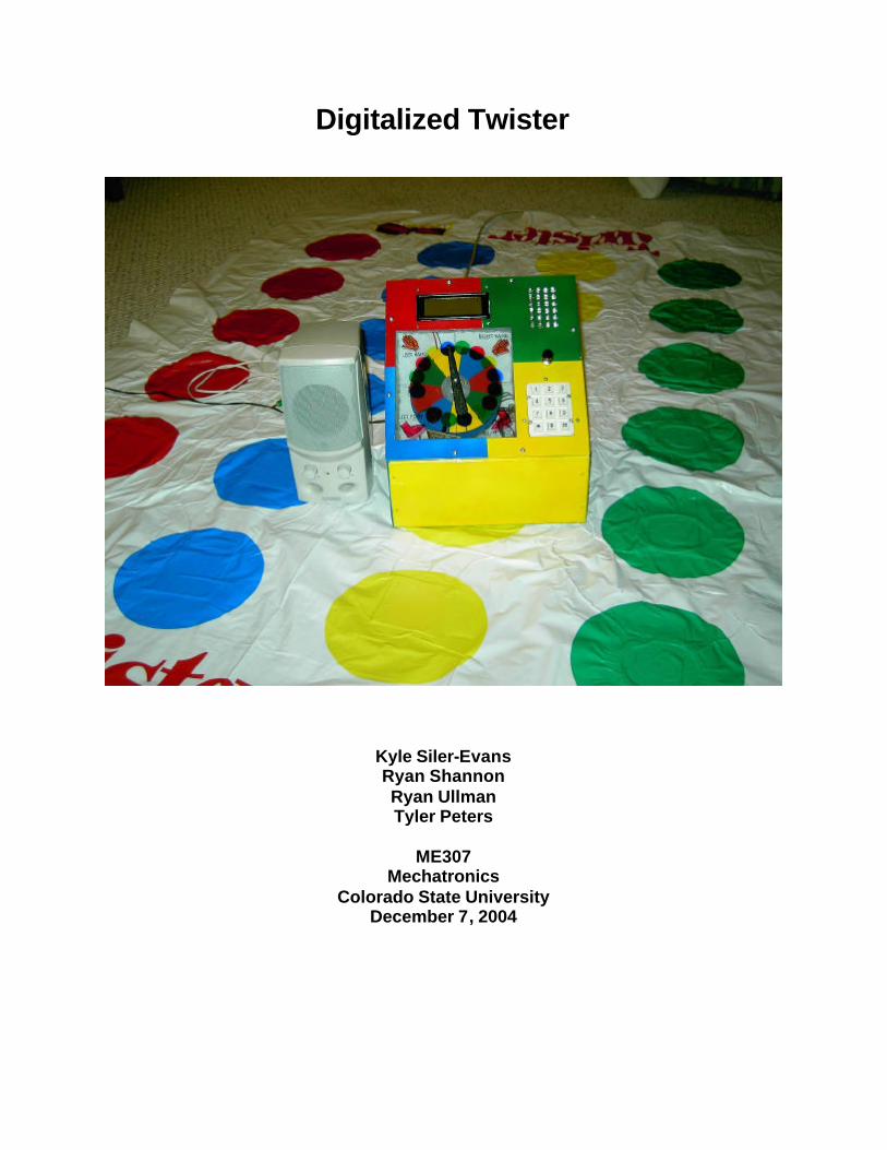
Digitalized Twister
Kyle Siler-Evans Ryan Shannon Ryan Ullman Tyler Peters
ME307
Mechatronics Colorado State University
December 7, 2004

Table of Contents Parts List
Design Summary Design Details Console Design Encoder Flow Chart Game Board Design Design Evaluation Output Display Audio Output Device Manual Data Input Automatic Sensor Input Actuator Logic, Counting, and Control Table of Figures Figure 1 Finished Project Figure 2 Twister Functional Diagram Figure 3 Rough Face-Plate Layout Figure 4 Detailed Face-Plate Layout Figure 5 CNC Machine Figure 6 Graphical Display of Machine Code Figure 7 Face-Plate with Electrical Components Figure 8 Encoder Disk with Photo Interrupters Figure 9 Box Dimensions Figure 10 Solid Model of Box Figure 11 Paper Model of Box Figure 12 Finished Console Base Figure 13 Console Assembly Model Figure 14 Dimensions of Assembly Figure 15 LED Display and Mount Figure 16 Final Circuit Board Figure 17 Encoder Pic Flow Chart Figure 18 Console Face from Behind Figure 19 Game Pad Sensors Figure 20 Number / Color Scheme Layout Figure 21 Back side of the Twister Board

Parts List
Component Allied Electronics Pt #
PIC16F877A N/A PIC16F84A N/A
LCD 670-1116 Keypad 948-7874
Small Protoboard 977-1256 Large Protoboard 661-1550 10 MHz Oscillator 895-0685
4 Mhz Crystal 895-0677 Red Led 670-1245
Green Led 670-1244 Yellow Led 670-1247 Blue Led 670-1071
100 ft Black Wire 708-9891 Speaker 623-2048 2N3904 568-8253 TIP31C 263-0386
5V Voltage Regulator 263-0135 Breadboard 761-0160
1k Ohm resistors 296-6314 330 ohm resistors 296-6310
Twister Board N/A Copper sheet N/A
25 Pin D-sub cable N/A .1 micro farad Caps 507-0352 12V wall transformer 928-9725
Backing for game board N/A Paint N/A
Fasteners N/A Aluminum N/A
Sheet Metal N/A DC Motor 793-0462
Diode 263-1538 Photo Interrupter 263-1361 22 picofarad caps 507-0372

Design Summary
This design will be a take off on the classic Twister game. The game will be automated, and user-interactive. Players will start by entering the number of players using the keypad. The system will not start until the correct number of players is detected in the starting position. Once players get settled, the system with automatically start spinning the wheel. The players’ positions will be determined with a position selection arrow, which is rotated by a DC motor. The final position of the arrow will be known through the use of photo -interrupters. On the game board, electric pressure sensors will detect where each players’ hand or foot is positioned and will highlight that position on a grid of LED’s. After each position selection, the players will have sufficient time to get into the newly assigned positions before the sensors are pooled and logic is performed. If the players’ positions do not correspond to the positions determined by the position selection arrow, a buzzer will sound to signal the end of a round (Figure 1).
Figure 1
Console
Spinner Pointer
Keypad
Reset
2X6 LED Display
LCD Display
Game Board
Speaker

Design Details From the beginning, our design goals focused on converting the classic game of Twister into a fully automated game. Player positions are randomly selected using a DC motor, whose position is tracked with a photo-interrupter circuit; copper switches on the game board track the position of all players and ensure that lazy players don’t drift from the assigned position; a sound chip issues auditory commands for the next move; and a LCD visually displays commands, provides user interface, and menu selection; a numeric keypad allows the user to enter the number of players and maneuver through the sound menu.
In order to track the positions of players on any of the twenty four possible positions (Figure 20), we used custom made normally open switches under each board position. We used a 25 pin serial connector (Figure 16) to electrically connect the game board with the electronics box. We chose a microchip PIC16F877A to be the “Board PIC” because of the large number of input/output pins, which are used to track the status of each of the switches. A 4 x 6 grid of LED’s (corresponding to the 4 x 6 game board) are connected to the board switches to provide a visual display of where players are positioned (Figure 7).
A DC motor was used to spin the ‘position selection arrow’ and two photo-interrupters (Figure 8) were used to track its position. Two CD’s where machined using a CNC mill and used as the photo -interrupter disks (Figure 8). A microchip PIC 16F84A was used to perform the necessary logic to correlate the signals received from the photo-interrupter circuit with game position (e.g. left hand blue). The PIC 16F84A is referred to as the “Encoder PIC”. The “Main PIC” is also a 16F877A PIC and is used as the central hub of our design. A LCD, sound chip, speaker, and numeric keypad are all controlled by the Main PIC. The Main PIC also communicates with the Board PIC and the Encoder PIC using the serial in and serial out commands.
Because we had a large number of input/output pins available to us on the Main PIC, we chose to directly connect the numeric keypad. Using three wires corresponding to the three columns and four wires corresponding to the four rows, the Main PIC is able to detect which buttons are pushed down.
Through out the game, a sound chip issues verbal commands, instructing the
players what to do next. The ISD2560 sound chip has a capacity of up 60 seconds of digitally recorded sound. Sound selection is accomplished by sending a series of pulses to the sound chip, which ‘fast forwards’ to the correct sound. A 4 x 20 LCD is also controlled by the Main PIC and displays information and instructions to the players. For additional aesthetic appeal, we programmed an opening screen which scrolls four lines of the text “Twister Extreme”.

The basic function of Digitalized Twister is best demonstrated by the following example: If the position selection arrow is spun by the DC motor and falls on ‘left hand
blue’, the Encoder PIC will serial out a value of “My_count” equal to 15 to the Main PIC. The Main PIC will send a series of pulses to the sound chip, which will vocally instruct the players to put their left hand on blue. The Main PIC will serial out a number to the Board PIC which implies the number of switches that should be pressed in each column (the number will depend on the number of players, which was selected at the beginning of the game using the numeric keypad, and the position selection from the Encoder PIC) . After a pause allowing the players to move to the correct position, the Board PIC will check if the number of switches pressed down is consistent with what was determined by the Main PIC. If the number is not consistent, the Board PIC will send an interrupt signal to the Main PIC, which will sound a buzzer and restart the program. If the players remain in the correct positions, the Main PIC will not receive an interrupt signal and after a given amount of time will send a signal to the Encoder PIC to start the motor.
As shown in the functional diagram (Figure 2), three PICs were used to serve
specific purposes in Digitalized Twister. The main PIC was used to control the main user communications consisting of the liquid crystal display, sound chip, keypad, and the speaker. The main PIC was also responsible for the bulk of the calculations needed to determine if each player was in the correct position. The main PIC communicates with the encoder PIC and the board PIC serially to complete game functionality. The board PIC’s sole purpose was to accept the serial values of how many switches should be pressed in each color column and constantly checks to make sure the correct number are down. If the correct number of switches were not pressed when they should be the board PIC then signals the main PIC to interrupt the program. This is because the system assumes some player has faulted. The encoder PIC is in charge of the spinner. When signaled from the main PIC, the encoder PIC spins the motor while the position is then read from the position interrupters to determine where the needle is. When the needle has stopped, the PIC then serials out where the needle has stopped to the main PIC. The main PIC then calculates the number of switches the board PIC needs to look for.

Figure 2 Console Design
The first step in the design of the console was making rough sketches of
component layout and spacing to see what arrangement would look best. After this, measurements of all of the electronics were made (such as LCD, LED’s, Keypad, and motor) and laid out to make sure the spacing was indeed correct (Figure 3). Once the necessary corrections were made, a size for the face plate was determined (Figure 4). Research on materials and different milling techniques was done, and we found that an aluminum face plate with a sheet metal box would be easy, cost effective, and aesthetic. It was also found that since there were precise cuts and many holes to be drilled, milling on the CNC (Figure 5) would save time. Once this was realized the face-plate was drawn in Pro-Engineer and converted to a drawing file. TekSoft CAD_CAM: ProCam 2003 Plus 2D was then used to convert the drawing into machine code for the CNC (Figure 6).
The face plate was cut using the CNC and the electronics were put in place to assure proper fit (Figure 7). The face plate was then taped off and painted. After the face plate was finished the encoder disks were milled (Figure 8). The disks were made of CD material. The milling also utilized the help of the CNC in order to provide accurate

spacing. The encoder disks were painted in order to enhance appearance, as well at to make sure no light was able to travel from one side of the disk to the other.
The final step in the manufacturing process was to make a box to hold the face plate as well as the actual components (Figure 9, 10). Care had to be taken to be sure the motor and the encoder disks would have enough room to fit in the box. We also had to be sure the rest of the components would fit into the console without interfering with each others fit or function. Because this was a first time working with sheet metal a paper diagram was constructed to give an actual space for the components to be tested to assure fit (Figure 11). Once we were sure the components would fit, the outline was traced and the box was cut and bent into shape. Once the shape was formed pop-rivets were used to secure the box’s sides and holes were drilled in the top and back to fit the motor, sound cord, power cord, and the connection for the board. After everything was drilled and fitted the box was painted to match the twister theme and the components were finally placed and secured in the console (Figure 12).
Figure 3
Rough Face-Plate Layout

Figure 4
Detailed Face-Plate Layout to be converted
into Machine Code

Figure 5
CNC Mill Machine Used To Mill Faceplate and Encoder discs

Figure 6
Graphical Display of Machine Code on the
CNC

Figure 7
Keypad
LED display
LCD display
LED connector

Figure 8
Encoder Discs
Photo Interrupters
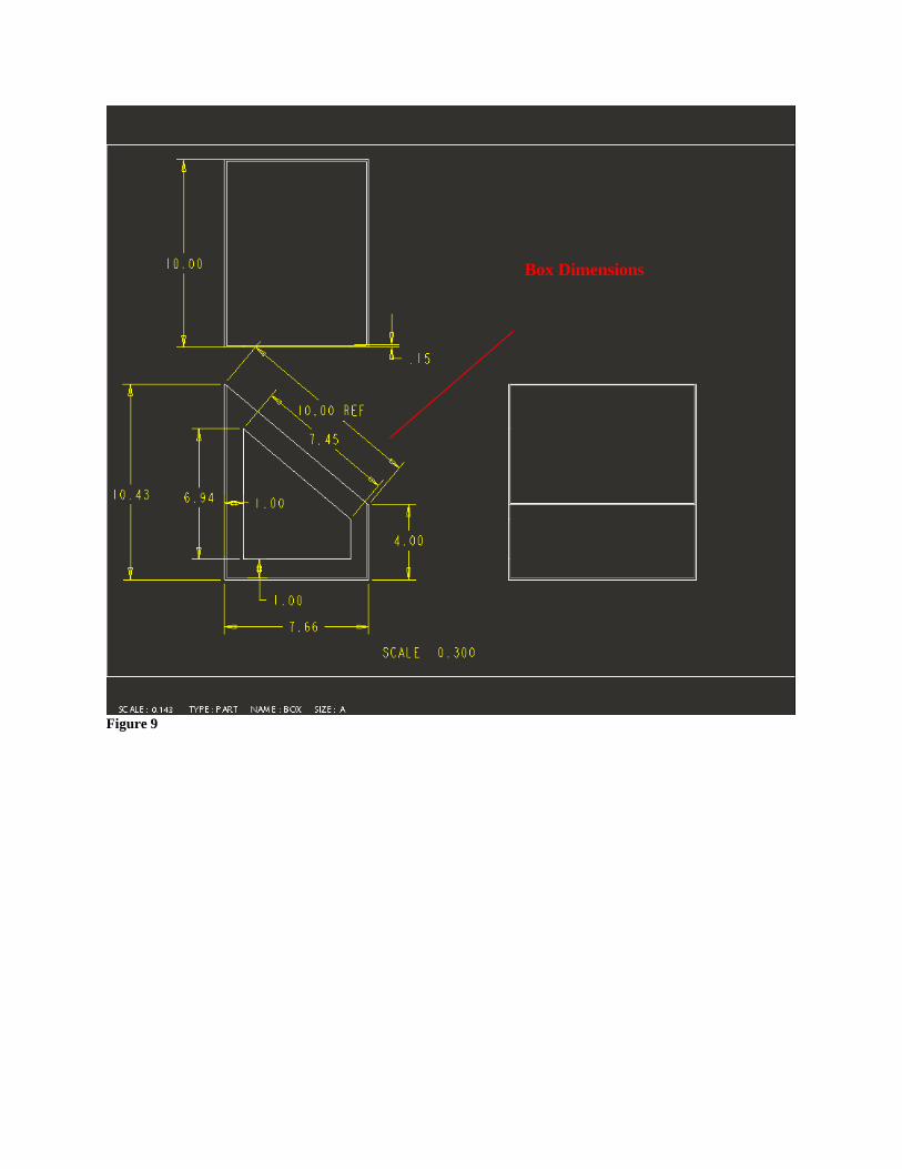
Figure 9
Box Dimensions

Figure 10
Solid Model of Box

Figure 11
Paper Model for box

Figure 12
Finished Console Base

Figure 13
Console Assembly

Figure 14
Dimensions of Assembly

Figure 15
LED Display Panel
LED Connector
Mounting Tape

Figure 16 Encoder
12 Volt DC supply
25 pin D Sub board Connection cable

Figure 17

Figure 18 Game Board Design
We desired that our Twister game board have a number of design considerations. First, we wished to use a standard Twister game board. Secondly, we wanted to maintain the fold-ability of the original game board while successfully placing the appropriate sensors necessary to communicate with our PIC’s. In addition, we had to consider cost. Finally, we needed to utilize a sensor that would not fail due to fatigue given the cyclic loading natural of the game. What was finally implemented successfully fulfilled our design criteria as stated above.
Given the design criteria for our sensors we had to focus on something simple yet responsive. What we ended up implementing in our final design consisted of two three by three inch parallel copper plates separated by a standard piece of computer paper with a rectangle cut out in the center of the square-cut paper. The cut out allowed the circuit to be completed when small amounts of pressure was applied to the plates, all the while remaining open when uncompressed, and remaining responsive under cyclic loading conditions . Ideally, we would have liked to use copper circles cut to the same size as a colored circle on the original game board. However, due to the high
Keypad Connector
LCD Connector
Holes for LED Board LCD
Keypad

costs of copper plating and difficulty in manufacturing, we elected to use smaller square shaped sensors. A standard twister board consists of 24 circles, thus 48 square plates had to be manufactured (Figure 21). A wire was soldered to each of these 48 plates. (Figure 19)
Figure 19 One of the two wires in each sensor was tied to ground while the other was connected to a specific wire in the 25 Pin D-sub (Figure 21). Each pin number on the 25 Pin D-sub was connected to one of the sensors and a diagram was generated and used in the
Copper Plate with Soldered Wire
Computer Paper with rectangular cut out
Copper Plate without Soldered Wire
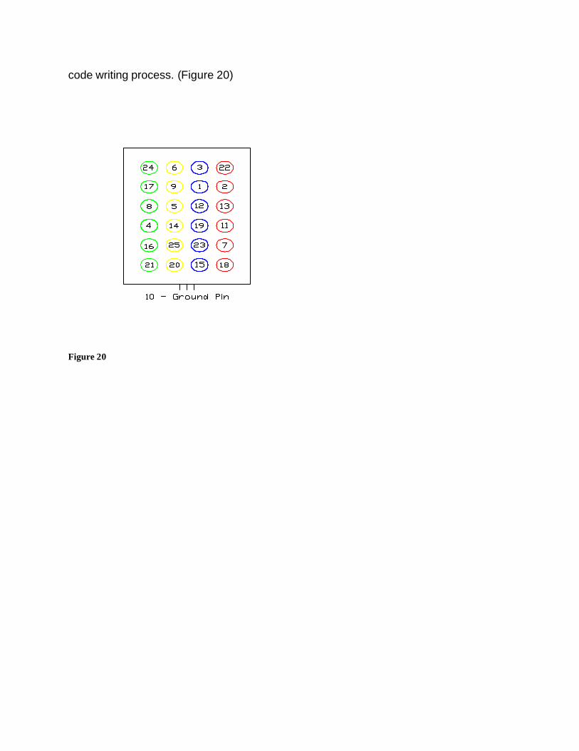
code writing process. (Figure 20)
Figure 20

Figure 21 Design Evaluation
Digitalized Twister was designed around the functional element categories of Colorado State University’s Mechatronics course. The title of the category and what was implemented in Digitalized Twister to meet the requirements are listed below. Output display:
• LCD: A LCD is used throughout the game to ask for user input and display messages to the players.
• LED: A grid of LEDs will display the positions of players on the game board. Audio output device:
25 Pin D-sub 1 of 24 pressure sensors

• ?ISD2560 Sound Chip: Used to create 18 synthesized voice sounds used for directing the players’ movements.
• Buzzer: internal speaker provides sound for when a player falters and when the wheel spins.
Manual Data input:
• Numerical Keypad: At the start of the game, the system requires that the number of players be entered; this was accomplished with a numerical keypad.
• Pressure Buttons: 24Custom made buttons used to track positions of players on the game board.
Automatic sensor input:
• Two Photo-interrupters: Two photo-interrupters used to track the position selection arrow.
Actuator:
• DC Motor: One DC motor was used to rotate the position selection arrow. Logic, Counting and Control:
• Digitalized Twister is a ‘smart’ version of the classic game we all know and love. In order for our Digitalized Twister game to successfully function, we relied heavily on the logic, counting, and control provided by our peripheral interface controller (PIC).
Our design used two photo-interrupters to track the resting position of the position selection arrow. The first photo-interrupter was used to determine which of the 16 possible segments (left or right hand or foot on red, yellow, green, or blue) the arrow falls on. This was tracked using a counting variable. Rather than continually incrementing up for multiple rotations, we used a second photo-interrupter to zero the stored value every revolution. The second photo-interrupter will also save us the trouble of defining the starting position of the selection arrow. Our successful photo-interrupter system required a carefully thought out program using counting and logic. In addition to counting and logic we required two 40 pin PICs to go along with one 18 pin PIC. These PICs are required to serial to each other throughout the cycle of our game. Thus, our logic system is quite extensive. Additional use of logic, counting, and control was used in tracking the players’ positions on the board. Because of our photo-interrupter system, the PIC will ‘know’ which positions on the board should be occupied. If a player fails to get into, or maintain, the proper position, Digitalized Twister detects the failure and activates a buzzer, signaling the end of the round.

Microcontroller code 'Main Pic Code Include "Modedefs.Bas" 'include the mode definitions used for the serial commands Define OSC 10 'set oscillator speed to 10 Mhz 'Below Code Sets The registers of the pic to turn off/on special features ADCON1=%00000000 'turn off pic A/D OPTION_REG=%00000000 'turn on pull up resistors CMCON=%00000000 'turn off comparators ADCON0=%00000000 'A/D 'registers used in the pic16f88 during testing that needed to be set 'T1CON=%00000000 'TIMER1 'T2CON=%00000000 'TIMER2 'CCP1CON=%00000000 'RCSTA=%00000000 'ANSEL=%00000000 'CVRCON=%00000000 'Setting the I/O Pins TRISA=%100010 'Set port A I/O TRISB=%11110001 'set port B I/O TRISC=%01101000 'Define all but bit 7 on port c as outputs TRISD=%00010000 'Define port d as outputs TRISE=%00000000 'On Interrupt goto myint 'INTCON=$90 players Var byte 'Define # of players variable num var byte snd var byte[2] snd2 var byte n var byte nd2 var byte sound_pinin var PORTD.4 sound_pinout var PORTC.3 'define serial ports 'used for board pic serialing bpsert var PORTA.3 bpserial var PORTC.0 sred var byte sgreen var byte syellow var byte sblue var byte 'Defines Values needed for lcd output I Con 254 CLR Con 1 LINE1 Con 128 LINE2 Con 192 LINE3 Con 148 LINE4 Con 212 LCD Var PORTA.0

'used for encoder pic serialing epserialtime var PORTC.7 'timing wire for serial between encoder and main pics epserial var PORTC.6 'serial wire between main and encoder pic position var byte 'position variable stores the value serialed from encoder pic 'Pin assignments for the keypad row1 Var PORTB.7 row2 Var PORTB.6 row3 Var PORTB.5 row4 Var PORTB.4 col1 Var PORTB.3 col2 Var PORTB.2 col3 Var PORTB.1 key var byte 'variable for the key pressed in the kepad subroutine 'Sound chip port definitions CE var PORTD.2 PR var PORTD.3 PD var PORTC.4 EOM var PortC.5 High CE High PD waste var word 'Interrupt routine 'define the mode settings of the ISD2560 Sound chip to the portd pins M0 var PORTD.0 M4 Var PORTD.1 sond var byte PortD.7=0 'Set all the mode pins for the sound chip to zero to begin with Low M0 Low M4 'calculation variables for the number of switches that should be down LFN var byte RFN var byte LHN var byte RHN var byte LF var byte RF var byte LH var byte RH var byte LHred var byte RHred var byte RFred var byte LFred var byte totalred var byte LHgreen var byte

RHgreen var byte RFgreen var byte LFgreen var byte totalgreen var byte LHyellow var byte RHyellow var byte RFyellow var byte LFyellow var byte totalyellow var byte LHblue var byte RHblue var byte RFblue var byte LFblue var byte totalblue var byte soundnum var byte 'pause to initialize the lcd Pause 2000 'Display twister extreme on lcd x var byte serout LCD, N9600, [I, CLR] pause 500 serout LCD,N9600, [I,LINE1," *TWISTER EXTREME* "] serout LCD,N9600, [I,LINE2," *TWISTER EXTREME* "] serout LCD,N9600, [I,LINE3," *TWISTER EXTREME* "] serout LCD,N9600, [I,LINE4," *TWISTER EXTREME* "] 'scroll text across the LCD for x = 1 to 39 PAUSE 200 serout LCD, n9600, [I, 24] next x pause 1000 ' pause for 2 seconds initial: 'Display initial selection screen on lcd serout LCD,N9600,[I,CLR,I,LINE1," Keypad Selection: "] serout LCD,N9600,[I,LINE2," 1 - Sound Setup "] serout LCD,N9600,[I,LINE3," 4 - Play Twister "] GoSub keypad 'goto keypad subroutine If key=1 Then goto setup1 If key=4 then goto game setup1: 'Display sound setup screen serout LCD,N9600,[I,CLR,I,LINE1," Sound Setup: "] serout LCD,N9600,[I,LINE2," 1 - Play "] serout LCD,N9600,[I,LINE3," 4- Record "]

serout LCD,N9600,[I,LINE4," *- Exit "] Gosub keypad 'goto keypad subroutine If key=1 Then goto splay IF key=4 Then goto srecord If key=10 Then goto initial srecord: High M4 'set mode as consecutive addressing sond=1 'sets sond variable to one to begin with srecord1: serout LCD,N9600,[I,CLR,I,LINE1," Press * To Start "] serout LCD,N9600,[I,LINE2," Recording and * "] serout LCD,N9600,[I,LINE3," at end of Recording"] Serout LCD,N9600,[I,LINE4," Sound ","#",#sond," #-Exit "] pause 200 Gosub keypad 'goto keypad subroutine record: LOW PD 'turn on the sound chip LOW PR 'set the sound chip to record mode Gosub keypad 'goto keypad subroutine If key=10 Then goto startr If key=11 Then Goto setup1 Gosub keypad 'goto keypad subroutine startr: LOW CE 'Set the CE pin on the sound chip to low to begin recording serout LCD,N9600,[I,CLR] pause 100 serout LCD,N9600,[I,LINE2," Recording "] pause 200 'pause for 200 ms startr1: Gosub keypad 'goto keypad subroutine If key=10 Then HIGH CE 'set the CE pin on the sound chip to high to end recording sond=sond+1 'increase the sound variable by one goto srecord1 'go back to start of recording section Else goto startr1 endif endr: 'end the recording section HIGH CE 'set the CE pin to high to end High PD 'turn the sound chip off Low M4 ' turn of the consectutive addressing mode bit Goto setup1 'return to the sound setup screen splay: High M4 serout LCD,N9600,[I,CLR,I,LINE2," Enter Two Digit "] serout LCD,N9600,[I,LINE3," Sound Number "] Serout LCD,N9600,[I,LINE4+9]

pause 500 'goto and store keypad values entered to play specified sound number For num=0 to 1 'loop for two key presses Gosub keypad 'goto keypad subroutine snd[num]=key 'store the key pressed in an array pause 200 'pause for 200 ms to debounce serout LCD,N9600,[snd[num]+48] 'display the number pressed next snd2=snd[1]+10*snd[0] 'convert the array to a base 10 number pause 200 'pause for 200 ms LOW PD 'turn on sound chip HIGH PR 'set to play mode nd2=snd2-1 'If sound number choosen is 1 or 0 then play first recording If snd2<2 Then LOW CE goto play Endif 'message selected is greater than one so use message cueing on sound chip High M0 'turn on message cueing For n=1 to nd2 Pulsout CE, 10 'pulse CE pin to fastfoward Pulsin EOM,0,waste 'wait for EOM pulse before continuing next 'next n Low M0 'turn off message cueing play: low CE serout LCD,N9600,[I,CLR] 'clear the lcd pause 100 'pause for 100 ms serout LCD,N9600,[I,LINE2," Playing "] While EOM=1 'pause while EOM pin is high WEND 'end while High PD 'turn off sound chip Low M4 LOW M0 High CE 'turn off consective play on sound chip Goto setup1 Game: 'Display Enter Number Of Players On Keypad serout LCD,N9600,[I,CLR,I,LINE1," Enter Number "] serout LCD,N9600,[I,LINE2," Of Players "] serout LCD,N9600,[I,LINE3," On Keypad "] serout LCD,N9600,[I,LINE4+9] soundnum=17 gosub say players=0 'set players variable = to zero to begin with 'keypad polling loop until a number other then zero is pressed
While players=0 Gosub keypad players=key WEND serout LCD,N9600,[#players] Pause 2000 'pause for 2 seconds 'Display message for begining instructions to players serout LCD,N9600,[I,CLR,I,LINE1," Players Put "] serout LCD,N9600,[I,LINE2," Left Foot On Red "] serout LCD,N9600,[I,LINE3," Right Foot On Blue "] serout LCD,N9600,[I,LINE4,"Within Next 30 Secs"] soundnum=18 gosub say Pause 3000 'Pause for 30 secs for players to get on correct postition 'begin the main program by serialing the comparison values for the switches 'that should be activated to the board pic and comparing them to be sure the 'players are on the correct position. Then the game will begin. 'set and calculate what the number of swithches pressed should be for the first time sred=players sblue=players sgreen=0 syellow=0 'values of variables to begin with LF=1 RF=4 RH=0 LH=0 LFN=1 RFN=4 RHN=0 LHN=0 low bpserial high bpsert pause 100 low bpsert Serout bpserial,N9600,[sred] pause 100 low bpserial pause 100 Serout bpserial,N9600,[sgreen] pause 100 low bpserial pause 100 Serout bpserial,N9600,[syellow] pause 100 low bpserial pause 100 Serout bpserial,N9600,[sblue] pause 100 low bpserial

'serial out the number of switches that should be pressed in each column ' to the board pic for comparison pause 2000 'pause Goto respin 'begin the main loop of the twister program loop: low bpserial High bpsert 'set board pic timing wire to high pause 100 low bpsert Serout bpserial,N9600,[sred] pause 100 low bpserial pause 100 Serout bpserial,N9600,[sgreen] pause 100 low bpserial pause 100 Serout bpserial,N9600,[syellow] pause 100 low bpserial pause 100 Serout bpserial,N9600,[sblue] pause 100 low bpserial 'serial out the number of switches that should be pressed in each column ' to the board pic for comparison pause 1000 'pause to give board pic time to pause program before allowing players to move to new postions 'Controls what the sound chips tells the players to move to where soundnum=position+1 gosub say pause 5000 'pause the program for 15 seconds inbetween each move respin: High epserialtime pause 500 'pause for 500 ms Low epserialtime serout LCD,N9600,[I,CLR,I,Line1," Waiting "] INPUT epserialtime While epserialtime=0 IF (sound_pinin==1) Then Sound sound_pinout,[100,10] ENDIF WEND OUTPUT epserialtime Serin epserial,N2400,position 'serial in the encoder postion for the encoder pic serout LCD,N9600,[I,CLR,I,Line1,#sred]

serout LCD,N9600,[I,Line2,#sgreen] serout LCD,N9600,[I,Line3,#syellow] serout LCD,N9600,[I,Line4,#sblue] RHN=RH LHN=LH RFN=RF LFN=LF 'updates based on the encoder pic postion variable ' red =1, green=2, yellow=3, blue=4 IF position==0 Then RHN=2 IF position==1 Then RHN=1 IF position==2 Then RHN=3 IF position==3 Then RHN=4 IF position==4 Then RFN=2 IF position==5 Then RFN=1 IF position==6 Then RFN=3 IF position==7 Then RFN=4 IF position==8 Then LFN=2 IF position==9 Then LFN=1 IF position==10 Then LFN=3 IF position==11 Then LFN=4 IF position==12 Then LHN=2 IF position==13 Then LHN=1 IF position==14 Then LHN=3 IF position==15 Then LHN=4 LHred=0 RHred=0 RFred=0 LFred=0 LHgreen=0 RHgreen=0 RFgreen=0 LFgreen=0 LHyellow=0 RHyellow=0 RFyellow=0 LFyellow=0 LHblue=0 RHblue=0 RFblue=0 LFblue=0 IF LHN==1 Then LHred=players IF LFN==1 Then LFred=players IF RHN==1 Then RHred=players IF RFN==1 Then RFred=players
totalred=LHred+LFred+RHred+RFred IF LHN==2 Then LHgreen=players IF LFN==2 Then LFgreen=players IF RHN==2 Then RHgreen=players IF RFN==2 Then RFgreen=players totalgreen=LHgreen+LFgreen+RHgreen+RFgreen IF LHN==3 Then LHyellow=players IF LFN==3 Then LFyellow=players IF RHN==3 Then RHyellow=players IF RFN==3 Then RFyellow=players totalyellow=LHyellow+LFyellow+RHyellow+RFyellow IF LHN==4 Then LHblue=players IF LFN==4 Then LFblue=players IF RHN==4 Then RHblue=players IF RFN==4 Then RFblue=players totalblue=LHblue+LFblue+RHblue+RFblue IF totalred<=6 and totalgreen<=6 and totalyellow<=6 and totalblue<=6 Then sred=totalred sgreen=totalgreen syellow=totalyellow sblue=totalblue LF=LFN RF=RFN LH=LHN RH=RHN Goto loop Else serout LCD,N9600,[I,CLR] serout LCD,N9600,[I,Line1,#totalred] serout LCD,N9600,[I,Line2,#totalgreen] serout LCD,N9600,[I,Line3,#totalyellow] serout LCD,N9600,[I,Line4,#totalblue] pause 5000 Goto res pin Endif 'myint: 'Goto game End 'ends the program 'Keypad Subroutine keypad: key=13 'Set Initial variable so on keypress the loop exits 'keypad polling loop until button is pressed While key=13 'check column 1 Low col1 High col2

High col3 If (row1==0) Then key=1 If (row2==0) Then key=4 If (row3==0) Then key=7 If (row4==0) Then key=10 'check column 2 High col1 Low col2 High col3 If (row1==0) Then key=2 If (row2==0) Then key=5 If (row3==0) Then key=8 If (row4==0) Then key=0 'Check column 3 High col1 High col2 Low col3 If (row1==0) Then key=3 If (row2==0) Then key=6 If (row3==0) Then key=9 If (row4==0) Then key=11 WEND Return say: LOW PD 'turn on sound chip HIGH PR 'set to play mode 'If sound number choosen is 1 or 0 then play first recording If soundnum=2 Then LOW CE 'play sound pause 200 While EOM=1 'wait until done playing sound WEND HIGH PD 'turn off sound chip High CE 'reset chip enable/play pin Else 'message selected is greater than one so use message cueing on sound chip High M0 High M4 'turn on message cueing For n=2 to soundnum Pulsout CE, 10 'pulse CE pin to fastfoward Pulsin EOM,0,waste 'wait for EOM pulse before continuing next 'next n Low M0 'turn off message cueing Low CE 'Play clip pause 200 While EOM=1 WEND High PD 'turn off sound chip Low M4 'turn off consecutive play LOW M0 'turn off message cueing High CE 'turn off consective play on sound chip endif Return 'return to program

'photo-interrupter 'declare variables Include "Modedefs.Bas" 'include the mode definitions used for the serial commands Green_LED var PORTB.0 Red_LED var PORTB.1 Yellow_LED var PORTB.2 Blue_LED var PORTB.3 My_count var BYTE 'counting variable count_int var PORTA.0 'counting interrupter zero_int var PORTA.1 'zero interrupter Motor_input var PORTA.2 Motor_output var PORTA.4 I var WORD 'iterative counting variable for the motor Ser_out var PORTB.7 Randm var WORD Stable_count var WORD Stop_I var WORD TRISA = %11110111 'port A –inputs TRISB = %00000000 'port B -outputs 'Initialize variables/ports Low Motor_output Low PORTB.0 Low PORTB.1 Low PORTB.2 Low PORTB.3 low SER_out My_count = 0 I = 0 Stable_count = 0 Stop_I = 0 Pause 100 Goto Loop2 Loop: 'motor If (Motor_input == 1) Then 'motor input/output I = I + 1 Random Randm Stop_I = 14000 + Randm/11 Endif If ((I >= 1) AND ( I < Stop_I )) Then High Motor_output I = I + 1 Else Low Motor_output I = 0

Endif 'interrupter If (Count_int = 1) Then 'count interrupter My_count = My_count + 1 Stable_count = 0 HIGH PORTB.6 pause 10 LOW PORTB.6 Endif While (Count_int = 1) High Motor_output 'ensures the motor does not stop here Wend If (Zero_int = 1) Then 'zero interrupter My_count = 0 Stable_count = 0 Endif While (zero_int = 1) High Motor_output Wend Stable_count = Stable_count + 1 If (Stable_count > 4000) Then OUTPUT Motor_input Motor_input=1 pause 500 LOW Motor_input Input Motor_input Serout Ser_out,N2400,[My_count] High Blue_led : High Red_led : High Green_led : High yellow_led Pause 200 Low Blue_led : Low Red_led : Low Green_led : Low yellow_led Stable_count = 0 Goto loop2 Endif If (My_count = 0) Then High Green_led Else Low Green_led Endif If (My_count = 1) Then High Red_led Else Low Red_led Endif If (My_count = 2) Then High Yellow_led Else Low Yellow_led Endif

If (My_count = 3) Then High Blue_led Else Low Blue_led Endif If (My_count = 4) Then High Green_led Else Low Green_led Endif If (My_count = 5) Then High Red_led Else Low Red_led Endif If (My_count = 6) Then High Yellow_led Else Low Yellow_led Endif If (My_count = 7) Then High Blue_led Else Low Blue_led Endif If (My_count = 8) Then High Green_led Else Low Green_led Endif If (My_count = 9) Then High Red_led Else Low Red_led Endif If (My_count = 10) Then High Yellow_led Else Low Yellow_led Endif If (My_count = 11) Then High Blue_led Else Low Blue_led Endif If (My_count = 12) Then High Green_led Else

Low Green_led Endif If (My_count = 13) Then High Red_led Else Low Red_led Endif If (My_count = 14) Then High Yellow_led Else Low Yellow_led Endif If (My_count = 15) Then High Blue_led Else Low Blue_led Endif If (My_count > 16) Then 'should never be the case My_count = 0 Endif goto loop End 'loop Loop2 I = 0 Stable_count = 0 Stop_I = 0 Low PORTB.0 Low PORTB.1 Low PORTB.2 Low PORTB.3 If (Motor_input = 1) Then Goto loop Else Goto Loop2 Endif End 'boardpic.bas Include "Modedefs.Bas" 'include the mode definitions used for the serial commands Define OSC 20 'Below Code Sets The registers of the pic to turn off/on special features ADCON1=7 'turn off pic A/D INTCON=7 'turn off interrupts CMCON=7 'turn off comparators

ADCON0=7 'turn off pic A/D 'set the ports as I/O TRISA=%111111 'Set port A I/O TRISB=%000111111 'Set port B I/O TRISC=%000111111 'Set port B I/O TRISD=%100111111 'Set port B I/O TRISE=%000000011 'Set port B I/O 'registers used in the pic16f88 during testing that needed to be set T1CON=%00000000 'TIMER1 T2CON=%00000000 'TIMER2 CCP1CON=%00000000 RCSTA=%00000000 'ANSEL=%00000000 CVRCON=%00000000 'Defines the board switches to the ports of the pic 'Set PortA as the red column SW1 Var PortA.0 SW2 Var PortA.1 SW3 Var PortA.2 SW4 Var PortA.3 SW5 Var PortA.4 SW6 Var PortA.5 'Set PortB as the green column SW7 Var PortB.0 SW8 Var PortB.1 SW9 Var PortB.2 SW10 Var PortB.3 SW11 Var PortB.4 SW12 Var PortB.5 'Set portc as the yellow column SW13 Var PortC.0 SW14 Var Port C.1 SW15 Var PortC.2 SW16 Var PortC.3 SW17 Var PortC.4 SW18 Var PortC.5 'Setportd as the blue column SW19 Var PortD.0 SW20 Var PortD.1 SW21 Var PortD.2 SW22 Var PortD.3 SW23 Var PortD.4 SW24 Var PortD.5 'Define timing and serial Pins serialtime Var PORTE.0 ser Var PORTE.1 error Var PORTE.2 Low error 'set error pin to low to begin with 'define column addition variables

redtot var byte greentot var byte yellowtot var byte bluetot var byte 'define serial totals from mainpic sred var byte sgreen var byte syellow var byte sblue var byte 'set the variable values to begin with sred=0 sgreen=0 syellow=0 sblue=0 Start: HIGH PORTB.6 'serial in the values for the first time players get on board Serin ser,N9600,sred Serin ser,N9600,sgreen Serin ser,N9600,syellow Serin ser,N9600,sblue LOW PORTB.6 switchcheck: pause 500 IF (serialtime==0) Then 'Add up the total number of switches per column that are high to compare to redtot=SW1+SW2+SW3+SW4+SW5+SW6 greentot=SW7+SW8+SW9+SW10+SW11+SW12 yellowtot=SW13+SW14+SW15+SW16+SW17+SW18 bluetot=SW19+SW20+SW21+SW22+SW23+SW24 'checks to see if the totals are what they should be If (redtot==sred) and (greentot==sgreen) and (yellowtot==syellow) and (bluetot==sblue) Then Goto switchcheck Else 'The totals do not match and therefore someone screwed up High error pause 5000 low error Goto start Endif Else 'serial in new total switches that should be pressed for each column High PortB.6 Serin ser,N9600,sred Serin ser,N9600,sgreen Serin ser,N9600,syellow Serin ser,N9600,sblue Pause 500

Low PORTB.6 'pause 10000 ' Pause for ten seconds so that players can move Goto switchcheck ' Go back to loop endif End 'end the program


