33
Dimensioning
| Date post: | 13-Dec-2015 |
| Category: |
Documents |
| Upload: | vanessa-shelton |
| View: | 224 times |
| Download: | 1 times |
Dimensioning
Dimensions• Dimensions are used to describe the sizes and
relationships between features in your drawing.• Dimensions are used to manufacture parts and to
inspect the resulting parts to determine if they are acceptable.
• Drawings with dimensions and notes often serve as construction documents and legal contracts.
• ANSI Y14.5M-1994 is the current standard. Other standards may apply.

Standards for Your Career Field
• Standards are different in different career areas.
• Most of the examples in this course will be of mechanical parts.
• Civil, Electrical, Construction, and other areas follow similar practices, but sometimes with less need for precision in measurements.
• Dimensioned drawings are a part of a contractual document.

VocabularyDimension line, Extension line, Leader, Dimension
offset or gap, Centerline,Finish mark, Dimension value
Baseline dimensioning, Chained dimensioning
Tolerance
Definition: The total allowable variation an acceptable part can have from the
specified dimension.
The less variation allowed, the more the part will cost to make.
3 Things for Good Dimensioning
• Good technique of dimensioning
• Good choice of dimensions
• Good placement of dimensions
Dimensioning Technique
• describes how the dimensions in your drawing should look.
• defined by various standards like ANSI Y14.5-1994.
• help you create dimensions that are plainly visible and can be easily interpreted.
• specifies sizes for creating dimensions relative to the paper size of your final plot.
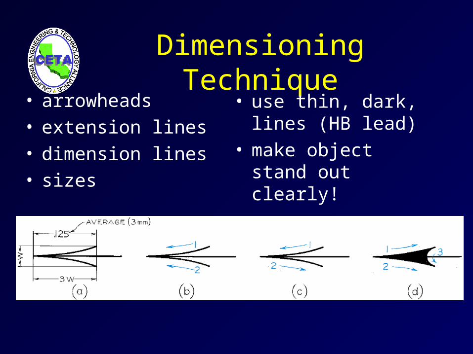
Dimensioning Technique• arrowheads• extension lines• dimension lines• sizes
• use thin, dark, lines (HB lead)
• make object stand out clearly!

Dimension Values
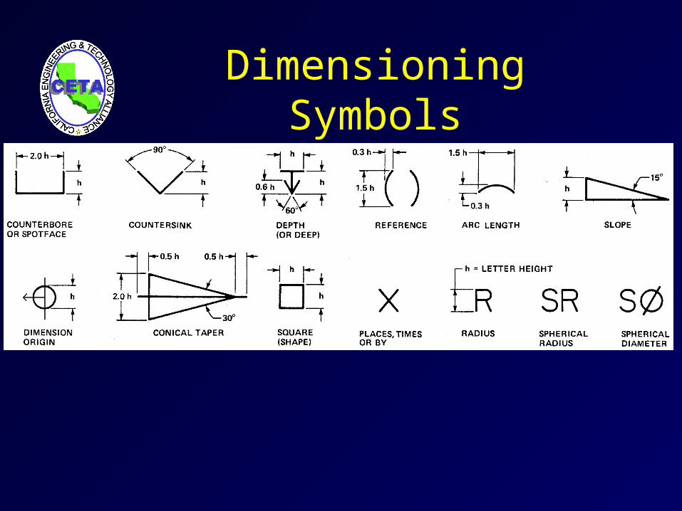
Dimensioning Symbols
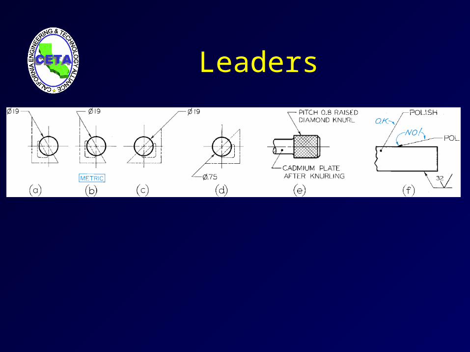
Leaders

Orientation forDimension Values
• Unidirectional: – read horizontally from bottom of sheet
• Aligned:– align with dimension line and read from bottom or
right side of sheet

Unidirectional Orientation
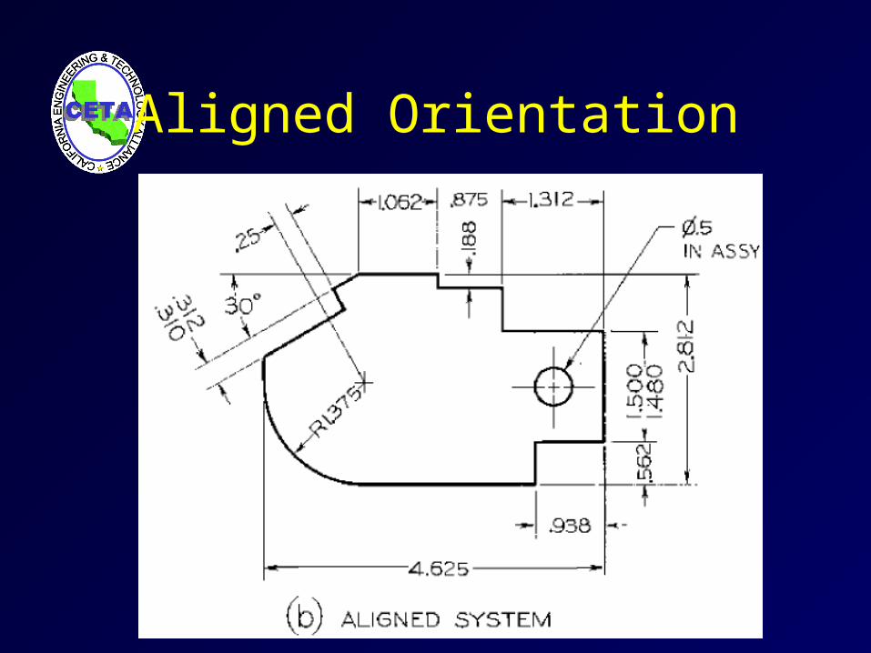
Aligned Orientation
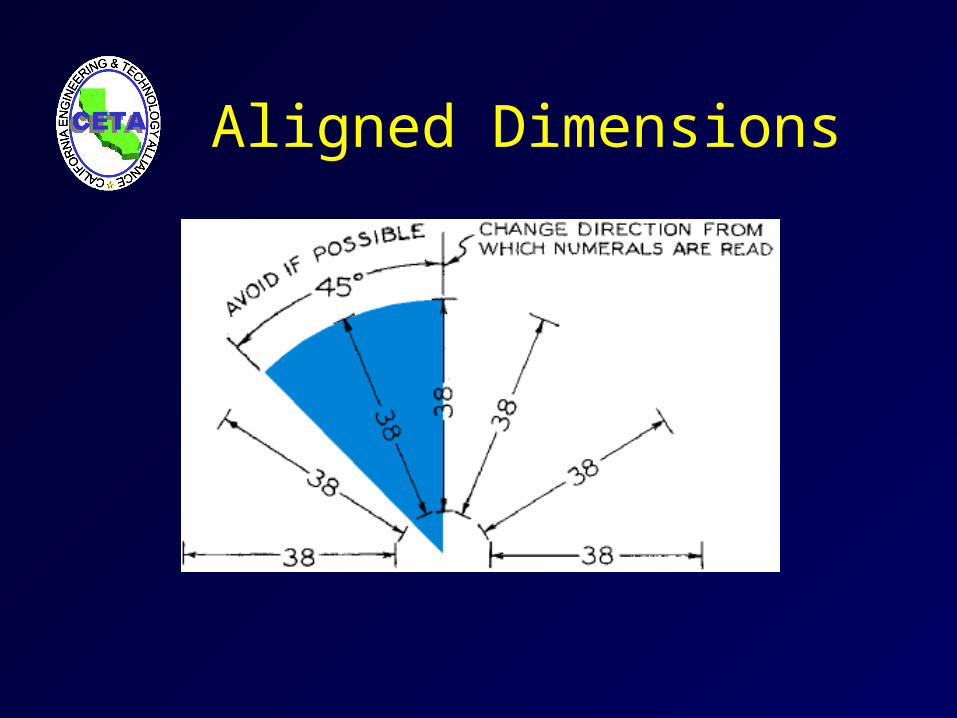
Aligned Dimensions
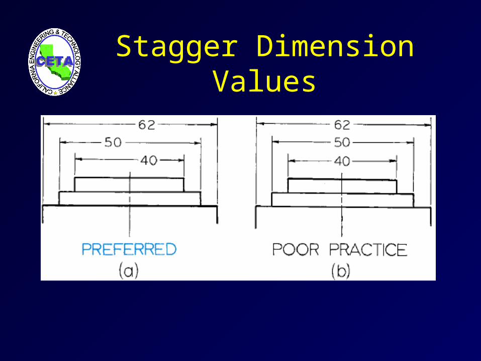
Stagger Dimension Values
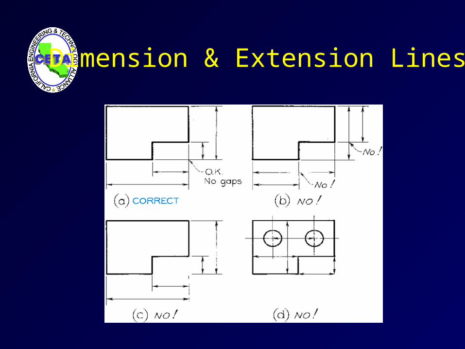
Dimension & Extension Lines
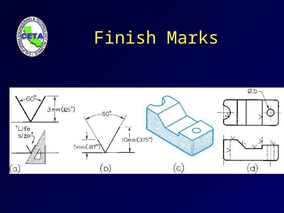
Finish Marks
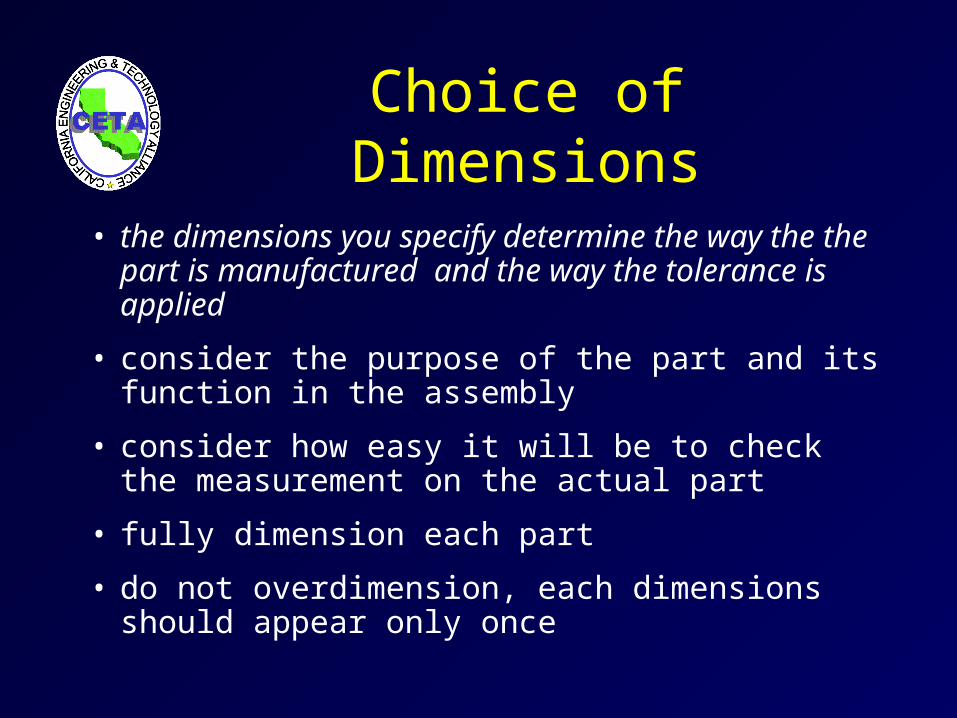
Choice of Dimensions
• the dimensions you specify determine the way the the part is manufactured and the way the tolerance is applied
• consider the purpose of the part and its function in the assembly
• consider how easy it will be to check the measurement on the actual part
• fully dimension each part
• do not overdimension, each dimensions should appear only once
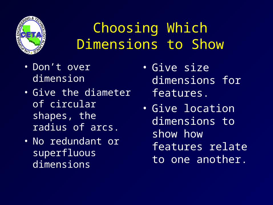
Choosing Which Dimensions to Show
• Don’t over dimension• Give the diameter of
circular shapes, the radius of arcs.
• No redundant or superfluous dimensions
• Give size dimensions for features.
• Give location dimensions to show how features relate to one another.

Mating Dimensions
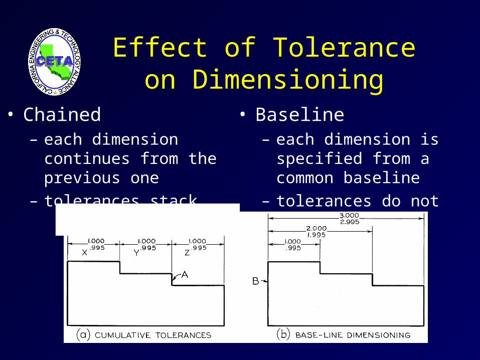
Effect of Tolerance on Dimensioning
• Baseline– each dimension is specified
from a common baseline
– tolerances do not stack
• Chained– each dimension continues
from the previous one
– tolerances stack
Units
• Fractional Inch
• Decimal inch dimensions are typically specified to 2 decimal places.
• Metric values are typically given in whole millimeters or to one decimal place.
Placement of Dimensions• Rules-of-thumb for dimension placement help ensure
that others will be able to interpret your drawing
• Where placement practices conflict, remember that your goal is to clearly communicate the purpose of the drawing. Use the practice you feel will make the drawing easy to understand.
Placement Practices
• Avoid dimensioning on object (face of part).
• Avoid dimensioning to hidden lines.
• Place dimensions between views when possible.
• Don’t “float” dimensions.
• Group dimensions around a central view.
• Place dimensions where feature shows shape.
• Dimension from or between machined surfaces
• Give overall dimensions where possible.
• Don’t dimension to rectangular view centerlines.
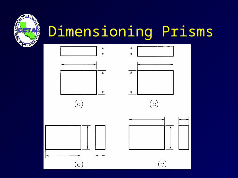
Dimensioning Prisms
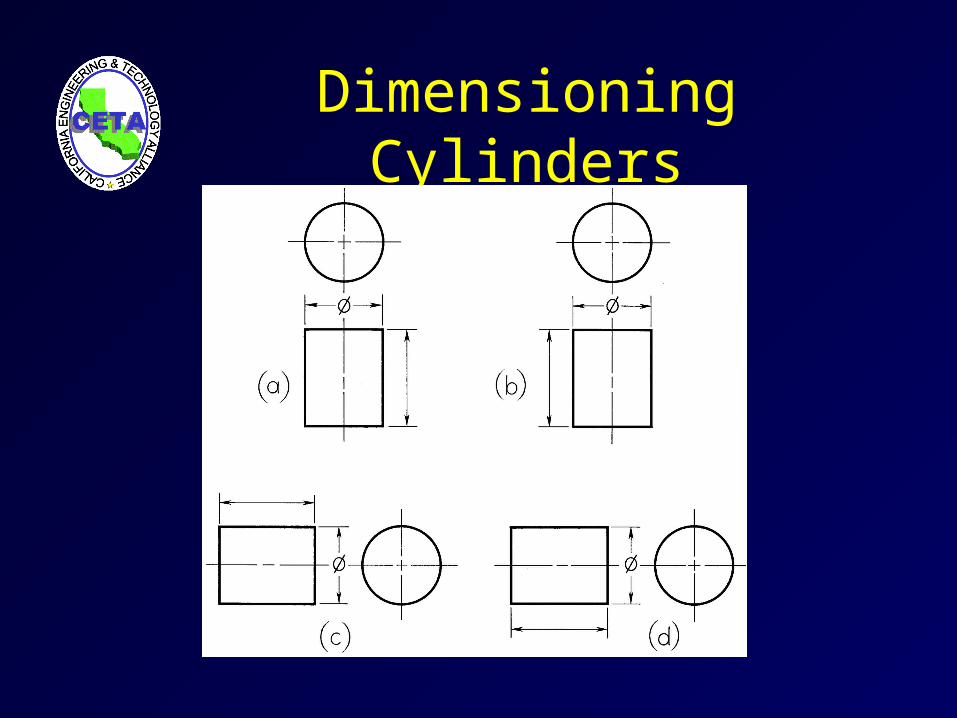
Dimensioning Cylinders
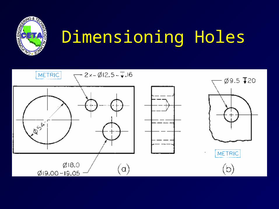
Dimensioning Holes
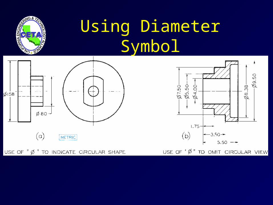
Using Diameter Symbol

Locating Holes

Coordinate Dimensioning

Summary• Good dimensioning is a combination of choosing
dimensions which reflect your design intent, proper technique in creating the details of the dimension line, extension line, arrowheads and dimension values, and placing the dimensions on the drawing so that they can be read clearly.
• Dimensioning drawings correctly can be as important or more important than drawing the shapes correctly.
• Good dimensioning requires practice and thought!

Where to get more information
• Refer to examples in your textbook• ASME, ANSI, ISO, and other organizations
publish standards.• Talk to people in manufacturing. Their experience
is valuable in helping you keep the cost of the product down by specifying reasonable tolerances and up-to-date manufacturing processes.


