Page 1
Diode Pumped Cryogenic High EnergyYb-Doped Ceramic YAG Amplifier forUltra-High Intensity Applications
P. D. Mason, S. Banerjee, K. Ertel, P. J. Phillips, C.Hernandez-Gomez, J. Collier
ICUIL 2010 ConferenceSeptember 26th to October 1st 2010, Watkins Glen, NY, USA
[email protected] 2.62 Central Laser FacilitySTFC, Rutherford Appleton Laboratory, OX11 0QX, UK+44 (0)1235 778301
Page 2
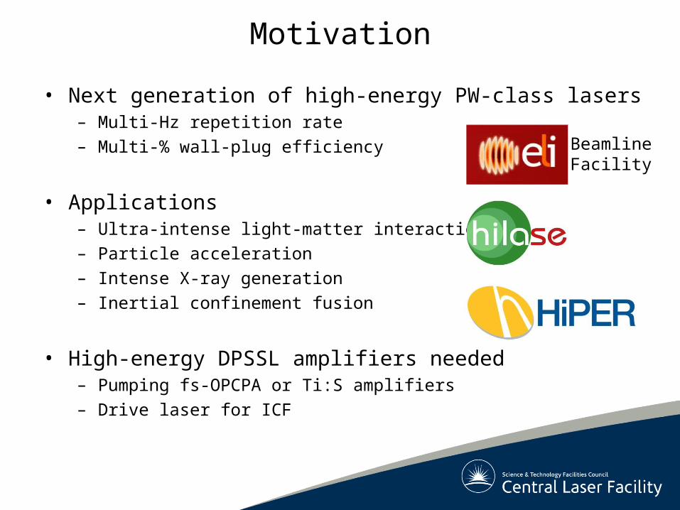
Motivation
• Next generation of high-energy PW-class lasers– Multi-Hz repetition rate
– Multi-% wall-plug efficiency
• Applications– Ultra-intense light-matter interactions
– Particle acceleration
– Intense X-ray generation
– Inertial confinement fusion
• High-energy DPSSL amplifiers needed– Pumping fs-OPCPA or Ti:S amplifiers
– Drive laser for ICF
BeamlineFacility
Page 3
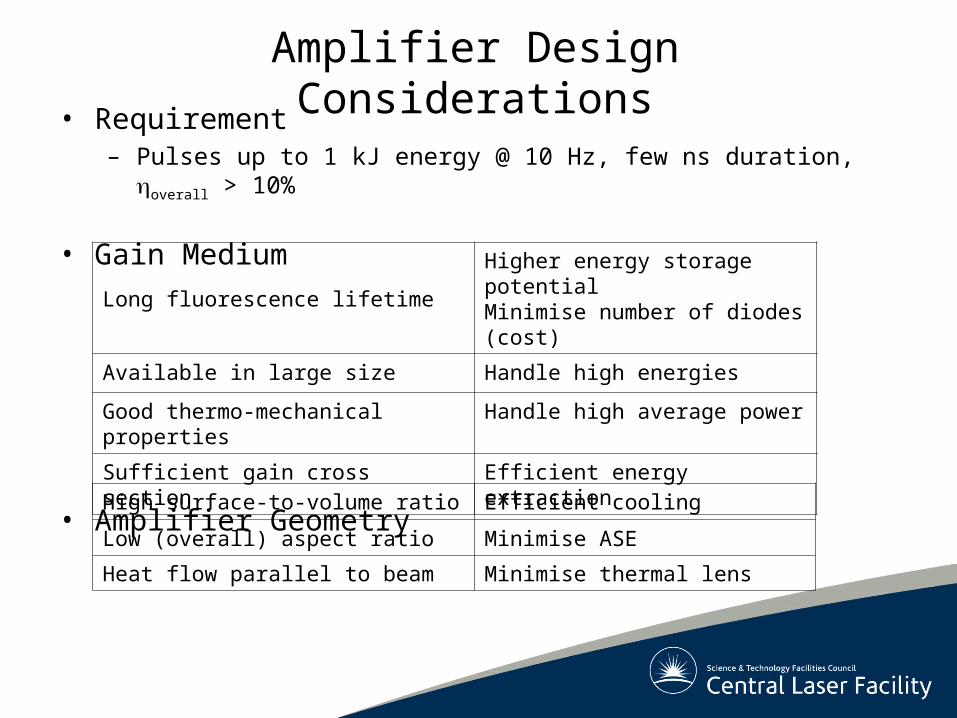
Amplifier Design Considerations
• Requirement– Pulses up to 1 kJ energy @ 10 Hz, few ns duration, overall > 10%
• Gain Medium
• Amplifier Geometry
Long fluorescence lifetimeHigher energy storage potentialMinimise number of diodes (cost)
Available in large size Handle high energies
Good thermo-mechanical properties Handle high average power
Sufficient gain cross section Efficient energy extraction
High surface-to-volume ratio Efficient cooling
Low (overall) aspect ratio Minimise ASE
Heat flow parallel to beam Minimise thermal lens
Page 4
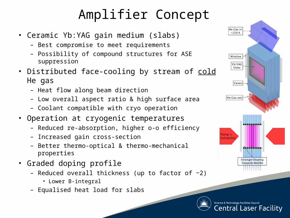
Amplifier Concept
• Ceramic Yb:YAG gain medium (slabs)– Best compromise to meet requirements
– Possibility of compound structures for ASE suppression
• Distributed face-cooling by stream of cold He gas – Heat flow along beam direction
– Low overall aspect ratio & high surface area
– Coolant compatible with cryo operation
• Operation at cryogenic temperatures– Reduced re-absorption, higher o-o efficiency
– Increased gain cross-section
– Better thermo-optical & thermo-mechanical properties
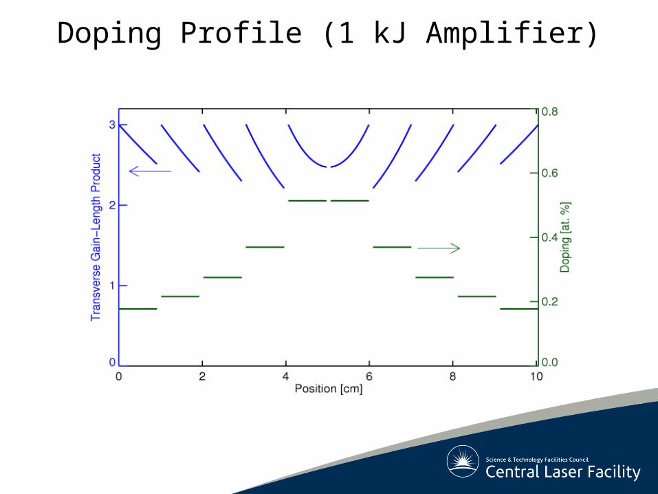
• Graded doping profile– Reduced overall thickness (up to factor of ~2)
• Lower B-integral
– Equalised heat load for slabs
Page 5
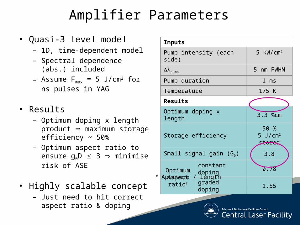
Inputs
Pump intensity (each side) 5 kW/cm2
pump 5 nm FWHM
Pump duration 1 ms
Temperature 175 K
Results
Optimum doping x length 3.3 %cm
Storage efficiency50 %
5 J/cm2 stored
Small signal gain (G0) 3.8
Optimum Aspect ratio#
constant doping 0.78
graded doping 1.55
Amplifier Parameters
• Quasi-3 level model– 1D, time-dependent model
– Spectral dependence (abs.) included
– Assume Fmax = 5 J/cm2 forns pulses in YAG
• Results– Optimum doping x length
product maximum storage efficiency ~ 50%
– Optimum aspect ratio to ensure g0D 3 minimise risk of ASE
• Highly scalable concept– Just need to hit correct aspect
ratio & doping
Inputs
Pump intensity (each side) 5 kW/cm2
pump 5 nm FWHM
Pump duration 1 ms
Temperature 175 K
# Aperture / length
Page 6
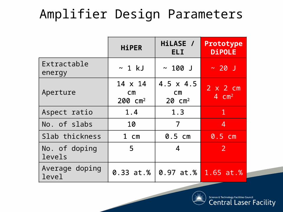
HiPERHiLASE /
ELIPrototypeDiPOLE
Extractable energy ~ 1 kJ ~ 100 J ~ 20 J
Aperture14 x 14 cm
200 cm2
4.5 x 4.5 cm20 cm2
2 x 2 cm4 cm2
Aspect ratio 1.4 1.3 1
No. of slabs 10 7 4
Slab thickness 1 cm 0.5 cm 0.5 cm
No. of doping levels 5 4 2
Average doping level
0.33 at.% 0.97 at.% 1.65 at.%
Amplifier Design Parameters
HiPERHiLASE /
ELI
Extractable energy ~ 1 kJ ~ 100 J
Aperture14 x 14 cm
200 cm2
4.5 x 4.5 cm20 cm2
Aspect ratio 1.4 1.3
No. of slabs 10 7
Slab thickness 1 cm 0.5 cm
No. of doping levels 5 4
Average doping level
0.33 at.% 0.97 at.%
Page 7
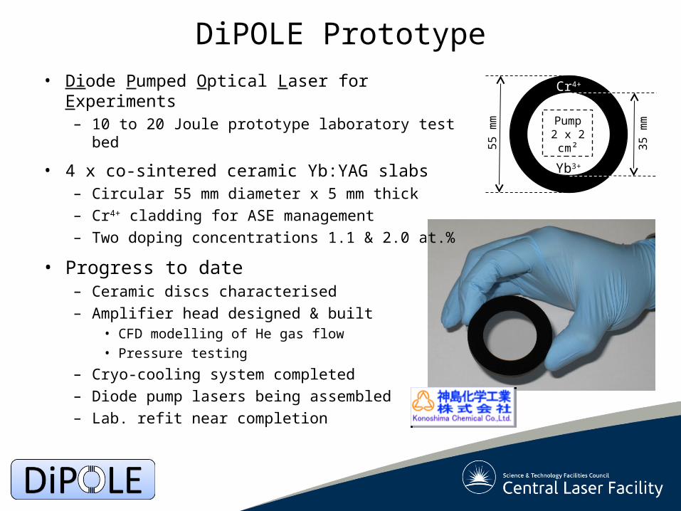
DiPOLE Prototype
Cr4+
Yb3+
35
mm
55
mm Pump
2 x 2cm²
• Diode Pumped Optical Laser for Experiments– 10 to 20 Joule prototype laboratory test bed
• 4 x co-sintered ceramic Yb:YAG slabs– Circular 55 mm diameter x 5 mm thick
– Cr4+ cladding for ASE management
– Two doping concentrations 1.1 & 2.0 at.%
• Progress to date– Ceramic discs characterised
– Amplifier head designed & built• CFD modelling of He gas flow• Pressure testing
– Cryo-cooling system completed
– Diode pump lasers being assembled
– Lab. refit near completion
Page 8
Ceramic Yb:YAG Discs
• Transmission spectra• Uncoated, room temperature
Fresnel limit ~84%
94
0 n
m 10
30
nm
• Transmitted wavefront
PV0.123wave
Page 9
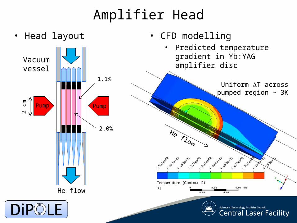
• Head layout
Amplifier Head
• CFD modelling• Predicted temperature gradient in
Yb:YAG amplifier disc
He flow
2 cm
2.0%
1.1%
PumpPump
Vacuumvessel
Uniform T across pumped region ~ 3K
He flow
Page 10
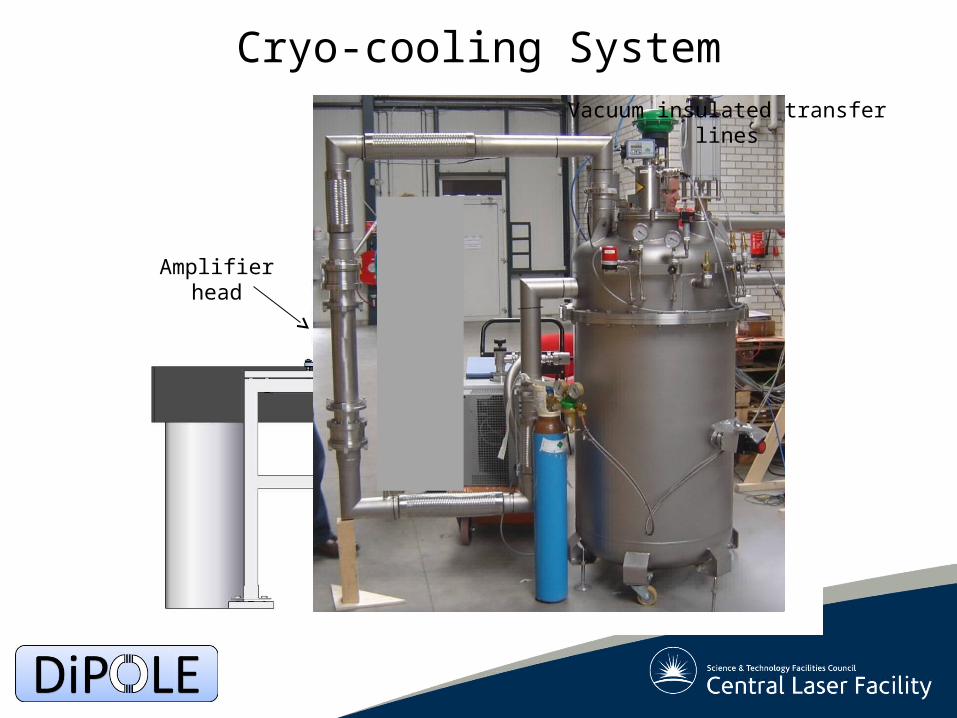
Cryostat
Amplifierhead
Helium cooling circuit
Cryo-cooling SystemVacuum insulated transfer
lines
Page 11
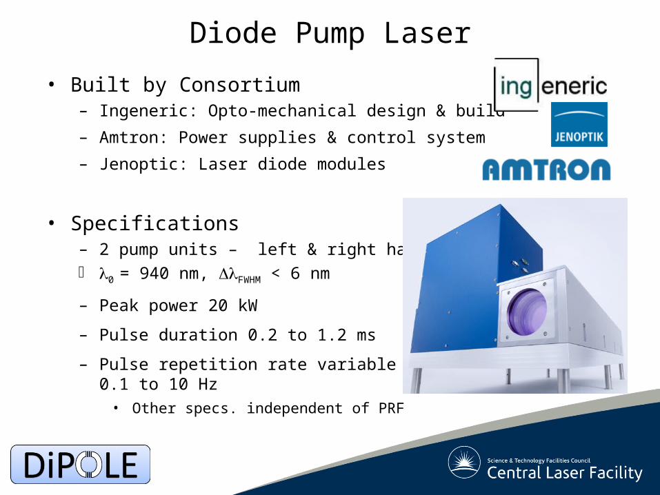
Diode Pump Laser
• Built by Consortium– Ingeneric: Opto-mechanical design & build
– Amtron: Power supplies & control system
– Jenoptic: Laser diode modules
• Specifications– 2 pump units – left & right handed 0 = 940 nm, FWHM < 6 nm
– Peak power 20 kW
– Pulse duration 0.2 to 1.2 ms
– Pulse repetition rate variable 0.1 to 10 Hz
• Other specs. independent of PRF
Page 12
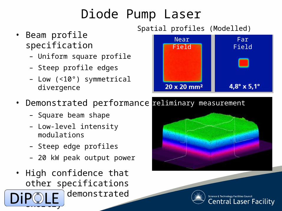
Diode Pump Laser
• Beam profile specification– Uniform square profile
– Steep profile edges
– Low (<10°) symmetrical divergence
• Demonstrated performance– Square beam shape
– Low-level intensity modulations
– Steep edge profiles
– 20 kW peak output power
• High confidence that other specifications will be demonstrated shortly
Spatial profiles (Modelled)
Near Field Far Field
Preliminary measurement
Page 13
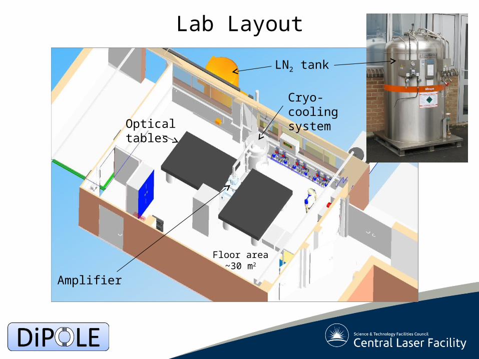
Lab Layout
Optical tables
Amplifier
LN2 tank
Floor area ~30 m2
Cryo-coolingsystem
Page 14
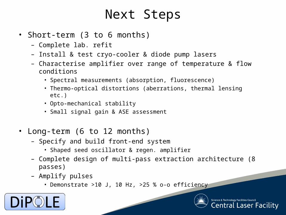
Next Steps
• Short-term (3 to 6 months)– Complete lab. refit
– Install & test cryo-cooler & diode pump lasers
– Characterise amplifier over range of temperature & flow conditions• Spectral measurements (absorption, fluorescence)• Thermo-optical distortions (aberrations, thermal lensing etc.)• Opto-mechanical stability• Small signal gain & ASE assessment
• Long-term (6 to 12 months)– Specify and build front-end system
• Shaped seed oscillator & regen. amplifier
– Complete design of multi-pass extraction architecture (8 passes)
– Amplify pulses• Demonstrate >10 J, 10 Hz, >25 % o-o efficiency
Page 16
Yb-doped Materials
Parameter (at RT) Glass S-FAP YAG CaF2
Wavelengths(pump/emission in nm)
940-980 / 1030
900 /1047
940 /1030
940-980 / 1030
Fluorescence lifetime(msec)
~ 2.0 ~ 1.3 ~ 1.0 ~ 2.4
Emission cross-section(peak x10-20 cm2)
0.7 6.2 3.3 0.5
Gain Low High Medium Low
Non-linear index(n2 x 10-13 esu)
0.1 to1.2
1.5 2.7 0.43
BandwidthHigh
> 50 nmLow OK?
High> 50 nm
Availability of large aperture
Good LimitedOK
(Ceramic)Limited
(Ceramic)
Thermal properties(K in Wm-1K-1)
Poor1.0
OK2.0
Good10.5
OK6.1
Page 17
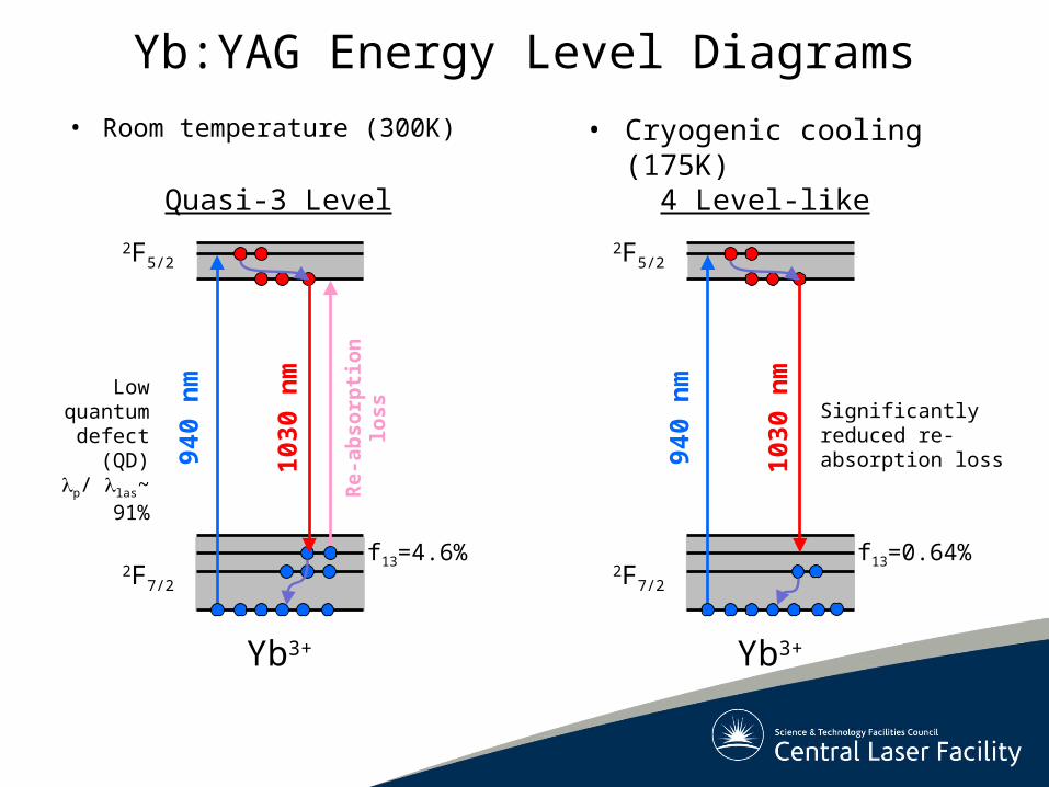
Yb:YAG Energy Level Diagrams
• Room temperature (300K)
940
nm
Yb3+
2F7/2
1030
nm
Quasi-3 Level
2F5/2
Re-
abso
rpti
on
loss
Low quantum defect (QD)
p/ las~ 91%
f13=4.6%
• Cryogenic cooling (175K)
940
nm
Yb3+
2F7/2
1030
nm
4 Level-like
2F5/2
Significantly reduced re-absorption loss
f13=0.64%
Page 18
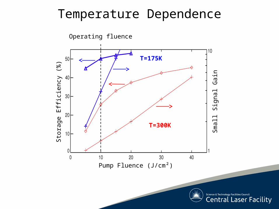
Temperature Dependence
Pump Fluence (J/cm²)
Sto
rage
Effi
cien
cy (
%)
Sm
all S
igna
l Gai
n
T=175K
T=300K
Operating fluence
Page 19
Doping Profile (1 kJ Amplifier)
Page 20
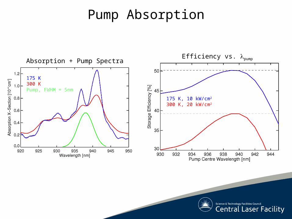
Absorption + Pump Spectra
175 K300 KPump, FWHM = 5nm
175 K, 10 kW/cm2
300 K, 20 kW/cm2
Efficiency vs. pump
Pump Absorption
Page 21
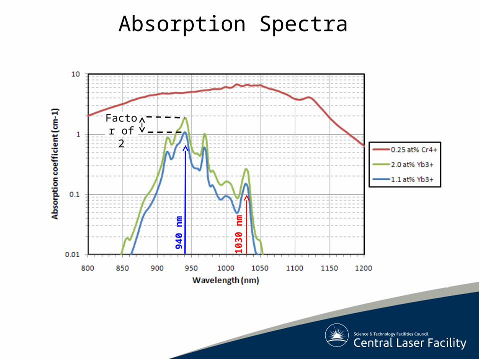
Absorption Spectra
940
nm
103
0 n
m
Factor of 2
Page 22
Ceramic YAG with Absorber Cladding
Cr4+:YAG
Yb:YAG
LaserCamera
?
Cr4+:YAG
Yb:YAG
Sample of Co-Sintered YAG(Konoshima)
Reflection at Interface?
a cb
a b c
Nothing!
Page 23
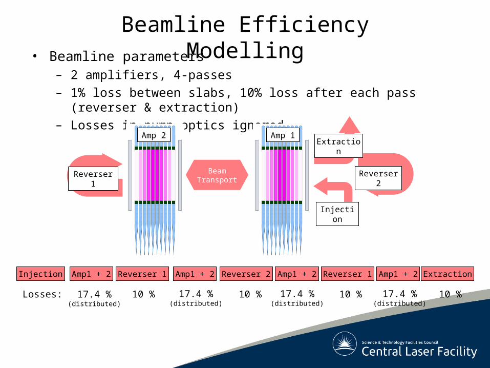
Beamline Efficiency Modelling• Beamline parameters
– 2 amplifiers, 4-passes
– 1% loss between slabs, 10% loss after each pass (reverser & extraction)
– Losses in pump optics ignored
Beam Transport
Reverser 1 Reverser 2
Injection
ExtractionAmp 1Amp 2
Injection Amp1 + 2 Reverser 1 Amp1 + 2 Reverser 2 Amp1 + 2Reverser 1 ExtractionAmp1 + 2
Losses: 17.4 %(distributed)
10 % 10 %10 % 10 %17.4 %(distributed)
17.4 %(distributed)
17.4 %(distributed)