1 IPTV AND VOD NETWORK ARCHITECTURES Diogo Miguel Mateus Farinha Instituto Superior Técnico Av. Rovisco Pais, 1049-001 Lisboa, Portugal E-mail: [email protected]ABSTRACT IPTV and Video on Demand are, nowadays, two promissory services, capable of helping operators to support the loss of profit in fix phone market. The major problem of the Video on Demand is how it can be delivered to clients. A real Video on Demand system, where each client can watch the video he wants and whenever he wants, requires huge bandwidth resources. At this context, operators try to develop some solutions to make their networks more scalable. This work proposes a new architecture to organize video servers in the network, based on peer-to-peer models. This architecture will be tested in a network simulator, as well as the operator’s solution. Tests done in this work demonstrate that P2P distributed architecture can reduce the utilization of bandwidth in the IP/MPLS core, keeping or reducing time needed to satisfy requests. Key-words: IPTV, Video on Demand, architectures of networks, peer-to-peer, simulation 1. INTRODUCTION Although the video digitalization isn’t recent, the existent networks weren’t reliable to support this kind of services. With the great advances in technology, concerning the video codification and access networks, these services become attractive to operators and clients. Services like IPTV and VoD require huge amounts of bandwidth to operators network. Nowadays, operators are evolving their network to a new generation network using access technologies like Fiber-To-The-Home/Building/Curb (FTTx). But current network need to be adapted to assure that these services can be delivery now. There are several architectures to accomplish this goal. In this work there will be analyzed 2 types, centralized and distributed based on P2P topologies. The operator, whose network serves as a base to this work, adopted a centralized solution. In this work it will be proposed and simulated a distributed alternative 2. STATE OF ART In this chapter it will be presented the results of the survey made in terms of networks architectures for providing the services referred. This survey was made in terms of centralized and distributed architectures. 2.1. Centralized Solutions In terms of centralized solutions, this paper will present two different solutions. The first is Content Distribution Network (CDN) and the second is Multicast. 2.1.1 Content Distribution Network CDN are used since several years in Internet for content distribution, to reduce the time for content acquisition from clients [1]. To do this some strategically edge servers are placed in the network and clients get their contents from these instead from central server. There are some central servers somewhere in the network where in first time contents are placed. Then these contents are replicated to distributed servers according to some policies. Client’s requests are then forwarded to these edge servers where the contents they want are allocated. 2.1.2 Multicasting Multicast is the major technique for IPTV delivery. It can deliver efficiently in the network some data streaming from a sender to multiple receivers. There are some different approaches in multicast [2], one-to-all unicast, Application- level multicast and explicit multicast. 2.2 Distributed Solutions Centralized solutions present some limitations, in terms of scalability, especially in operator’s networks where bandwidth is an extremely value resource. In order to improve bandwidth usage it can be used a peer-to-peer network topology. A peer-to-peer network is a distributed network that combines a group of distributed, heterogenic
Transcript
1
IPTV AND VOD NETWORK ARCHITECTURES
Diogo Miguel Mateus Farinha
Instituto Superior Técnico Av. Rovisco Pais, 1049-001 Lisboa, Portugal
IPTV and Video on Demand are, nowadays, two promissory services, capable of helping operators to support the loss of profit in fix phone market.
The major problem of the Video on Demand is how it can be delivered to clients. A real Video on Demand system, where each client can watch the video he wants and whenever he wants, requires huge bandwidth resources. At this context, operators try to develop some solutions to make their networks more scalable. This work proposes a new architecture to organize video servers in the network, based on peer-to-peer models. This architecture will be tested in a network simulator, as well as the operator’s solution. Tests done in this work demonstrate that P2P distributed architecture can reduce the utilization of bandwidth in the IP/MPLS core, keeping or reducing time needed to satisfy requests. Key-words: IPTV, Video on Demand, architectures of networks, peer-to-peer, simulation
1. INTRODUCTION
Although the video digitalization isn’t recent, the existent networks weren’t reliable to support this kind of services. With the great advances in technology, concerning the video codification and access networks, these services become attractive to operators and clients.
Services like IPTV and VoD require huge amounts of bandwidth to operators network. Nowadays, operators are evolving their network to a new generation network using access technologies like Fiber-To-The-Home/Building/Curb (FTTx). But current network need to be adapted to assure that these services can be delivery now. There are several architectures to accomplish this goal. In this work there will be analyzed 2 types, centralized and distributed based on P2P topologies. The operator, whose network serves as a base to this work, adopted a centralized solution. In this work it will be proposed and simulated a distributed alternative
2. STATE OF ART
In this chapter it will be presented the results of the survey made in terms of networks architectures for providing the services referred. This survey was made in terms of centralized and distributed architectures.
2.1. Centralized Solutions
In terms of centralized solutions, this paper will present two different solutions. The first is Content Distribution Network (CDN) and the second is Multicast. 2.1.1 Content Distribution Network CDN are used since several years in Internet for content distribution, to reduce the time for content acquisition from clients [1]. To do this some strategically edge servers are placed in the network and clients get their contents from these instead from central server.
There are some central servers somewhere in the network where in first time contents are placed. Then these contents are replicated to distributed servers according to some policies. Client’s requests are then forwarded to these edge servers where the contents they want are allocated. 2.1.2 Multicasting Multicast is the major technique for IPTV delivery. It can deliver efficiently in the network some data streaming from a sender to multiple receivers. There are some different approaches in multicast [2], one-to-all unicast, Application-level multicast and explicit multicast.
2.2 Distributed Solutions
Centralized solutions present some limitations, in terms of scalability, especially in operator’s networks where bandwidth is an extremely value resource. In order to improve bandwidth usage it can be used a peer-to-peer network topology. A peer-to-peer network is a distributed network that combines a group of distributed, heterogenic
2
and independent peers who share between then resources like storage capability or objects [3]. 2.2.1 Plaxton In a Plaxtron [4] network, videos and servers have identifiers independents of their location and semantic properties. These identifiers are random and have a dimension of 160 bits. It is assumed in this topology that identifiers are uniformly distributed thru the servers and videos identifiers space. Each server has a neighborhood table where it has the IDs of the closest servers. There is another table in each server where are identified the known servers and theirs videos. In terms of organization the videos are organized in trees. When a server S wants to publish a video O, this server sends a message to the root server of video O. During the path to the root server all servers where the message pass update their tables with the information that the video O is in the server S. When a server is looking for a video it sends a message to the root of that video, but if that message passes in a server where the information is already available the request is satisfied. 2.2.2 Tapestry Tapestry [5][6], is a self-organized and scalable topology to object location and request routing. This topology allows routing a request to the nearest copy of a given object, balancing at same time requests. The routing mechanisms of Tapestry are based on Plaxton, disposing of some other to improve scalability and availability and fail resistance. Like in Plaxton , each server in tapestry has a table with his neighbors. The difference is that beside this each server has a reference to all servers that reference him as a neighbor. The videos in this topology are organized as trees, but there is a great diference to Plaxton. In Plaxton a video can only have a root for his tree, and in Tapestry it can have several. The location mechanism is similar to the one in Plaxton. There is a diference in terms of video location. In both topologies we can have multiple copies of a video in the network, but in Plaxton a server has only the location of the closest video in the network, while tapestry stores all locations of the video. Not always the closest copy of the video is the best to get, for example the server that has it can be overloaded with requests, so its better to get a copy of the video that is in a far but free server. 2.2.3 Pastry In a Pastry network [7], each server has an identifiers with 128 bits created randomly and distributed uniformly in the server’s identifier space. Once again like in some other topologies it uses a hash function on server IP or public key. Each server has a routing table with the others server in the network’s IP. This routing table organizes the servers in
layers. In the layer n are the servers, which share n bits in the identifiers with the server who own the table, and so on. In this topology all the videos have and identifiers just like the servers. When a request for a video V is made, it is sent to the server which identifiers is closer to V. 2.2.4 Chord In Chord [8], each server has an identifier that results from the application of a hash function to his IP. Videos have and identifier too resulting from the application of a hash function to it’s key. It is pretended to distribute uniformly the identifiers of the videos and server thru the identifiers space. Server’s identifiers are ordered increasingly and placed in a ring. Videos are then placed in the server whose ID is equal or immediately higher then his ID. Each server has a routing table with the information of the next server in the ring. This means that each server has only a part of the routing information and don’t know all network. When a server receives a request for a video it looks in his routing table for the next server in the ring and re-sends the request to him until it reaches his destination. The video requested is then sent back thru this route. 2.2.5 Content Addressable Network Content Addressable Network (CAN) [9] is a distributed peer-to-peer topology organized in a multidimensional cartesian space. This space is divided between all servers. Each of these servers is represented by his IP address, and has a routing table with all his neighbors and their location on the cartesian space. All keys of videos in this topology are mapped in the cartesian space using an hash function. When a server wants to locate a video, it uses this hash function in that video key. Then searches in his routing table for which neighbor he should send the message. The neighbor who receives the messages does exactly the same thing until the message reaches its destination. 2.2.6 Kademlia Kademlia [10] topology follows the same approach as previous topologies concerning the attribution of identifiers. Each server and video in the network has an identifier. Videos are stored in the server who has the closest identifiers. To locate the server, it is used a metric based on XOR between servers IDs. Each server has a list with the servers that have a determined distance from him. These lists are identified as k-buckets and are used to route the request to its destination.
3
2.2.7 Viceroy Viceroy [11] is decentralized peer-to-peer topology used to find and locate objects. It uses consistent hash functions [29] to distribute videos for a group of servers uniformly. Like is chord, servers are aligned in a ring ordered by their identifiers. Videos have keys too, and each of these videos is stored in the server that has the same or immediately higher identifier. The difference to Chord is those servers are in more then one ring. This allows a server to send a message not only to the next server but also to a distance server that is in another ring. These rings are known as levels. 2.2.8 Distributed Models Comparison and Evaluation Is the section it will be done a summary comparison between all models referred above.
The location and routing system presented by Plaxton topology has several advantages, but also some disadvantages [6]. It can handle fails either from connections or from servers, since the routing mechanism only needs that the next server shares a few bits with this server. In case a server or connection is down the topology can use another way out. All routing is based on information present locally on the server. This can be good but when there is a great amount of routing information on servers, managing these can be inefficient and difficult. The distance that a message travels is proportional to the physical distance of the network in this topology. In other hand since the routing is done based on information on each server it means, as referred before, that each server must have all topology of network represented in his routing tables. Since there is no update algorithm this topology doesn’t allow new nodes to join the network. This problem also means that some other information about the network like temporally congestion points can’t be used to help routing.
Tapestry and Pastry topologies are based in the Plaxton topology, principally in the routing mechanism. Therefore they share the same advantages adding some features to solve Plaxton problems. Both these topologies allow new servers to join the network and some others to leave, increasing this way the system scalability, availability and resilience to faults. Beside this, there are some differences between both approaches. They use the locality concept in the network. Logical path that a message travels is proportional to the physical one. But the way they use to arrive this concept is different, and it is less complex in Pastry [7].
In Chord, the main difference to topologies like Tapestry and Pastry consists in the way that the logical network topology is related to the physical. In a Chord topology there isn’t a concept like network locality. Because servers have and identifiers created using and hash function and then are mapped in a ring, this means that close servers in a ring can be distant in the reality. Another advantage is that
each server has only a part of the routing information, and doesn’t need to know the entire network. This means that the routing system is less complex, and so Chord is probably the simplest topology to implement [8].
In a CAN topology the routing is done only to neighbors servers. This means that each server only has to now few other servers in the network. For large networks this mean that the routing tables in CAN are much less heavier then the ones in a topology like Tapestry or Pastry.
Kademlia gets his advantages from the use of the metric XOR to determine the distance between servers [10]. This metric is simetric, so when a server receives a request he can use the information in this request to determine the distance to the server that sent the message. This way, servers get information from network topology quickly then in other solutions.
Viceroy approach is influenced by Chord. Both use identifiers for servers, and then place then in a ring to route the messages. The big difference is that Viceroy has more then one ring, or level, and so can route messages quickly then Chord.
3. SYSTEM ARCHITECTURE
In this section of the paper it will be detailed all the developing process of system architecture. In the previous sections were isolated two families of solutions, centralized and distributed based on peer-to-peer models. It will be based on these that the following work will be centered, especially with the proposed architecture based on the distributed models discussed above.
3.1 Goals and Requirements
The goal of this work is to propose an alternative architecture to deliver video services. Looking for the solutions detected in the survey, and analyzing the services, IPTV and VoD, it can be concluded that the Multicast is a good option to use to deliver IPTV. It is efficient for delivering a stream of data from a sender to multiple receivers and that is basically the objective of this service. In other hand there is the VoD service. This service has a different nature from IPTV. It is a unicast service, meaning that it will have a different stream for each client. So it is much more exigent in terms of resources from the network. Taking this into count, from now on this work will focus on proposing and distributed architecture for the VoD service.
In terms of requirements, it is important to have a network prototype as close as possible to network operators. This will help to get results as close as the ones got in a real network.
4
3.2 Operator’s Network
The network from a telecommunication operator presents topically and hierarchic topology. It is divided in levels, Core, Service Routing 1 and Service Routing 2. To deliver a service like VoD, operator uses some video servers organized in clusters. Each cluster must have enough servers so that in case of fail in some the other can handle the service. In figure 3.1 there is a generic scheme of architecture from a telecommunication operator.
Figure 3-1 Generic architecture from a telecommunication operator to deliver VoD service.
Looking to figure 3.1, it is possible to see that in a earlier phase the VoD service will be delivered from the core level to all clients. This has some advantages as:
• Low costs of Operation and Maintenance; • Easy to implement and capable of supporting and
early phase of the service;
But as some disadvantages as: • Extremely high costs to scale; • Requires extremely high resources to core network,
like bandwidth; • Excessively centralized;
The problem is that when the number of clients increases
greatly this solution wont be efficient. So the operator will distribute the video server thru the Service Routing 1 (SR1) level, figure 3-2.
Figure 3-2 Architecture after first decentralization phase
This decentralization minimizes the resources required from core level and is more scalable, but has bigger Operation and Maintenance costs. The problem once again is when the number of clients increases as before. When it happens, this solution will suffer from same problems as previous. So operator proceeds to another decentralization, this time placing video servers in SR2, figure 3-3.
Figure 3-3 Last decentralization phase with installation of server in SR2 level.
This is the last decentralization phase possible for now cause SR2 is the last routing level, and after this level there is only DSLAMs which don’t work on IP level for now, on this operator network, and the client house. But for legal reasons it isn’t possible to store videos on client’s house.
3.3 Network Architectures
Considering the evolution strategy of the operator, it will be proposed in this work a different architecture for the video servers placed on SR2 level. This is because the operator already has servers installed in level SR1, so these must be re-used to reduce the investment. This architecture will be simulated and compared with the one adopted by the operator for SR2 level.
IP/MPLS
10 GbE
!"#$%&'$()$(&10 GbE
1 GbE
1 GbE
1 GbE
*+,-+.-&
'/0&12/+&
.2/3+&
2X1GbE
2X1GbE
'/4&
10 GbE
10 GbE
!"#$%&'$()$(&
5"67%8&
9(78:8&
;%:8&
1$:<(%&
;%:8&'=>&
IP/MPLS
10 GbE
!"#$%&'$()$(&10 GbE
1 GbE
1 GbE
1 GbE
*+,-+.-&
'/0&12/+&
.2/3+&
2X1GbE
2X1GbE
'/4&
10 GbE
10 GbE
!"#$%&'$()$(&
5"67%8&
9(78:8&
;%:8&
1$:<(%&
;%:8&'=>&
REGIONAL CENTER
D-SERVERS
V-SERVERS
IP/MPLS
10 GbE
!"#$%&'$()$(&10 GbE
1 GbE
1 GbE
1 GbE
*+,-+.-&
'/0&12/+&
.2/3+&
2X1GbE
2X1GbE
'/4&
10 GbE
10 GbE
!"#$%&'$()$(&
5"67%8&
9(78:8&
;%:8&
1$:<(%&
;%:8&'=>&
REGIONAL CENTER
D-SERVERS
V-SERVERS
D-SERVERS
V-SERVERS
REGIONAL CENTER
5
3.3.1 Centralized
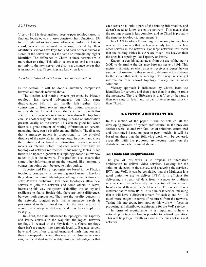
The architecture for video server on SR2 level adopted by the operator is a centralized architecture. Since there are already servers installed on SR1 level these will work as server and the one in SR2 level will work as clients to these, figure 3-4.
Figure 3-4 Scheme of centralized architecture in SR1 and SR2 level In each SR2 router is installed a cluster of servers. These servers are responsible to satisfy all clients from the zone served by that router. When a cluster hasn’t the video requested, it does a request to the SR1 cluster for that video. If this SR1 server doesn’t have that video, the request will have to travel to the core. 3.3.2 Distributed
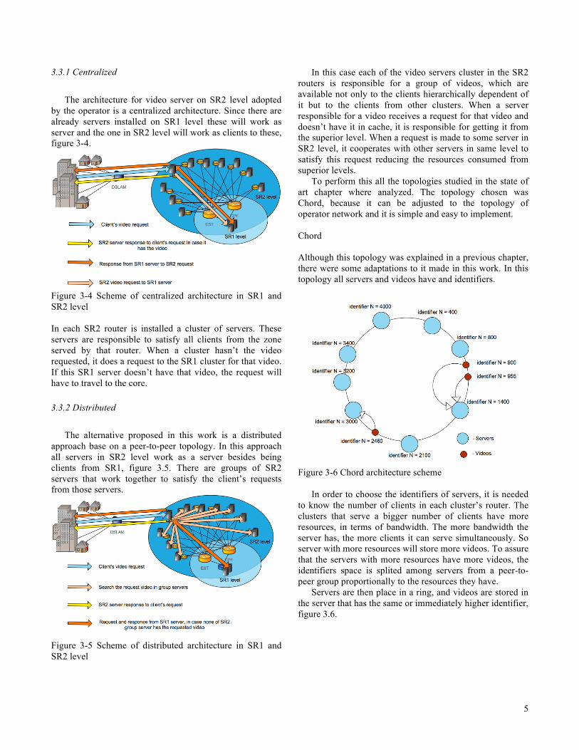
The alternative proposed in this work is a distributed approach base on a peer-to-peer topology. In this approach all servers in SR2 level work as a server besides being clients from SR1, figure 3.5. There are groups of SR2 servers that work together to satisfy the client’s requests from those servers.
Figure 3-5 Scheme of distributed architecture in SR1 and SR2 level
In this case each of the video servers cluster in the SR2 routers is responsible for a group of videos, which are available not only to the clients hierarchically dependent of it but to the clients from other clusters. When a server responsible for a video receives a request for that video and doesn’t have it in cache, it is responsible for getting it from the superior level. When a request is made to some server in SR2 level, it cooperates with other servers in same level to satisfy this request reducing the resources consumed from superior levels.
To perform this all the topologies studied in the state of art chapter where analyzed. The topology chosen was Chord, because it can be adjusted to the topology of operator network and it is simple and easy to implement.
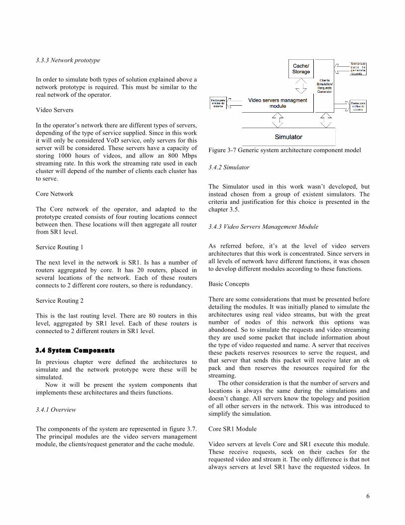
Chord Although this topology was explained in a previous chapter, there were some adaptations to it made in this work. In this topology all servers and videos have and identifiers.
Figure 3-6 Chord architecture scheme
In order to choose the identifiers of servers, it is needed to know the number of clients in each cluster’s router. The clusters that serve a bigger number of clients have more resources, in terms of bandwidth. The more bandwidth the server has, the more clients it can serve simultaneously. So server with more resources will store more videos. To assure that the servers with more resources have more videos, the identifiers space is splited among servers from a peer-to-peer group proportionally to the resources they have.
Servers are then place in a ring, and videos are stored in the server that has the same or immediately higher identifier, figure 3.6.
6
3.3.3 Network prototype In order to simulate both types of solution explained above a network prototype is required. This must be similar to the real network of the operator. Video Servers In the operator’s network there are different types of servers, depending of the type of service supplied. Since in this work it will only be considered VoD service, only servers for this server will be considered. These servers have a capacity of storing 1000 hours of videos, and allow an 800 Mbps streaming rate. In this work the streaming rate used in each cluster will depend of the number of clients each cluster has to serve. Core Network The Core network of the operator, and adapted to the prototype created consists of four routing locations connect between then. These locations will then aggregate all router from SR1 level. Service Routing 1 The next level in the network is SR1. Is has a number of routers aggregated by core. It has 20 routers, placed in several locations of the network. Each of these routers connects to 2 different core routers, so there is redundancy. Service Routing 2 This is the last routing level. There are 80 routers in this level, aggregated by SR1 level. Each of these routers is connected to 2 different routers in SR1 level.
3.4 System Components
In previous chapter were defined the architectures to simulate and the network prototype were these will be simulated.
Now it will be present the system components that implements these architectures and theirs functions.
3.4.1 Overview The components of the system are represented in figure 3.7. The principal modules are the video servers management module, the clients/request generator and the cache module.
Figure 3-7 Generic system architecture component model 3.4.2 Simulator The Simulator used in this work wasn’t developed, but instead chosen from a group of existent simulators. The criteria and justification for this choice is presented in the chapter 3.5. 3.4.3 Video Servers Management Module As referred before, it’s at the level of video servers architectures that this work is concentrated. Since servers in all levels of network have different functions, it was chosen to develop different modules according to these functions. Basic Concepts There are some considerations that must be presented before detailing the modules. It was initially planed to simulate the architectures using real video streams, but with the great number of nodes of this network this options was abandoned. So to simulate the requests and video streaming they are used some packet that include information about the type of video requested and name. A server that receives these packets reserves resources to serve the request, and that server that sends this packet will receive later an ok pack and then reserves the resources required for the streaming.
The other consideration is that the number of servers and locations is always the same during the simulations and doesn’t change. All servers know the topology and position of all other servers in the network. This was introduced to simplify the simulation. Core SR1 Module Video servers at levels Core and SR1 execute this module. These receive requests, seek on their caches for the requested video and stream it. The only difference is that not always servers at level SR1 have the requested videos. In
7
other hand Core servers always have all contents so they only receive requests, while SR1 servers may perform some requests to Core. The use of this module is equal for centralized architecture in operator’s architecture and for the one distributed proposed in this work. This happens because as referred before, the architecture proposed is only for level SR2. Chord SR2 Module The topology chord was already detailed in this paper, so only implementations details will be referred. Servers in SR2 are combined in peer-to-peer groups, to serve client’s requests without sending requests to superior network levels. In this network prototype, a chord group is constituted by the clusters in SR2, which are aggregated by the same SR1 router. When a server S receives a request it checks if it is the responsible server for that video in the group. If it is and has the video in cache streams the video otherwise makes a request to the SR1 server for that video. If a serves S that receives a video request isn’t the responsible for it in the groups, it calculates who is this server R and re-sends the request to it. The server R is now responsible to stream the video to client.
It was developed a second version of this module. In this version when a server S receives a request for a video V that isn’t of his responsibility, it finds who is the server R responsible. Then this server R instead of streaming the video directly to client streams it to server S who stores it in cache, streaming it to the client simultaneously. This second version needs obviously more resources then the first one. SERVER SR2 Module The functions this module implements are similar to Core SR1 Module. It receives requests, from the module that simulates the clients, search in his cache for the video requested and streams it in case it is available. Otherwise send a request to the superior servers requesting it. 3.4.4 Cache/ Storage Module All video servers in all levels of the network have a cache model.
The model used in a centralized architecture is based in a popularity model. When a video is requested to a server S it checks its cache for that video. If it is there its popularity is increased and is streamed to the client. If not, server S re-sends the request to the hierarchically higher server H.
In a distributed architecture there are two version of cache model, one for each version considered in the Chord SR2 module. In the first version a client sends a request to the server S. If this server S is responsible for the video checks its cache and streams the video if available. If not, finds the responsible server R in the peer-to-peer group for that video and re-sends the request to it. These servers R
will response to client in behalf of server S. So in this version, video servers only store in cache the video that they are responsible for.
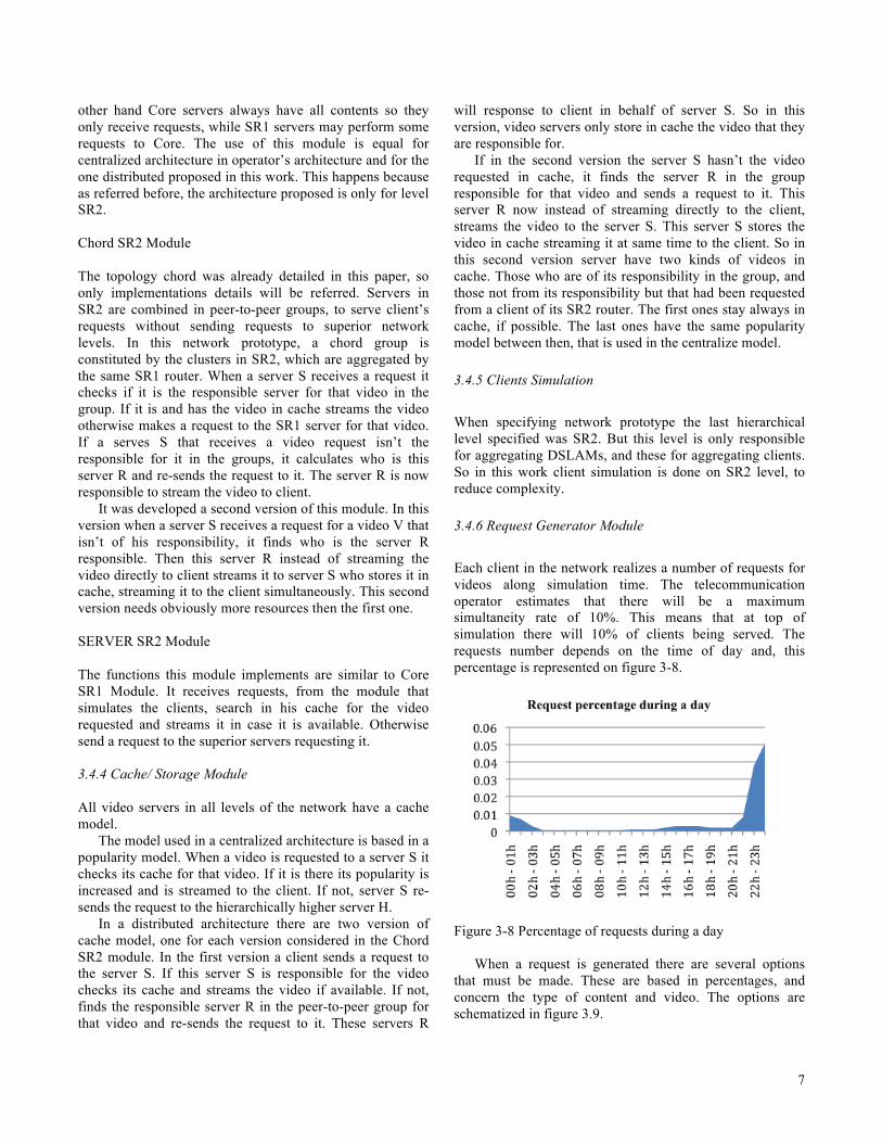
If in the second version the server S hasn’t the video requested in cache, it finds the server R in the group responsible for that video and sends a request to it. This server R now instead of streaming directly to the client, streams the video to the server S. This server S stores the video in cache streaming it at same time to the client. So in this second version server have two kinds of videos in cache. Those who are of its responsibility in the group, and those not from its responsibility but that had been requested from a client of its SR2 router. The first ones stay always in cache, if possible. The last ones have the same popularity model between then, that is used in the centralize model. 3.4.5 Clients Simulation When specifying network prototype the last hierarchical level specified was SR2. But this level is only responsible for aggregating DSLAMs, and these for aggregating clients. So in this work client simulation is done on SR2 level, to reduce complexity. 3.4.6 Request Generator Module Each client in the network realizes a number of requests for videos along simulation time. The telecommunication operator estimates that there will be a maximum simultaneity rate of 10%. This means that at top of simulation there will 10% of clients being served. The requests number depends on the time of day and, this percentage is represented on figure 3-8.
Figure 3-8 Percentage of requests during a day
When a request is generated there are several options that must be made. These are based in percentages, and concern the type of content and video. The options are schematized in figure 3.9.
8
Figure 3-9 Options this module has to do when generating a new content.
The time between consecutive request are simulate with base on Poisson model [12].
3.5 Simulator
In order to simulate architectures it was done a survey for existent network simulators. There were defined some criteria to select a group of simulators and then to chose the best among then. These criteria were:
• Support for adding extra modules that allow simulating the topologies and protocols required;
• Support the construction of hierarchical network topologies;
• Easiness to add and integrate extra modules; Based on these tree requirements there were chosen four simulators. OPNET [13]
This commercial simulator has a good interface and allows the construction of hierarchical networks. The problem with this server is that it’s hard to develop and integrate news modules in it, so after trying, it was discarded for this work. NS2 [14]
Network Simulator-2 is one of the must used network simulator in network investigation. The problem with this simulator is that it’s hard to construct the kind of networks requires and to integrate some extra modules developed externally. SSFNET [15]
This simulator can fulfill all the requirements referred before. It’s not complex to create the networks required and to add, and integrate some external modules.
J-Sim [16]
The last simulator analyzed is J-Sim. It is very similar to SSFNET so is a good option for this work. It allows to easily add the developed modules. In terms of network creation, it is even simpler then in SSFNET. For all these reason J-Sim was the chosen network simulator in this work.
3.6 Evaluation Metrics
To evaluate the results of the simulation some metrics must be defined to compare the architectures. There were defined tree types of metrics. The first one concerns the evaluation of video servers occupation. The second pretend to evaluate the occupation of the different network level, Core, SR1 and SR2. The third and last is a temporal metric that evaluates the time necessary to find a video in each of the architectures.
4. TESTS AND RESULTS
4.1 Test Scenarios
The tests were realized with a population of 600000 Clients and 5000 hours of contents, representing 2500 videos considering each video taking 2 hours. They were considered six solutions, with and without previous distribution of more popular contents: - Centralized architecture; (Centralized) - Distributed based on Chord, first version, where servers only store the videos that they are its responsibility; (Chord V1) - Distributed based on Chord, second version, where each serve stores not only the videos they are responsible for but the ones asked for clients they are responsible for; (Chord V2)
4.2 Results
Figure 4-1 Median server occupations of all servers during the 10 days simulation.
In terms of bandwidth occupation the results in the figure 4-2 show that centralized architecture without previous distribution of more popular contents is the worst solution.
9
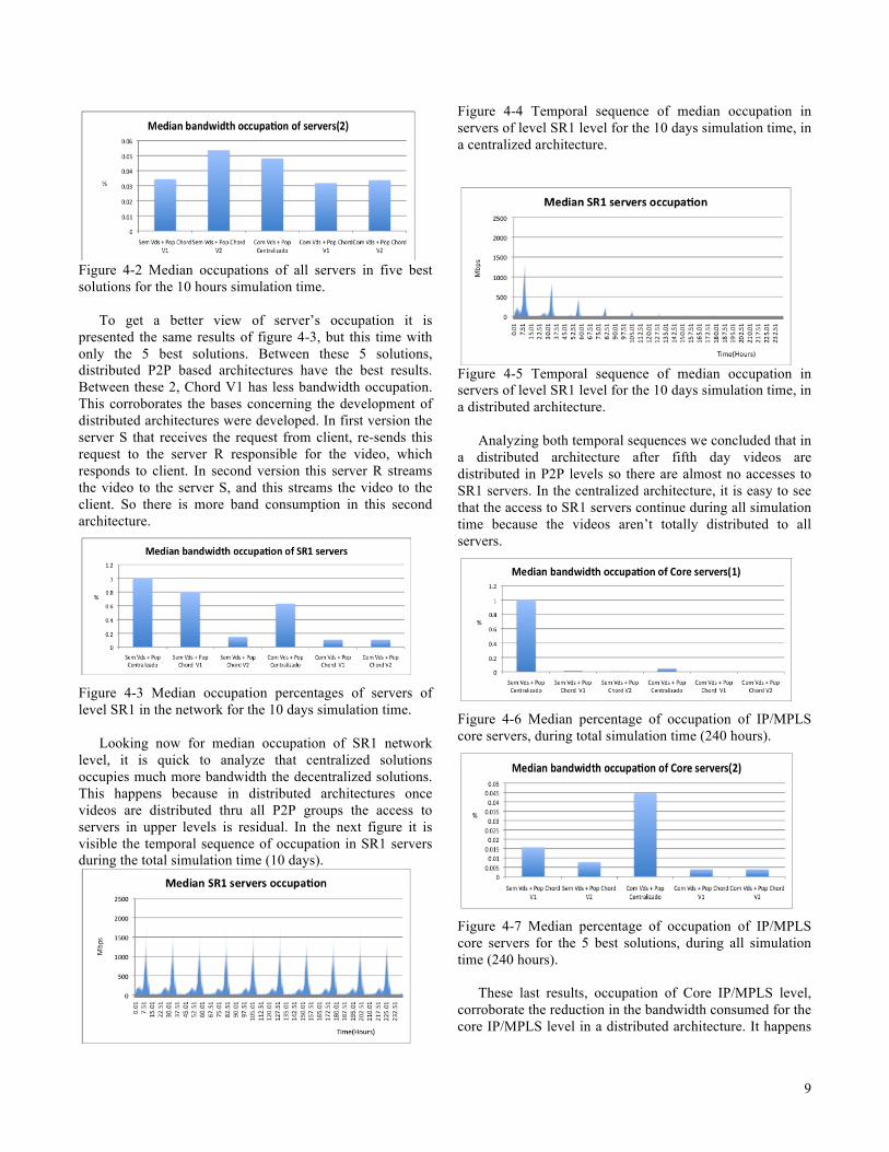
Figure 4-2 Median occupations of all servers in five best solutions for the 10 hours simulation time.
To get a better view of server’s occupation it is presented the same results of figure 4-3, but this time with only the 5 best solutions. Between these 5 solutions, distributed P2P based architectures have the best results. Between these 2, Chord V1 has less bandwidth occupation. This corroborates the bases concerning the development of distributed architectures were developed. In first version the server S that receives the request from client, re-sends this request to the server R responsible for the video, which responds to client. In second version this server R streams the video to the server S, and this streams the video to the client. So there is more band consumption in this second architecture.
Figure 4-3 Median occupation percentages of servers of level SR1 in the network for the 10 days simulation time.
Looking now for median occupation of SR1 network level, it is quick to analyze that centralized solutions occupies much more bandwidth the decentralized solutions. This happens because in distributed architectures once videos are distributed thru all P2P groups the access to servers in upper levels is residual. In the next figure it is visible the temporal sequence of occupation in SR1 servers during the total simulation time (10 days).
Figure 4-4 Temporal sequence of median occupation in servers of level SR1 level for the 10 days simulation time, in a centralized architecture.
Figure 4-5 Temporal sequence of median occupation in servers of level SR1 level for the 10 days simulation time, in a distributed architecture.
Analyzing both temporal sequences we concluded that in a distributed architecture after fifth day videos are distributed in P2P levels so there are almost no accesses to SR1 servers. In the centralized architecture, it is easy to see that the access to SR1 servers continue during all simulation time because the videos aren’t totally distributed to all servers.
Figure 4-6 Median percentage of occupation of IP/MPLS core servers, during total simulation time (240 hours).
Figure 4-7 Median percentage of occupation of IP/MPLS core servers for the 5 best solutions, during all simulation time (240 hours).
These last results, occupation of Core IP/MPLS level, corroborate the reduction in the bandwidth consumed for the core IP/MPLS level in a distributed architecture. It happens
10
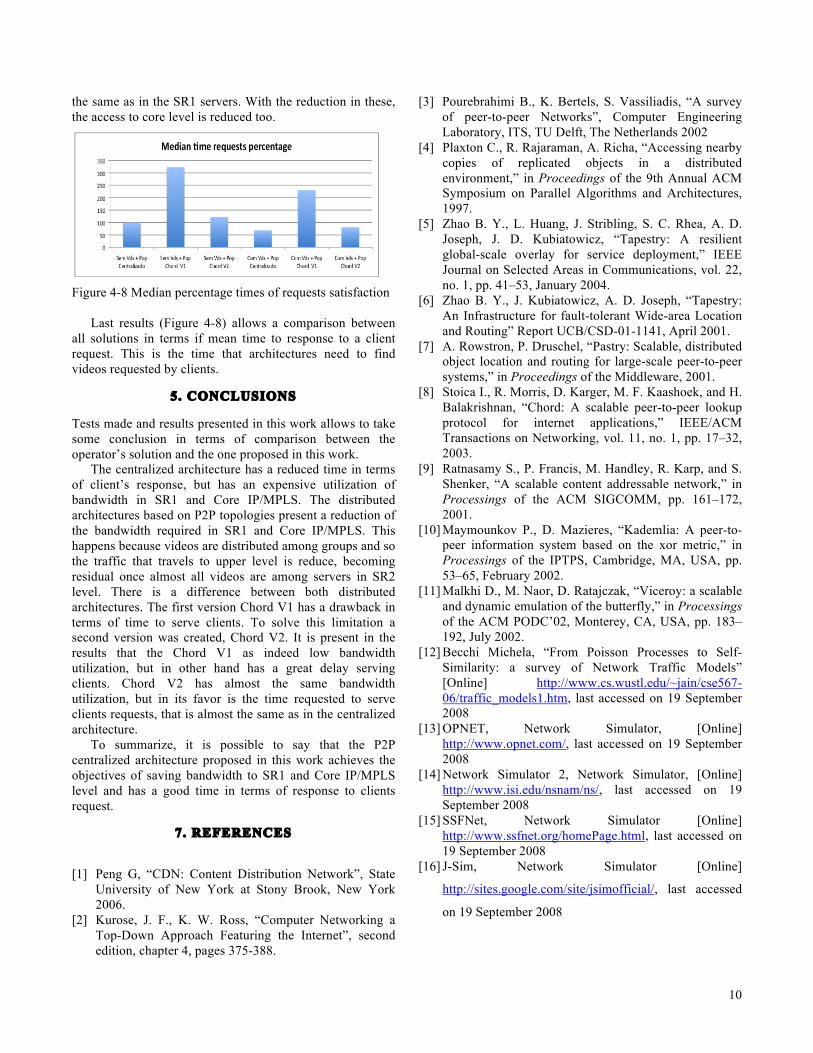
the same as in the SR1 servers. With the reduction in these, the access to core level is reduced too.
Figure 4-8 Median percentage times of requests satisfaction
Last results (Figure 4-8) allows a comparison between all solutions in terms if mean time to response to a client request. This is the time that architectures need to find videos requested by clients.
5. CONCLUSIONS
Tests made and results presented in this work allows to take some conclusion in terms of comparison between the operator’s solution and the one proposed in this work.
The centralized architecture has a reduced time in terms of client’s response, but has an expensive utilization of bandwidth in SR1 and Core IP/MPLS. The distributed architectures based on P2P topologies present a reduction of the bandwidth required in SR1 and Core IP/MPLS. This happens because videos are distributed among groups and so the traffic that travels to upper level is reduce, becoming residual once almost all videos are among servers in SR2 level. There is a difference between both distributed architectures. The first version Chord V1 has a drawback in terms of time to serve clients. To solve this limitation a second version was created, Chord V2. It is present in the results that the Chord V1 as indeed low bandwidth utilization, but in other hand has a great delay serving clients. Chord V2 has almost the same bandwidth utilization, but in its favor is the time requested to serve clients requests, that is almost the same as in the centralized architecture.
To summarize, it is possible to say that the P2P centralized architecture proposed in this work achieves the objectives of saving bandwidth to SR1 and Core IP/MPLS level and has a good time in terms of response to clients request.
7. REFERENCES
[1] Peng G, “CDN: Content Distribution Network”, State
University of New York at Stony Brook, New York 2006.
[2] Kurose, J. F., K. W. Ross, “Computer Networking a Top-Down Approach Featuring the Internet”, second edition, chapter 4, pages 375-388.
[3] Pourebrahimi B., K. Bertels, S. Vassiliadis, “A survey of peer-to-peer Networks”, Computer Engineering Laboratory, ITS, TU Delft, The Netherlands 2002
[4] Plaxton C., R. Rajaraman, A. Richa, “Accessing nearby copies of replicated objects in a distributed environment,” in Proceedings of the 9th Annual ACM Symposium on Parallel Algorithms and Architectures, 1997.
[5] Zhao B. Y., L. Huang, J. Stribling, S. C. Rhea, A. D. Joseph, J. D. Kubiatowicz, “Tapestry: A resilient global-scale overlay for service deployment,” IEEE Journal on Selected Areas in Communications, vol. 22, no. 1, pp. 41–53, January 2004.
[6] Zhao B. Y., J. Kubiatowicz, A. D. Joseph, “Tapestry: An Infrastructure for fault-tolerant Wide-area Location and Routing” Report UCB/CSD-01-1141, April 2001.
[7] A. Rowstron, P. Druschel, “Pastry: Scalable, distributed object location and routing for large-scale peer-to-peer systems,” in Proceedings of the Middleware, 2001.
[8] Stoica I., R. Morris, D. Karger, M. F. Kaashoek, and H. Balakrishnan, “Chord: A scalable peer-to-peer lookup protocol for internet applications,” IEEE/ACM Transactions on Networking, vol. 11, no. 1, pp. 17–32, 2003.
[9] Ratnasamy S., P. Francis, M. Handley, R. Karp, and S. Shenker, “A scalable content addressable network,” in Processings of the ACM SIGCOMM, pp. 161–172, 2001.
[10] Maymounkov P., D. Mazieres, “Kademlia: A peer-to-peer information system based on the xor metric,” in Processings of the IPTPS, Cambridge, MA, USA, pp. 53–65, February 2002.
[11] Malkhi D., M. Naor, D. Ratajczak, “Viceroy: a scalable and dynamic emulation of the butterfly,” in Processings of the ACM PODC’02, Monterey, CA, USA, pp. 183–192, July 2002.
[12] Becchi Michela, “From Poisson Processes to Self-Similarity: a survey of Network Traffic Models” [Online] http://www.cs.wustl.edu/~jain/cse567-06/traffic_models1.htm, last accessed on 19 September 2008
[13] OPNET, Network Simulator, [Online] http://www.opnet.com/, last accessed on 19 September 2008
[14] Network Simulator 2, Network Simulator, [Online] http://www.isi.edu/nsnam/ns/, last accessed on 19 September 2008
[15] SSFNet, Network Simulator [Online] http://www.ssfnet.org/homePage.html, last accessed on 19 September 2008
[16] J-Sim, Network Simulator [Online]
http://sites.google.com/site/jsimofficial/, last accessed