WK 421 610 Type UREP10 WK 421 610 05.2012 05.2012 - 1 - dm /min 3 A B a b T T P A B A B X Y 1 2 3 4 5 6 7 up to 31,5 MPa up to 150 NS10 Directional spool valve type UREP10 electro-hydraulically operated DATA SHEET - SERVICE MA MA MA MANUA NUA NUA NUAL APPLICATION DESCRIPTION OF OPERATION Directional spool valves type UREP10 UREP10 UREP10 UREP10… electro- hydraulically operated are intended for change in direction of fluid flow in a system and thus it allows to change direction of movement of a receiver - mostly piston rod of a cylinder or hydraulic motor as well to use functions: on and off. These directional spool valves are used for subplate mounting in any position in a hydraulic system. The directional spool valve type UREP10 UREP10 UREP10 UREP10… is complied with the regulations of directive 2006/95/WE 2006/95/WE 2006/95/WE 2006/95/WE for the following voltages: •50 50 50 50 – 250 V 250 V 250 V 250 V for AC AC AC AC •75 75 75 75 – 250 V 250 V 250 V 250 V for DC DC DC DC Main bore and annular ports P, T, A, B are made in the housing (1) and connected to its subplate connection. Directional valve is switched by shifting the spool (2) into one end position. Various control functions are dependent on the spool (2) which affects the change in configuration of connections among ports P, T, A, B in the housing (1). The spool (2) is shifted from its neutral position by affecting pressure of hydraulic fluid supplied via pilot valve (4) into one chamber of caps (3). The pilot valve (4) – type WE6… WE6… WE6… WE6… is operated by means of solenoids (5). The spool (2) is centered in neutral position by means of springs (7). In case of failure, the pilot valve (4) may be shifted manually by means of manual overrides (6) – version UREP10…/…N. 4UREP10 E 02/G24 N ET Z4
MMMMaaaax x x x operoperoperoperatatatatiiiing presng presng presng presssssureureureure
mineral oil
ReReReReqqqquuuuired fired fired fired f iiiiltrltrltrltratatatatiiiioooonnnn
Recommended filtration
up tup tup tup to o o o 11116666 µµµµmmmmup to 10 µm
Hydraulic fluid
Nominal fluid viscosity 2 o37 mm /s at temperature 55 C
22,8 up to 380 mm /so40 C up to 55 Co
o-20 C up to +70 Co
HydrHydrHydrHydraaaauuuullllic fic fic fic f lllluuuuidididid
- 20 C up to +50 Coo
0,0,0,0,5 5 5 5 MMMMPPPPaaaa
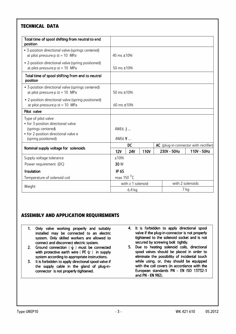
TECHNICAL DATA
Type UREP10 WK 421 610 05.2012- 3 -
TTTTooootatatatal tl tl tl time ime ime ime oooof spf spf spf spooooooool l l l sssshhhhififififtitititing frng frng frng from om om om neneneneuuuutratratratral tl tl tl to eo eo eo endndndnd
popopopossssititititiiiioooonnnn
TTTTooootatatatal tl tl tl time ime ime ime oooof spf spf spf spooooooool l l l sssshhhhififififtitititing frng frng frng fromomomom enenenendddd ttttoooo neneneneuuuutratratratrallll
popopopossssititititiiiioooonnnn
7 kg
with z 1 solenoid
6,4 kg
4WE6 Y Y Y Y ...
4WE6 J J J J ...
222233330000V V V V - - - - 55550000HHHHz z z z 111111110000V V V V - - - - 55550000HHHHzzzz11112222V V V V 22224444V V V V 111111110000VVVV
• 3-position directional valve (springs centered)
at pilot pressure p st = 10 MPa 40 ms ±10%
• 2-position directional valve (spring positioned) at pilot pressure p st = 10 MPa 50 ms ±10%
• 3-position directional valve (springs centered)
at pilot pressure p st = 10 MPa 50 ms ±10%
• 2-position directional valve (spring positioned) at pilot pressure p st = 10 MPa 60 ms ±10%
NNNNomomomomiiiinnnnaaaal l l l ssssuppuppuppupply ly ly ly vvvvooooltltltltage fage fage fage for or or or ssssoooolelelelennnnooooididididssssDDDDCCCC AAAACCCC (plug-in connector with rectifier)
Supply voltage tolerance ±10%
IIIInnnnssssuuuullllatatatatiiiioooonnnn I I I IP P P P 66665555
Power requirement (DC) 3 3 3 30000 W
Temperature of solenoid coil max 150 Co
PPPPiiiilllloooot vt vt vt vaaaallllveveveve
Type of pilot valve
• for 3-position directional valve
(springs centered)
• for 2-position directional valve e (spring positioned)
Weightwith 2 solenoids
TECHNICAL DATA
ASSEMBLY AND APPLICATION REQUIREMENTS
4.4.4.4. It is forbidden to It is forbidden to It is forbidden to It is forbidden to applyapplyapplyapply directional directional directional directional spool spool spool spool
valve valve valve valve ifififif the plug the plug the plug the plug----inininin----connectorconnectorconnectorconnector is not pr is not pr is not pr is not properoperoperoperly ly ly ly
tightened to the solenoid sockettightened to the solenoid sockettightened to the solenoid sockettightened to the solenoid socket and is not and is not and is not and is not
secured by screwing boltsecured by screwing boltsecured by screwing boltsecured by screwing bolt tig tig tig tighhhhtlytlytlytly....
5.5.5.5. Due to heating solenoid coils, directional Due to heating solenoid coils, directional Due to heating solenoid coils, directional Due to heating solenoid coils, directional
spool spool spool spool valves should be valves should be valves should be valves should be placed in orderplaced in orderplaced in orderplaced in order to to to to
eleleleliminate the possibility of incidental touch iminate the possibility of incidental touch iminate the possibility of incidental touch iminate the possibility of incidental touch
while using, or, they should be equipped while using, or, they should be equipped while using, or, they should be equipped while using, or, they should be equipped
with the coil covers with the coil covers with the coil covers with the coil covers (in accordancein accordancein accordancein accordance withwithwithwith thethethethe
EuropeanEuropeanEuropeanEuropean standards standards standards standards PNPNPNPN ---- EN EN EN EN ISOISOISOISO 13732137321373213732----1111
andandandand PNPNPNPN ---- EN 982EN 982EN 982EN 982)....
1.1.1.1. Only valve working properly and suitably Only valve working properly and suitably Only valve working properly and suitably Only valve working properly and suitably
installed may be connected to an electric installed may be connected to an electric installed may be connected to an electric installed may be connected to an electric
system. Only skilled workers are allowed to system. Only skilled workers are allowed to system. Only skilled workers are allowed to system. Only skilled workers are allowed to
connect and disconnect electric system.connect and disconnect electric system.connect and disconnect electric system.connect and disconnect electric system.
2.2.2.2. Ground connection Ground connection Ground connection Ground connection ( ) must must must must bebebebe connected connected connected connected
with protective earth wire with protective earth wire with protective earth wire with protective earth wire ( PEPEPEPE ) in supply in supply in supply in supply
system according to system according to system according to system according to appropriate appropriate appropriate appropriate instructions.instructions.instructions.instructions.
3.3.3.3. It is forbidden to It is forbidden to It is forbidden to It is forbidden to applyapplyapplyapply directional directional directional directional spool spool spool spool valve valve valve valve if if if if
the supply cable in thethe supply cable in thethe supply cable in thethe supply cable in the gland gland gland gland of plugof plugof plugof plug----inininin----
connector connector connector connector is not is not is not is not properly tightenedproperly tightenedproperly tightenedproperly tightened....
Type UREP10WK 421 610 05.2012 - 4 -
b, Y
A B
P TX Y
a b
a, X a b
a b
A B
P T
a b
a b
A B
P T
a b
X
b, Y
A B
P TX Y
a b
a, X a b
a b
A B
P T
a b
Y
b, Y
A B
P TX Y
a b
a, X a b
a b
A B
P T
a b
X Y
b, Y
A B
P TX Y
a b
a, X a bb, Y
A B
P TX Y
a b
a, X a b0
a b
A B
P T
a b0
Y
a b
A B
P T
a b0
X
a b
A B
P T
a b0
YX
b, Y
A B
P TX Y
a b
a, X a b0
b, Y
A B
P TX Y
a b
a, X a b0
b, Y
A B
P TX Y
a b
a, X a b0
a b
A B
P T
a b0
3-position directional valves with springs centered
spool at 0000 position (spool schemes: EEEE, FFFF, GGGG, HHHH, JJJJ, LLLL,
MMMM, UUUU, WWWW)
exexexextttternaernaernaernallll supply XXXX ; exexexextttternaernaernaernallll drain Y Y Y Y
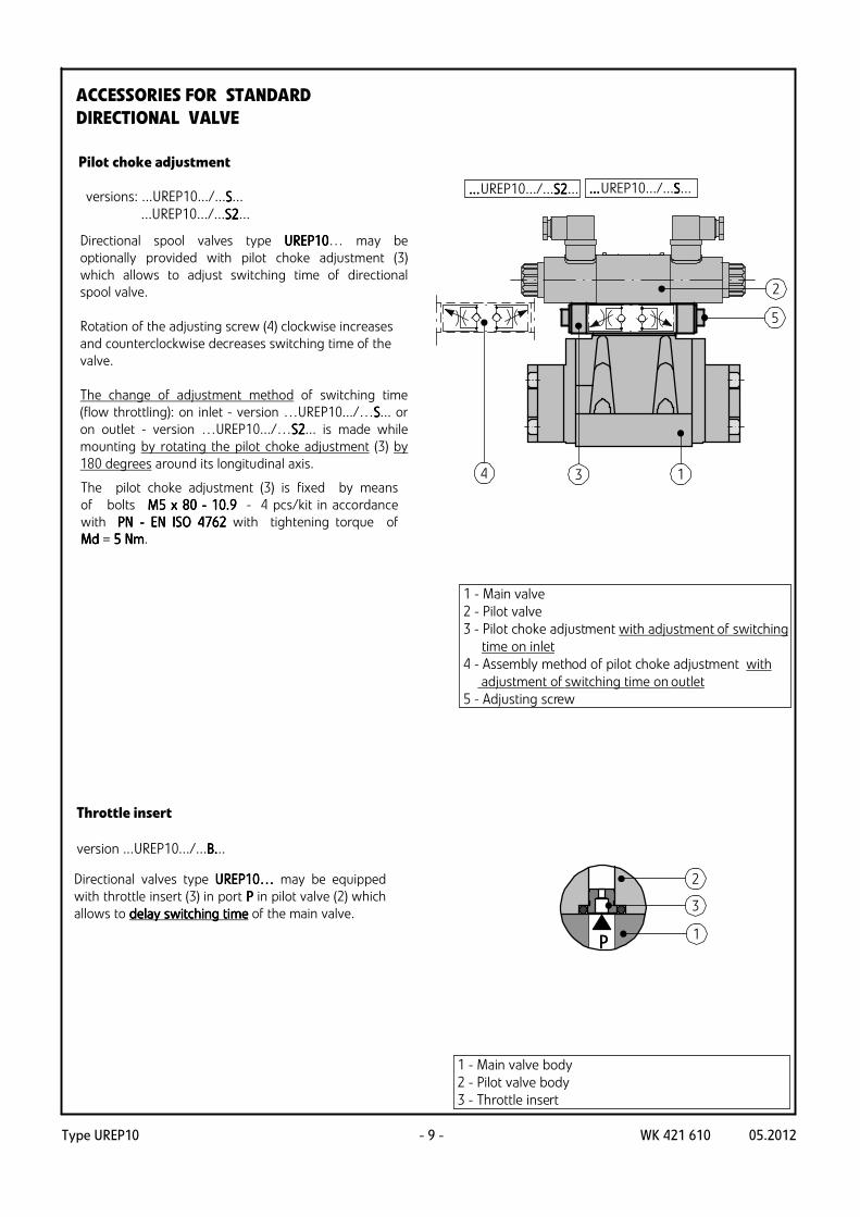
version ...UREP10.../...
iiiinnnntttternaernaernaernallll supply XXXX ; exexexextttternaernaernaernallll drain Y Y Y Y
version ...UREP10.../...EEEE...
iiiinnnnternternternternaaaallll supply XXXX ; iiiinnnntttternaernaernaernallll drain Y Y Y Y
version ...UREP10.../...EEEETTTT...
exexexextttternaernaernaernallll supply XXXX ; iiiinnnntttternaernaernaernallll drain Y Y Y Y
version ...UREP10.../...TTTT...
2-position directional valves with spring positioned
spool (spool schemes: CCCC, DDDD)
exexexextttternaernaernaernallll supply XXXX ; exexexextttternaernaernaernallll drain Y Y Y Y
version ...UREP10.../...
iiiinnnntttternaernaernaernallll supply XXXX ; exexexextttternaernaernaernallll drain Y Y Y Y
version ...UREP10.../...EEEE...
iiiinnnnternternternternaaaallll supply XXXX ; iiiinnnntttternaernaernaernallll drain Y Y Y Y
version ...UREP10.../...EEEETTTT...
exexexextttternaernaernaernallll supply XXXX ; iiiinnnntttternaernaernaernallll drain Y Y Y Y
version ...UREP10.../...TTTT...
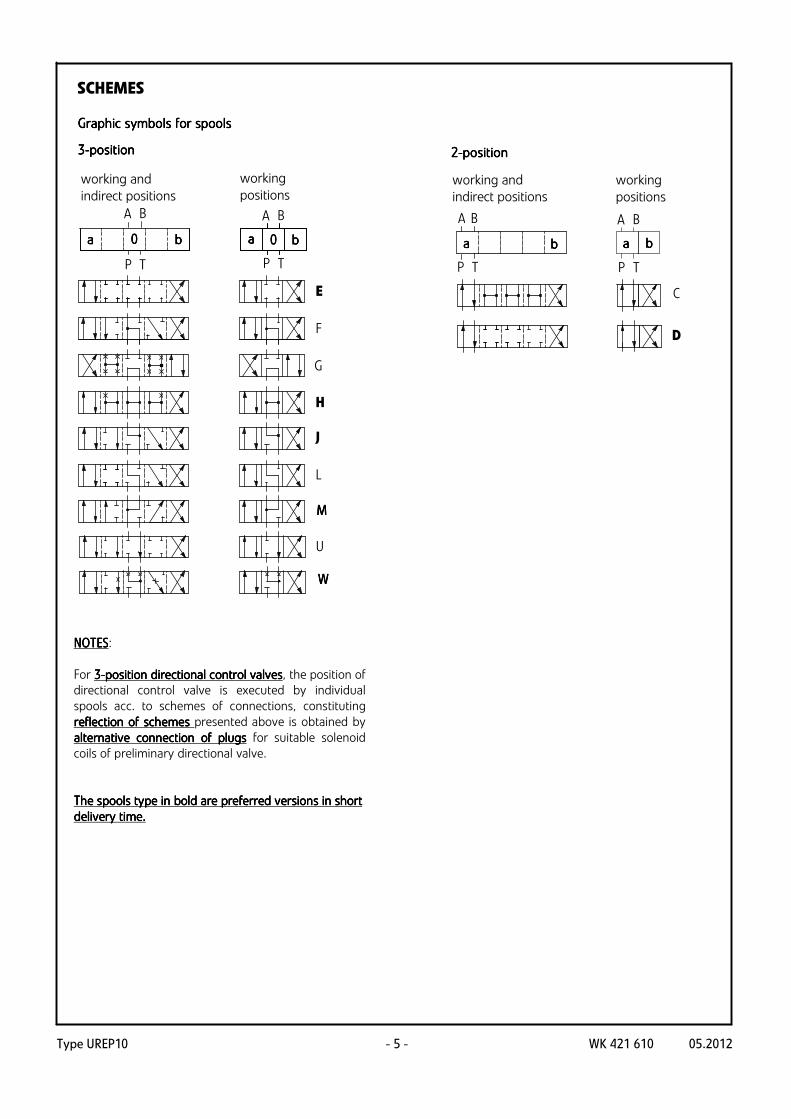
SCHEMES
SSSSimpimpimpimpllllifififified ied ied ied aaaand detnd detnd detnd detaaaaiiiiled led led led hydrhydrhydrhydraaaauuuullllic scic scic scic schemes fhemes fhemes fhemes forororor
directdirectdirectdirect iiiioooonnnnaaaal l l l vvvvaaaallllves ves ves ves wwwwitititith h h h vvvvarararariiiioooouuuus ps ps ps piiiilllloooot st st st suppuppuppupplylylyly (XXXX)
For 3333----position directional control valvesposition directional control valvesposition directional control valvesposition directional control valves, the position of
directional control valve is executed by individual
spools acc. to schemes of connections, constituting
reflection of schemes reflection of schemes reflection of schemes reflection of schemes presented above is obtained by
alternative connection of plugsalternative connection of plugsalternative connection of plugsalternative connection of plugs for suitable solenoid
coils of preliminary directional valve.
The spools type in bold are preferred versions in short The spools type in bold are preferred versions in short The spools type in bold are preferred versions in short The spools type in bold are preferred versions in short
EEEE, GGGG, HHHH, J J J J, L L L L, MMMM, U U U U,
WWWW, C C C C, D D D D
21 MPa 31,5 MPa
pressure pppp
120 100
150FFFF
spool type
120
flow rate QQQQmax
dm /min3
dm /min3
dm /min3
dm /min3
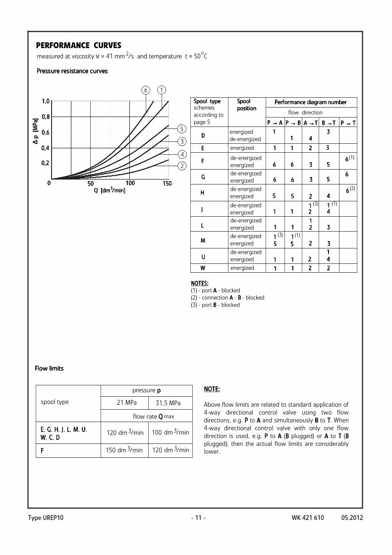
PERFORMANCE CURVES
measured at viscosity ν = 41 mm /s and temperature t = 50 C2 o
PressPressPressPressure resure resure resure res iiiiststststaaaance cnce cnce cnce cururururvesvesvesves
FlFlFlFloooow w w w llllimimimimititititssss
NOTE: NOTE: NOTE: NOTE:
Above flow limits are related to standard application of
4-way directional control valve using two flow
directions, e.g. PPPP to A A A A and simultaneously BBBB to TTTT. When
4-way directional control valve with only one flow
direction is used, e.g. PPPP to AAAA (BBBB plugged) or AAAA to TTTT (BBBB
plugged), then the actual flow limits are considerably
lower.
Type UREP10WK 421 610 05.2012 - 12 -
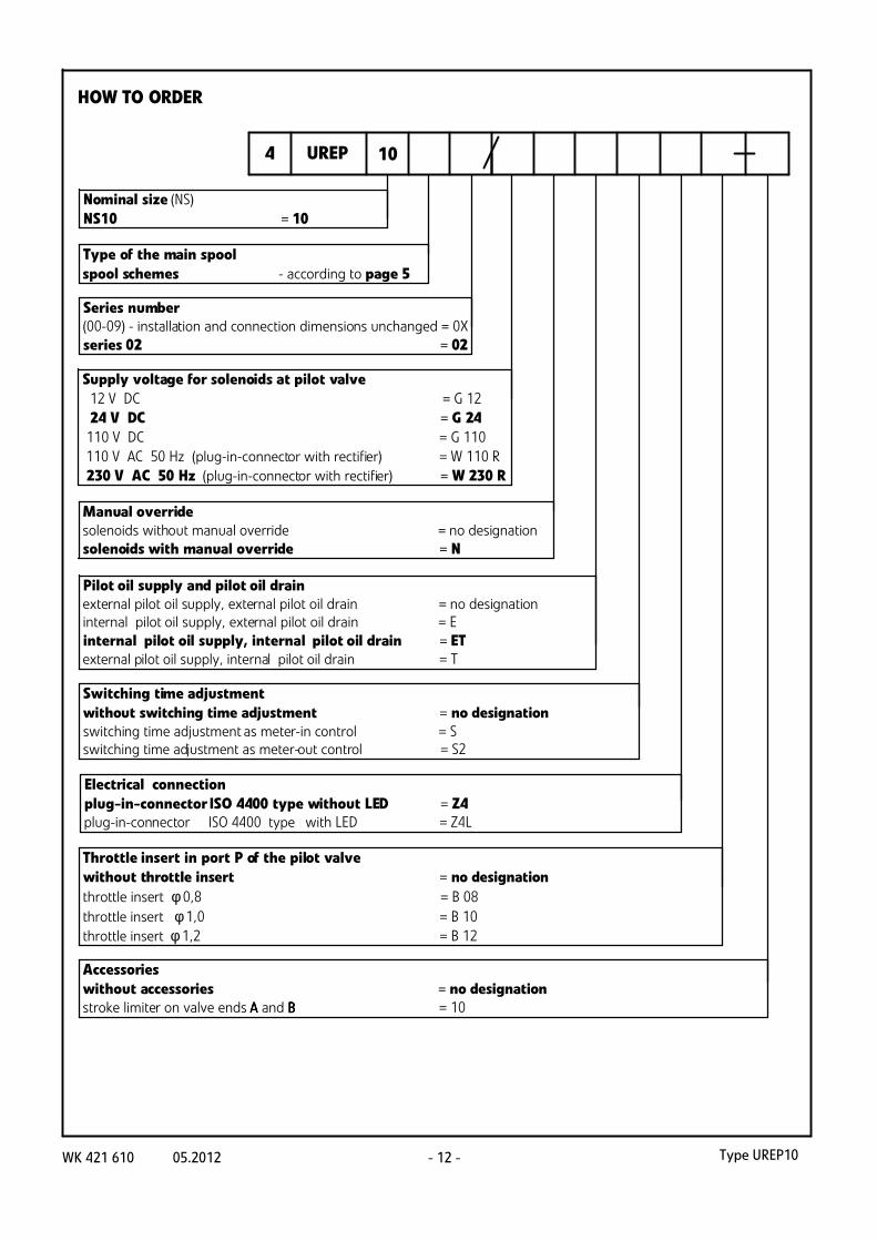
UREP 10
Supply voltage for solenoids at pilot valve
12 V DC = G 12
24 V DC = G 24
110 V DC = G 110
110 V AC 50 Hz (plug-in-connector with rectifier) = W 110 R
230 V AC 50 Hz (plug-in-connector with rectifier) =W 230 R
Pilot oil supply and pilot oil drain
external pilot oil supply, external pilot oil drain = no designation
internal pilot oil supply, external pilot oil drain = E
internal pilot oil supply, internal pilot oil drain = ET
external pilot oil supply, internal pilot oil drain = T
Switching time adjustment
without switching time adjustment = no designation
switching time adjustment as meter-in control = S
switching time adjustment as meter-out control = S2
Type of the main spool
spool schemes - according to page 5
Series number
(00-09) - installation and connection dimensions unchanged = 0X
series 02 = 02
Nominal size (NS)
NS10 = 10
Manual override
solenoids without manual override = no designation
solenoids with manual override = N
Throttle insert in port P of the pilot valve
without throttle insert = no designation
throttle insert φ 0,8 = B 08
throttle insert φ 1,0 = B 10
throttle insert φ 1,2 = B 12
Electrical connection
plug-in-connector ISO 4400 type without LED = Z4
plug-in-connector ISO 4400 type with LED = Z4L
Accessories
without accessories = no designation
stroke limiter on valve ends AAAA and BBBB = 10
4
HOW TO ORDER
Type UREP10 WK 421 610 05.2012- 13 -
* Further requirements in clear text
(to be agreed with the manufacturer)
Sealing
NBR (for fluids on mineral oil base) = no designation
FKM (for fluids on phosphate ester base) = V
HOW TO ORDER
NNNNOOOOTTTTEEEES:S:S:S:
The directional spool valve should be ordered according to the above coding.
TTTThe he he he symbosymbosymbosymbolllls s s s iiiin bn bn bn boooold ld ld ld are preferred versare preferred versare preferred versare preferred vers iiiioooonnnns s s s iiiin n n n sssshhhhort deort deort deort delllliiiivery tvery tvery tvery t ime.ime.ime.ime.