ROTARY DMP 7-8 USER’S AND MAINTENANCE MANUAL Edition March 2010 - � Pagina 2 di 50
Contents Section 1 – General information ................................................................................................................................................................... 3 Section 2 – Use of the manual ..................................................................................................................................................................... 4 Section 3 – Machine assembly .................................................................................................................................................................... 6 Section 4 – Attachment of the machine to the tractor ................................................................................................................................. 14 Section 5 – Cardan shaft ........................................................................................................................................................................... 18 Section 6 – Transport position ................................................................................................................................................................... 19 Section 7 – Work position and adjustments ............................................................................................................................................... 21 Section 8 – Use of the mowing machine .................................................................................................................................................... 23 Section 9 – Adjustments for operation ....................................................................................................................................................... 24 Section 10 – Checks, maintenance, adjustments. ...................................................................................................................................... 27 Section 11 - Lubrication ............................................................................................................................................................................. 31 Section 12 – Requesting spare parts ......................................................................................................................................................... 35
This document is the property of ENOAGRICOLA ROSSI s.r.l. No parts herein may be reproduced without prior consent from the Company Management. Any infringements will be punished by law.
ROTARY DMP 7-8 USER’S AND MAINTENANCE MANUAL Edition March 2010 - � Pagina 3 di 50
Section 1 – General information
Assistance For any needs, contact the machine dealer or the ENOAGRICOLA ROSSI Technical Office.
CE Marking This mark certifies that the machine complies with the safety requirements set by the European Union.
ENOAGRICOLA ROSSI
06018 Calzolaro di Umbertide-Perugia-Italy
ROTARY DISC MOWER
CE Conformity declaration ENOAGRICOLA ROSSI srl 06018 Calzolaro di Umbertide-Perugia-Italy
declares under its exclusive responsibility that the machine ROTARY DISC MOWER
to which this declaration refers, conforms to the essential safety requirements established by Directives 89/392/EEC, 91/368/EEC,
93/44/EEC, 93/68/EEC.
The legal representative
ROTARY DMP 7-8 USER’S AND MAINTENANCE MANUAL Edition March 2010 - � Pagina 4 di 50
Section 2 – Use of the manual
BEFORE INSTALLING AND USING THE MACHINE
OR BEFORE CARRYING OUT ANY OPERATION
READ CAREFULLY THE INSTRUCTIONS CONTAINED IN THIS M ANUAL ����
This manual has been written for your safety. It is an integral part of this machine and must be kept for reference at all
times, protecting it from moisture, neglect, and sunlight in order to prevent its deterioration.
The manual is intended for: the machine users, the owner, the safety supervisors, those in charge of handling, installation, use, supervision, maintenance, and final dismantling.
The manual provides indications on the correct use of the machine, its technical features, and safety measures; this
manual, in any case, can never replace an adequate experience of the user.
The manual also gives information for personnel training, for guiding maintenance operations, facilitating the request for spare parts, and warning about remaining risks that could not be eliminated in the design phase.
The manual reflects the state of the machine’s technical status as sold and cannot be considered inadequate if
subsequently updated on the basis of new experience.
The company supplying the machine reserves the right to make any changes to the product and its manual without the obligation to update previous production and related manuals.
N.B. Enoagricola Rossi accepts no liability for damages resulting from improper use by untrained personnel, use not in
accordance with national and Community workplace safety requirements, incorrect installation, serious deficiencies in the required maintenance, unauthorized changes or repairs, use of unauthorised spare parts, acts of God, or total or partial failure to follow the instructions contained in this manual.
ROTARY DMP 7-8 USER’S AND MAINTENANCE MANUAL Edition March 2010 - � Pagina 5 di 50
The machine has been designed in conformity with European machine safety standards and, in particular, the following standards have been considered: 1. EN 292/2 Ed. 1991: Safety of machine. Fundamental concepts and general principles of mechanical design. Technical
specifications and principles. 2. ISO 7000 Ed. 1994: Safety decals to be used on machine.
The machine must be used by operators who: 1. Have a good knowledge of safety standards and regulations. 2. Are well informed on risks of this machine and dangerous areas and on the importance of not tampering with protection
guards. 3. Have been well trained on how to operate the machine. 4. Will inform manufacturer of any malfunctioning.
���� In the event this manual is lost or damaged, a new copy may be requested from this address:
IMPORTANT! If the machine is sold, please turn this manual over to the new owner.
ROTARY DMP 7-8 USER’S AND MAINTENANCE MANUAL Edition March 2010 - � Pagina 6 di 50
Section 3 – Machine assembly
To facilitate shipments of the machines, several parts have been disassembled to reduce the shipping dimensions. To reassemble, proceed as follows:
• Open the case and lay the mower disc bar flat as indicated in Fig. 1.
• Turn the frame and the 3rd point using a lifting device (hoist, lift truck, etc.) and position the mower disc bar as in Fig. 2
Fig. 1
Fig. 2
ROTARY DMP 7-8 USER’S AND MAINTENANCE MANUAL Edition March 2010 - � Pagina 7 di 50
1st assembly – assembly of the protection support. Mount protection support A (Fig. 3 – Fig. 3/A) in gear case B; first of all, connect the lifting rod hole to support D (Fig. 3). Fasten the support with screws C (screw T.E. M12x50 and washer M12 Y and spacer J.
2nd assembly – assembly of the protection bar (only on DM-P series). Position the protection bar E in support A (Fig. 4) and fasten it with six screws F (screw T.E. M10x35), six washers, and six self-locking nuts G M10 (only on DM-P series).
Fig. 3/A
Fig. 3
Fig. 4
ROTARY DMP 7-8 USER’S AND MAINTENANCE MANUAL Edition March 2010 - � Pagina 8 di 50
3rd assembly – support rod.
Mount support rod H (Fig. 5), and fasten with screws M (T.E. M12x90 + self locking nut), and screws N (T.E. M10x30 + self locking nut M10)
4th assembly – assembly of the side rake disc. Fasten rake disc unit I on the central bar M (Fig. 5). Fasten it using screws P ( T.E.M10x70 + self locking nut M10) and plate Z ( 115x95x10)
Make sure the rake disc does not touch the cone cover and blades. Observe the safety distance X= from 15 to 25 mm. (Fig. 6).
Fig. 5
Fig. 6
ROTARY DMP 7-8 USER’S AND MAINTENANCE MANUAL Edition March 2010 - � Pagina 9 di 50
5th assembly – assembly of the internal cone disc. Mount internal cone disc M (Fig. 7) so that the largest dimension is oriented perpendicular to that of the nearby disc.
6th assembly – assembly of the lower slide and protect ion plate. Lift the mower and mount the lower slide N (Fig. 8) and slide tip O. Fasten them with four screws P (T.E. 12x30 + self-locking nuts + washer) and two screws Q (TTQS M10x25 + washer + self locking nut).
Fig. 7
Fig. 8
ROTARY DMP 7-8 USER’S AND MAINTENANCE MANUAL Edition March 2010 - � Pagina 10 di 50
7th assembly – assembly of internal protective flap. Mount flap R (Fig. 9) protecting the gear case and fasten it with connecting bracket S and three screws T (TTQS M10x25 + washer + self locking nut). To facilitate assembly of flap R, it is advisable to insert all screws before starting to tighten them.
8th assembly – assembly of the belt protection case. Mount case U (Fig. 10), fasten with screws V (T.E. M10x120), washers and self-blocking nuts (M10).
Fig. 9
Fig. 10
ROTARY DMP 7-8 USER’S AND MAINTENANCE MANUAL Edition March 2010 - � Pagina 11 di 50
9th assembly – compensating spring. Hook spring W (Fig. 11) on pin Y of the protection support and fasten it with an elastic pin Ø 6x40.
To facilitate this operation, attach the machine to the tractor, lifting it until the support hole is aligned with pin Y (Fig. 11).
10th assembly – assembly of the release cord. Insert cord A (Fig. 12) through ring B, then fasten the hook to safety hook C. Close the hook with a pliers. Insert cord D through ring E and tie safety hook C (Fig. 13), making a knot in the hole.
Mount hydraulic pipe G on the hydraulic piston, with the perforated screw, positioning the copper washers (Fig. 13).
Fig. 11
Fig. 12
Fig. 13
ROTARY DMP 7-8 USER’S AND MAINTENANCE MANUAL Edition March 2010 - � Pagina 12 di 50
11th assembly – assembly of protection guards. Mount front guard H (Fig. 14) on the three hinges and fasten with screws I (T.E. M12x100) and self-locking nuts M10 + washer.
Mount rear guard L with six screws M (TTQS M10x25) and self-locking nuts M10.
Assemble the protection guard frame and fasten it to the supporting structure using the ties found under the tarpaulin (Fig. 15).
Assemble the protection rod for tarpaulin N (Fig. 17) and at the same time assemble (Fig. 16) front handle O and rear handle P. Fasten rear handle P with screws Q (TTQS M10x35), washers, and self-locking nuts M10.
Fig. 14
Fig. 15
Fig. 16
Fig. 17
ROTARY DMP 7-8 USER’S AND MAINTENANCE MANUAL Edition March 2010 - � Pagina 13 di 50
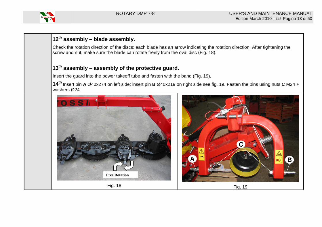
12th assembly – blade assembly.
Check the rotation direction of the discs; each blade has an arrow indicating the rotation direction. After tightening the screw and nut, make sure the blade can rotate freely from the oval disc (Fig. 18).
13th assembly – assembly of the protective guard. Insert the guard into the power takeoff tube and fasten with the band (Fig. 19).
14th Insert pin A Ø40x274 on left side; insert pin B Ø40x219 on right side see fig. 19. Fasten the pins using nuts C M24 + washers Ø24
Fig. 18
Fig. 19
Free Rotation
ROTARY DMP 7-8 USER’S AND MAINTENANCE MANUAL Edition March 2010 - � Pagina 14 di 50
Section 4 – Attachment of the machine to the tracto r NB: The mower must be attached to a tractor with a power takeoff of 540
rpm and to a 3-point attachment (Fig. 20).
Fig. 20
Instructions for attachment to the tractor:
Fig. 21
1) Insert the tractor’s lifting arms A (Fig. 20) into attachment pins B and fasten them with split pins.
2) Insert 3rd point C and fasten it with pin D (Fig. 20).
3) Connect the hydraulic pipe of the piston to the tractor’s distributor (Fig. 21)
ROTARY DMP 7-8 USER’S AND MAINTENANCE MANUAL Edition March 2010 - � Pagina 15 di 50
4) Connect the tractor’s cardan shaft to the power takeoff of the mower;
use chains to prevent rotation of the protection pipe.
Fig. 22
5) Lift the machine using the hydraulic lift; turn edge E upwards (Fig. 22)
6) IMPORTANT!!! During work and transport, edge E must always be turned upwards as in Fig. 23.
Fig. 23
ROTARY DMP 7-8 USER’S AND MAINTENANCE MANUAL Edition March 2010 - � Pagina 16 di 50
7) ADJUSTMENT OF FRAME HEIGHT FROM THE GROUND.
A - for tractors equipped with hydraulic lift position control:
Position the tractor on level ground and lower the hydraulic lift until the lifting lever F is positioned at a distance of 4 mm from the edge, as shown in Fig. 24.
Fig. 24
After adjusting the height of the mower frame, set the lift control from the tractor driver’s seat. In this case it is not necessary to use the limiting chain supplied with the machine.
ROTARY DMP 7-8 USER’S AND MAINTENANCE MANUAL Edition March 2010 - � Pagina 17 di 50
B – for tractors not equipped with hydraulic lift posit ion control:
The chain supplied with the machine must be used.
Fasten bracket G (Fig. 25) and the limiting chain H supplied, to one of the free holes of the tractor’s third point.
Lower the machine to work position, until lifting lever F is positioned at a distance of 4 mm from the edge, as shown in Fig. 24. Limiting chain H must be taut (Fig. 25), and the lifting lever must be at a distance of 4 mm. as per Fig. 24.
To be able to always recognize this position, mark the chain ring that will be hooked with bracket G.
Fig. 25
ROTARY DMP 7-8 USER’S AND MAINTENANCE MANUAL Edition March 2010 - � Pagina 18 di 50
Section 5 – Cardan shaft
The cardan shaft supplied with the mower is of the correct size for coupling with most tractors on the market. In any case, before starting work for the first time, it is advisable to check its length. If adaptation is required, proceed as follows: Important! Use only the cardan shaft supplied or recommended, otherwise any warranty claim or request will be considered null and void. If the cardan shaft is too long, open the two halves and overlap them; this way it will be possible to determine how much longer it is in cm. Cut both tubes of the internal and external cardan shaft to the same length, as well as their guards. Clean the cut edges of the tubes with a file, grease them, and reclose the cardan shaft. Important! The maximum work length (L1) must allow an overlapping of the tubes equal to half the length of the closed cardan shaft (min. _X). Always make sure that the cardan shaft is correctly tightened before starting work Support chain Use the chain to prevent rotation of the protection tube. Make sure that the chain does not hamper the side movements of the cardan shaft.
ROTARY DMP 7-8 USER’S AND MAINTENANCE MANUAL Edition March 2010 - � Pagina 19 di 50
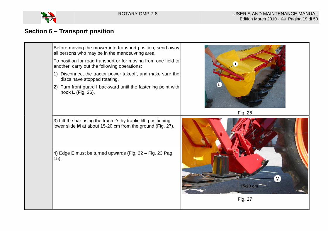
Section 6 – Transport position
Before moving the mower into transport position, send away all persons who may be in the manoeuvring area.
To position for road transport or for moving from one field to another, carry out the following operations:
1) Disconnect the tractor power takeoff, and make sure the discs have stopped rotating.
2) Turn front guard I backward until the fastening point with hook L (Fig. 26).
Fig. 26
3) Lift the bar using the tractor’s hydraulic lift, positioning lower slide M at about 15-20 cm from the ground (Fig. 27).
Fig. 27
4) Edge E must be turned upwards (Fig. 22 – Fig. 23 Pag. 15).
ROTARY DMP 7-8 USER’S AND MAINTENANCE MANUAL Edition March 2010 - � Pagina 20 di 50
5) Pull cord O to free lifting lever P (Fig. 28).
Fig. 28
6) Slowly lift the mower to a vertical position, using the hydraulic hitch. Release the traction of cord O (Fig. 29) while raising the bar vertically; it will automatically hook up, for transport, with safety hook P1.
Fig. 29
ROTARY DMP 7-8 USER’S AND MAINTENANCE MANUAL Edition March 2010 - � Pagina 21 di 50
Section 7 – Work position and adjustment Before moving the mower into the work position, send away
all persons who may be in the manoeuvring area.
To switch the bar from transport position to work position, carry out the following operations:
1) give pressure to the hydraulic hitch to lighten the weight on safety hook P1 (Fig. 30).
Fig. 30
2) Pull cord O to free the bar from safety hook P1 (Fig. 30).
3) Lower the mower using the hydraulic cylinder until it reaches the work position.
ROTARY DMP 7-8 USER’S AND MAINTENANCE MANUAL Edition March 2010 - � Pagina 22 di 50
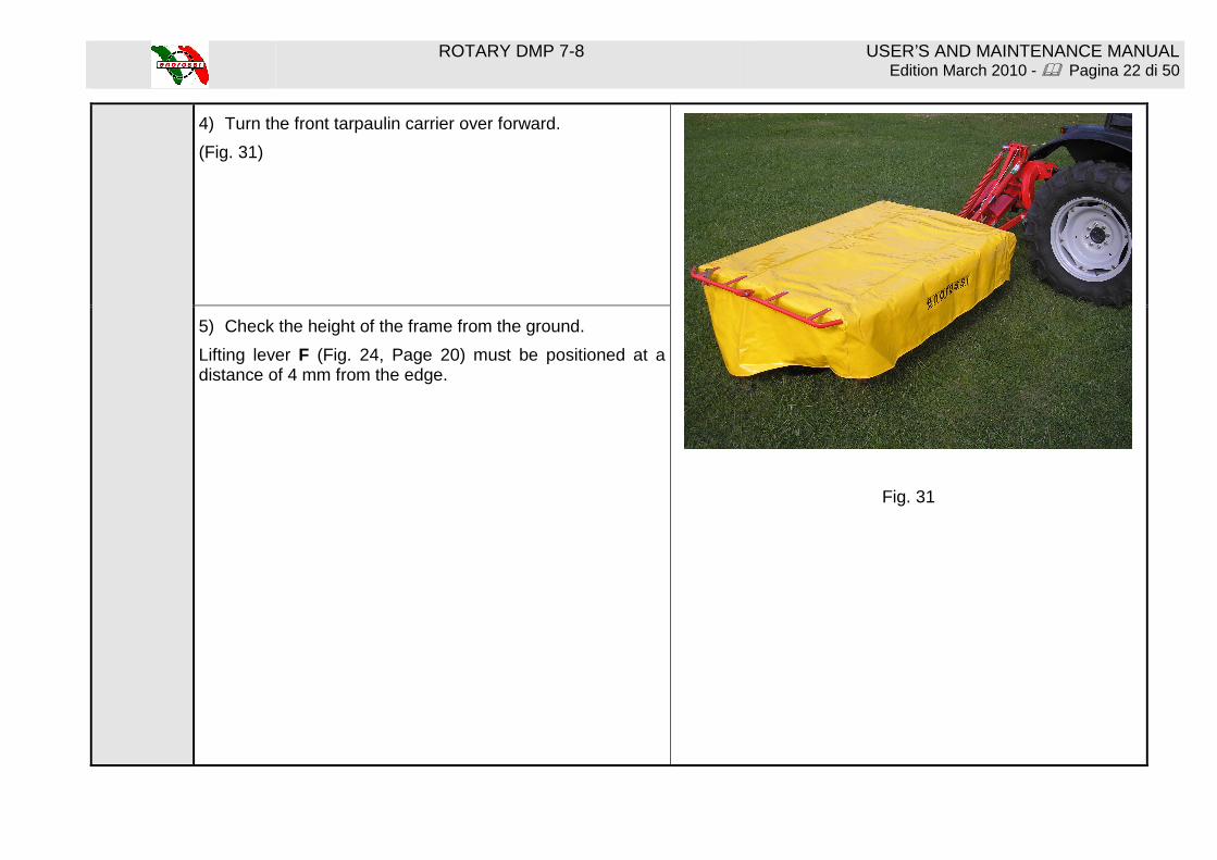
4) Turn the front tarpaulin carrier over forward.
(Fig. 31)
Fig. 31
5) Check the height of the frame from the ground.
Lifting lever F (Fig. 24, Page 20) must be positioned at a distance of 4 mm from the edge.
ROTARY DMP 7-8 USER’S AND MAINTENANCE MANUAL Edition March 2010 - � Pagina 23 di 50
Section 8 – Use of the mowing machine
Before starting work, make sure that there are no persons close to the work area.
Check that protective guards are lowered and the protective tarpaulin is covering the cutting bar.
At this point, carry out the manoeuvres listed below:
1) Connect the tractor’s power takeoff and accelerate progressively until reaching 540 rpm.
2) The advancement speed must be appropriate for the working conditions. Reduce speed when changing direction.
3) When work is finished, gradually reduce the speed of the power takeoff, then disconnect it.
IMPORTANT!!!! Do not mow in extremely stony or rocky areas.
4) During work, the tractor’s hydraulic distributor must always be in floating position in order to permit an adequate adaptability to the irregularities of the terrain.
The mowing bar can be raised from the ground using the hydraulic cylinder (Fig. 32).
5) Raise the mowing bar using the hydraulic cylinder until the cylinder edge R reaches its limit (Fig. 33).
Fig. 32
Fig. 33
ROTARY DMP 7-8 USER’S AND MAINTENANCE MANUAL Edition March 2010 - � Pagina 24 di 50
Section 9 – Adjustments for operation
Adjustment of the side rake disc. Position the rake disc in order to have the greatest distance between the uncut forage and the windrow.
To set the disc in the correct position loosen the 4 screws pos. A and move to right or left the disc support see fig.34. Once you reach the right position fasten the 4 screws pos. A
Fig. 34
Adjustment of cutting height. The maximum and minimum cutting heights are obtained by changing the tilt of the mowing bar, by varying the length of the third point C (Fig. 35), until the desired cutting height is obtained. The minimum height must be no less than 30 mm.
Fig. 35
ROTARY DMP 7-8 USER’S AND MAINTENANCE MANUAL Edition March 2010 - � Pagina 25 di 50
Adjustment of the safety hook.
If the mowing bar hits an obstacle during work, the safety hook opens and allows the mowing bar to shift backward. In this case, immediately stop the tractor and disconnect the power takeoff.
The safety hook is rehooked by backing up.
NB: Check that all moving parts are well greased. I f an obstacle is struck, check to make sure the mowing b ar has not been damaged (Fig. 36).
Fig. 36
The distance T of the washers to spring A must be 95 mm (Fig. 37).
Fig. 37
ROTARY DMP 7-8 USER’S AND MAINTENANCE MANUAL Edition March 2010 - � Pagina 26 di 50
Detachment of the machine from the tractor.
1) Using the hydraulic hitch, lower the disc mower to a horizontal position. Unlock edge N and turn it downwards (see arrow) onto transfer case U (Fig. 38 – Fig. 39).
Fig. 38
Fig. 39
2) Lower the tractor’s hydraulic lift, to lower the machine to the ground.
3) Disconnect the third point and remove the hydraulic tube, closing the tap V (Fig. 40).
Fig. 40
4) Disconnect the towing bars and cardan shaft.
ROTARY DMP 7-8 USER’S AND MAINTENANCE MANUAL Edition March 2010 - � Pagina 27 di 50
Section 10 – Checks, maintenance, adjustments.
IMPORTANT!!! Before proceeding with any maintenance or adjustment, turn off the tractor engine, remove the keys, and disconnect the cardan shaft.
1) Checking of discs and blades. The discs, blades, and fastening screws are made of a special high-quality steel and heat-treated to increase their durability and resistance to wear.
Worn or damaged parts must be immediately replaced with original ENOROSSI parts, otherwise it will not be possible to make any warranty claims or requests.
2) Checking of blade-carrying pins. Make regular checks of the condition of the blade pins every 50 work hours, and check them more often if work is done on rocky terrain or in difficult conditions.
Check them immediately in the case of violent blows (stones, pieces of wood, etc.).
Replace the blade pin if it is deformed or deteriorated.
Replace the blade pin if the screw head is worn or deteriorated.
Replace the blade pin if the screw head measures less than 13-15 mm (D) (Fig. 41).
Fig. 41
ROTARY DMP 7-8 USER’S AND MAINTENANCE MANUAL Edition March 2010 - � Pagina 28 di 50
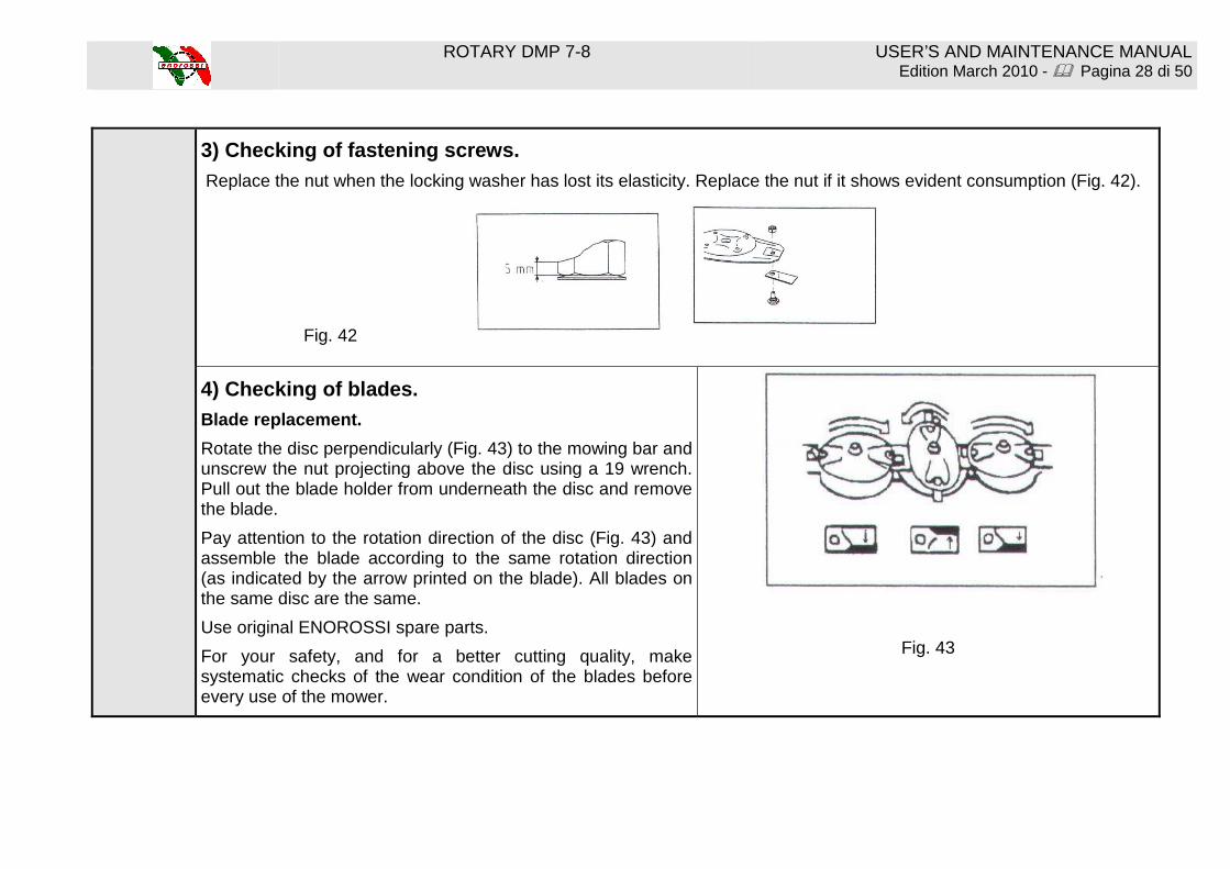
3) Checking of fastening screws.
Replace the nut when the locking washer has lost its elasticity. Replace the nut if it shows evident consumption (Fig. 42).
Fig. 42
4) Checking of blades. Blade replacement.
Rotate the disc perpendicularly (Fig. 43) to the mowing bar and unscrew the nut projecting above the disc using a 19 wrench. Pull out the blade holder from underneath the disc and remove the blade.
Pay attention to the rotation direction of the disc (Fig. 43) and assemble the blade according to the same rotation direction (as indicated by the arrow printed on the blade). All blades on the same disc are the same.
Use original ENOROSSI spare parts.
For your safety, and for a better cutting quality, make systematic checks of the wear condition of the blades before every use of the mower.
Fig. 43
ROTARY DMP 7-8 USER’S AND MAINTENANCE MANUAL Edition March 2010 - � Pagina 29 di 50
Change blades immediately if they are damaged, because if work is done occasionally in difficult conditions, the risk of accidents increases, the cutting quality decreases, and vibrations may also damage the disc support.
Replace blades immediately when they are worn down. Blades should be at least 90 mm long (A) and 30 mm wide (B) (Fig. 44).
Replace the blade if the hole has become ovalized to more than 4 mm (L) (Fig. 44).
IMPORTANT!! Make regular checks of the tightness of all fastening screws and nuts, in particular those that hold blades and discs.
Fig. 44
ROTARY DMP 7-8 USER’S AND MAINTENANCE MANUAL Edition March 2010 - � Pagina 30 di 50
5) Checking of belts (tension adjustment).
To prevent belt slippage, it is necessary to periodically check the belt tension.
To increase tension, tighten nut A on the threaded bar (Fig. 45).
It is very important for the belt tension to be checked after the first hours of work, and later with weekly checks.
Fig. 45
6) Adjustment of the compensating spring. The spring tension is regulated in the factory; the tension may be changed as follows:
Lift the mower until spring B (Fig. 46) is taut. Loosen lock nut C and turn D to reduce or increase tension. After regulating, lock with locknut C.
Fig. 46
ROTARY DMP 7-8 USER’S AND MAINTENANCE MANUAL Edition March 2010 - � Pagina 31 di 50
Section 11 - Lubrication
Lubrication of the mowing bar. Oil level check.
Check the oil level before starting to mow for the first time, and in normal conditions (no oil leaks) every year.
1) To check the oil level, set the mowing bar horizontally (in working position).
2) Lift the bar using the hydraulic hitch as indicated in Fig. 47.
Mod. D3L: Lift the mowing bar 90° and the filling c ap functions as an oil level. Fig. 47
Mod. D4L: B = 40 cm (Fig. 47).
Mod. D5L: B = 125 cm (Fig. 47).
Mod. D6L: B = 30 cm (Fig. 47).
Mod. D7L: B = 35 cm (Fig. 47).
Mod. D8L: B = 50 cm (Fig. 47).
3) Leave the machine still in this position for 15 minutes, to allow the oil to return into the lower part of the mowing bar.
4) Remove the filling cap and check if the oil reaches the hole (Fig. 48).
5) The oil level is correct when the oil reaches the hole of the filling cap.
ROTARY DMP 7-8 USER’S AND MAINTENANCE MANUAL Edition March 2010 - � Pagina 32 di 50
Position of the filling cap.
Mod. D3L-D4L-D5L: between the gear case and the first disc (Fig. 48).
Mod. D5L-D6L-D7L: between the first and second disc (Fig. 48).
Mod. D8L: between the second and third disc.
Fig. 48
Oil replacement.
The oil must be replaced completely after the first 50 hours of work, or at least after 100 hectares mowed.
Lift the mowing bar to a vertical position (Fig. 49). Remove the drainage cap situated at the bottom of the mowing bar and let the oil flow out, taking care to collect and dispose of it in accordance with the waste disposal laws and provisions in force.
Fig. 49
ROTARY DMP 7-8 USER’S AND MAINTENANCE MANUAL Edition March 2010 - � Pagina 33 di 50
Oil replacement must be carried out using hot oil (check that it is not
too hot, in order to prevent burns), since in this case the oil is more fluid and flows out more rapidly, preventing the old, much denser oil remaining inside the bar.
Fill through the filling cap situated on the upper part of the mowing bar.
Use type SAE 80W90 oil.
Oil quantity:
D3L: 1.5 litres
D4L: 2 litres
D5L: 2.5 litres
D6L: 3 litres
D7L: 3.5 litres
D8L: 4 litres
NOTE: During work, it is normal for the oil in the tank and the gear case to heat up; there are no problems if the discs turn freely when turned by hand.
Gear case: Check the level of the gear case oil, with the mower lying horizontal on the ground. Remove the cap with the rod from the upper part of the case (Fig. 50) and check the level of the SAE80W90 type oil.
Cardan shaft lubrication: Grease the cardan shaft and follow the safety instructions supplied by the manufacturer.
ATTENTION! The operator must maintain the protection in conditions of maximum efficiency. Do not approac h the cardan shaft while it is moving.
Fig. 50
ROTARY DMP 7-8 USER’S AND MAINTENANCE MANUAL Edition March 2010 - � Pagina 34 di 50
ROTARY DMP 7-8 USER’S AND MAINTENANCE MANUAL Edition March 2010 - � Pagina 35 di 50
Section 12 – Requesting spare parts
HOW TO CONTACT ENOAGRICOLA ROSSI The ENOAGRICOLA ROSSI customer help and spare parts service is at your disposal. To order spare parts, photocopy this page, fill it out with the requested information, and send it by mail or fax to: