78
PNNL-19129 Prepared for the U.S. Department of Energy under Contract DE-AC05-76RL01830 Discrete Sampling Test Plan for the 200-BP-5 Operable Unit MD Sweeney February 2010

PNNL-19129
Prepared for the U.S. Department of Energy under Contract DE-AC05-76RL01830
Discrete Sampling Test Plan for the 200-BP-5 Operable Unit MD Sweeney February 2010


PNNL-19129
Discrete Sampling Test Plan for the 200-BP-5 Operable Unit MD Sweeney February 2010 Prepared for CH2M HILL Plateau Remediation Company and the U.S. Department of Energy under Contract DE-AC05-76RL01830 Pacific Northwest National Laboratory Richland, Washington 99352


iii
Abstract
The Discrete Groundwater Sampling Project is conducted by the Pacific Northwest National Laboratory (PNNL) on behalf of CH2M HILL Plateau Remediation Company. The project is focused on delivering groundwater samples from selected horizons within select groundwater wells residing in the 200-BP-5 Operable Unit (200-BP-5 OU) on the Hanford Site. This document provides the scope, schedule, methodology, and other details of the PNNL discrete sampling effort.


v
Contents
Abstract ................................................................................................................................................. iii 1.0 Introduction .................................................................................................................................. 1
2.0 Spyder Sampler Description ......................................................................................................... 1
3.0 Well Sampling .............................................................................................................................. 3
3.1 Well and Constitutent List .................................................................................................... 3
3.2 Schedule ............................................................................................................................... 3
3.3 Sampling .............................................................................................................................. 3
4.0 Waste Management ...................................................................................................................... 10
5.0 Quality Sampling .......................................................................................................................... 10
5.1 Equipment Blanks ................................................................................................................ 10
5.2 Duplicate Samples ................................................................................................................ 10
6.0 Reference ...................................................................................................................................... 10
Appendix A – Soil and Groundwater Remediation Project Operating Procedure GRP–FS–04–G–004: Operational Monitoring Groundwater Sampling ...................... A.1
Appendix B – Groundwater Well Construction Documentation .......................................................... B.1

vi
Figures
1 Sampling Head with Silicone Tubing Extending Outward Radially from Central Siphon .......... 22 Modified Spyder Sampler with Drop Tube Assembly .................................................................. 23 Well Location Map ....................................................................................................................... 74 Sampling Schedule ....................................................................................................................... 85 Spyder Sampler Attached to the Bottom of a QED 1250 Bladder Pump ..................................... 9
Tables
1 Depth-Discrete Sample Locations, Intervals, and Constituent Requirements .............................. 42 Constituent List with Sample Volumes ........................................................................................ 7

1
1.0 Introduction
The Discrete Groundwater Sampling Project conducted by the Pacific Northwest National Laboratory (PNNL) on behalf of CH2M HILL Plateau Remediation Company (CHPRC) is focused on delivering groundwater samples from selected horizons within select groundwater wells residing in the 200-BP-5 Groundwater Operable Unit (200-BP-5 OU). The data obtained from these samples are expected to provide information for the Remedial Investigation/Feasibility Study (RI/FS) Work Plan (DOE/RL-2007-18 Rev 1.0) for the 200-BP-5 OU.
PNNL has adapted the Spyder sampler to obtain groundwater samples from discrete horizons within groundwater monitoring wells with the intent of capturing vertical contamination profiles within surrounding hydrologic units. The ability of the system to deliver samples from depth with low-flow and minimal disruption to the groundwater flow regime was tested in several deployments, including the SX tank farm in 1999 (Johnson and Chou 2001).
2.0 Spyder Sampler Description
The PNNL-developed Spyder sampling accessory is added to a pump intake to increase the percentage and volume of water obtained from the formation and filter pack while diminishing the vertical and well-bore contribution to the sample. It is a valuable tool if stagnant water is in portions of the well and if flow is predominantly horizontal through the well. In addition, the volumetric flux (the volume of water moving through the well per unit of time for a specific thickness) is used to determine the allowable extraction rate. Large vertical components may limit or preclude its effectiveness.
The Spyder device consists of a head with flexible tubing extending from the central collector (Figure 1). Angled cuts on the tube ends allow a seal against the well screen when the unit is lowered into place. The hydrodynamic shape minimizes disturbance to the well water and associated primary flow zones and patterns. Water enters primarily from the filter pack and the formation.
The Spyder sampler is coupled to a bladder pump for low-flow (20 to 30 mL/min) sampling. The inlet device consists of a radial array of 12 flexible, small-bore (1/16-in.) silicone tubes attached to the inlet port of a bladder pump with a centralizer. The silicone tubes make contact with the interior wall of the well screen. Nominally 1 L of water is removed to flush the sample line prior to sample collection. The low pumping rate and inlet configuration are designed to minimize vertical disturbance of the aquifer during sample withdrawal so that a discrete depth sample is obtained. The bladder pump allows larger sample volumes to be obtained if required for certain analytical procedures. A minimum water level of 18 in. is required to fully cover the bladder pump before water can be driven from depth to the surface.
The weight of the water column deeper than 285 ft below ground surface (bgs) is greater than the pressure limits of pump controller and bladder pump (125 psi for the currently deployed system). A modified Spyder sampling arrangement (Figure 2) for achieving depths in excess of 285 ft bgs requires the use of chlorinated polyvinyl chloride (CPVC) pipe extensions up to 25 in. in length mounted on the intake end of the bladder pump. The drop tube method has been used to achieve groundwater depths in excess of 500 ft bgs.

2
Figure 1. Sampling Head with Silicone Tubing Extending Outward Radially from Central Siphon
Figure 2. Modified Spyder Sampler with Drop Tube Assembly

3
3.0 Well Sampling
The Spyder sampler will be used to sample discrete horizons within 14 active groundwater monitoring wells in the 200-BP-5 groundwater OU. Table 1 lists the wells to be sampled for this project, as well as the analytes and horizons selected for each well. The schedule for sampling each well is provided in Figure 2. The schedule provided is tentative due to cold-weather considerations.
3.1 Well and Constitutent List
Most of the wells to be sampled are located on the Central Plateau of the Hanford Site; two wells are located in the channel between Gable Mountain and the Central Plateau (Figure 3). All wells reside within the 200-BP-5 OU. The constituents are based on regularly observed elevated radionuclide and nitrate concentrations within these wells. Groundwater field parameters are also part of this list and include pH, specific conductance, temperature, and turbidity. The volume of groundwater required for each analyte is included in Table 2.
3.2 Schedule
The schedule provided in Figure 4 indicates how PNNL staff plan to sample all of the horizons listed in Table 1 in the allotted time. The schedule displayed contains no regard for problems in sampling due to cold weather. The tubing used to deliver the samples from depth to the ground surface and ultimately into the prepared sample container is narrow enough that temperatures below 0°C could hinder sampling for either the early morning hours or perhaps for an entire day. Rescheduling sampling will be coordinated between the CHPRC technical point of contact and the PNNL manager for the Discrete Groundwater Sampling Project, or their respective delegates.
3.3 Sampling
The influence of the type of extraction method, the point of extraction relative to preferential flow zone(s), the rate of extraction, the volume extracted, and the point of discharge (i.e., sampling collection point) are key to knowing where the water came from and what it actually represents relative to the open interval. Once the flow conditions within the well are known, the concentration distribution in the well can be evaluated through discrete interval sampling and, where necessary, time–series sampling. Conventional groundwater sample collection from monitoring wells usually requires two steps or cycles. The first is purging, followed by the second step—sampling.
Well purging is the removal of a desired amount of groundwater before samples are collected for laboratory analysis. The purpose of purging is to ensure that the water samples obtained are representative of the chemical concentrations in the surrounding aquifer. The importance and necessity for well purging to obtain representative samples or measurements is based on the assumption that water quality in the screened interval of the monitoring well– is not representative of that in the immediate surrounding formation.

4
Table 1. Depth-Discrete Sample Locations, Intervals, and Constituent Requirements
Well Name
Constituents(a)
Groundwater Depth (ft bgs)
Screen Interval
(ft bgs)
Sediment Description
(ft bgs)
Discrete Sample Interval (ft bgs)
Discrete Sample Interval (m bgs)
699-50-56 T, N, CN, H-3 152.1 151.2–161.2 151.5–155 gravelly silty sand 153 46.6
155–160 sandy gravel 158 48.2 160–161 silty sandy gravel 161 49.1 161 basalt
699-53-55C T, N, CN, H-3, S 179.1 199.6–220.5 190–205 sand, silt, and gravel 199.6 60.8 205–210 silt, sand, and gravel 209 63.7 210–213 coarse sand and gravel 212 64.6 213–215 fine silt 214 65.2 215–220.5 large gravel, cobble to 5 in. 220 67.1
299–E33–342 U, T, N, CN, H–3, S 235.8 232.6–242.6 230–236 sandy gravel
236–240 gravelly silty sand 236.5 72.1 236–240 gravelly silty sand 239.5 73.0 240–242.4 silty sandy gravel 242.4 73.9
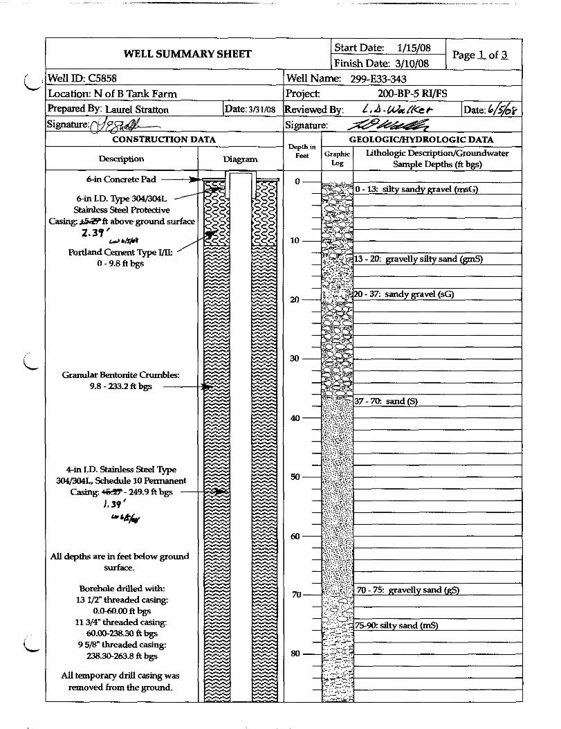
299–E33–343 U, T, N, CN, H–3, S 252.14 249.9–259.9 241–256 gravelly sand 253 77.1
241–256 gravelly sand 255.5 77.9 256–260.9 silty sandy gravel 257.5 78.5 256–260.9 silty sandy gravel 260.7 79.5 260.9 basalt
299–E33–345 U, T, N, CN, H–3, S 253.38 249.7–259.7 250–255 gravelly silty sand 254 77.4
255–260 sandy gravel 256 78.0 260–260.3 gravel 260.1 79.3 260.3 basalt
299–E33–339 T, N, H–3 263.4 259.4–279.3 260–275 sandy gravel 265 80.8
260–275 sandy gravel 270 82.3 260–275 sandy gravel 275 83.8
275–279 silty gravel 278.5 84.9

5
Well Name
Constituents(a)
Groundwater Depth (ft bgs)
Screen Interval
(ft bgs)
Sediment Description
(ft bgs)
Discrete Sample Interval (ft bgs)
Discrete Sample Interval (m bgs)
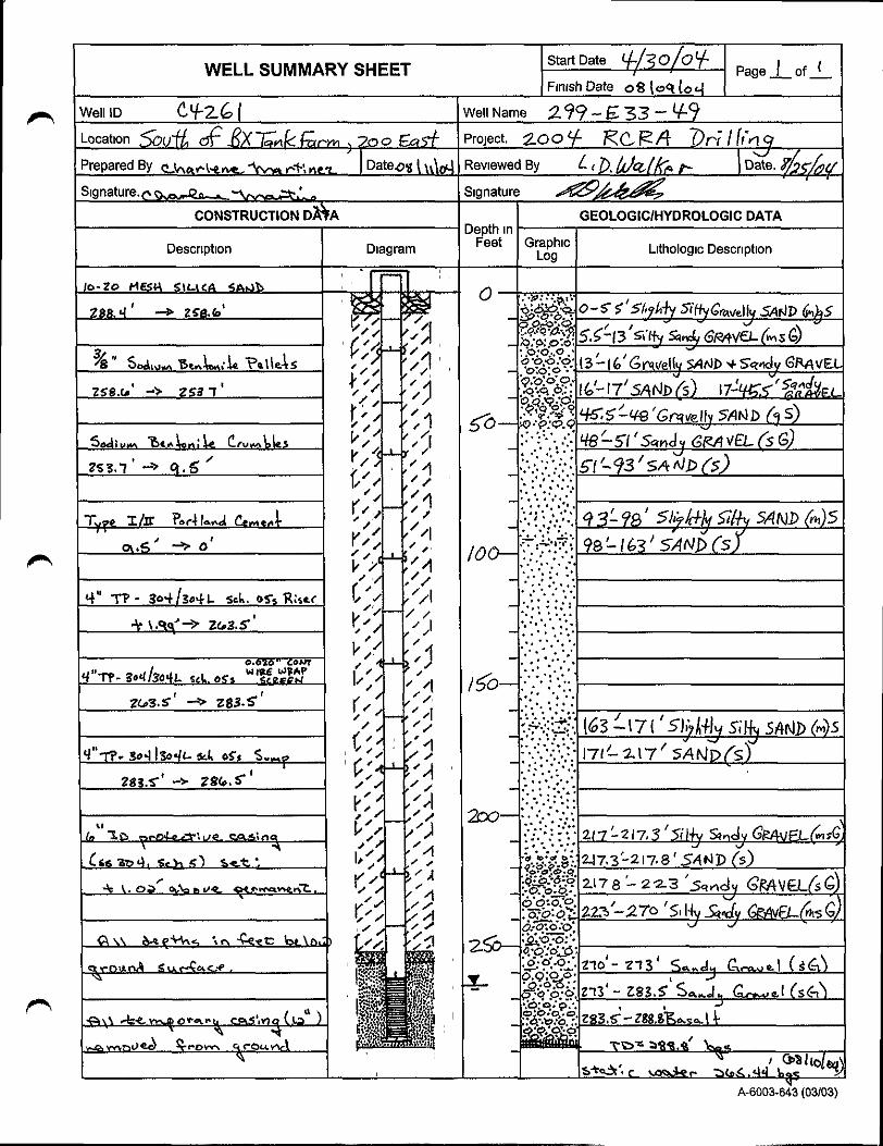
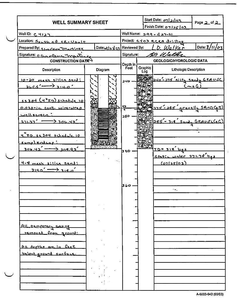
279 basalt 299–E33–49 T, N, H–3 266.5 263.5–283.5 223–270 silty sandy gravel 265 80.8 270–283.5 sandy gravel 270 82.3 270–83.5 sandy gravel 276.5 84.3 270–283.5 sandy gravel 283.2 86.3 283.5 basalt 299–E33–39 T, N, CN, H–3, S 223.8 208–229.2 190–229.0 silty sandy gravel 224.5 68.4 229.0–229.5 sand 229.25 69.9 229.5 basalt 299–E33–31 U, T, N, CN, H–3, S, Cl 247.5 235–255 220–255.6 sandy gravel 250.5 76.4 220–255.6 sandy gravel 255.5 77.9 255.6 basalt 299–E27–23 T, N, H–3, S 274.6 273.5–308.5 260–318 sandy gravel 276 84.1 260–318 sandy gravel 287 87.5 260–318 sandy gravel 297.5 90.7 260–318 sandy gravel 308 93.9 299–E27–4 T, N, H–3, S 272.3 270.3–305.3 255–272 gravel 272–311 sandy gravel 287 87.5 272–311 sandy gravel 297.5 90.7 272–311 sandy gravel 308 93.9 299–E27–7 T, N, H–3, S, Cl 237 241– 281 235–250 fine sand and gravel 242.5 73.9 235–250 fine sand and gravel 249.5 76.0 250–260 gravel, fine sand Ringold FM 255 77.7 260–275 fine sand, gravel Ringold FM 265 80.8 250–260 gravel, fine sand Ringold FM 275 83.8 275–280 Ringold FM 299–E27–21 T, N, H–3, S, Cl 273 271.4–306.4 275–285 gravelly sand 275 83.8 275–285 gravelly sand 285 86.9 285–318 sandy gravel 295 89.9 285–318 sandy gravel 305 93.0 299–E27–10 T, N, S, Cl 225 212.1–232.4 220–230 silty sandy gravel 227 69.2
230–233 sand 232.2 70.8

6
Well Name
Constituents(a)
Groundwater Depth (ft bgs)
Screen Interval
(ft bgs)
Sediment Description
(ft bgs)
Discrete Sample Interval (ft bgs)
Discrete Sample Interval (m bgs)
233–240 sandy gravel 240 basalt
Total No. Samples 48 Total No. Wells 14 (a) Equipment blank highlighted in cyan; duplicate sample highlighted in yellow. U = uranium, CN = cyanide, N = nitrate, S = sulfate, H–3 = tritium, T = technetium–99, Cl = chloride.

7
Table 2. Constituent List with Sample Volumes Analyte Sample Volume Preservation
Technetium–99 300 mL HCl to pH <2
Nitrate 125 mLa Cool ~4oC
Cyanide 250 mL. Cool ~4oC
Uranium 300 mL HNO3 to pH <2
Tritium 500 mL None
Sulfate 125 mLa Cool ~4oC
Chloride 125 mLa Cool ~4oC
(a) Nitrate, chloride, and sulfate all can be sampled from the same IC bottle – 125mL.
Figure 3. Well Location Map

Figure 4. Sampling Schedule
8

9
After the Spyder device is connected to the sampling port of the bladder pump as described in Section 2, the pump assemblage is lowered into the open borehole to the required depth in the aquifer (see Figure 5). Prior to the actual pumping event, sufficient time will be allowed to let disturbances in flow due to insertion into the water column to dissipate. The pump will be operated at flows lower than 300 mL/min, which will slowly raise the water column in the pump tubing to the surface.
Figure 5. Spyder Sampler Attached to the Bottom of a QED 1250 Bladder Pump
The groundwater analytes to be sampled are outlined in Table 1, Section 3.1. Bottles will have been prepared (labeled and recorded in the chain–of–custody record for each well) for each well prior to sampling. The Spyder sampler pump will be started by slowly adding pressure through the hose assembly to the downhole pump from the compressed gas cylinder at the ground surface above. As the first groundwater arrives, it will be captured in a purge water container for later waste management (Section 4). As the water continues to flow, sampling technicians will obtain groundwater parameter readings to determine when to begin filling the sample containers. Guidance for sampling criteria is given in Appendix A.
As the sample bottles are filled, they will be placed in a storage container for transportation to the assigned laboratory. After the final sample bottle for the scheduled well is filled, the sample inventory will be compared to the data in Table 1 to ensure completeness, after which the samples will be shipped to the laboratory for analysis. Samples will be transported, stored, and delivered to the assigned laboratory per CHPRC procedures GRP–FS–04–G–012, “Sample Packaging and Shipping”; GRP–FS–04–G–016,

10
“Chain of Custody/Sample Analysis Request”; GRP–FS–04–G–020, “Sample Storage Units”; and applicable HASQARD requirements.
Decontamination of the sample tubing will be completed after the last sample bottle is filled. Two PNNL staff members will decontaminate the riser tubing using rinse water brought from PNNL to the well each day of sampling. The sampler head and silicone tubing also will be decontaminated using the same water source. The water will be collected according to recommendations from CHPRC waste management staff. All purge and decontamination water will be released to CHPRC staff at the end of the sampling shift.
4.0 Waste Management
A CHPRC waste management coordinator has been assigned to aid in container selection and waste in the waste retention strategy. Cleaning sampling tubing that is in excess of 60 m will generate approximately 1.5 L of rinsate per well. The entire sampling process will generate approximately 10–15 L of purgewater and rinsate per well. The decontamination process will also generate waste–protective glove wear and a minimum number of disposable towels.
5.0 Quality Sampling
5.1 Equipment Blanks
Equipment blanks will be gathered at the beginning of the first well and before sampling at specific wells highlighted in Table 1 (see footnotes).
5.2 Duplicate Samples
Three duplicate samples will be gathered to provide a basis for evaluating sampling and analysis conditions. The timing is highlighted in Table 1 (see footnotes).
6.0 Reference
Johnson VG and CJ Chou. 2001. RCRA Groundwater Quality Assessment Report for Waste Management Area S–SX (November 1997 through April 2000). PNNL–13441, Pacific Northwest National Laboratory, Richland, Washington.

Appendix A
Soil and Groundwater Remediation Project Operating Procedure GRP–FS–04–G–004:
Operational Monitoring Groundwater Sampling


Page 1 of 24
Soil and Groundwater Remediation Project
Operating Procedure
GRP-FS-04-G-004
Operational Monitoring Groundwater
Sampling
Revision: 1
Change: D
Approval Designator: I, Q, R, W
Instruction Use Level: Reference
Approvals on file.
J. G. Hogan
Technical Authority
T. L. Reining
Field Work Supervisor
S. E. Hamaker
NCO (validator)
A. L. Foster
Safety Manager
R. Cook
Electrical Design Authority
T. E. Rainey
Design Authority
S. D. Landsman
Radiological Control Manager
J. D. Mehrer
Geosciences
M. Vermillion
Waste Management
Thackaberry
EQA
S. F. Conley
Sampling Operations Manager
Release Date: 07/01/2009

S&GRP Operating Procedure
Operational Monitoring Groundwater Sampling
GRP-FS-04-G-004
Rev. 1, Chg. D
Page 2 of 24
»» - - - - - - - - - - - - - - - - - - - - - »» S&GRP ««- - - - - - - - - - - - - - - - - - - - - ««
Table of Contents
1.0 PURPOSE AND SCOPE .......................................................................................................3
1.1 Purpose ....................................................................................................................... 3
1.2 Scope ........................................................................................................................... 3
2.0 PRECAUTIONS AND LIMITATIONS ................................................................................3
3.0 SPECIAL TOOLS, EQUIPMENT, AND MATERIALS .......................................................4
4.0 PREREQUISITES ..................................................................................................................4
5.0 INSTRUCTIONS ...................................................................................................................5
5.1 Preparation for Field Sampling ................................................................................... 5
5.2 Sampling Activities .................................................................................................... 6
5.3 Field Readings ............................................................................................................ 7
5.4 Post Sampling Activities ............................................................................................. 9
5.5 Waste Management ................................................................................................... 10
6.0 RECORDS ...........................................................................................................................10
7.0 BIBLIOGRAPHY ................................................................................................................11
8.0 CHANGE SUMMARY ........................................................................................................12
9.0 ATTACHMENTS ................................................................................................................13
Attachment 1 - Sample Collection Using the Submersible Pump....................................... 14
Attachment 2 - Sample Collection Using Hydro Star Pump ............................................... 15
Attachment 3 - Sample Collecting Using Grundfos Redi-FLO 2 Sample Pumps .............. 16
Attachment 4 - Grab Sample Collection (i.e. Bailer, Kabis, weighted bottle) .................... 18
Attachment 5 - Sample Collection from a Piezometer Using the Air Lift Method ............. 19
Attachment 6 - Solinst Discrete Interval Sampler ............................................................... 20
Attachment 7 - Sample Collection Using a Peristaltic Pump .............................................. 22
Attachment 8 - Extraction (Pump and Treat) Well Sample Collection ............................... 23
Attachment 9 - Purge Flow Diagram ................................................................................... 24

S&GRP Operating Procedure
Operational Monitoring Groundwater Sampling
GRP-FS-04-G-004
Rev. 1, Chg. D
Page 3 of 24
»» - - - - - - - - - - - - - - - - - - - - - »» S&GRP ««- - - - - - - - - - - - - - - - - - - - - ««
1.0 PURPOSE AND SCOPE
1.1 Purpose
This procedure provides general requirements and guidance for performing groundwater
sampling by Groundwater Operations (GWO) groundwater monitoring personnel.
1.2 Scope
This procedure is limited to technical sampling activities in which groundwater samples are
collected for field or laboratory analyses.
2.0 PRECAUTIONS AND LIMITATIONS
2.1 All personnel will be familiar with and comply with site-specific safety requirements for
access control.
2.2 If abnormal conditions are encountered call the Field Work Supervisor (FWS).
2.3 Do not sample downwind from sources of volatile organics (e.g., car or generator exhausts,
open fuel tanks), these could potentially contaminate the sample. If such sources are
unavoidable, record them in the logbook and Groundwater Sampling Report (GSR), site
form A-6003-667.
2.4 Avoid direct contact with groundwater except with gloved hands (i.e., surgeons or similar
type gloves).

S&GRP Operating Procedure
Operational Monitoring Groundwater Sampling
GRP-FS-04-G-004
Rev. 1, Chg. D
Page 4 of 24
»» - - - - - - - - - - - - - - - - - - - - - »» S&GRP ««- - - - - - - - - - - - - - - - - - - - - ««
3.0 SPECIAL TOOLS, EQUIPMENT, AND MATERIALS
Using skill-of-the-craft and training, stock the sample vehicle with tools and equipment
required to perform this procedure, including but not limited to the following:
3.1 Decontaminated sampling manifolds (1 per well)
3.2 Disposable 0.45 µm filters
3.3 Peristaltic pump
3.4 Air compressor and generator
3.5 Hydro Star pneumatic cylinder
3.6 Required Instruments
3.7 E-tape (water level measurement device)
3.8 High purity water
3.9 Field logbook
3.10 Groundwater Sampling Report (GSR), site form A-6003-667
3.11 Appropriate PPE
4.0 PREREQUISITES
4.1 Personnel using this procedure must be certified or under the direct supervision of a
certified person to perform this procedure.
4.2 Sampling equipment shall be cleaned prior to use, in accordance with GRP-FS-04-G-013,
Laboratory Cleaning of Sampling Equipment.
4.3 Sample containers used for chemical analysis shall be drawn from controlled storage area
to ensure certified clean prior to use.
4.4 Review AJHA.
4.5 Review applicable MSDS.
4.6 Before initiating any field sampling activities, meet with all field sampling personnel and
review all safety precautions and radiation, health, safety monitoring requirements, and
QA/QC requirements (i.e. Trip Blank, FXR).
4.7 Review the most current "S&GRP Well Waste Spreadsheet" as provided by the FWS to
locate the well number(s) identified to be sampled in an operable unit prior to sampling.
4.8 Review the Groundwater Sample Report; GRP-FS-04-G-016, Chain of Custody/Sample
Analysis Request; and other potential information such as notes, special directions, or
point-of-contacts.
4.9 Check out instruments from storage (i.e., pH, conductivity, etc.) in accordance with GRP-
FS-04-G-005, Control of Monitoring Instruments.

S&GRP Operating Procedure
Operational Monitoring Groundwater Sampling
GRP-FS-04-G-004
Rev. 1, Chg. D
Page 5 of 24
»» - - - - - - - - - - - - - - - - - - - - - »» S&GRP ««- - - - - - - - - - - - - - - - - - - - - ««
5.0 INSTRUCTIONS
5.1 Preparation for Field Sampling
5.1.1 Field Work Supervisor:
a. REVIEW sampling documents (e.g. COCs, sample labels, SAF, sampling
matrix, Groundwater Sampling Report (GSR)) and any other project
information that will provide direction for or assistance with meeting project
requirements.
b. ASSIGN sampling paperwork and sampling task preparation to sampling
personnel.
c. SCHEDULE sampling personnel to support the sampling event(s).
5.1.2 Nuclear Chemical Operator:
• REVIEW sampling documents including COCs, GSR, and sample labels for
sampling event(s).
• ENSURE that appropriate sample containers are prepared and staged for
sampling to be performed.
• IF there is a conflict between any sampling documents regarding container type
or size,
THEN CONTACT the FWS.
• STAGE AND ASSEMBLE equipment required for sampling and field data
collection (label bottles, preservatives, coolers, ice, etc.).
• READ AND BECOME FAMILIAR with applicable project specific safety
documents (i.e. HASP, AJHA, JSA, etc.).
• CONTACT appropriate person in charge of sample site (i.e. BTR, Facility
Manager, FWS, PIC).
• INITIATE field logbook/Data Forms entry including: day, date and time task
started, weather conditions and names and titles and organizations of personnel
performing the task.
• ENSURE initial performance checks of field instruments are complete and
recorded in field logbook.

S&GRP Operating Procedure
Operational Monitoring Groundwater Sampling
GRP-FS-04-G-004
Rev. 1, Chg. D
Page 6 of 24
»» - - - - - - - - - - - - - - - - - - - - - »» S&GRP ««- - - - - - - - - - - - - - - - - - - - - ««
Note
If possible, park adjacent to the well at a right angle to the wind with rear of van facing the well
head.
5.2 Sampling Activities
• PARK vehicle near well for safe operation of sampling equipment.
• ESTABLISH a control area around well.
• MONITOR and CONTROL area around wells as necessary to protect personnel
from injury and prevent damage to equipment.
• Verbally COMMUNICATE or physically ESTABLISH control area using caution
tape or equally effective means.
• VERIFY that the documentation (i.e. GSR) matches the well name.
• DETERMINE appropriate sampling method.
• DON appropriate PPE per task, as needed.
• RECORD instrument pre-check for pH and conductivity on the GSR.
• RECORD lot numbers of sample containers on GSR and/or in field logbook.
• MEASURE depth to water from the designated measurement point,
AND RECORD measurement, to nearest 1 mm, on GSR and/or field logbook, and
Groundwater Measurement form.
• CHECK for a sheen or oil product while cleaning tape.
• IF sheen or oil product is present,
THEN RECORD information on GSR or in field logbook.
5.2.1 INITIATE sampling method and set-up using applicable attachment.
Note
Purge volumes are usually based on pumping 3 borehole volumes of water from the well. The
customer may direct a specific purge volume.
5.2.2 CALCULATE purge time (if not provided by customer) as follows:
a. DETERMINE the flow rate.

S&GRP Operating Procedure
Operational Monitoring Groundwater Sampling
GRP-FS-04-G-004
Rev. 1, Chg. D
Page 7 of 24
»» - - - - - - - - - - - - - - - - - - - - - »» S&GRP ««- - - - - - - - - - - - - - - - - - - - - ««
b. DIVIDE purge volume given for that well by flow rate.
5.2.3 RECORD purge time (in minutes) on GSR and/or in field logbook.
5.2.4 IF the well pumps dry,
THEN TURN off the pump,
AND PERFORM the following:
a. TRACK recharge rate for 15 minutes.
b. IF well does not recharge,
THEN contact FWS.
c. IF well has recharged,
THEN TURN pump back on,
AND fill sample containers.
d. IF the well pumps dry during collection of samples,
THEN REPEAT Steps a. through c.
5.3 Field Readings
Note
• The readings shall stabilize prior to sampling and shall be considered “stable” when the
following are met:
- pH - two consecutive measurements agree within 0.2 pH units
- Temperature - two consecutive measurements agree within 0.2oC
- Conductivity - two consecutive measurements agree within 10% of each other
- Turbidity - less than 5 NTUs prior to sampling (or project scientist’s recommendation).
• Dissolved oxygen and oxygen reduction potential are not indicator parameters and are not
required to be stable prior to sample collection.
5.3.1 OBTAIN field readings at least three times (start, middle, and end of designated
purge time),
AND RECORD readings on GSR.
Note
If a well is not purged, one set of field readings is sufficient unless directed otherwise on the
GSR or by the FWS.

S&GRP Operating Procedure
Operational Monitoring Groundwater Sampling
GRP-FS-04-G-004
Rev. 1, Chg. D
Page 8 of 24
»» - - - - - - - - - - - - - - - - - - - - - »» S&GRP ««- - - - - - - - - - - - - - - - - - - - - ««
5.3.2 Before filling sample bottles, ENSURE purge requirements and required field
readings have been met per GSR, Purge Flow Diagram (Attachment 9), or Project
Scientist instruction.
5.3.3 FILL sample containers in the following order unless otherwise specified in the
sampling plan:
a. Unfiltered volatile organics (VOAs)
b. Unfiltered total organic halogens (TOX)
c. Unfiltered total organic carbon (TOC)
d. Unfiltered semi-volatile organics (Semi-VOAs)
e. Other unfiltered glass containers (i.e., other organics)
f. Other unfiltered samples
g. Filtered samples (in the same order as items a. through f.)
5.3.4 IF sampling order is different from that specified above,
THEN RECORD sampling order and justification for order in field logbook and on
GSR.
5.3.5 After filling last sample container,
MEASURE pH, temperature, specific conductivity, and other requested field
measurements,
AND RECORD on GSR.
Note
When removing portable pumps, if necessary request assistance.
5.3.6 CONCLUDE sampling activity,
AND SECURE equipment.
5.3.7 ENSURE the following:
• Evidence tape has been signed, dated, and attached to container lid.
• Each sample label has been completely filled out by sampler.
• Bottles collected match what is listed on COC.
• Preservation requirements are met.
Note
Rinse water is to be handled as discarded water (i.e., purgewater).
5.3.8 RINSE sampling equipment coming in contact with groundwater being placed in
sample containers or entering well (e.g., E-tapes, instrument probes, etc.) with high-
purity water after sampling is completed.
S&GRP Operating Procedure
Operational Monitoring Groundwater Sampling
GRP-FS-04-G-004
Rev. 1, Chg. D
Page 9 of 24
»» - - - - - - - - - - - - - - - - - - - - - »» S&GRP ««- - - - - - - - - - - - - - - - - - - - - ««
5.3.9 ENSURE well cap has been replaced and locked,
AND ENSURE flush mounted wells are bolted down.
5.3.10 IF a well cannot be secured,
THEN immediately NOTIFY FWS.
5.3.11 CONDUCT post-performance checks of pH and conductivity,
AND RECORD on GSR.
5.3.12 REMOVE AND DISCARD PPE and well waste into waste container when
sampling is complete.
5.4 Post Sampling Activities
5.4.1 ENSURE completion of COC/SAR, GSR and field logbook; field logbook to
include:
• Details of equipment failures
• Breakdowns or unusual occurrences related to the sampling activity
• The sampler signature and date at the bottom of each page
5.4.2 REQUEST independent review of COC forms, sample labels, GSR, and logbook
after completion (one over one check).
5.4.3 PLACE samples in a secure location during transportation.
5.4.4 IF sampling additional well,
THEN RETURN to Step 5.2,
OTHERWISE CONTINUE to Step 5.4.5.
5.4.5 ENSURE samples are packaged in accordance with GRP-FS-04-G-012,
Operational Monitoring Sample Packaging and Shipping.
5.4.6 DELIVER sample to shipping personnel or appropriate laboratory for analysis as
soon as possible.
5.4.7 IF sample(s) cannot be delivered the same day (due to time constraints or
radiological laboratory screening,
THEN store samples according to GRP-FS-04-G-020, Sample Storage Units
AND contact FWS.
5.4.8 IF a portable Grundfos pump was used,
THEN perform the following two substeps prior to returning pump to be cleaned:
a. FLUSH with potable water for 5 min with control-box set at approximately
200 Hz to obtain triple-rinse.

S&GRP Operating Procedure
Operational Monitoring Groundwater Sampling
GRP-FS-04-G-004
Rev. 1, Chg. D
Page 10 of 24
»» - - - - - - - - - - - - - - - - - - - - - »» S&GRP ««- - - - - - - - - - - - - - - - - - - - - ««
b. DISPOSE of water into purge truck.
5.5 Waste Management
5.5.1 REFERENCE the "Well Waste Spreadsheet", MATCH the well name with the
Operable Unit (OU) collection point,
THEN deposit the waste at that OU collection point.
5.5.2 PRINT clearly and legibly when labeling waste.
5.5.3 LABEL/MARK the sample waste at a minimum with: well number, operable unit,
date and operator's name.
5.5.4 IF the Well/Seep Name is not listed on the Well Waste Spreadsheet,
THEN DEPOSIT waste at the RCRA Accumulation Area.
6.0 RECORDS
Document Destination Disposition Field Logbooks S&GRP Operations
secretary in charge of
records
Send to RHA as volume warrants
Chain of Custody forms S&GRP Operations
secretary in charge of
records
Deliver to Sample and Data
Management
Groundwater Sample Record
(A-6003-667)
S&GRP Operations
secretary in charge of
records
Deliver to Sample and Data
Management
Water Level Measurement Form S&GRP Operations
secretary in charge of
records
Deliver to Sample and Data
Management

S&GRP Operating Procedure
Operational Monitoring Groundwater Sampling
GRP-FS-04-G-004
Rev. 1, Chg. D
Page 11 of 24
»» - - - - - - - - - - - - - - - - - - - - - »» S&GRP ««- - - - - - - - - - - - - - - - - - - - - ««
7.0 BIBLIOGRAPHY
7.1 DOE/RL-96-68, HASQARD, Hanford Analytical Services Quality Assurance
Requirements Documents
7.2 GRP-FS-04-G-005, Control of Monitoring Instruments
7.3 GRP-FS-04-G-006, Operate HACH 2100P Turbidimeter
7.4 GRP-FS-04-G-010, Operate Oxidation-Reduction Potential (ORP) Probe
7.5 GRP-FS-04-G-012, Operational Monitoring Sample Packaging and Shipping
7.6 GRP-FS-04-G-013, Laboratory Cleaning of Sampling Equipment
7.7 GRP-FS-04-G-014, Measurements of Groundwater Levels
7.8 GRP-FS-04-G-016, Chain of Custody/Sample Analysis Request
7.9 GRP-FS-04-G-020, Sample Storage Units
7.10 GRP-FS-04-G-041, Operate HQ40d/HQ30d Meter for pH, Conductivity, and Dissolved
Oxygen
7.11 HNF-20635, Groundwater Remediation Project Quality Assurance Project Plan
(GRP-QA-001)
7.12 HNF-RD-210, Records Management Program
7.13 HNF-PRO-10863, Notebooks and Logbooks
7.14 OSWER-9950.1, RCRA Ground-water Monitoring Technical Enforcement Guidance
Document (TEGD)
7.15 WAC 173-160, 1998, Minimum Standards for Construction and Maintenance of Wells

S&GRP Operating Procedure
Operational Monitoring Groundwater Sampling
GRP-FS-04-G-004
Rev. 1, Chg. D
Page 12 of 24
»» - - - - - - - - - - - - - - - - - - - - - »» S&GRP ««- - - - - - - - - - - - - - - - - - - - - ««
8.0 CHANGE SUMMARY
Change
Level
Change By/
Document
Date Pages Description
Rev. 1 GC Clark
DPASF
12855
12/15/08 All Major Change (revision) to incorporate input
from NCOs.
AJHA No.: GW-524
Chg. A GC Clark
DCF 15171
01/05/09 6 Minor Technical Change to add the word
“initial” between ENSURE and performance
ino Step 5.1.2, 8th
bullet.
Chg. B GC Clark
DCF 15372
02/24/09 3, 4, 11,
13, 25
Minor Technical Change to:
1) add site form no. to 2.3;
2) add new 3.11;
3) add site form no. to 6.0 RECORDS;
4) delete Attachment 10 in 9.0
ATTACHMENTS and page 25.
No effect on AJHA.
Chg. C JA Newbill
DCFs
15386,
15460,
15471
03/11/09 6, 7, 9,
11, 15,
16, 18,
23
Minor Technical Change to:
1) Step 5.1.2, sixth bullet: change “logbook”
to “logbook/Data Forms”.
2) Change step 5.2, eighth bullet to read “GSR
and/or field logbook”.
3) Change step 5.3.3.e from “Other organics”
to “Other unfiltered glass containers (i.e.,
other organics)”.
4) Section 6.0 Records table:
a) Delete S&GRP Waste Inventory Sheet
and Continuation Page.
b) Add “S&GRP” to Destination entries.
c) Change second, third and fourth
Disposition entries from “Send to RHA
as volume warrants” to “Deliver to
Sample and Data Management”.
5) Last step of attachments 1, 2, 3, and 7:
change section/step 5.2.11 to section/step
5.2.2 (5.2.11 does not exist).
No effect on AJHA.
Chg. D JA Newbill
CPRs
16005,
16006
07/01/09 6, 24 Minor Technical Change to:
1) Section 5.2, second bullet; add sub-bullets.
2) Attachment 9, second diamond (on right);
change “+/- 10%” to “per step 5.3”

S&GRP Operating Procedure
Operational Monitoring Groundwater Sampling
GRP-FS-04-G-004
Rev. 1, Chg. D
Page 13 of 24
»» - - - - - - - - - - - - - - - - - - - - - »» S&GRP ««- - - - - - - - - - - - - - - - - - - - - ««
9.0 ATTACHMENTS
9.1 Attachment 1 - Sample Collection Using the Submersible Pump
9.2 Attachment 2 - Sample Collection Using the Hydro Star Pump
9.3 Attachment 3 - Sample Collection Using Grundfos Redi-Flo 2 Sample Pump
9.4 Attachment 4 - Grab Sample Collection
9.5 Attachment 5 - Sample Collection from a Piezometer Using the Air Lift Method
9.6 Attachment 6 - Sample Collection Using a Solinst Discrete Interval Sampler
9.7 Attachment 7 - Sample Collection Using a Peristaltic Pump
9.8 Attachment 8 - Extraction (Pump and Treat) Well Sample Collection
9.9 Attachment 9 - Purging Flow Diagram

S&GRP Operating Procedure
Operational Monitoring Groundwater Sampling
GRP-FS-04-G-004
Rev. 1, Chg. D
Page 14 of 24
»» - - - - - - - - - - - - - - - - - - - - - »» S&GRP ««- - - - - - - - - - - - - - - - - - - - - ««
Attachment 1 - Sample Collection Using the Submersible Pump
1.0 ATTACH manifold and purge hose to well.
2.0 ENSURE power switch is in OFF position.
3.0 PLUG power cord into power source and at well head.
4.0 START electric generator AND ALLOW it to warm up, if not already running.
Caution
Do not handle power cords once they have been energized.
5.0 TURN power switch ON to begin pumping process.
IF pump does not work properly, as indicated by a lack of air flow out the drop leg or by
generator ‘lug’ down,
THEN TURN the switch off immediately,
AND PERFORM the following:
5.1 WAIT a few seconds, THEN TURN the switch ON,
AND WAIT to see/hear if pump starts.
Note
• This next step is only necessary on older, electric submersible pumps and will not always be
necessary to start the pump.
• Pausing 15 to 30 seconds between switching “on” and “off” allows breaker trip elements to
cool.
5.2 IF the pump does not start,
THEN TURN the power switch ON and OFF a few times,
Allowing 15 to 30 seconds between each cycle,
finally pausing in the ON position if the pump has started.
5.3 IF a breaker trips or a fuse is blown on the generator,
THEN TURN power switch to OFF position,
AND RESET breaker or fuse as needed.
5.4 DISCONTINUE sampling,
RECORD in GSR/logbook,
AND NOTIFY FWS.
6.0 After water begins to flow from outlet, RETURN to Section 5.2.2 for calculating purge
time.

S&GRP Operating Procedure
Operational Monitoring Groundwater Sampling
GRP-FS-04-G-004
Rev. 1, Chg. D
Page 15 of 24
»» - - - - - - - - - - - - - - - - - - - - - »» S&GRP ««- - - - - - - - - - - - - - - - - - - - - ««
Attachment 2 - Sample Collection Using Hydro Star Pump
Note
Pump is to be operated at up to 2 gpm unless otherwise specified.
1.0 ATTACH manifold and purge hose to well.
2.0 ATTACH pneumatic cylinder assembly (Actuator) to well head assembly.
Caution
• Ensure at least 2 holes on the cylinder support overlap with 2 hole on column support. Also,
ensure cylinder rod is fully extended before attaching actuator rod.
• Actuator is top heavy, use caution when handling - request assistance if necessary.
3.0 ATTACH quick connect on air supply hose to unattached end of control valve on
pneumatic cylinder. The input air pressure should not exceed 120 psi.
Note
Air compressor may not start, if air tank is pressurized. Open drain valve to depressurize tank.
4.0 START air compressor.
5.0 TURN on control valve on pneumatic cylinder. The piston will begin to operate.
6.0 ADJUST the stroke rate to obtain no more than 2 gpm using the control valve located on
the top of pneumatic cylinder .
7.0 After water begins to flow from outlet, RETURN to Section 5.2.2 for calculating purge
time.

S&GRP Operating Procedure
Operational Monitoring Groundwater Sampling
GRP-FS-04-G-004
Rev. 1, Chg. D
Page 16 of 24
»» - - - - - - - - - - - - - - - - - - - - - »» S&GRP ««- - - - - - - - - - - - - - - - - - - - - ««
Attachment 3 - Sample Collecting Using Grundfos Redi-FLO 2 Sample Pumps
(Page 1 of 2)
Note
Pump is to be operated at up to 2 gpm unless otherwise specified.
1.0 IF Redi-Flo 2 pump has been permanently installed, THEN GO-TO step 6.0.
2.0 ENSURE that the Portable Redi-Flo 2 pump has decontamination tag attached (signed
and dated). IF no tag, do not use.
3.0 INSTALL portable Redi-Flo 2 pump using one of the following methods:
• FOLLOW GSR recommendations as to how deep the Redi-Flo 2 pump is to be
installed
• LOWER pump to well bottom THEN RAISE pump to approximately 2 feet from well
bottom.
4.0 LATCH reel in place to secure pump at proper depth.
5.0 CONNECT sample manifold to discharge outlet.
Caution
The Redi-Flo 2 control box is not rated for outdoor use; it should be kept in the sample van.
6.0 CONNECT Redi-Flo 2 control box to dedicated electrical source and pump reel (or
electrical connector of permanently installed pump).
7.0 START electric generator AND ALLOW it to warm up, if not already running.
Caution
Do not handle power cords once they have been energized.
8.0 START the Redi-Flo 2 pump,
AND adjust to obtain desired flow rate.
9.0 IF pump does not work properly, as indicated by a lack of air flow out the drop leg
or by generator 'lug' down,
THEN TURN the Redi-Flo 2 control box off immediately,
AND PERFORM the following:

S&GRP Operating Procedure
Operational Monitoring Groundwater Sampling
GRP-FS-04-G-004
Rev. 1, Chg. D
Page 17 of 24
»» - - - - - - - - - - - - - - - - - - - - - »» S&GRP ««- - - - - - - - - - - - - - - - - - - - - ««
Attachment 3 - Sample Collecting Using Grundfos Redi-FLO 2 Sample Pumps
(Page 2 of 2)
9.1 WAIT a few seconds, THEN Start the Redi-Flo 2 pump.
9.2 ADJUST to obtain desired flow rate,
AND WAIT to see/hear if pump starts.
Note
Pausing 15 to 30 seconds between switching "on" and "off" allows breaker trip elements to cool.
9.3 IF the pump does not start,
THEN Start and stop the Redi-Flo 2 pump a few times,
Allowing 15 to 30 seconds between each cycle,
finally pausing in the ON position if the pump has started.
9.4 IF a breaker trips or a fuse is blown on the generator,
THEN TURN power switch to OFF position,
AND RESET breaker or fuse as needed.
9.5 DISCONTINUE sampling.
9.6 RECORD in the GSR and/or logbook.
9.7 NOTIFY FWS.
10.0 IF pump stops,
THEN OBSERVE indicators on digital display,
AND notify FWS.
11.0 After water begins to flow from outlet, RETURN to Section 5.2.2 for calculating purge
time.

S&GRP Operating Procedure
Operational Monitoring Groundwater Sampling
GRP-FS-04-G-004
Rev. 1, Chg. D
Page 18 of 24
»» - - - - - - - - - - - - - - - - - - - - - »» S&GRP ««- - - - - - - - - - - - - - - - - - - - - ««
Attachment 4 - Grab Sample Collection (i.e. Bailer, Kabis, weighted bottle)
Note
Grab samplers are available in several different sizes and constructed from various types of
materials. The project/GSR shall specify the type of sampler prior to initiation of work.
1.0 ENSURE a laboratory cleaned bailer or field decontaminated sampler is used.
2.0 ATTACH a rope or wire to the sampler.
3.0 Slowly LOWER the bailer into the water.
Caution
Never drop the sampler into the well, doing so may cause degassing of volatile organics or
increase turbidity.
4.0 STOP at appropriate depth and allow sampler to fill.
5.0 RAISE the sampler to the surface.
Note
Water should be poured directly from the sampler into the sample container slowly to prevent
trapping any air bubbles (VOA samples).
6.0 AVOID splashing or agitating the water while the sample container is being filled.
7.0 RECORD sample temperature, pH, turbidity, and conductivity (or other measurements, as
requested), on the GSR or in the field logbook.
8.0 RETURN to Step 5.3.3, "Fill sample containers ..."

S&GRP Operating Procedure
Operational Monitoring Groundwater Sampling
GRP-FS-04-G-004
Rev. 1, Chg. D
Page 19 of 24
»» - - - - - - - - - - - - - - - - - - - - - »» S&GRP ««- - - - - - - - - - - - - - - - - - - - - ««
Attachment 5 - Sample Collection from a Piezometer Using the Air Lift Method
Note
Some piezometer tubes are sampled by the airlift method where the sample water is pushed up
and out of the well by compressed air; an ABS tube has been installed in these wells for this
purpose.
1.0 CONNECT airline to main compressor fitting on sample vehicle.
2.0 ENSURE all valves are closed on 3-way valve.
3.0 CONNECT air line to 3-way valve.
4.0 CONNECT 3-way valve to well head fitting.
5.0 CONNECT sample manifold/drop-leg to piezometer tube.
6.0 START compressor.
Note
When adjusting regulator, turning the valve clockwise increases pressure while turning the valve
counter clockwise reduces pressure. A minimum of 100 psi with a maximum of 125 psi is
required to produce water to the surface.
Caution
Due to the pressurizing of the ABS pipe, do not stand over well head.
7.0 SET output on discharge gauge to a minimum of 100 psi.
8.0 OPEN the air supply valve.
9.0 ALLOW piezometer to reach pressure. IF water reaches surface, THEN COLLECT as
part of purge.
10.0 ONCE flow has stopped, CLOSE pressure valve.
11.0 ALLOW piezometer to recharge 3 to 5 minutes.
12.0 REPEAT Steps 8.0 through 11.0 to continue purge as directed by GSR.
13.0 RECORD sample temperature, pH, turbidity, and conductivity (or other measurements, as
requested), on the GSR or in the field logbook.
14.0 COLLECT all sample water in clean secondary container.
15.0 RETURN to Step 5.3.3, "Fill sample containers ..."

S&GRP Operating Procedure
Operational Monitoring Groundwater Sampling
GRP-FS-04-G-004
Rev. 1, Chg. D
Page 20 of 24
»» - - - - - - - - - - - - - - - - - - - - - »» S&GRP ««- - - - - - - - - - - - - - - - - - - - - ««
Attachment 6 - Solinst Discrete Interval Sampler
(Page 1 of 2)
Caution
Correct installation of O-rings and check balls are essential to the operation of the Solinst
Sampler.
1.0 ASSEMBLE sampler, ensuring white colored ball on bottom and opaque ball on top.
2.0 ATTACH sampler to tubing reel,
AND TIGHTEN swagelok 1/4 turn past hand tight.
Note
Samples collected with the Solinst may require the use of a tripod or drill rig (with safety line).
3.0 Using the sample depth listed on GSR, DETERMINE pressure using the following table.
Recommended Operating Pressure
Depth (feet) Pressure (psi) Depth (meters) Pressure (kPa)
25 20 8 148
50 30 15 217
100 50 30 364
200 95 60 660
300 140 90 952
500 225 150 1540
Note: These are practical minimum pressures, and may be exceeded without adverse affect.
4.0 RECORD Operating Pressure on GSR for each sample interval.
5.0 HOLD the sampler vertically to allow the lower check valve to seat.
6.0 REMOVE the valve cap from the valve stem on the face of the tubing reel,
AND ATTACH the hand pump to the valve stem.
7.0 TURN the valve selector to "pressurize",
AND PRESSURIZE (with hand pump) the sampler to the calculated pressure for the
depth being sampled
8.0 RECORD the pressure where indicated on the GSR.

S&GRP Operating Procedure
Operational Monitoring Groundwater Sampling
GRP-FS-04-G-004
Rev. 1, Chg. D
Page 21 of 24
»» - - - - - - - - - - - - - - - - - - - - - »» S&GRP ««- - - - - - - - - - - - - - - - - - - - - ««
Attachment 6 - Solinst Discrete Interval Sampler
(Page 2 of 2)
9.0 DETACH the pump,
AND THEN lower the sampler to the target depth for sampling.
10.0 TURN the valve selector to "vent"
AND WAIT at least 1 minute for sampler to fill.
11.0 TURN the valve selector to "pressurize".
12.0 ATTACH the pump,
AND PRESSURIZE the sampler to calculated pressure for this sampling depth.
13.0 DETACH the pump.
14.0 RECOVER the sampler from the well slowly by pulling the sampler out of the well and
spooling tubing back onto the reel.
15.0 HOLD the sampler upright,
AND TURN the valve selector to "vent" to release the pressure on the system.
16.0 INSERT the sample release device into the bottom end to release water and fill sample
containers,
AND use remaining water to obtain required field readings.
17.0 As required, DISASSEMBLE the sampler AND RINSE all the pieces thoroughly with
deionized water.
18.0 REPEAT process for each sample interval.
19.0 GO TO section 5.3.7.

S&GRP Operating Procedure
Operational Monitoring Groundwater Sampling
GRP-FS-04-G-004
Rev. 1, Chg. D
Page 22 of 24
»» - - - - - - - - - - - - - - - - - - - - - »» S&GRP ««- - - - - - - - - - - - - - - - - - - - - ««
Attachment 7 - Sample Collection Using a Peristaltic Pump
The principal drawback of peristaltic pumps is they require disposable hose, which must be
compatible with the media being sampled. In addition, this sampling method may be difficult for
collecting representative samples of phased or graduated liquids, as the inlet end of the hose must
be raised and lowered into the container at a very uniform rate. In addition, the completion of a
raising or lowering cycle of the inlet end of the hose must coincide with the completion of filling
the sample container.
Procedure for Use
1.0 If needed, PLACE a pump weight on the end of the hose so that the hose does not float on
the liquid surface.
2.0 CONNECT tubing to the pump head.
3.0 PLACE an inlet hose into the liquid or connect to existing sample port,
THEN ACTIVATE the pumping mechanism.
4.0 DRAW the sample through the inlet hose to a sample container.
5.0 DRAIN liquid in the inlet hose back into the container after pumping (a peristaltic pump
can be run in reverse to empty the tubing back into the container).
6.0 GO TO Step 5.2.2.

S&GRP Operating Procedure
Operational Monitoring Groundwater Sampling
GRP-FS-04-G-004
Rev. 1, Chg. D
Page 23 of 24
»» - - - - - - - - - - - - - - - - - - - - - »» S&GRP ««- - - - - - - - - - - - - - - - - - - - - ««
Attachment 8 - Extraction (Pump and Treat) Well Sample Collection
Note
Prior to collecting samples, make sure the extraction (pump and treat) well is up and running or
operations support is available to start the process in order to obtain groundwater samples.
1.0 RECORD valve number.
2.0 RETURN to Section 5.3, "Field Readings".

S&GRP Operating Procedure
Operational Monitoring Groundwater Sampling
GRP-FS-04-G-004
Rev. 1, Chg. D
Page 24 of 24
»» - - - - - - - - - - - - - - - - - - - - - »» S&GRP ««- - - - - - - - - - - - - - - - - - - - - ««
Attachment 9 - Purge Flow Diagram

Appendix B
Groundwater Well Construction Documentation


CONSTRUCllON DATA I Demh I G80LOGiC"Y DROLOGiC DATA I . in
Feet
5 IO
15
20 2s 30 35 40 45 m
I GraohicLoq i Litholooic Descriation

I Oercrirnion i
11{ I I I I I I I 1 1 1 1 1 1 I 1 1 1 1 1 1 1 1 1 1 1 1 1 1 I I I I I I I I I I I I I I I I I I I I I b==d 1 1 1 1 1 1 1 1 1 l 1 1 1 1 I l l 0 0 I I I I I I I 1 1 1 1 f 1 1 I f f 1 1 1 1 I l l f l f l 1 1 1 1 1 l 1 l
I I I I I 1 1 1 1 l ~ I I I I I
.. . Feet -
i i i i i I I I I I I I I I I 1 l 1 1 1 l l l l l f l l l l 1 1 1 1 l I 1 1 1 1 1 l 1 1 1 1 1 1 1 1
I
I 1
I I+ 1 . I
-I I
I\

I
OBatterle h c i f i i Nmlrml Liboratorin
AS- B U I LT DIAGRAM
Construction Data
Description Diagram
Depth in
Feet
c
Geologic/Hydrologic Data
Diagram Litho.
. . . . . . . . . . , .. ,. -i
. . . . -. :. :a: . . _ . ' . . . . . . . D :. . . . . . . :. . . .- ~ i (.., . . . . . . . . . . -. . , .: :-
' . i . . . . . . . . . b .
. . . . . . . . . . . . .
. . " _ . : . . _ :
. . . . . . . . . . . . . . - ._ :A- - .
. . . . :. ,
- - .: ._ - . .. - . . ' . . . . . . ~. . . . . . . . . . . . . . . . . . : . . . .* . :. .. .. .' . . .
. . . , .- - 0 * : i : . . . . *
.-
. . . . . . . . . .
. ,. _"., .. , . . . . .
'; . . . . . . . . . . . . . . . . . . . . . . . . , . . . . . . . . . . . . . . . . . . * . .
. ' . . ' 0 . ,a' -'. .
. . . . . . . . . . . . .
II

I
OBanelle ~nfii ~onhuwu L.baa-
\
AS-BUILT DIAGRAM
_ _ . . - .... -. .
Construction Data Geologic/Hydrologic Data ,- Depth
in Feet
Diagram Litho.
. . . . . . . . . . . . . . . . . . . . . . . . . . . . . . . . . . * . . . . . .
Diagram
. i i _ . . . . . . . . . . , . _ . . - . . . . . . . . . . _ ' ..: - . . . . . . . . . . .. I , ' . . . . . . . . . . . . . . . . . . . . . . . .
0 - . '.e . 0 o..o
. . a".. 0 . . . . . . 0 '.o; ,
' 0 0 , ' ' 0.
UT L z o
Z t S
*- * . 0 . 0 -
0 4 0 - 0 0


c . .
I WELL CONSTRUCTION AND COMPLETION SUMMARY AS-BUILT
GWUUUZED STRATIGRAPHY
0-40: Fine SAND and GRAVEL 400-140: Fine SAND 140-150: fine SAND and GRAVEL 150- 160: SAND and GRAVEL
200-210: Fine SAND and GRAVEL 210-220: GRAVEL and SAND
I I
160-200: Fine W D 1
220-235: SAND and GRAVEL 235-250: Fine SAND and GRAVEL 250-260: GRAVEL, FINE Y W D and Ringold Fm. 260-275: Fine SAND, GRAKl and Ringold fm.
-275-280: Ringold
INF 20.0
lEIf
241.0
N/A I


i
)Battelle AS - BUILT DI AG R A M Pwlfic Noflhwnt labofatorin
.

.:.- .., t '. : . . I
.: . .'/
. . ....
3,m#elle Pacific Northwest Laboratories
AS - B U I LT D I AG R A M
Construction Data
I
. ,
A.lB[X)-186 13/87)
. ~ . . . . . . . . . . . . . . . . . . . . . , . .
. _ . _ _ ..,--;. ;. ,-- ,. . . . . .
. . - Q

PNNL-19129
Distribution
No. of No. of Copies Copies
Distr.1
6 CH2M HILL Plateau Remediation
Company
G. S. Thomas (5) R3–50 C. D. Weittreich H8–15
3 Pacific Northwest National Laboratory S. N. Schlahta K6–83 M. D. Sweeney (2) K6–75


