13
Distillation units for solvents and water- based media Cleaning solutions and solvent recovery. www.dw-renzmann.de

Distillation units for solvents and water- based media
Cleaning solutions and solvent recovery.
www.dw-renzmann.de

2 3
Safety concept
D.W. RENZMANN Apparatebau GmbH
D.W.RENZMANN Apparatebau GmbH has been developing, man-ufacturing and selling cleaning and treatment systems for print shops and for paint and varnish producers for nearly 50 years.
Our core competency is the removal of stubborn residues and the handling of the flammable organic solvents or aggressive alkaline washing agents used for this purpose.
In addition to the design, manufacturing and sale of equipment, we also offer a comprehensive portfolio of services. On request, we will:
perform profitability calculations with regard to performance, staff requirements, and investment and operating costs, taking into account all relevant legislation, regulations and guidelines
create technical documentation for each product
support and implement approval procedures and draw up appli-cations to authorities
connect your new equipment to pre-existing exhaust air or waste water treatment systems
provide worldwide service, including commissioning, assembly, repair and maintenance, through our expert staff
RENZMANN equipment is used all over the world and has gained an international reputation for excellent quality.
Requirements for distillation equipment
RENZMANN develops modern distillation processes and technol-ogies that comply with today’s increasingly restrictive environ-mental and occupational safety regulations and reflect the aim of sustainable environmental protection.
Explosion protection requirements for solvent distil-lation units
The outside of Renzmann solvent distillation units meets the requirements of ATEX category 2; the units may therefore be oper-ated in explosion hazard zone 1. Internal explosion protection
When solvent in a container is heated to a temperature above its flash point, a potentially explosive solvent vapor/air mixture is generated above the liquid level. That is why the inside of contain-ers filled with flammable liquids is classified as zone 0 according to the Technical Guidelines for flammable liquids.
The concept of RENZMANN solvent distillation units
The interior of the units meets the requirements of category 1 devices; the distillation units may therefore be operated with zone 0 on the inside
Electrical and moving mechanical components on the inside are Modele-examined in accordance with ATEX
Explosion protection of the vacuum unit
The vacuum unit extracts the explosive atmosphere above the liquid in the distillation boiler until a vacuum is established, and maintains the vacuum by sucking off air that leaks into the distilla-tion unit from outside. The vacuum pump delivers air if the vacuum must be reduced due to foaming or to prevent cavitation caused by leak air at the suction side of the vacuum pump. This means that the vacuum pump constantly aspirates explosive atmosphere at vapor/air temperatures above the flash point, and the inside of the pump must therefore be classified as zone 0.
D.W. RENZMANN
uses liquid jet vacuum pumps made of metal that are grounded and contain no moving parts; this means the pumps have no potential ignition sources. Consequently, they may be operated with zone 0 on the inside.
The centrifugal pump that primes the jet pumps is always filled with solvent, i.e. it contains no explosive atmosphere; this is monitored redundantly
Renzmann only uses liquid ring vacuum pumps (centrifugal) for solvents with a flash point > 50°C and if the distillate is cooled down to below the flash point in the condenser of the distilla-tion unit (this is monitored). Pumps of this Modele do not meet the requirements of category 1 for low flash points, unless very sophisticated monitoring equipment is used and certain process parameters are observed that are impossible to comply with in the daily running of a distillation unit.
Explosion-proof solvent distillation units are subject to the following legally binding directives:
Machinery Directive 2006/42/EC
ATEX Directive 2014/34/EU (ATEX)
EMC Directive 2014/30/EU (Electromagnetic Compatibility)
For ROTOmaX distillation units: Pressure Equipment Directive 2014/68/EU
Compliance with these directives is documented by means of the CE mark at the machine/unit and a declaration of conformity.
RENZMANN is certified under the German Water Resources Law.
4 5
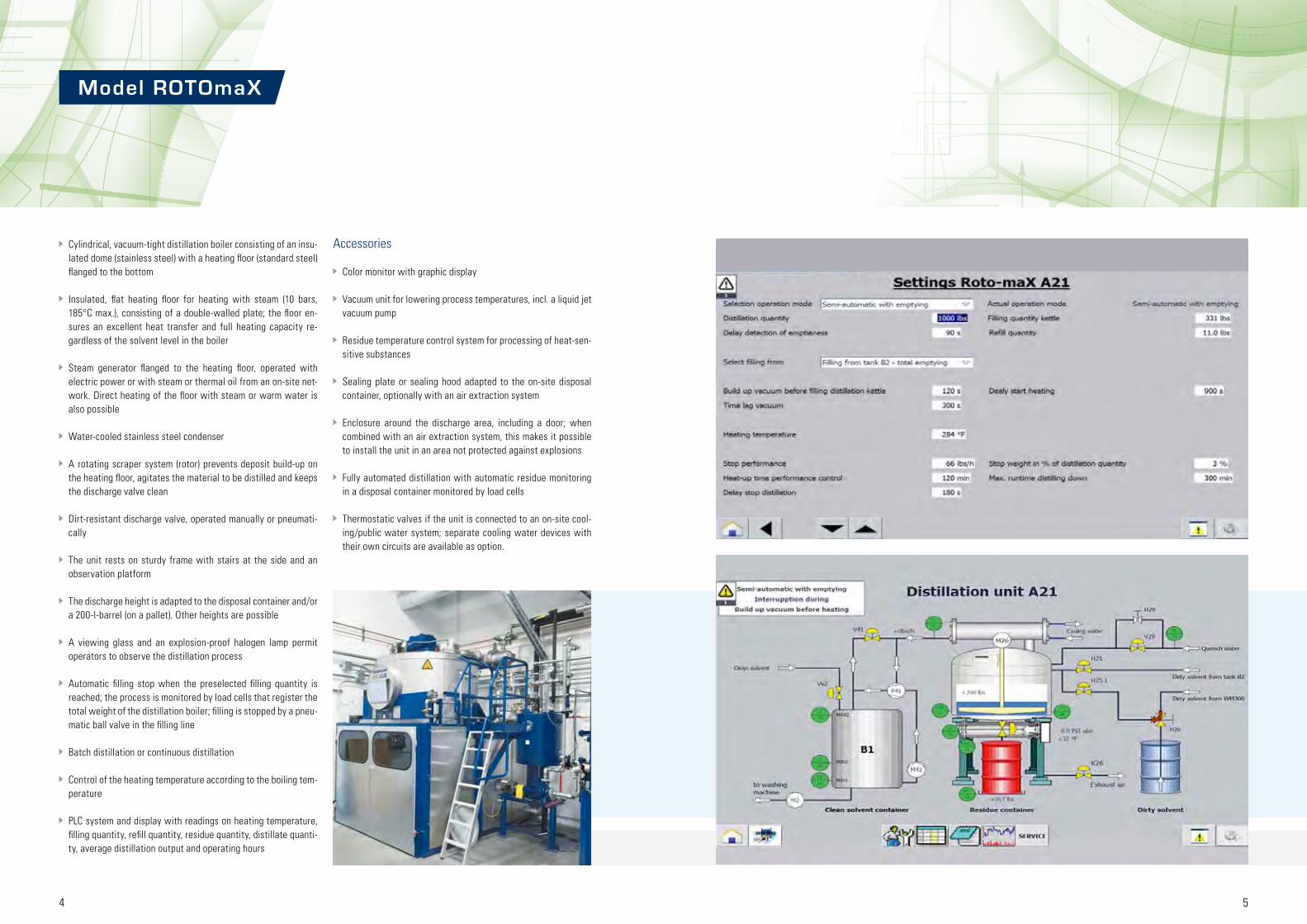
Model ROTOmaX
Cylindrical, vacuum-tight distillation boiler consisting of an insu-lated dome (stainless steel) with a heating floor (standard steel) flanged to the bottom
Insulated, flat heating floor for heating with steam (10 bars, 185°C max.), consisting of a double-walled plate; the floor en-sures an excellent heat transfer and full heating capacity re-gardless of the solvent level in the boiler
Steam generator flanged to the heating floor, operated with electric power or with steam or thermal oil from an on-site net-work. Direct heating of the floor with steam or warm water is also possible
Water-cooled stainless steel condenser
A rotating scraper system (rotor) prevents deposit build-up on the heating floor, agitates the material to be distilled and keeps the discharge valve clean
Dirt-resistant discharge valve, operated manually or pneumati-cally
The unit rests on sturdy frame with stairs at the side and an observation platform
The discharge height is adapted to the disposal container and/or a 200-l-barrel (on a pallet). Other heights are possible
A viewing glass and an explosion-proof halogen lamp permit operators to observe the distillation process
Automatic filling stop when the preselected filling quantity is reached; the process is monitored by load cells that register the total weight of the distillation boiler; filling is stopped by a pneu-matic ball valve in the filling line
Batch distillation or continuous distillation
Control of the heating temperature according to the boiling tem-perature
PLC system and display with readings on heating temperature, filling quantity, refill quantity, residue quantity, distillate quanti-ty, average distillation output and operating hours
Accessories
Color monitor with graphic display
Vacuum unit for lowering process temperatures, incl. a liquid jet vacuum pump
Residue temperature control system for processing of heat-sen-sitive substances
Sealing plate or sealing hood adapted to the on-site disposal container, optionally with an air extraction system
Enclosure around the discharge area, including a door; when combined with an air extraction system, this makes it possible to install the unit in an area not protected against explosions
Fully automated distillation with automatic residue monitoring in a disposal container monitored by load cells
Thermostatic valves if the unit is connected to an on-site cool-ing/public water system; separate cooling water devices with their own circuits are available as option.

6 7
* Subject to technical changes
Distillation unit ROTOmaX 15 ROTOmaX 20 ROTOmaX 30
Capacity l approx. 50 - 250 approx. 50 - 250 approx. 70 - 400
Boiler capacity l approx. 350 approx. 450 approx. 750
Distillation output l/h * approx. 45 - 90 approx. 60 - 120 approx. 90 - 180
Cooling water consumption m3/h ** approx. 1,3 approx. 1,7 approx. 2,5
Heating capacity kW 15 20 30
Weight kg ** 2200 2300 2500
W x H x D W x H x D W x H x D
Dimensions mm *** 1500 x 3100 x 1900 1500 x 3100 x 1900 1700 x 3200 x 2100
Required space mm 4500 x 3400 x 4000 4500 x 3400 x 4000 4500 x 3600 x 4200
Transport clearance mm 1700 x 2200 x 2000 1700 x 2200 x 2000 1800 x 2400 x 2300
Distillation unit ROTOmaX 50 ROTOmaX 75 ROTOmaX110
Capacity l approx. 130 - 650 approx. 200 - 1000 approx. 300 - 1500
Boiler capacity l approx. 1300 approx. 2000 approx. 3000
Distillation output l/h * approx. 150 - 300 approx. 225 - 450 approx. 330 - 660
Cooling water consumption m3/h ** approx. 4,3 approx. 6,3 approx. 9,5
Heating capacity kW 50 75 110
Weight kg ** 2700 3100 3300
W x H x D W x H x D W x H x D
Dimensions mm *** 2000 x 3300 x 2500 2300 x 3500 x 2850 2600 x 3600 x 3150
Required space mm 5000 x 3500 x 4600 5400 x 3700 x 5200 4800 x 3700 x 5500
Transport clearance mm 2100 x 2600 x 2700 2400 x 2850 x 3000 2700 x 2900 x 3300
* Output depends on the solvent
** If water from a public system is used; depends on the water temperature and the boiling point of the solvent; a closed cooling circuit with zero water consumption is possible
*** Standard version without accessories or containers
Model ROTOmaX

8 9
Batch distillation or continuous distillation
Control of the heating temperature according to the boiling tem-perature
PLC system and display with readings on heating temperature, filling quantity, refill quantity, discharge quantity and distillate quantity
Accessories
Vacuum unit for lowering process temperatures, incl. a liquid jet vacuum pump
Residue temperature control system for processing of heat-sen-sitive substances
Sealing plate or sealing hood adapted to the on-site disposal container, optionally with an air extraction system
Thermostatic valves if the unit is connected to an on-site cool-ing/public water system; separate cooling water devices with their own circuits are available as option
Cylindrical, vacuum-tight distillation boiler consisting of an insu-lated dome (stainless steel) with a heating floor (standard steel) flanged to the bottom
Insulated, flat heating floor for heating with steam (10 bars, 185°C max.), consisting of a double-walled plate; the floor en-sures an excellent heat transfer and full heating capacity re-gardless of the solvent level in the boiler
Steam generator flanged to the heating floor, operated with electric power or with steam or thermal oil from an on-site net-work. Direct heating of the floor with steam or warm water is also possible
Water-cooled stainless steel condenser
Rotating scraper system (rotor), prevents deposit build-up on the heating floor, agitates the material to be distilled and keeps the discharge valve clean
Dirt-resistant discharge valve, operated manually or pneumati-cally
The unit rests on a robust frame
The discharge height is adapted to the disposal container and/or a 200-l-barrel (on a pallet). Other heights are possible
A viewing glass and an explosion-proof halogen lamp permit operators to observe the distillation process via mirrors
Automatic filling stop when the preselected filling quantity is reached; the process is monitored by load cells that register the total weight of the distillation boiler; filling is stopped by a pneu-matic ball valve in the filling line
Distillation unit ROTOmaX-e 15 ROTOmaX-e 20 ROTOmaX-e 30
Capacity l approx. 50 - 200 approx. 50 - 250 approx. 70 - 400
Boiler capacity l approx. 350 approx. 450 approx. 750
Distillation output l/h * approx. 45 - 90 approx. 60 - 120 approx. 90 - 180
Cooling water consumption m3/h ** approx. 1,5 approx. 2,0 approx. 2,5
Heating capacity kW 15 20 30
Weight kg *** 2000 2000 2300
W x H x D W x H x D W x H x D
Dimensions mm ** 1500 x 3100 x 1900 1500 x 3100 x 1900 1700 x 3200 x 2100
Required space mm ** 4500 x 3400 x 4000 4500 x 3400 x 4000 4500 x 3400 x 4200
Transport clearance mm ** 1700 x 2200 x 2000 1700 x 2200 x 2000 1800 x 2400 x 2300
* Output depends on the solvent
** If water from a public system is used; depends on the water temperature and the boiling point of the solvent; a closed cooling circuit with zero water consumption is possible
*** Standard version without accessories or solvent containers
* Subject to technical changes
Model ROTOmaX-e
10
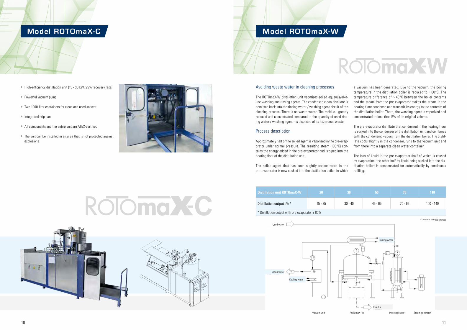
High-efficiency distillation unit (15 - 30 kW, 95% recovery rate)
Powerful vacuum pump
Two 1000-liter-containers for clean and used solvent
Integrated drip pan
All components and the entire unit are ATEX-certified
The unit can be installed in an area that is not protected against explosions
Distillation unit ROTOmaX-W 20 30 50 75 110
Distillation output l/h * 15 - 25 30 - 40 45 - 65 70 - 95 100 - 140
* Distillation output with pre-evaporator + 80%
W
C
11
* Subject to technical changes
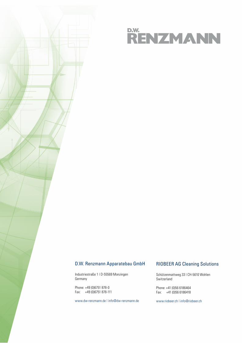
Model ROTOmaX-C Model ROTOmaX-W
Avoiding waste water in cleaning processes
The ROTOmaX-W distillation unit vaporizes soiled aqueous/alka-line washing and rinsing agents. The condensed clean distillate is admitted back into the rinsing water / washing agent circuit of the cleaning process. There is no waste water. The residue - greatly reduced and concentrated compared to the quantity of used rins-ing water / washing agent - is disposed of as hazardous waste.
Process description
Approximately half of the soiled agent is vaporized in the pre-evap-orator under normal pressure. The resulting steam (100°C) con-tains the energy added in the pre-evaporator and is piped into the heating floor of the distillation unit.
The soiled agent that has been slightly concentrated in the pre-evaporator is now sucked into the distillation boiler, in which
a vacuum has been generated. Due to the vacuum, the boiling temperature in the distillation boiler is reduced to < 60°C. The temperature difference of > 40°C between the boiler contents and the steam from the pre-evaporator makes the steam in the heating floor condense and transmit its energy to the contents of the distillation boiler. There, the washing agent is vaporized and concentrated to less than 5% of its original volume.
The pre-evaporator distillate that condensed in the heating floor is sucked into the condenser of the distillation unit and combines with the condensing vapors from the distillation boiler. The distil-late cools slightly in the condenser, runs to the vacuum unit and from there into a separate clean water container.
The loss of liquid in the pre-evaporator (half of which is caused by evaporation, the other half by liquid being sucked into the dis-tillation boiler) is compensated for automatically by continuous refilling.
Used water
Clean water
Cooling water
Residue
Cooling water
Vacuum unit ROTOmaX–W Pre-evaporator Steam generator

12 13
Distillation systems for combined solid-liquid and liquid-liquid separation
+ pa
cked
col
umn Combination
Liquid-liquid separation
Fully automated process under vacuum
Contains structured high-performance packing
Dist
illat
ion
unit
Combination
Solid-liquid separation
Fully automated process
Vacuum unit lowers the operating temperature
Scraper prevents deposit build-up and improvesheat transfer; automatic residue discharge
Load cells monitor the filling quantity
Application example
Distillation of NMP containing binding agents and water: Clean NMP with < 200 ppm residual water content
Customized service
Project planning to adapt the equipment to your requirements:
Distillation tests in our laboratory
Possibility of enclosing the equipment for installation in an area not protected against explosions
13
Model ROTOmaX + packed column
Cooling water
Condenser
Rotating scraper system
Load cells
Dist
illat
ion
boile
r
Resi
due
outle
t
Load cells
Distillate containerUsed agent container
Heating
Residue container

14 15
Accessories
Vacuum unit for lowering process temperatures, with either a liquid ring vacuum pump (for solvents with a flash point > 55 °C) or a liquid jet vacuum pump
Residue temperature control system for processing heat-sensi-tive substances
Distillation output monitor for automatic distillation stop when the output drops below a set limit
Timer for automatic distillation start
Seal plate or exhaust hood adapted to on-site disposal cont-ainer, optionally with an air extraction system
Thermostatic valves if the unit is connected to an on-site coo-ling/ public water supply; separate cooling water devices with separate circuits are available as option
Cylindrical, vacuum-tight stainless steel distillation boiler
Insulated heating jacket; standard version: floor and lower ja-cket surface with integrated electrical heating elements and filled with thermal oil / with heating elements and filled with water (maintenance-free heating, max. heating temperature 130 °C). Alternatives: Connection to an on-site hot water, steam or thermal oil network
Water-cooled stainless steel condenser
A rotating scraper system (rotor) prevents deposit build-up on the heating surfaces and agitates the material to be distilled
Dirt-resistant discharge valve, operated manually or pneumati-cally
The unit rests on sturdy frame with stairs at the side and an observation platform (accessory for ROTO 9)
The discharge height is adapted to the disposal container and/or a 200-l-barrel (on a pallet) (accessory for ROTO 9, standard discharge height 650 mm). Other heights are possible
Optional: adapted residue carriage (only with ROTO 9)
A viewing glass and an explosion-proof halogen lamp permit operators to observe the distillation process
Automatic filling stop by means of a vibration limit switch and a pneumatic ball valve in the filling line
Batch distillation or continuous distillation
Explosion-proof control elements at the distillation unit for va-cuum, filling, heating, rotor rotation and EMERGENCY STOP
Programmable logic controller (PLC) with display for text, input of and/or information on the chronological sequence of the va-cuum, filling, heating and rotor functions and the distilling-off times
Distillation unit ROTO 9 ROTO 12 ROTO 18
Capacity l approx. 140 approx. 250 approx. 400
Boiler capacity l approx. 300 approx. 480 approx. 700
Distillation output l/h * approx. 30 - 60 approx. 40 - 80 approx. 60 - 100
Cooling water consumption m3/h ** approx. 0,7 approx. 1 approx. 1,5
Heating capacity kW 9 12 18
Weight kg *** 1300 2200 2500
W x H x D W x H x D W x H x D
Dimensions mm *** 1500 x 3100 x 1700 1500 x 3400 x 1950 1600 x 3550 x 1950
Required space mm *** 4000 x 3400 x 3000 5000 x 3700 x 4000 5000 x 4000 x 4000
Transport clearance mm *** 1700 x 1700 x 3200 1600 x 2400 x 1900 1800 x 2400 x 2000
* Output depends on the solvent
** If water from a public system is used; depends on the water temperature and the boiling point of the solvent; a closed cooling circuit with zero water consumption is possible
*** Standard version without accessories or solvent containers
* Subject to technical changes
Model ROTO

16 17
Accessories
Vacuum unit
Automatic filling under vacuum
Thermostatic valves if the unit is connected to an on-site coo-ling/public water system; separate cooling water devices with their own circuits are available as option
For distilling washing-out solvents: compact version for installati-on outside the hazard area
Cubical, vacuum-tight distillation boiler, pressure relief valve, sol-vent-resistant coating
Heating jacket with thermal oil as heat transfer medium, integ-rated heating elements (Ex de), oil expansion tank with minimum level switch as safety against a lack of oil
Insulation of boiler and heating jacket
Water-cooled condenser; components in contact with the medi-um are made of stainless steel
A temperature limiter switches off the heating if the selected sol-vent temperature is exceeded
Large cleaning hole with hinged lid and a ball valve for residue discharge
Signal lamp and EMERGENCY STOP, explosion-proof, mounted directly at the distillation unit
Control cabinet with control elements, for installation outside the hazard area
Separate pneumatics control cabinet
Batch distillation
Distillation unit M 200 M 400
Capacity l 225 400
Boiler capacity l approx. 360 approx. 670
Distillation output l/h * 30 - 60 60 - 100
Cooling water consumption m3/h ** approx. 1,5 approx. 2,0
Heating capacity kW 9 18
W x H x D W x H x D
Dimensions mm *** 1850 x 2500 x 1360 2100 x 2570 x 1670
Required space mm *** 3200 x 3200 x 2500 3200 x 3200 x 2500
Transport clearance mm *** 1000 x 1600 x 1700 1800 x 1600 x 2300
* Output depends on the solvent
** If water from a public system is used; depends on the water temperature and the boiling point of the solvent; a closed cooling circuit with zero water consumption is possible
*** For an installation with a vacuum unit
* Subject to technical changes
Model M
Model M

18 19
Accessories
Vacuum unit
Automatic filling under vacuum
Thermostatic valves if the unit is connected to an on-site cool-ing/public water system; separate cooling water devices with their own circuits are available as option
For distilling washing-out solvents: compact version for installa-tion outside the hazard area
Cylindrical, vacuum-tight distillation boiler, pressure relief valve, hinged lid with a pneumatic spring as counterweight, viewing glass and heat- and solvent-resistant gasket
Heating jacket with thermal oil as heat transfer medium, inte-grated heating elements (Ex de), minimum level switch as safety against a lack of oil
Insulation of vessel, heating jacket, and lid
Water-cooled condenser, components in contact with the medium are made of stainless steel
A temperature limiter switches off the heating if the selected solvent temperature is exceeded
Cleaning hole with hinged lid for residue discharge
Signal lamp and EMERGENCY STOP, explosion-proof, mounted directly at the distillation unit
Control cabinet with control elements, for installation outside the hazard area
Separate pneumatics control cabinet
Batch distillation
Distillation unit DW 50 DW 100
Capacity l 50 100
Boiler capacity l approx. 150 approx. 150
Distillation output l/h * 20 - 40 30 - 60
Cooling water consumption m3/h ** approx. 1,5 approx. 2,0
Heating capacity kW 4,5 9
W x H x D W x H x D
Dimensions mm *** 1420 x 2870 x 1850 1420 x 2870 x 1850
Required space mm *** 4000 x 3500 x 3400 4000 x 3500 x 3400
Transport clearance mm *** 1600 x 2400 x 2000 1600 x 2400 x 2000
* Output depends on the solvent
** If water from a public system is used; depends on the water temperature and the boiling point of the solvent; a closed cooling circuit with zero water consumption is possible
*** For an installation with a vacuum unit
* Subject to technical changes
Model DW
Model DW

20 21
A2A1
B4B3B5
Debinding chamber Buffer chamber Solvent container used clean Distillation unit
Solvent
Ventilation
Debinding
B5 Buffer chamber
In the drying phase, the solvent atmosphere from the debinding chamber A1 is pumped into the previously evacuated buffer con-tainer B5 by a vacuum pump. The gaseous hexane is trapped in the condenser and recovered
The evacuation of the debinding chamber A1 leads to the com-plete evaporation of the solvent residues on the workpieces and the inner chamber surfaces. The evaporated solvent is also trapped in the condenser
When the chamber is ventilated with ambient air, the air ab-sorbs a very small quantity of residual solvent, which may be filtered out with an activated carbon filter
Lower boiling temperatures and steam pressures under vacuum mean there are virtually no solvent emissions into the exhaust air, no emissions into the workspace and solvent consumption is min-imal.
A1 Debinding chamber
Once the workpieces (green compacts) have been loaded into the debinding chamber A1, the dry and solvent-free atmosphere of the chamber is evacuated and replaced with the solvent-lad-en atmosphere from buffer container B5
In the debinding phase, heated solvent (hexane) is circulated around the green compacts. Perforated plates at the inlet and outlet sides and the circulation of the solvent work together to create an evenly distributed current
Periphery
A solvent vapor recovery system between all containers pre-vents the hexane from leaking out into the workspace
The solvent circuit can be closed with the addition of a distilla-tion unit for solvent recovery
Customized service
Project planning to adapt the equipment to your requirements
Assembly, commissioning and maintenance
Support in approval procedures

2322 23
Our Ser v ices
What can you expect from RENZMANN?
In the planning phase
We work with you to define the steps and responsibilities of the project and to determine what, if anything, needs to be done to prepare your premises for the installation of the equipment. Dur-ing the quotation stage, we will already create process diagrams and installation plans and define the interfaces to on-site energy supply systems (power, compressed air, steam from an on-site system, thermal oil) and to waste water and exhaust air systems.
We determine the profitability of your project in terms of per-formance, staff requirements, investment and operating costs, taking into account all relevant laws, regulations and guidelines.
The RENZMANN laboratory offers the possibility of testing all cleaning processes used by RENZMANN with original washing machines and original items to be washed under realistic condi-tions. Our customers can evaluate the test results achieved with
After you place your order
In addition to the documents you have already received, we will provide you with the piping diagrams, pneumatic plans and circuit diagrams for your future equipment.
To ensure a smooth assembly and commissioning of your new equipment, our sales and service staff will help you draw up ap-propriate plans and supply checklists.
After your new equipment is delivered
We take service literally – we want to serve our customers. Our top priority is to ensure smooth proceedings on your premises. To eliminate potential problems from the start, we offer to have our staff check the conditions on site and determine the possibilities of connecting our products to existing equipment.
Our technicians are highly trained and experienced professionals. They assemble, commission, repair and service our equipment around the globe. All our technicians undergo regular training and requalification in line with the relevant regulations.
Once the equipment has been commissioned, we will train your staff in the operation of the new machines.
If you ever need spare parts, we will do our utmost to ensure that you receive the required components as quickly as possible.
And after that?
Once your equipment has been put into operation, our staff is still available to answer any questions that might come up.
We offer regular maintenance for our products, with special fo-cus on explosion protection, and will also perform the recurrence inspection that is required by law. We will also be happy to under-take any necessary repairs. You will receive documents certifying the recurrence inspection and the perfect working order of your equipment. This certificate is part of your explosion protection document and proves that you have fulfilled your responsibilities regarding maintenance and monitoring. And as an added bonus, you will keep your equipment in top condition. Compliance with this legal requirement increases the safety of your staff and pre-vents conflicts with supervisory authorities.
various washing machine models and cleaning processes. These test results, which are painstakingly documented in writing and with photos, form the basis of the cleaning qualities that RENZ-MANN warrants in the purchase contract.
Customers are also invited to observe the treatment of contami-nated washing solvent in distillation units.
We will not only support you in choosing the best cleaning process for your requirements; we will also draw up a detailed plan for the installation of your new washing machine or washing system (which may include several washing machines, a distillation unit, containers, pumps, fittings etc.) in the rooms provided and for its connection to the on-site energy supply, exhaust air and waste water removal systems.
And of course you can also rely on our support in your dealings with authorities, architects and advisers, and in drawing up ap-proval documents.
D.W. Renzmann Apparatebau GmbH
Industriestraße 1 | D-55569 MonzingenGermany
Phone: +49 (0)6751 878-0 Fax: +49 (0)6751 878-111
www.dw-renzmann.de | [email protected]
RIOBEER AG Cleaning Solutions
Schützenmattweg 33 | CH-5610 WohlenSwitzerland
Phone: +41 (0)56 6186464 Fax: +41 (0)56 6186418
www.riobeer.ch | [email protected]
![Untitled-1 [static.mimaterials.com] · From vacuum metallurgy and vacuum distillation to vacuum and metallisation vacuum ... excellent throughput / pressure performance of Apiezon](https://static.documents.pub/doc/80x56/5f0243687e708231d4036481/untitled-1-from-vacuum-metallurgy-and-vacuum-distillation-to-vacuum-and-metallisation.jpg)


