111
Support of Transmission Line Structures Using HELICAL ANCHORS and PILES
| Date post: | 12-Apr-2016 |
| Category: |
Documents |
| Upload: | ikhlas-kitta |
| View: | 60 times |
| Download: | 8 times |
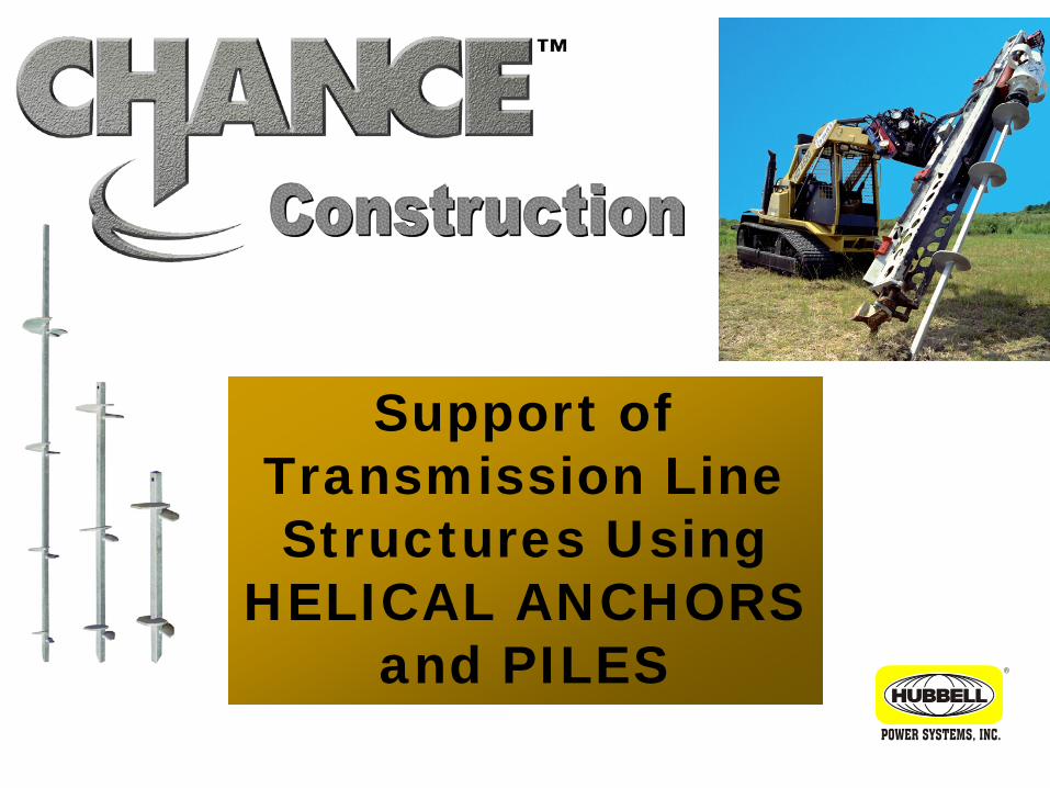
Support of Transmission Line Structures Using
HELICAL ANCHORS and PILES
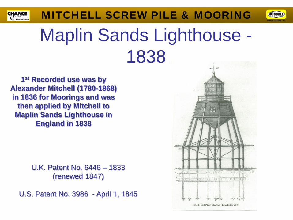
Maplin Sands Lighthouse - 1838
MITCHELL SCREW PILE & MOORING
1st Recorded use was by Alexander Mitchell (1780-1868) in 1836 for Moorings and was
then applied by Mitchell to Maplin Sands Lighthouse in
England in 1838
U.K. Patent No. 6446 – 1833 (renewed 1847)
U.S. Patent No. 3986 - April 1, 1845

Advantages – Screw Anchors/Piles • Quick, Easy Turnkey
Installation • Immediate Loading • Small Installation Equipment • Pre-Engineered System • Easily Field Modified • Torque to Capacity Correlation • Install in Any Weather • Solution for:
– Restricted Access Sites – High Water Table – Weak Surface Soils
• Environmentally Friendly – No Vibration – No spoils to Remove – No Concrete
®
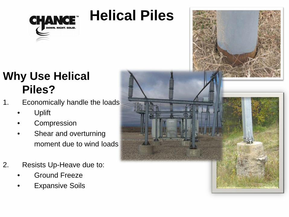
Helical Piles
Why Use Helical Piles?
1. Economically handle the loads • Uplift • Compression • Shear and overturning moment due to wind loads
2. Resists Up-Heave due to:
• Ground Freeze • Expansive Soils
®
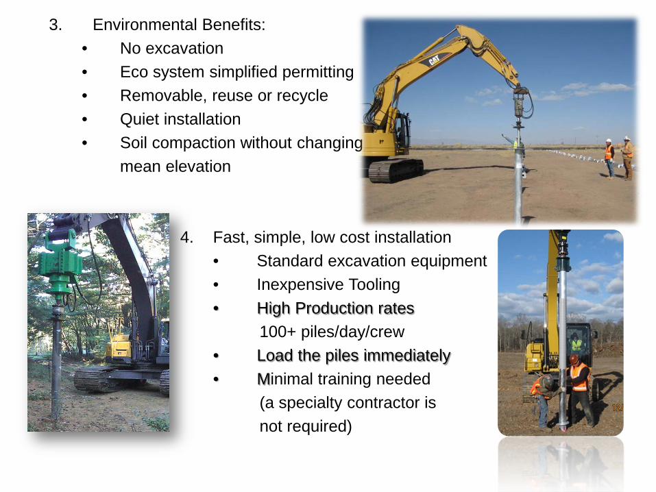
3. Environmental Benefits: • No excavation • Eco system simplified permitting • Removable, reuse or recycle • Quiet installation • Soil compaction without changing mean elevation
4. Fast, simple, low cost installation • Standard excavation equipment • Inexpensive Tooling • High Production rates
100+ piles/day/crew • Load the piles immediately • Minimal training needed
(a specialty contractor is not required)

Square Shaft Helical
Products
CHANCE SCREW ANCHORS SS5,SS150, SS175, SS200 &
SS225
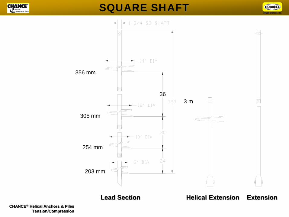
Lead Section Helical Extension Extension CHANCE® Helical Anchors & Piles
Tension/Compression
SQUARE SHAFT
36
203 mm
254 mm
305 mm
356 mm
3 m
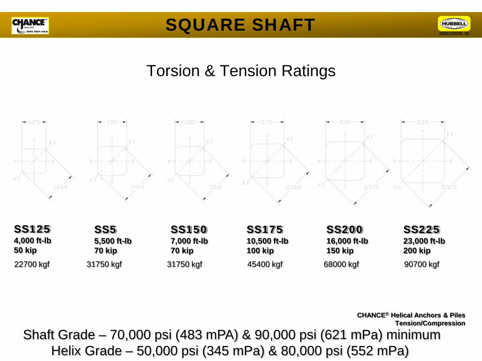
Torsion & Tension Ratings
SS125 4,000 ft-lb 50 kip
SS5 5,500 ft-lb 70 kip
SS150 7,000 ft-lb 70 kip
SS175 10,500 ft-lb 100 kip
SS200 16,000 ft-lb 150 kip
SS225 23,000 ft-lb 200 kip
CHANCE® Helical Anchors & Piles Tension/Compression
SQUARE SHAFT
90700 kgf 68000 kgf 45400 kgf 31750 kgf 31750 kgf 22700 kgf
Shaft Grade – 70,000 psi (483 mPA) & 90,000 psi (621 mPa) minimum Helix Grade – 50,000 psi (345 mPa) & 80,000 psi (552 mPa)
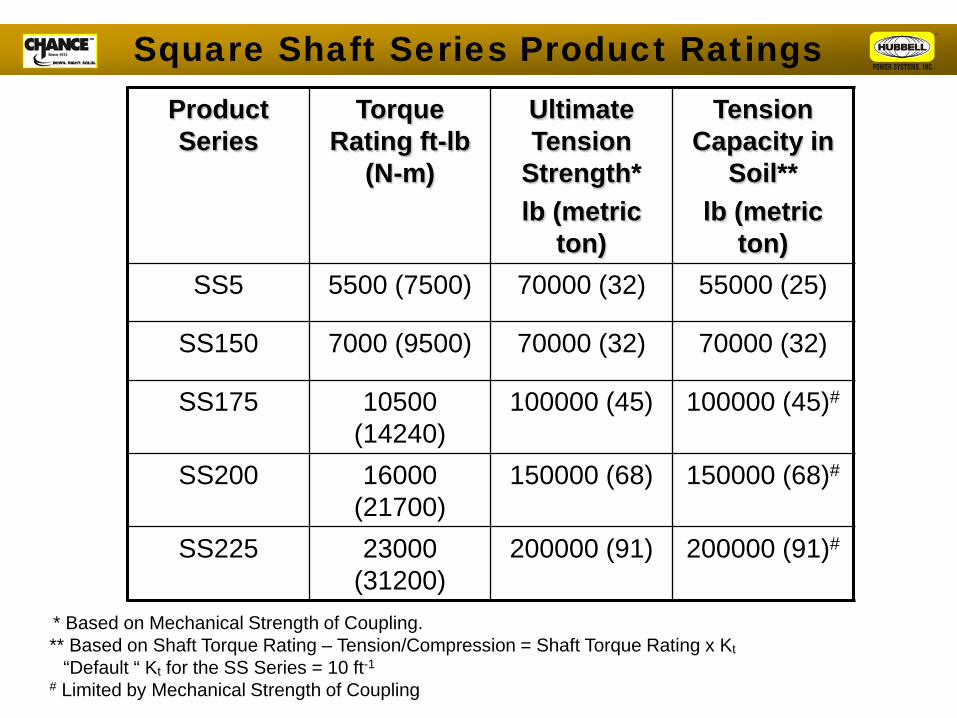
* Based on Mechanical Strength of Coupling. ** Based on Shaft Torque Rating – Tension/Compression = Shaft Torque Rating x Kt
“Default “ Kt for the SS Series = 10 ft-1
# Limited by Mechanical Strength of Coupling
Product Series
Torque Rating ft-lb
(N-m)
Ultimate Tension
Strength* lb (metric
ton)
Tension Capacity in
Soil** lb (metric
ton) SS5 5500 (7500) 70000 (32) 55000 (25)
SS150 7000 (9500) 70000 (32) 70000 (32)
SS175 10500 (14240)
100000 (45) 100000 (45)#
SS200 16000 (21700)
150000 (68) 150000 (68)#
SS225 23000 (31200)
200000 (91) 200000 (91)#
Square Shaft Series Product Ratings
Pipe Shaft Helical
Products
CHANCE SCREW PILES RS2875, RS3500,
RS4500,RS8625, RS10750
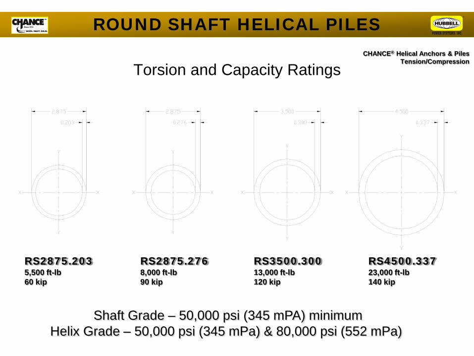
Torsion and Capacity Ratings
RS2875.203 5,500 ft-lb 60 kip
RS2875.276 8,000 ft-lb 90 kip
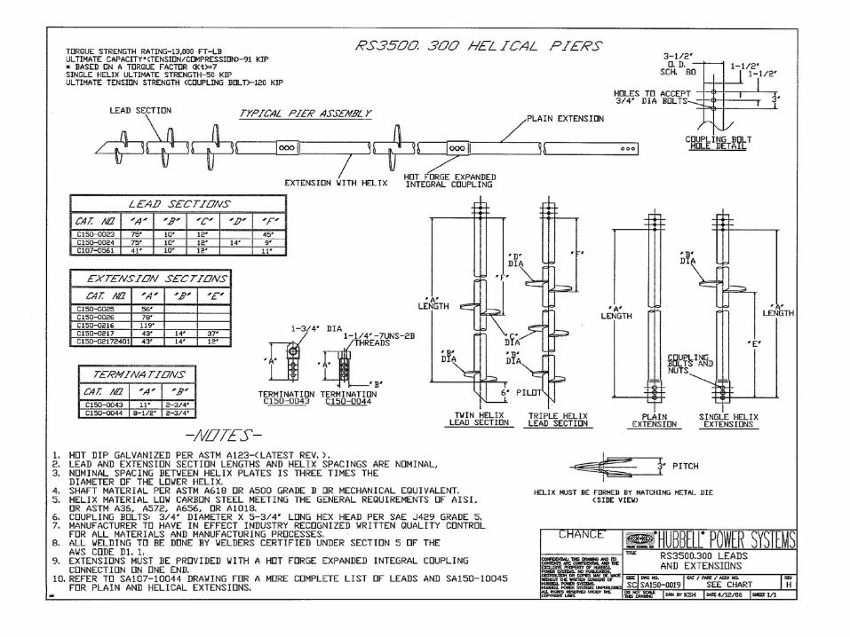
RS3500.300 13,000 ft-lb 120 kip
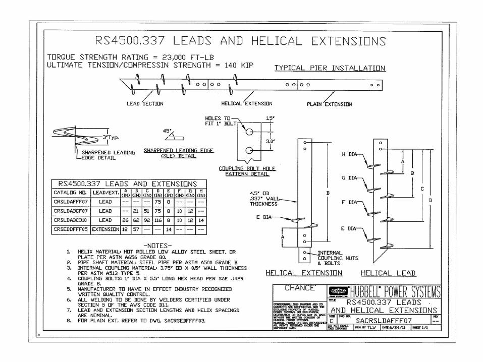
RS4500.337 23,000 ft-lb 140 kip
CHANCE® Helical Anchors & Piles Tension/Compression
ROUND SHAFT HELICAL PILES
Shaft Grade – 50,000 psi (345 mPA) minimum Helix Grade – 50,000 psi (345 mPa) & 80,000 psi (552 mPa)
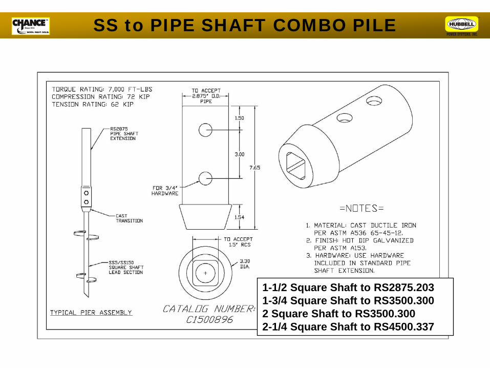
SS to PIPE SHAFT COMBO PILE
1-1/2 Square Shaft to RS2875.203 1-3/4 Square Shaft to RS3500.300 2 Square Shaft to RS3500.300 2-1/4 Square Shaft to RS4500.337
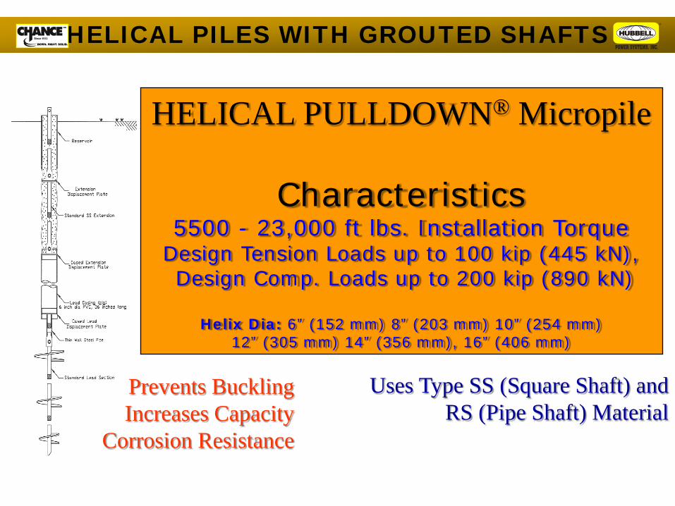
HELICAL PULLDOWN® Micropile
Characteristics 5500 - 23,000 ft lbs. Installation Torque
Design Tension Loads up to 100 kip (445 kN), Design Comp. Loads up to 200 kip (890 kN)
Helix Dia: 6” (152 mm) 8” (203 mm) 10” (254 mm)
12” (305 mm) 14” (356 mm), 16” (406 mm)
Uses Type SS (Square Shaft) and RS (Pipe Shaft) Material
Prevents Buckling Increases Capacity
Corrosion Resistance
HELICAL PILES WITH GROUTED SHAFTS

These Techniques Result in Grouted Helical Anchors
Grouted Helical Piles
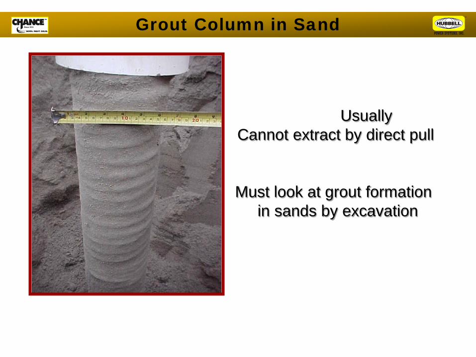
Usually Cannot extract by direct pull
Must look at grout formation in sands by excavation
Grout Column in Sand
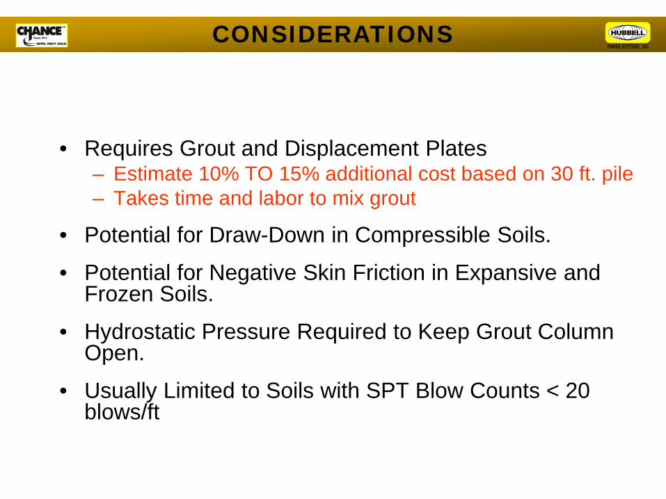
• Requires Grout and Displacement Plates – Estimate 10% TO 15% additional cost based on 30 ft. pile – Takes time and labor to mix grout
• Potential for Draw-Down in Compressible Soils.
• Potential for Negative Skin Friction in Expansive and Frozen Soils.
• Hydrostatic Pressure Required to Keep Grout Column Open.
• Usually Limited to Soils with SPT Blow Counts < 20 blows/ft
CONSIDERATIONS

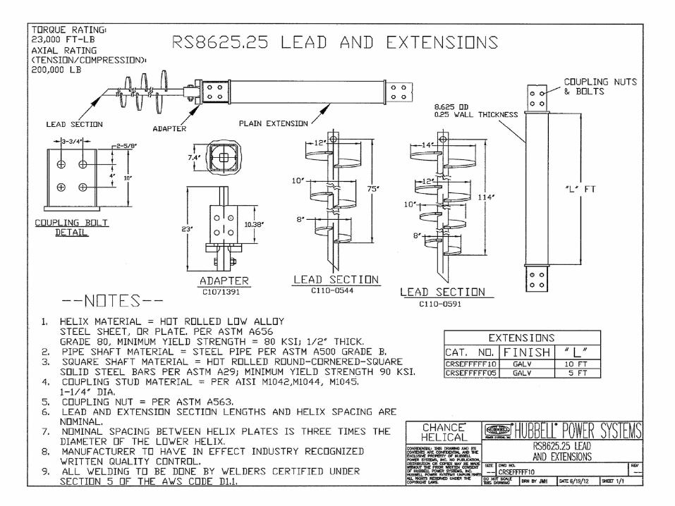
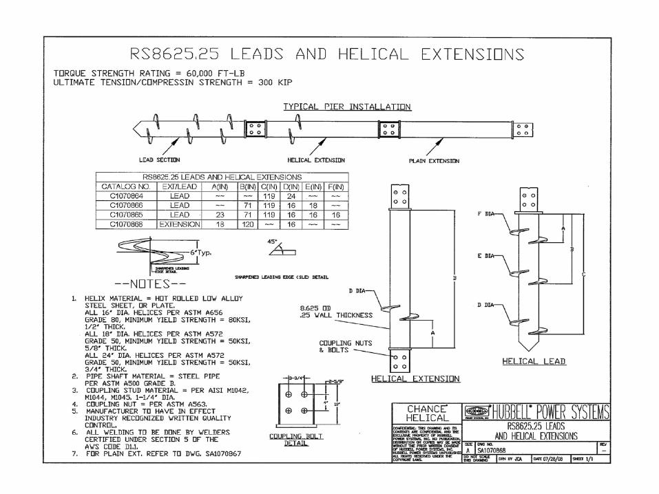
RS8625.250 60,000 ft-lb
300 kip
RS6625.280 40,000 ft-lb
200 kip
LARGE DIAMETER PIPE PILES
219 mm 168 mm
136000 kgf 90700 kgf
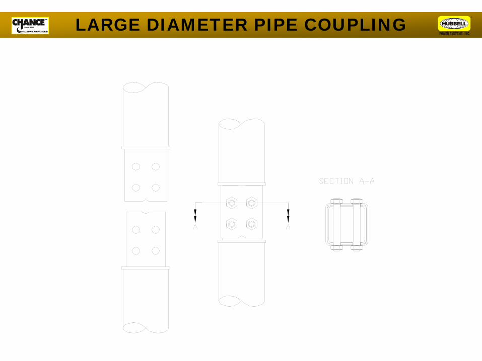
LARGE DIAMETER PIPE COUPLING
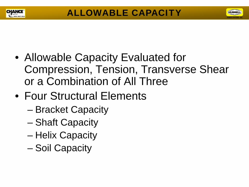
• Allowable Capacity Evaluated for Compression, Tension, Transverse Shear or a Combination of All Three
• Four Structural Elements – Bracket Capacity – Shaft Capacity – Helix Capacity – Soil Capacity
ALLOWABLE CAPACITY
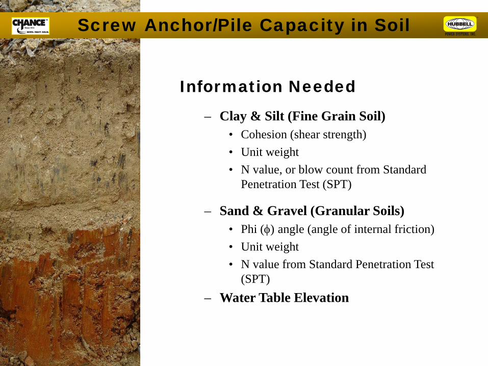
Screw Anchor/Pile Capacity in Soil
Information Needed
– Clay & Silt (Fine Grain Soil) • Cohesion (shear strength) • Unit weight • N value, or blow count from Standard
Penetration Test (SPT)
– Sand & Gravel (Granular Soils) • Phi (φ) angle (angle of internal friction) • Unit weight • N value from Standard Penetration Test
(SPT) – Water Table Elevation
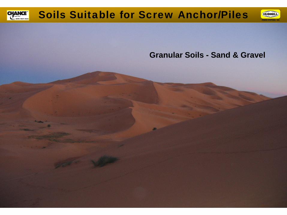
Granular Soils - Sand & Gravel
Soils Suitable for Screw Anchor/Piles
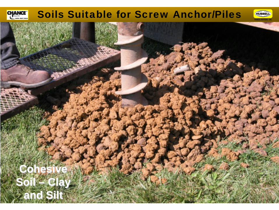
Cohesive Soil – Clay
and Silt
Soils Suitable for Screw Anchor/Piles
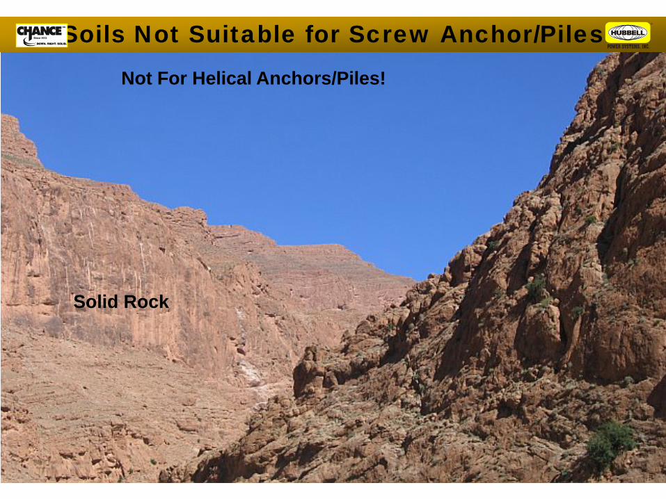
Not For Helical Anchors/Piles!
Solid Rock
Soils Not Suitable for Screw Anchor/Piles
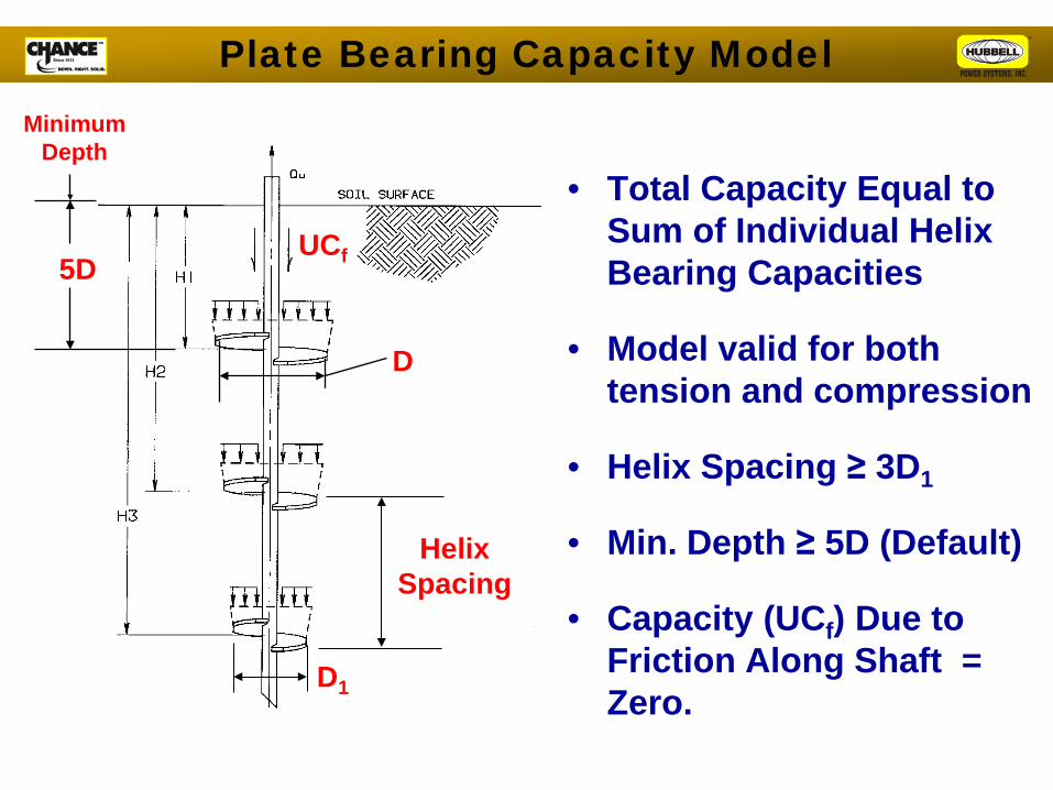
• Total Capacity Equal to Sum of Individual Helix Bearing Capacities
• Model valid for both tension and compression
• Helix Spacing ≥ 3D1
• Min. Depth ≥ 5D (Default)
• Capacity (UCf) Due to Friction Along Shaft = Zero.
5D
Minimum Depth
D
Helix Spacing
D1
UCf
Plate Bearing Capacity Model
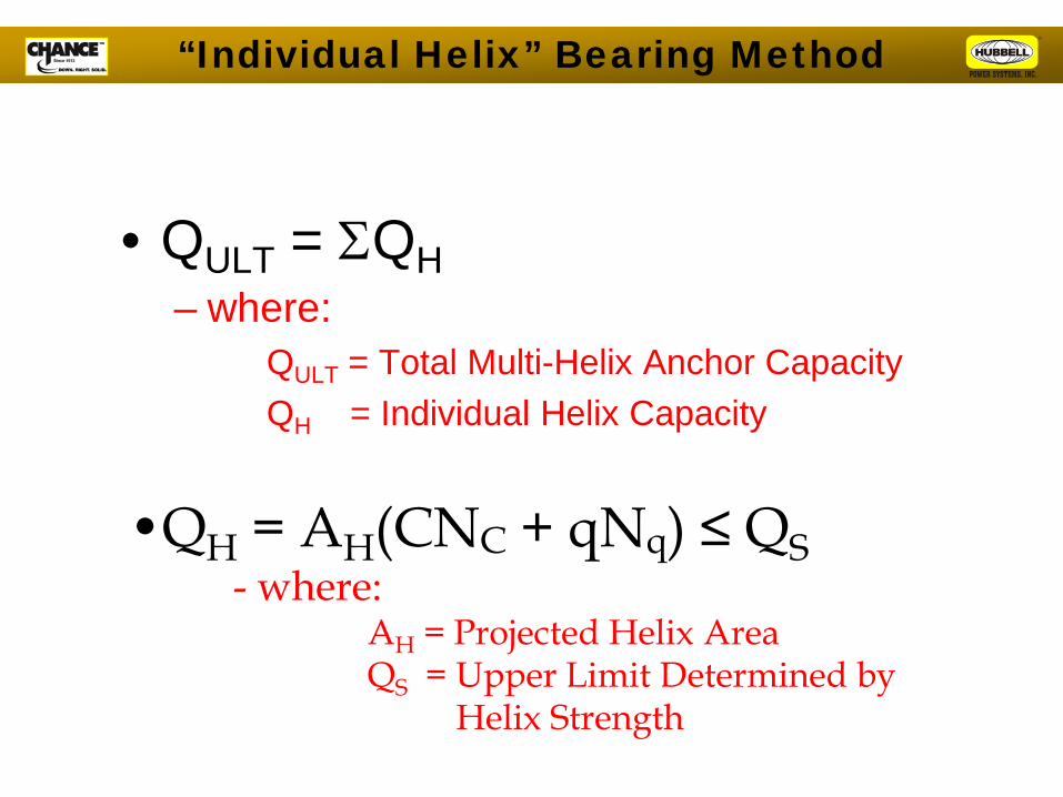
• QULT = ΣQH – where:
QULT = Total Multi-Helix Anchor Capacity QH = Individual Helix Capacity
•QH = AH(CNC + qNq) ≤ QS - where:
AH = Projected Helix Area QS = Upper Limit Determined by Helix Strength
“Individual Helix” Bearing Method
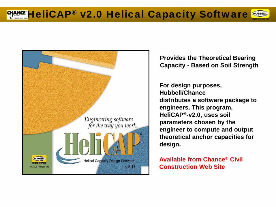
Provides the Theoretical Bearing Capacity - Based on Soil Strength
Available from Chance® Civil Construction Web Site
For design purposes, Hubbell/Chance distributes a software package to engineers. This program, HeliCAP®-v2.0, uses soil parameters chosen by the engineer to compute and output theoretical anchor capacities for design.
HeliCAP® v2.0 Helical Capacity Software
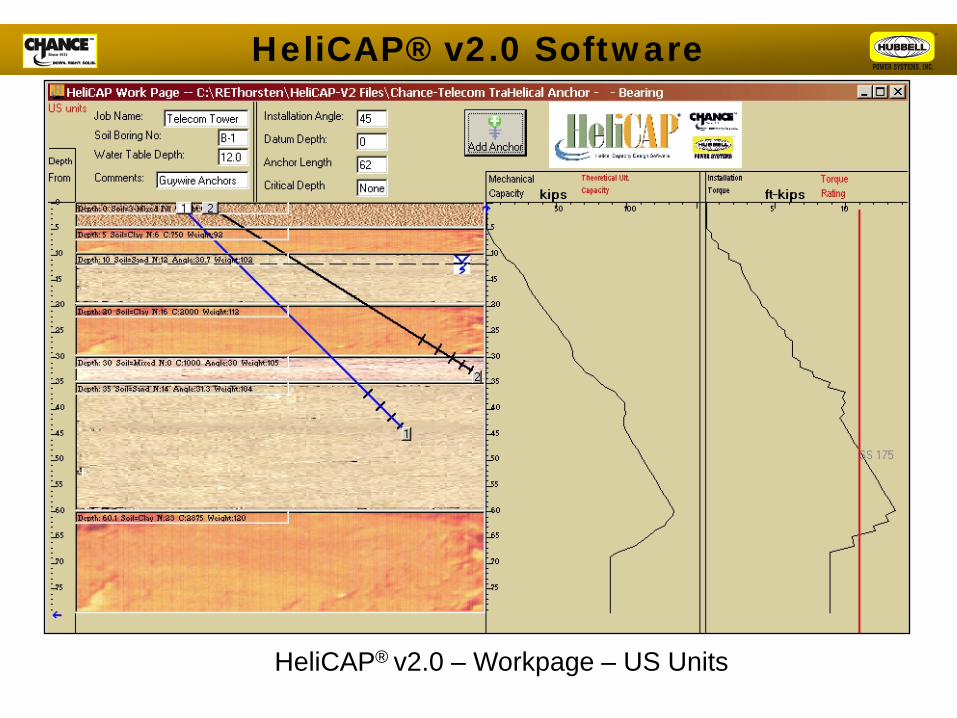
HeliCAP® v2.0 – Workpage – US Units
HeliCAP® v2.0 Software
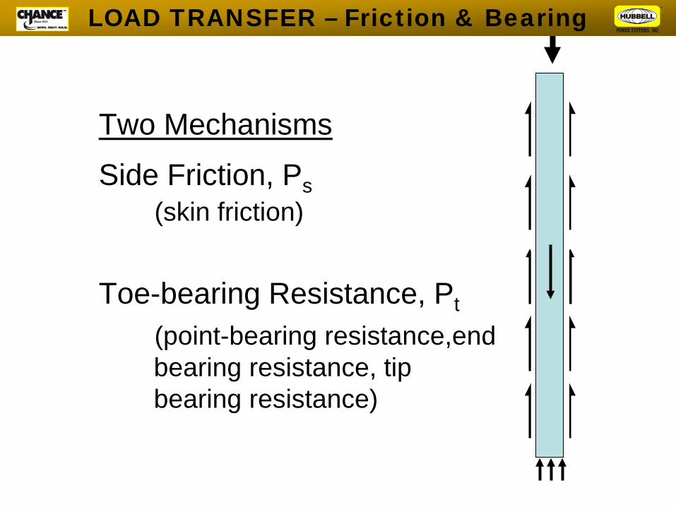
Two Mechanisms
Side Friction, Ps (skin friction)
Toe-bearing Resistance, Pt
(point-bearing resistance,end bearing resistance, tip bearing resistance)
LOAD TRANSFER – Friction & Bearing
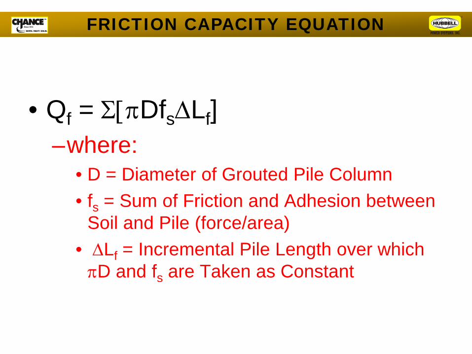
• Qf = Σ[πDfs∆Lf] –where:
• D = Diameter of Grouted Pile Column • fs = Sum of Friction and Adhesion between
Soil and Pile (force/area) • ∆Lf = Incremental Pile Length over which
πD and fs are Taken as Constant
FRICTION CAPACITY EQUATION
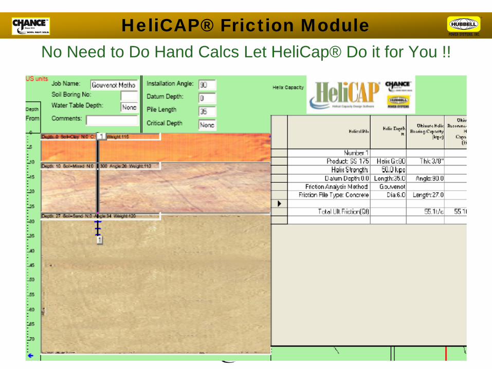
No Need to Do Hand Calcs Let HeliCap® Do it for You !! HeliCAP® Friction Module
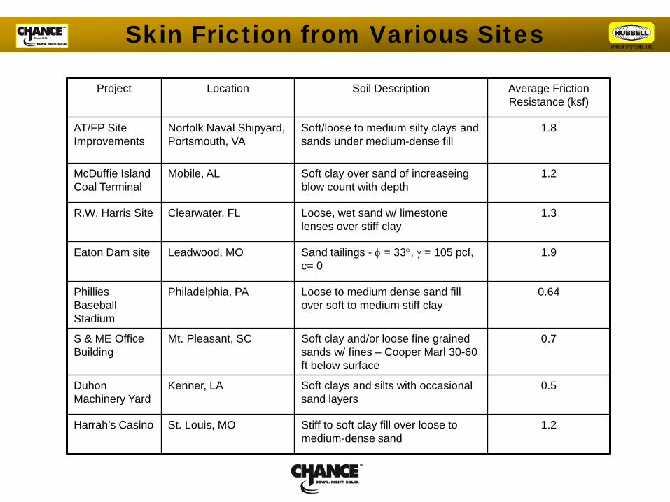
Project Location Soil Description Average Friction Resistance (ksf)
AT/FP Site Improvements
Norfolk Naval Shipyard, Portsmouth, VA
Soft/loose to medium silty clays and sands under medium-dense fill
1.8
McDuffie Island Coal Terminal
Mobile, AL Soft clay over sand of increaseing blow count with depth
1.2
R.W. Harris Site Clearwater, FL Loose, wet sand w/ limestone lenses over stiff clay
1.3
Eaton Dam site Leadwood, MO Sand tailings - φ = 33°, γ = 105 pcf, c= 0
1.9
Phillies Baseball Stadium
Philadelphia, PA Loose to medium dense sand fill over soft to medium stiff clay
0.64
S & ME Office Building
Mt. Pleasant, SC Soft clay and/or loose fine grained sands w/ fines – Cooper Marl 30-60 ft below surface
0.7
Duhon Machinery Yard
Kenner, LA Soft clays and silts with occasional sand layers
0.5
Harrah’s Casino St. Louis, MO Stiff to soft clay fill over loose to medium-dense sand
1.2
Skin Friction from Various Sites

Lateral Analysis Using Finite Difference Methods
(LPILE)
Limiting Criteria: 1. Pile-Head Deflection
2. Bending Moment 3. Shear

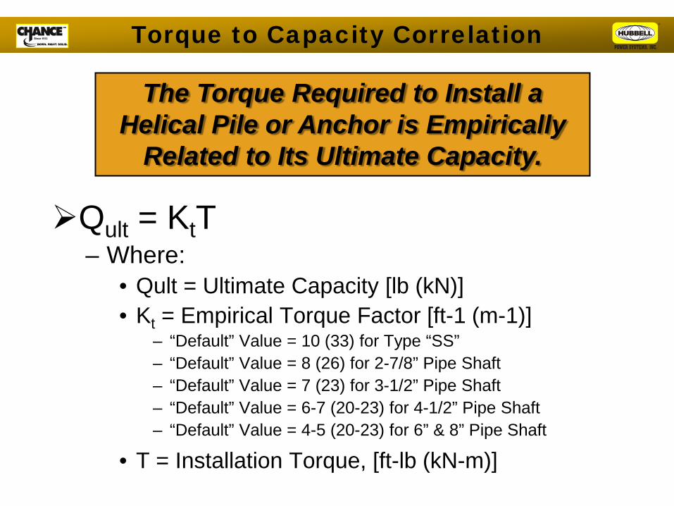
Qult = KtT – Where:
• Qult = Ultimate Capacity [lb (kN)] • Kt = Empirical Torque Factor [ft-1 (m-1)]
– “Default” Value = 10 (33) for Type “SS” – “Default” Value = 8 (26) for 2-7/8” Pipe Shaft – “Default” Value = 7 (23) for 3-1/2” Pipe Shaft – “Default” Value = 6-7 (20-23) for 4-1/2” Pipe Shaft – “Default” Value = 4-5 (20-23) for 6” & 8” Pipe Shaft
• T = Installation Torque, [ft-lb (kN-m)]
The Torque Required to Install a Helical Pile or Anchor is Empirically
Related to Its Ultimate Capacity.
Torque to Capacity Correlation
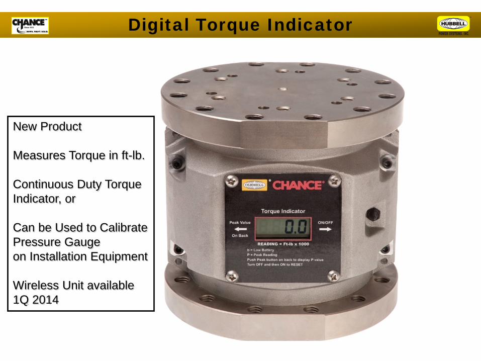
Digital Torque Indicator
New Product Measures Torque in ft-lb. Continuous Duty Torque Indicator, or Can be Used to Calibrate Pressure Gauge on Installation Equipment Wireless Unit available 1Q 2014
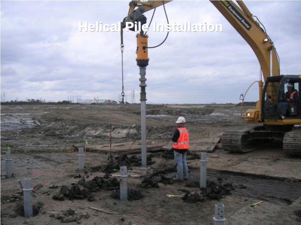
Helical Pile Installation

INSTALLATION LOG – TORQUE VS. DEPTH SSI75 w/ 8, 10, 12 & 14 in HELICES, LENGTH 31 FT
VERTICAL INSTALLATION – CLAY SOIL
DEPTH (ft)
TOR
QU
E (ft
-lb)
Torque at Termination: Best if Steady or Increasing
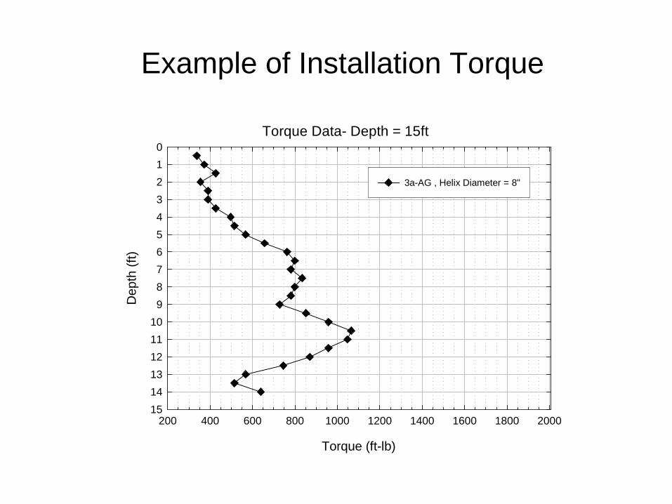
Example of Installation Torque
Torque Data- Depth = 15ft
Torque (ft-lb)
200 400 600 800 1000 1200 1400 1600 1800 2000
Dep
th (f
t)0123456789
101112131415
3a-AG , Helix Diameter = 8"
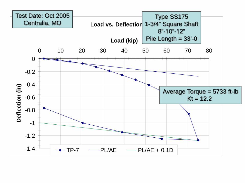
Load vs. Deflection
-1.4
-1.2
-1
-0.8
-0.6
-0.4
-0.2
00 10 20 30 40 50 60 70 80
Load (kip)
Def
lect
ion
(in)
TP-7 PL/AE PL/AE + 0.1D
Test Date: Oct 2005 Centralia, MO
Type SS175 1-3/4” Square Shaft
8”-10”-12” Pile Length = 33’-0
Average Torque = 5733 ft-lb Kt = 12.2

Torque Correlation – AC358 • Section 3.13.2 Torque Correlation
Verification – Conforming Systems
• 1.5” & 1.75” Square Shaft Kt = 10 • 2-7/8 OD Pipe Shaft Kt = 9 • 3” OD Pipe Shaft Kt = 8 • 3-1/2” OD Pipe Shaft Kt = 7 • Verification Requires 14 Full-Scale Load Tests in
Soil – Non-Conforming Systems
• Verification Requires 28 Full-Scale Load Tests in Soil
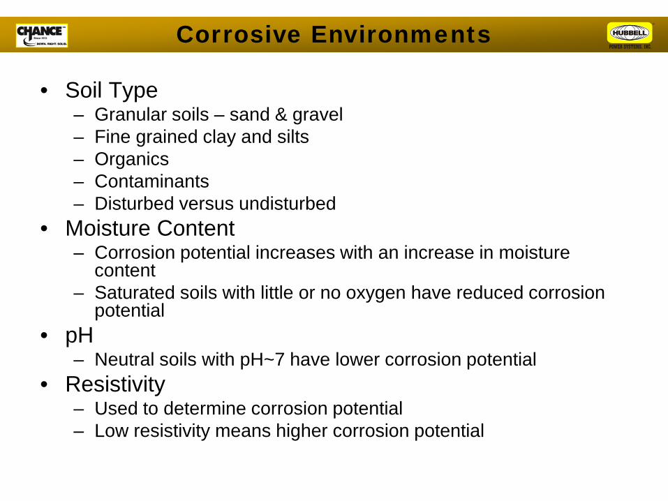
• Soil Type – Granular soils – sand & gravel – Fine grained clay and silts – Organics – Contaminants – Disturbed versus undisturbed
• Moisture Content – Corrosion potential increases with an increase in moisture
content – Saturated soils with little or no oxygen have reduced corrosion
potential • pH
– Neutral soils with pH~7 have lower corrosion potential • Resistivity
– Used to determine corrosion potential – Low resistivity means higher corrosion potential
Corrosive Environments
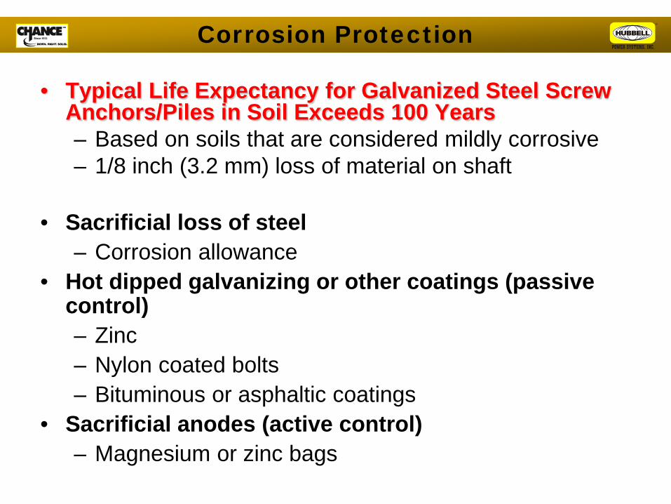
• Typical Life Expectancy for Galvanized Steel Screw Anchors/Piles in Soil Exceeds 100 Years – Based on soils that are considered mildly corrosive – 1/8 inch (3.2 mm) loss of material on shaft
• Sacrificial loss of steel
– Corrosion allowance • Hot dipped galvanizing or other coatings (passive
control) – Zinc – Nylon coated bolts – Bituminous or asphaltic coatings
• Sacrificial anodes (active control) – Magnesium or zinc bags
Corrosion Protection
Applications
Transmission and Substation

Steel Pole LineSingle Mast
Mono-Pole Line
Loads
Deflected Shape
WIND PRESSURE ON POLE

Moment (M)
Force (F)
Wind Pressure (P)
LOAD at GROUNDLINE
Moment – Large Shear – Moderate
Compression - Light
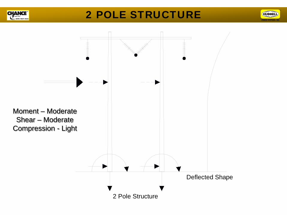
Deflected Shape
2 Pole Structure
2 POLE STRUCTURE
Moment – Moderate Shear – Moderate
Compression - Light
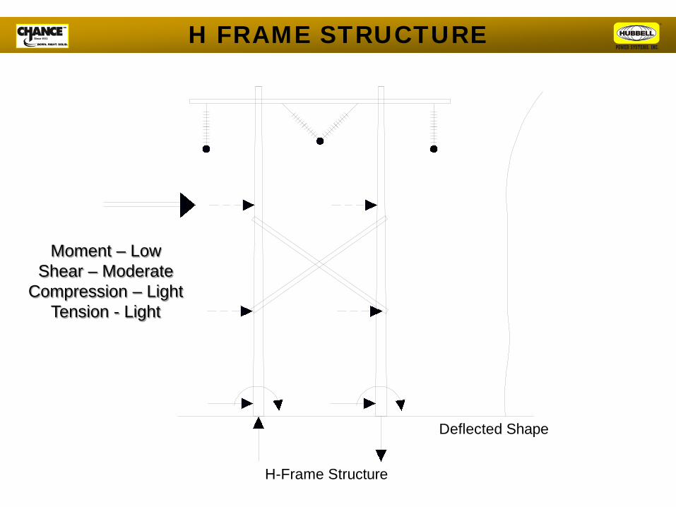
Deflected Shape
H-Frame Structure
Moment – Low Shear – Moderate
Compression – Light Tension - Light
H FRAME STRUCTURE
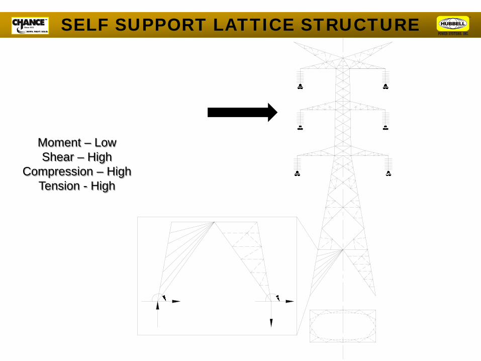
SELF SUPPORT LATTICE STRUCTURE
Moment – Low Shear – High
Compression – High Tension - High
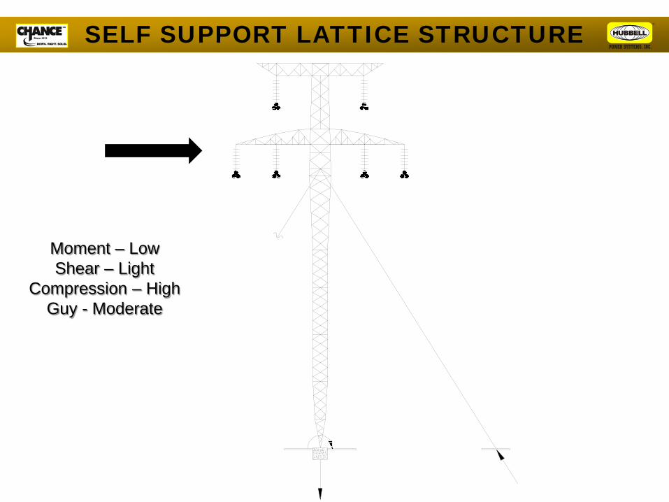
Moment – Low Shear – Light
Compression – High Guy - Moderate
SELF SUPPORT LATTICE STRUCTURE
Structure: Guyed Steel H-Frame Construction Location: Saskatoon to Regina, Saskatchewan Soil: Medium dense sand and gravel.
Some isolated pockets of stiff clay.
Frost Depth: 7 feet
Saskpower 230 kV Transmission Line

Type 1 Anchorage 221 kN (50 kip) Acceptance Criteria: No anchor creep greater than 12 mm
(1/2 inch) allowed after 60 seconds at this pull-out load.
Type 2 Anchorage 275 kN (62 kip) Acceptance Criteria: No anchor creep greater than 12 mm
(1/2 inch) allowed after 60 seconds at this pull-out load.
Type 3 Anchorage 400 kN (90 kip) Acceptance Criteria: No anchor creep greater than 12 mm
(1/2 inch) allowed after 60 seconds at this pull-out load.
Saskpower 230 kV Transmission Line
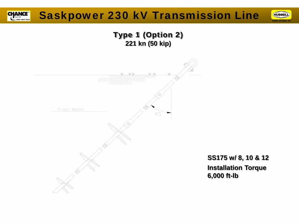
SS175 w/ 8, 10 & 12
Installation Torque 6,000 ft-lb
Type 1 (Option 2) 221 kn (50 kip)
Saskpower 230 kV Transmission Line
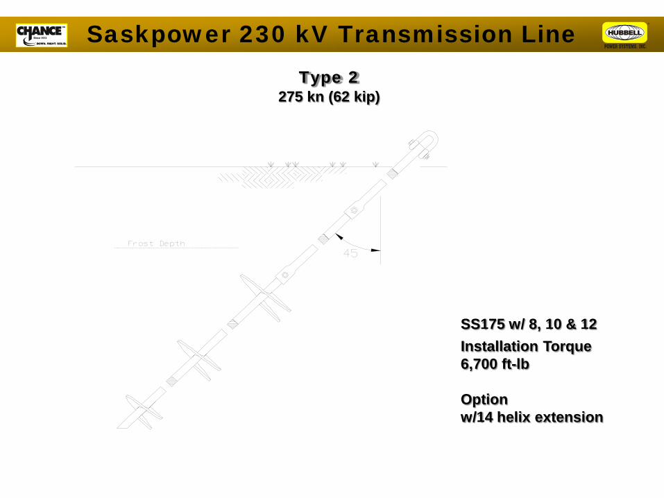
SS175 w/ 8, 10 & 12
Installation Torque 6,700 ft-lb Option w/14 helix extension
Type 2 275 kn (62 kip)
Saskpower 230 kV Transmission Line
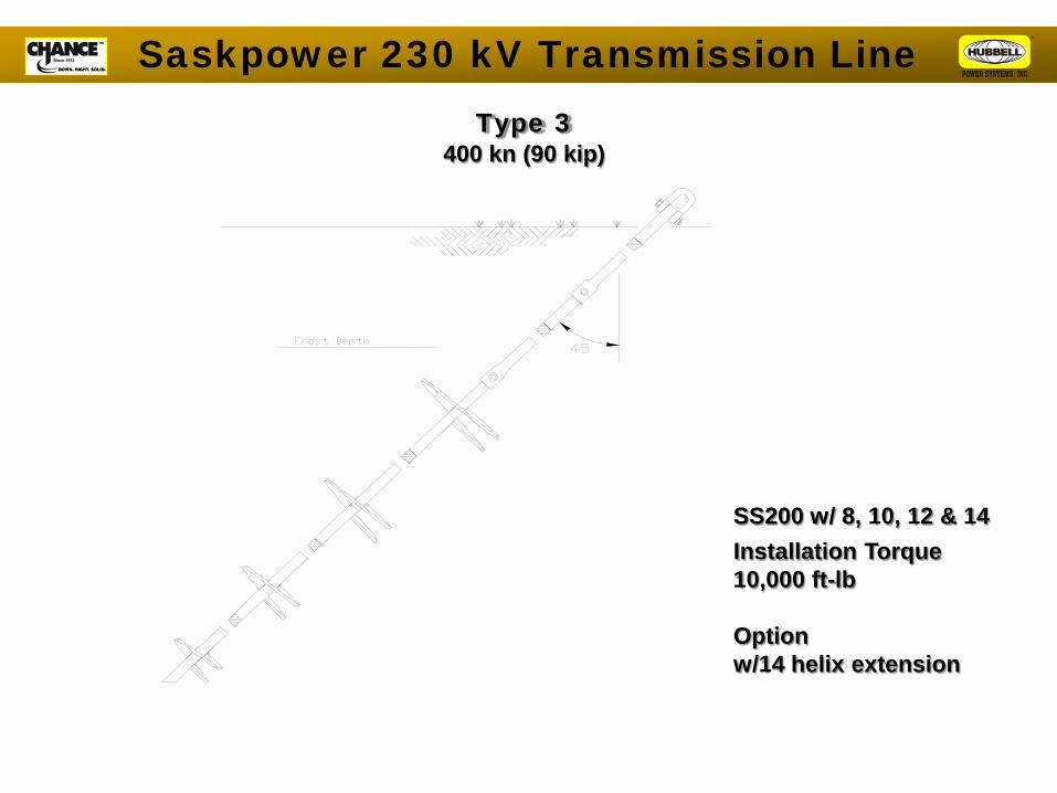
SS200 w/ 8, 10, 12 & 14
Installation Torque 10,000 ft-lb Option w/14 helix extension
Type 3 400 kn (90 kip)
Saskpower 230 kV Transmission Line

Saskpower 230 kV Transmission Line
RIO MADEIRA PROJECT
600kV dc Line
June 2010 Update

“B” Cuiaba – Rio Verde
500kV Line HB 602km - Cymi
“G” Porto Velho – Araraquara 2 600kV Line CC
2375km Consorcio Integração Norte
“D” Porto Velho – Araraquara 1
600kV Line CC 2375km - Consorcio Madeira
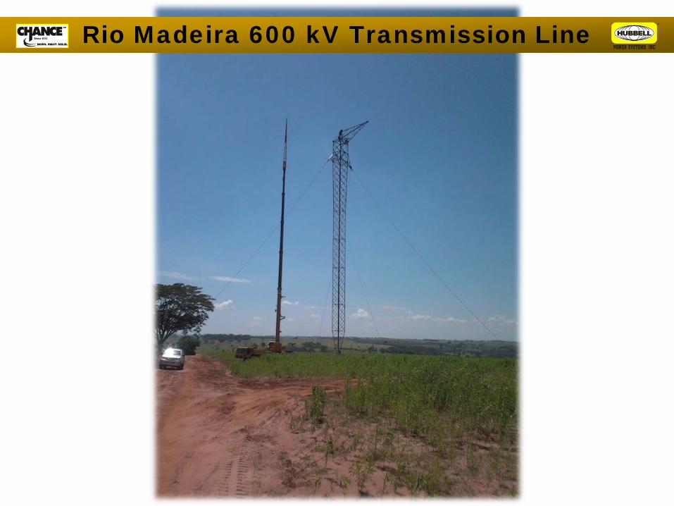
Rio Madeira 600 kV Transmission Line

Rio Madeira 600 kV Transmission Line
CHANCE Type SS200 Helical Anchor
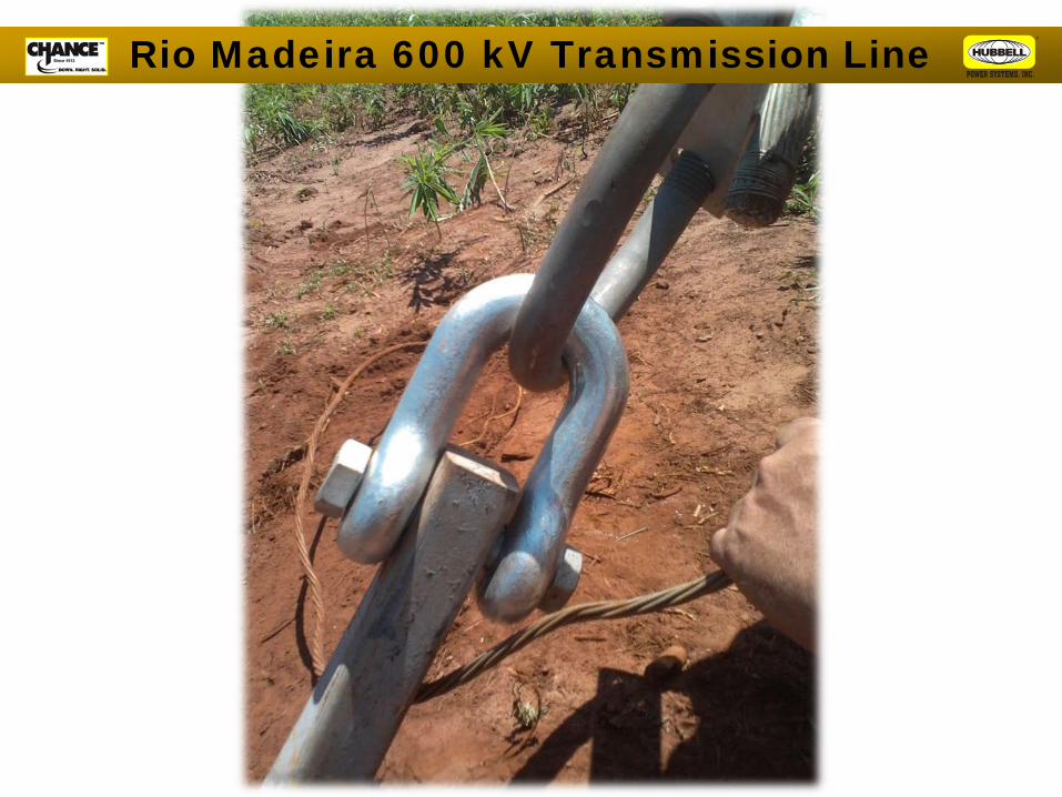
Rio Madeira 600 kV Transmission Line

Ejemplo para uso en anclaje de Tirante
Linha Porto Velho-Araraquara
Tipo: Estaca maciza
Modelo SS200
Carga ruptura: 68t
Torque Instalacion: 14,000 ft-lbs

Tension Test to Ultimate Capacity

Tension Test Type SS200 Anchor
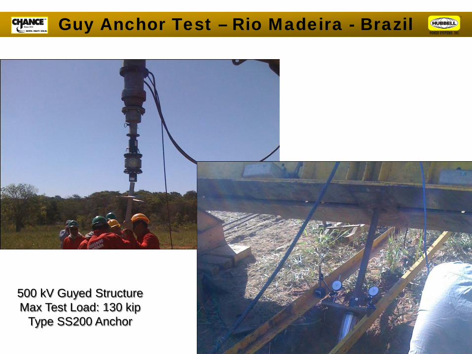
Guy Anchor Test – Rio Madeira - Brazil
500 kV Guyed Structure Max Test Load: 130 kip
Type SS200 Anchor

Engevix - Brazil
Transmissora Sul Litoranea De Energia, S.A.
LT 525 kV Marmeleiro – Povo Novo
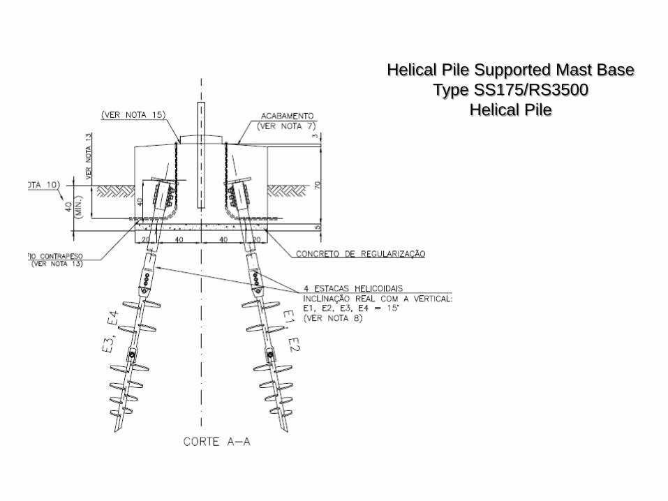
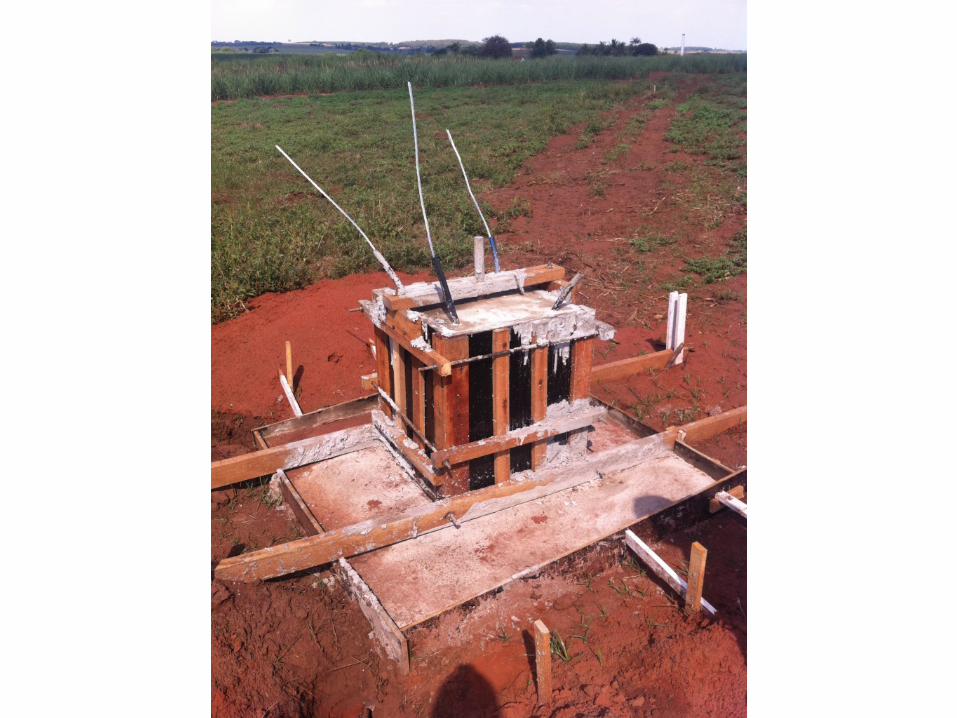
Helical Pile Supported Mast Base Type SS175/RS3500
Helical Pile

Helical Guy Anchor Supported Tower Type SS200 Anchors

Helical Pile Supported Tower Base 4-Legged Self-Support
Type SS175/RS3500 Helical Piles
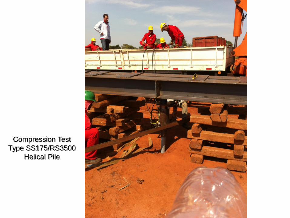
Compression Test Type SS175/RS3500
Helical Pile

San Pedero Sula - Honduras
Caracol Knit - 132 kV Electrical Feed for Biomass and Textile
Plants
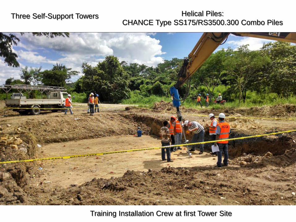
Three Self-Support Towers
Training Installation Crew at first Tower Site
Helical Piles: CHANCE Type SS175/RS3500.300 Combo Piles
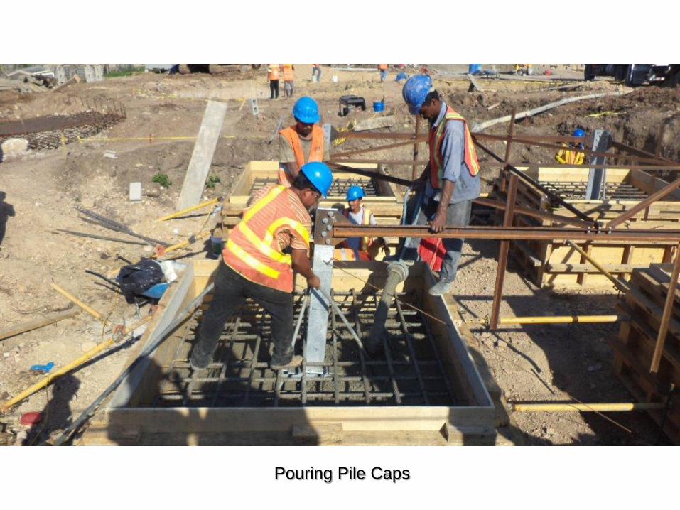
Pouring Pile Caps
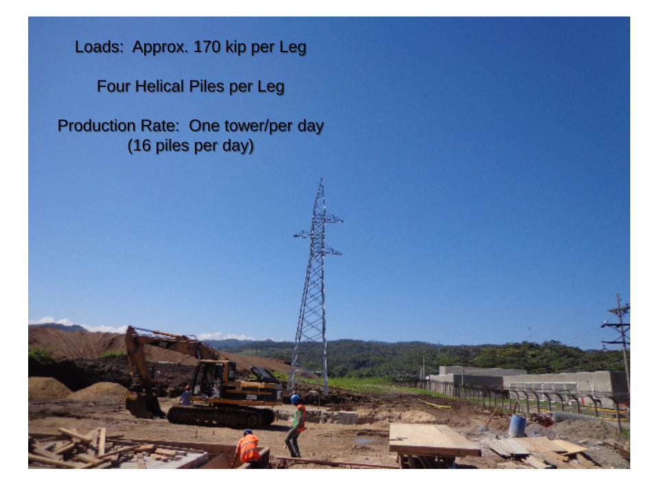
Loads: Approx. 170 kip per Leg
Four Helical Piles per Leg
Production Rate: One tower/per day (16 piles per day)
Xcel Energy
Stinson-Bayfront Helical Pile Foundations
Line 3315, 32.1 mile rebuild 115 kV H-Frame
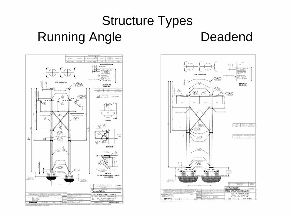
Structure Types Running Angle Deadend
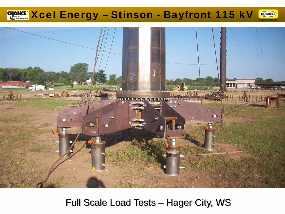
Xcel Energy – Stinson - Bayfront 115 kV
Full Scale Load Tests – Hager City, WS

Load Cases
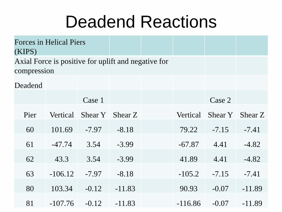
Forces in Helical Piers (KIPS) Axial Force is positive for uplift and negative for compression
Deadend
Case 1 Case 2
Pier Vertical Shear Y Shear Z Vertical Shear Y Shear Z
60 101.69 -7.97 -8.18 79.22 -7.15 -7.41
61 -47.74 3.54 -3.99 -67.87 4.41 -4.82
62 43.3 3.54 -3.99 41.89 4.41 -4.82
63 -106.12 -7.97 -8.18 -105.2 -7.15 -7.41
80 103.34 -0.12 -11.83 90.93 -0.07 -11.89
81 -107.76 -0.12 -11.83 -116.86 -0.07 -11.89
Deadend Reactions
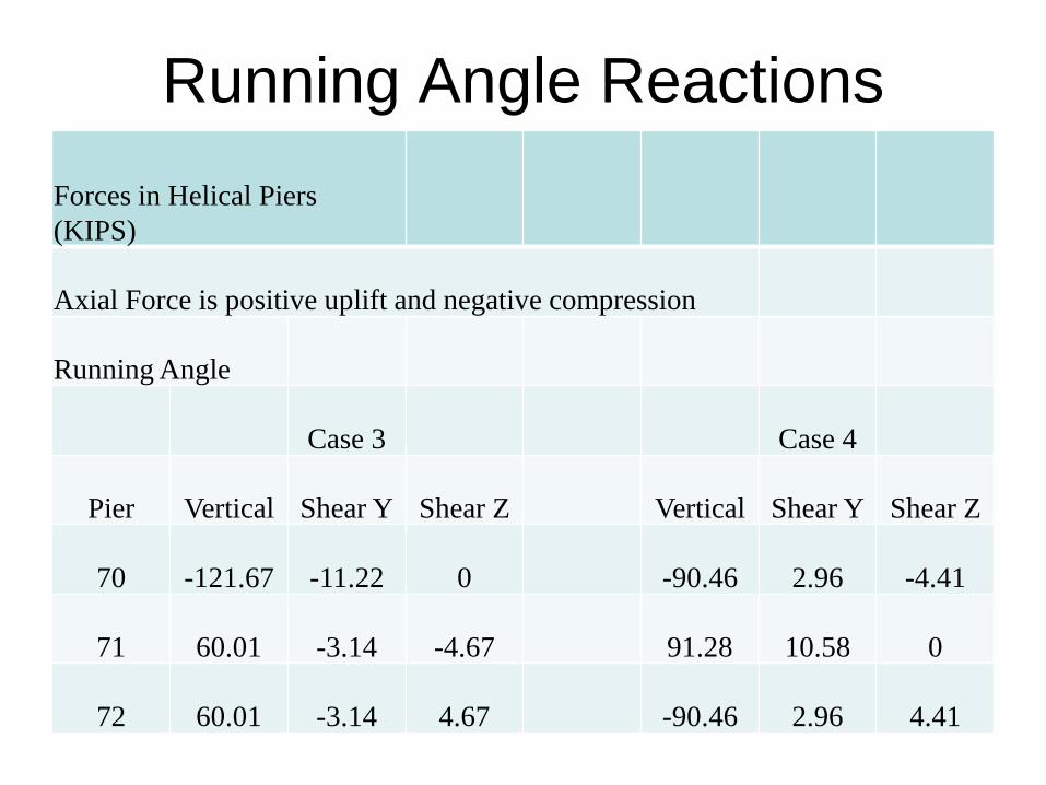
Forces in Helical Piers (KIPS)
Axial Force is positive uplift and negative compression
Running Angle
Case 3 Case 4
Pier Vertical Shear Y Shear Z Vertical Shear Y Shear Z
70 -121.67 -11.22 0 -90.46 2.96 -4.41
71 60.01 -3.14 -4.67 91.28 10.58 0
72 60.01 -3.14 4.67 -90.46 2.96 4.41
Running Angle Reactions
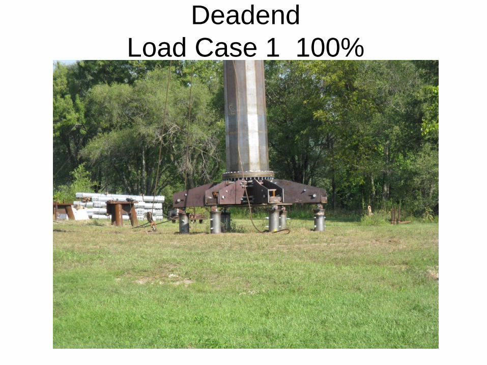
Deadend Load Case 1 100%

Deadend Case 1 @100% Case 2 @ 100%
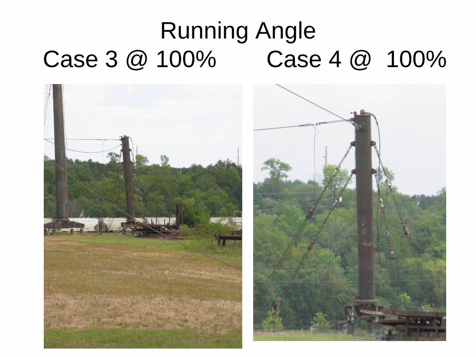
Running Angle Case 3 @ 100% Case 4 @ 100%
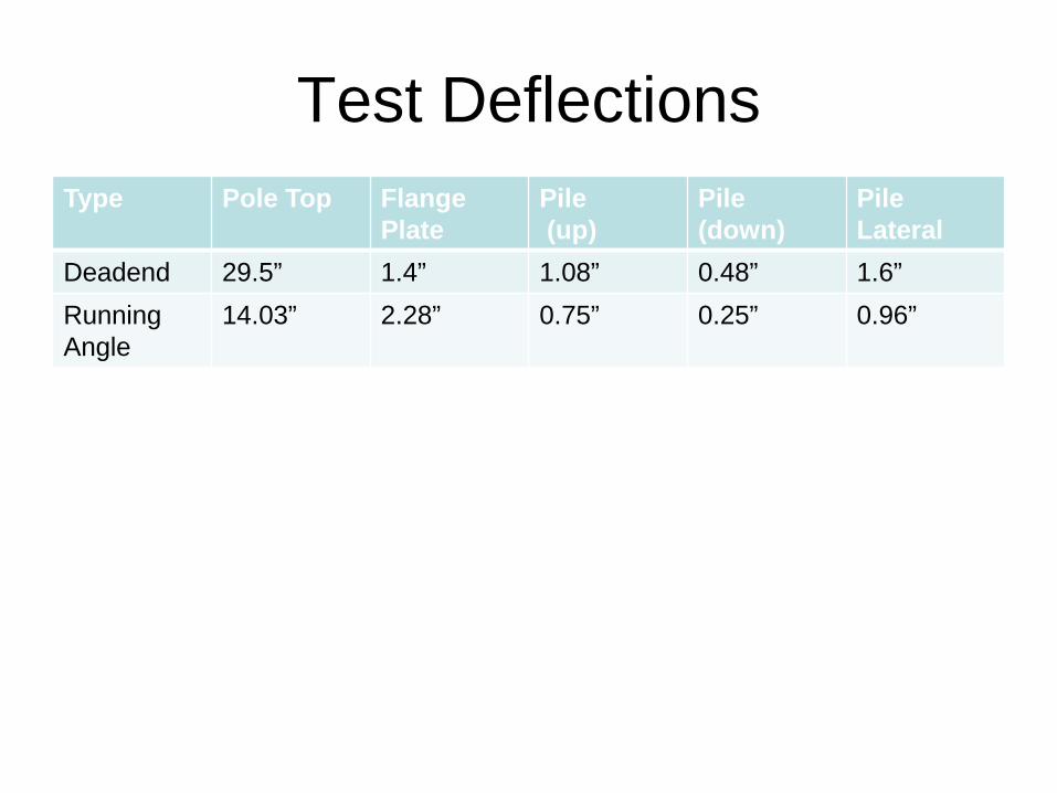
Type Pole Top Flange Plate
Pile (up)
Pile (down)
Pile Lateral
Deadend 29.5” 1.4” 1.08” 0.48” 1.6” Running Angle
14.03” 2.28” 0.75” 0.25” 0.96”
Test Deflections
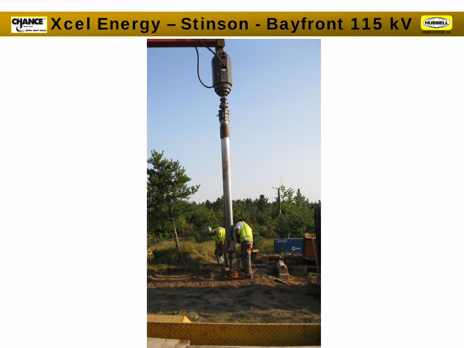
Xcel Energy – Stinson - Bayfront 115 kV
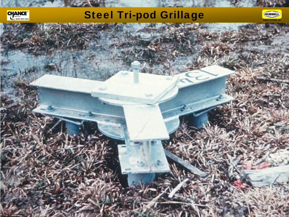
Steel Tri-pod Grillage

Hydro One Networks
Tower Foundation Replacement with Helical Piles
500 kV Guyed V-Shaped Structures
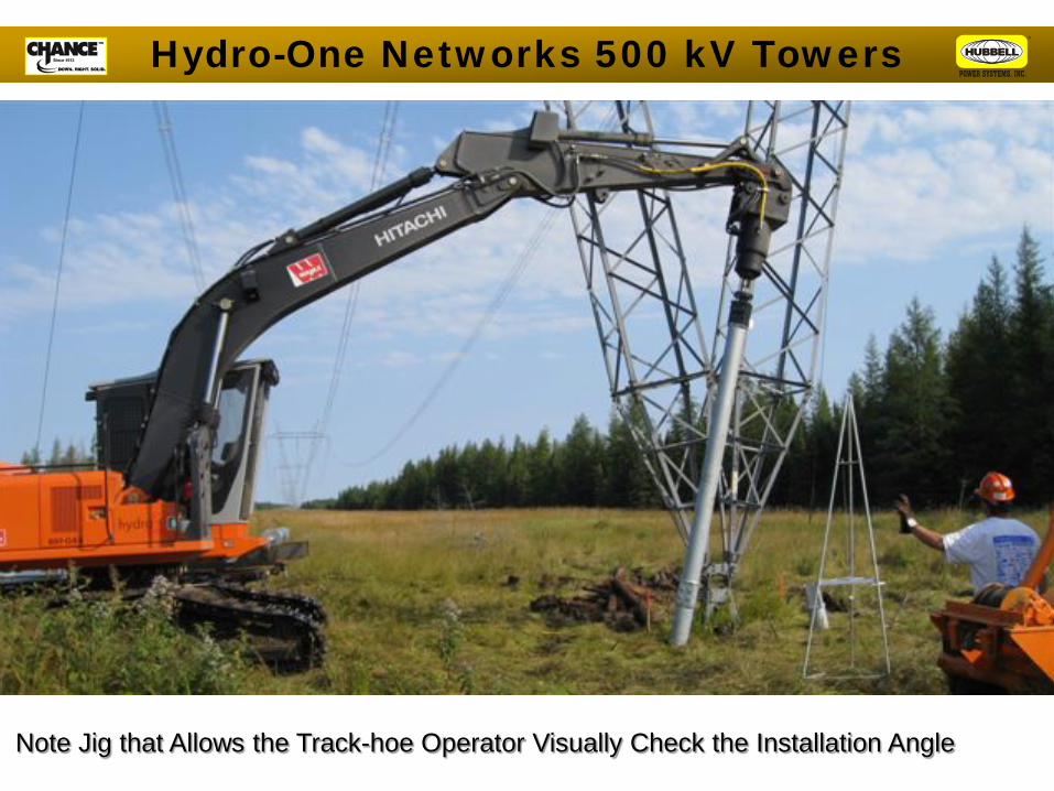
Note Jig that Allows the Track-hoe Operator Visually Check the Installation Angle
Hydro-One Networks 500 kV Towers
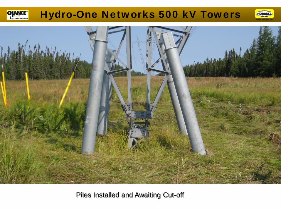
Piles Installed and Awaiting Cut-off
Hydro-One Networks 500 kV Towers
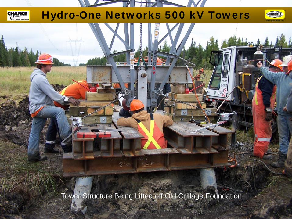
Tower Structure Being Lifted off Old Grillage Foundation
Hydro-One Networks 500 kV Towers

Tower Grillage Complete and Ready for Backfill
Hydro-One Networks 500 kV Towers
Self-Supported Structures
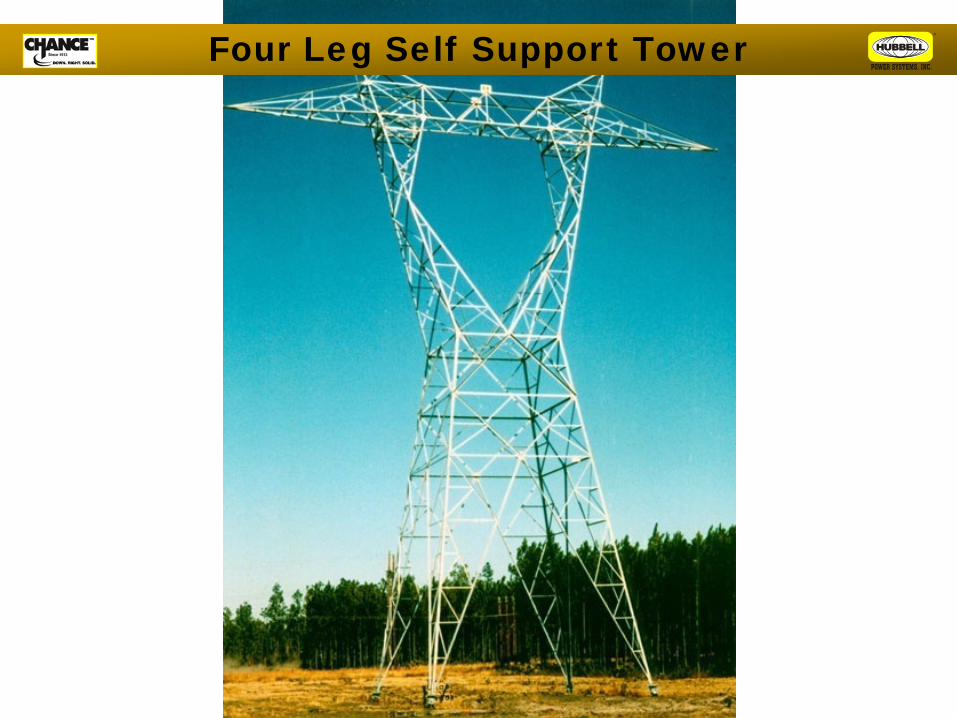
Four Leg Self Support Tower
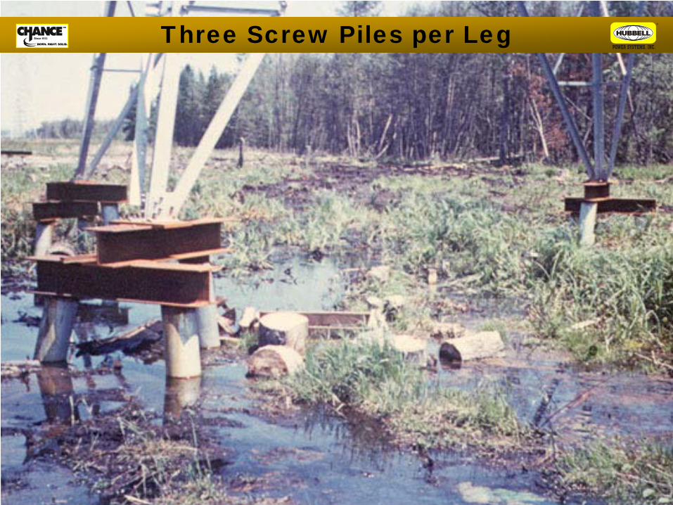
Three Screw Piles per Leg
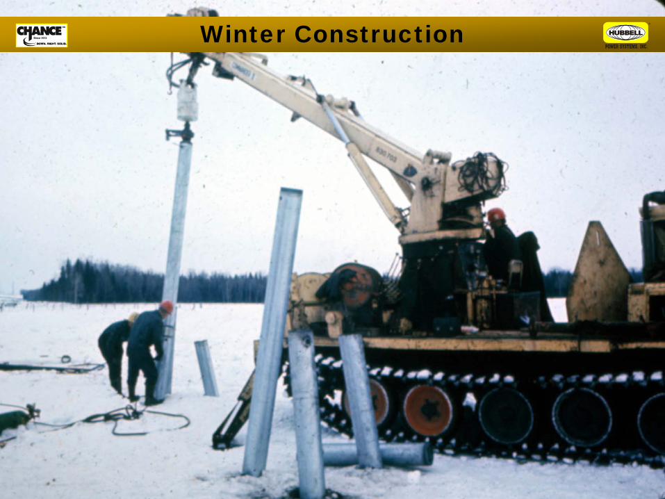
Winter Construction
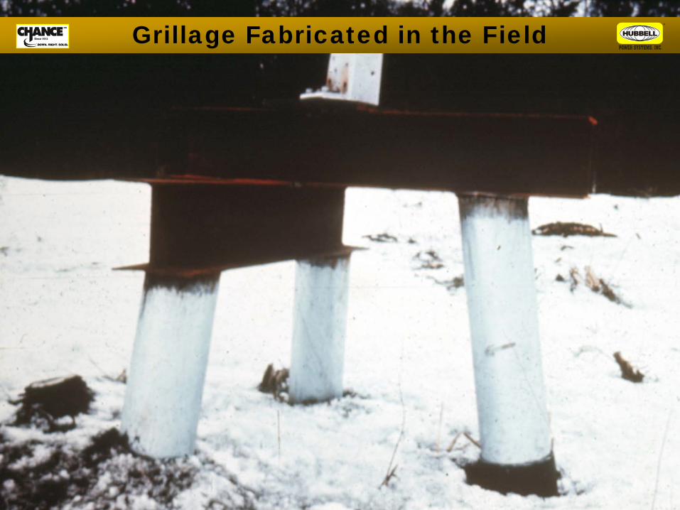
Grillage Fabricated in the Field
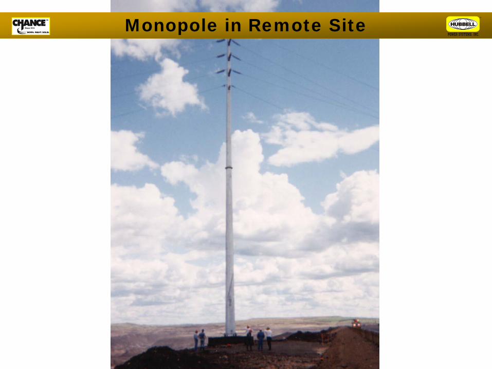
Monopole in Remote Site
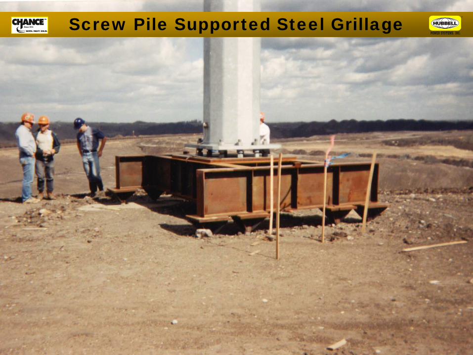
Screw Pile Supported Steel Grillage

330’ Guyed Tower At
Morganza, LA
Fan/Spreader Plate Assembly 7 Guywires to 4 SS5 Series Anchors
Required Total Ultimate Capacity = 150.0 kips
Guyed Telecom Tower
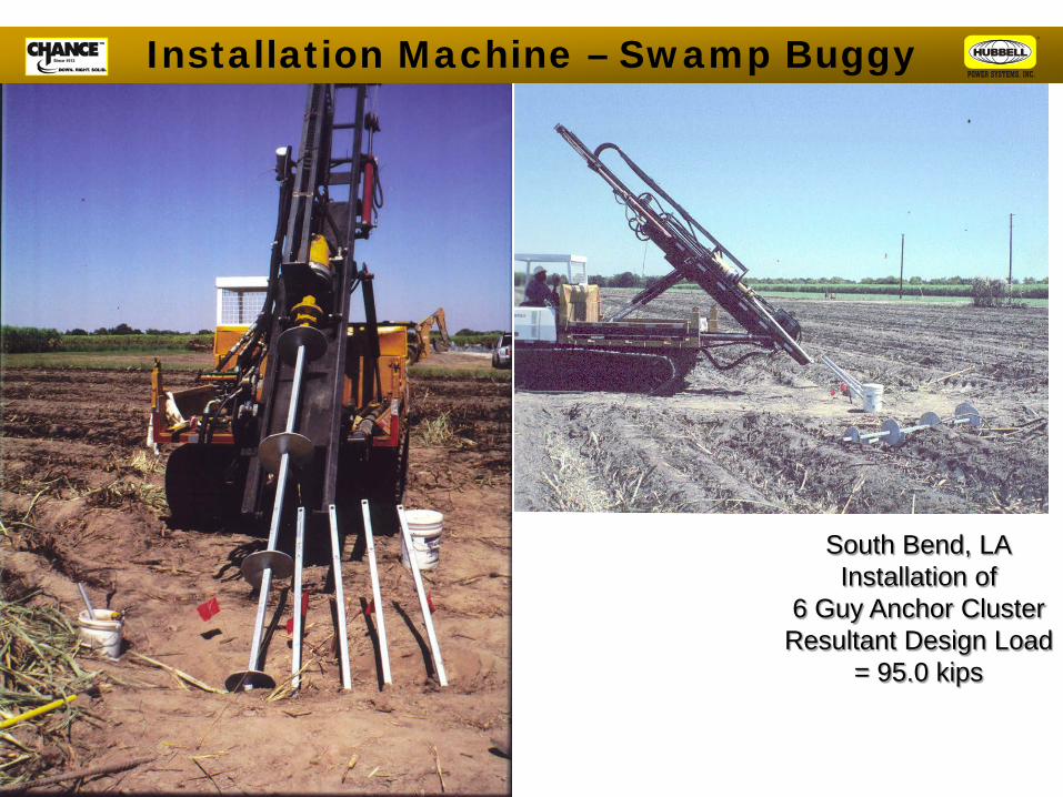
South Bend, LA Installation of
6 Guy Anchor Cluster Resultant Design Load
= 95.0 kips
Installation Machine – Swamp Buggy

South Bend, LA 300’-0 Guyed Tower
12 RS3500.300 Series Piles for Tower Mast Required Ultimate Capacity per Pile = 70.0 kips
Multi-Screw Pile – Concrete Pile Cap
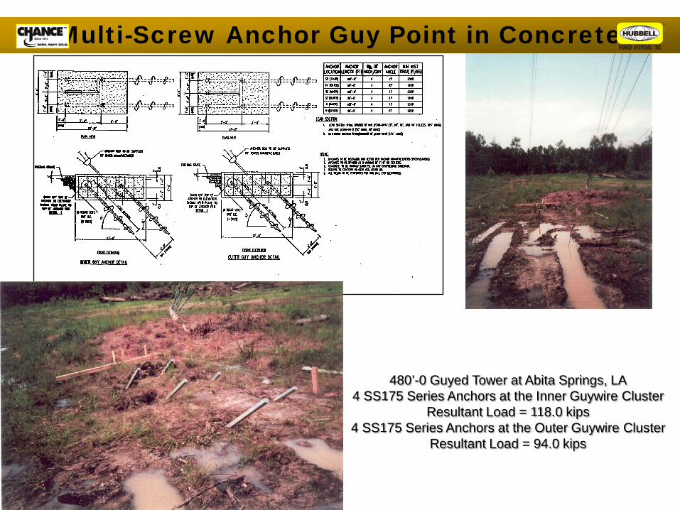
480’-0 Guyed Tower at Abita Springs, LA 4 SS175 Series Anchors at the Inner Guywire Cluster
Resultant Load = 118.0 kips 4 SS175 Series Anchors at the Outer Guywire Cluster
Resultant Load = 94.0 kips
Multi-Screw Anchor Guy Point in Concrete

250’-0 SST at Bayou Blue (Houma), LA 12 Stepped Helical Pulldown® Micropile per tower leg
Ultimate Capacity per pile = 95.0 kips Load Tested to over 100.0 kips in tension
Installed Depths = 70’-0
Multi-Screw Piles with Concrete Cap

250’-0 SST at Bayou Blue (Houma), LA 12 Stepped Helical Pulldown® Micropile
per tower leg Pile Installation using John Deere
Installation Equipment

Augmentation of Existing Foundation
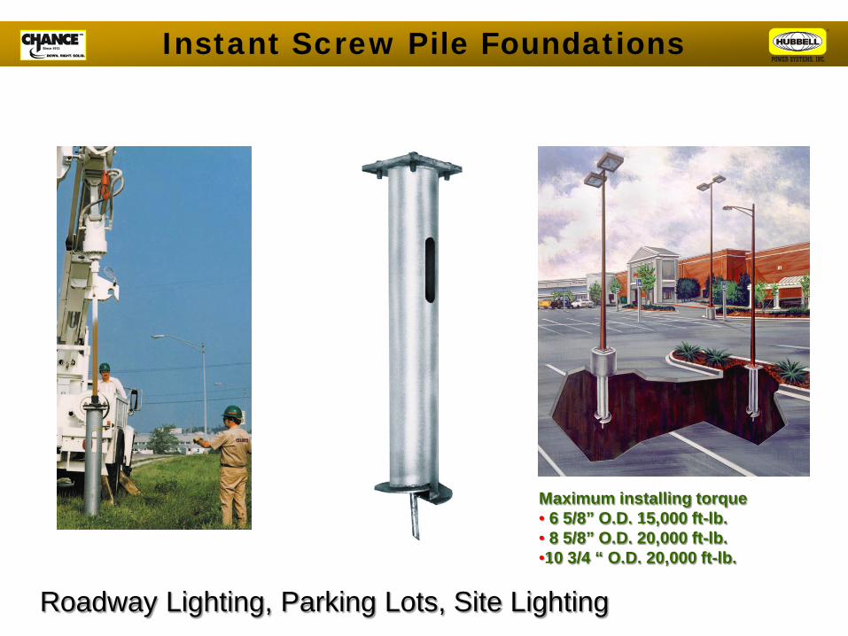
Maximum installing torque • 6 5/8” O.D. 15,000 ft-lb. • 8 5/8” O.D. 20,000 ft-lb. •10 3/4 “ O.D. 20,000 ft-lb.
Instant Screw Pile Foundations
Roadway Lighting, Parking Lots, Site Lighting