doc.: IEEE 802.11-13/1012r4 Submission Nov 2013 Dynamic Sensitivity Control V2 Date: 2013-11 Authors: Graha m Smith Slide 1 N am e C om pany A ddress Phone em ail G raham Smith D SP G roup 1037 Suncast Lane, Ste 112, ElD orado H ills, CA 95762 916 358 8725 Graham.smith@ dspg.com
Transcript
doc.: IEEE 802.11-13/1012r4
Submission
Nov 2013
Dynamic Sensitivity ControlV2
Date: 2013-11
Authors:
Name Company Address Phone email Graham Smith DSP Group 1037 Suncast
(6Mbps)(-82dBm for 20MHz channel, -79dBm for 40MHz channel)
– If no detected header, 20 dB higher, i.e. -62dBm
Nov 2013
Graham
Smith, DSP
Group
Slide 2
doc.: IEEE 802.11-13/1012r4
Submission
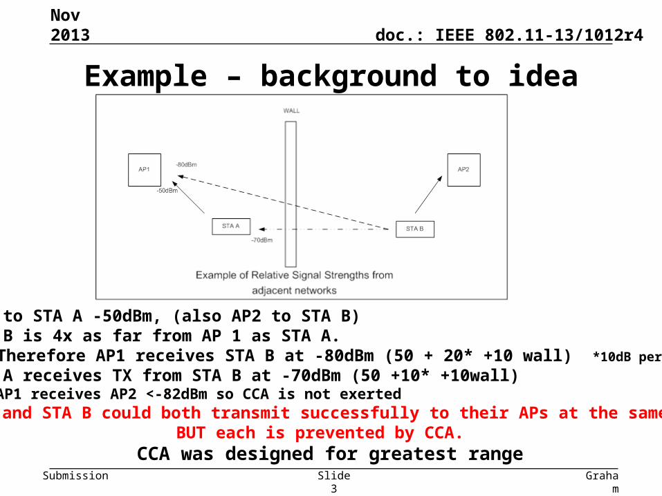
Example – background to idea
• AP1 to STA A -50dBm, (also AP2 to STA B)• STA B is 4x as far from AP 1 as STA A.
• Therefore AP1 receives STA B at -80dBm (50 + 20* +10 wall) *10dB per octave
• STA A receives TX from STA B at -70dBm (50 +10* +10wall)Note: AP1 receives AP2 <-82dBm so CCA is not exerted
STA A and STA B could both transmit successfully to their APs at the same timeBUT each is prevented by CCA.
CCA was designed for greatest rangeGraha
m Smith,
DSP Group
Slide 3
Nov 2013
doc.: IEEE 802.11-13/1012r4
Submission
Dynamic Sensitivity Control - DSC• Imagine a scheme where STA measures the RSSI of the AP Beacon
(R dBm)• Then sets its RX Sensitivity Threshold at (R – M) dBm,
where M is the “Margin”• Hence, for example:
– STA receives Beacon at -50dBm, with Margin = 20dBSTA sets RX Sensitivity Threshold to -70dBm.
• Also set an Upper Limit, L, to Beacon RSSI at, say, -30 or -40dBm to cater for case when STA is very close to AP. – Need to ensure that all the STAs in the wanted area do see each other. Hence
if one STA very close to AP, then it could set RX Sensitivity too high and we get hidden STAs.
Graham Smith, DSP Group
Nov 2013
Slide 4
doc.: IEEE 802.11-13/1012r4
Submission
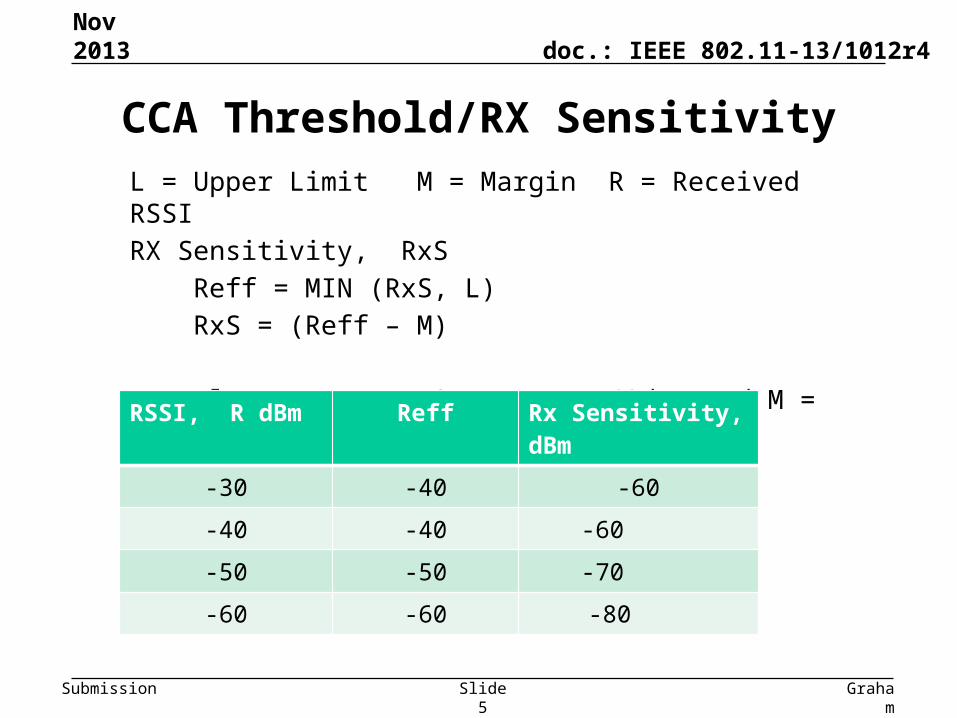
L = Upper Limit M = Margin R = Received RSSI
RX Sensitivity, RxS
Reff = MIN (RxS, L)
RxS = (Reff – M)
Example, FOR L = -40dBm and M = 20dB
CCA Threshold/RX Sensitivity
Nov 2013
Graham
Smith, DSP
Group
Slide 5
RSSI, R dBm Reff Rx Sensitivity, dBm
-30 -40 -60
-40 -40 -60
-50 -50 -70
-60 -60 -80
doc.: IEEE 802.11-13/1012r4
Submission
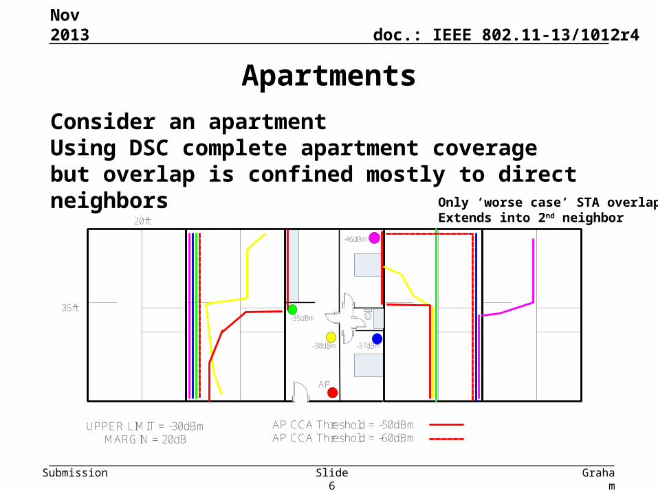
Apartments
Graham
Smith, DSP
Group
Slide 6
Nov 2013
AP
-46dBm
-35dBm
-30dBm -37dBm
UPPER LIMIT = -30dBmMARGIN = 20dB
AP CCA Threshold = -50dBmAP CCA Threshold = -60dBm
35ft
20ft
Consider an apartmentUsing DSC complete apartment coverage but overlap is confined mostly to direct neighbors
Only ‘worse case’ STA overlap Extends into 2nd neighbor
doc.: IEEE 802.11-13/1012r4
Submission
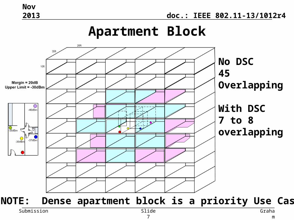
Apartment Block
Graham
Smith, DSP
Group
Slide 7
Nov 2013
No DSC 45 Overlapping
With DSC7 to 8 overlapping
NOTE: Dense apartment block is a priority Use Case
doc.: IEEE 802.11-13/1012r4
Submission
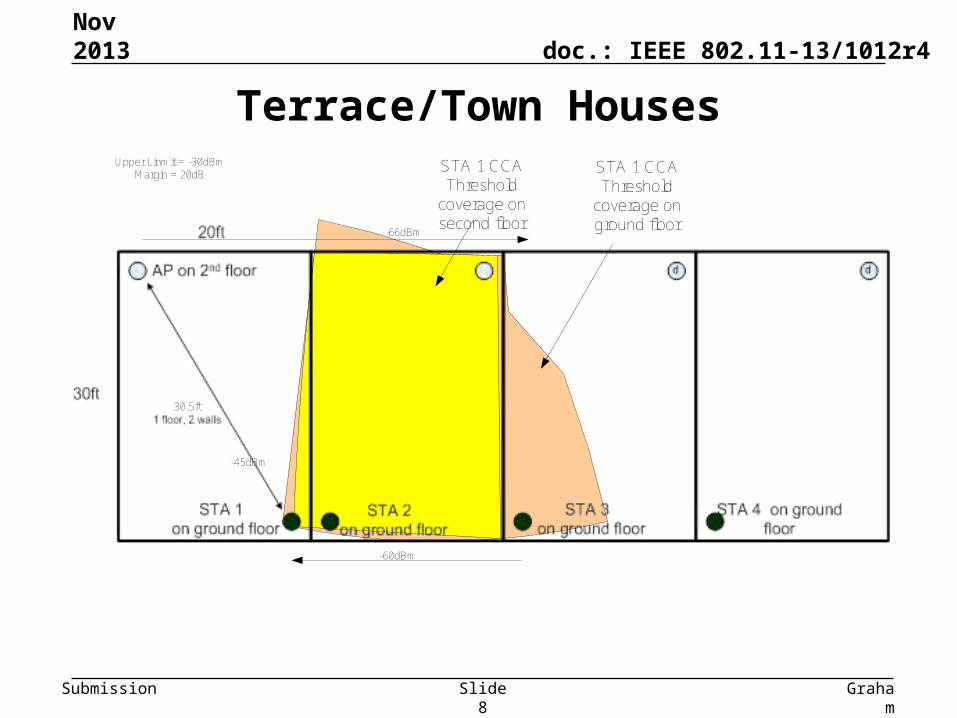
Terrace/Town Houses
Graham
Smith, DSP
Group
Slide 8
Nov 2013
-45dBm
-60dBm
-66dBm
Upper Linmit = -30dBmMargin = 20dB STA 1 CCA
Threshold coverage on ground floor
STA 1 CCA Threshold
coverage on second floor
30.5ft
doc.: IEEE 802.11-13/1012r4
Submission
Terrace/Town Houses
Graham
Smith, DSP
Group
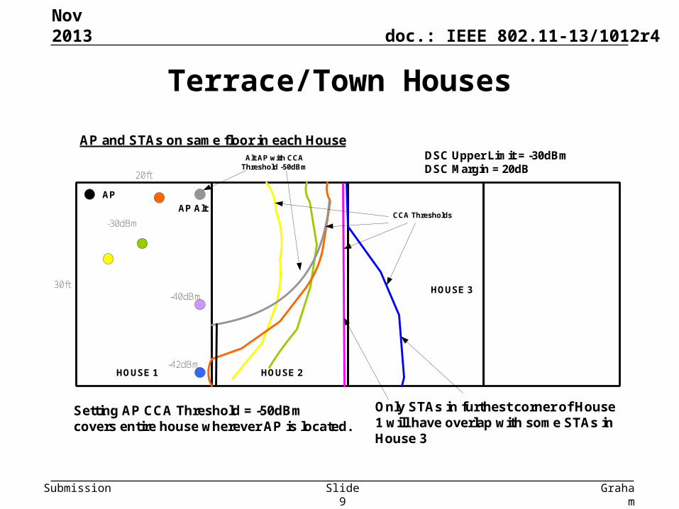
Slide 9
Nov 2013
20ft
30ft
-30dBm
-42dBm
-40dBm
Setting AP CCA Threshold = -50dBmcovers entire house wherever AP is located.
AP and STAs on same floor in each House
AP
AP Alt
Alt AP with CCA Threshold -50dBm
CCA Thresholds
Only STAs in furthest corner of House 1 will have overlap with some STAs in House 3
DSC Upper Limit = -30dBmDSC Margin = 20dB
HOUSE 1 HOUSE 2
HOUSE 3
doc.: IEEE 802.11-13/1012r4
Submission
Terrace/Townhouse
Graham
Smith, DSP
Group
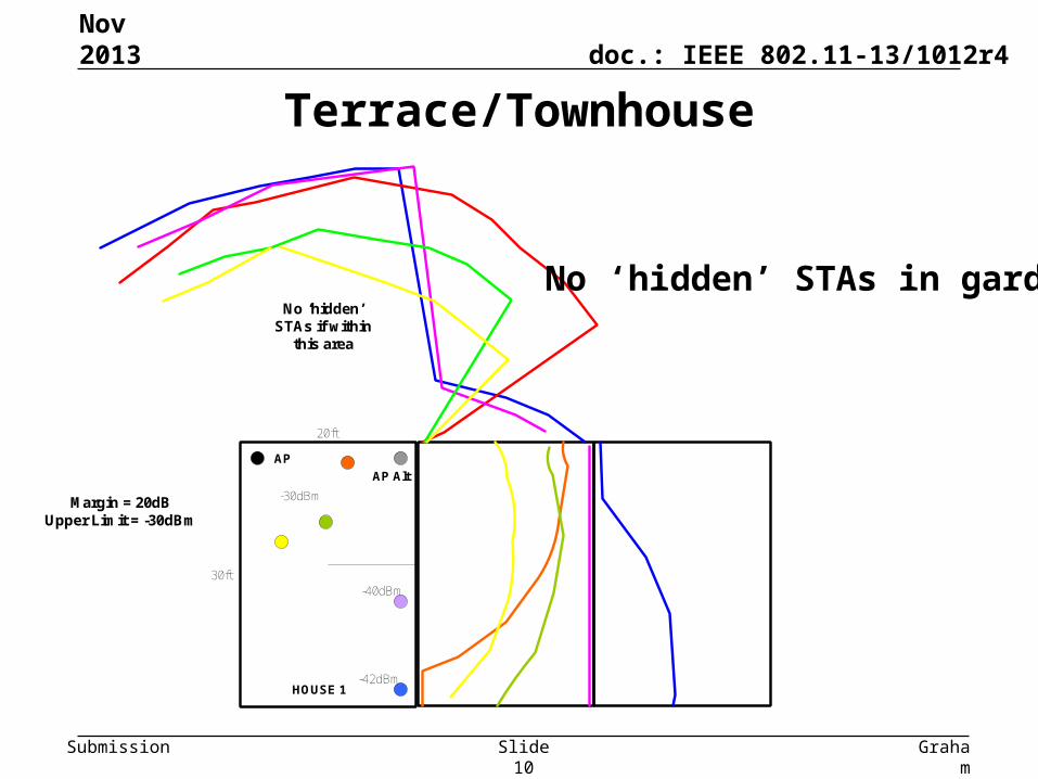
Slide 10
Nov 2013
20ft
30ft
-30dBm
-42dBm
-40dBm
AP
AP Alt
HOUSE 1
No ‘hidden’ STAs if within
this area
Margin = 20dBUpper Limit = -30dBm
No ‘hidden’ STAs in garden
doc.: IEEE 802.11-13/1012r4
Submission Graham
Smith, DSP
Group
Slide 11
Nov 2013
1
7
6
3
2 '
5
1 '
2
3 '
4 ' 5 '
AP 4
STA A
STA B
r
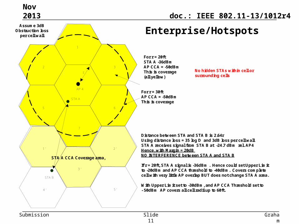
Assume 3dB Obstruction loss
per cell wall
Distance between STA and STA B is 2.64rUsing distance loss = 35 log D and 3dB loss per cell wallSTA A receives signal from STA B at -24.7 dBm rel. AP4Hence, with Margin = 20dB NO INTERFERENCE between STA A and STA B
If r = 20ft, STA A signal is -36dBm . Hence could set Upper Limit to -20dBm and AP CCA threshold to -40dBm. Covers complete cell with very little AP overlap BUT does not change STA A area.
With Upper Limit set to -30dBm, and AP CCA Threshold set to- 50dBm AP covers all cell radii up to 60ft.
For r = 20ftSTA A -36dBmAP CCA = -50dBmThis is coverage(all yellow)
For r = 30ftAP CCA = -50dBmThis is coverage
STA A CCA Coverage area,
No hidden STAs within cell or surrounding cells
Enterprise/Hotspots
doc.: IEEE 802.11-13/1012r4
Submission
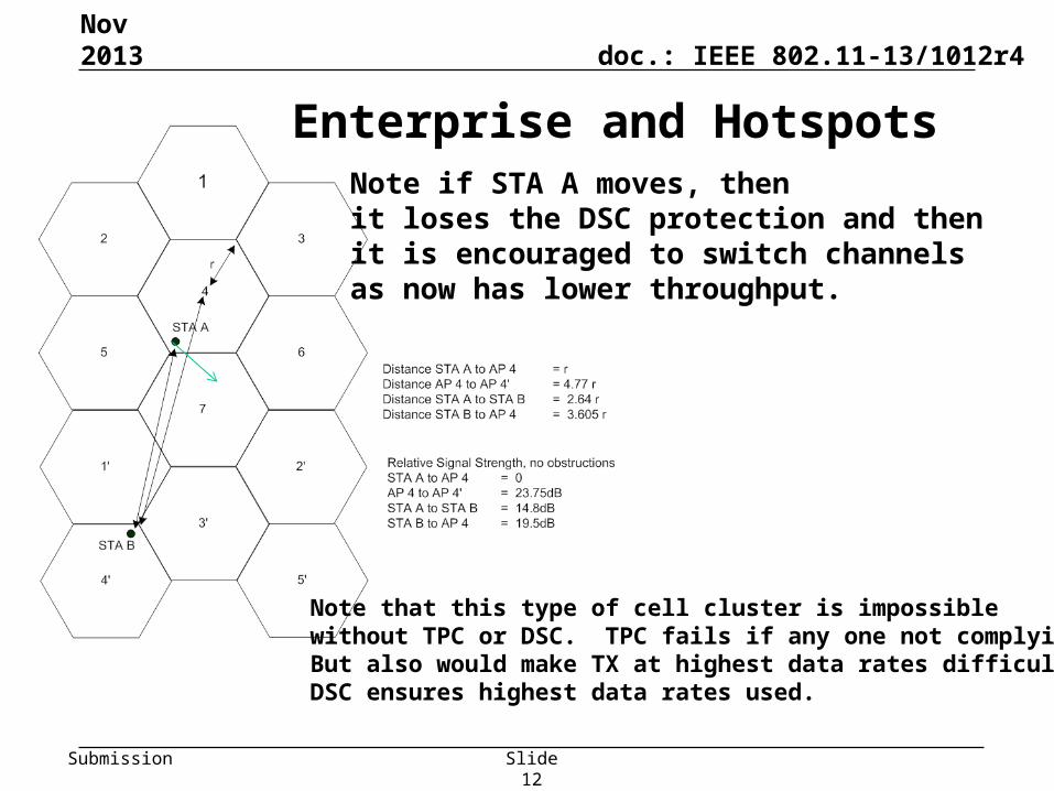
Enterprise and Hotspots
Graham Smith, DSP Group
Note if STA A moves, thenit loses the DSC protection and then it is encouraged to switch channels as now has lower throughput.
Note that this type of cell cluster is impossible without TPC or DSC. TPC fails if any one not complyingBut also would make TX at highest data rates difficult.DSC ensures highest data rates used.
Slide 12
Nov 2013
doc.: IEEE 802.11-13/1012r4
Submission
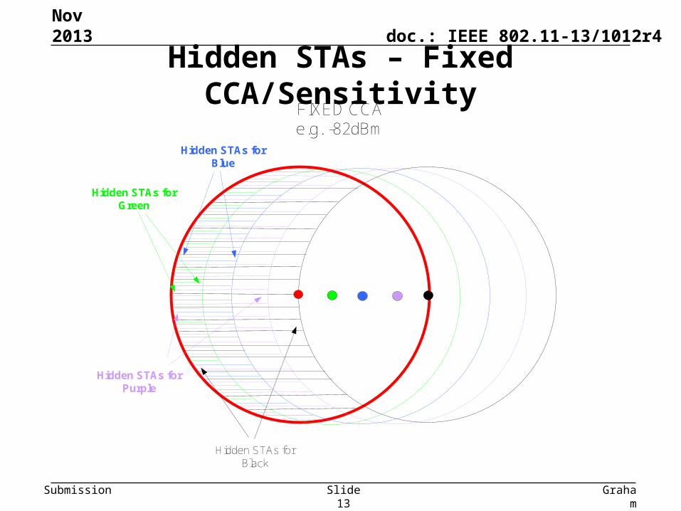
Hidden STAs – Fixed CCA/Sensitivity
Graham
Smith, DSP
Group
Slide 13
Nov 2013
FIXED CCA e.g. -82dBm
Hidden STAs for Green
Hidden STAs for Blue
Hidden STAs for Purple
Hidden STAs for Black
doc.: IEEE 802.11-13/1012r4
Submission
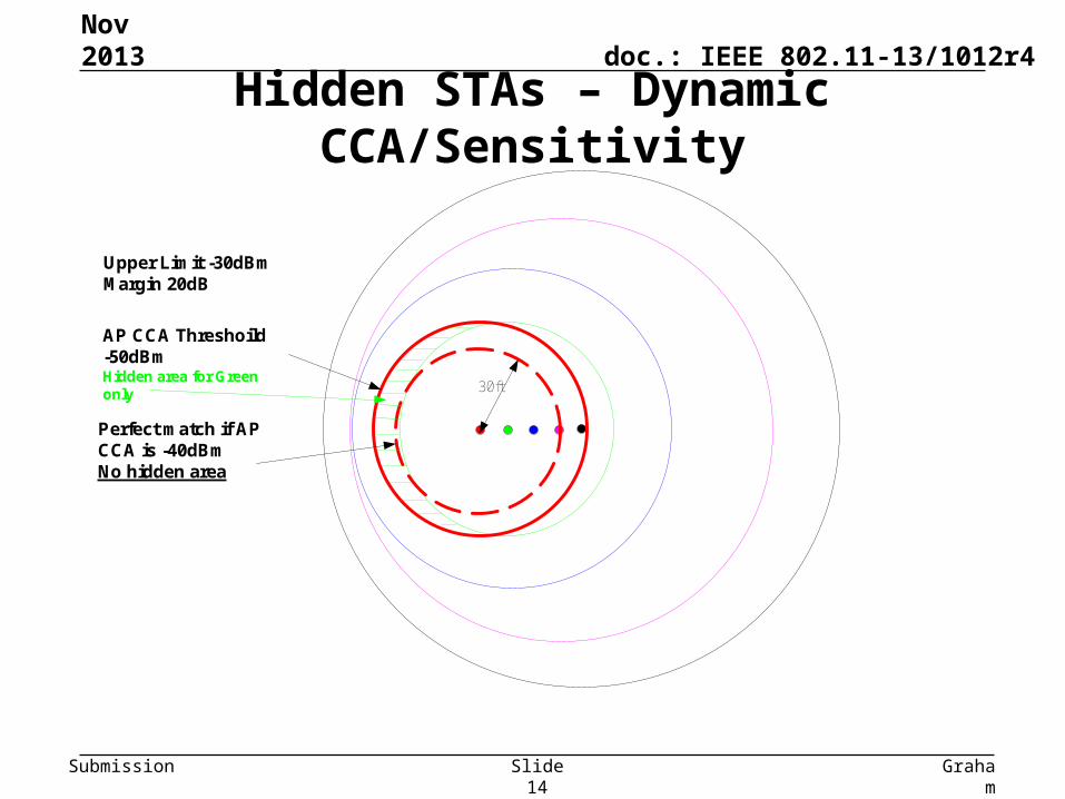
Hidden STAs – Dynamic CCA/Sensitivity
Graham
Smith, DSP
Group
Slide 14
Nov 2013
AP CCA Threshoild -50dBmHidden area for Green only
Perfect match if AP CCA is -40dBmNo hidden area
30ft
Upper Limit -30dBmMargin 20dB
doc.: IEEE 802.11-13/1012r4
Submission Graham
Smith, DSP
Group
Slide 15
Nov 2013
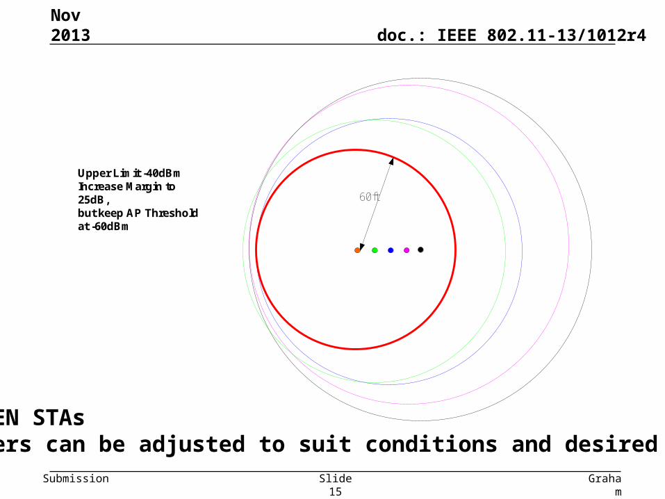
Upper Limit -40dBmIncrease Margin to 25dB, but keep AP Threshold at -60dBm
60ft
NO HIDDEN STAsParameters can be adjusted to suit conditions and desired coverage
doc.: IEEE 802.11-13/1012r4
Submission
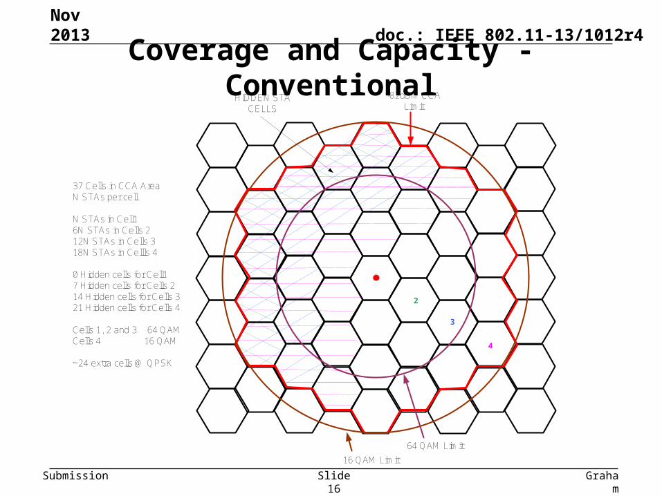
Coverage and Capacity - Conventional
Graham
Smith, DSP
Group
Slide 16
Nov 2013
2
3
4
64 QAM Limit
16 QAM Limit
HIDDEN STA CELLS
37 Cells in CCA AreaN STAs per cell
N STAs in Cell16N STAs in Cells 212N STAs in Cells 318N STAs in Cellls 4
0 Hidden cells for Cell17 Hidden cells for Cells 214 Hidden cells for Cells 321 Hidden cells for Cells 4
Cells 1, 2 and 3 64 QAMCells 4 16 QAM
~24 extra cells @ QPSK
-82dBm CCA Limit
doc.: IEEE 802.11-13/1012r4
Submission
Coverage and Capacity - DSC
Graham
Smith, DSP
Group
Slide 17
Nov 2013
1
7
2
3
4
4
5
6 3
5
4
6
3
7
6
3
7
3
2
5
1
2
6
1
3
7
1
4
2
1
5
3
1
6
4
1
7
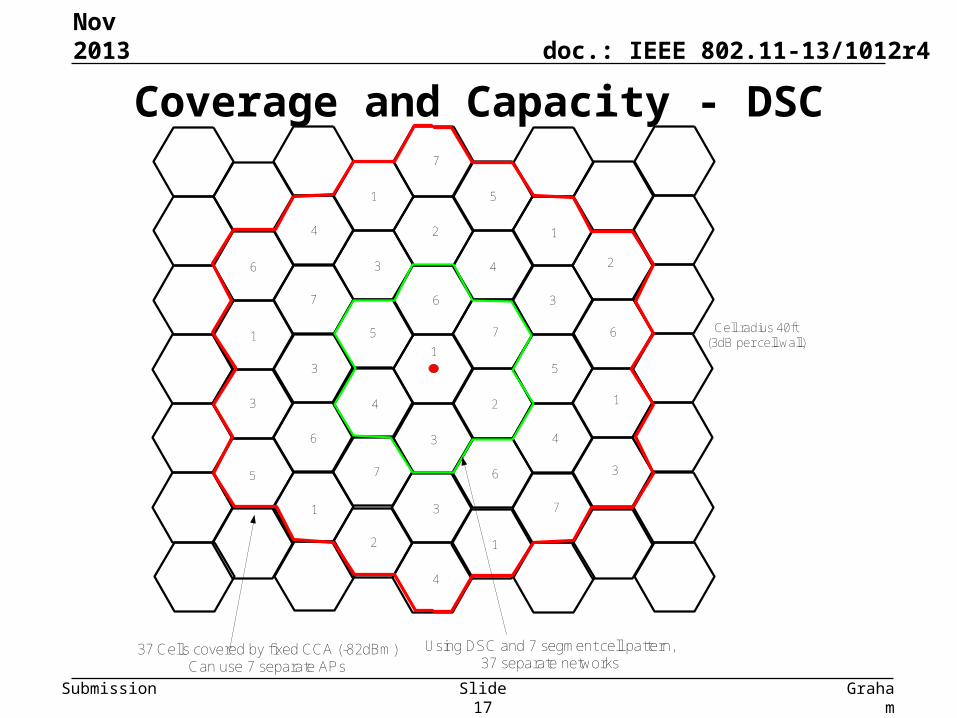
37 Cells covered by fixed CCA (-82dBm)Can use 7 separate APs
Using DSC and 7 segment cell pattern, 37 separate networks
Cell radius 40ft(3dB per cell wall)
doc.: IEEE 802.11-13/1012r4
Submission
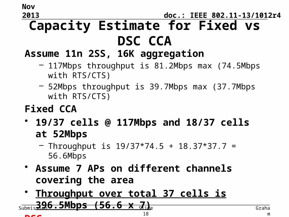
Assume 11n 2SS, 16K aggregation– 117Mbps throughput is 81.2Mbps max (74.5Mbps with RTS/CTS)– 52Mbps throughput is 39.7Mbps max (37.7Mbps with RTS/CTS)
Fixed CCA• 19/37 cells @ 117Mbps and 18/37 cells at 52Mbps
– Throughput is 19/37*74.5 + 18.37*37.7 = 56.6Mbps
• Assume 7 APs on different channels covering the area• Throughput over total 37 cells is 396.5Mbps (56.6 x 7)
DSC• All traffic at 117Mbs, • Throughput over 37 cells is 3004.8Mbps (81.2 x 37)
An improvement of 7.58 in capacity
Capacity Estimate for Fixed vs DSC CCA
Nov 2013
Graham
Smith, DSP
Group
Slide 18
doc.: IEEE 802.11-13/1012r4
Submission
The Margin needs to be set :
1. Large enough to provide adequate SNR– A STA at edge of CCA transmits at same time. The Margin is the
worse possible effective SNR (from a single simultaneous TX).
2. Large enough to account for sudden changes in reception of Beacon signal– If STA goes behind obstruction, RSSI will drop. If the drop is
higher than the Margin, then the AP Beacon is lost.
Suggested Margin is in the order of 20dB to 25dB.
See slide on Algorithm for setting Threshold
Setting the Margin
Nov 2013
Graham
Smith, DSP
Group
Slide 19
doc.: IEEE 802.11-13/1012r4
Submission
Flexibility
• Upper Limit and Margin can be adjusted to suit the application for an optimum result (AP can control)– 20dB Margin suggested as 20dB is approx required SNR for
higher data rates
• AP then sets its own Sensitivity or CCA – Based upon the Margin and Upper Limit
Graham Smith, DSP Group
Nov 2013
Slide 20
doc.: IEEE 802.11-13/1012r4
Submission
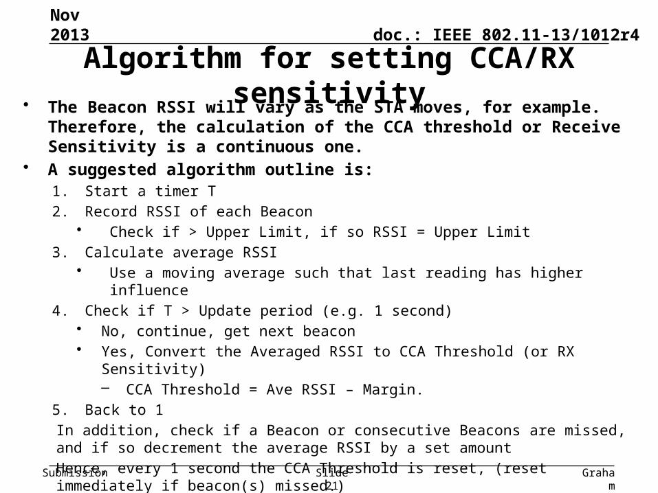
• The Beacon RSSI will vary as the STA moves, for example. Therefore, the calculation of the CCA threshold or Receive Sensitivity is a continuous one.
• A suggested algorithm outline is:1. Start a timer T
2. Record RSSI of each Beacon• Check if > Upper Limit, if so RSSI = Upper Limit
3. Calculate average RSSI • Use a moving average such that last reading has higher influence
4. Check if T > Update period (e.g. 1 second)• No, continue, get next beacon• Yes, Convert the Averaged RSSI to CCA Threshold (or RX Sensitivity)
– CCA Threshold = Ave RSSI – Margin.
5. Back to 1
In addition, check if a Beacon or consecutive Beacons are missed, and if so decrement the average RSSI by a set amount
Hence, every 1 second the CCA Threshold is reset, (reset immediately if beacon(s) missed.)
Algorithm for setting CCA/RX sensitivity
Nov 2013
Graham
Smith, DSP
Group
Slide 21
doc.: IEEE 802.11-13/1012r4
Submission
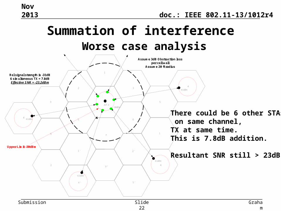
Summation of interference Worse case analysis
Nov 2013
Graham
Smith, DSP
Group
Slide 22
1
7
6
3
2 '
5
1 '
2
3 '
4 ' 5 '
AP 4
r
Rel signal strength is -31dB6 simultaneous TX = 7.8dBEffective SNR = -23.2dBm
-30dBm
2
6
3
-61dBm
-61dBm
4
1
5
4
-61dBm
4-61dBm
Upper Limit -30dBm
Assume 3dB Obstruction loss per cell wall
Assume 20 ft radius
There could be 6 other STAs, on same channel, TX at same time.This is 7.8dB addition.
Resultant SNR still > 23dB
doc.: IEEE 802.11-13/1012r4
Submission
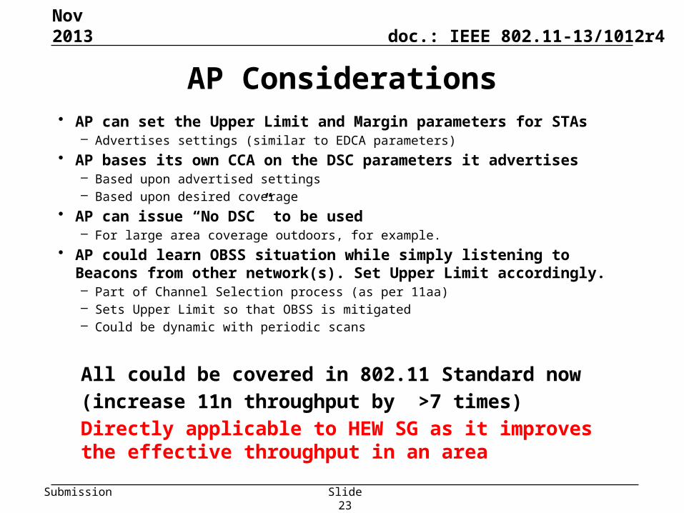
AP Considerations• AP can set the Upper Limit and Margin parameters for STAs
– Advertises settings (similar to EDCA parameters)
• AP bases its own CCA on the DSC parameters it advertises – Based upon advertised settings– Based upon desired coverage
• AP can issue “No DSC” to be used– For large area coverage outdoors, for example.
• AP could learn OBSS situation while simply listening to Beacons from other network(s). Set Upper Limit accordingly.– Part of Channel Selection process (as per 11aa)– Sets Upper Limit so that OBSS is mitigated– Could be dynamic with periodic scans
All could be covered in 802.11 Standard now
(increase 11n throughput by >7 times)
Directly applicable to HEW SG as it improves the effective throughput in an area
Graham Smith, DSP Group
Nov 2013
Slide 23
doc.: IEEE 802.11-13/1012r4
Submission
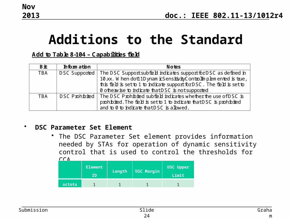
• DSC Parameter Set Element• The DSC Parameter Set element provides information needed by STAs for
operation of dynamic sensitivity control that is used to control the thresholds for CCA
Additions to the Standard
Nov 2013
Graham
Smith, DSP
Group
Slide 24
Element ID Length DSC MarginDSC Upper
Limit
octets 1 1 1 1
Add to Table 8-104 – Capabilities field
Bit Information Notes TBA DSC Supported The DSC Support subfield indicates support for DSC as defined in
10.xx. When dot11DynamicSensitivityControlImplemented is true, this field is set to 1 to indicate support for DSC. The field is set to 0 otherwise to indicate that DSC is not supported
TBA DSC Prohibited The DSC Prohibited subfield indicates whether the use of DSC is prohibited. The field is set to 1 to indicate that DSC is prohibited and to 0 to indicate that DSC is allowed.
doc.: IEEE 802.11-13/1012r4
Submission
Legacy STAs – No problem if in separate network
In each of the cases considered, Apartments, Houses, Cell Cluster, the legacy STA is UNAFFECTED• If the Legacy STA is in a separate network,
– If STA does not use DSC then:• If already started to TX it will complete (DSC STA can TX at same time) • If Legacy STA not started to TX it will hold off with CCA in the normal
fashion if DSC STA is TX – no difference
• DSC simply allows the STA using it to TX at the same time.
• Legacy network performance improves as need not wait so long for DSC network to TX (simultaneous TX)
Graham Smith, DSP Group
Nov 2013
Slide 25
doc.: IEEE 802.11-13/1012r4
Submission
Legacy STA – Same Network• If any STA is outside the coverage area set by the DSC, then it is at a
disadvantage as its TX could be stepped on by the DSC STA that is close to the AP. This is the same situation as “hidden STA”. – “Hidden STA” situation exists now so nothing new– Number of “Hidden STAs” reduced by DSC
• Note examples, possibility of hidden legacy or DSC STA is remote.• Consider also need to keep high data rates hence want to restrict range.
(Especially if using 40MHz channels or higher).
Finally• If outdoor and large area coverage required, DSC could be disabled by AP
IE.
Finally, Finally• There is a huge encouragement to enact DSC, unlike TPC.
Graham Smith, DSP Group
Nov 2013
Slide 26
doc.: IEEE 802.11-13/1012r4
Submission
In the examples studied:• DSC has a significant impact on area throughput
– Frequency reuse is increased by a significant factor– In cell cluster example, 2SS 20MHz BW total area throughput is
increased from 396.5Mbps to 3004.8Mbps (7 APs vs 37 APs)!
• DSC reduces or eliminates chance of hidden STAs• Legacy STAs are not disadvantaged• DSC is easy to implement and does not require every
network to comply, (as does TPC).
Conclusions
Nov 2013
Graham
Smith, DSP
Group
Slide 27
doc.: IEEE 802.11-13/1012r4
Submission
Discussion• We can expand the examples to specific enterprise, office environments.
– Network coverage is NOT simple circles. It is bounded by walls, floors, obstructions such that the propagation is not dB linear it suffers from jumps, e.g. 10dB per outside wall, 3 – 6dB inside walls.
– Network coverage can be made ‘cell like’ so as to improve the overall coverage.
• If only one network uses DSC it does not impact performance on other network – in fact it lessens impact as now TX simultaneously so other network does not need to wait so long.
• DSC Limit can be set to cover desired network area. – Correct choice of Upper Limit and Margin
• DSC can be combined with channel selection and mitigate OBSS. • DSC can improve overall Wi-Fi throughput in an area.• AP can control settings – see next slide
Graham Smith, DSP Group
Nov 2013
Slide 28
doc.: IEEE 802.11-13/1012r4
Submission
1. Do you think that DSC merits consideration for existing PHYs?– Yes – No
2. Do you think that DSC merits consideration for HEW?– Yes – No