31
DOCK PLANNING STANDARDS © 2013 Nova Technology International All Rights Reserved A DOCK PLANNING STANDARDS
| Date post: | 25-Mar-2018 |
| Category: |
Documents |
| Upload: | trinhkhanh |
| View: | 217 times |
| Download: | 3 times |

DOCK PLANNING STANDARDS
© 2013 Nova Technology InternationalAll Rights Reserved A
DOCK PLANNING STANDARDS

© 2013 Nova Technology InternationalAll Rights Reserved 1
TABLE OF CONTENTS
TABLE OF CONTENTSDESIGN THE SITE .....................................................................................................................................................................................................2
Safety ...................................................................................................................................................................................................................2Location of the Loading Docks ..................................................................................................................................................................2Plan On-site Traffic Patterns ........................................................................................................................................................................3Design the Apron Space ...............................................................................................................................................................................3Dock Approach ................................................................................................................................................................................................4Select the Loading Dock Configuration .................................................................................................................................................5
Inside/Outside Dock ..............................................................................................................................................................................6Open Dock ................................................................................................................................................................................................6Additional Dock Configurations .......................................................................................................................................................7
Determine the Number of Dock Positions .............................................................................................................................................8DESIGN THE LOADING DOCK .............................................................................................................................................................................8
Truck Specifications .......................................................................................................................................................................................8Sea Containers .............................................................................................................................................................................................. 10Underride Protection Bars ........................................................................................................................................................................ 10Set the Dock Height .................................................................................................................................................................................... 10Set the Loading Bay Widths ..................................................................................................................................................................... 11Select Dock Doors........................................................................................................................................................................................ 12Determine Door Sizes ................................................................................................................................................................................. 12
Widths ..................................................................................................................................................................................................... 12Heights .................................................................................................................................................................................................... 13
Design the Dock Interior ........................................................................................................................................................................... 13DOCKLEVELERS .................................................................................................................................................................................................... 14
Recessed Docklevelers ............................................................................................................................................................................... 14Mechanical Docklevelers .................................................................................................................................................................. 15Powered Docklevelers ....................................................................................................................................................................... 15
Edge-of-Dock Docklevelers ...................................................................................................................................................................... 16Specify the Correct Dockleveler ............................................................................................................................................................. 17
Length ..................................................................................................................................................................................................... 17Width ....................................................................................................................................................................................................... 18Lip Projection ........................................................................................................................................................................................ 19Load Capacity ....................................................................................................................................................................................... 19Activation System ............................................................................................................................................................................... 20Environmental Capability ................................................................................................................................................................. 20Optional Features ................................................................................................................................................................................ 20Benefits of Hydraulic and Air Bag Docklevelers over Mechanical Docklevelers........................................................... 20
Specifying the Elevating Dock ................................................................................................................................................................ 21BUMPERS ................................................................................................................................................................................................................. 21TRAILER RESTRAINTS ......................................................................................................................................................................................... 22
RIG-Dependent Restraints ........................................................................................................................................................................ 23Manual Wheel Chocks ................................................................................................................................................................................ 23
COMMUNICATION LIGHTS ............................................................................................................................................................................... 24DOCK RUN-OFF PROTECTION ........................................................................................................................................................................ 24
Gate Barriers .................................................................................................................................................................................................. 24Lip Barriers ...................................................................................................................................................................................................... 24
SEALING SYSTEMS ............................................................................................................................................................................................... 25Selection Criteria ......................................................................................................................................................................................... 25
Grade of Approach ............................................................................................................................................................................. 25Overhead Door Dimensions ............................................................................................................................................................ 25Dock Bumper Projection .................................................................................................................................................................. 26Dock Height .......................................................................................................................................................................................... 26Mounting Surface ............................................................................................................................................................................... 26
Compression Foam Dock Seals ............................................................................................................................................................... 26Truck Shelters ................................................................................................................................................................................................ 27Dock Lights..................................................................................................................................................................................................... 28
CONTACT NOVA ................................................................................................................................................................................................... 28
DOCK PLANNING STANDARDS
© 2013 Nova Technology InternationalAll Rights Reserved2
DESIGN THE SITE
SafetyThe Material Transfer Zone (MTZ), which acts as a bridge between the truck and warehouse, is a dangerous place where safety must be the most important consideration.
Safety is often considered only after a serious accident has occurred on the dock. To ensure the safety of dock attendants and product, consider all potential problems that could occur.
Consider security. Select the correct dock leveler for your facility. For additional safety at the loading dock, consider adding a vehicle restraint to help prevent unexpected trailer creep during the loading and unloading process.
Perform regular maintenance on the equipment. Equipment should be cleaned, lubricated and checked by a technician for longer product life and better productivity. Plan for maintenance of bumpers, lights, communication packages, and other loading dock accessories. Inventory these items regularly as wheel chocks can be swept away by plows and light bulbs will need to be replaced. Perform regular checks on the seals and shelters to make sure they do not leak. Infiltrating air will raise energy usage and may result in uncomfortable working conditions.
Protect your investment. Choose a barrier gate that prevents loading equipment from colliding with and damaging the dock doors. A barrier gate acts as a protective barrier against costly door damage.
Integrated control panels are useful when combining dock and overhead doors with other loading equipment. If you have combined a dockleveler with a trailer restraint and an automatic door, interconnecting each into a single control panel is an effective way to create a safer work environment.
Select the appropriate dockleveler capacity based on both the gross load and frequency of material handling devices in use at the site for optimal durability and safety. Also consider push button controlled powered docklevelers for ergonomic and ease of operation reasons as they put less physical stress on the dock attendants. If non-powered mechanical docklevelers are already present, consider upgrading the dockleveler to a push button controlled powered dockleveler with a hydraulic conversion kit.
Location of the Loading DocksLocate the loading docks to minimize forklift traffic inside the building. Rather than transporting individual pallets inside the building, unload trucks at multiple docks.
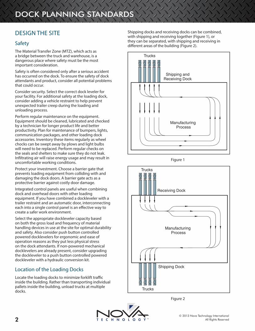
Shipping docks and receiving docks can be combined, with shipping and receiving together (Figure 1), or they can be separated, with shipping and receiving in different areas of the building (Figure 2).
Manufacturing Process
Shipping andReceiving Dock
Trucks
Figure 1
Manufacturing Process
Receiving Dock
Shipping Dock
Trucks
Trucks
Figure 2
DOCK PLANNING STANDARDS
© 2013 Nova Technology InternationalAll Rights Reserved 3
Choose the loading dock location based on the needs of the in-plant process. A combined dock works well in smaller buildings where shipping and receiving is infrequent. However, this design may increase in-plant traffic and travel distance.
A separated dock works well in buildings where the materials enter production in one part of the building and the production is completed elsewhere. This design minimizes transportation of materials inside the building.
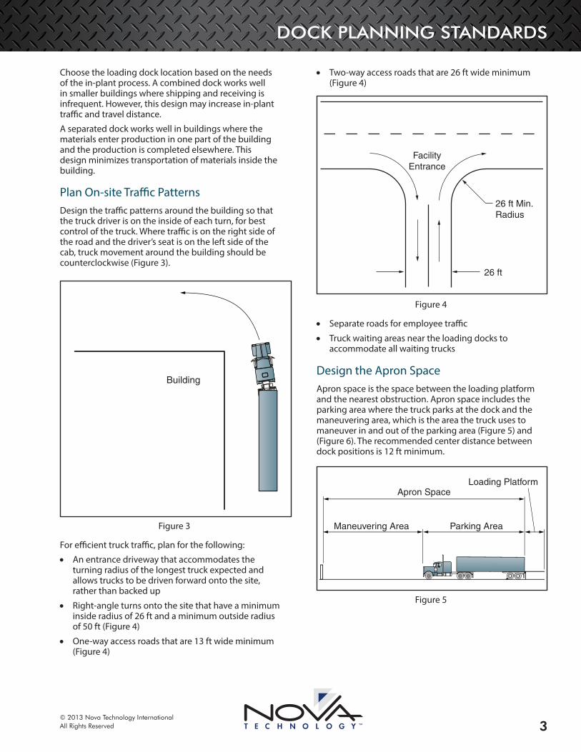
Plan On-site Traffic PatternsDesign the traffic patterns around the building so that the truck driver is on the inside of each turn, for best control of the truck. Where traffic is on the right side of the road and the driver’s seat is on the left side of the cab, truck movement around the building should be counterclockwise (Figure 3).
Building
Figure 3
For efficient truck traffic, plan for the following:
• An entrance driveway that accommodates the turning radius of the longest truck expected and allows trucks to be driven forward onto the site, rather than backed up
• Right-angle turns onto the site that have a minimum inside radius of 26 ft and a minimum outside radius of 50 ft (Figure 4)
• One-way access roads that are 13 ft wide minimum (Figure 4)
• Two-way access roads that are 26 ft wide minimum (Figure 4)
26 ft Min.Radius
26 ft
FacilityEntrance
Figure 4
• Separate roads for employee traffic
• Truck waiting areas near the loading docks to accommodate all waiting trucks
Design the Apron SpaceApron space is the space between the loading platform and the nearest obstruction. Apron space includes the parking area where the truck parks at the dock and the maneuvering area, which is the area the truck uses to maneuver in and out of the parking area (Figure 5) and (Figure 6). The recommended center distance between dock positions is 12 ft minimum.
Maneuvering Area
Apron Space
Parking Area
Loading Platform
Figure 5

DOCK PLANNING STANDARDS
© 2013 Nova Technology InternationalAll Rights Reserved4
12 ft Min.
Maneuvering Area
Apr
on S
pace
Loading Area
Figure 6
The minimum apron space required depends on the:
• Center line distances between the parked trucks at the dock
• Length of the trucks
• Steering geometry of the trucks
Less apron space is needed if the trailers will be parked with the tractors detached.
The minimum apron space for a typical 40 ft container rig is listed in Table 1.
Table 1
Center Distance 12 ft 13 ft 14 ft 16 ft 18 ftApron Space 120 ft 116 ft 113 ft 110 ft 108 ft
If expected trucks are longer than 40 ft, increase the apron space proportionately. For example, if the dock can accommodate 48 ft trailers, increase the apron space in the table by 20%. If the traffic pattern causes the driver to be on the outside of a turn, add 50 ft.
Always provide a concrete landing gear pad to support the trailer’s landing gear when the trailer is detached (Figure 7). The landing gear is about 33 ft from the back of the trailer on a standard 40 ft container chassis. The gear is about 11 ft from the back of the trailer on a 20 ft chassis. The pad should be wide enough to accommodate all expected types of trailers. It is helpful for the pad to extend all the way back to the loading platform. The pad should be designed to support two point loads of 25,000 lb each, 6 ft apart, to support a fully loaded trailer.
33 ft for40 ft Container
Landing Gear Pad
Figure 7
Dock ApproachThe maximum grade percentage from the loading dock to the vehicle is determined by the height of the dock (discussed in detail in Set the Dock Height on page 10). When using electric powered loading equipment, the maximum grade percentage is 10%. For gas or diesel powered loading equipment the maximum grade percentage is 15%. If these grade percentages are exceeded, damage to handling equipment and load spillage may result.
If the plant floor is at grade, or has a low grade, recess the truck parking area so that the trailer bed will be at about the same height as the plant floor (Figure 8). The parking area will slope down toward the dock. This slope should be 6% or less. If heavy loads are expected, the slope should not exceed 5%. If necessary, slope may be increased to an absolute maximum of 10%, and only for light loads. Steep slopes may cause loads to topple.
Figure 8
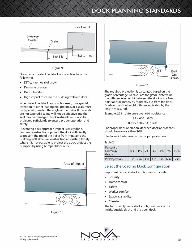
Always provide drainage for recessed parking areas. The area next to the building should slope slightly away from the building for a short distance of 1 to 3 ft (Figure 9). A short distance is preferable so that the position of the trailer’s rear axle will have less of an effect on the height of the trailer bed at the dock.
DOCK PLANNING STANDARDS
© 2013 Nova Technology InternationalAll Rights Reserved 5
Dock Height
Drain
DrivewayGrade
1 to 3 ft 1/2 to 1 in.
Figure 9
Drawbacks of a declined dock approach include the following:
• Difficult removal of snow
• Drainage of water
• Debris buildup
• High impact forces to the building wall and dock
When a declined dock approach is used, give special attention to other loading equipment. Dock seals must be tapered to match the angle of the trailer. If the seals are not tapered, sealing will not be effective and the seal may be damaged. Truck restraints must also be projected sufficiently to ensure proper operation and safety.
Preventing dock approach impact is easily done. For new constructions, project the dock sufficiently to prevent the top of the trailer from impacting the building wall. When reconstructing an existing facility where it is not possible to project the dock, project the bumpers by using bumper block outs.
Area of Impact
Figure 10
BuiltOut
Blocks
Figure 11
The required projection is calculated based on the grade percentage. To calculate the grade, determine the difference in height between the dock and a fixed point approximately 50 ft directly out from the dock. Grade equals the height difference divided by the length measured.
Example: 22 in. difference over 660 in. distance
22 ÷ 660 = 0.03
0.03 × 100 = 3% grade
For proper dock operation, declined dock approaches should be no more than 10%.
Use Table 2 to determine the proper projection.
Table 2
Percent of Driveway Grade
0% 1% 2% 3% 4% 5% 10%
Pit Projection 0 in. 2 in. 3 in. 4 in. 5 in. 6 in. 12 in.
Select the Loading Dock ConfigurationImportant factors in dock configuration include:
• Security
• Traffic control
• Safety
• Worker comfort
• Space availability
• Climate
The two main types of dock configurations are the inside/outside dock and the open dock.
DOCK PLANNING STANDARDS
© 2013 Nova Technology InternationalAll Rights Reserved6
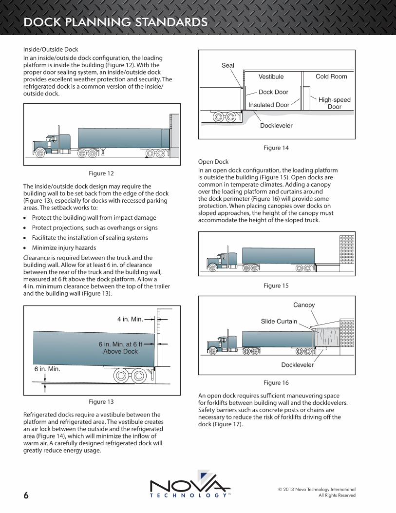
Inside/Outside DockIn an inside/outside dock configuration, the loading platform is inside the building (Figure 12). With the proper door sealing system, an inside/outside dock provides excellent weather protection and security. The refrigerated dock is a common version of the inside/outside dock.
Figure 12
The inside/outside dock design may require the building wall to be set back from the edge of the dock (Figure 13), especially for docks with recessed parking areas. The setback works to:
• Protect the building wall from impact damage
• Protect projections, such as overhangs or signs
• Facilitate the installation of sealing systems
• Minimize injury hazards
Clearance is required between the truck and the building wall. Allow for at least 6 in. of clearance between the rear of the truck and the building wall, measured at 6 ft above the dock platform. Allow a 4 in. minimum clearance between the top of the trailer and the building wall (Figure 13).
6 in. Min. at 6 ftAbove Dock
4 in. Min.
6 in. Min.
Figure 13
Refrigerated docks require a vestibule between the platform and refrigerated area. The vestibule creates an air lock between the outside and the refrigerated area (Figure 14), which will minimize the inflow of warm air. A carefully designed refrigerated dock will greatly reduce energy usage.
Seal
Dock DoorHigh-speed
DoorInsulated Door
Dockleveler
Vestibule Cold Room
Figure 14
Open DockIn an open dock configuration, the loading platform is outside the building (Figure 15). Open docks are common in temperate climates. Adding a canopy over the loading platform and curtains around the dock perimeter (Figure 16) will provide some protection. When placing canopies over docks on sloped approaches, the height of the canopy must accommodate the height of the sloped truck.
Figure 15
Slide Curtain
Dockleveler
Canopy
Figure 16
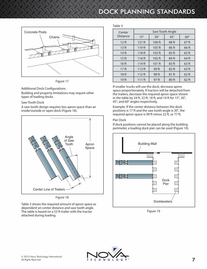
An open dock requires sufficient maneuvering space for forklifts between building wall and the docklevelers. Safety barriers such as concrete posts or chains are necessary to reduce the risk of forklifts driving off the dock (Figure 17).
DOCK PLANNING STANDARDS
© 2013 Nova Technology InternationalAll Rights Reserved 7
Concrete Posts
Chains
Figure 17
Additional Dock ConfigurationsBuilding and property limitations may require other types of loading docks.
Saw-Tooth DockA saw-tooth design requires less apron space than an inside/outside or open dock (Figure 18).
Center Line of Trailers
ApronSpace
Angleof SawTooth
Figure 18
Table 3 shows the required amount of apron space as dependent on center distance and saw tooth angle. The table is based on a 53 ft trailer with the tractor attached during loading.
Table 3
Center Distance
Saw-Tooth Angle
15° 30° 45° 60°
12 ft 121 ft 106 ft 88 ft 67 ft
13 ft 119 ft 105 ft 86 ft 66 ft
14 ft 118 ft 103 ft 85 ft 65 ft
15 ft 116 ft 102 ft 84 ft 64 ft
16 ft 114 ft 101 ft 83 ft 63 ft
17 ft 113 ft 99 ft 82 ft 63 ft
18 ft 112 ft 98 ft 81 ft 62 ft
19 ft 111 ft 97 ft 80 ft 62 ft
If smaller trucks will use the dock, decrease apron space proportionately. If tractors will be detached from the trailers, decrease the required apron space shown in the table by 24 ft, 22 ft, 18 ft, and 14 ft for 15°, 30°, 45°, and 60° angles respectively.
Example: If the center distance between the dock positions is 17 ft and the saw tooth angle is 30°, the required apron space is 99 ft minus 22 ft, or 77 ft.
Pier DockIf dock positions cannot be placed along the building perimeter, a loading dock pier can be used (Figure 19).
DockPier
Docklevelers
Building Wall
Figure 19
DOCK PLANNING STANDARDS
© 2013 Nova Technology InternationalAll Rights Reserved8
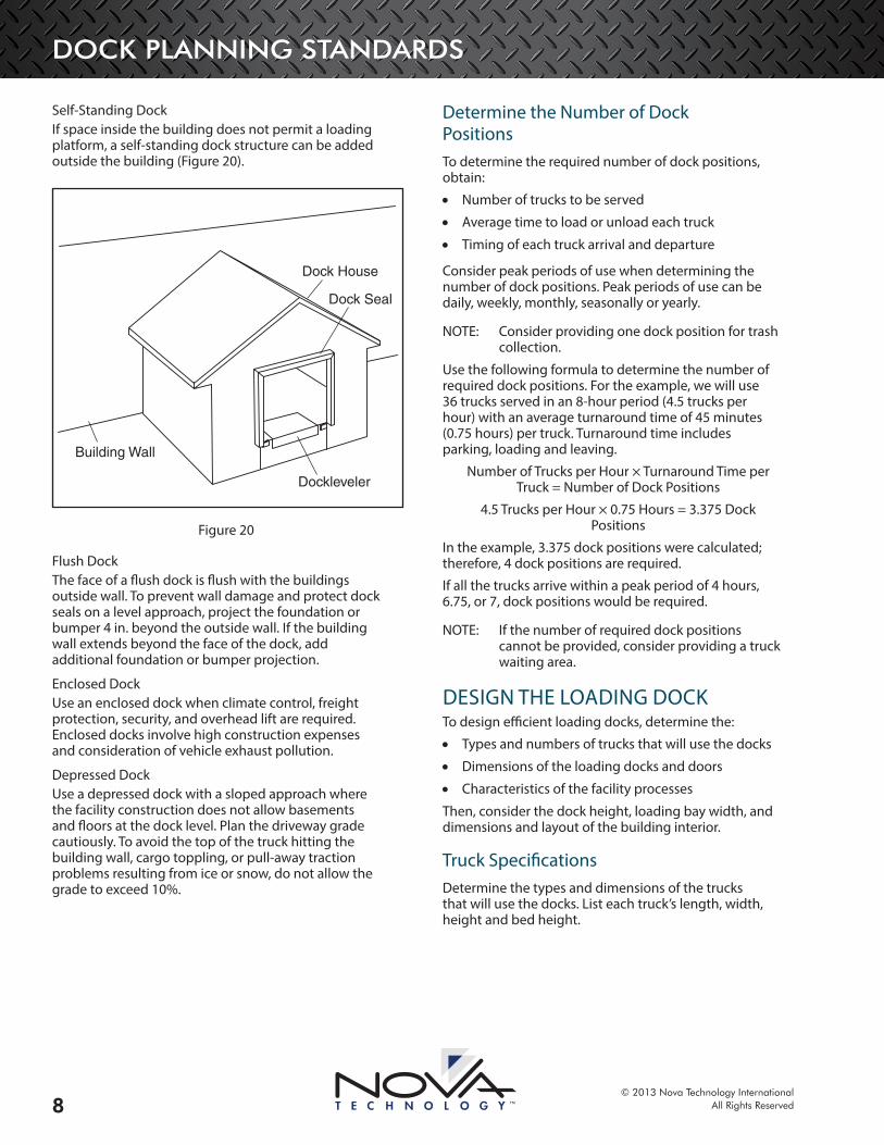
Self-Standing DockIf space inside the building does not permit a loading platform, a self-standing dock structure can be added outside the building (Figure 20).
Building Wall
Dockleveler
Dock House
Dock Seal
Figure 20
Flush Dock The face of a flush dock is flush with the buildings outside wall. To prevent wall damage and protect dock seals on a level approach, project the foundation or bumper 4 in. beyond the outside wall. If the building wall extends beyond the face of the dock, add additional foundation or bumper projection.
Enclosed DockUse an enclosed dock when climate control, freight protection, security, and overhead lift are required. Enclosed docks involve high construction expenses and consideration of vehicle exhaust pollution.
Depressed DockUse a depressed dock with a sloped approach where the facility construction does not allow basements and floors at the dock level. Plan the driveway grade cautiously. To avoid the top of the truck hitting the building wall, cargo toppling, or pull-away traction problems resulting from ice or snow, do not allow the grade to exceed 10%.
Determine the Number of Dock PositionsTo determine the required number of dock positions, obtain:
• Number of trucks to be served
• Average time to load or unload each truck
• Timing of each truck arrival and departure
Consider peak periods of use when determining the number of dock positions. Peak periods of use can be daily, weekly, monthly, seasonally or yearly.
OTE:N Consider providing one dock position for trash collection.
Use the following formula to determine the number of required dock positions. For the example, we will use 36 trucks served in an 8-hour period (4.5 trucks per hour) with an average turnaround time of 45 minutes (0.75 hours) per truck. Turnaround time includes parking, loading and leaving.
Number of Trucks per Hour × Turnaround Time per Truck = Number of Dock Positions
4.5 Trucks per Hour × 0.75 Hours = 3.375 Dock Positions
In the example, 3.375 dock positions were calculated; therefore, 4 dock positions are required.
If all the trucks arrive within a peak period of 4 hours, 6.75, or 7, dock positions would be required.
OTE:N If the number of required dock positions cannot be provided, consider providing a truck waiting area.
DESIGN THE LOADING DOCKTo design efficient loading docks, determine the:
• Types and numbers of trucks that will use the docks
• Dimensions of the loading docks and doors
• Characteristics of the facility processes
Then, consider the dock height, loading bay width, and dimensions and layout of the building interior.
Truck SpecificationsDetermine the types and dimensions of the trucks that will use the docks. List each truck’s length, width, height and bed height.
DOCK PLANNING STANDARDS
© 2013 Nova Technology InternationalAll Rights Reserved 9
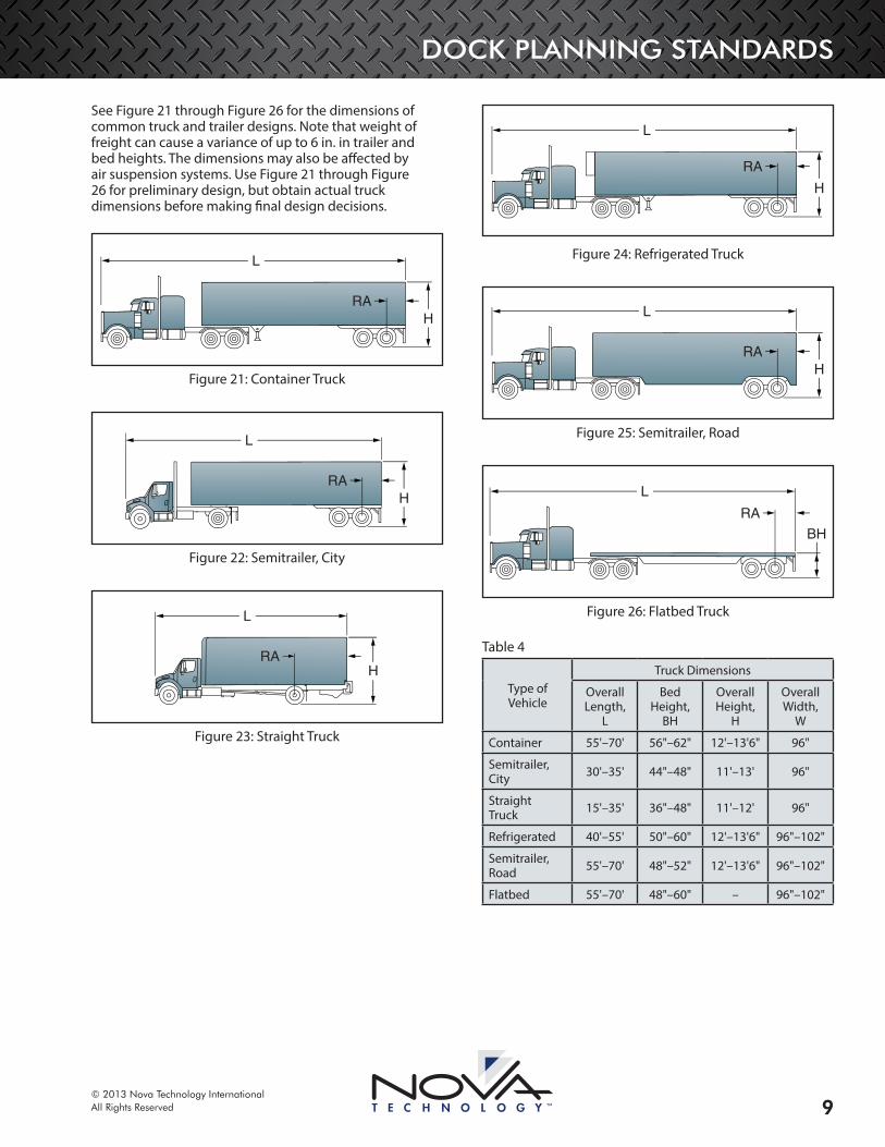
See Figure 21 through Figure 26 for the dimensions of common truck and trailer designs. Note that weight of freight can cause a variance of up to 6 in. in trailer and bed heights. The dimensions may also be affected by air suspension systems. Use Figure 21 through Figure 26 for preliminary design, but obtain actual truck dimensions before making final design decisions.
L
HRA
Figure 21: Container Truck
L
HRA
Figure 22: Semitrailer, City
L
HRA
Figure 23: Straight Truck
L
H
RA
Figure 24: Refrigerated Truck
L
HRA
Figure 25: Semitrailer, Road
L
BH
RA
Figure 26: Flatbed Truck
Table 4
Type of Vehicle
Truck Dimensions
Overall Length,
L
Bed Height,
BH
Overall Height,
H
Overall Width,
W
Container 55'–70' 56"–62" 12'–13'6" 96"
Semitrailer, City 30'–35' 44"–48" 11'–13' 96"
Straight Truck 15'–35' 36"–48" 11'–12' 96"
Refrigerated 40'–55' 50"–60" 12'–13'6" 96"–102"
Semitrailer, Road 55'–70' 48"–52" 12'–13'6" 96"–102"
Flatbed 55'–70' 48"–60" – 96"–102"
DOCK PLANNING STANDARDS
© 2013 Nova Technology InternationalAll Rights Reserved10
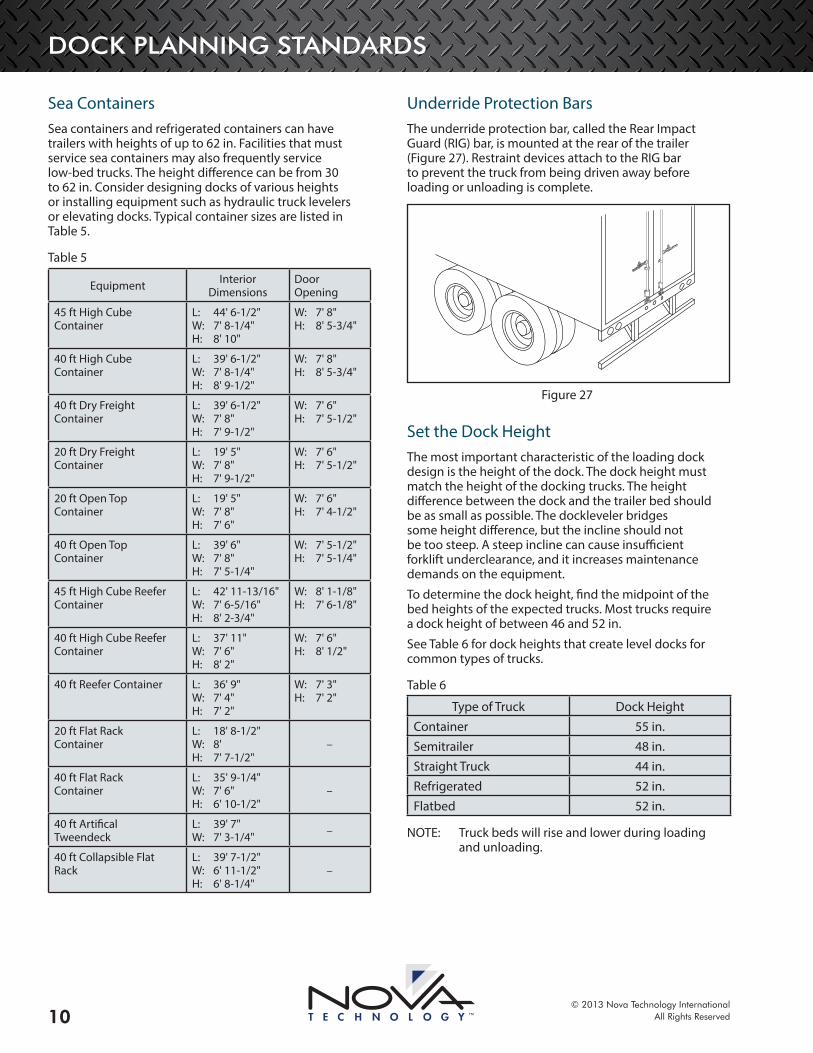
Sea ContainersSea containers and refrigerated containers can have trailers with heights of up to 62 in. Facilities that must service sea containers may also frequently service low-bed trucks. The height difference can be from 30 to 62 in. Consider designing docks of various heights or installing equipment such as hydraulic truck levelers or elevating docks. Typical container sizes are listed in Table 5.
Table 5
Equipment Interior Dimensions
Door Opening
45 ft High Cube Container
L: 44' 6-1/2" W: 7' 8-1/4" H: 8' 10"
W: 7' 8" H: 8' 5-3/4"
40 ft High Cube Container
L: 39' 6-1/2" W: 7' 8-1/4" H: 8' 9-1/2"
W: 7' 8" H: 8' 5-3/4"
40 ft Dry Freight Container
L: 39' 6-1/2" W: 7' 8" H: 7' 9-1/2"
W: 7' 6" H: 7' 5-1/2"
20 ft Dry Freight Container
L: 19' 5" W: 7' 8" H: 7' 9-1/2"
W: 7' 6" H: 7' 5-1/2"
20 ft Open Top Container
L: 19' 5" W: 7' 8" H: 7' 6"
W: 7' 6" H: 7' 4-1/2"
40 ft Open Top Container
L: 39' 6" W: 7' 8" H: 7' 5-1/4"
W: 7' 5-1/2" H: 7' 5-1/4"
45 ft High Cube Reefer Container
L: 42' 11-13/16" W: 7' 6-5/16" H: 8' 2-3/4"
W: 8' 1-1/8" H: 7' 6-1/8"
40 ft High Cube Reefer Container
L: 37' 11" W: 7' 6" H: 8' 2"
W: 7' 6" H: 8' 1/2"
40 ft Reefer Container L: 36' 9" W: 7' 4" H: 7' 2"
W: 7' 3" H: 7' 2"
20 ft Flat Rack Container
L: 18' 8-1/2" W: 8' H: 7' 7-1/2"
–
40 ft Flat Rack Container
L: 35' 9-1/4" W: 7' 6" H: 6' 10-1/2"
–
40 ft Artifical Tweendeck
L: 39' 7" W: 7' 3-1/4" –
40 ft Collapsible Flat Rack
L: 39' 7-1/2" W: 6' 11-1/2" H: 6' 8-1/4"
–
Underride Protection BarsThe underride protection bar, called the Rear Impact Guard (RIG) bar, is mounted at the rear of the trailer (Figure 27). Restraint devices attach to the RIG bar to prevent the truck from being driven away before loading or unloading is complete.
Figure 27
Set the Dock HeightThe most important characteristic of the loading dock design is the height of the dock. The dock height must match the height of the docking trucks. The height difference between the dock and the trailer bed should be as small as possible. The dockleveler bridges some height difference, but the incline should not be too steep. A steep incline can cause insufficient forklift underclearance, and it increases maintenance demands on the equipment.
To determine the dock height, find the midpoint of the bed heights of the expected trucks. Most trucks require a dock height of between 46 and 52 in.
See Table 6 for dock heights that create level docks for common types of trucks.
Table 6
Type of Truck Dock HeightContainer 55 in.Semitrailer 48 in.Straight Truck 44 in.Refrigerated 52 in.Flatbed 52 in.
OTE:N Truck beds will rise and lower during loading and unloading.
DOCK PLANNING STANDARDS
© 2013 Nova Technology InternationalAll Rights Reserved 11
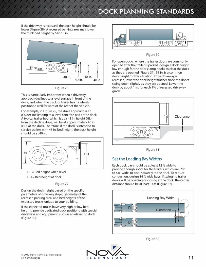
If the driveway is recessed, the dock height should be lower (Figure 28). A recessed parking area may lower the truck bed height by 6 to 10 in.
48 in.
8° Slope
48 in.40 in.
40 in.
Figure 28
This is particularly important when a driveway approach declines to a level surface in front of the dock, and when the truck or trailer has its wheels positioned well forward of the rear of the vehicle.
For example, in Figure 29, the drive approach is an 8% decline leading to a level concrete pad at the dock. A typical trailer bed, which is at a 48 in. height (HL) from the decline drive, will be at approximately 40 in. (HD) at the dock. Therefore, if the dock is intended to service trailers with 48 in. bed height, the dock height should be at 40 in.
HDHL
HL = Bed height when level
HD = Bed height at dock
Figure 29
Design the dock height based on the specific parameters of driveway slope, geometry of the recessed parking area, and bed heights of the expected trucks unique to your building.
If the expected trucks have very high or low bed heights, provide dedicated dock positions with special driveways and equipment, such as an elevating dock (Figure 30).
Figure 30
For open docks, where the trailer doors are commonly opened after the trailer is parked, design a dock height low enough for the door clamp hooks to clear the dock as they are opened (Figure 31). 51 in. is a common dock height for this situation. If the driveway is recessed, lower the dock height further since the doors swing down slightly as they are opened. Lower the dock by about 1 in. for each 1% of recessed driveway grade.
Clearance
Figure 31
Set the Loading Bay WidthsEach truck bay should be at least 12 ft wide to provide enough space for the trailers, which are 8'0" to 8'6" wide, to back squarely to the dock. To reduce congestion, design 14 ft wide bays. If swinging trailer doors will be opening or closing at the dock, the center distance should be at least 14 ft (Figure 32).
Clearance
Loading Bay Width
Figure 32

DOCK PLANNING STANDARDS
© 2013 Nova Technology InternationalAll Rights Reserved12
Select Dock DoorsA dock door is required for inside/outside loading docks. The most commonly installed doors are manually operated and are either an overhead sectional door or a roller door. A sectional door is smoother and quieter than a roller door because of rollers that run inside of tracks. Other advantages of a sectional door are:
• They are thicker and stronger than a roller door
• They can be insulated
OTE:N Install door track protectors to protect the door tracks.
Common dock door dimensions are 8'0" in width with 8 ft, 9 ft or 10 ft heights. Consider extending the door 13 ft to 14 ft above the driveway and a minimum of 8'6" wide if full access to the truck’s interior is required. Dock doors dimensions are determined by:
• Type of trucks being serviced
• Sealing system
• Environmental concerns
Determine Door Sizes
OTE:N The maximum trailer size limits are 8'6" wide x 13'6" high (varies by state). With a special permit, a flatbed may exceed the maximum width.
WidthsDetermine the door sizes along with selecting the sealing system. Keep doors as small as possible – usually narrower than 8 ft – in temperature-controlled docks, where energy is lost through doors. Space the doors 12 ft apart to accommodate most trucks, sealing systems, and communication light systems.
Dock doors narrower than 8'0" are commonly installed with compressed foam dock seals for temperature control of refrigerated operations.
9 ft wide doors should be used to service 8'6" wide trailers. Side-by-side palletizing is simplified, potential for product damage is reduced, and oversized loads can be serviced.
The doors should be between 8'6" and 9'0" wide to allow for trucks to park off-center. A 10 ft wide door can be designed for oversized loads. Note that wider doors require more building space, which may not be available.
OTE:N Compression of seals may reduce the effective width and full access to trailer.
8 ft
7' 6"
Figure 33
8' 6"
8 ft
Figure 34
DOCK PLANNING STANDARDS
© 2013 Nova Technology InternationalAll Rights Reserved 13
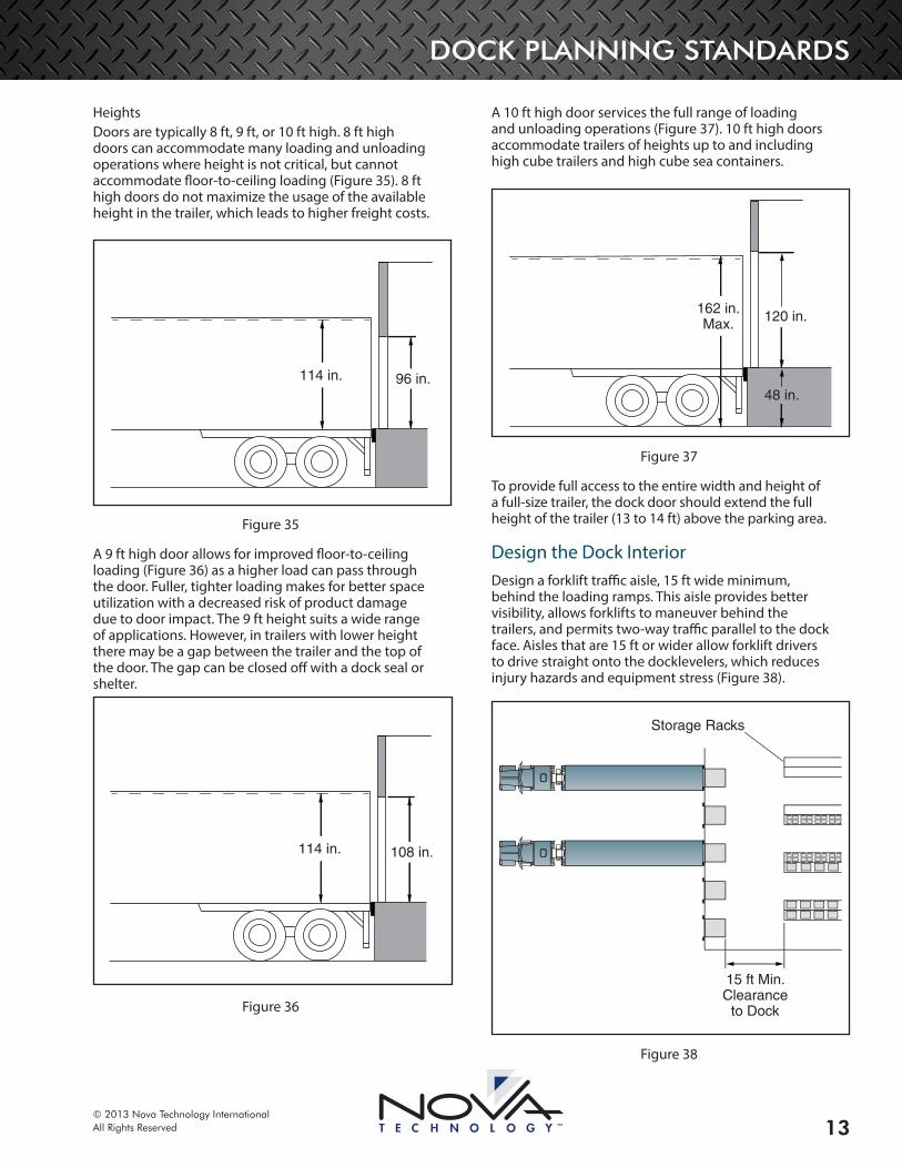
HeightsDoors are typically 8 ft, 9 ft, or 10 ft high. 8 ft high doors can accommodate many loading and unloading operations where height is not critical, but cannot accommodate floor-to-ceiling loading (Figure 35). 8 ft high doors do not maximize the usage of the available height in the trailer, which leads to higher freight costs.
114 in. 96 in.
Figure 35
A 9 ft high door allows for improved floor-to-ceiling loading (Figure 36) as a higher load can pass through the door. Fuller, tighter loading makes for better space utilization with a decreased risk of product damage due to door impact. The 9 ft height suits a wide range of applications. However, in trailers with lower height there may be a gap between the trailer and the top of the door. The gap can be closed off with a dock seal or shelter.
114 in. 108 in.
Figure 36
A 10 ft high door services the full range of loading and unloading operations (Figure 37). 10 ft high doors accommodate trailers of heights up to and including high cube trailers and high cube sea containers.
120 in. 162 in.Max.
48 in.
Figure 37
To provide full access to the entire width and height of a full-size trailer, the dock door should extend the full height of the trailer (13 to 14 ft) above the parking area.
Design the Dock InteriorDesign a forklift traffic aisle, 15 ft wide minimum, behind the loading ramps. This aisle provides better visibility, allows forklifts to maneuver behind the trailers, and permits two-way traffic parallel to the dock face. Aisles that are 15 ft or wider allow forklift drivers to drive straight onto the docklevelers, which reduces injury hazards and equipment stress (Figure 38).
Storage Racks
15 ft Min.Clearance
to Dock
Figure 38
DOCK PLANNING STANDARDS
© 2013 Nova Technology InternationalAll Rights Reserved14
Put restrictions into place that deter forklift drivers from driving parallel to the dock face (Figure 39), which can result in collisions with forklifts backing out of trailers.
DockLeveler
Figure 39
DOCKLEVELERSA dockleveler forms a ramp to bridge the distance between the dock and truck. It must be able to compensate for the up-and-down movement of the trailer during loading and unloading. A dockleveler must support extremely heavy loads, service a wide range of truck heights, and compensate for tilted trucks. A dockleveler includes a ramp and a lip. The ramp is hinged at along its rear edge, and the lip is hinged at the front of the ramp. To use a dockleveler, raise the ramp. The lip will swing out. With the lip extended, lower the ramp until the lip rests on the truck.
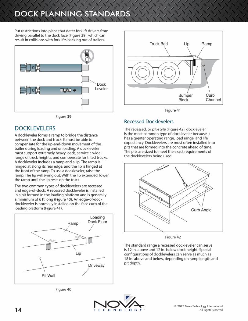
The two common types of docklevelers are recessed and edge-of-dock. A recessed dockleveler is installed in a pit formed in the loading platform and is generally a minimum of 6 ft long (Figure 40). An edge-of-dock dockleveler is normally installed on the face curb of the loading platform (Figure 41).
Driveway
Pit Wall
Lip
Ramp
LoadingDock Floor
Figure 40
Truck Bed Lip Ramp
BumperBlock
CurbChannel
Figure 41
Recessed DocklevelersThe recessed, or pit-style (Figure 42), dockleveler is the most common type of dockleveler because it has a greater operating range, load range, and life expectancy. Docklevelers are most often installed into pits that are formed into the concrete ahead of time. The pits are sized to meet the exact requirements of the docklevelers being used.
Curb Angle
Figure 42
The standard range a recessed dockleveler can serve is 12 in. above and 12 in. below dock height. Special configurations of docklevelers can serve as much as 18 in. above and below, depending on ramp length and pit depth.
DOCK PLANNING STANDARDS
© 2013 Nova Technology InternationalAll Rights Reserved 15
Recessed docklevelers are available with a spring-loaded mechanical activation system or powered with a push-button activation system. Powered, push-button models are easier to operate and are activated by either an air or hydraulic system. Although the initial cost of a mechanical dockleveler is less than a powered dockleveler, the long-term operating cost for a powered dockleveler can be lower.
Mechanical DocklevelersMechanical docklevelers are suitable for most applications. Mechanical docklevelers do not require expensive electrical provisions and hookups. They will operate even during power failures.
A mechanical, spring-loaded dockleveler (Figure 43) is upwardly biased with a spring and linkage system. It is held down by a releasable holdown device. To raise the ramp, pull the release chain connected to the holdown mechanism. Then, walk out on the ramp to force it down onto the truck bed. Once on the truck bed, the ratchet mechanism re-engages to prevent the ramp from rising again.
Figure 43
A mechanical dockleveler requires routine maintenance, lubrication and adjustments for reliable operation.
Safety FeaturesMechanical Free Fall
Mechanical safety legs prevent the ramp from falling more than 4 in. below dock level. The legs must be manually retracted to permit servicing a trailer below this level. Although safety legs do improve safety, safety can be better addressed by using hydraulic docklevelers with hydraulic free fall protection.
Full-Range Toe Guards
Full-range toe guards close off the sides of the dockleveler when the ramp is in the fully raised position. Full-range toe guards eliminate pinch points at the sides of the ramp during lowering. Full-range toe guards are standard on hydraulic and air powered docklevelers, while mechanical docklevelers include toe guards that cover the working range of the dockleveler with full-range toe guards as optional equipment.
Powered DocklevelersPowered units are initially more expensive, but they offer many benefits.
Powered docklevelers are easy to operate and do not require the operator to bend and pull a release chain to operate. Activation takes place through constant-pressure push button controls.
Powered docklevelers are also safer than mechanical docklevelers due to the flexibility of the power source. Powered units also facilitate interlock to other loading equipment.
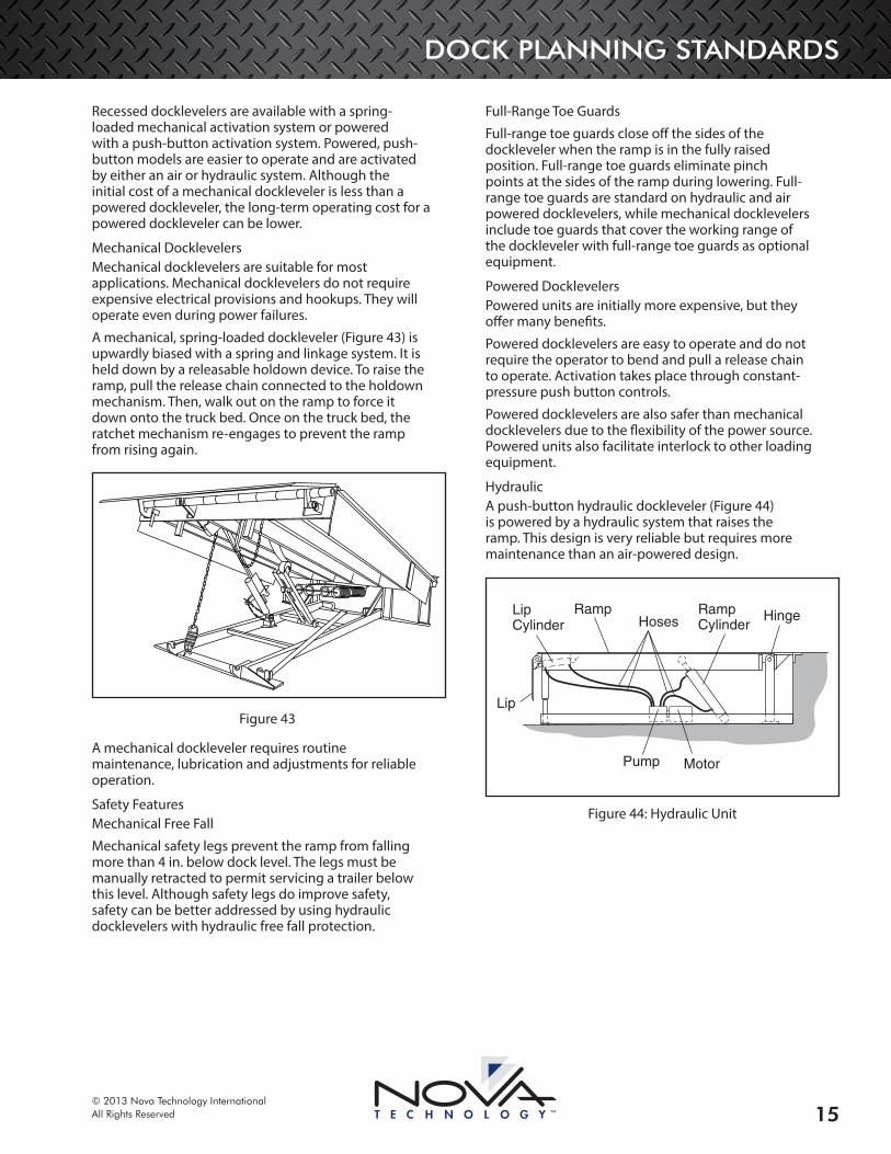
HydraulicA push-button hydraulic dockleveler (Figure 44) is powered by a hydraulic system that raises the ramp. This design is very reliable but requires more maintenance than an air-powered design.
HingeRampCylinder
RampHoses
LipCylinder
Lip
MotorPump
Figure 44: Hydraulic Unit
DOCK PLANNING STANDARDS
© 2013 Nova Technology InternationalAll Rights Reserved16
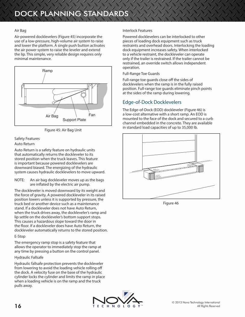
Air Bag
Air-powered docklevelers (Figure 45) incorporate the use of a low-pressure, high-volume air system to raise and lower the platform. A single push button activates the air power system to raise the leveler and extend the lip. This simple, very reliable design requires only minimal maintenance.
Fan
Ramp
Air BagSupport Plate
Figure 45: Air Bag Unit
Safety FeaturesAuto Return
Auto Return is a safety feature on hydraulic units that automatically returns the dockleveler to its stored position when the truck leaves. This feature is important because powered docklevelers are downward biased. The energizing of the hydraulic system causes hydraulic docklevelers to move upward.
OTE:N An air bag dockleveler moves up as the bags are inflated by the electric air pump.
The dockleveler is moved downward by its weight and the force of gravity. A powered dockleveler in its raised position lowers unless it is supported by pressure, the truck bed or another device such as a maintenance stand. If a dockleveler does not have Auto Return, when the truck drives away, the dockleveler’s ramp and lip settle on the dockleveler’s bottom support stops. This causes a hazardous slope toward the door in the floor. If a dockleveler does have Auto Return, the dockleveler automatically returns to the stored position.
E-Stop
The emergency ramp stop is a safety feature that allows the operator to immediately stop the ramp at any time by pressing a button on the control panel.
Hydraulic Fallsafe
Hydraulic fallsafe protection prevents the dockleveler from lowering to avoid the loading vehicle rolling off the dock. A velocity fuse on the base of the hydraulic cylinder locks the cylinder and limits the ramp in place when a loading vehicle is on the ramp and the truck pulls away.
Interlock Features
Powered docklevelers can be interlocked to other pieces of loading dock equipment such as truck restraints and overhead doors. Interlocking the loading dock equipment increases safety. When interlocked to a vehicle restraint, the dockleveler can operate only if the trailer is restrained. If the trailer cannot be restrained, an override switch allows independent operation.
Full-Range Toe Guards
Full-range toe guards close off the sides of docklevelers when the ramp is in the fully raised position. Full-range toe guards eliminate pinch points at the sides of the ramp during lowering.
Edge-of-Dock DocklevelersThe Edge-of-Dock (EOD) dockleveler (Figure 46) is a low-cost alternative with a short ramp. An EOD is mounted to the face of the dock and secured to a curb channel embedded in the concrete. They are available in standard load capacities of up to 35,000 lb.
Figure 46
DOCK PLANNING STANDARDS
© 2013 Nova Technology InternationalAll Rights Reserved 17
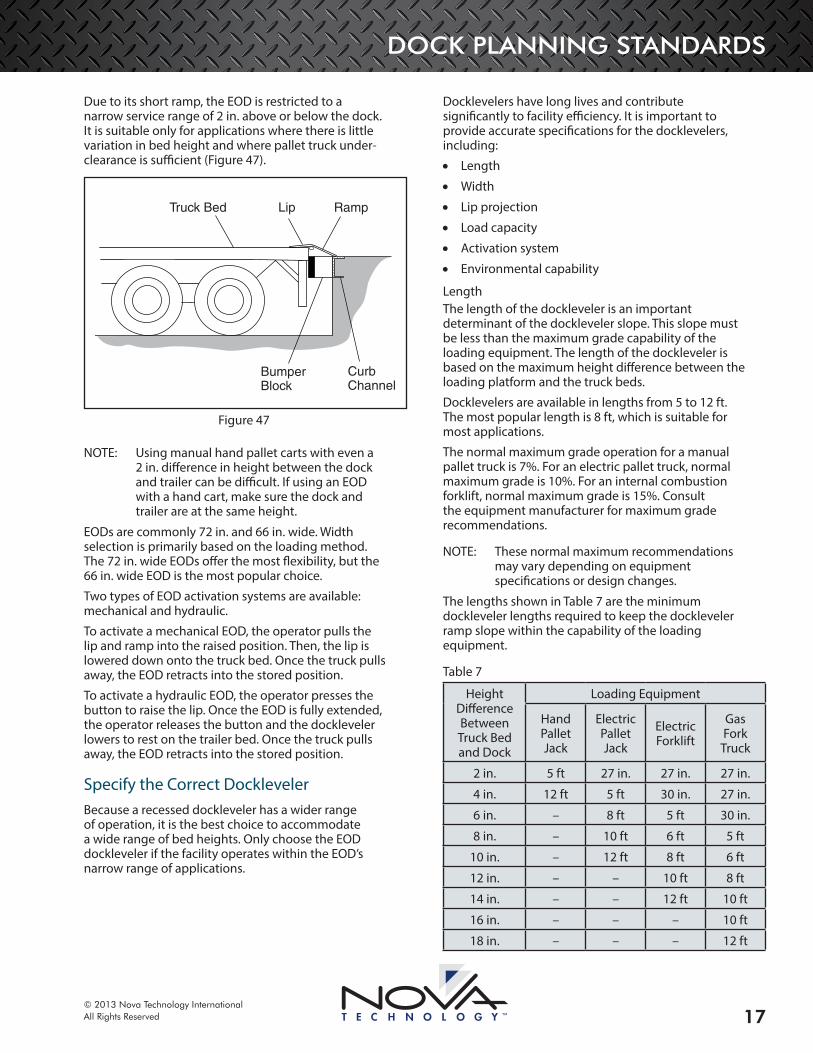
Due to its short ramp, the EOD is restricted to a narrow service range of 2 in. above or below the dock. It is suitable only for applications where there is little variation in bed height and where pallet truck under-clearance is sufficient (Figure 47).
Truck Bed Lip Ramp
BumperBlock
CurbChannel
Figure 47
OTE:N Using manual hand pallet carts with even a 2 in. difference in height between the dock and trailer can be difficult. If using an EOD with a hand cart, make sure the dock and trailer are at the same height.
EODs are commonly 72 in. and 66 in. wide. Width selection is primarily based on the loading method. The 72 in. wide EODs offer the most flexibility, but the 66 in. wide EOD is the most popular choice.
Two types of EOD activation systems are available: mechanical and hydraulic.
To activate a mechanical EOD, the operator pulls the lip and ramp into the raised position. Then, the lip is lowered down onto the truck bed. Once the truck pulls away, the EOD retracts into the stored position.
To activate a hydraulic EOD, the operator presses the button to raise the lip. Once the EOD is fully extended, the operator releases the button and the dockleveler lowers to rest on the trailer bed. Once the truck pulls away, the EOD retracts into the stored position.
Specify the Correct DocklevelerBecause a recessed dockleveler has a wider range of operation, it is the best choice to accommodate a wide range of bed heights. Only choose the EOD dockleveler if the facility operates within the EOD’s narrow range of applications.
Docklevelers have long lives and contribute significantly to facility efficiency. It is important to provide accurate specifications for the docklevelers, including:
• Length
• Width
• Lip projection
• Load capacity
• Activation system
• Environmental capability
LengthThe length of the dockleveler is an important determinant of the dockleveler slope. This slope must be less than the maximum grade capability of the loading equipment. The length of the dockleveler is based on the maximum height difference between the loading platform and the truck beds.
Docklevelers are available in lengths from 5 to 12 ft. The most popular length is 8 ft, which is suitable for most applications.
The normal maximum grade operation for a manual pallet truck is 7%. For an electric pallet truck, normal maximum grade is 10%. For an internal combustion forklift, normal maximum grade is 15%. Consult the equipment manufacturer for maximum grade recommendations.
OTE:N These normal maximum recommendations may vary depending on equipment specifications or design changes.
The lengths shown in Table 7 are the minimum dockleveler lengths required to keep the dockleveler ramp slope within the capability of the loading equipment.
Table 7
Height Difference Between Truck Bed and Dock
Loading Equipment
Hand Pallet Jack
Electric Pallet Jack
Electric Forklift
Gas Fork
Truck
2 in. 5 ft 27 in. 27 in. 27 in.
4 in. 12 ft 5 ft 30 in. 27 in.
6 in. – 8 ft 5 ft 30 in.
8 in. – 10 ft 6 ft 5 ft
10 in. – 12 ft 8 ft 6 ft
12 in. – – 10 ft 8 ft
14 in. – – 12 ft 10 ft
16 in. – – – 10 ft
18 in. – – – 12 ft
DOCK PLANNING STANDARDS
© 2013 Nova Technology InternationalAll Rights Reserved18
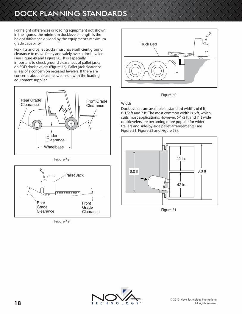
For height differences or loading equipment not shown in the figures, the minimum dockleveler length is the height difference divided by the equipment’s maximum grade capability.
Forklifts and pallet trucks must have sufficient ground clearance to move freely and safely over a dockleveler (see Figure 49 and Figure 50). It is especially important to check ground clearances of pallet jacks on EOD docklevelers (Figure 46). Pallet jack clearance is less of a concern on recessed levelers. If there are concerns about clearances, consult with the loading equipment supplier.
Rear GradeClearance
UnderClearance
Front GradeClearance
Wheelbase
Figure 48
RearGradeClearance
Pallet Jack
FrontGradeClearance
Figure 49
BumperBlock
CurbChannel
Truck Bed
Figure 50
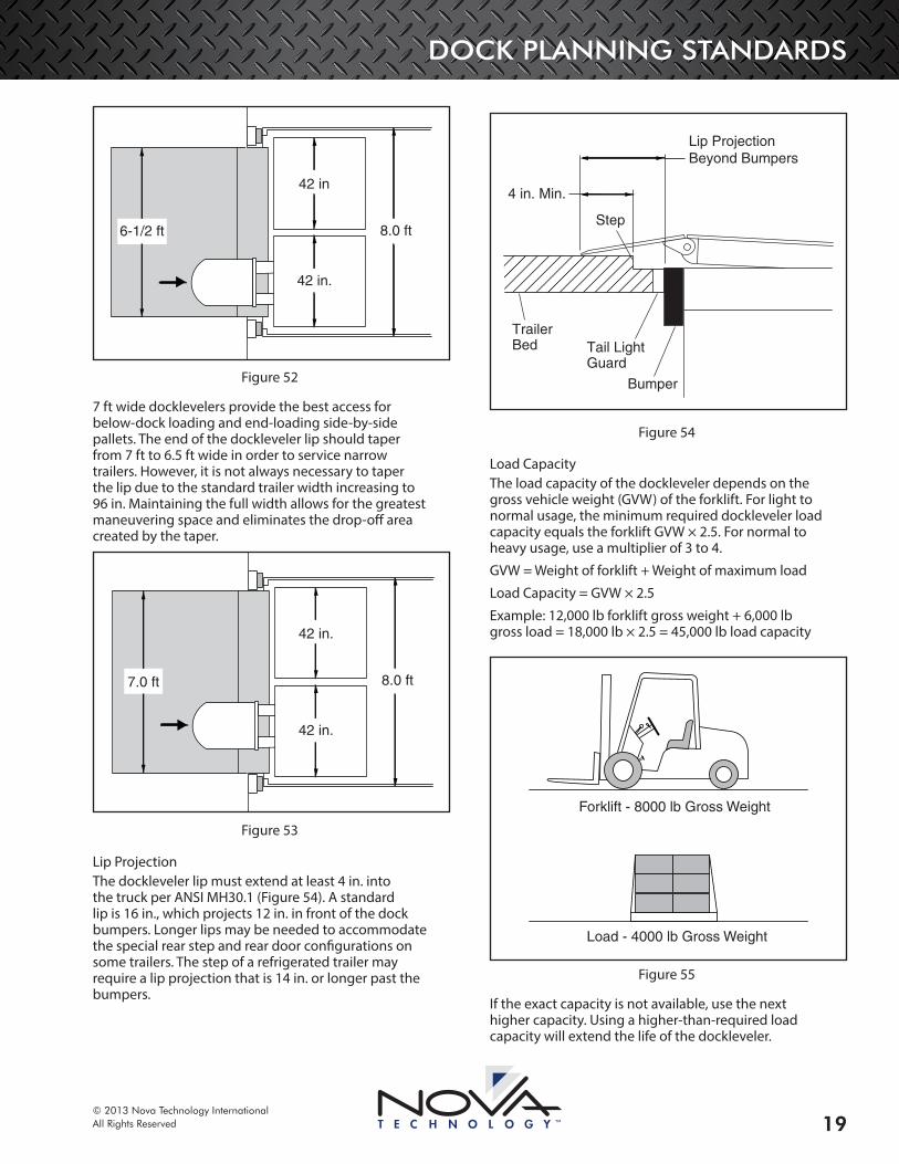
WidthDocklevelers are available in standard widths of 6 ft, 6-1/2 ft and 7 ft. The most common width is 6 ft, which suits most applications. However, 6-1/2 ft and 7 ft wide docklevelers are becoming more popular for wider trailers and side-by-side pallet arrangements (see Figure 51, Figure 52 and Figure 53).
42 in.
42 in.
8.0 ft 6.0 ft
Figure 51
DOCK PLANNING STANDARDS
© 2013 Nova Technology InternationalAll Rights Reserved 19
42 in.
42 in
8.0 ft6-1/2 ft
Figure 52
7 ft wide docklevelers provide the best access for below-dock loading and end-loading side-by-side pallets. The end of the dockleveler lip should taper from 7 ft to 6.5 ft wide in order to service narrow trailers. However, it is not always necessary to taper the lip due to the standard trailer width increasing to 96 in. Maintaining the full width allows for the greatest maneuvering space and eliminates the drop-off area created by the taper.
42 in.
42 in.
8.0 ft7.0 ft
Figure 53
Lip ProjectionThe dockleveler lip must extend at least 4 in. into the truck per ANSI MH30.1 (Figure 54). A standard lip is 16 in., which projects 12 in. in front of the dock bumpers. Longer lips may be needed to accommodate the special rear step and rear door configurations on some trailers. The step of a refrigerated trailer may require a lip projection that is 14 in. or longer past the bumpers.
4 in. Min.
Step
Lip ProjectionBeyond Bumpers
Trailer Bed Tail Light
Guard
Bumper
Figure 54
Load CapacityThe load capacity of the dockleveler depends on the gross vehicle weight (GVW) of the forklift. For light to normal usage, the minimum required dockleveler load capacity equals the forklift GVW × 2.5. For normal to heavy usage, use a multiplier of 3 to 4.
GVW = Weight of forklift + Weight of maximum load
Load Capacity = GVW × 2.5
Example: 12,000 lb forklift gross weight + 6,000 lb gross load = 18,000 lb × 2.5 = 45,000 lb load capacity
Forklift - 8000 lb Gross Weight
Load - 4000 lb Gross Weight
Figure 55
If the exact capacity is not available, use the next higher capacity. Using a higher-than-required load capacity will extend the life of the dockleveler.

DOCK PLANNING STANDARDS
© 2013 Nova Technology InternationalAll Rights Reserved20
The following conditions affect load capacity:
• Each dock position serves eight trucks or more each day
• Forklifts do not drive straight onto the dockleveler
• Forklifts with three wheels are used
• Forklift speeds exceed 4 mph
• Forklifts are equipped with front end attachments or fork side shifters
Activation SystemPush button activation is the most ergonomic and safest type of dockleveler activation system. Manual or spring counterbalance activation should be used only when electrical power is not available. Push button–operated docklevelers may be less expensive over the long term as they require less service.
Environmental CapabilityOn inside/outside docks at temperature-controlled facilities, use perimeter weather seals to help prevent outside air from entering the building.
At refrigerated facilities, the underside of the dockleveler ramp should be insulated. Condensation on the underside of the ramp causes corrosion and structural problems. Expanded foam insulation helps prevent the warmer outside air from condensing on the underside of the ramp. Insulation also saves energy by minimizing the loss of refrigerated air.
Optional FeaturesConsider adding optional features to increase the effectiveness of the installation.
Increase Lip LengthDock levelers are normally supplied with a 16 in. lip plate that will suit the majority of applications. Lip length can be increased to 18 in. to 20 in. projecting out further from the dock face. Increased lip projection is necessary to deal with bumper projections of more than 4 in., substantial dock and truck bed height differences, and setback internal truck beds – typical with refrigerated trucks and trailers.
Setback
Figure 56: Setback Internal Truck Bed
When loading or unloading a truck with a setback internal truck bed such as trailer with swing doors, the lip must be sized to ensure lip contact with the internal bed. If the lip does not project over the internal setback and therefore rests on the step below the internal truck bed, the material handling equipment will strike the edge of the step up to the bed on every entry, making product transfer both rough and inefficient.
Side/Rear WeathersealNeoprene strips attach along the sides and/or rear of the deck assembly to better control the climate. The preferred weatherseal to protect against rodent entry is brush seal.
GalvanizingThe zinc metalized spray process produces the optimal finish. Each dockleveler component is galvanized before assembly to provide complete protection. Galvanizing is commonly used in facilities that handle corrosive materials or are near harsh environments such as salt water.
Benefits of Hydraulic and Air Bag Docklevelers over Mechanical DocklevelersHydraulic docklevelers have lower lifetime ownership costs. Including maintenance, the estimated 10-year ownership costs for a dockleveler are $3200 for a mechanical dockleveler, and $1000 for a hydraulic or air bag dockleveler.
Air bag docklevelers are ergonomically correct, reducing the potential of employee injuries, and easier to use with their push button configuration.
Air bag docklevelers have a “stump-out” safety feature where fall safe legs impede below-dock and dock-level situations. The safety legs come to rest on the floor while the dockleveler is being used.
Hydraulic and air bag docklevelers log fewer hours and therefore have longer working lives. Because mechanical docklevelers are upward biased and the springs and holdown are in the stressed condition, the moving parts wear over time. However, hydraulic and air bag docklevelers are working only when they are being used and while the button is being pressed.
Hydraulic docklevelers increase safety on and around the loading dock. There is improved fall safe protection due to the velocity fuse fall safe over mechanical legs. The fuse will stop within 3 in. of drop.
Hydraulic docklevelers can accommodate higher load capacities. Mechanical and air bag docklevelers can handle a maximum rating of 55,000 lb, while hydraulic docklevelers can be used for load capacities of up to 100,000 lb.
DOCK PLANNING STANDARDS
© 2013 Nova Technology InternationalAll Rights Reserved 21
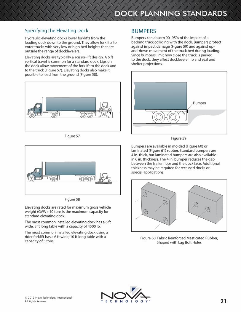
Specifying the Elevating DockHydraulic elevating docks lower forklifts from the loading dock down to the ground. They allow forklifts to enter trucks with very low or high bed heights that are outside the range of docklevelers.
Elevating docks are typically a scissor-lift design. A 6 ft vertical travel is common for a standard dock. Lips on the dock allow movement of the forklift to the dock and to the truck (Figure 57). Elevating docks also make it possible to load from the ground (Figure 58).
Figure 57
Figure 58
Elevating docks are rated for maximum gross vehicle weight (GVW); 10 tons is the maximum capacity for standard elevating dock.
The most common installed elevating dock has a 6 ft wide, 8 ft long table with a capacity of 4500 lb.
The most common installed elevating dock using a rider forklift has a 6 ft wide, 10 ft long table with a capacity of 5 tons.
BUMPERSBumpers can absorb 90–95% of the impact of a backing truck colliding with the dock. Bumpers protect against impact damage (Figure 59) and against up-and-down movement of the truck bed during loading. Since bumpers limit how close the truck is parked to the dock, they affect dockleveler lip and seal and shelter projections.
Bumper
Figure 59
Bumpers are available in molded (Figure 60) or laminated (Figure 61) rubber. Standard bumpers are 4 in. thick, but laminated bumpers are also available in 6 in. thickness. The 4 in. bumper reduces the gap between the trailer floor and the dock face. Additional thickness may be required for recessed docks or special applications.
Figure 60: Fabric Reinforced Masticated Rubber, Shaped with Lag Bolt Holes
DOCK PLANNING STANDARDS
© 2013 Nova Technology InternationalAll Rights Reserved22
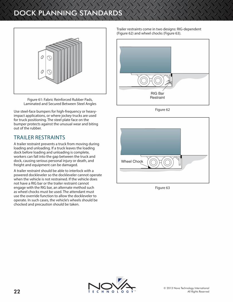
Figure 61: Fabric Reinforced Rubber Pads, Laminated and Secured Between Steel Angles
Use steel-face bumpers for high-frequency or heavy-impact applications, or where jockey trucks are used for truck positioning. The steel plate face on the bumper protects against the unusual wear and biting out of the rubber.
TRAILER RESTRAINTSA trailer restraint prevents a truck from moving during loading and unloading. If a truck leaves the loading dock before loading and unloading is complete, workers can fall into the gap between the truck and dock, causing serious personal injury or death, and freight and equipment can be damaged.
A trailer restraint should be able to interlock with a powered dockleveler so the dockleveler cannot operate when the vehicle is not restrained. If the vehicle does not have a RIG bar or the trailer restraint cannot engage with the RIG bar, an alternate method such as wheel chocks must be used. The attendant must use the override function to allow the dockleveler to operate. In such cases, the vehicle’s wheels should be chocked and precaution should be taken.
Trailer restraints come in two designs: RIG-dependent (Figure 62) and wheel chocks (Figure 63).
RIG BarRestraint
Figure 62
Wheel Chock
Figure 63
DOCK PLANNING STANDARDS
© 2013 Nova Technology InternationalAll Rights Reserved 23
RIG-Dependent RestraintsThe most common type of trailer restraint is the RIG-dependent system. Most over-the-road trailers have rear impact guards, or RIG bars. RIG-dependent restraint systems use a restraint barrier that rises up, captures the trailer’s RIG bar, and uses it to lock the trailer in place (Figure 63 and Figure 64).
A powered-activated restraint can use programmable controls that offer flexibility between the restraint and other loading dock equipment.
A RIG restraint engagement sensor is standard on a powered-activated restraint system and optional on a manual restraint system.
A manual wheel chock is a tapered block that is wedged in front of the wheels to prevent accidental movement.
RIG-dependent restraints are available in manual and powered activation designs. These restraints can engage underride guards from 7-1/2 to 30 in. off grade.
A manual restraint uses a push bar to raise and lower the release latch on the restraint.
RIG BarRestraint
Figure 64
RIG BarRestraint
Figure 65
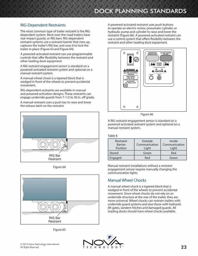
A powered-activated restraint uses push buttons to operate an electric motor, pneumatic cylinder, or hydraulic pump and cylinder to raise and lower the restraint (Figure 66). A powered-activated restraint can use a control system that offers flexibility between the restraint and other loading dock equipment.
CAUTION !!
RELEASE
TRUCKLOCK
WARNING !!BEFORE ENTERING
TRAILER OVER-RIDERESET
AUDIBLEALARM
OUTSIDE LIGHT INDICATOR
WHEN GREENLIGHT IS ON,
VERIFY THAT TRAILERIS SECURED
BY TRUCK LOCK
RESTRAIN
TRUCKLOCK
ENTER ONGREEN ONLY
DO NOT ENTERON RED
Figure 66
A RIG restraint engagement sensor is standard on a powered-activated restraint system and optional on a manual restraint system.
Table 8
Restraint Barrier
Position
Outside Communication
Light
Inside Communication
LightStored Green RedEngaged Red Green
Manual restraint installations without a restraint engagement sensor require manually changing the communication lights.
Manual Wheel ChocksA manual wheel chock is a tapered block that is wedged in front of the wheels to prevent accidental movement. Since wheel chocks do not rely on an underride structure at the rear of the trailer, they are more universal. Wheel chocks can restrain trailers with underride guard systems and also those with hydraulic lift gates, tandem hitches and damaged guards. All loading docks should have wheel chocks available.

DOCK PLANNING STANDARDS
© 2013 Nova Technology InternationalAll Rights Reserved24
Manual wheel chocks have disadvantages:
• Dock workers may find wheel chocks inconvenient and not use them.
• The trailer cannot be secured if the wheel chocks are lost or stolen.
• Manually positioning the wheel chocks can be time-consuming.
• A truck can pull a trailer over the wheel chocks, whereas a typical RIG vehicle restraint will withstand a force of more than 30,000 lb and is more effective at preventing unintended trailer departures.
COMMUNICATION LIGHTSCommunication lights greatly contribute to the overall safety of the loading dock.
A two-way communication system consists of the following components:
• Outside signal light
• One regular and one reversible instruction sign (Figure 67)
• Interior control panel
• Sign indicating to the operator to load or unload on the green light only
STOPONRED
STOPONRED
Figure 67: Outside Signal Lights and Signs
DOCK RUN-OFF PROTECTIONProvide run-off protection on unoccupied dock positions so that loading equipment will not accidentally drive off the edge of the dock, which can cause serious injury or death, and damage the forklift, freight, and building. Types of dock run-off protection include gate barriers and lip barriers.
OTE:N Barriers are not effective at stopping loading equipment traveling faster than 4 mph.
Gate BarriersGate barriers are safety gates that are placed in front of the dock door to protect the dock door and door tracks from collisions with forklifts, and to prevent pedestrians from walking off the dock. The gates should extend the full width of the door. When the gates are open, the full width of the door is available for pass-through. Gates increase the life of the door by preventing door damage.
Figure 68
Lip BarriersLip barriers provide run-off protection through a barrier that extends 5 in. above floor level when the leveler lip is stored (Figure 69).
Run-offProtector
Figure 69
DOCK PLANNING STANDARDS
© 2013 Nova Technology InternationalAll Rights Reserved 25
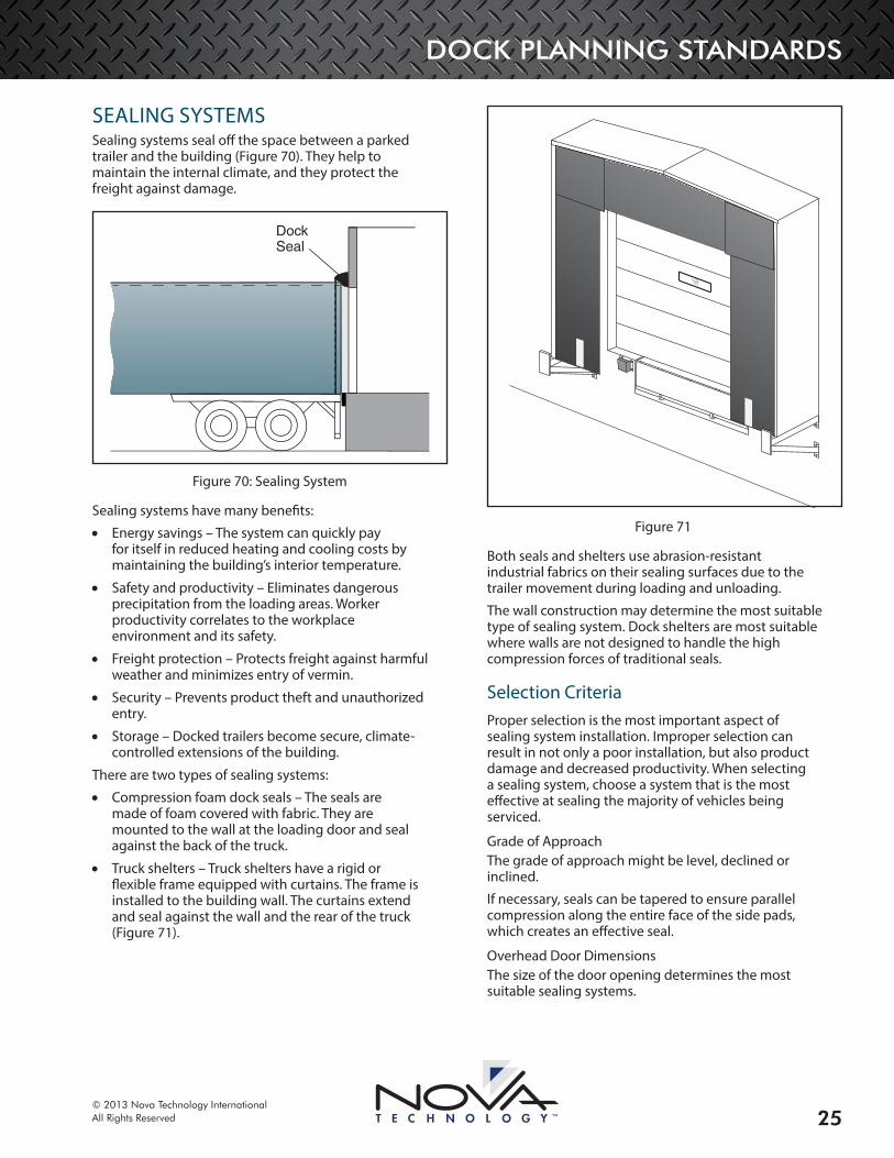
SEALING SYSTEMSSealing systems seal off the space between a parked trailer and the building (Figure 70). They help to maintain the internal climate, and they protect the freight against damage.
DockSeal
Figure 70: Sealing System
Sealing systems have many benefits:
• Energy savings – The system can quickly pay for itself in reduced heating and cooling costs by maintaining the building’s interior temperature.
• Safety and productivity – Eliminates dangerous precipitation from the loading areas. Worker productivity correlates to the workplace environment and its safety.
• Freight protection – Protects freight against harmful weather and minimizes entry of vermin.
• Security – Prevents product theft and unauthorized entry.
• Storage – Docked trailers become secure, climate-controlled extensions of the building.
There are two types of sealing systems:
• Compression foam dock seals – The seals are made of foam covered with fabric. They are mounted to the wall at the loading door and seal against the back of the truck.
• Truck shelters – Truck shelters have a rigid or flexible frame equipped with curtains. The frame is installed to the building wall. The curtains extend and seal against the wall and the rear of the truck (Figure 71).
Figure 71
Both seals and shelters use abrasion-resistant industrial fabrics on their sealing surfaces due to the trailer movement during loading and unloading.
The wall construction may determine the most suitable type of sealing system. Dock shelters are most suitable where walls are not designed to handle the high compression forces of traditional seals.
Selection Criteria Proper selection is the most important aspect of sealing system installation. Improper selection can result in not only a poor installation, but also product damage and decreased productivity. When selecting a sealing system, choose a system that is the most effective at sealing the majority of vehicles being serviced.
Grade of ApproachThe grade of approach might be level, declined or inclined.
If necessary, seals can be tapered to ensure parallel compression along the entire face of the side pads, which creates an effective seal.
Overhead Door DimensionsThe size of the door opening determines the most suitable sealing systems.
DOCK PLANNING STANDARDS
© 2013 Nova Technology InternationalAll Rights Reserved26
Dock Bumper ProjectionThe dock bumper projection is the distance between the wall and the front face of the bumper. On declined driveways, the bumper must project far enough to prevent trucks from impacting the upper wall.
Dock HeightThe dock height is the distance between the grade and the top of the dock floor.
Mounting SurfaceThe wall construction may determine the most suitable type of sealing system. Dock shelters are most suitable where walls are not designed to handle the high compression forces of traditional seals.
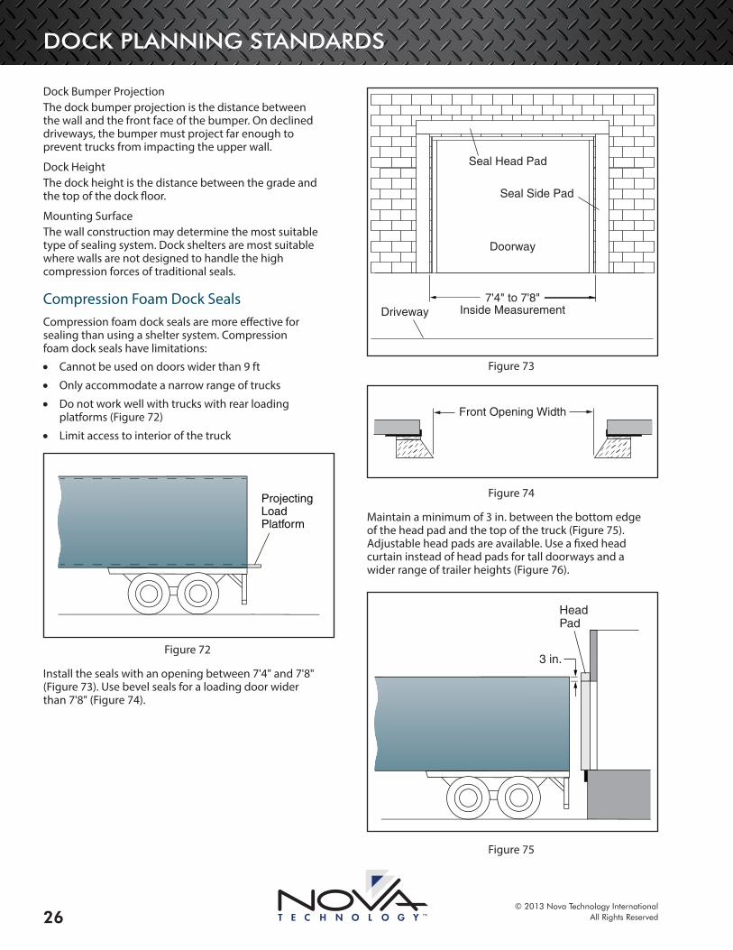
Compression Foam Dock SealsCompression foam dock seals are more effective for sealing than using a shelter system. Compression foam dock seals have limitations:
• Cannot be used on doors wider than 9 ft
• Only accommodate a narrow range of trucks
• Do not work well with trucks with rear loading platforms (Figure 72)
• Limit access to interior of the truck
Projecting LoadPlatform
Figure 72
Install the seals with an opening between 7'4" and 7'8" (Figure 73). Use bevel seals for a loading door wider than 7'8" (Figure 74).
Seal Side Pad
7'4" to 7'8"Inside Measurement
Doorway
Driveway
Seal Head Pad
Figure 73
Front Opening Width
Figure 74
Maintain a minimum of 3 in. between the bottom edge of the head pad and the top of the truck (Figure 75). Adjustable head pads are available. Use a fixed head curtain instead of head pads for tall doorways and a wider range of trailer heights (Figure 76).
HeadPad
3 in.
Figure 75
DOCK PLANNING STANDARDS
© 2013 Nova Technology InternationalAll Rights Reserved 27
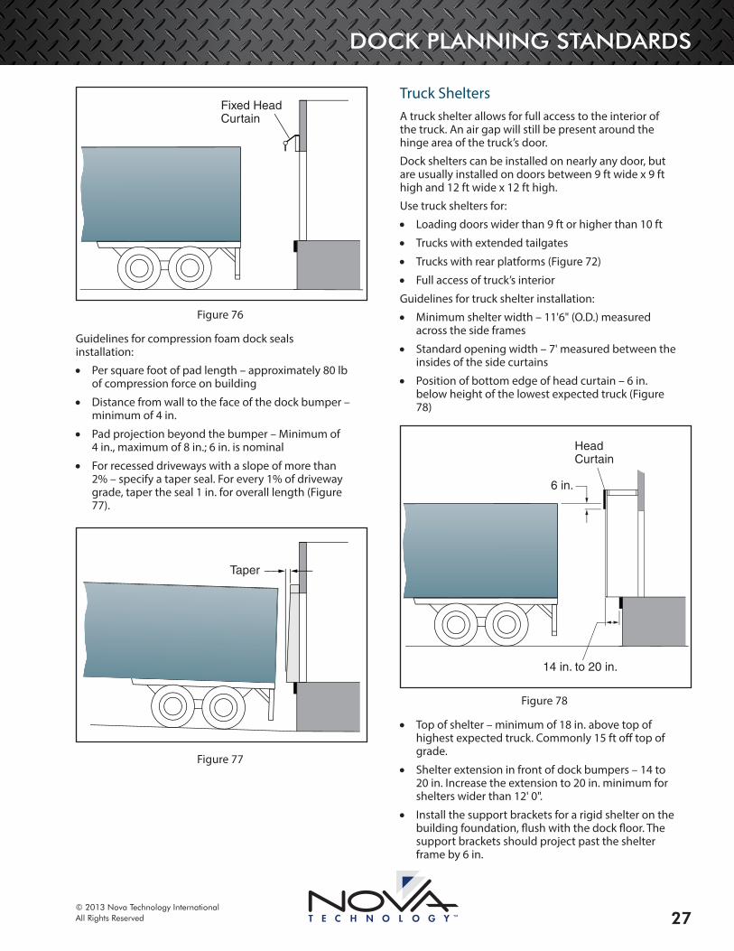
Fixed HeadCurtain
Figure 76
Guidelines for compression foam dock seals installation:
• Per square foot of pad length – approximately 80 lb of compression force on building
• Distance from wall to the face of the dock bumper – minimum of 4 in.
• Pad projection beyond the bumper – Minimum of 4 in., maximum of 8 in.; 6 in. is nominal
• For recessed driveways with a slope of more than 2% – specify a taper seal. For every 1% of driveway grade, taper the seal 1 in. for overall length (Figure 77).
Taper
Figure 77
Truck SheltersA truck shelter allows for full access to the interior of the truck. An air gap will still be present around the hinge area of the truck’s door.
Dock shelters can be installed on nearly any door, but are usually installed on doors between 9 ft wide x 9 ft high and 12 ft wide x 12 ft high.
Use truck shelters for:
• Loading doors wider than 9 ft or higher than 10 ft
• Trucks with extended tailgates
• Trucks with rear platforms (Figure 72)
• Full access of truck’s interior
Guidelines for truck shelter installation:
• Minimum shelter width – 11'6" (O.D.) measured across the side frames
• Standard opening width – 7' measured between the insides of the side curtains
• Position of bottom edge of head curtain – 6 in. below height of the lowest expected truck (Figure 78)
HeadCurtain
6 in.
14 in. to 20 in.
Figure 78
• Top of shelter – minimum of 18 in. above top of highest expected truck. Commonly 15 ft off top of grade.
• Shelter extension in front of dock bumpers – 14 to 20 in. Increase the extension to 20 in. minimum for shelters wider than 12' 0".
• Install the support brackets for a rigid shelter on the building foundation, flush with the dock floor. The support brackets should project past the shelter frame by 6 in.
DOCK PLANNING STANDARDS
© 2013 Nova Technology InternationalAll Rights Reserved28
Dock LightsBecause trailers do not usually have interior lights, they are dark and hazardous. Provide loading lights at each dock position to improve visibility and reduce injury hazards.
CONTACT NOVAThe information in this manual addresses standards for dock planning. If you have a unique situation not addressed in this manual, please contact NOVA Technology at 800-236-7325 or visit their website at www.novalocks.com.

DOCK PLANNING STANDARDS
© 2013 Nova Technology InternationalAll Rights ReservedB Printed in U.S.A.
N90W14507 Commerce Drive, Menomonee Falls, WI 53051
phone 262-502-1591 | 800-236-7325 | fax 262-502-1511
www.novalocks.com


