44
Manual NIBE TM MT-WH 2029-F/1FS and NIBE TM MT-WH 2029-1FS DOMESTIC HOT WATER HEAT PUMP OE01:935-1706 EN
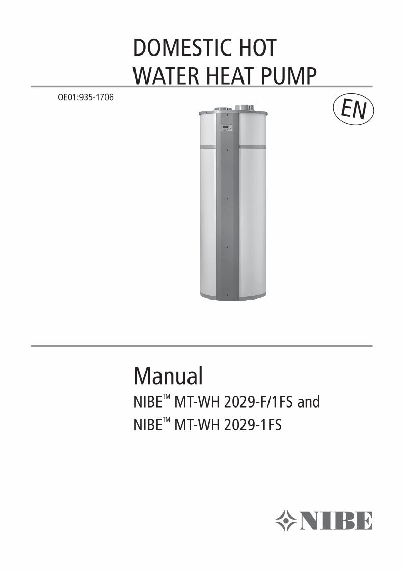
Manual NIBETM MT-WH 2029-F/1FS and NIBETM MT-WH 2029-1FS
DOMESTIC HOT WATER HEAT PUMP
OE01:935-1706 EN
OE0
1-93
5-14
08 M
anua
l arti
cle n
o. 7
1425
5999
2
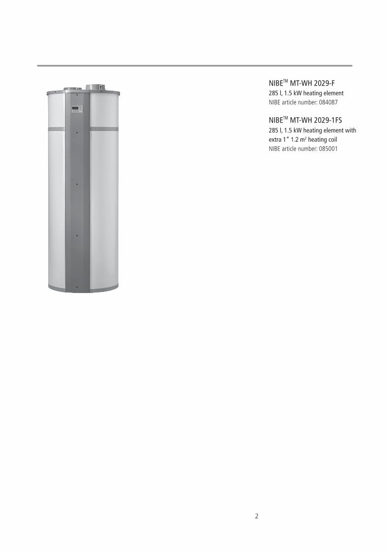
NIBETM MT-WH 2029-F285 l, 1.5 kW heating element NIBE article number: 084087
NIBETM MT-WH 2029-1FS285 l, 1.5 kW heating element with extra 1” 1.2 m2 heating coilNIBE article number: 085001
3
Table of Contents
1 Transport 6
1.1 Delivery mode 6
1.2 Storage 6
1.3 Transport with forklift 6
1.4 Unloading the heat pump 6
1.5 Transport with trolley 6
1.6 Tilting of unit 6
2 Dimensions 7
3 About the product 8
3.1 General 8
3.2 Scope of delivery 8
3.3 Product description 8
3.4 Operation of the NIBE MT-WH 2029-F/1FS 8
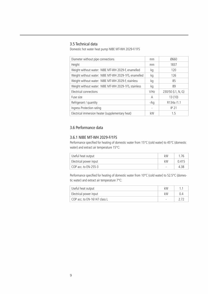
3.5 Technical data 9
3.6 Performance data 9
3.6.1 NIBE MT-WH 2029-F/1FS 9
3.7 Operating range / limits 10
3.8 Sound level 10
3.9 Domestic hot water tank 10
3.10 Airflow 10
3.11 Refrigerant circuit – description 11
3.11.1 Refrigerant circuit – diagram 11
3.12 Requirements for the water circuit 11
3.12.1 Water circuit - diagram 12
3.13 Electrical diagram Optima 170 Control 13
3.14 Fan Capacity 14
4
4 Before Installation and start up 15
4.1 Important safety instructions 15
4.1.1 Cooling system – safety instructions 15
4.1.2 Electrical circuit – safety instructions 15
4.1.3 Water circuit – safety instructions 15
4.1.4 Users 15
5 Installation 16
5.1 Location 16
5.2 Set-up sequence 16
5.3 Water connections 18
5.4 Location of connecting pipes 18
5.5 Connection of condensate drain 18
5.6 Air intake, air exhaust and connections 19
5.7 Connection of NIBE MT-WH 2029-1FS heating coil 19
6 Commissioning 20
6.1 Leak test 20
6.2 Commissioning of the water circuit 20
6.3 Commissioning of the air circuit 20
6.4 Commissioning of the electrical circuit 20
7 Controls and Operations 21
7.1 Control panel Optima 170 21
7.2 Operation 21
7.3 Main Menu 21
7.3.1 Display view (main menu) 23
7.4 Service menu 23
7.4.1 Changing settings in the service menu 23
7.4.2 Service menu points 23
7.5 Table for set points 32
7.6 Table for defrosting 33
Table of Contents
5
7.7 Functional description 33
7.7.1 Controlling Domestic hot water heat pump with Optima 170 34
7.7.2 Performance 34
7.7.3 The function of the heat pump 34
7.7.4 Water heating 34
7.7.5 Fan operation 34
7.7.6 Defrosting 34
7.7.7 Extra heating capacity 35
7.7.8 Photovoltaic function 35
7.7.9 Timer function 37
7.8 Safety features 37
7.8.1 High pressure switch 37
7.8.2 Safety breakers 37
7.9 Alarms 37
7.9.1 PE: High pressure switch alarm 37
7.9.2 Er6: Atypical evaporator temperatures 37
8 Maintenance 38
8.1 Environmental requirements 38
8.2 Cooling system and fan 38
8.3 Condensation and condensate drain 38
8.4 Water circulation and water tank 38
8.4.1 Pressure relief valve 38
8.4.2 Anode 39
9 Disassembly/decommissioning 40
10 Troubleshooting 40
10.1 The heat pump does not supply hot water 40
11 Warranty provisions 41
12 Declaration of conformity 42
13 Product and installer information 43
6
1 Transport
Immediately upon receipt, examine the domestic hot water heater pump to make sure that it is intact and undamaged. If not, inform this to the shipping company immediately. All shipments are the responsibility of the recipient unless otherwise agreed.
1.1 Delivery modeNIBE MT-WH 2029-F/1FS is delivered without condensate drain tube and the safety equipment for the water circuit.
1.2 StorageNIBE MT-WH 2029-F/1FS must be stored and transported upright free of water and within its packaging.
Transport and storage may take place at temperatures between -10 °C and +50 °C. If the unit has been transported or stored at sub-zero temperatures leave the unit at room temperatures for 24 hrs before commissioning.
1.3 Transport with forklift For transport with a forklift, the NIBE MT-WH 2029-F/1FS must stand on the associated transport frame. Always lift the unit slowly. Due to the high centre of gravity, the NIBE MT-WH 2029-F/1FS must be secured against tipping during transportation.
1.4 Unloading the heat pump In order to avoid damages, the NIBE MT-WH 2029-F/1FS must be unloaded on a flat surface.
1.5 Transport with trolleyThe NIBE MT-WH 2029-F/1FS must only be transported on the associated transport frame. This also applies to transport on stairs. The transport frame measures approx. 70x76 cm incl. packag-ing. The NIBE MT-WH 2029-F/1FS must be secured against sliding on the trolley. Water connections etc. may not be used for transportation purposes. Make sure that the trolley does not damage the cabinet or the various connections.
1.6 Tilting of unitWhen carefully and manually transporting the NIBE MT-WH 2029-F/1FS over a short distance to its final location the unit can be tilted up to 45°. If this limit is exceeded, the NIBE MT-WH 2029-F/1FS must be left in its normal upright position for at least 1 hour before it is started.
The unit must not be transported horizontally by an automotive vehicle (e.g. lorry, van or trailer). There is a great risk that the compressor fixation will be damaged beyond repair. Observe the tilt watch indicators.
7
2 Dimensions
1 Extract air Ø 160 mm
2 Exhaust air Ø 160 mm
3 Circuit board
4 Condensate drain Ø 19 mm
5 Compressor
6 Solenoid valve
7 Check valve
8 285 litre water tank
9 Service flange
10 1,5 kW 230V electric cartridge
11 Anode
12 Cold water connection 3/4”
Enamelled: BSPT (ISO 7-1)
Stainless: Ø22
13 Hot water circulation 3/4”
Enamelled: BSPT (ISO 7-1)
Stainless: Ø22
14 Hot water connection 3/4”
Enamelled: BSPT (ISO 7-1)
Stainless: Ø22
15 Heating coil in 3/4” (Only 1FS)
Enamelled: BSPT (ISO 7-1)
Stainless: Ø22
16 Heating coil out 3/4” (Only 1FS)
Enamelled: BSPT (ISO 7-1)
Stainless: Ø22
17 High pressure switch
18 Thermostatic expansion valve
19 Fan
General arrangement NIBE MT-WH 2029-F/1FSAll dimensions in mm.
Value NIBE MT-WH 2029-F/1FS
D Ø660
H 1835
H1 110
H2 (only 1FS) 250
H3 (only 1FS) 615
H4 900
H5 1410
8
3 About the product
3.1 GeneralThe domestic hot water heat pump has been designed and produced according to all relevant EU guidelines (please also refer to the EEC-declaration of conformity).
3.2 Scope of delivery• Domestic hot water heat pump with built-in control.• Manual including installation guidelines, operating instructions and technical data.
3.3 Product descriptionThe NIBE MT-WH 2029-F/1FS is a domestic hot water heat pump, ready made for installation.It consists of cabinet, components for refrigerant, air and water circuits as well as control panel, and control and monitoring equipment designed for automatic operation.The NIBE MT-WH 2029-F/1FS uses the heat from the extract air to produce hot water. At peak times extra heat can be supplied through an integrated electrical immersion heater of 1.5 kW.There is a sensor pocket in the water tank in which an external thermostat or sensor (diameter 6 mm) from an external control can be mounted.
The application area and operating principles of the heat pump are specified in this manual.
3.4 Operation of the NIBE MT-WH 2029-F/1FSThe control starts the compressor when hot water is needed. The compressor operates until the water in the water tank reaches the set temperature. Usually, the NIBE MT-WH 2029-F/1FS can produce enough hot water to cover the need of a household of 4 persons.
If the NIBE MT-WH 2029-F/1FS is not able to produce enough domestic hot water, an electrical immersion heater integrated in the water tank can be activated. This way more domestic hot water can be produced. It is possible to set the temperature to which the electrical immersion heater should heat the water. The electrical immersion heater should only be used when there is a need, as it consumes significantly more energy that the compressor.
Any work carried out on this unit must only be done by skilled personnel.Take all necessary precautions to avoid accidents.
9
Diameter without pipe connections mm Ø660
Height mm 1837
Weight without water: NIBE MT-WH 2029-F, enamelled kg 120
Weight without water: NIBE MT-WH 2029-1FS, enamelled kg 126
Weight without water: NIBE MT-WH 2029-F, stainless kg 85
Weight without water: NIBE MT-WH 2029-1FS, stainless kg 89
Electrical connections V/Hz 230/50 (L1, N, G)
Fuse size A 13 (10)
Refrigerant / quantity -/kg R134a /1.1
Ingress Protection rating - IP 21
Electrical immersion heater (supplementary heat) kW 1.5
Useful heat output kW 1.76
Electrical power input kW 0.415
COP acc. to EN-255-3 - 4.38
Useful heat output kW 1.1
Electrical power input kW 0.4
COP acc. to EN-16147 class L - 2.72
3.6 Performance data
3.6.1 NIBE MT-WH 2029-F/1FSPerformance specified for heating of domestic water from 15°C (cold water) to 45°C (domestic water) and extract air temperature 15°C:
Performance specified for heating of domestic water from 10°C (cold water) to 52.5°C (domes-tic water) and extract air temperature 7°C:
3.5 Technical dataDomestic hot water heat pump NIBE MT-WH 2029-F/1FS
10
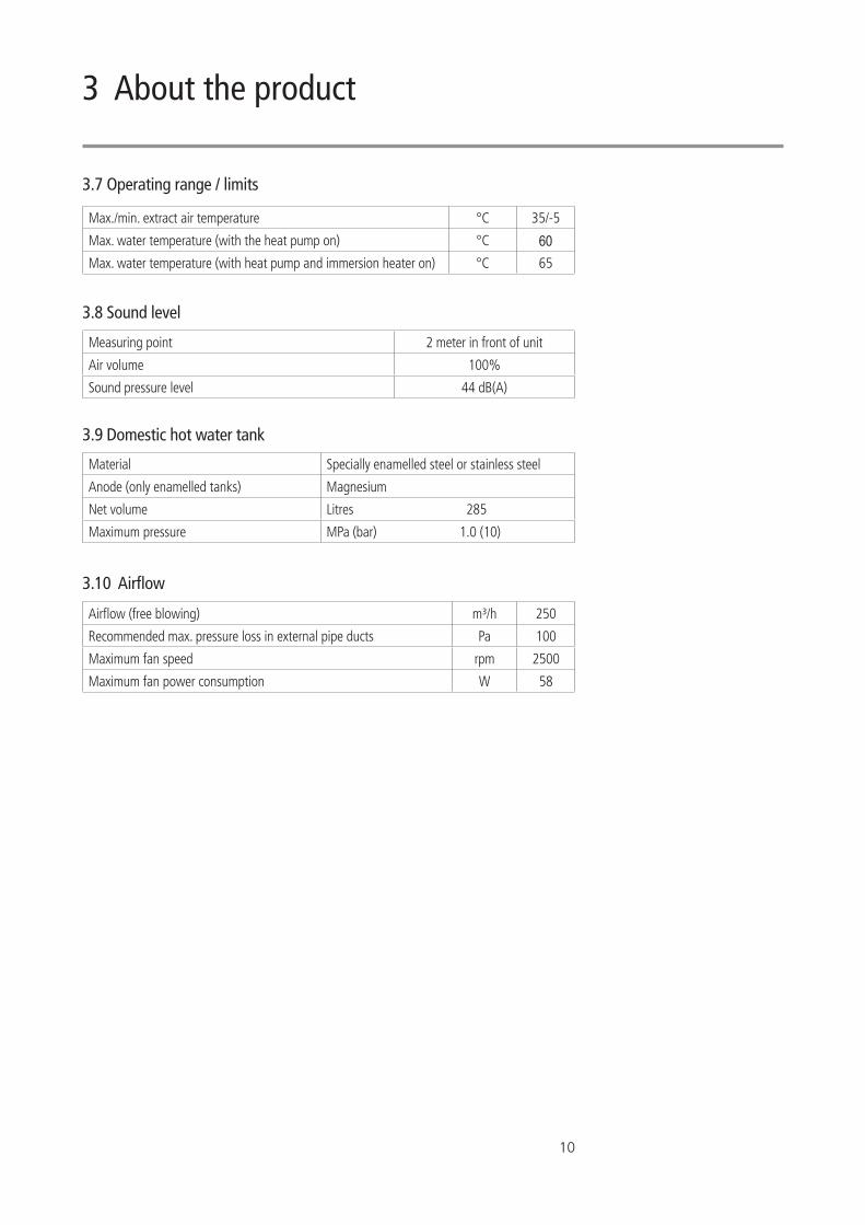
3.7 Operating range / limits
3.8 Sound level
3.9 Domestic hot water tank
3.10 Airflow
Max./min. extract air temperature °C 35/-5
Max. water temperature (with the heat pump on) °C 60Max. water temperature (with heat pump and immersion heater on) °C 65
Measuring point 2 meter in front of unit
Air volume 100%
Sound pressure level 44 dB(A)
Material Specially enamelled steel or stainless steel
Anode (only enamelled tanks) Magnesium
Net volume Litres 285
Maximum pressure MPa (bar) 1.0 (10)
Airflow (free blowing) m³/h 250
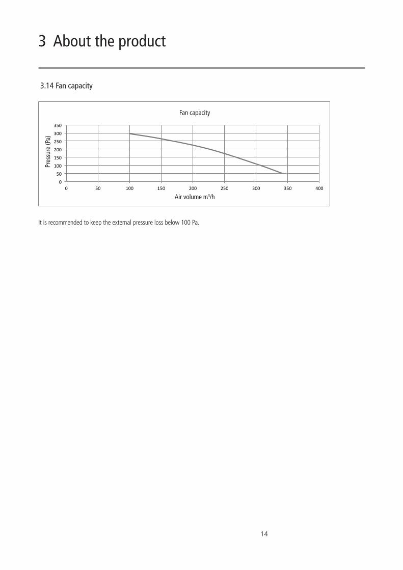
Recommended max. pressure loss in external pipe ducts Pa 100
Maximum fan speed rpm 2500
Maximum fan power consumption W 58
3 About the product
11
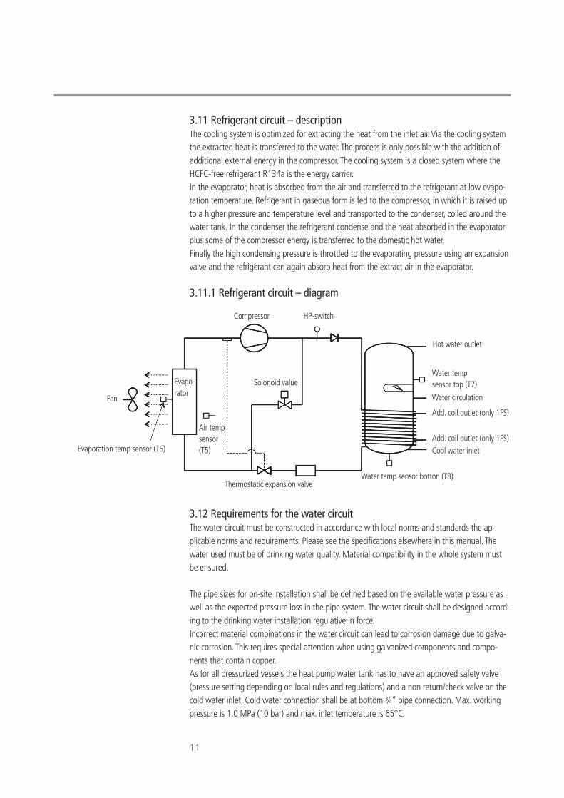
3.11 Refrigerant circuit – descriptionThe cooling system is optimized for extracting the heat from the inlet air. Via the cooling system the extracted heat is transferred to the water. The process is only possible with the addition of additional external energy in the compressor. The cooling system is a closed system where the HCFC-free refrigerant R134a is the energy carrier.In the evaporator, heat is absorbed from the air and transferred to the refrigerant at low evapo-ration temperature. Refrigerant in gaseous form is fed to the compressor, in which it is raised up to a higher pressure and temperature level and transported to the condenser, coiled around the water tank. In the condenser the refrigerant condense and the heat absorbed in the evaporator plus some of the compressor energy is transferred to the domestic hot water.Finally the high condensing pressure is throttled to the evaporating pressure using an expansion valve and the refrigerant can again absorb heat from the extract air in the evaporator.
3.11.1 Refrigerant circuit – diagram
3.12 Requirements for the water circuitThe water circuit must be constructed in accordance with local norms and standards the ap-plicable norms and requirements. Please see the specifications elsewhere in this manual. The water used must be of drinking water quality. Material compatibility in the whole system must be ensured.
The pipe sizes for on-site installation shall be defined based on the available water pressure as well as the expected pressure loss in the pipe system. The water circuit shall be designed accord-ing to the drinking water installation regulative in force.Incorrect material combinations in the water circuit can lead to corrosion damage due to galva-nic corrosion. This requires special attention when using galvanized components and compo-nents that contain copper.As for all pressurized vessels the heat pump water tank has to have an approved safety valve (pressure setting depending on local rules and regulations) and a non return/check valve on the cold water inlet. Cold water connection shall be at bottom ¾” pipe connection. Max. working pressure is 1.0 MPa (10 bar) and max. inlet temperature is 65°C.
Compressor HP-switch
Solonoid value
Hot water outlet
Water tempsensor top (T7)
Water circulation
Add. coil outlet (only 1FS)
Add. coil outlet (only 1FS)Cool water inlet
Water temp sensor botton (T8)Thermostatic expansion valve
Air temp sensor (T5)Evaporation temp sensor (T6)
Fan
Evapo-rator
12
Dirt must be avoided in the pipe system (if necessary flush the pipes before the heat pump is connected)!When no circulation pipe is connected to the heat pump, the circulation connection must be sealed accordingly!
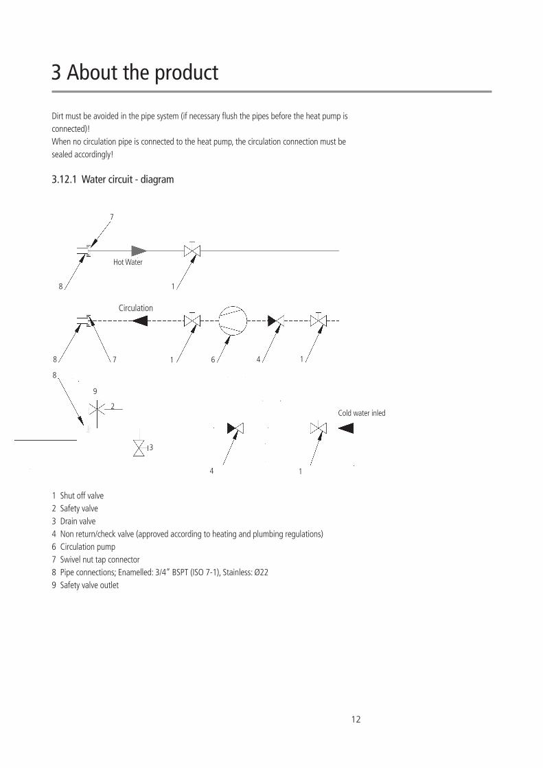
3.12.1 Water circuit - diagram
1 Shut off valve2 Safety valve 3 Drain valve4 Non return/check valve (approved according to heating and plumbing regulations)6 Circulation pump7 Swivel nut tap connector8 Pipe connections; Enamelled: 3/4” BSPT (ISO 7-1), Stainless: Ø229 Safety valve outlet
3 About the product
8
8
8
7
7 1 6 4 1
14
3
1
2
9
Hot Water
Circulation
Cold water inled
13
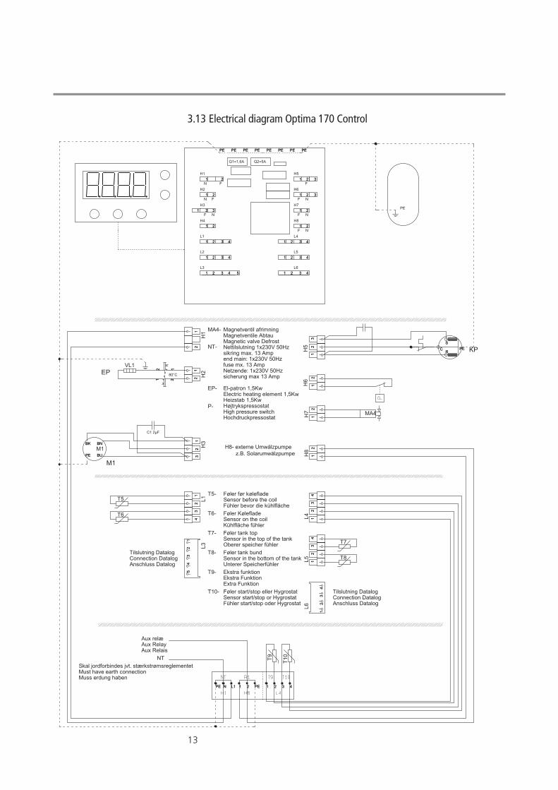
EP
M1
KP
NT
Aux relæAux RelayAux Relais
El-patron 1,5KwElectric heating element 1,5KwHeizstab 1,5KwHøjtrykspressostatHigh pressure switchHochdruckpressostat
Magnetventil afrimningMagnetventile AbtauMagnetic valve DefrostNettilslutning 1x230V 50Hz sikring max. 13 Ampend main: 1x230V 50Hz fuse mx. 13 AmpNetzende: 1x230V 50Hz sicherung max 13 Amp
Skal jordforbindes jvt. stærkstrømsreglementetMust have earth connectionMuss erdung haben
Tilslutning DatalogConnection DatalogAnschluss Datalog
Tilslutning DatalogConnection DatalogAnschluss Datalog
MA4-
NT-
EP-
P-
T5-
T6-
T7-
T8-
T9-
T10-
80°C
Føler før kølefladeSensor before the coilFühler bevor die kühlfläche
Føler KølefladeSensor on the coilKühlfläche fühler
Føler tank topSensor in the top of the tankOberer speicher fühler
Føler tank bundSensor in the bottom of the tankUnterer Speicherfühler
Ekstra funktionEkstra FunktionExtra Funktion
Føler start/stop eller HygrostatSensor start/stop or HygrostatFühler start/stop oder Hygrostat
12
12
H1
12
12 H
2
12
12
H5
12
12
H7
12
12
H8
12
34
12
34
L1
12
34
12
34
L41
23
41
23
4
L5
12
31
23
H3
12
31
23
H6
12
34
51
23
45
L3
12
34
12
34
L6
11 22 3 4L1N PEPE 11 22 3 4L1N PEPE
T5
T6
T7
T8
VL1
MA4
C1 2µF
BU
BNBK
PE BU
BNBK
PE
M1
C PER
S
C PER
S
T9
T10
PE
12 121 21 2
1
1
1
1
1
1 1
1
1
1
1
1
11
2 2
2
2
2
2
2
2
2
2
2
2
2 2
3
3
3
3
3
3
3
3
3
4
4
4
4
4
4
5
EPEPPE PEPE PEPE PE
Q1=1,6A Q2=5A
H1
H2
H3
H4
H5
H6
H7
H8
L1
L2
L4
L5
L3 L6
F
F
F
F
F
F
F
N
N
N
N
N
N1
1
1
1
1
1 1
1
1
1
1
1
11
2 2
2
2
2
2
2
2
2
2
2
2
2 2
3
3
3
3
3
3
3
3
3
4
4
4
4
4
4
5
EPEPPE PEPE PEPE PE
H8- externe Umwälzpumpe z.B. Solarumwälzpumpe
3.13 Electrical diagram Optima 170 Control
14
0
50
100
150
200
250
300
350
0 50 100 150 200 250 300 350 400
Pressure [P
a]
Air volume flow [m3/h]
Fan capacity
3.14 Fan capacity
It is recommended to keep the external pressure loss below 100 Pa.
3 About the product
Fan capacity
Air volume m3/h
Pres
sure
(Pa)
15
4 Before Installation and start up
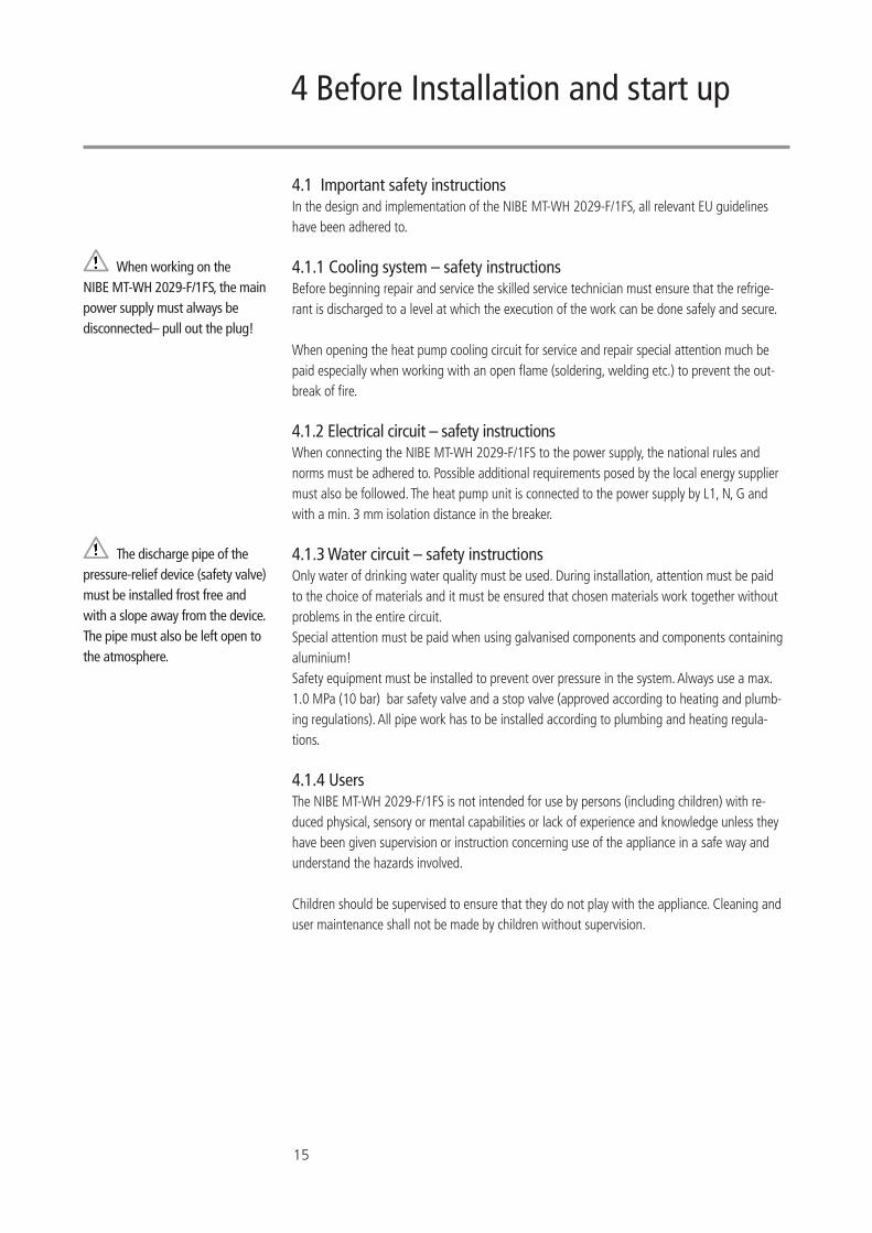
When working on the NIBE MT-WH 2029-F/1FS, the main power supply must always be disconnected– pull out the plug!
The discharge pipe of the pressure-relief device (safety valve) must be installed frost free and with a slope away from the device. The pipe must also be left open to the atmosphere.
4.1 Important safety instructionsIn the design and implementation of the NIBE MT-WH 2029-F/1FS, all relevant EU guidelines have been adhered to.
4.1.1 Cooling system – safety instructionsBefore beginning repair and service the skilled service technician must ensure that the refrige-rant is discharged to a level at which the execution of the work can be done safely and secure.
When opening the heat pump cooling circuit for service and repair special attention much be paid especially when working with an open flame (soldering, welding etc.) to prevent the out-break of fire.
4.1.2 Electrical circuit – safety instructionsWhen connecting the NIBE MT-WH 2029-F/1FS to the power supply, the national rules and norms must be adhered to. Possible additional requirements posed by the local energy supplier must also be followed. The heat pump unit is connected to the power supply by L1, N, G and with a min. 3 mm isolation distance in the breaker.
4.1.3 Water circuit – safety instructionsOnly water of drinking water quality must be used. During installation, attention must be paid to the choice of materials and it must be ensured that chosen materials work together without problems in the entire circuit.Special attention must be paid when using galvanised components and components containing aluminium!Safety equipment must be installed to prevent over pressure in the system. Always use a max. 1.0 MPa (10 bar) bar safety valve and a stop valve (approved according to heating and plumb-ing regulations). All pipe work has to be installed according to plumbing and heating regula-tions.
4.1.4 UsersThe NIBE MT-WH 2029-F/1FS is not intended for use by persons (including children) with re-duced physical, sensory or mental capabilities or lack of experience and knowledge unless they have been given supervision or instruction concerning use of the appliance in a safe way and understand the hazards involved. Children should be supervised to ensure that they do not play with the appliance. Cleaning and user maintenance shall not be made by children without supervision.
16
The domestic hot water heat pump must only be installed by trained personel and in accordance with the local building codes.
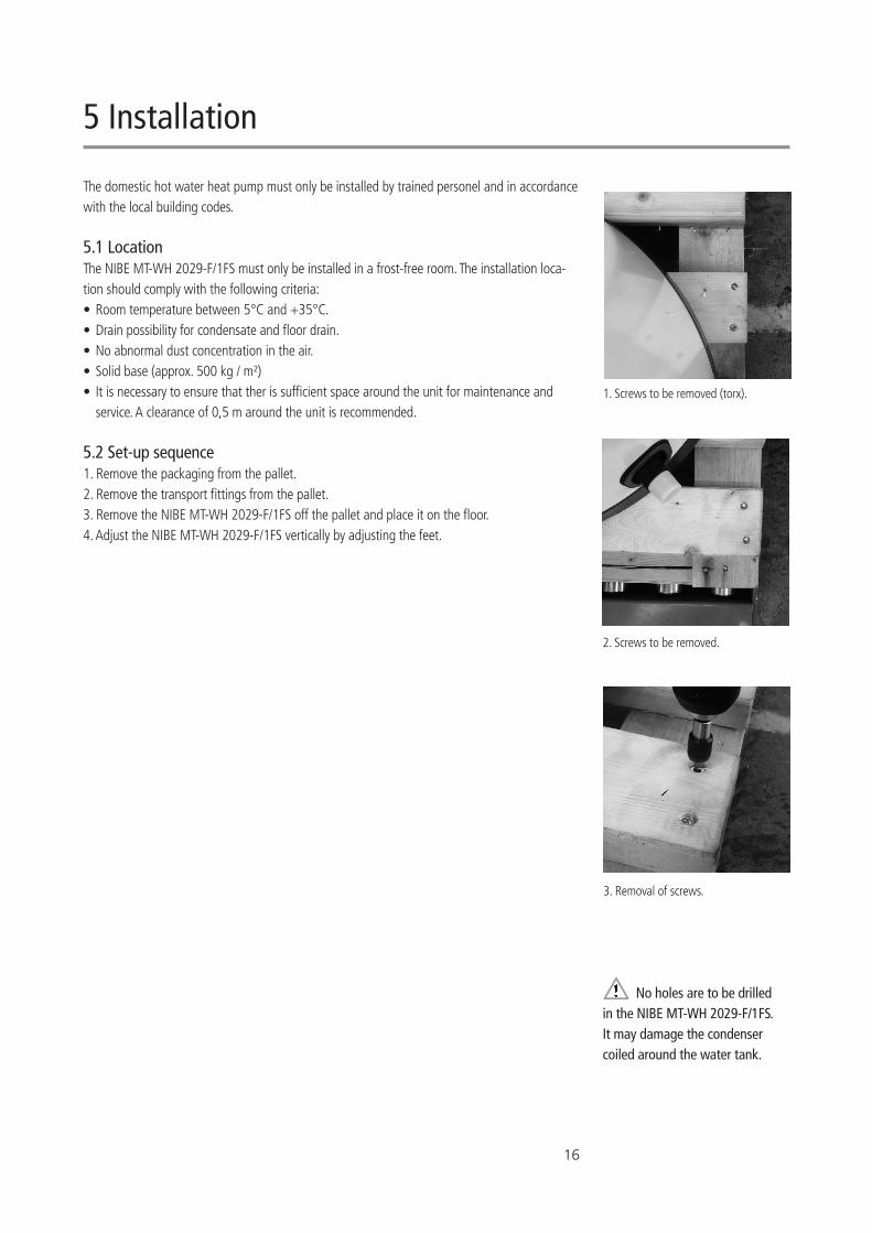
5.1 LocationThe NIBE MT-WH 2029-F/1FS must only be installed in a frost-free room. The installation loca-tion should comply with the following criteria: • Room temperature between 5°C and +35°C. • Drain possibility for condensate and floor drain. • No abnormal dust concentration in the air. • Solid base (approx. 500 kg / m²) • It is necessary to ensure that ther is sufficient space around the unit for maintenance and service. A clearance of 0,5 m around the unit is recommended.
5.2 Set-up sequence1. Remove the packaging from the pallet. 2. Remove the transport fittings from the pallet. 3. Remove the NIBE MT-WH 2029-F/1FS off the pallet and place it on the floor. 4. Adjust the NIBE MT-WH 2029-F/1FS vertically by adjusting the feet.
5 Installation
No holes are to be drilled in the NIBE MT-WH 2029-F/1FS. It may damage the condenser coiled around the water tank.
1. Screws to be removed (torx).
2. Screws to be removed.
3. Removal of screws.
17
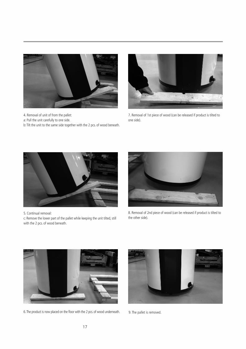
6. The product is now placed on the floor with the 2 pcs. of wood underneath. 9. The pallet is removed.
5. Continual removal:c: Remove the lower part of the pallet while keeping the unit tilted, still with the 2 pcs. of wood beneath.
4. Removal of unit of from the pallet:a: Pull the unit carefully to one side.b: Tilt the unit to the same side together with the 2 pcs. of wood beneath.
7. Removal of 1st piece of wood (can be released if product is tilted to one side).
8. Removal of 2nd piece of wood (can be released if product is tilted to the other side).
18
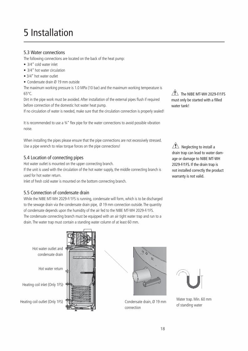
Heating coil inlet (Only 1FS)
Heating coil outlet (Only 1FS)
Hot water outlet and condensate drain
Water trap. Min. 60 mm of standing water
Condensate drain, Ø 19 mm connection
Hot water return
5.3 Water connectionsThe following connections are located on the back of the heat pump: • 3/4” cold water inlet • 3/4” hot water circulation • 3/4” hot water outlet • Condensate drain Ø 19 mm outside The maximum working pressure is 1.0 MPa (10 bar) and the maximum working temperature is 65°C.Dirt in the pipe work must be avoided. After installation of the external pipes flush if required before connection of the domestic hot water heat pump.If no circulation of water is needed, make sure that the circulation connection is properly sealed!
It is recommended to use a ¾” flex pipe for the water connections to avoid possible vibration noise.
When installing the pipes please ensure that the pipe connections are not excessively stressed. Use a pipe wrench to relax torque forces on the pipe connections!
5.4 Location of connecting pipesHot water outlet is mounted on the upper connecting branch.If the unit is used with the circulation of the hot water supply, the middle connecting branch is used for hot water return.Inlet of fresh cold water is mounted on the bottom connecting branch.
5.5 Connection of condensate drainWhile the NIBE MT-WH 2029-F/1FS is running, condensate will form, which is to be discharged to the sewage drain via the condensate drain pipe, Ø 19 mm connection outside. The quantity of condensate depends upon the humidity of the air fed to the NIBE MT-WH 2029-F/1FS.The condensate connecting branch must be equipped with an air tight water trap and run to a drain. The water trap must contain a standing water column of at least 60 mm.
Neglecting to install a drain trap can lead to water dam-age or damage to NIBE MT-WH 2029-F/1FS. If the drain trap is not installed correctly the product warranty is not valid.
The NIBE MT-WH 2029-F/1FS must only be started with a filled water tank!
5 Installation
19
5.6 Air intake, air exhaust and connectionsMake sure that there is sufficient space around the NIBE MT-WH 2029-F/1FS.
The inlet air must not be polluted with aggressive components (ammonia, sulphur, chlorine etc.) as components parts of the heat pump unit may be damaged. The air also needs to be free of dust and other particles.Inlet and outlet ducts must be made of rigid smooth pipes to minimize pressure losses. Please take into account the fan working pressure and the ducts pressure losses during dimensioning of the duct system (see technical data).The two connections to the heat pump are Ø 160 m.It is advised to install the air ducts near the heat pump, levelled or with a slight slope away from the air in- and outlet to avoid ingress of condensed water from the duct system to the heat pump.When air ducts are connected to the outside of a building, a low resistance non return flap should be installed to ensure that no cold air is entering the room during winter times when the heat pump is not operating.
All air ducts have to be insulated after they have been installed to reduce heat loss and noise level. Insulation has to be applied to protect against external condensation on the cold exhaust duct.
It is recommended to mount a flexible connection between the air duct and duct connection to ease future service of the unit.It is also recommended to install silencer units in between the heat pump unit and the ventila-tion system to avoid potential travel of noise from the unit to the ventilation system.
5.7 Connection of NIBE MT-WH 2029-1FS heating coilIn the NIBE MT-WH 2029-1FS there is an extra heat exchanger installed (1” coil, 1.2 m²). In the sensor pocket for the thermostat sensor there can also be placed a sensor to control the external connection e.g. oil burner, wood burner etc. Max. diameter of the sensor is 6 mm. The maximum inlet temperature of the heating coil is 90 °C. If there is risk of inlet temperatures above 90 °C the installer must install an external device preventing high temperature inlets to the heating coil.
Dirt in the pipe work must be avoided. After installation of the external pipes. Flush if required before connection of the domestic hot water heat pump.
When installing the pipes please ensure that the pipe connections are not excessively stressed. Use a pipe wrench to relax torque forces on the pipe connections!
Do not drill any holes for fittings etc. in the unit. This could potential damage the product causing it to be having to be scrapped.
The NIBE MT-WH 2029-F/1FS must always be disconnected from the power before the top cover of the unit is removed!When the unit is disconnected from the power, please wait until the fan has stopped before dismantling the top cover!
Temperatures above 90 °C in the heating coil may cause excessive pressures in the cooling circuit.
20
6 Commissioning
6.1 Leak testAfter installation it is necessary to check that the entire water installation is tight. This is accom-plished by performing a water leak test. Also check that the drain water trap on the condense water hose/pipe has a min. height of 60 mm and that the drainage is unobstructed.
6.2 Commissioning of the water circuitFill the water tank via the cold water connecting branch. Deaerate the water tank by opening one of the hot water taps located at the highest level until air no longer appears at the tapping point.
6.3 Commissioning of the air circuitEnsure that the air in- and outlet paths are open and ready for use.
6.4 Commissioning of the electrical circuitPower up the unit. A counter displays the numbers 1 to 9 followed by display of the controller model (170) for 3 sec. and the software version for 3 sec. Then the top of water tank tempera-ture is displayed and the unit engages operation.
The NIBE MT-WH 2029-F/1FS is now ready for use.
21
7 Controls and Operations
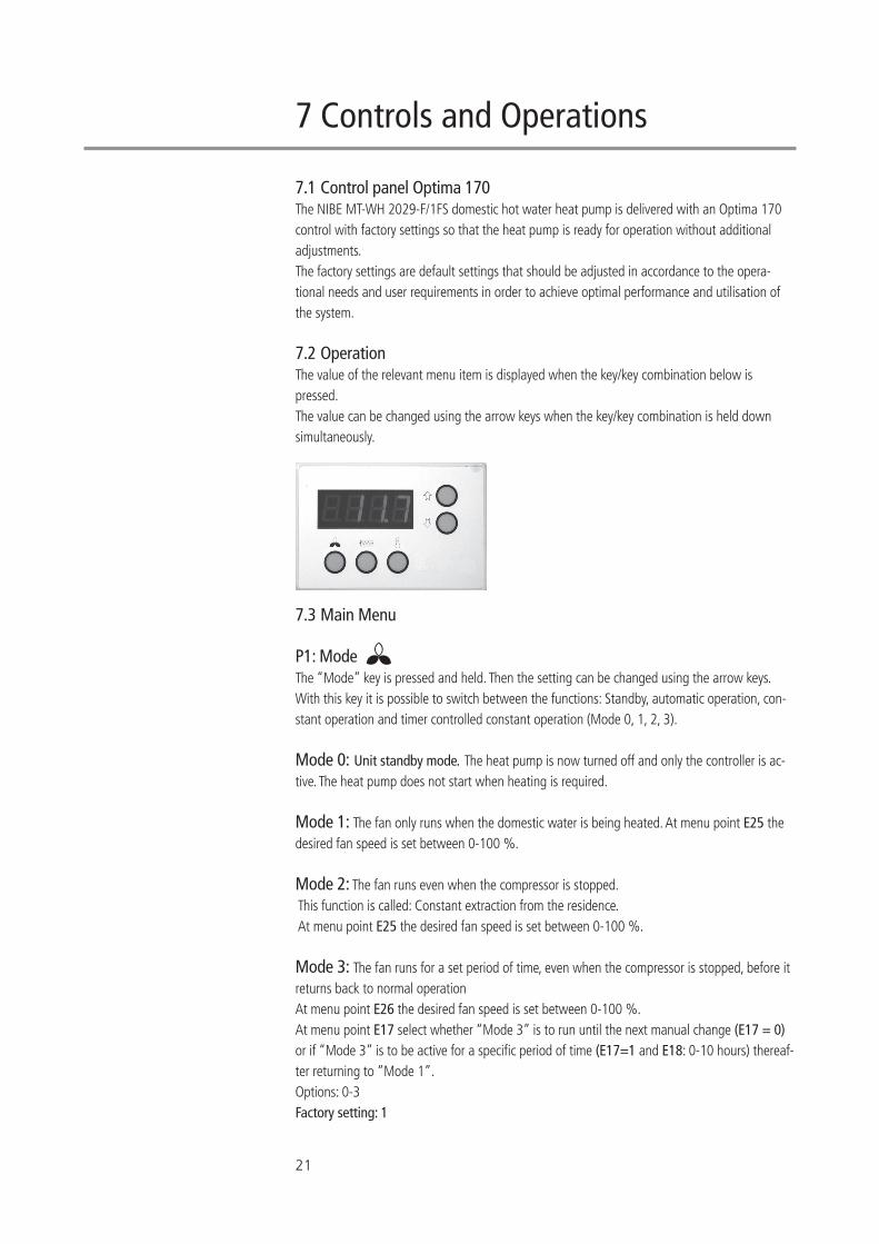
7.1 Control panel Optima 170 The NIBE MT-WH 2029-F/1FS domestic hot water heat pump is delivered with an Optima 170 control with factory settings so that the heat pump is ready for operation without additional adjustments. The factory settings are default settings that should be adjusted in accordance to the opera-tional needs and user requirements in order to achieve optimal performance and utilisation of the system.
7.2 OperationThe value of the relevant menu item is displayed when the key/key combination below is pressed. The value can be changed using the arrow keys when the key/key combination is held down simultaneously.
7.3 Main Menu
P1: Mode The “Mode” key is pressed and held. Then the setting can be changed using the arrow keys. With this key it is possible to switch between the functions: Standby, automatic operation, con-stant operation and timer controlled constant operation (Mode 0, 1, 2, 3).
Mode 0: Unit standby mode. The heat pump is now turned off and only the controller is ac-tive. The heat pump does not start when heating is required.
Mode 1: The fan only runs when the domestic water is being heated. At menu point E25 the desired fan speed is set between 0-100 %.
Mode 2: The fan runs even when the compressor is stopped. This function is called: Constant extraction from the residence. At menu point E25 the desired fan speed is set between 0-100 %.
Mode 3: The fan runs for a set period of time, even when the compressor is stopped, before it returns back to normal operationAt menu point E26 the desired fan speed is set between 0-100 %. At menu point E17 select whether “Mode 3” is to run until the next manual change (E17 = 0) or if “Mode 3” is to be active for a specific period of time (E17=1 and E18: 0-10 hours) thereaf-ter returning to “Mode 1”. Options: 0-3Factory setting: 1
22
P2: Controlling the electrical immersion heater The “immersion heater”-key is pressed and held. Then the setting can be changed with the arrow keys.The heat pump is supplied with an electrical immersion heater for heating of the domestic water.At outside temperatures below 0°C it may be beneficial to use the immersion heater as a sup-plement for heating the domestic water. 0 = the immersion heater is not in operation, even when needed. 1 = the immersion heater is in operation when needed (see set point P5). 2 = The heat pump is not in operation, only the emersion heater (see set point P5).Options: 0-2 Factory setting: 0
P3: Operating thermostat The “operating thermostat”-key is pressed and held. Then the setting can be changed with the arrow keys. Domestic water is heated by the heat pump. The compressor starts if the T8 temperature (hot water tank, bottom) becomes lower than set point P3 minus 5°C. The compressor stops again when the T8 temperature is equal to set point P3. Options: 0-55 °C Factory setting: 52 °C
P4: Stop defrosting The “Mode”+ “Operating thermostat” keys are pressed and held simultaneously. Then the set-ting can be changed with the arrow keys.The defrosting cycle normally stops when the evaporator has reached a temperature of 10°C. Under special conditions it may be necessary to change this temperature setting. Options: 0-25 °C Factory setting: 10 °C
P5: Electrical immersion heater “Immersion heater”+ “Operating thermostat” keys are pressed and held simultaneously. Then the setting can be changed with the arrow keys.The electrical immersion heater only heats the upper half of the water tank, while the heat pump continues heating the bottom part of the water tank. The electrical immersion heater activates if the T7 temperature (water tank top) is lower than set point P5 minus 5°C. The electrical immersion heater stops again when the T7 temperature is higher than set point P5. Options: 0-65 °CFactory setting: 50 °C
7 Control and Operations
23
7.3.1 Display view (main menu) The display show the various temperatures by pressing the arrow keys. Press until the number of the sensor of the desired temperature appears. After approximately 3 seconds the temperature is displayed. The relevant temperature is displayed for about 30 seconds before the display goes back to normal view. Normal view is set at menu point E49 (blank display, water temperature T7 or clock).
The following values can be displayed: T5: Before evaporatorT6: EvaporatorT7: Water tank, top T8: Water tank, bottom T9: Additional sensor (can be used e.g. as solar collector temperature sensor)T10 “External start/stop” input (cannot be used for temperature display). When T10 is short circuited, the heat pump goes into forced operation. CL: The current time from the built-in clock.
7.4 Service menu
7.4.1 Changing settings in the service menu Press the “Arrow up” and “Arrow down” simultaneously for approximately 10 seconds to enter the service menu. The display now shows the first menu item E0 in the service menu. If a key is not activated for about 15 seconds while in the service menu, the service menu shuts down automatically and the control returns to the main menu. A desired menu item E# can be reached by scrolling up and down with the “Arrow up” and “Arrow down” keys. The value of the menu item is displayed when you press the “Operating thermostat”-key ( ). The value can be changed using “Arrow Up” and “Arrow down” keys, when the “Operating thermostat”-key is pressed simultaneously. When the desired value is reached, release the “Operating thermostat”-key and you will return to menu item E#.
7.4.2 Service menu points
E0: Factory settings If the set points are adjusted so that the system does not work as expected and the cause cannot be found, do as follows: 1. Write down all the set points in the “table for set points” (elsewhere in this manual). 2. Adjust the set point to 1 and wait until the control goes back to normal view. The value “E99” will show shortly to confirm factory reset.3. Now all the set points have been changed to the factory settings. 4. You can now start from scratch and the set points can be adjusted. Options: 0-1Factory setting: 0
24
E2: T9 temperature set point Here a temperature can be set which can be used in connection with menu item E19 and tem-perature sensor T9. This is a separate sensor, which is not part of standard delivery. See E19=2, 4 or 5 for further description. Options: 0-30°C Factory setting: 21°C
E6: Anti-legionella - week dayHere the week day for anti-legionella control is set, if the function is activated in E8.Options: 1-7 daysFactory setting: 1 day
E7: Anti-legionella – start timeHere the start time for anti-legionella control is set, if the function is activated in E8.Options: 0-23 hoursFactory setting: 2 hours
E8: Anti-legionella function If the value is set to 1, the water will be heated to 65°C with the help of the electrical immersion heater once a week to disinfect the water tank. If the value is set to 0, the disinfection function is turned off. Please note, the anti-legionella function is active when selected even if the unit is in standby mode (P1=0) in order to avoid bacteria growth.Options: 0-1Factory setting: 0
E9: Operating in cold surroundings ON/OFFValue of 0: If the inlet air temperature (T5) is colder than the value set at menu point E10, the compressor will stop and the electrical immersion heater activated automatically when required (P5 and temperature sensor T7). The compressor can start again if the intake air temperature (T5) has been higher than the temperature set at menu point E10 for 30 minutes.Value of 1: If the inlet air temperature (T5) is colder than the value set at menu point E10, the compressor will not stop, but the electrical immersion heater is activated automatically when required (P5 and temperature sensor T7). Options: 0-1 Factory setting: 0
E10: Operating in cold surroundings temperatureHere the temperature is set determining when the compressor is disengaged or when the immersion heater is engaged. See menu item E9. Options: -5-10 °C Factory setting: 0 °C
7 Control and Operations
25
E13: Floor heating temperature Here a temperature is set, which can be used in connection with menu item E19=2, i.e., the minimum temperature, at which the circulation pump for the floor heating starts. If the tempera-ture T8 (water tank, bottom) is less than the value set at menu point E13, the circulation pump stops. Options: 20-50 °C Factory setting: 35 °C
E15: External start / stop control Value of 0: The control switches to P1, mode 3, if input T10 (External start / stop) is short circuit-ed. When T10 is interrupted again, the controller goes back to the mode, prior to short circuiting. This function can be used by an external hygrostat which, at high humidity, can force the system to mode 3. Value of 1: The control switches to P1, mode 0 (unit standby) if input T10 (External start/stop) is short circuited. When T10 is interrupted again, the controller goes back to the mode, prior to short circuiting. This function can be used for simple external control of the heat pump unit, e.g., simple start/stop control from a potential free contact in a solar PV inverter.Value of 2: PV mode. External control of the unit via variable voltage input to T10. Please see menu points E30 to E32 for control details.Input T10 requires a 0-3VDC signal. Special cables can be supplied for conversion of a 0-10 VDC signal or a 4-20mA signal.Options: 0-2Factory setting: 0
E16: Minimum air flowThis value specifies the minimum air flow, which the fan should provide during operation. Please be aware that the cooling system may be overloaded resulting in the high pressure switch alarm if this value is set too high. The value should not be chosen higher than necessary to ensure a minimum air flow through the evaporator. Options: 0-100 %Factory setting: 15 %
E17: Forced operation ON If P1 is set to mode 3, there is a possibility that the system automatically switches to mode 1 after the number of hours set at menu point E18. Value of 0: The system runs in P1 mode 3, until it is manually changed to a different step. Value of 1: System returns to mode 1 after the number of hours set at menu point E18. Options: 0-1Factory setting: 0
26
E18: Number of hours Setting of number of hours for continuous run at fan speed mode 3 before automatically switch-ing back to mode 2. This option is used by the menu item E17=1. Options: 1-10 hoursFactory setting: 3 hours
E19: Extra function This function controls relay R9: Solar collector, additional heat sources, heat sink, or damper control. Options: 0-1Factory setting: 0
Value of 0: This feature is disabled, and the relay is switched off.
Value of 1 (special NIBE MT-WH 2029-1FS coil function): The solar collector function which activates an external solar pump (relay R9). If the T8 temperature (water tank, bottom) is lower than the set point in menu point E46 (max. water tank temperature), the solar pump function is activated. The pump will run if the T9 temperature (solar collector) is higher than the T8 temperature (wa-ter tank, bottom) + menu item E20 (solar collector hysteresis). The pump stops again when the T9 temperature (solar collector) becomes lower than the T8 temperature (water tank, bottom). This feature is independent of the heat pump running status.
Value of 2 (special NIBE MT-WH 2029-1FS coil function): The floor heating function which activates an external circulation pump (relay R9). If the T8 temperature (water tank, bottom) is higher than the setting at menu point E13 (floor heating temperature), the floor heating func-tion is activated. The pump will run, if the T9 temperature (external sensor) is lower than the set point in menu point E2. The pump (relay R9) stops again when the T9 temperature (external sensor) is higher than the setting at menu point E2. This feature is independent of the heat pump running status.
Value of 3 (special NIBE MT-WH 2029-1FS coil function): The solar collector function which activates the solar pump (relay R9). The solar collector function has an overall safety feature that can turn off the solar pump. If the T9 temperature (solar collector) is higher than 89 °C, the pump is turned off. The pump starts again if the T9 temperature (solar collector) is less than 87 °C. If the T8 temperature (water tank, bottom) is less than the set point in menu point E46 (max. water tank temperature), the solar pump function is activated. The pump will run if the T9 temperature (solar collector) is higher than the T8 temperature (wa-ter tank, bottom) + menu item E20 (solar collector hysteresis). The pump (relay R9) stops again when the T9 temperature (solar collector) becomes lower than the T8 temperature (water tank, bottom).
7 Control and Operations
27
When the pump (relay R9) is activated, the heat pump and the electrical immersion heater switches off. After the pump (relay R9) is deactivated the following happens after 15 min: • If the T5 temperature (before evaporator) is greater than 5.5 °C, the heat pump is activated. • If the T5 temperature (before evaporator) is lower than 4.5 °C, the electrical immersion heater is activated.
Value of 4: The cooling function which activates a three-way damper, which directs the cold exhaust air to a room with cooling requirements. This feature is controlled by the temperature set point in menu point E2 and the T9 sensor: • If the T9 temperature is higher than the set point at menu point E2, relay R9 switches on. • If the T9 temperature is lower than the set point at menu point E2, relay R9 switches off. This feature is independent of the heat pump running status. Value of 5: The cooling function which activates a three-way damper, which directs the cold exhaust air to a room with cooling requirements. This feature is controlled by the temperature set point at menu point E2 and the T9 sensor, but works opposite of menu item E19 = 4: • If the T9 temperature is higher than set point at menu point E2, relay R9 switches off. • If the T9 temperature is lower than set point at menu point E2, relay R9 switches on. This feature is independent of the heat pump running status.
Value 6: Relay R9 is ON, if the compressor is running and OFF if it is not running.This feature is independent of the heat pump running status. Options: 0-6Factory setting: 0
E20: Solar collector hysteresis Here it can set how much the temperature in the solar collector (T9) has to be above the tem-perature in the water tank (T8), before the solar pump is to start. See menu item E19. Options: 1-5 °CFactory setting: 5 °C
E21: TX set point In order to avoid high operating pressures in the cooling system it is necessary to reduce the performance of the system for the last part of the heating cycle. Here the water temperature (T8) is set at which the reduction must begin. Options: 0-55 °C. Factory setting: 45 °C.
E23: Tmop This value specifies the maximum evaporator temperature (T6) allowed. This prevents overload-ing of the cooling system at high ambient temperatures. Options: 0-30 °CFactory setting: 25 °C
28
E25: Fan speed mode 1 + 2 If extraction of air for a longer period of time is required, mode 2 (P1) can be chosen. The fan will now run, until it is change to a different mode. Enter the speed, at which the fan is to run when mode 2 is chosen. Please note that this option also restricts the maximum speed of the fan in mode 1. Options: 0-100 %Factory setting: 100 %
E26: Fan speed mode 3 Enter the speed, at which the fan is to run when mode 3 (P1) is chosen. This option is selected if forced extraction from the house for a limited period of time is required. Options: 0-100 %Factory setting: 100 %
E30: PV control of immersion heaterThe percentage of T10 input voltage at which the electrical immersion heater engages. If the input is higher than the set-point the immersion heater is on. If the input value falls below the immersion heater turns off after 2 minutes. If this value is set to 0 the PV control of the immer-sion heat is inactivated.Please see the figure below for conversion of input signals.Options: 0-100 %Factory setting: 0 %
E31: PV control of heat pumpThe percentage of T10 input voltage at which the heat pump/compressor engages. If the input is higher than the set-point the heat pump starts after the threshold time set in E32. Once the heat pump has been engaged in PV mode the compressor will run for at least 30 min in order to avoid excessive wear in the compressor. If this value is set to 0 the PV control of the heat pump/compressor is inactivated.Please see the figure below for conversion of input signals.Options: 0-100 %Factory setting: 0 %
7 Control and Operations
29
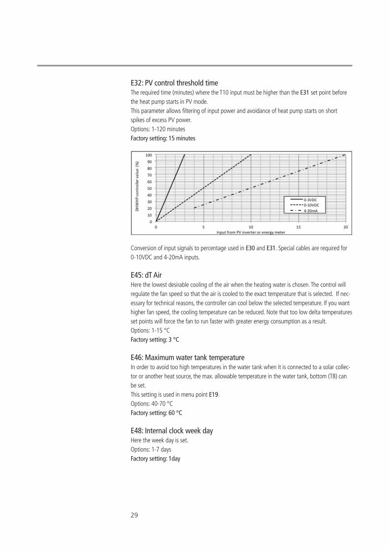
E32: PV control threshold timeThe required time (minutes) where the T10 input must be higher than the E31 set point before the heat pump starts in PV mode.This parameter allows filtering of input power and avoidance of heat pump starts on short spikes of excess PV power.Options: 1-120 minutesFactory setting: 15 minutes
Conversion of input signals to percentage used in E30 and E31. Special cables are required for 0-10VDC and 4-20mA inputs.
E45: dT Air Here the lowest desirable cooling of the air when the heating water is chosen. The control will regulate the fan speed so that the air is cooled to the exact temperature that is selected. If nec-essary for technical reasons, the controller can cool below the selected temperature. If you want higher fan speed, the cooling temperature can be reduced. Note that too low delta temperatures set points will force the fan to run faster with greater energy consumption as a result. Options: 1-15 °CFactory setting: 3 °C
E46: Maximum water tank temperature In order to avoid too high temperatures in the water tank when it is connected to a solar collec-tor or another heat source, the max. allowable temperature in the water tank, bottom (T8) can be set. This setting is used in menu point E19. Options: 40-70 °CFactory setting: 60 °C
E48: Internal clock week dayHere the week day is set.Options: 1-7 daysFactory setting: 1day
30
7 Control and Operations
E49: Screen saverHere you can select the screen saver: 1: Blank display. A point flashes to show that the system is powered. 2: Water temperature T7 (water tank, top) is displayed. 3: The time is displayed. Options: 1-3Factory setting: 2
E50: Internal clock hoursHere the hours of the clock are set. Options: 0-23 hoursFactory setting: 0 hours
E51: Internal clock minutes Here the minutes of the clock are set. Options: 0-59 minutesFactory setting: 0 minutes
E52: Low tariff period ON/OFFValue of 0 (OFF): The electrical immersion heater and the heat pump will run according to need and preferences. Value of 1 (ON): The electrical immersion heater and the heat pump will only run during to the specified period of time with the start according to menu item E53 and end according to menu item E54. Please note, if PV mode is selected (E15=2) this allows the immersion heater and the heat pump to run outside the low tariff period if PV power is available.Options: 0-1Factory setting: 0
E53: Low tariff period start time - working daysThe start time of a low electricity tariff period during working days (day 1-5) is set here. Options: 0-23 hoursFactory setting: 1 hour
E54: Low tariff period stop time - working daysThe stop time of a low electricity tariff period during working days (day 1-5) is set here. Options: 0-23 hoursFactory setting: 6 hours
E55: Low tariff period start time - weekendsThe start time of a low electricity tariff period during weekends (day 6-7) is set here. Options: 0-23 hoursFactory setting: 1 hour
31
E56: Low tariff period stop time – weekendsThe stop time of a low electricity tariff period during weekends (day 6-7) is set here. Options: 0-23 hoursFactory setting: 6 hours
E60: Temperature difference between T5 and T6 If the T6 temperature (evaporator) is higher than the T5 temperature (before evaporator) + the value set in menu point E-0 after one hour with the compressor in operation, the compressor will turn off. “Er6” will show in the display. This is an operational safety feature which indicates that the heat pump is not running properly, potentially lacking refrigerant. The unit has to be turned off to reset the error. Options: 0-10 °CFactory setting: 2 °C
32
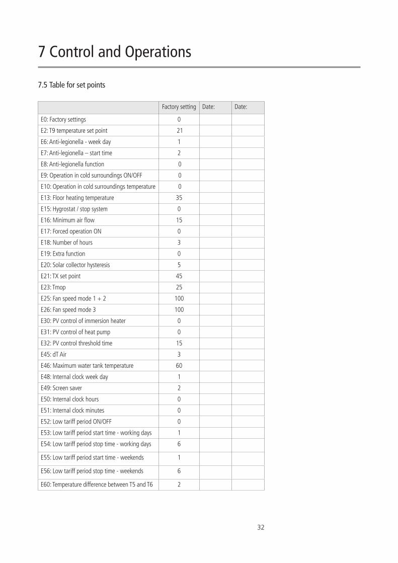
7.5 Table for set points
Factory setting Date: Date:
E0: Factory settings 0
E2: T9 temperature set point 21
E6: Anti-legionella - week day 1
E7: Anti-legionella – start time 2
E8: Anti-legionella function 0
E9: Operation in cold surroundings ON/OFF 0
E10: Operation in cold surroundings temperature 0
E13: Floor heating temperature 35
E15: Hygrostat / stop system 0
E16: Minimum air flow 15
E17: Forced operation ON 0
E18: Number of hours 3
E19: Extra function 0
E20: Solar collector hysteresis 5
E21: TX set point 45
E23: Tmop 25
E25: Fan speed mode 1 + 2 100
E26: Fan speed mode 3 100
E30: PV control of immersion heater 0
E31: PV control of heat pump 0
E32: PV control threshold time 15
E45: dT Air 3
E46: Maximum water tank temperature 60
E48: Internal clock week day 1
E49: Screen saver 2
E50: Internal clock hours 0
E51: Internal clock minutes 0
E52: Low tariff period ON/OFF 0
E53: Low tariff period start time - working days 1
E54: Low tariff period stop time - working days 6
E55: Low tariff period start time - weekends 1
E56: Low tariff period stop time - weekends 6
E60: Temperature difference between T5 and T6 2
7 Control and Operations
33
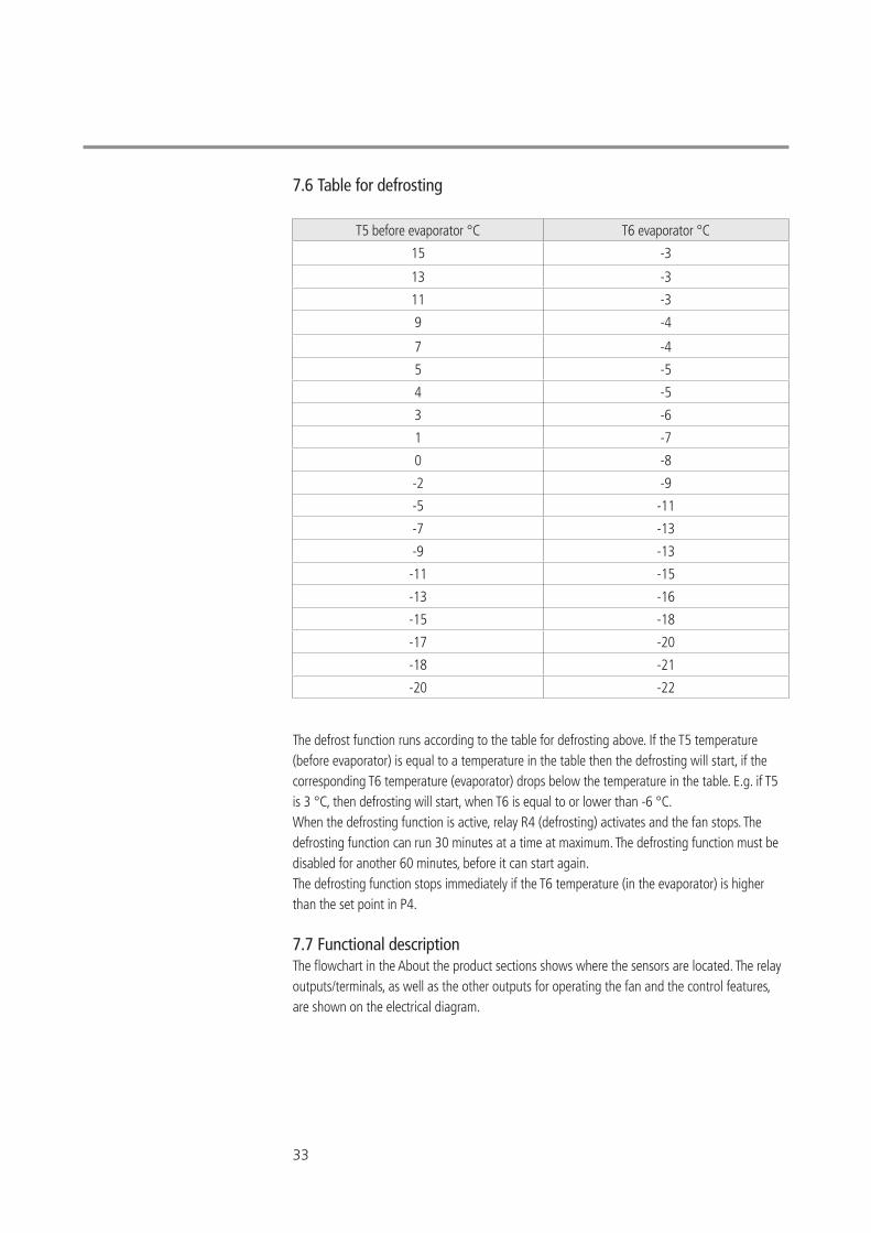
7.6 Table for defrosting
The defrost function runs according to the table for defrosting above. If the T5 temperature (before evaporator) is equal to a temperature in the table then the defrosting will start, if the corresponding T6 temperature (evaporator) drops below the temperature in the table. E.g. if T5 is 3 °C, then defrosting will start, when T6 is equal to or lower than -6 °C. When the defrosting function is active, relay R4 (defrosting) activates and the fan stops. The defrosting function can run 30 minutes at a time at maximum. The defrosting function must be disabled for another 60 minutes, before it can start again. The defrosting function stops immediately if the T6 temperature (in the evaporator) is higher than the set point in P4.
7.7 Functional descriptionThe flowchart in the About the product sections shows where the sensors are located. The relay outputs/terminals, as well as the other outputs for operating the fan and the control features, are shown on the electrical diagram.
T5 before evaporator °C T6 evaporator °C
15 -3
13 -3
11 -3
9 -4
7 -4
5 -5
4 -5
3 -6
1 -7
0 -8
-2 -9
-5 -11
-7 -13
-9 -13
-11 -15
-13 -16
-15 -18
-17 -20
-18 -21
-20 -22
34
7.7.1 Controlling Domestic hot water heat pump with Optima 170The domestic hot water heat pump is a complete unit with a 285 litre hot water tank, fan, heat pump and complete automation. The unit is used exclusively for heating domestic water within the set temperature limit. Auxiliary function for supplying a small floor heating unit or for alter-native heat input is available in the NIBE MT-WH 2029-F/1FS S model.
7.7.2 Performance The domestic hot water heat pump can heat 367 litres of water from 10 °C to 52.5 °C within 11.5 hours at an extract air temperature of 7°C. The heating time always depends on the temperature of the cold water supplied to the water tank, the extract air temperature and the tapping pattern. The electrical immersion heater of 1.5 kW can be activated if there is a need for extra hot water. The domestic hot water heat pump only consumes approximately 28% power compared to a conventional electrical water heater.
7.7.3 The function of the heat pump The control starts the compressor shortly after hot water has been tapped. The compressor runs until the whole water tank has reached the set temperature. Normally, the domestic hot water heat pump is able to produce enough hot water to cover an entire family’s hot water consump-tion.
7.7.4 Water heating When tapping hot water, cold water is supplied to bottom of the water tank. A sensor measures the temperature in the bottom of the water tank. When the temperature has dropped 5°C be-low the set temperature, the compressor starts and the fan ventilates air through the evaporator. When the water is heated to the set temperature, the compressor (and fan) stops again.
7.7.5 Fan operation The fan can continue to run, even when the compressor has stopped. Select mode 2 or mode 3. These functions are used when a domestic hot water heat pump also is used for extracting air from wet rooms in the residence. As long as input to T10 (External start/stop) is short circuited, the control is forced to run mode 3. This can be used to ensure additional extraction from e.g. the bathroom while taking a show-er. When the input to T10 is no longer short circuited, the controller will go back to the mode prior to short circuiting.
7.7.6 DefrostingWhen ice formation occurs on the evaporator, the temperature difference between the tempera-ture before the evaporator and the temperature in the evaporator is too high and the system will begin the defrost cycle (see table for defrosting). The solenoid valve (MA4) opens and the fan stops, until the ice has melted and the evaporator has reached a temperature of approximately 10 °C (subject to the set point in menu point P4). Then the solenoid valve closes again and the fan starts.
7 Control and Operations
35
7.7.7 Extra heating capacity If a situation arises where the domestic hot water heat pump is not able to provide enough hot water, it is possible to activate the built-in electrical immersion heater. About twice as much water can now be heated in the same period of time. You can set the temperature to which the electrical immersion heater is to heat the water. Only use the electrical immersion heater if necessary. The electrical immersion heater consumes more energy than the compressor. The electrical immersion heater can be activated manually on the control panel.
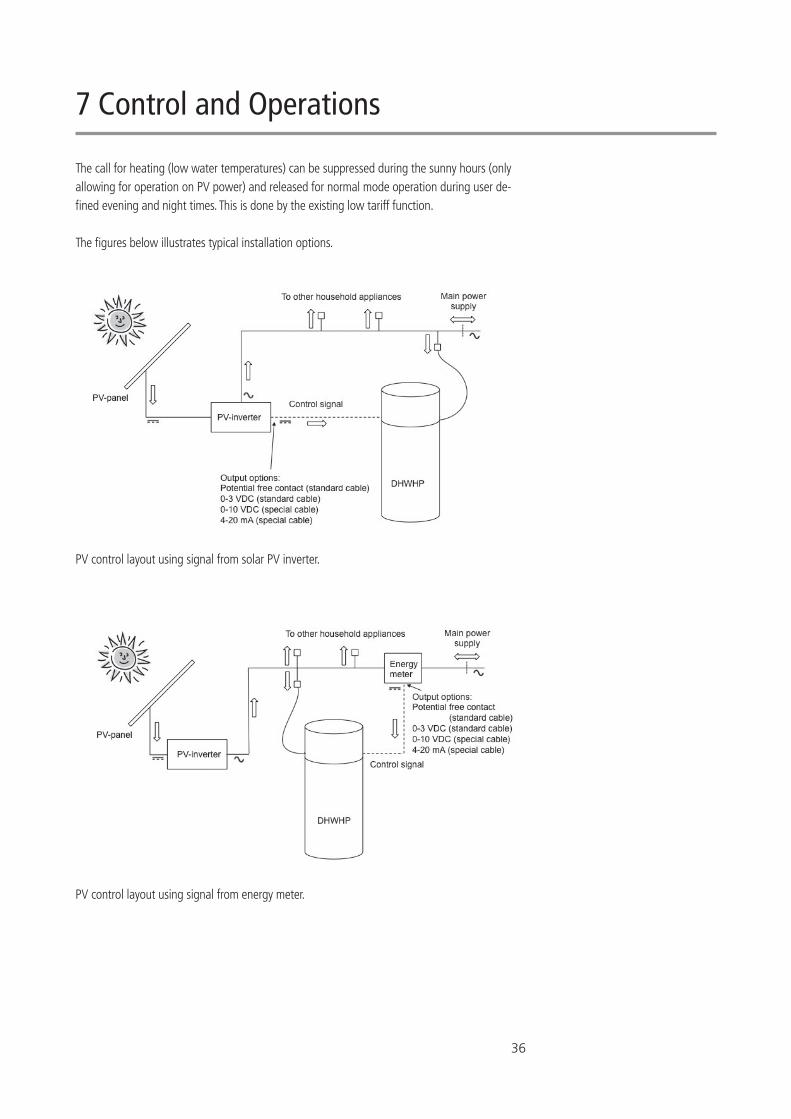
7.7.8 Photovoltaic functionThe domestic hot water heat pump (DHWHP) can be controlled by a signal from a solar photo-voltaic (PV) converter or an energy meter, either as simple start/stop via a potential free contact or by a variable signal.
Using the variable signal option, a certain output (DC or mA) from the (PV) inverter or the en-ergy meter corresponds to a given amount of excess power for use in the DHWHP. This excess power can be used to activate either the electrical immersion heater, the heat pump (HP) or both.
36
The call for heating (low water temperatures) can be suppressed during the sunny hours (only allowing for operation on PV power) and released for normal mode operation during user de-fined evening and night times. This is done by the existing low tariff function.
The figures below illustrates typical installation options.
PV control layout using signal from solar PV inverter.
PV control layout using signal from energy meter.
7 Control and Operations
37
Disconnect the power to the unit before carrying out any repairs on the unit. Repair of the unit and reactivation of safety breakers should only be carried out by authorized person-nel.
7.7.9 Timer functionThe timer function includes a 24 hours clock plus week days (1-7). Two different low tariff periods can be defined, working days and weekends. Also, the day and time for anti-legionella control can be set.
7.8 Safety features
7.8.1 High pressure switch In order to ensure that the compressor does not run beyond its operating envelope there is a built-in high pressure switch which shuts down the compressor when the pressure in the cooling circuit becomes too high. The pressure switch shuts down the compressor if the pressure gets higher than 2.0 MPa (20 bar) and reengage the compressor when pressure has lowered to 1.6 MPa (16 bar).
7.8.2 Safety breakersIn the event of a failure on the electrical immersion heater, the safety breakers will shut down the unit. If the set value (80°C) is exceeded, the electrical immersion heater will disconnect. The electrical immersion heater can be reactivated when the temperature is below 80°C. To do this, the power to the unit must be switched off and the front panel dismantled. Then the reset but-tons in the centre of the breakers can be pressed.
The compressor is also equipped with a thermal circuit protector, ensuring that the compressor stops if the temperature gets too high. For an example if the compressor does not revolve when powered, due to blockage or due to lack of pressure equilisation before start-up. If the breaker cuts out the compressor, leave the unit to cool down before restarting. Upon repeat, call for service personnel.
7.9 Alarms
7.9.1 PE: High pressure switch alarm When the high pressure switch cuts off, the error text ”PE” will show in the display. When the cause of the error is found the power must be switched off for 10 seconds and then turned on again to reactivate the pressure switch. The “PE” error disappears from the display.
Lower the water temperature set point 2-3°C if necessary to avoid the recurrence of the pres-sure switch error.
7.9.2 Er6: Atypical evaporator temperaturesIf the evaporator temperature (T6) is higher than the temperature before the evaporator (T5) + the value set in menu point E60 after one hour with the compressor in operation, the compres-sor will turn off. “Er6” will show in the display. See also section 7.4.2, E60.
38
8 Maintenance
To achieve optimal performance, please observe the points below.
Before the unit is opened, disconnect the power/ unplug and wait until the fan has stopped.
A few days after the initial setup and start-up, check the installation for leaks in the water instal-lation or blockage of the condensate drain.
8.1 Environmental requirements When repairing or dismantling the domestic hot water heat pump please follow the environ-mental regulations and legal requirements in relation to recycling and disposal of materials.
8.2 Cooling system and fanServicing primarily consists of periodic cleaning of the evaporator. Remove the top plate of the unit. Clean the evaporator and fan with a brush or a bottle brush. Be careful not to remove balancing weights on the fan wheel during this process, as this will cause fan imbalance and lead to a higher noise level as well as wear and tear on the fan.
Please observe local rules and regulations regarding potential periodically inspection of the heat pump by skilled personnel.
8.3 Condensation and condensate drain Together with inspecting and cleaning of the fan, the condensate tray shall be cleaned of dirt. Fill water into the condensate tray and check if the water flows freely. If not, then the drain must be cleaned.
8.4 Water circulation and water tank
8.4.1 Pressure relief valve Your installer has installed a pressure relief valve near the cold water connection on the do-mestic hot water tank to protect the water tank against excessive pressures when the domestic water expands during the heating process. The back pressure valve (check valve), which is installed in front of the pressure relief valve on the cold water pipe, prevents water from the tank flowing back into the cold water pipe. There-fore, the pressure in the water tank rises to the maximum setting of the pressure relief valve and the pressure relief valve opens. The redundant water discharges. If the pressure relief valve did not open, the water tank would burst. The pressure relief valve must operated regularly to remove lime deposits and to verifythat it is not blocked. It is tested by pressing the lever/turning the handle on the pressure relief valve while checking that water discharges. Damages due to a faulty pressure relief valve are not covered by the warranty. Please note that water may drip from the discharge pipe of the pressure-relief valve due to heat-ing of the water.
Risk of injury from sharp slats. The slats must not be dam-aged.
39
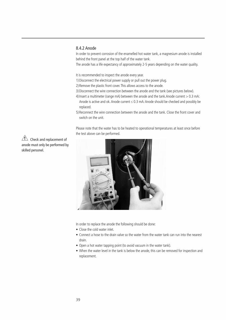
8.4.2 Anode In order to prevent corrosion of the enamelled hot water tank, a magnesium anode is installed behind the front panel at the top half of the water tank. The anode has a life expectancy of approximately 2-5 years depending on the water quality.
It is recommended to inspect the anode every year.1) Disconnect the electrical power supply or pull out the power plug.2) Remove the plastic front cover. This allows access to the anode.3) Disconnect the wire connection between the anode and the tank (see pictures below).4) Insert a multimeter (range mA) between the anode and the tank.Anode current > 0.3 mA: Anode is active and ok. Anode current ≤ 0.3 mA: Anode should be checked and possibly be replaced.5) Reconnect the wire connection between the anode and the tank. Close the front cover and switch on the unit.
Please note that the water has to be heated to operational temperatures at least once before the test above can be performed.
In order to replace the anode the following should be done:• Close the cold water inlet.• Connect a hose to the drain valve so the water from the water tank can run into the nearest drain.• Open a hot water tapping point (to avoid vacuum in the water tank).• When the water level in the tank is below the anode, this can be removed for inspection and replacement.
Check and replacement of anode must only be performed by skilled personel.
40
10 Troubleshooting
10.1 The heat pump does not supply hot waterCheck out the following: • Is the system connected to power? • Is there power at the wall socket? • Is the heat pump switched off via the temperature sensor T8? • Is the water temperature >55 °C?• Is the cold water supply open?• Is there a free access of inlet air?• Is there a free flow path for outlet air?• Has the periodic cleaning of evaporator, condensation tray and fan as described in the Maintenance section been followed?• Has any of the safety features disengaged the heat pump/electrical emersion heater?• Has external shot-circuiting of terminals disengaged the heat pump?• Has factory resetting (E0) been tested?
If it is not one of the above errors, please contact: • In the warranty period (0-2 years): The installer, from which the unit was purchased. • After the warranty period (2 years ->): The installer from which the unit was purchased or NIBE Energy Systems Partners. Please have data from name plate ready (silver plate on the unit).
9 Disassembly/decommissioning
The following must be done:• Disconnected the unit from the power mains - i.e. the electrical wires are removed. • Close the cold water supply and attach a hose to the drain valve, so that water from the tank can run to the nearest drain. • Remove the water and heating pipes.• Remove the air ducts and close all supply and extract air dampers so that no condensation forms in the ducts.
The unit has to be decommissioned in the most environmentally proper manner. When the pro-duct is discarded please observe the local municipal waste removal regulations.
41
11 Warranty provisions
Dear customer:NIBE Energy Systems produce and supply thoroughly inspected quality products that require authorization to install and to service. Responsibility for dimensioning, delivering, installing, and commissining is thus the responsibility of the installer. Therefore, we refer to the autho-rized electrical heating and plumbing installers in the country regarding installation, use, and handling of any complaints.
If material or manufacturing defects are found, a number of provisions apply for warranty and repair. Those can be read below.
The warranty covers these conditions:- The products are covered by the warranty within 24 months from documented installation or purchase date in accordance with the purchase act.- When the repair is made on site, the factory delivers new parts for replacement as long as the repair is agreed prior to execution.- The product has to be located so that it can be serviced without obstacles. If the product is located in a way that is hard to access, NIBE Energy Systems disclaim all obligations with respect to extra expenses this may cause.
The provisions above ONLY apply if the following are met:- The installer contacts NIBE Energy Systems or Partners before the repair or replacement begins, and an agreement is reached about the extent of the repairs.- The installer reports the manufacturing number when contacting NIBE Energy Systems or Partners. - The installer sends a copy of the purchase or installation invoice and the affected product part to NIBE Energy Systems or Partners after replacement/repair.
The warranty does NOT cover:- Compensation for claims other than those mentioned above or for harm to individuals caused by any defects of the product.- If the product has been connected at other conditions, such as temperature, voltage, or pressure, than those stated on the name plate and this manual.- If the damage is due to frost, lightning, or from dry boiling or destruction as a result of lime or excess pressure.- If repairs were made or other intervention to the product beyond generally recognised connection.- Scaling of the heat exchanger and electrical immersion heater, since lime is often due to incorrect setting or use of the product.
42
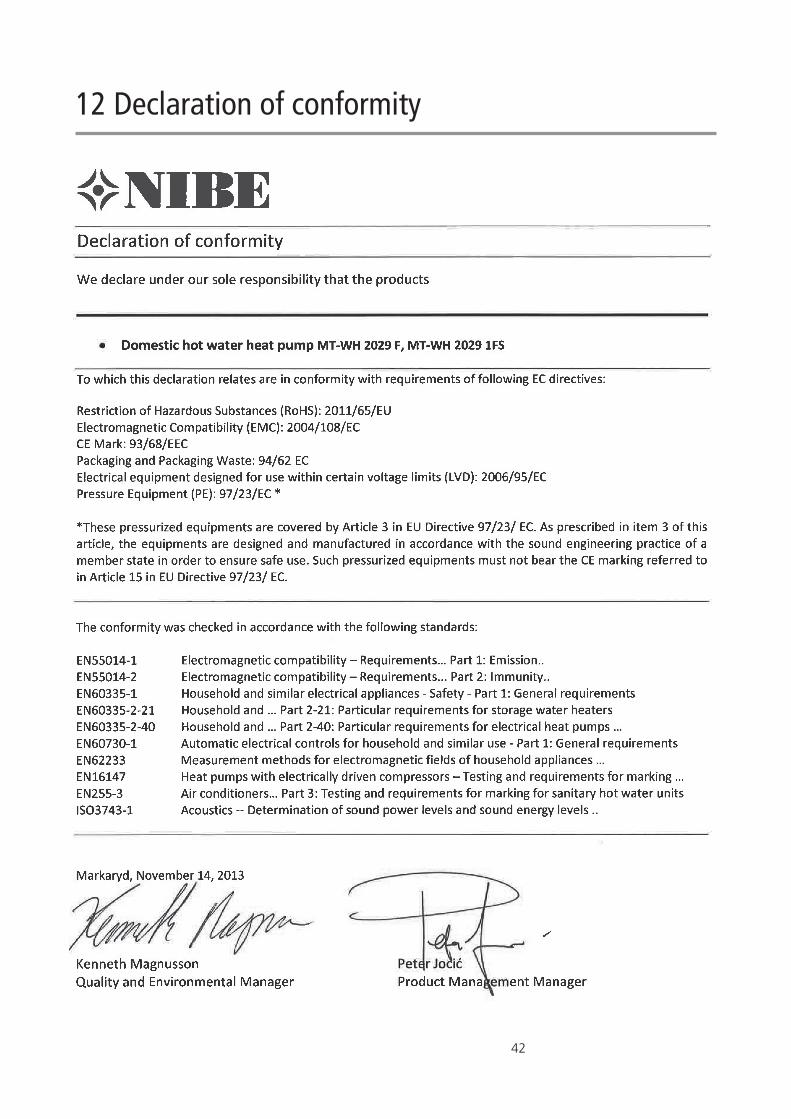
12 Declaration of conformity
43
13 Product and installer information
Installed model:
Serial number:
Accessories:
Installers
Pipe installation
Date:
Company:
Name:
Phone number:
Electrical installation
Date:
Company:
Name:
Phone number:
Commissioning
Date:
Company:
Name:
Phone number:

NIBE AB SwedenHannabadsvägen 5Box 14SE-285 21 [email protected] OE0
1-93
5-14
08 M
anua
l arti
cle n
o. 7
1425
5999


