Abstract Ever since the dawn of civilization, man has always been using mechanism and machines, which will support and help him to realize his dreams and desires, Energy convertors are one of its kind and have been man’s best friend to make his life better and easier. With the development of science and technology, new mechanism and devices were available to man to aid him in this task. Invention of turbines enabled him to develop a lot, which were later mechanized, and today we have a variety in it. With the development of turbines, man human kind was able to push to the limits of inventions and innovations.
This project summarizes the utilization of a kinetic energy going waste in our daily life which can be used to light up the darkness in many ways, new innovations being developed, and breaking the barriers to further development. In this light on a very simple kind of a traditional turbine i.e., a Pelton Wheel Turbine and how we make use of it to harness the energy running in the water pipes of our houses and convert it to usable form of electricity to use for lighting the house at night and load shedding. Thus making the environment greener by saving on Government supplied electricity. Key Words: Kinetic Energy, Turbine, Electricity, Load Shedding, Greener.
1. INTRODUCTION There are two types of turbines, reaction & impulse, the difference being the manner of head conversion. In reaction turbines the fluid fills the blade passages, and the head change or pressure drop occurs within the runner. An impulse turbine first converts the water head through a nozzle into a high-velocity jet, which then strikes the buckets at one position as they pass by. The runner passages are not fully filled, and the jet flow past the buckets is essentially at constant pressure. The Pelton turbine used in this project is an impulse turbine. The Pelton turbine consists of three basic components as shown in Figure. A stationary inlet nozzle, a runner and a casing. The runner consists of multiple buckets mounted on a rotating wheel. The jet strikes the buckets and imparts momentum.
Fig-1: Basic components of pelton wheel turbine
1.1 OBJECTIVE OF THE WORK
There are 3 main works that we have set for this project and are as follows.
1. Turbine and generator must adequately charge the battery whenever they run.
2. To check that turbine works at maximum efficiency always inside the enclosed chamber.
3. Handling and maintenance of the device should be very easy, handy & cheap.
1.2 TARGET SPECIFICATIONS As we observe that the energy generated from this setup is sufficient enough to light a room for about 6 to 7 hours which is great importance during power cut offs, this will serve the purpose of human comfort to some extent. This will help to save energy and the saved energy can be utilized by the people of rural areas for agricultural purpose and development of nation is possible.
1.3 LITERATURE SURVEY We have studied in fluid mechanics that if at the inlet of the turbine, the energy available is only kinetic energy, the turbine is known as impulse turbine. As the water flows over the vanes, the pressure is atmospheric from inlet to outlet of the turbine. The construction and installation of this turbine is much simpler and economic process and it also provides maximum power at the output and hence this setup includes a pelton wheel blades or turbine. The pelton wheel is a tangential flow impulse turbine. The water strikes the bucket along the tangent of the runner. The energy available at the inlet of the turbine is used for high heads and is named after L.A.Pelton, an American Engineer.
1.4 BRIEF BACKGROUND THEORY As it can be seen from the picture above that is the rain water is collected and forced onto a pelton wheel and the power is extracted. This generated power is saved in a battery of desired capacity and used whenever needed. This basic knowledge is used for our project and limitations of being used only during rainy seasons are eliminated and can be used for whole year without being dependent on natural resources such as rain.
1.5 PRESENT STATE / RECENT DEVELOPMENTS IN THE WORK AREA As seen from the previous invention of portable green unit how the rain water is made use for the generation of power and extracting the benefits from it, there the roof water was
International Research Journal of Engineering and Technology (IRJET) e-ISSN: 2395 -0056
Volume: 04 Issue: 03 | Mar -2017 www.irjet.net p-ISSN: 2395-0072
collected and forced on to a pelton wheel for power generation. Here the concept is similar but the position of power house is changed and the utility of the resources is also enhanced. In this setup we fit an pelton wheel setup onto an over headed tank and when the water gushes through the inlet pipe the blades rotate and the energy gets generated, this concept is new and even has been proposed for patenting.
Fig -2: Pelton wheel applied in rain water harvesting
From the above method we adapted our project idea this is the base for our project, on the above method roof water is collected from the tilted roof and allowed to flow from the gutter pipes and made to flow over a pelton wheel which converts the kinetic energy of the freely flowing water to mechanical energy this mechanical energy is converted to electrical energy with the help of alternators connected in series for maximum output, and is parallel for minimum output. This setup produces power only when there is rain fall i.e. this is a dependent on natural resources and hence has its limitations. Another setup was created to increase the efficiency of the setup by providing an additional tank to increase the head of the out flowing water. The figure below shows the setup for the same
1.6 THEORETICAL DISCUSSIONS
The concept of placing the power house may be different but the working principle and final destination is the same. The power generated may vary but the application is same and very useful. Our product it is very helpful to society as it helps in saving some amount of energy and stores it in some of the storage devices, which can be utilized to light a house during power cuts. This setup is useful throughout the year
for producing needful energy.
1.7 GENERAL ANALYSIS
Portable green unit generates power which is not uniform it varies a lot depending upon the water flow from the roof and the quantity of rain which is not stable and hence the power developed is varying in nature a separate device for drawing out synchronous current/ power is fitted which further adds to the cost of the setup. In Domestic power-pack a stable
head is produced using a external pump or a motor and hence the power developed is synchronous and uniform in nature and no additional device is fitted to draw same
current and hence this setup is preferred to the later.
2. METHODOLOGY
The method adapted for fabrication and testing of this power-pack should be simple and cheaper enough so that maximum number of customers are attracted towards this product and purchase this product and they themselves can take care of it or can build a new component of it. So we have taken a similar method for manufacturing this product. This technique is simpler and cheaper for any of the firm to manufacture. If manufactured in mass the cost will further decrease.
Fig-3: layout of project
Fig-4: Block diagram of domestic power pack setup
International Research Journal of Engineering and Technology (IRJET) e-ISSN: 2395 -0056
Volume: 04 Issue: 03 | Mar -2017 www.irjet.net p-ISSN: 2395-0072
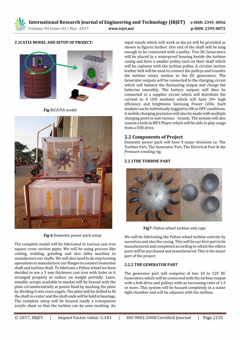
The complete model will be fabricated in various cast iron square cross section pipes. We will be using process like cutting, welding, grinding and also lathe machine to manufacture our shafts. We will also need to do step turning operations to manufacture our flanges to connect Generator shaft and turbine shaft. To fabricate a Pelton wheel we have decided to use a 5 mm thickness cast iron with holes in it arranged properly to reduce on weight partially. Later, metallic scoops available in market will be brazed with the plate circumferentially at points fixed by marking the plate by dividing it into even angels. The plate will be drilled to fit the shaft in center and the shaft ends will be held in bearings. The complete setup will be housed inside a transparent acrylic sheet so that the turbine can be seen working. An
input nozzle which will work as the jet will be provided as shown in figures further. One end of the shaft will be long enough to be connected with a pulley. Two DC Generators will be placed in a waterproof housing beside the turbine casing and have a smaller pulley each on their shaft which will be coplanar with the turbine pulley. A circular section leather belt will be used to connect the pulleys and transfer the turbine rotary motion to the DC generators. The Generator outputs will be connected to the charging circuit which will balance the fluctuating output and charge the batteries smoothly. The battery outputs will then be connected to a supplier circuit which will distribute the current to 4 LED modules which will have 20+ high efficiency and brightness Samsung Power LEDs. Each module can be individually toggled to ON or OFF conditions. A mobile charging provision will also be made with multiple charging ports to suit various brands. The system will also consist a built in MP3 Player which will be able to play songs from a USB drive.
2.2 Components of Project Domestic power pack will have 4 major divisions i.e. The Turbine Part, The Generator Part, The Electrical Part & the Pressure creating rig; ` 2.2.1THE TURBINE PART
Fig7: Pelton wheel turbine and cups
We will be fabricating the Pelton wheel turbine entirely by ourselves and also the casing. This will be our first part to be manufactured and completed according to which the others parts will be purchased and manufactured. This is the major part of the project
2.2.2 THE GENERATOR PART
The generator part will comprise of two 10 to 12V DC Generators which will be connected with the turbine output with a belt drive and pulleys with an increasing ratio of 1:3 or more. This system will be housed completely in a water tight chamber and will be adjacent with the turbine.
International Research Journal of Engineering and Technology (IRJET) e-ISSN: 2395 -0056
Volume: 04 Issue: 03 | Mar -2017 www.irjet.net p-ISSN: 2395-0072
A controller circuit will be built which will receive the currents from the generators and charge the 12V 5amps battery bank which is capable of powering the LED modules as discussed before. A LED display will be mounted to display the voltage being generated and the battery status.
2.2.4 THE PRESSURE CREATING RIG
To demonstrate the capacity of the device we have induced, we need a testing to show it. So we will be building a recyclable water head where we will be using a standard 0.5 HP water pump to create the pressure which will be let into the turbine to generate electricity. This will be the exact pump used to fill the overhead tanks in the today’s houses
2.3 ASSUMPTIONS MADE The following assumptions are made for setup
The flow is ideal i.e., viscosity is zero The flow is steady The flow is incompressible The flow is irrational
2.4 COMPONENT SPECIFICATIONS Components used in this setup are:
Pump:-0.5HP capacity head of 20m, 2800rpm.
Pipes of diameter 20mm and 12.5mm Water tank of 200ltrs capacity Stand or frame for mounting tank and our setup of material caste iron
Pelton wheel cups of material cast iron of diameter 50mm Plate on which cups are attached made of cast iron of diameter 300mm thickness 5mm
Shaft of diameter 20mm length 200mm made up of cast iron
2 Gear sets of plastic having gear ratio of 1.38 Johnson geared alternators of capacity of running 1000rpm and generation capacity 20-24V
Battery setup of capacity 12V, 7.5A
Control circuit consisting of ADC, Microcontroller, Digital display, zener diode, and resistors
CFL lamps of capacity, 1Watts, 72 in number
Acrylic sheet chamber for the power-pack
2.5 Experimental calculations
This part consists of the design parameters which are considered for designing the blades and other parameters for domestic power-pack. Which are as follows
Design of shaft:
We have from design data hand book:-
do= [(16/ςm π) x (M+√M2+T2)]1/3
T= Torque = Fxq = (2x9.81) N x 150/1000m =2.943N-m
M=Moment=0.5xFxd =0.5x19.62x0.150=1.4715Nm
Max stress= ςm= (F/A) ± (M/Z) where A=9.42x10⁻⁵m2, Z=7.85x10⁻⁷m4
ςm=2.985x10⁶N/m2 =2.9585MN/m2
Substituting the values in above equation for calculating and standardizing diameter we get, do=0.02091mm
do≈ 20mm (standardized from DHB)
Power generation:
P= (2πNT)/60000
P = (2πx930x2.943)/60000
P= 0.2866kW
Discharge:
Q= AxV
Q= (π/4)x(0.02)2x0.300x2
Q= 1.884x10⁻³m3/s
Angular velocity in rad/sec:
T=106P/ ῲ
ῲ=106P/T
ῲ=106x0.286/(2.943x60x10000
ῲ=1.623rad/sec
Specific Speed:
Ns= Nx√P/H5/4
Ns= 930x√0.2866/ (20)5/4
Ns=930x0.0126
Ns=11.759
Ks= Nx√P/(ρ1/2x(gH)5/4)
Ks=930x√0.2866/(10001/2x(9.81x20)5/4)
Ks=0.0214
International Research Journal of Engineering and Technology (IRJET) e-ISSN: 2395 -0056
Volume: 04 Issue: 03 | Mar -2017 www.irjet.net p-ISSN: 2395-0072
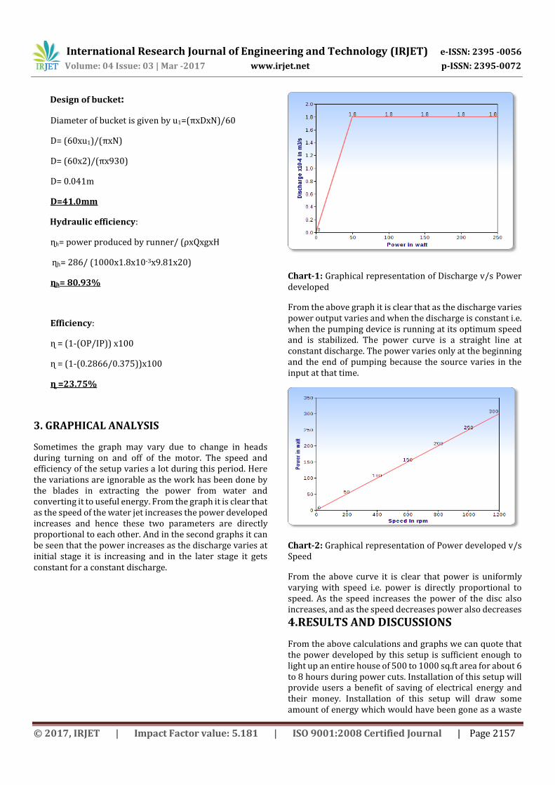
Sometimes the graph may vary due to change in heads during turning on and off of the motor. The speed and efficiency of the setup varies a lot during this period. Here the variations are ignorable as the work has been done by the blades in extracting the power from water and converting it to useful energy. From the graph it is clear that as the speed of the water jet increases the power developed increases and hence these two parameters are directly proportional to each other. And in the second graphs it can be seen that the power increases as the discharge varies at initial stage it is increasing and in the later stage it gets constant for a constant discharge.
Chart-1: Graphical representation of Discharge v/s Power developed
From the above graph it is clear that as the discharge varies power output varies and when the discharge is constant i.e. when the pumping device is running at its optimum speed and is stabilized. The power curve is a straight line at constant discharge. The power varies only at the beginning and the end of pumping because the source varies in the input at that time.
Chart-2: Graphical representation of Power developed v/s Speed
From the above curve it is clear that power is uniformly varying with speed i.e. power is directly proportional to speed. As the speed increases the power of the disc also increases, and as the speed decreases power also decreases
4.RESULTS AND DISCUSSIONS
From the above calculations and graphs we can quote that the power developed by this setup is sufficient enough to light up an entire house of 500 to 1000 sq.ft area for about 6 to 8 hours during power cuts. Installation of this setup will provide users a benefit of saving of electrical energy and their money. Installation of this setup will draw some amount of energy which would have been gone as a waste
International Research Journal of Engineering and Technology (IRJET) e-ISSN: 2395 -0056
Volume: 04 Issue: 03 | Mar -2017 www.irjet.net p-ISSN: 2395-0072
anyway this power pack will save some amount of energy same as an UPS system which uses the available energy saves from it and spends whenever required. In our setup also we save the energy developed from water flowing in tank and then utilise it during power cuts.
5. CONCLUSION AND FUTURE SCOPE 5.1CONCLUSION Our Aim is to Light up a small home of around 600-800 square feet area with a set of LED lights as follows.
1. 2V 1watt, High Glow Samsung LED light – 12 no’s on each plate – A total of 4 plates.
(72 LEDs total)
2. Samsung LED lights are known for their brightness, long life and efficiency; hence we decided to use it in our project.
3. The overall goal is to harness the kinetic energy and convert it to usable electric form and store in the battery.
And hence the desired goals are achieved and the project is in full swing by giving colorful results, and therefore this setup is of much importance during cut offs for human comforts. Practical and theoretical results are in match and have a great significance on the energy being harnessed by this setup, commercialization of this product would definitely add to the saving of energy resources for developing power, which can be utilized by the people in rural area for the development of their livelihood and the betterment of the society and nation.
5.2Future scope
In future our young engineers can work on improving the efficiency of this setup by providing
Nozzle effect Splitting the cups into halves Providing vanes at the drain end Developing generators which can be used for
generation of sufficient power which is used for running high load devices
ACKNOWLEDGEMENT I acknowledge with a deep sense of gratitude towards the encouragement and scholarly guidance received from my project guide Prof. G.B.Deshpande (S.G.Balekundri institute of Technology Belagavi, Karnataka, India) . I would also like to thank Principal Dr.S.S.Salimath(S.G.Balekundri institute of technology) for his motivation and also to all my teachers, friends who directly & indirectly supported, guided & helped me in possible ways. REFERENCES
[1]. Fifth international synopsis on Energy (portable green unit), Puerto-rico energy centre-laccei February, 7-8, 2013, Puerto-rico
[2]A Text book on Fluid Mechanics and Machinery by
S.K.Agarwal [3] A Text book of Turbo Machines - M.S.Govindgouda & A.M.NAGARAJ [4]Fluid Machinery” by B.K. Venkanna.
[5]Theory of Machines by Dr. R.S.Khurmi. [6]Text Book of Machine Design, by Dr. R.S.Khurmi.
Sharabanna is Working as an Assistant Professor Department of Mechanical Engineering in SDMT Polytechnic College Sindhanur, Karnataka, India. .He has done his B.E in Mechanical Engineering and M.Tech in Thermal Power Engineering. He has Published Two International Journal Papers, his Area of Interest in Heat Transfer and Power Generation.