Domino ® XL DF 700 Tenon Joiner Tenon Joiner Supplemental User’s Manual WARNING To reduce the risk of serious injury, read and understand all safety precautions and instructions in this manual before using this tool.
Transcript
Domino® XL DF 700Tenon Joiner
Tenon Joiner Supplemental User’s Manual
WARNING To reduce the risk of serious injury, read and understand all safety precautions and instructions in this manual before using this tool.
2 Domino XL DF700
Limited Warranty
30 Day Money Back Guarantee We are so confident that you will thoroughly enjoy our tools, that we offer a 30 day money back guarantee. If you are not
completely satisfied, your full purchase price will be refunded, excluding all freight charges.
1+2 Limited Warranty Festool USA offers a 3-year limited warranty, one of the longest in the industry. This warranty is valid on the pre-condition that the tool is used and operated in compliance with the Festool
operating instructions. Festool USA warrants that the specified tool will be free from defects in materials and workmanship for a term of 3 years from the date of purchase.
Conditions of 1+2 Limited Warranty You are entitled to a free extended limited warranty (1 year + 2 years = 3 Years) for your Festool power tool. Festool USA is responsible for all shipping costs during the first year of the warranty. During the second and third year of the warranty, the customer is responsible for shipping the tool to Festool. Festool will pay for return shipping to the customer using UPS Ground Service. All warranty service is valid 3 years from the date of purchase on your receipt or invoice.
Excluded from the coverage under this warranty are: normal wear and tear, damages caused by misuse, abuse, or neglect; damage caused by anything other than defects in material and workmanship. This warranty does not apply to accessory items such as circular saw blades, drill bits, router bits, jigsaw blades, sanding belts, and grinding wheels. Also excluded are “wearing parts,” such as carbon brushes, lamellas of air tools, rubber collars and seals, sanding discs and pads, batteries, and Festool gear (hats and t shirts).
The obligations of Festool USA in its sole discretion under this warranty shall be limited to repair or replacement or a refund of the purchase price for any Festool portable power tool that is found to have a defect in materials or workmanship during
the warranty period. FESTOOL USA SHALL NOT BE LIABLE FOR ANY CONSEQUENTIAL, INCIDENTAL OR SPECIAL DAMAGES REGARDLESS OF THE THEORY OF LAW ON WHICH THE CLAIM IS BASED. ALL WARRANTIES IMPLIED BY STATE LAW, INCLUDING THE IMPLIED WARRANTIES OR MERCHANTABILITY AND FITNESS FOR A PARTICULAR PURPOSE ARE HEREBY LIMITED TO THE DURATION OF THREE YEARS.
Some states in the U.S. and some Canadian provinces do not allow the limitations on how long an implied warranty lasts, so the above limitation may not apply to you. This warranty gives you specific legal rights, and you may also have other rights that vary from state to state in the U.S. and from province to province in Canada.
With the exception of any warranties implied by state or prov-ince law as limited above, the foregoing express limited war-ranty is exclusive and in lieu of all other warranties, guarantees, agreements, and similar obligations of Festool USA. Festool USA makes no other warranty, express or implied, for Festool por-table power tools. No agent, representative, distributor, dealer, or employee of Festool USA has the authority to increase or otherwise change the obligations or limitations of this warranty.
Repairs If your Festool power tools require repair, you must contact our Service Department at (800) 554-8741 for authorization and address details. No collect shipments will be accepted. No Festool hats, t-shirts or other wearables may be returned.
Also contact our Service Department at the telephone number listed above if you have any questions about warranty claim procedures.
Returns If you need to return your Festool tools for any reason, please return it to the dealer from which you originally bought the tool.
Liability StatementThis product has been built to the high standards of Festool. Please do not attempt to operate or repair this equipment without adequate training. Any use, operation, or repair in con-travention of this document is at your own risk. By acceptance of this system you hereby assume all liability consequent to
your use or misuse of this equipment. Festool USA assumes no liability for incidental, special, or consequential damage of any kind. Equipment specifications, applications, and options are subject to change at the sole discretion of Festool USA without notice.
Proprietary NoticeAll drawings and information herein are the property of Festool, TTS Tooltechnic Systems AG & Co. KG. All unauthorized use and reproduction is prohibited.
It is important for you to read and understand this manual. The information it contains relates to protecting YOUR SAFETY and PREVENTING PROBLEMS. The symbols below are used to help you recognize this information.
WARNING! Indicates a potentially hazardous situation which, if not avoided, could result in death or serious injury.
CAUTION! Indicates a potentially hazardous situation which, if not avoided, could result in minor or moderate injury.
NOTICE: Indicates a potential situation which, if not avoided, can result in property damage or damage to the tool.
Note: Indicates information, notes, or tips for improving your success using the tool.
ContentsAbout This Manual ........................................... 3
Tool Symbols ...................................................3General Power Tool Safety Warnings .............. 4
Work Area Safety ..........................................4Electrical Safety ............................................4Personal Safety .............................................4Power Tool Use and Care ................................4Service ........................................................5
Specific Safety Rules for Tenon Joiners ................5Respiratory Exposure Safety Warnings ................5
Setup ............................................................... 7Setting Up a New Domino Joiner ........................ 7Setting the Fence Angle .................................... 7Setting the Fence Height ...................................8Setting the Mortise Width ..................................8Setting the Mortise Depth ................................. 9Changing the Mortising Bit ................................ 9
Operation ...................................................... 10Overview, General Notes, and Tips ................... 10
Choosing the Right Domino Tenon Size ........... 10
Domino Tenon Placement Guidelines .............. 10Plug-It® Power Cord ...................................... 10Using Dust Extraction ..................................... 11Using the Stop Pins ........................................ 11Using the Base Support Bracket ....................... 11Using the Optional Cross Stops ........................ 12Using the Vertical Alignment Marks ................... 12Using the Optional Trim Stop ........................... 13Using the Optional Hand Rail Fence .................. 13
WARNING! Read all safety warnings and instructions. Failure to follow the warnings and instructions may result in electric shock, fire, and/or serious injury.
Save all warnings and instructions for future reference.
Work Area Safety ► Keep your work area clean and well lit. Cluttered or dark work areas invite accidents.
► Do not operate power tools in explosive atmospheres, such as in the presence of flammable liquids, gases, or dust. Power
tools create sparks which may ignite the dust or fumes.
► Keep children and bystanders away while operating a power tool. Distractions can cause you to lose control.
Electrical Safety ► Power tool plugs must match the outlet. Never modify the plug in any way. Do not use any adapter plugs with earthed (grounded) power tools. Unmodified plugs and matching outlets will reduce risk of electric shock.
► Avoid body contact with earthed or grounded surfaces such as pipes, radiators, ranges and refrigerators. There is an increased risk of electric shock if your body is earthed or grounded.
► Do not expose power tools to rain or wet conditions. Water entering a power tool will increase the risk of electric shock.
► Do not abuse the cord. Never use the cord for carrying, pull-ing, or unplugging the power tool. Keep cord away from heat, oil, sharp edges or moving parts. Damaged or entangled cords increase the risk of electric shock.
► When operating a power tool outdoors, use an extension cord suitable for outdoor use. Use of a cord for outdoor use reduces the risk of electric shock.
► If operating a power tool in a damp location is unavoidable, use a ground fault circuit interrupter (GFCI) protected supply. Use of a GFCI reduces the risk of electric shock.
► Never use an extension cord that is damaged, including cuts, exposed wires, or bent/missing prongs. Damaged extension cords increase the risk of fire or electric shock.
► Use only extension cords rated for the purpose.
► Use only extension cords rated for the amperage of this tool and the length of the cord. Using too small of an extension cord can cause the cord to overheat.
Extension Cord RatingsCord Length Size (AWG)<50 Ft. 1450-100 Ft. 12>100 Ft. Not recommended
Personal Safety ► Stay alert, watch what you are doing, and use common sense when operating a power tool. Do not use a power tool while tired or under the influence of drugs, alcohol, or medication. A moment of inattention while operating power tools may result in serious personal injury.
► Use personal protective equipment. Always wear eye pro-tection. Protective equipment such as dust mask, non-skid safety shoes, hard hat, or hearing protection used for appro-priate conditions will reduce personal injuries.
► Prevent unintentional starting. Ensure the switch is in the off-position before connecting to power source, picking up, or carrying the tool. Carrying power tools with your finger on the switch or energizing power tools that have the switch on invites accidents.
► Remove adjusting key or wrench before turning the power
tool on. A wrench or a key that is left attached to a rotating part of the tool may result in personal injury.
► Do not overreach. Keep proper footing and balance at all times. This enables better control of the tool in unexpected situations.
► Dress properly. Do not wear loose clothing or jewelry. Keep your hair, clothing, and gloves away from moving parts. Loose clothes, jewelry, or long hair can be caught in moving parts.
► If devices are provided for the connection of dust extrac-tion and collection facilities, ensure these are connected and properly used. Use of dust collection can reduce dust-related hazards.
► Always wear safety glasses complying with ANSI Z87.1. Ordinary glasses are not proper protection.
Power Tool Use and Care ► Do not force the power tool. Use the correct power tool for your application. The correct power tool will do the job better and safer at the rate for which it is designed.
► Do not use the power tool if the switch does not turn it on and off. Any power tool that cannot be controlled with the switch is dangerous and must be repaired.
► Disconnect the plug from the power source before making any adjustments, changing accessories, or storing the tool. Such preventive safety measures reduce the risk of starting
the tool accidentally.
► Store idle tools out of reach of children and do not allow persons unfamiliar with the power tool or these instructions to operate the power tool. Power tools are dangerous in the hands of untrained users.
► Maintain power tools. Check for misalignment or binding of moving parts, breakage of parts and any other condition that may affect the power tool’s operation. If damaged, have the power tool repaired before use. Many accidents are caused by
Supplemental Owner’s Manual 5
poorly maintained power tools.
► Keep cutting tools sharp and clean. Properly maintained tools with sharp cutting edges are less likely to bind and are easier to control.
► Use the power tool, accessories, and tool bits etc. in accor-
dance with these instructions, taking into account the working conditions and the work to be performed. Use of the power tool for operations different from those intended could result in a hazardous situation.
► To reduce the risk of serious injury, never alter or misuse the power tool.
Service ► Have your power tool serviced by a qualified repair person using only identical replacement parts. This will ensure that
the safety of the power tool is maintained.
Specific Safety Rules for Tenon Joiners ► Mortising bits must be rated for at least the speed recom-mended on the tool. Mortising bits running over rated speed can fly apart and cause injury.
► Always use the fence. The fence protects the operator from unintentional contact with the mortising bit. When the fence is removed from the joiner, the spinning and oscillating cutter is exposed and can cause serious injury.
► Keep hands away from the cutting area. Never place your hand on the front face of the fence while the tool is running.
► Use only Festool authorized mortising bits. Non-approved mortising bits can come loose during operation.
► Never use dull or damaged mortising bits. Dull or damaged
mortising bits can cause the tool to lurch sideways unexpect-edly and lead to a loss of control of the power tool.
► Do not operate the tool if the spring-loaded fence does not return to its forward rest position. The fence covers the mor-tising bit and prevents accidental contact. If the slides of the fence do not move freely, have the tool serviced immediately.
► Wait for the cutter to stop before setting the tool down. An exposed cutter may engage the surface leading to possible loss of control and serious injury.
► Use clamps or other practical way to secure and support the workpiece to a stable platform. Holding the work by hand or against your body is unstable and may lead to loss of control.
Respiratory Exposure Safety Warnings ► Substantial or repeated inhalation of dust and other airborne contaminants, in particular those with a smaller particle size, may cause respiratory or other illnesses. Various dusts created by power sanding, sawing, grinding, drilling and other construction activities contain chemicals or substances known (to the State of California and others) to cause cancer, birth defects or other reproductive harm. Some examples of these chemicals/substances are:
► lead from lead-based paints;
► crystalline silica from bricks, cement, and other masonry products;
► arsenic and chromium from chemically-treated lumber; and
► some wood dusts, especially from hardwoods, but also from some softwoods such as Western Red Cedar.
► The risk from these exposures varies, depending on how often you do this type of work. To reduce your exposure to these chemicals: work in a well ventilated area and use a properly functioning dust extraction system. When the inhala-tion of dust cannot be substantially controlled, i.e., kept at or near the ambient (background) level, the operator and any bystanders should wear a respirator approved by NIOSH for the type of dust encountered.
Tool Description
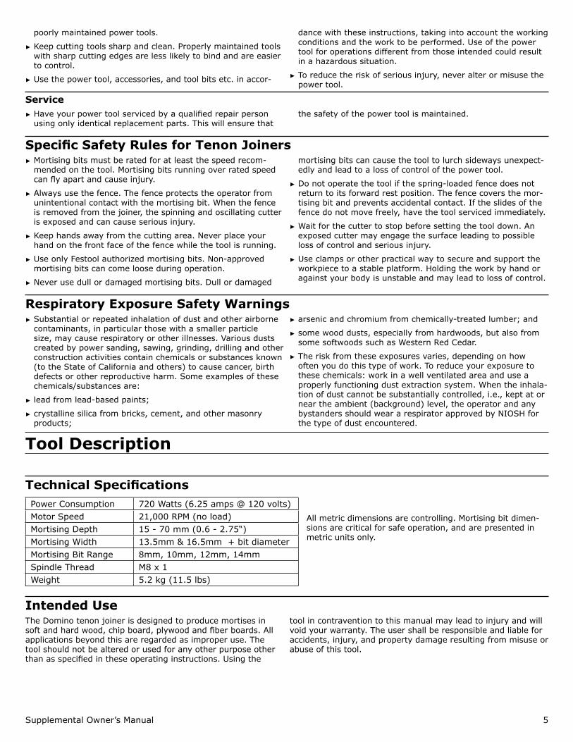
Technical SpecificationsPower Consumption 720 Watts (6.25 amps @ 120 volts)Motor Speed 21,000 RPM (no load)Mortising Depth 15 - 70 mm (0.6 - 2.75“)Mortising Width 13.5mm & 16.5mm + bit diameterMortising Bit Range 8mm, 10mm, 12mm, 14mmSpindle Thread M8 x 1Weight 5.2 kg (11.5 lbs)
All metric dimensions are controlling. Mortising bit dimen-sions are critical for safe operation, and are presented in metric units only.
Intended UseThe Domino tenon joiner is designed to produce mortises in soft and hard wood, chip board, plywood and fiber boards. All applications beyond this are regarded as improper use. The tool should not be altered or used for any other purpose other than as specified in these operating instructions. Using the
tool in contravention to this manual may lead to injury and will void your warranty. The user shall be responsible and liable for accidents, injury, and property damage resulting from misuse or abuse of this tool.
6 Domino XL DF700
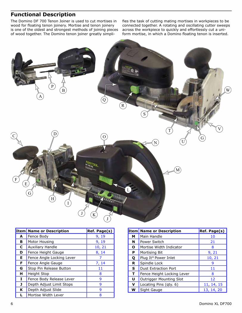
Functional DescriptionThe Domino DF 700 Tenon Joiner is used to cut mortises in wood for floating tenon joinery. Mortise and tenon joinery is one of the oldest and strongest methods of joining pieces of wood together. The Domino tenon joiner greatly simpli-
fies the task of cutting mating mortises in workpieces to be connected together. A rotating and oscillating cutter sweeps across the workpiece to quickly and effortlessly cut a uni-form mortise, in which a Domino floating tenon is inserted.
R
T V
W
G
S
U
Q
J
F
HG
E
I
NC
L
D
M
JK
P
O
AB
Item Name or Description Ref. Page(s)A Fence Body 9, 19B Motor Housing 9, 19C Auxiliary Handle 10, 21D Fence Height Gauge 8, 14E Fence Angle Locking Lever 7F Fence Angle Gauge 7, 14G Stop Pin Release Button 11H Height Stop 8I Fence Body Release Lever 9J Depth Adjust Limit Stops 9K Depth Adjust Slide 9L Mortise Width Lever 8
Item Name or Description Ref. Page(s)M Main Handle 10N Power Switch 21O Mortise Width Indicator 8P Mortising Bit 9, 21Q Plug It® Power Inlet 10, 21R Spindle Lock 9S Dust Extraction Port 11T Fence Height Locking Lever 8U Outrigger Mounting Slot 12V Locating Pins (qty. 6) 11, 14, 15W Sight Gauge 13, 14, 20
Supplemental Owner’s Manual 7
Setup
Setting Up a New Domino JoinerCongratulations on your purchase of a new Festool Domino Tenon Joiner. The Domino joiner is the finest portable loose tenon joiner in the world. Before using your new Domino joiner, make sure you fully read and understand all of the precautions and safety information presented in this manual.
WARNING! To reduce the risk of injury from contact with a moving part, always unplug the joiner before making any inspections or adjustments, or before installing or removing any accessory!
1. With the joiner unplugged, inspect the mortising bit. Make sure it is not bent, chipped, or otherwise damaged, and make sure the bit is fully tightened on the spindle. (Refer to “Changing the Mortising Bit” on page 9 for more information).
CAUTION! Check regularly whether the mortising bit is in good condition. Mortising bits that are bent or damaged can break, and should no longer be used.
2. Peel off the protective film from the bottom of the joiner baseplate.
3. Set up the joiner for the appropriate type of operation as described throughout the remainder of this section.
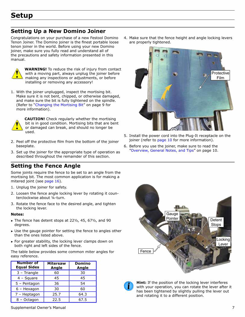
4. Make sure that the fence height and angle locking levers are properly tightened.
Protective Film
5. Install the power cord into the Plug-It receptacle on the joiner (refer to page 10 for more information).
6. Before you use the joiner, make sure to read the ”Overview, General Notes, and Tips” on page 10.
Setting the Fence AngleSome joints require the fence to be set to an angle from the mortising bit. The most common application is for making a mitered joint (see page 16).
1. Unplug the joiner for safety.
2. Loosen the fence angle locking lever by rotating it coun-terclockwise about ¼-turn.
3. Rotate the fence face to the desired angle, and tighten the locking lever.
Notes: ► The fence has detent stops at 22½, 45, 67½, and 90 degrees.
► Use the gauge pointer for setting the fence to angles other than the ones listed above.
► For greater stability, the locking lever clamps down on both right and left sides of the fence.
The table below provides some common miter angles for easy reference.
Hint: If the position of the locking lever interferes with your operation, you can rotate the lever after it has been tightened by slightly pulling the lever out and rotating it to a different position.
ew Text
8 Domino XL DF700
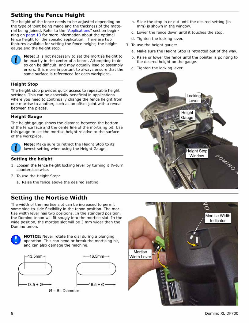
Setting the Fence HeightThe height of the fence needs to be adjusted depending on the type of joint being made and the thickness of the mate-rial being joined. Refer to the ”Applications” section begin-ning on page 13 for more information about the optimal fence height for the specific application. There are two features available for setting the fence height; the height gauge and the height stop.
Note: It is not necessary to set the mortise height to be exactly in the center of a board. Attempting to do so can be difficult, and may actually lead to assembly errors. It is more important to always ensure that the same surface is referenced for each workpiece.
Height StopThe height stop provides quick access to repeatable height settings. This can be especially beneficial in applications where you need to continually change the fence height from one mortise to another, such as an offset joint with a reveal between the pieces.
Height GaugeThe height gauge shows the distance between the bottom of the fence face and the centerline of the mortising bit. Use this gauge to set the mortise height relative to the surface of the workpiece.
Note: Make sure to retract the Height Stop to its lowest setting when using the Height Gauge.
Setting the height1. Loosen the fence height locking lever by turning it ¼-turn
counterclockwise.
2. To use the Height Stop:
a. Raise the fence above the desired setting.
b. Slide the stop in or out until the desired setting (in mm) is shown in the window.
c. Lower the fence down until it touches the stop.
d. Tighten the locking lever.
3. To use the height gauge:
a. Make sure the Height Stop is retracted out of the way.
b. Raise or lower the fence until the pointer is pointing to the desired height on the gauge.
c. Tighten the locking lever.
Locking Lever
Height Gauge
Height Stop Window
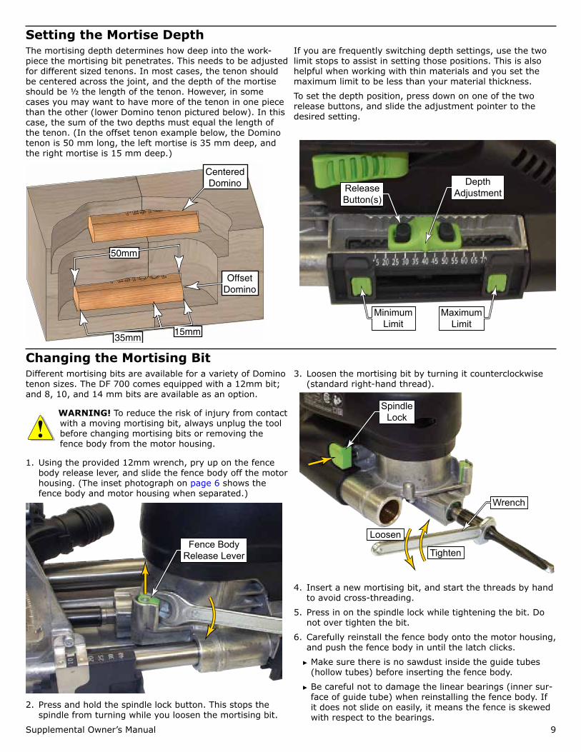
Setting the Mortise WidthThe width of the mortise slot can be increased to permit some side-to-side flexibility in the tenon position. The mor-tise width lever has two positions. In the standard position, the Domino tenon will fit snugly into the mortise slot. In the wide position, the mortise slot will be 3 mm wider than the Domino tenon.
NOTICE: Never rotate the dial during a plunging operation. This can bend or break the mortising bit, and can also damage the machine.
16.5mm13.5mm
16.5 + Ø13.5 + ØØ = Bit Diameter
Mortise Width Lever
Mortise Width Indicator
Supplemental Owner’s Manual 9
Setting the Mortise DepthThe mortising depth determines how deep into the work-piece the mortising bit penetrates. This needs to be adjusted for different sized tenons. In most cases, the tenon should be centered across the joint, and the depth of the mortise should be ½ the length of the tenon. However, in some cases you may want to have more of the tenon in one piece than the other (lower Domino tenon pictured below). In this case, the sum of the two depths must equal the length of the tenon. (In the offset tenon example below, the Domino tenon is 50 mm long, the left mortise is 35 mm deep, and the right mortise is 15 mm deep.)
Offset Domino
Centered Domino
15mm35mm
50mm
If you are frequently switching depth settings, use the two limit stops to assist in setting those positions. This is also helpful when working with thin materials and you set the maximum limit to be less than your material thickness.
To set the depth position, press down on one of the two release buttons, and slide the adjustment pointer to the desired setting.
Depth Adjustment
Minimum Limit
Release Button(s)
Maximum Limit
Changing the Mortising BitDifferent mortising bits are available for a variety of Domino tenon sizes. The DF 700 comes equipped with a 12mm bit; and 8, 10, and 14 mm bits are available as an option.
WARNING! To reduce the risk of injury from contact with a moving mortising bit, always unplug the tool before changing mortising bits or removing the fence body from the motor housing.
1. Using the provided 12mm wrench, pry up on the fence body release lever, and slide the fence body off the motor housing. (The inset photograph on page 6 shows the fence body and motor housing when separated.)
Fence Body Release Lever
2. Press and hold the spindle lock button. This stops the spindle from turning while you loosen the mortising bit.
3. Loosen the mortising bit by turning it counterclockwise (standard right-hand thread).
Spindle Lock
Wrench
Tighten
Loosen
4. Insert a new mortising bit, and start the threads by hand to avoid cross-threading.
5. Press in on the spindle lock while tightening the bit. Do not over tighten the bit.
6. Carefully reinstall the fence body onto the motor housing, and push the fence body in until the latch clicks.
► Make sure there is no sawdust inside the guide tubes (hollow tubes) before inserting the fence body.
► Be careful not to damage the linear bearings (inner sur-face of guide tube) when reinstalling the fence body. If it does not slide on easily, it means the fence is skewed with respect to the bearings.
10 Domino XL DF700
OperationOverview, General Notes, and TipsBecause the look and feel of the Domino joiner may already be familiar to you, or similar to other tools you may have used in the past, you might be tempted to forego a basic introduction to using the tool. However, unlike other tools of similar look and feel, the Domino machine is extremely precise in its operation. For this reason, it is recommended that you spend some time practicing using the Domino joiner before you begin using it for your fine woodworking projects.
For best results, observe the following tips:
► Always secure the workpiece firmly.
► Hold the Domino Joiner firmly by the front handle and loosely by the rear handle. This keeps control of the joiner at the front without biasing the main body skewed from the fence.
► Plunge the mortising bit into the workpiece with a slow and steady pace.
Choosing the Right Domino Tenon SizeBecause the Domino system is a form of the classic mortise and tenon joinery, it should follow much of the same guide-lines of mortise and tenon joinery. Here are some guidelines to assist you in making your choices:
► When the strength of your workpieces is comparable to the strength of the Domino tenon (e.g. general hard woods) then the thickness of the Domino tenon should be
approximately 1/3 the thickness of the workpieces.
► For softer woods, such as pine, the joint will be stronger when the tenon is 1/3 or slightly less.
► For plywoods, especially low-grade construction plywoods, the Domino tenon is much stronger than the surrounding wood, so it is best to maximize the strength of the sub-strate by minimizing the thickness of the tenon.
Domino Tenon Placement GuidelinesThere are no steadfast rules on where tenons should be placed, especially when they are used for alignment pur-poses. For edge joining boards, a typical placement might be 6 to 8 inches apart.
However, when tenons are used to strengthen a joint, you might be tempted to place the tenons too close together. This can actually weaken the joint by removing too much of the substrate material.
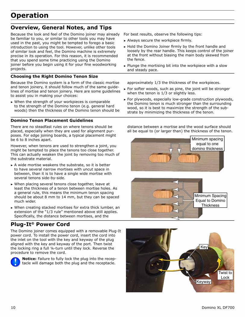
► A wide mortise weakens the substrate, so it is better to have several narrow mortises with uncut space in between, than it is to have a single wide mortise with several tenons side-by-side.
► When placing several tenons close together, leave at least the thickness of a tenon between mortise holes. As a general rule, this means the minimum tenon spacing should be about 8 mm to 14 mm, but they can be spaced much wider.
► When creating stacked mortises for extra thick lumber, an extension of the “1/3 rule” mentioned above still applies. Specifically, the distance between mortises, and the
distance between a mortise and the wood surface should all be equal to (or larger than) the thickness of the tenon.
Minimum spacing equal to one
domino thickness
Minimum Spacing Equal to Domino
Thickness
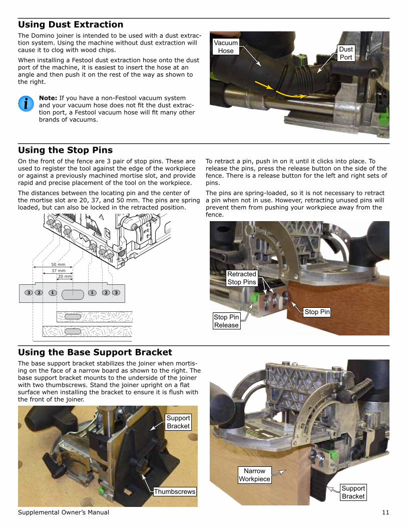
Plug-It® Power Cord The Domino joiner comes equipped with a removable Plug-It power cord. To install the power cord, insert the cord into the inlet on the tool with the key and keyway of the plug aligned with the key and keyway of the port. Then twist the locking ring a full ¼-turn until they lock. Reverse the procedure to remove the cord.
Notice: Failure to fully lock the plug into the recep-tacle will damage both the plug and the receptacle.
Key
Keyway
Twist to Lock
Supplemental Owner’s Manual 11
Using Dust ExtractionThe Domino joiner is intended to be used with a dust extrac-tion system. Using the machine without dust extraction will cause it to clog with wood chips.
When installing a Festool dust extraction hose onto the dust port of the machine, it is easiest to insert the hose at an angle and then push it on the rest of the way as shown to the right.
Note: If you have a non-Festool vacuum system and your vacuum hose does not fit the dust extrac-tion port, a Festool vacuum hose will fit many other brands of vacuums.
Dust Port
Vacuum Hose
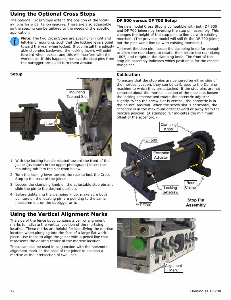
Using the Stop PinsOn the front of the fence are 3 pair of stop pins. These are used to register the tool against the edge of the workpiece or against a previously machined mortise slot, and provide rapid and precise placement of the tool on the workpiece.
The distances between the locating pin and the center of the mortise slot are 20, 37, and 50 mm. The pins are spring loaded, but can also be locked in the retracted position.
20 mm37 mm50 mm
123 1 2 3
To retract a pin, push in on it until it clicks into place. To release the pins, press the release button on the side of the fence. There is a release button for the left and right sets of pins.
The pins are spring-loaded, so it is not necessary to retract a pin when not in use. However, retracting unused pins will prevent them from pushing your workpiece away from the fence.
Stop Pin
Retracted Stop Pins
Stop Pin Release
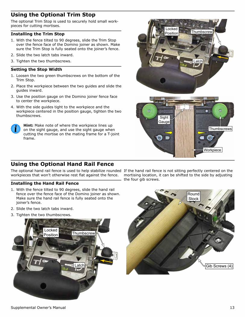
Using the Base Support BracketThe base support bracket stabilizes the joiner when mortis-ing on the face of a narrow board as shown to the right. The base support bracket mounts to the underside of the joiner with two thumbscrews. Stand the joiner upright on a flat surface when installing the bracket to ensure it is flush with the front of the joiner.
Support Bracket
Thumbscrews Support Bracket
Narrow Workpiece
12 Domino XL DF700
Using the Optional Cross StopsThe optional Cross Stops extend the position of the locat-ing pins for wider tenon spacing. These are also adjustable so the spacing can be tailored to the needs of the specific application.
Note: The two Cross Stops are specific for right and left-hand mounting, such that the locking levers point toward the rear when locked. If you install the adjust-able stop pins backward, the locking levers will point forward when locked, and this will interfere with the workpiece. If this happens, remove the stop pins from the outrigger arms and turn them around.
Setup
Mounting Tab and Slot
Lock
1. With the locking handle rotated toward the front of the joiner (as shown in the upper photograph) insert the mounting tab into the slot from below.
2. Turn the locking lever toward the rear to lock the Cross Stop to the base of the joiner.
3. Loosen the clamping knob on the adjustable stop pin and slide the pin to the desired position.
4. Before tightening the clamping knob, make sure both pointers on the locating pin are pointing to the same measurement on the outrigger arm.
DF 500 versus DF 700 SetupThe new model Cross Stop is compatible with both DF 500 and DF 700 joiners by inverting the stop pin assembly. This changes the height of the stop pins to line up with existing mortises. (The previous model will still fit the DF 700 joiner, but the pins won’t line up with existing mortises.)
To invert the stop pin, loosen the clamping knob far enough to allow the rear clamp to rotate, then rotate the rear clamp 180°, and retighten the clamping knob. The front of the stop pin assembly indicates which position is for the respec-tive joiner.
CalibrationTo ensure that the stop pins are centered on either side of the mortise location, they can be calibrated to the Domino machine to which they are attached. If the stop pins are not centered about the mortise location of the machine, loosen the locking setscrew and rotate the eccentric adjuster slightly. When the screw slot is vertical, the eccentric is in the neutral position. When the screw slot is horizontal, the eccentric is in the maximum offset toward or away from the mortise position. (A stamped “0” indicates the minimum offset of the eccentric.)
DF700
DF500
Eccentric Adjuster
Locking Setscrew
Clamping Knob
Rear Clamp
Stop Pin Assembly
Using the Vertical Alignment MarksThe side of the fence body contains a pair of alignment marks to indicate the vertical position of the mortising location. These marks are helpful for identifying the mortise location when plunging into the face of a large flat work-piece. Use these to align the joiner with a pencil line that represents the desired center of the mortise location.
These can also be used in conjunction with the horizontal alignment mark on the base of the joiner to position a mortise at the intersection of two lines.
Alignment Mark
Supplemental Owner’s Manual 13
Using the Optional Trim StopThe optional Trim Stop is used to securely hold small work-pieces for cutting mortises.
Installing the Trim Stop1. With the fence tilted to 90 degrees, slide the Trim Stop
over the fence face of the Domino joiner as shown. Make sure the Trim Stop is fully seated onto the joiner’s fence.
2. Slide the two latch tabs inward.
3. Tighten the two thumbscrews.
Setting the Stop Width1. Loosen the two green thumbscrews on the bottom of the
Trim Stop.
2. Place the workpiece between the two guides and slide the guides inward.
3. Use the position gauge on the Domino joiner fence face to center the workpiece.
4. With the side guides tight to the workpiece and the workpiece centered in the position gauge, tighten the two thumbscrews.
Hint: Make note of where the workpiece lines up on the sight gauge, and use the sight gauge when cutting the mortise on the mating frame for a T-joint frame.
Locked Position Thumbscrew
Latch
Thumbscrews
Workpiece
Sight Gauge
Using the Optional Hand Rail FenceThe optional hand rail fence is used to help stabilize rounded workpieces that won’t otherwise rest flat against the fence.
Installing the Hand Rail Fence1. With the fence tilted to 90 degrees, slide the hand rail
fence over the fence face of the Domino joiner as shown. Make sure the hand rail fence is fully seated onto the joiner’s fence.
2. Slide the two latch tabs inward.
3. Tighten the two thumbscrews.
Locked Position Thumbscrew
Latch
If the hand rail fence is not sitting perfectly centered on the mortising location, it can be shifted to the side by adjusting the four gib screws.
Round Stock
Gib Screws (4)
14 Domino XL DF700
Applications
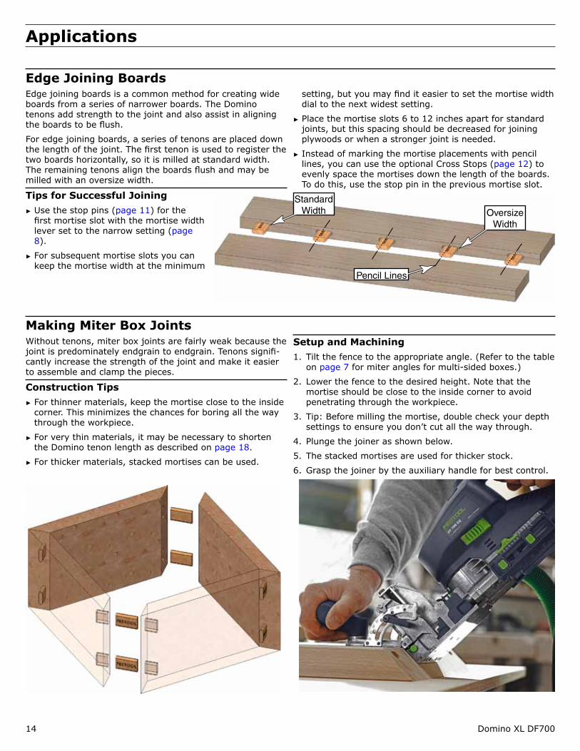
Edge Joining BoardsEdge joining boards is a common method for creating wide boards from a series of narrower boards. The Domino tenons add strength to the joint and also assist in aligning the boards to be flush.
For edge joining boards, a series of tenons are placed down the length of the joint. The first tenon is used to register the two boards horizontally, so it is milled at standard width. The remaining tenons align the boards flush and may be milled with an oversize width.
Tips for Successful Joining ► Use the stop pins (page 11) for the first mortise slot with the mortise width lever set to the narrow setting (page 8).
► For subsequent mortise slots you can keep the mortise width at the minimum
setting, but you may find it easier to set the mortise width dial to the next widest setting.
► Place the mortise slots 6 to 12 inches apart for standard joints, but this spacing should be decreased for joining plywoods or when a stronger joint is needed.
► Instead of marking the mortise placements with pencil lines, you can use the optional Cross Stops (page 12) to evenly space the mortises down the length of the boards. To do this, use the stop pin in the previous mortise slot.
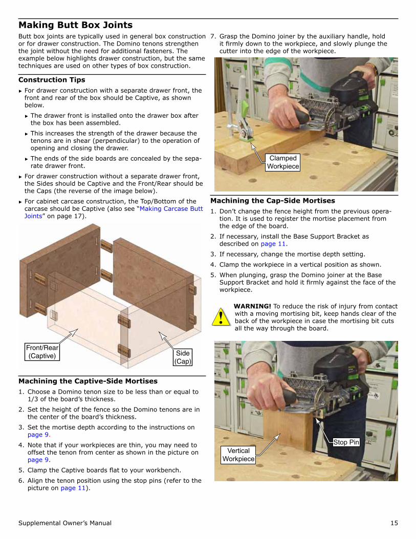
Making Miter Box JointsWithout tenons, miter box joints are fairly weak because the joint is predominately endgrain to endgrain. Tenons signifi-cantly increase the strength of the joint and make it easier to assemble and clamp the pieces.
Construction Tips ► For thinner materials, keep the mortise close to the inside corner. This minimizes the chances for boring all the way through the workpiece.
► For very thin materials, it may be necessary to shorten the Domino tenon length as described on page 18.
► For thicker materials, stacked mortises can be used.
Setup and Machining1. Tilt the fence to the appropriate angle. (Refer to the table
on page 7 for miter angles for multi-sided boxes.)
2. Lower the fence to the desired height. Note that the mortise should be close to the inside corner to avoid penetrating through the workpiece.
3. Tip: Before milling the mortise, double check your depth settings to ensure you don’t cut all the way through.
4. Plunge the joiner as shown below.
5. The stacked mortises are used for thicker stock.
6. Grasp the joiner by the auxiliary handle for best control.
Oversize Width
Standard Width
Pencil Lines
Supplemental Owner’s Manual 15
Making Butt Box JointsButt box joints are typically used in general box construction or for drawer construction. The Domino tenons strengthen the joint without the need for additional fasteners. The example below highlights drawer construction, but the same techniques are used on other types of box construction.
Construction Tips ► For drawer construction with a separate drawer front, the front and rear of the box should be Captive, as shown below.
► The drawer front is installed onto the drawer box after the box has been assembled.
► This increases the strength of the drawer because the tenons are in shear (perpendicular) to the operation of opening and closing the drawer.
► The ends of the side boards are concealed by the sepa-rate drawer front.
► For drawer construction without a separate drawer front, the Sides should be Captive and the Front/Rear should be the Caps (the reverse of the image below).
► For cabinet carcase construction, the Top/Bottom of the carcase should be Captive (also see “Making Carcase Butt Joints” on page 17).
Front/Rear (Captive) Side
(Cap)
Machining the Captive-Side Mortises1. Choose a Domino tenon size to be less than or equal to
1/3 of the board’s thickness.
2. Set the height of the fence so the Domino tenons are in the center of the board’s thickness.
3. Set the mortise depth according to the instructions on page 9.
4. Note that if your workpieces are thin, you may need to offset the tenon from center as shown in the picture on page 9.
5. Clamp the Captive boards flat to your workbench.
6. Align the tenon position using the stop pins (refer to the picture on page 11).
7. Grasp the Domino joiner by the auxiliary handle, hold it firmly down to the workpiece, and slowly plunge the cutter into the edge of the workpiece.
Clamped Workpiece
Machining the Cap-Side Mortises1. Don’t change the fence height from the previous opera-
tion. It is used to register the mortise placement from the edge of the board.
2. If necessary, install the Base Support Bracket as described on page 11.
3. If necessary, change the mortise depth setting.
4. Clamp the workpiece in a vertical position as shown.
5. When plunging, grasp the Domino joiner at the Base Support Bracket and hold it firmly against the face of the workpiece.
WARNING! To reduce the risk of injury from contact with a moving mortising bit, keep hands clear of the back of the workpiece in case the mortising bit cuts all the way through the board.
Stop PinVertical
Workpiece
16 Domino XL DF700
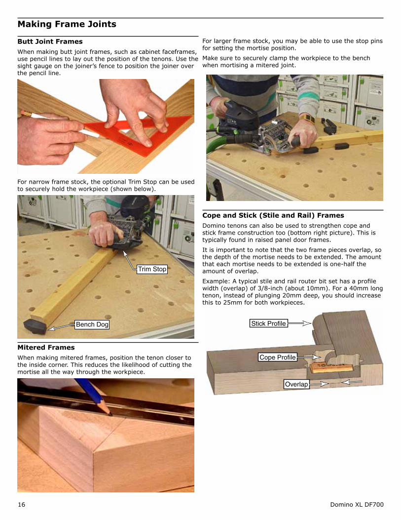
Making Frame Joints
Butt Joint FramesWhen making butt joint frames, such as cabinet faceframes, use pencil lines to lay out the position of the tenons. Use the sight gauge on the joiner’s fence to position the joiner over the pencil line.
For narrow frame stock, the optional Trim Stop can be used to securely hold the workpiece (shown below).
Trim Stop
Bench Dog
Mitered FramesWhen making mitered frames, position the tenon closer to the inside corner. This reduces the likelihood of cutting the mortise all the way through the workpiece.
For larger frame stock, you may be able to use the stop pins for setting the mortise position.
Make sure to securely clamp the workpiece to the bench when mortising a mitered joint.
Cope and Stick (Stile and Rail) FramesDomino tenons can also be used to strengthen cope and stick frame construction too (bottom right picture). This is typically found in raised panel door frames.
It is important to note that the two frame pieces overlap, so the depth of the mortise needs to be extended. The amount that each mortise needs to be extended is one-half the amount of overlap.
Example: A typical stile and rail router bit set has a profile width (overlap) of 3/8-inch (about 10mm). For a 40mm long tenon, instead of plunging 20mm deep, you should increase this to 25mm for both workpieces.
Stick Profile
Cope Profile
Overlap
Supplemental Owner’s Manual 17
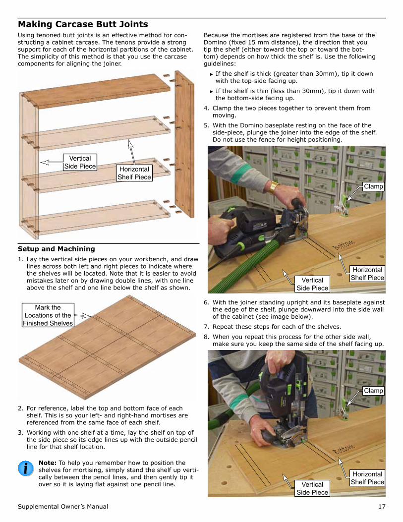
Making Carcase Butt JointsUsing tenoned butt joints is an effective method for con-structing a cabinet carcase. The tenons provide a strong support for each of the horizontal partitions of the cabinet. The simplicity of this method is that you use the carcase components for aligning the joiner.
Horizontal Shelf Piece
Vertical Side Piece
Setup and Machining1. Lay the vertical side pieces on your workbench, and draw
lines across both left and right pieces to indicate where the shelves will be located. Note that it is easier to avoid mistakes later on by drawing double lines, with one line above the shelf and one line below the shelf as shown.
Mark the Locations of the Finished Shelves
2. For reference, label the top and bottom face of each shelf. This is so your left- and right-hand mortises are referenced from the same face of each shelf.
3. Working with one shelf at a time, lay the shelf on top of the side piece so its edge lines up with the outside pencil line for that shelf location.
Note: To help you remember how to position the shelves for mortising, simply stand the shelf up verti-cally between the pencil lines, and then gently tip it over so it is laying flat against one pencil line.
Because the mortises are registered from the base of the Domino (fixed 15 mm distance), the direction that you tip the shelf (either toward the top or toward the bot-tom) depends on how thick the shelf is. Use the following guidelines:
► If the shelf is thick (greater than 30mm), tip it down with the top-side facing up.
► If the shelf is thin (less than 30mm), tip it down with the bottom-side facing up.
4. Clamp the two pieces together to prevent them from moving.
5. With the Domino baseplate resting on the face of the side-piece, plunge the joiner into the edge of the shelf. Do not use the fence for height positioning.
Bottom
Horizontal Shelf Piece
Clamp
Vertical Side Piece
6. With the joiner standing upright and its baseplate against the edge of the shelf, plunge downward into the side wall of the cabinet (see image below).
7. Repeat these steps for each of the shelves.
8. When you repeat this process for the other side wall, make sure you keep the same side of the shelf facing up.
Bottom
Horizontal Shelf Piece
Clamp
Vertical Side Piece
18 Domino XL DF700
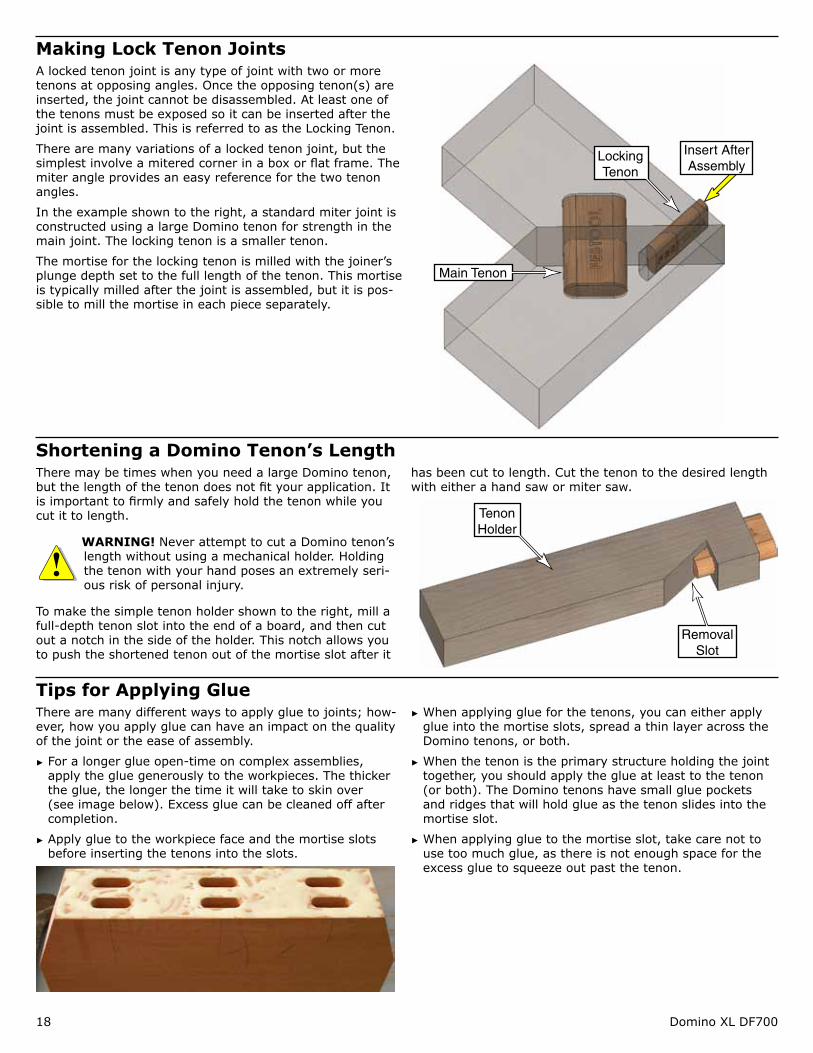
Making Lock Tenon JointsA locked tenon joint is any type of joint with two or more tenons at opposing angles. Once the opposing tenon(s) are inserted, the joint cannot be disassembled. At least one of the tenons must be exposed so it can be inserted after the joint is assembled. This is referred to as the Locking Tenon.
There are many variations of a locked tenon joint, but the simplest involve a mitered corner in a box or flat frame. The miter angle provides an easy reference for the two tenon angles.
In the example shown to the right, a standard miter joint is constructed using a large Domino tenon for strength in the main joint. The locking tenon is a smaller tenon.
The mortise for the locking tenon is milled with the joiner’s plunge depth set to the full length of the tenon. This mortise is typically milled after the joint is assembled, but it is pos-sible to mill the mortise in each piece separately.
Locking Tenon
Main Tenon
Insert After Assembly
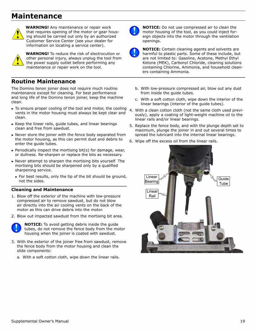
Shortening a Domino Tenon’s LengthThere may be times when you need a large Domino tenon, but the length of the tenon does not fit your application. It is important to firmly and safely hold the tenon while you cut it to length.
WARNING! Never attempt to cut a Domino tenon’s length without using a mechanical holder. Holding the tenon with your hand poses an extremely seri-ous risk of personal injury.
To make the simple tenon holder shown to the right, mill a full-depth tenon slot into the end of a board, and then cut out a notch in the side of the holder. This notch allows you to push the shortened tenon out of the mortise slot after it
has been cut to length. Cut the tenon to the desired length with either a hand saw or miter saw.
Tenon Holder
Removal Slot
Tips for Applying GlueThere are many different ways to apply glue to joints; how-ever, how you apply glue can have an impact on the quality of the joint or the ease of assembly.
► For a longer glue open-time on complex assemblies, apply the glue generously to the workpieces. The thicker the glue, the longer the time it will take to skin over (see image below). Excess glue can be cleaned off after completion.
► Apply glue to the workpiece face and the mortise slots before inserting the tenons into the slots.
► When applying glue for the tenons, you can either apply glue into the mortise slots, spread a thin layer across the Domino tenons, or both.
► When the tenon is the primary structure holding the joint together, you should apply the glue at least to the tenon (or both). The Domino tenons have small glue pockets and ridges that will hold glue as the tenon slides into the mortise slot.
► When applying glue to the mortise slot, take care not to use too much glue, as there is not enough space for the excess glue to squeeze out past the tenon.
Supplemental Owner’s Manual 19
Maintenance WARNING! Any maintenance or repair work that requires opening of the motor or gear hous-ing should be carried out only by an authorized Customer Service Center (see your dealer for information on locating a service center).
WARNING! To reduce the risk of electrocution or other personal injury, always unplug the tool from the power supply outlet before performing any maintenance or repair work on the tool.
NOTICE: Do not use compressed air to clean the motor housing of the tool, as you could inject for-eign objects into the motor through the ventilation openings.
NOTICE: Certain cleaning agents and solvents are harmful to plastic parts. Some of these include, but are not limited to: Gasoline, Acetone, Methyl Ethyl Ketone (MEK), Carbonyl Chloride, cleaning solutions containing Chlorine, Ammonia, and household clean-ers containing Ammonia.
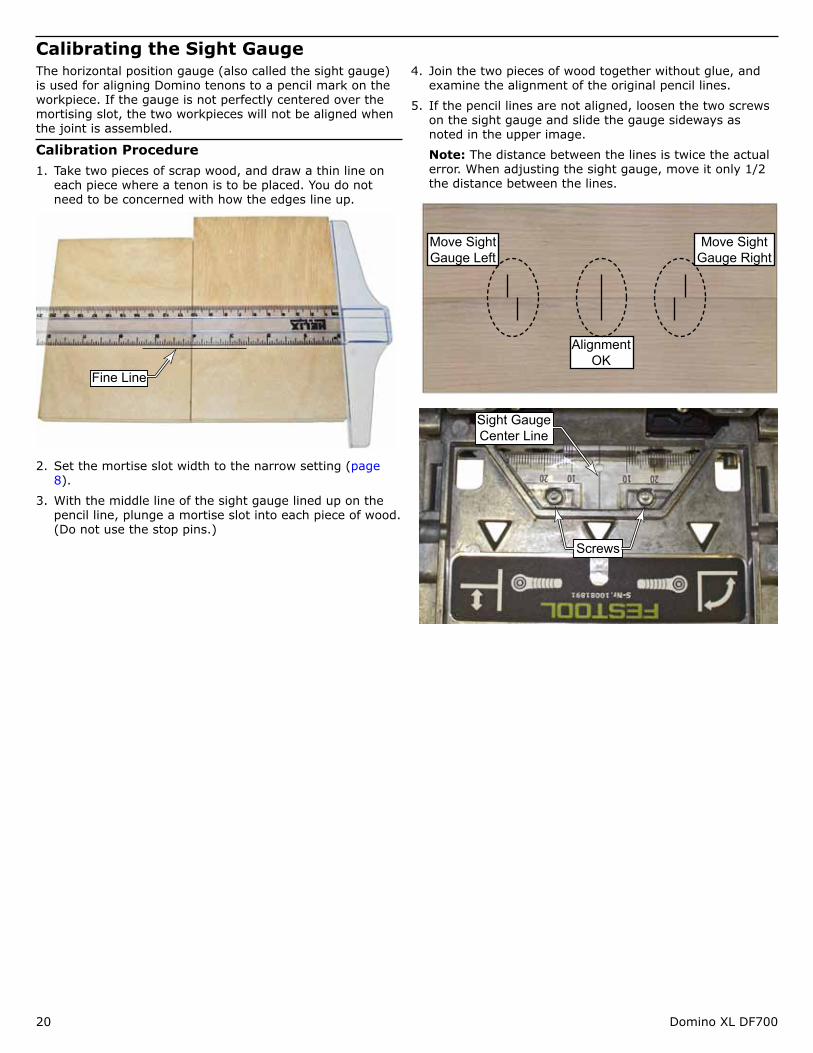
Routine MaintenanceThe Domino tenon joiner does not require much routine maintenance except for cleaning. For best performance and long life of the Domino tenon joiner, keep the machine clean.
► To ensure proper cooling of the tool and motor, the cooling vents in the motor housing must always be kept clear and clean.
► Keep the linear rails, guide tubes, and linear bearings clean and free from sawdust.
► Never store the joiner with the fence body separated from the motor housing, as this can permit dust and debris to enter the guide tubes.
► Periodically inspect the mortising bit(s) for damage, wear, or dullness. Re-sharpen or replace the bits as necessary.
► Never attempt to sharpen the mortising bits yourself. The mortising bits should be sharpened only by a qualified sharpening service.
► For best results, only the tip of the bit should be ground, not the sides.
Cleaning and Maintenance1. Blow off the exterior of the machine with low-pressure
compressed air to remove sawdust, but do not blow air directly into the air cooling vents on the back of the motor as this can drive debris into the motor.
2. Blow out impacted sawdust from the mortising bit area.
NOTICE: To avoid getting debris inside the guide tubes, do not remove the fence body from the motor housing when the joiner is coated with sawdust.
3. With the exterior of the joiner free from sawdust, remove the fence body from the motor housing and clean the slide components:
a. With a soft cotton cloth, wipe down the linear rails.
b. With low-pressure compressed air, blow out any dust from inside the guide tubes.
c. With a soft cotton cloth, wipe down the interior of the linear bearings (interior of the guide tubes).
4. With a clean cotton cloth (not the same cloth used previ-ously), apply a coating of light-weight machine oil to the linear rails and/or linear bearings.
5. Replace the fence body, and with the plunge depth set to maximum, plunge the joiner in and out several times to spread the lubricant into the internal linear bearings.
6. Wipe off the excess oil from the linear rails.
Guide Tube
Linear Bearing
Linear Rail
20 Domino XL DF700
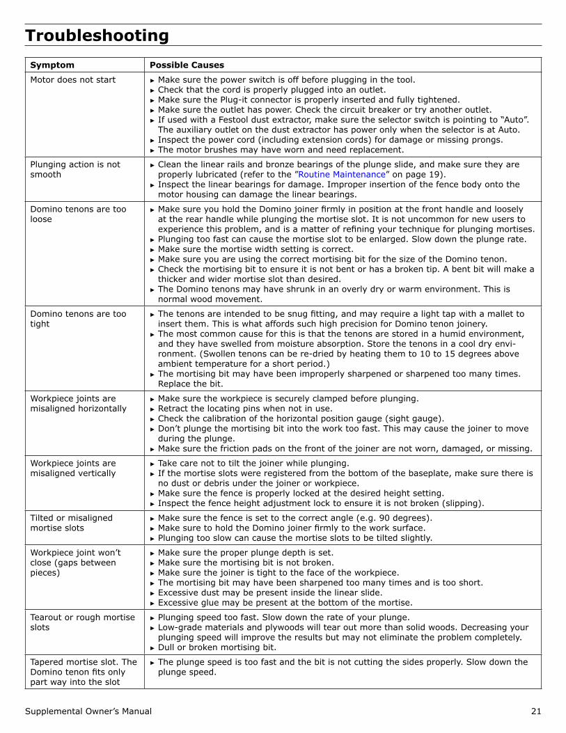
Calibrating the Sight GaugeThe horizontal position gauge (also called the sight gauge) is used for aligning Domino tenons to a pencil mark on the workpiece. If the gauge is not perfectly centered over the mortising slot, the two workpieces will not be aligned when the joint is assembled.
Calibration Procedure1. Take two pieces of scrap wood, and draw a thin line on
each piece where a tenon is to be placed. You do not need to be concerned with how the edges line up.
Fine Line
2. Set the mortise slot width to the narrow setting (page 8).
3. With the middle line of the sight gauge lined up on the pencil line, plunge a mortise slot into each piece of wood. (Do not use the stop pins.)
4. Join the two pieces of wood together without glue, and examine the alignment of the original pencil lines.
5. If the pencil lines are not aligned, loosen the two screws on the sight gauge and slide the gauge sideways as noted in the upper image.
Note: The distance between the lines is twice the actual error. When adjusting the sight gauge, move it only 1/2 the distance between the lines.
Move Sight Gauge Right
Move Sight Gauge Left
Alignment OK
Screws
Sight Gauge Center Line
Supplemental Owner’s Manual 21
TroubleshootingSymptom Possible Causes
Motor does not start ► Make sure the power switch is off before plugging in the tool. ► Check that the cord is properly plugged into an outlet. ► Make sure the Plug-it connector is properly inserted and fully tightened. ► Make sure the outlet has power. Check the circuit breaker or try another outlet. ► If used with a Festool dust extractor, make sure the selector switch is pointing to “Auto”. The auxiliary outlet on the dust extractor has power only when the selector is at Auto.
► Inspect the power cord (including extension cords) for damage or missing prongs. ► The motor brushes may have worn and need replacement.
Plunging action is not smooth
► Clean the linear rails and bronze bearings of the plunge slide, and make sure they are properly lubricated (refer to the ”Routine Maintenance” on page 19).
► Inspect the linear bearings for damage. Improper insertion of the fence body onto the motor housing can damage the linear bearings.
Domino tenons are too loose
► Make sure you hold the Domino joiner firmly in position at the front handle and loosely at the rear handle while plunging the mortise slot. It is not uncommon for new users to experience this problem, and is a matter of refining your technique for plunging mortises.
► Plunging too fast can cause the mortise slot to be enlarged. Slow down the plunge rate. ► Make sure the mortise width setting is correct. ► Make sure you are using the correct mortising bit for the size of the Domino tenon. ► Check the mortising bit to ensure it is not bent or has a broken tip. A bent bit will make a thicker and wider mortise slot than desired.
► The Domino tenons may have shrunk in an overly dry or warm environment. This is normal wood movement.
Domino tenons are too tight
► The tenons are intended to be snug fitting, and may require a light tap with a mallet to insert them. This is what affords such high precision for Domino tenon joinery.
► The most common cause for this is that the tenons are stored in a humid environment, and they have swelled from moisture absorption. Store the tenons in a cool dry envi-ronment. (Swollen tenons can be re-dried by heating them to 10 to 15 degrees above ambient temperature for a short period.)
► The mortising bit may have been improperly sharpened or sharpened too many times. Replace the bit.
Workpiece joints are misaligned horizontally
► Make sure the workpiece is securely clamped before plunging. ► Retract the locating pins when not in use. ► Check the calibration of the horizontal position gauge (sight gauge). ► Don’t plunge the mortising bit into the work too fast. This may cause the joiner to move during the plunge.
► Make sure the friction pads on the front of the joiner are not worn, damaged, or missing.
Workpiece joints are misaligned vertically
► Take care not to tilt the joiner while plunging. ► If the mortise slots were registered from the bottom of the baseplate, make sure there is no dust or debris under the joiner or workpiece.
► Make sure the fence is properly locked at the desired height setting. ► Inspect the fence height adjustment lock to ensure it is not broken (slipping).
Tilted or misaligned mortise slots
► Make sure the fence is set to the correct angle (e.g. 90 degrees). ► Make sure to hold the Domino joiner firmly to the work surface. ► Plunging too slow can cause the mortise slots to be tilted slightly.
Workpiece joint won’t close (gaps between pieces)
► Make sure the proper plunge depth is set. ► Make sure the mortising bit is not broken. ► Make sure the joiner is tight to the face of the workpiece. ► The mortising bit may have been sharpened too many times and is too short. ► Excessive dust may be present inside the linear slide. ► Excessive glue may be present at the bottom of the mortise.
Tearout or rough mortise slots
► Plunging speed too fast. Slow down the rate of your plunge. ► Low-grade materials and plywoods will tear out more than solid woods. Decreasing your plunging speed will improve the results but may not eliminate the problem completely.
► Dull or broken mortising bit.
Tapered mortise slot. The Domino tenon fits only part way into the slot
► The plunge speed is too fast and the bit is not cutting the sides properly. Slow down the plunge speed.