Page 1
Donor-Acceptor dyads for molecular
rectifying devices
Mykola Kondratenko
Department of Chemistry
McGill University
Montreal, Quebec
Canada
June 2011
A Thesis submitted to McGill University
In partial fulfillment of requirements for the degree of Doctor of Philosophy
Mykola Kondratenko 2011
Page 3
ii
Abstract
The interest in molecular electronics began in the 1970s with the work of Aviram
and Ratner, who proposed that a donor-acceptor dyad, specifically TTF––TCNQ
molecule (TTF–tetrathiafulvalene, –nonconjugated bridge and TCNQ–
tetracyanoquinodimethane), can resemble the electric properties of a p-n junction, acting
as a unimolecular diode. The reason of such behaviour lies in asymmetrically distributed
electronic levels, and very low HOMO-LUMO gap (0.3 eV) that was imposed for the
model molecule. Up to date, numerous donor-acceptor dyads were investigated as
candidates for molecular rectifiers, which included some D––A dyads with weak or
moderate donor and acceptor moieties, numerous D––A and also molecules without
obvious asymmetry in the electronic structure. However, neither the original TTF––
TCNQ molecule nor any other molecule with similar HOMO–LUMO gap have been
studied in molecular electronics applications, which was due to synthetic unavailability
of such molecules.
In this thesis we present molecular design, synthesis as well as characterization
of series of Donor-Acceptor dyads with different combinations of well studied
electroactive moieties (TTF--fluorene, nEDOT-3CNQ, nEDOT-NDI). Herein we
describe our progress towards the main synthetic challenge in the field of molecular
rectifiers – coupling together strong donor and strong acceptor molecules. To achieve
this we employed different synthetic strategies, namely, use of intermediates with
moderated redox properties and highly reactive derivatives to avoid formation of charge-
transfer complexes between donor and acceptor as well as utilization of the donor-
acceptor complexation which results their covalent binding. The synthetic design
includes two types of approaches allowing binding the dyad molecules to electrode
surface: (1) amphiphilic structure which enables deposition of molecular monolayers via
Langmuir-Blodgett technique and (2) thiol/disulfide functionality suitable for covalent
grafting of molecules to metals. Characterization of such monolayers by different
spectroscopic and electrochemical techniques as well as analysis of the alignment and
packing of the molecules within the films and monolayers stability are discussed.
Finally, we describe fabrication of Electrode/Organic monolayer/Electrode junctions and
Page 4
iii
discuss results of the charge transport measurements of the synthesized donor-acceptor
dyads.
Page 5
iv
Résumé
L'intérêt pour l'électronique moléculaire a commencé dans les années 70, avec la
découverte d'Aviram et de Ratner. Ils ont proposé une dyade donneur-accepteur telle que
la molécule TTF––TCNQ (TTF–tetrathiafulvalene, liaisons isolées et TCNQ–
tetracyanoquinodimethane) qui pourrait fonctionner comme une jonction p-n, jouant le
rôle d'une diode unimoléculaire. Ce phénomène est dû à une distribution asymétrique
des niveaux électroniques, ainsi qu'au très faible écart HOMO-LUMO (0.3 eV) de cette
molécule. Jusqu'à présent, un grand nombre de dyades donneur-accepteur ont été
étudiées comme candidates pour la synthèse de redresseurs moléculaires. Ceux-ci
incluent certaines dyades D––A avec des groupes donneur et accepteur faibles ou
modérés, de nombreux dyades D––A, ainsi que des molécules ayant une forte
asymétrie dans leur structure électronique.
Dans cette thèse, nous présentons la conception moléculaire, la synthèse et la
caractérisation d'une série de donneur-accepteurs avec de différentes combinaisons de
groupes connus comme étant électroactifs (TTF--fluorene, nEDOT-3CNQ, nEDOT-
NDI). Nous décrivons les progrès que nous avons apportés au domaine complexe de
redresseurs moléculaires par l’entremise du couplage de puissant donneurs et accepteurs.
Pour réussir cela, nous avons employé différentes stratégies dont: l'utilisation
d'intermédiaires avec des propriétés oxido-réductives modérées et des dérivés très
réactifs pour empêcher la formation de complexes à transfert de charge ainsi que de se
servir de ces mêmes complexe pour obtenir des liaisons covalentes. La synthèse utilisée
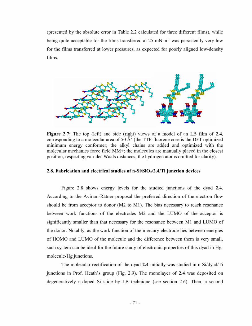
explore deux approches qui permettent la liaison des dyades à la surface de l'électrode:
(1) l'utilisation de structures amphiphiles permettant la déposition de monocouches
moléculaires par la technique Langmuir-Blodgett et (2) l'utilisation de groupes de thiol
et dedisulfure permettant la liaison covalente des molécules avec des métaux. La
caractérisation de ces monocouches a été fait à l’aide de techniques spectroscopiques et
électrochimiques.L'analyse de la densité, l'ordre des molécules dans les films et leur
stabilité a aussi été étudié. Finalement, nous décrivons la fabrication de jonctions
électrode/monocouche organique/électrode et nous discutons les résultats des mesures de
transport de charges des dyades donneur-accepteur synthétises.
Page 6
v
Acknowledgments
I heartily thank my supervisor, Prof. D. Perepichka, without who's
encouragement, guidance and support from the very beginning to the final editing
stages, this theses would not be possible. I would also like to thank him for his help in
fostering my understanding of the subject and his patience with me as I developed my
organic synthesis skills, through the characterization of the monolayers and a great many
experiments.
During my study I also have been lucky to work with some remarkable people at
Laval University, INRS-EMT and of course, in D. Perepichka’s group. My special
thanks to Karin Arseneault (group of M. Pezolet, Laval University) who introduced me
to Langmuir-Blodgett technique. I am also grateful to Jacky Brusso, Matt Morantz, Julia
Schneider, Andrey Moiseev and Afshin Dadvand for many helpful discussions and
proof-reading my manuscripts.
I would also like to thank the many people who have helped me during my stay
at McGill University. First of all, I’m grateful to Chantal Marotte for her guidance
during my graduate studies. I would like to recognize the inestimable help of Fred Morin
and Nadim Saade with the characterization of new materials; Fred Kluck, Jean-Philippe
Guay, Richard Rossi and Weihua Wang for their help in building, breaking, and fixing
the tools that made my research easier.
Finally I would like to thank my family for their support, understanding and
encouragement through all these years.
Page 7
vi
Table of contents
Abstract ............................................................................................................................ ii
Résumé ............................................................................................................................ iv
Acknowledgments ........................................................................................................... v
List of abbreviations ...................................................................................................... ix
Introduction .................................................................................................................. - 1 -
Motivations and objectives ........................................................................................ - 3 -
Outline of the thesis .................................................................................................... - 4 -
Chapter I: Overview: Unimolecular organic rectifiers .......................................... - 6 -
1.1 Aviram-Ratner concept ................................................................................ - 6 -
1.2 Experimental works in the field of unimolecular rectifiers ............................. - 13 -
1.2.1 Donor--Acceptor molecules .................................................................... - 13 -
1.2.2 Donor-π-Acceptor molecules .................................................................... - 17 -
1.2.3. Non Donor-Acceptor rectifying systems ................................................. - 21 -
1.2.4 Synthetic strategies for donor-acceptor dyads .......................................... - 28 -
1.3 Molecular assemblies ....................................................................................... - 31 -
1.3.1 Langmuir-Blodgett deposition .................................................................. - 32 -
1.3.2 Self-assembly by chemisorption ............................................................... - 36 -
1.4 Characterization of organic monolayers .......................................................... - 39 -
1.4.1 Ellipsometry .............................................................................................. - 39 -
1.4.2 Contact angle ............................................................................................. - 40 -
1.4.3 Reflection-absorption and ATR infrared spectroscopy ............................. - 41 -
1.4.5 Electrochemical characterization of SAMs ............................................... - 45 -
1.5. Fabrication of molecular junctions ................................................................. - 47 -
1.5.1 Vacuum deposition of the metal on top of the organic layer .................... - 48 -
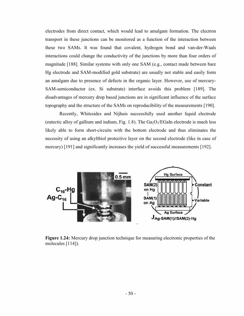
1.5.2 Liquid metals drop junctions ..................................................................... - 49 -
1.5.4 Electron Transfer in Metal-Molecule-Metal Junctions ............................. - 51 -
Conclusions ............................................................................................................ - 54 -
Chapter II. The first studies of a tetrathiafulvalene-σ-acceptor molecular
rectifiers .................................................................................................................... - 55 -
Introduction ............................................................................................................ - 55 -
Page 8
vii
2.1. ―Amphiphilic design‖ ..................................................................................... - 57 -
2.2. Synthesis of TTF--fluorene dyads ................................................................ - 57 -
2.3. Geometry and electronic structure of the dyad 2.4 ......................................... - 59 -
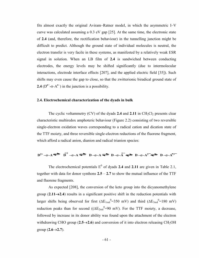
2.4. Electrochemical characterization of the dyads in bulk ................................... - 61 -
2.5. Preparation of monolayer of 2.4 on air-water interface .................................. - 63 -
2.6. Deposition of the monolayers on solid substrates ........................................... - 65 -
2.7. Spectroscopic characterization of LB monolayers.......................................... - 66 -
2.8. Fabrication and electrical studies of n-Si/SiO2/2.4/Ti junction devices ......... - 71 -
2.9. Fabrication and electrical studies of Au/2.4/Hg junction devices .................. - 76 -
Conclusions ............................................................................................................ - 79 -
Experimental section .............................................................................................. - 80 -
Chapter III. Self-Assembled Monolayers of Strong Electron Acceptors:
Polynitrofluorenes on Gold ..................................................................................... - 83 -
Introduction ............................................................................................................ - 83 -
3.1 Synthesis .......................................................................................................... - 84 -
3.2 Formation of SAMs of the fluorene derivatives 3.4 and 3.5............................ - 87 -
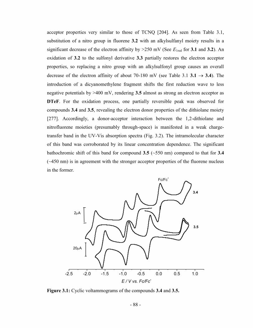
3.3. Electrochemical and spectroscopic characterizations of 3.4 and 3.5 in solution- 87
-
3.4 Electrochemistry of SAMs ............................................................................... - 91 -
3.5 Reflectance-absorbance infrared spectroscopy (RAIRS) of SAMs ................. - 96 -
3.6 Ellipsometry and contact angle measurements ................................................ - 98 -
3.7. Rectification study of dyad 3.5 ....................................................................... - 99 -
Conclusions .......................................................................................................... - 103 -
Experimental Part ................................................................................................. - 104 -
Chapter IV. Synthesis and characterization of TTF--nitrofluorene dyads for self-
assembly on gold surface. ...................................................................................... - 107 -
Introduction .......................................................................................................... - 107 -
4.1. Synthesis ....................................................................................................... - 107 -
4.2. Characterization ............................................................................................ - 117 -
Conclusions .......................................................................................................... - 123 -
Experimental Part ................................................................................................. - 124 -
Page 9
viii
Chapter V. Molecular rectification of hexyl-nEDOT-3CNQ dyads in Langmuir-
Blodgett film ........................................................................................................... - 130 -
Introduction .......................................................................................................... - 130 -
5.1. Synthesis ....................................................................................................... - 131 -
5.2. DFT Calculations .......................................................................................... - 136 -
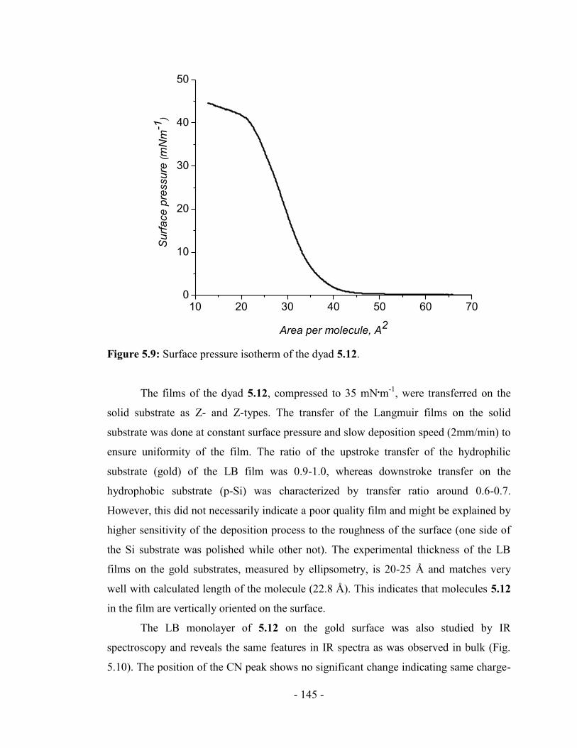
5.3. Characterization ............................................................................................ - 138 -
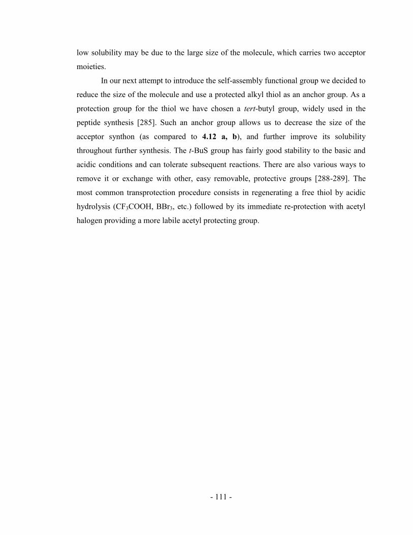
5.4. Langmuir-Blodgett deposition of the monolayer of 5.12 on the solid
substrates .............................................................................................................. - 143 -
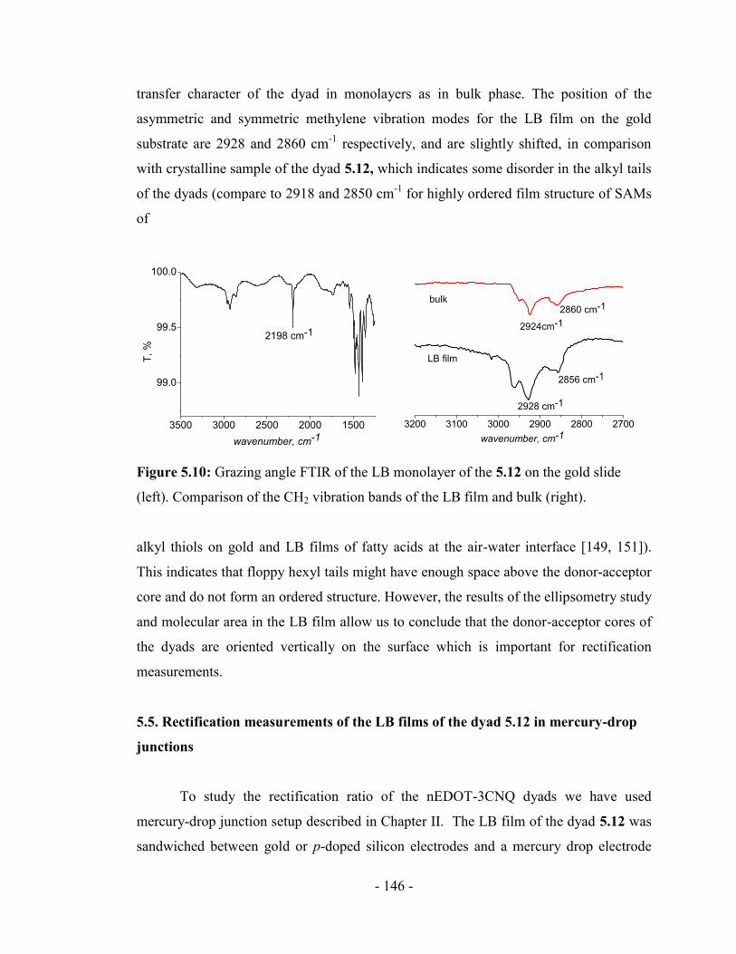
5.5. Rectification measurements of the LB films of the dyad 5.12 in mercury-drop
junctions ............................................................................................................... - 146 -
Conclusions .......................................................................................................... - 152 -
Experimental part ................................................................................................. - 153 -
Chapter VI. Stable nEDOT-NDI molecular rectifiers with self-assembly
capability. ................................................................................................................ - 156 -
Introduction .......................................................................................................... - 156 -
6.1. Synthesis of nEDOT-NDI dyads ................................................................... - 158 -
6.2. Calculations ................................................................................................... - 160 -
6.3. Absorption/Emission spectra ........................................................................ - 161 -
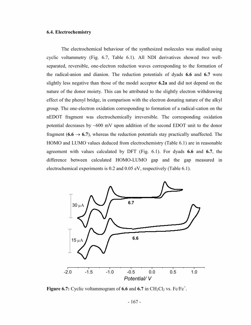
6.4. Electrochemistry ........................................................................................... - 167 -
6.5. SAM preparation and characterization ......................................................... - 172 -
6.6. Preliminary rectification study of the bis-EDOT-NDI dyads ....................... - 177 -
6.7. Potential for improvement of the acceptor properties ................................... - 181 -
Experimental part ................................................................................................. - 184 -
Conclusions ............................................................................................................. - 189 -
References ............................................................................................................... - 192 -
Appendix ................................................................................................................. - 229 -
Author’s contribution ............................................................................................ - 235 -
List of publications ................................................................................................. - 237 -
Page 10
ix
List of abbreviations
A Acceptor
Ac Acetyl
AFM Atomic force microscope
AR Aviram-Ratner
ATR Attenuated total reflection
CTC Charge-transfer complex
CV Cyclic Voltammetry
D Donor
DCC N,N'-dicyclohehylcarbodiimide
DMAP 4-Dimethylaminopyridine
DTeF 9-dicyanomethylene-2,4,5,7-tetranitrofluorene
DFT Density functional theory
EDOT 3,4-Ethylenedioxythiophene
Et ethyl
FT-IR Fourier transform infrared spectroscopy
Fc Ferrocene
HOMO Highest occupied molecular orbital
HLG HOMO-LUMO gap
LB Langmuir-Blodgett
LUMO Lowest unoccupied molecular orbital
Me methyl
NDI 1,4,5,8-naphthalenetetracarboxylic diimide
NMR Nuclear magnetic resonance spectroscopy
Ph phenyl
PDI 3,4,9,10-Perylenetetracarboxylic diimide
Page 11
x
PTCDA 3,4,9,10-Perylenetetracarboxylic dianhyride
RR Rectification ratio
SAM Self-assembled monolayer
STM Scanning tunneling microscopy
STS Scanning tunneling spectroscopy
TCNQ Tetracyanoquinodimethane
TLC Thin-layer chromatography
TNF 2,4,5,7-tetranitrofluorene-9-one
TTF Tetrathiafulvalene
UV Ultra-violet spectroscopy
Page 12
- 1 -
Introduction
Molecular electronics can be defined as a field of research that studies electrical
processes in a single or at least in a limited number of molecules. This also involves the
study of a wide number of different molecular assemblies of any scale and organization
and the application of organic and biological molecules in electronic devices.
Richard Feynman was the first scientist to point out on the perspective future of
molecular-scale systems in his famous speech, ―There is Plenty of Room at the Bottom‖
in the 1950s. He brought attention to the point that physical laws do not limit the ability
to manipulate and study single molecules and even atoms. He correctly noted simply the
lack of instrumentation for doing so and predicted that in a near future it would be
possible to perform atomically precise manipulations [1].
Today, molecular electronics is an important multidisciplinary field in the
fundamental theoretical research of the physical and electrochemical properties of
organic materials and the application of such materials in novel electronic devices [2-4].
One of the reasons that molecular electronics has attracted so much attention was the
hope that single molecules could possibly become an alternative for the present silicon-
based integrated circuits. In 1965, Gordon Moore from Intel has quantitatively described
the trend of the computer’s power growth By making an observation, made in 1965, was
that the number of transistors per unit area on integrated circuits, or functionality per
chip, doubles every 2-3 years since the integrated circuit was invented [5]. He also
predicted that this trend would continue in the foreseeable future. This is achieved by
reducing the size of devices. Over the past decades, silicon based devices has continually
been scaled down in size. In late 2009, Intel began production of a process featuring a
32 nm feature size. But this minimization cannot go on forever and eventually
technology will face hard technical difficulties. The organic molecules, with size 1-3 nm
can possibly do similar tasks that current silicon-based devices are doing. Molecular
electronics involves a bottom-up technology that uses atoms to build nanometre-sized
molecules that could further self-assemble into a desired computational circuitry. This
bottom-up approach gives rise to the prospect of manufacturing electronic circuits in
rapid, cost-efficient, flow-through processes.
Page 13
- 2 -
Two main focuses in the field of molecular electronics are: design and synthesis
of the molecular-scale systems with tailored electronic properties and the study of such
systems as electronic devices for processing electrical, optoelectronic and other signals.
Bulk organic materials are already widely utilized in thin-film electronics and successful
application of such materials is a rather developed field. Organic light-emitting diodes
[6-7], organic field effect transistors [8-12] and photovoltaic cells [13-14] are already on
the market.
There are, of course, a number of challenges related to the use of the single
organic molecules as electronic device.
Organic molecules are easier to synthesize in large quantities then it is to
manufacture the Si based devices, but they are more difficult to arrange on a surface or
in a three-dimensional array using existing technologies (e.g. Photolithography). It is
also difficult to ensure that the molecules stay in place.
The stability and life-time of the organic molecules can be an issue as
well. The heat dissipation becomes very important consideration for the electronic
devices with a million-fold increase in circuit density. Thus, extremely efficient cooling
systems would be needed to prevent decomposition of the molecule and damage of the
device.
To address these challenges the development of new technology together with
scientific understanding of the processes in single molecules could make progress
towards molecular electronics possible. Nowadays, synthesis of organic molecules is a
highly developed tool and by choosing different compositions and geometries it is easy
to vary a molecule’s charge transport, binding, electrical, and structural properties. The
size scale of organic molecules lies between 1 and 100 nm, a scale that permits
functional nanostructures with accompanying advantages in cost, efficiency, and power
dissipation. The advantages of specific intermolecular interactions allow formation of
nanoscale structures by self-assembly.
Page 14
- 3 -
Motivations and objectives
In 1974 Ari Aviram and Mark Ratner proposed a theoretical concept of
unimolecular rectification and this work brought an attractive idea for development
systems that can potentially compete with today’s electronic devices. Although
numerous experimental strategies to achieve rectification in donor–acceptor molecules
have been attempted and various molecular structures, electrodes, and junction assembly
approaches have been tested, the precise mechanism for the rectification in molecular
junctions is still a subject of controversy.
The main objective of this thesis is molecular design and experimental study of
the unimolecular rectification of series of donor-acceptor molecules. For this purpose a
set of three donors and three acceptors were chosen to test testing the mechanism
proposed in the original Aviram-Ratner (AR) concept. Two approaches of depositing the
molecules on the electrode surface were employed in this work: Langmuir-Blodgett
deposition of the amphiphilic molecular structures and self-assembly of the thiol-
functionalized molecules. Different methods of assembly allow comparison of electrical
properties of molecules with different types of metal-molecule contacts. The electrode
surface, modified with the electroactive molecules were studied by different
spectroscopic and electrochemical methods was conducted during the course of this
work in order to get complete information about the chemical composition and structure
of the monolayers. Electron transfer through the monolayers of the dyads was studied in
metal-molecule-metal junctions made by thermal evaporation of the second electrode on
top of the organic film and by mercury drop technique. Comparison of the results may
illuminate details of the electron transport mechanisms of the single molecules.
Page 15
- 4 -
Outline of the thesis
In the first Chapter we present an introduction to the field of molecular
rectification where we discuss general concepts, previously published experimental
results and current progress in the field. Also we present an attempt to systematize
important ―tools‖ and challenges in this field (synthesis, assembling of the molecules on
the electrode surface, characterization of the monolayers and fabrication of the
molecular junctions).
Chapter II discusses synthesis, characterization and rectification study of TTF--
nitrofluorene based dyad with amphiphilic structure. The charge transport of this dyad
was studied in LB films sandwiched between two metal electrodes. Confirmation of
molecular origin of rectification behaviour of this molecule in metal-dyad-metal
junctions was also presented.
In the Chapter III we discuss self-assembly of electroactive molecules on the
electrode surface via chemical grafting of organic molecule on metal. Therein we
present the synthesis and study of monolayer self-assembly study of the poly-
nitrofluorene acceptor on metal surfaces.
Chapter IV focuses on the synthesis of the TTF--nitrofluorene based dyads with
self-assembly functionality and discusses in details the challenges associated with it.
There we present design, synthesis and characterization of the series of new TTF--
nitrofluorene based dyads with different thiol terminated functional groups.
In the Chapter V we present different design of donor-acceptor dyad based on
nEDOT-3CNQ. Synthesis and characterization of the molecules in bulk and as LB
monolayers on the solid substrate as well as rectification study of LB films are
discussed.
Finally, in the Chapter VI we discuss synthesis, characterization and rectification
properties of series another nEDOT containing donor-acceptor dyads with NDI as and
acceptor moiety.
In Conclusion section we summarize experimental results obtained during the
course of this work.
Page 16
- 5 -
Appendix includes preliminary theoretical and experimental results towards
improving the acceptor properties in the Donor-Acceptor dyads described in the Chapter
VI.
Page 17
- 6 -
Chapter I: Overview: Unimolecular organic rectifiers
A rectifier is an electrical device that converts alternating current (AC) to direct
current (DC) by allowing the current to flow only in one direction. The process is called
rectification and is the main function of conventional diodes. Diodes were the first
semiconductor electronic devices and are currently the key components of integrated
circuits along with transistors, resistors, capacitors and other electronic components. A
conventional diode is made of a crystal of semiconducting material that has impurities
added to it to create a region on one side that contains negative charge carriers
(electrons), called an n-type semiconductor, and a region on the other side that contains
positive charge carriers (holes), called a p-type semiconductor. Today most diodes are
made of silicon but sometimes other semiconductors such as germanium are used,
however, this is not an exhaustive description of present types of diodes [15].
The main parameter that characterizes performance of diode-like devices is the
rectification ratio (RR), which is obtained from the ratio of the current at equal voltages
of opposite sign:
|
| (1.1)
The RR of silicon-based diodes is usually in the range of a few hundred [16-17].
1.1 Aviram-Ratner concept
For decades researchers have been studying electron transport within large
molecules. In the 1950s, Henry Taube proved that electron transfer across an organic
bridge between two dissimilar metal ions occurs more slowly across aliphatic bridges
than across conjugated aromatic bridges [18]. This launched extensive studies of
intramolecular electron transfer in molecules in solution by fluorescence and time-decay
spectroscopy. Theoretical understanding of electron transfer was developed by Rudolph
A. Marcus, Noel S. Hush, and others [19-21]. ―Marcus theory‖ explains the rates of
Page 18
- 7 -
electron transfer reactions, – a process by which an electron can move by ―hopping‖
from one chemical species (called the electron donor) to another (called the electron
acceptor). The basic equation of Marcus theory is built on the classical Arrhenius
equation and is expressed as:
(
) (1.2)
where λ is the reorganization energy, Go is the total Gibbs free energy change for
electron transfer between A and B, and kb is the Boltzmann constant.
According to this equation, the electron-transfer rate will increase with increasing
the driving force (-∆G°) of the reaction (―normal case‖) up to a maximum when -∆G° =
λ (―optimal case‖), but decreases when -∆G° exceeds λ (―inverted case‖). Experimental
proof of this inverted region was obtained by Gerhard Closs, John R. Miller, and co-
workers by measuring the rate of electron transfer for a series of D--A dyads [22-24].
Marcus theory was used to describe a number of important processes in
chemistry and biology, including photosynthesis, corrosion, certain types of
chemiluminescence, charge separation in some types of solar cells and more.
The electron-transfer theory could be employed as a basis for understanding the
functioning of electronic devices of molecular size. Particularly, the one-way electron
transport within organic molecules is a subject of current interest in the field of
unimolecular diodes. The idea of unimolecular rectifiers was first proposed in 1974 by
Ari Aviram and Mark Ratner [25]. This publication was the first theoretical proposal
that started the field of molecular electronics. Aviram-Ratner proposed diode-like
behaviour from the junction based on a single D--A molecule (1.1) composed of
tetrathiafulvalene (TTF) and tetracyanoquinodimethane (TCNQ) – a good electron donor
[26] and acceptor [27], respectively – connected through an insulating saturated bridge
(-bridge). Electrical conduction within molecule 1.1 would be favoured from the
electron-poor moiety to the electron-rich moiety, but disfavoured in the reverse
direction. The purpose of the -bridge is to isolate the HOMO from the LUMO which
Page 19
- 8 -
are mainly localized on the donor and acceptor moieties, respectively. Thus, the bridge
physically prevents the molecular orbitals of the donor and acceptor from mixing and
provides asymmetry of the electronic structure of the dyad.
The rectifying behaviour of the D-A dyad can be easier understood from the
energy band diagram (Fig. 1.1). Figure 1.1 (A) presents the molecular energy levels of
an ideal rectifying molecule, when it is placed between two electrodes with no external
bias applied. The LUMO of the acceptor should lies close to the Fermi energy of the
cathode (or slightly above) whereas the LUMO of the donor lies as high as possible
above the Fermi energy of the anode. As well, the HOMO of the donor should lie close
to the Fermi energy of the anode. For the current to flow, electrons must tunnel through
the potential barriers between the molecule and electrodes as well as through the -
bridge.
Application of external bias to the junction leads to overlap of the work functions
of the electrodes with the molecular orbitals of the donor and acceptor moieties. Under
forward bias (Fig. 1.1 (B)), an electron travels from the Fermi level of the cathode to the
empty LUMO of the acceptor. A similar process takes place on the other side of the
junction – an electron is transferred from the occupied HOMO of the donor to the anode.
Injection of electrons and holes into TTF and TCNQ from electrodes will create the first
exited state followed by intramolecular electron transfer to form the ground state via
inelastic tunneling through the –bridge. The efficiency of the tunnelling increases when
HOMO and LUMO orbitals are close enough energetically (i.e., small HOMO-LUMO
gap). This electron transfer is irreversible by nature of the molecule’s energy levels, as
Page 20
- 9 -
the LUMO is higher in energy than the HOMO. Now, if we apply a reverse bias to the
same junction (Fig. 1.2), a much higher voltage is required to bring the Fermi level of
the cathode in resonance with the LUMO of the donor and the Fermi level of the anode
in resonance with the HOMO of the acceptor [21]. Comparing diagram B in Fig 1.1 with
diagram C in Fig 1.2 we can see that simply applying the same voltage in the reverse
direction cannot induce the resonance between the anode and the LUMO energy level of
the donor moiety. This is a classical interpretation of the behaviour of molecular diodes.
This electron transfer in the donor-acceptor molecule is well explained by
Marcus theory [19]. The rate of the electron transfer will increase as the energy
difference between the HOMO of donor and LUMO of acceptor is increasing, but only
until a certain point. Past that point, the electron transfer rate will actually decrease as
the energy difference continues to increase – this is called the ―Marcus inverted region".
The electron transfer at reverse bias and through large HOMO-LUMO gap is actually in
this inverted region, where the difference between LUMO of the donor and HOMO of
the acceptor is large.
Since molecule 1.1 has never been synthesised, there is no experimental evidence
for the rectification behaviour of this specific molecule. However, theoretical
calculations (INDO semi-empirical method) of the I-V characteristics for the 1.1
(EHOMO= 5.3 eV, ELUMO=5.0 eV) placed between two electrodes (=5.1 eV) [25] (Fig.
1.3) predict its rectification behaviour. The threshold potential for current passage,
determined as the voltage necessary for an overlap of the HOMO (D) and LUMO (A)
with corresponding Fermi levels of electrodes, is around 0.3 V. If the reverse bias
voltage is high enough (0.55 V for the system presented in [25]) to allow the overlap of
the LUMO of donor and HOMO of acceptor moieties with respective electrode, than the
current begins to flow in opposite direction.
It is important to note that the original concept also allows a second, potentially
possible, competing process called ―autoionization‖. In this case, the first step involves
internal tunneling of the electron from the HOMO of the donor onto the LUMO of the
acceptor resulting in formation of an exited state (i.e., a ―zwitterion‖). The electron
transfer then occurs in a second step across the molecule–electrode interface [25, 28].
According to this mechanism the electron would be transferred in the opposite direction,
Page 21
- 10 -
Figure 1.1: The energy band diagrams of the Aviram-Ratner concept of molecular
rectifiers. The D--A molecule is placed between two electrodes with A) no external
bias and B) a small forward bias.
Page 22
- 11 -
Figure 1.2: The energy band diagrams of Aviram-Ratner concept of molecular rectifier
at reverse bias.
Figure 1.3: Calculated I-V characteristics of the Aviram-Ratner molecular rectifier.
Copied from [25].
Page 23
- 12 -
from the electrode close to the donor onto the electrode close to the acceptor. However,
this alternative mechanism also involves a threshold voltage necessary to bring the
HOMO of the donor and the LUMO of the acceptor to the same energy levels before
internal tunnelling may occur [25]. Thus, a molecular rectifier must be designed with the
knowledge that the pathway for which the threshold voltage is smallest will define the
preferential direction of conductance.
Herein we briefly summarize most important issues in studying unimolecular
rectification.
(1) Synthesis of the rectifying dyads requires coupling together a strong
oxidizing agent (acceptor) with a strong reducing agent (donor) in order to achieve small
HOMO-LUMO gap. This is not a trivial task as interaction between these species may
result in formation of a charge transfer complex rather than covalent bond formation.
The linker between two electroactive moieties should provide separation of their
molecular orbitals. The length of the spacer also controls the efficiency of the electron
tunnelling process during device operation. Coupling a strong acceptor and a strong
donor with a somewhat short bridge might be not enough separation for the HOMO and
LUMO energy levels. From the other hand, a too long and flexible bridge can give
additional conformational freedom and may result in creation of a horseshoe-shaped
molecule with intramolecular donor-acceptor overlap. Such molecule may not function
as a rectifier.
(2) Special consideration should also be given to the analysis and testing of the
rectifiers. The small size of the organic molecules was presented earlier as an advantage
of molecular scale electronics; however, manipulation and investigation of nano-meter
scale systems reproducibly and reliably remain challenging tasks. Using molecular
monolayers facilitates fabrication of electronic devices where the electron transport still
occurs through (and is controlled by) a single molecule. Different techniques for
assembling the molecules on the surface were already developed. Detailed
characterization of the molecular assemblies, including orientation of the molecules
within the films as well as actual formation of the molecular junctions which requires
deposition of the metal contact on top of the organic film or positioning the molecule
Page 24
- 13 -
between two metal electrodes are important aspects for understanding structure-property
relations, electronic and charge transport behaviour of molecular systems.
(3) The nature and properties of the molecule-metal interface plays an important
role in the electron transfer process through the junction and can in many cases dominate
the overall device performance. Thus, one should also consider the electronic influence
of functional groups used for assembling the dyad molecules between metal electrodes.
Whether physisorption or chemisorption methods is selected, proper design of the donor
and acceptor synthons should be chosen prior to coupling them together as it becomes
extremely difficult to make any changes with the dyad afterwards. Additionally, choice
of the metal contacts should not be neglected since matching the HOMO and LUMO of
the molecules with Fermi energies of corresponding metal electrodes is important for
correct functioning of the system.
1.2 Experimental works in the field of unimolecular rectifiers
Since the original Aviram-Ratner proposal more than 30 years ago, numerous
attempts to synthesize and investigate molecular rectifiers based on single molecules
have been undertaken. However, only a few D–σ–A molecules have been shown to
rectify current. Many other studies have been focused on D–π–A dyads as potential
candidates for Aviram-Ratner rectifiers. As long as the π–bridge serves as an effective
barrier to prevent orbitals mixing, such systems may be an alternative model in the field
of unimolecular rectification. Herein we will summarize previous experimental work on
molecular rectifiers that was reported in the literature since the original Aviram-Ratner
publication [25].
1.2.1 Donor--Acceptor molecules
The first attempt of experimental study of rectification behaviour of a D-A dyad
in monolayer was reported by Aviram and co-workers in 1988 [29]. Using a scanning
tunneling microscopy (STM) tip as an electrode (Fig. 1.4), they observed asymmetric I-
Page 25
- 14 -
V characteristics of deposited on gold surface molecule 1.2, which comprise catechol
and o-quinone rings.
Figure 1.4. The first experimental attempt to study a molecular rectifier. Adapted from
[29]
It was proposed that at negative bias (–0.2V) electrons flowed from the tip to the
quinone (acceptor) and from the catechol (donor) to the gold surface. However, it was
concluded that the rectifying behaviour may have been due to proton transfer from the
catechol to the quinone. This process produces a semiquinone structure, which would be
a conductor and so results in enhanced current flow through molecule. In any case, soon
after publishing these results were retracted [30]
Sambles et al [31] have studied the rectification properties of donor- acceptor
molecule 1.3, constructed of strong acceptor (TCNQ) and a weak donor (alkoxybenzene)
They observed rectification behaviour from LB films of a the 1.3, with highly
asymmetric I-V curves with the preferential current flow from donor to acceptor [31],
which is opposite to the direction proposed by Aviram-Ratner model. Further
investigation of this molecule revealed that a Schottky barrier due to magnesium oxide
layer created as a result of breaking the vacuum after evaporation of the Mg electrode
was the reason of the current asymmetry [32].
Page 26
- 15 -
Recent reinvestigation of the I-V characteristics of the same molecule 1.3 by
scanning tunneling spectroscopy (STS) technique [33] showed that in contrast to
previous results, LB films on a gold substrate showed expected current rectification in
direction from the substrate to TCNQ acceptor and then to dodecyloxyphenyl donor.
Mikayama et al. [34] studied molecular rectification in D--A dyad based on a
dinitrobenzene acceptor and dihydrophenazine donor (1.4). The authors observed
rectification behaviour of the LB film of this dyad on the gold surface by STS
measurements. The rectification ratio was found to be ~7 at ±1 V under illumination and
lower in the dark, revealing the characteristics of a photodiode. The direction of the
rectification was from the acceptor to donor moiety, in accordance with Aviram-Ratner
concept.
Theoretical and experimental studies of D-σ-A molecule (1.5) constructed from
pyrene (a moderate donor) and dinitrobenzene (a weak acceptor), were performed by
Sambles and co-workers [35]. The junction was made by transferring the molecule as a
LB multilayer onto a silver electrode and contacted with magnesium pads evaporated on
top of the organic film. A five-layer film of 1.5 showed diode-like behaviour with a
rectification ratio RR ~130 at 2.5 V. The direction of the preferential current flow, in this
case, is from Mg to pyrene (D) and from dinitrobenzene (A) to Ag, i.e. opposite to that
predicted by the AR model. It was concluded that the electrical conductivity of the film
of the 1.5 involves both inter- and intramolecular charge-transfer. Application of the
external electrical field results in variations in the HOMO-LUMO gap of the molecule.
Page 27
- 16 -
This lead to the increase of the accessibility of the exited state (D+--A
-) of the molecule
and increase of the probability of the resonant tunneling between A- and silver electrode,
which results in asymmetry in the current flow through the molecules.
Unimolecular rectification was also observed for bulky, fullerene based,
molecule 1.6 [36]. Interestingly, this donor-acceptor dyad can form Langmuir films on
the water surface despite the luck of hydrophobic hydrocarbon chains. Such structure
allows symmetric positioning of the D-A dyad between electrodes, which is important to
avoid artefacts in rectification behaviour [37]. The rectification of this molecule was
measured in the Au/Langmuir-Shaefer monolayer/Au junctions, where the top gold
electrode was evaporated on top of the organic layer. The junctions show current
asymmetry (RR ~16) in the direction from acceptor to donor (in agreement with AR
model) and the rectification ratio does not decay after several cycles (in contrast to other
literature results for LB films [38-39]).
1.6
A series of PDI-based rectifiers 1.7 were synthesized by Wescott and Mattern
[40] and studied in the Metzger group [41]. LB monolayers of 1.7b and 1.7c sandwiched
between two gold electrodes showed only weak asymmetry of the current flow with RR
~2 and 1.5 respectively. However, significantly larger RR (14 – 28 at ±1 V) which did
Page 28
- 17 -
not decrease after 40 cycles was observed for monolayers of 1.7a. This was explained by
theoretical calculations which showed that for the dyads 1.7b and 1.7c energy of the
HOMO orbital is significantly below the work function of the electrode and cannot
participate in the electron transfer. Whereas for the 1.7a both HOMO and LUMO are
energetically close to the work function of the electrodes and show preferential charge
transport in the acceptor-to-donor direction.
1.2.2 Donor-π-Acceptor molecules
A family of zwitterionic molecules including C16H33Q-3CNQ (1.8) were studied
in 90’s by the group of Ashwell [42-43] and then continued by Metzger [38-39, 44-48]
confirming the unimolecular rectification of the molecule 1.8 and clarifying its
mechanism.
Page 29
- 18 -
Measurements of the static dipole moment in the CH2Cl2 solution of 1.8 revealed
that this molecule has a clear zwitterionic ground state (D+-π-A
-) with dipole moments
43±8 D and a neutral (D0-π-A
0) first excited state with dipole moments 3-9 D. These
results were also supported by theoretical calculations, NMR, UV-Vis and IR data [44,
49]. The important difference of molecule 1.8 from the Aviram-Ratner model is a
conjugated π-bridge. However, the twist angle about 30°, caused by steric hindrance
between donor and acceptor moieties, provides some separation of the donor and
acceptor orbitals. This molecule forms monolayers at the air-water interface [44]. The
highly polar CN groups on the acceptor and the ―fatty‖ tail of the donor moiety facilitate
the upstroke transfer of LB film on the hydrophilic substrate as: glass, gold, aluminum
surfaces, with transfer ratio close to 100%.
The rectification measurements were accomplished by ―sandwiching‖ the LB
film between two metal electrodes. Several different junctions where used to study
electronic properties of this molecule: Al/LB film/evaporated Al [50] (RR=26 at ±1.5V),
Au/LB film/evaporated Au [38, 47] (RR=27.5 at ±2.2 V), Al/LB multilayer/Mg [43],
graphite/LB film or multilayer/STM tip [44, 51] (RR=20 at ±1 V) and Au/LB
multilayer/Au [52]. Upon multiple scanning, the rectification ratio gradually decreases
after every scan. The reason behind such behaviour is the very large electrical field
applied across the monolayer. Under such field, dipolar molecules can flip over to
minimize the total energy [44].
In continuations of this project, the group of Prof. Ashwell used scanning probe
microscopy for investigation of self-assembled analogue of 1.8 covalently attached
molecules 1.9a and 1.9b to the gold surface (Fig. 1.5) [53] Due to the methyl substituent
the dyad 1.9a has a significant twist angle between donor and acceptor planes, while
dyad 1.9b is planar. Rectification measurements of the SAMs with a STM gold tip
showed a diode-like behaviour for the molecule 1.9a (RR is ~11 at 1 V) and no current
rectification for the dyad 1.9b. Significantly smaller out-of-plane rotation in the 1.9b,
compared to the 1.9a suggests that better conjugation in the former that leads to
delocalization of both HOMO and LUMO throughout the entire molecule, is detrimental
for the current rectification [54].
Page 30
- 19 -
Figure 1.5: Au-S-CnH2n-Q3CNQ assemblies studied by Ashwell [55].
Two chevron-shaped molecules 1.10a and 1.10b were studied by Ashwell et al.
[56]. The molecules have a central cationic acceptor and two π-bridged donor groups
with an angle of ca. 120 between the charge-transfer axes of the chevron-shaped D-π-
(A+)-π-D unit. These molecules form stable LB films and, when placed between two
gold electrodes, exhibited rectifying behaviour with rectification ratio up to 90 at ±1 V.
The current asymmetry is enhanced at a forward bias of 0.5–1.0 V, as electrons flow
preferentially from the iodide ion to the pyridinium ion. It was suggested that such high
asymmetry of the I-V characteristics must be due to interionic rather than intramolecular
electron transfer [39].
A conjugated diblock co-oligomer system 1.11 consisting of two blocks with
opposite electronic demand was reported to behave as a molecular diode (Fig. 1.6). The
molecule consists of an electron-rich bithiophene segment and an electron-poor
bithiazole segment, which are efficient hole- and electron-transporting agents,
Page 31
- 20 -
respectively. The geometry of the molecule suggests presence of a large dihedral angle
between two blocks of the oligomer due to the steric hindrance caused by methyl groups.
This provides separation of the molecular orbitals of the donor and acceptor moieties.
Electrical measurements, performed by scanning tunneling spectroscopy (STS) for
SAMs on gold surface, clearly reveal a moderate current rectification effect (RR ~6).
The proof for the molecular nature of the rectifying effect in this conjugated diblock
molecule was provided by control experiments with a structurally similar reference
oligomer, tetrathiophene, with no asymmetric charge polarization [57-58].
Figure 1.6: Illustration of possible orientation of di-block oligomers 1.11 attached on
the gold surface. Adapted from [57].
A current rectification was also shown for other non-symmetric diblock
dipyrimidinyldiphenyl molecule 1.12 (Fig. 1.7) by group of NJ Tao [59]. The molecule
with two thiol-based end groups was placed between two gold electrodes (a gold
substrate for self-assembly and gold coated STM tip). Important part of the work is that
the orientation of the molecule within the junction was controlled by selective
deprotection of the each thiol terminal group.
The rectification ratio for these junctions is 5 at forward bias (the current
preferentially flows from dipyrimidinyl to diphenyl moiety). The molecular origin of the
rectification was proved in the control experiments with symmetric tetraphenyl molecule
that showed symmetric I-V characteristics.
Page 32
- 21 -
Figure 1.7: Non-symmetric dipyrimidinyl–diphenyl molecule 1.12 and its symmetric
equivalent. Adapted from [59].
1.2.3. Non Donor-Acceptor rectifying systems
Interest in molecular rectification properties is not limited only to the Aviram-
Ratner model. Some relatively recent work described rectification properties of
molecular junctions with no D-bridge-A structure. Particularly, it was suggested [60]
that rectification of the C16H33Q-3CNQ molecule is due to the asymmetric position of
the HOMO and LUMO with respect to the Fermi levels of the electrodes. The groups of
Whitesides and Rampi showed current rectification behaviour of disulfide-terminated
acceptor (TCNQC10S)2 (1.13). The SAMs of this molecule were deposited on the gold
Page 33
- 22 -
or silver electrode and sandwiched between SAM of the alkanethiol of a mercury
electrode [61].
The I-V curves' asymmetry indicate the preferential currents flow at forward bias
(from gold/silver electrode onto the mercury electrode) with rectification ratio RR= 9±2
at 1 V. The rectification in this molecule, lacking an obvious D-A structure, was
attributed to the asymmetric position of the redox center in the metal/insulator/metal
junction.
Whitesides et al [62] have recently published a systematic study of the
conductivity of junctions with Ag bottom electrodes and liquid metal (Ga2O3/EGaIna)
top electrodes, based on SAMs with an electrically ―conductive‖ ferrocene (Fc) moiety
1.14 and insulating alkyl moiety (Figure 1.8) varying the proximity of the redox centre
to each electrode. It was shown that junctions with the Fc moiety placed symmetrically
(Fig. 1.8d) between the electrodes (by varying the length of the insulating alkyl section)
did not rectify, however, rectification was observed in the junctions where Fc moiety is
placed closer to one electrode (Fig. 1.8a, e and f).
a Eutectic indium-gallium alloy
Page 34
- 23 -
Figure 1.8: Schematic representations of the tunneling junctions described in [62]
Page 35
- 24 -
Table 1.1: Summary data to discussed molecular rectifiers.
Structure Junction RR Rectification direction Ref.
Donor--Acceptor
1.2
Au/SAM/STM tip <2 - [29]
1.3
Pt/LB/evaporate Mg
Au/LB/STM tip
5 DA (Schottky barrier due to MgO)
AD
[31-
33]
1.4
Au/LB/STM tip 7 AD (photoconductor) [34]
1.5
Ag/LB/evaporated Mg 130 DA [35]
Page 36
- 25 -
1.6
Au/LB/evaporated Au 16
DA (Asymmetric rectifier)
[36]
1.7a
1.7b
1.7c
Au/LB/ evaporated Au
14-28
2
1.5
DA [40-
41]
Donor-π-Acceptor
1.8
Al/LB/evaporated Al [50],
Au/LB/evaporated Au [38, 47],
Al/LB/evaporated Mg [43],
graphite/LB/STM tip [44, 51]
Au/LB multilayer/Au [52].
26
27.5
20
zwitterionic ground state (D+-π-
A-) with dipole moments 43±8D
D+A
-
Page 37
- 26 -
1.9a
1.9b
Au/SAM/STM tip 12
1
AD
[53-
54]
1.10a
1.10b
Au/LB/Au 90 Interionic charge-transfer [56]
1.11
Au/SAM/STM tip 6 DA [57-
58]
Page 38
- 27 -
1.12
Au/SAM/STM tip 5 AD [59]
Non Donor-Acceptor rectifiers
1.13
Au/SAM/Hg 9 [61]
1.14
Au/SAM/EGaIn ~100 [62]
Page 39
- 28 -
1.2.4 Synthetic strategies for donor-acceptor dyads
As was mentioned earlier in this Chapter, coupling a strong oxidizing agent with
a strong reducing agent is a challenge that requires special synthetic methods. This part
of the Chapter will cover synthetic approaches that have been employed to obtain
desired molecular systems and give important examples of the synthesised dyads. It also
discusses the criteria for the coupling reactions required to form a covalent link between
two electroactive species.
After the Aviram-Ratner proposal of the TTF--TCNQ dyad, many researchers
focused on the synthesis of such molecules. However, it was found that covalent
bonding of strong donors and acceptors is difficult and the formation of insoluble
charge-transfer salts followed by side reactions of radical ion species was likely a
competing process. The earliest attempt of coupling TTF and TCNQ was published by
Metzger et al .[63], reporting synthesis of the first monomeric example of the TTF--
TCNQ dyad (Fig. 1.9). However, while a molecular ion for the target dyad has been
observed in the mass-spectra, the isolation and purification of the compounds proved to
be hard to achieve.
Figure 1.9: First attempt of coupling strong electron donor (TTF) and strong electron
acceptor (TCNQ).
To overcome the problem of covalently linking strong electron acceptors and
strong electron donors, many synthetic strategies focused on the design of intermediates
with moderate or weak electroactive parts then converting them into strong moieties
(Figure 1.10). For example, use of benzoquinone (BQ) instead of TCNQ allows for
straightforward coupling with a strong donor (TTF). Many TTF-BQ dyads were
synthesized and characterized. However, all attempts to increase the electron affinity of
Page 40
- 29 -
the acceptor by converting them into TCNQ failed due to incompatibility of TTF to
strong acidic conditions [64-66].
Figure 1.10: Series of donor–acceptor dyads with weak (BQ based) acceptors [66-67].
Interesting results were observed upon converting moderate acceptors into strong
acceptors, as shown for the polynitrofluoren-9-ones (Fig. 1.11). In contrast to
benzoquinones, condensation of fluorenone with malononitrile can be done under mild
conditions resulting in dicyanomethylene derivatives that have similar electron affinity
to TCNQ [68]. It was shown that TTF-fluorene-9-one dyad can be prepared by simple
coupling of carboxyl group on the nitrofluorenone acceptor with hydroxy or amino
group on the TTF [69-70].
Figure 1.11: Synthesis of TTF--fluorene dyads [69].
Page 41
- 30 -
Another approach to reduce the formation of CTC was based on creating steric
hindrance that will reduce the tendency to form these complexes. Figure 1.12 shows a
series of dyads that are readily synthesized by direct coupling of donor and acceptor
(TCNAQ) fragments. The drawback of the TCNAQ is in the distortion of the π-electron
system which dramatically reduces its electron acceptor ability [71].
Figure 1.12: Donor-acceptor dyads with steric hindrance that prevents formation of π-π
stacking (From [67]).
Perepichka et al. [72] demonstrated that strong acceptor–strong donor dyads can
be synthesized by direct coupling of appropriate synthons. A highly reactive acid
chloride derivative of TCNQ and lithium alcoholate derivative of TTF were coupled
together at very low temperature (–100C). Under these conditions the rate of the
charge-transfer complex formation can be reduced resulting in the desired dyad in
acceptable yields (Figure 1.13).
The major problem of this structure is its flexible -bridge that allows two
conformations of the molecule (Fig. 1.13): ―extended‖ and ―head-to-tail folded‖ [72].
This ―folded‖ conformation is responsible for π-π interaction between donor and
acceptor and, thus, increases the HOMO-LUMO gap.
Many synthetic approaches were focused on the alternative D-π-A systems.
Usually, the π-bridge corresponds to a more rigid structure that prevents unwanted
structural conformations of the Donor-Acceptor system. In most cases the synthesis of
Page 42
- 31 -
such dyads requires specific metal-catalyzed cross coupling reactions. These types of
catalytic reactions of organic electrophiles with organometallic reagents are powerful
tools for the formation of carbon-carbon bonds as well as carbon-nitrogen, carbon-
oxygen and carbon-sulphur bonds [73]. For example the Stille [74-76] reaction has been
successfully utilized for donor-acceptor coupling of a wide range of compounds
including conjugated polymers with donor-acceptor sequence [77-78] and molecular
rectifiers [58].
Figure 1.13: Synthesis of non-conjugated TTF-TCNQ dyad and structure of two
possible conformations [72]
1.3 Molecular assemblies
Implementation of molecular-scale electronics depends upon the ability to
address individual or small numbers of molecules. The key issue is to find a way to
assemble molecules in a repeatable fashion and develop methods to test these molecules.
To resolve individual molecules electronically, one has to position the molecule between
two electrodes. One way of establishing contact between the molecule and electrode is
self-assembly. Potentially, it allows to position molecules selectively on a surface with
sub-nanometer precision. This simple process, with its intrinsic error-correction
advantage, makes SAMs inherently manufacturable and thus technologically attractive.
In addition, SAMs can be designed and engineered to provide an extremely high density
Page 43
- 32 -
of functional group on the surface. On the other hand, in order to perform highly
complex functions such as those of integrated circuits, a self-assembly strategy that
enables easy formation of complex patterns to "program" the structures and (electrical)
properties of materials at nanometer levels must be developed.
The molecular assemblies on the surface can be divided in different groups
depending on the type of the interactions between molecules and the surface. Herein we
describe two types of molecular self-assembly used as deposition methods:
physisorptions of the molecules with amphiphilic structure and covalent coupling to the
surface via specific ―anchor‖ group of the molecules.
1.3.1 Langmuir-Blodgett deposition
The first attempts of producing 2D assemblies of molecules were made by
Pockels and Rayleigh in late XIX century [79]. They observed formation of monolayers
of fatty acids on the surface of water. Their studies were continued by Langmuir, who
has developed equipment for studying films of amphiphilic molecules on the water
surface (Langmuir trough) [80]. He has discovered that molecules with such structure
could be aligned at the air-water interface, with the polar functional groups immersed in
the water and the non-polar chains sticking out in the air. Later, Katharine Blodgett was
able to transfer such monolayers onto a solid substrate [81], a process known nowadays
as Langmuir-Blodgett deposition (LB). These discoveries gave an opportunity for deeper
investigations of mono- and multilayer properties, initiating a variety of works to study
the spectroscopic, optical and electrical properties of organic thin films.
The Langmuir-Blodgett technique has been widely used for the fabrication of
molecular structures because it offers good control of order and alignment of the
molecules in the monolayer. All this makes the LB technique a very attractive method
for different fields of research. In spite of the possibility of producing films with high
precision, the LB method is not perfect. The main disadvantages, such as poor thermal
and mechanical stability, have led to a search for other methods of preparing molecular
films, which would be less sensitive to environmental conditions.
Page 44
- 33 -
To make organic thin films by the LB technique, one needs molecules that can
form a monomolecular layer on an aqueous phase. Such molecules normally have
amphiphilic structure and consist of two parts: a hydrophilic, polar head group and a
hydrophobic, non-polar tail. Immediately after depositing on the surface, the molecules
form a loosely packed monolayer, in which the hydrophilic head-groups of the
molecules interact strongly with water (via its dipole-dipole or by hydrogen bonding
interactions) and the hydrophobic ends protrude from the water surface. The large
hydrophobic moiety prevents dissolution of the molecules in water. An important
indicator of the Langmuir monolayer is an isotherm of surface pressure as a function of
the area available for a single molecule. Surface pressure can be defined as changes in
the surface tension of water upon covering it with molecules, and it can be recorded
during compression of the film [82]. A typical isotherm for fatty acids is shown in
Figure 1.14.
Figure 1.14: Surface pressure/area isotherm of fatty acid. Adapted from [83].
The typical surface pressure/area isotherm presents three distinct regions. As the
surface area is reduced from its initial value (hydrophobic chains are near the water
surface), there is a gradual onset of the surface pressure until a horizontal region that
corresponds to the state where hydrophobic chains are being lifted away from the
surface (surface pressure <1 mN/m). This region corresponds to the 2D ―gas‖ phase
Page 45
- 34 -
(Fig. 1.14a and 1.15a) and is not always resolved by the instrument. As the barriers
move, the next steeply sloping linear region appears corresponding to a partially
compressed monolayer – the ―liquid‖ phase (fig. 1.14b and 1.15 b). The abrupt increase
of the slope is indicative of the phase change and represents a transition to an ordered
solid-like arrangement of the two-dimensional array of molecules (Fig. 1.14c and 1.15
c). If this second linear region is extrapolated to zero surface pressure, the intercept
gives the area per molecule that would be expected for the ideal state of the
uncompressed close-packed layer.
Figure 1.15: Monolayer of amphiphilic molecules on a water surface: a) expanded; b)
partly compressed; c) close packed.
The Langmuir films floating on the water surface can be transferred on various
solid substrates to study the interaction of the molecules within the two-dimensional
system. The actual deposition process can be visualized as shown in Figure 1.16. It is a
delicate process which depends on many factors such as the direction and speed of the
substrate movement, the surface pressure, composition, temperature, and pH of the
subphase. The deposition process depends on the hydrophobic/hydrophilic properties of
the substrate. In the case of hydrophilic substrate it should first be immersed in the clean
water and then the molecules are spread on the surface. The film is then compressed to
the surface pressure which gives the best results for the transfer ratio, a value that can be
established empirically. Traditionally, the LB deposition is performed using films in the
―solid‖ phase, and deposition is carried out at a constant surface pressure to maintain the
film structure. For the hydrophilic substrate, deposition will follow scheme (a) on Fig.
1.16. The water wets the substrate surface and the meniscus turns up, as the slide is
withdrawn the meniscus is wiped over the surface and leaves the monolayer behind (―Z-
type‖a). The hydrophilic groups of the molecules are turned toward the hydrophilic
a We are aware that X-, Y- and Z-types of LB films (Fig. 1.16A) are used for classification of
multilayers. However here, for clarity, we used terms ―X-type‖ and ―Z-type‖ for monolayers to
distinguish the direction of transfer on a substrate (immersion and withdrawal, correspondingly).
Page 46
- 35 -
surface of the substrate. If the substrate surface is hydrophobic, the meniscus will be
turned down and deposition should be started on the first immersion of the substrate into
the subphase through the organic film (―X-type‖) (Figure 1.16 (b)).
The Langmuir-Blodgett method of deposition has been used to construct highly
ordered films for different applications, including molecular electronics [43, 49, 84]. The
limitation of such compounds in this area is due to the increase in insulating properties
of the monolayers as a result of the long alkyl chains and fragility of the LB films
The pioneering work on semiconducting LB film was done on N-docosyl
pyridinium-TCNQ charge transfer salt deposited on a CaF2 substrate. The LB films
showed good conductivity after doping with iodine [85-86]. Another attempt to fabricate
LB films with semiconducting properties was done by Petty et al [87]. They deposited
alternating layers of alkyl-chain derivatives of TCNQ and TTF on glass substrates and
such multilayer films showed semiconducting properties. The Langmuir–Blodgett
technique has been most often used to study rectification behaviour of monolayers and
multilayers of Donor-Acceptor dyads (see above).
A
B
Figure 1.16: A) Different types of deposited LB multilayers; B) Scheme of the
deposition process of the monolayer on the solid substrate: a) Z-deposition; b) X-
deposition.
Page 47
- 36 -
Many external factors can affect the quality of LB films. For example, the
presence of contamination on the water subphase can change the position of the
pressure-area isotherm, thus giving incorrect values for molecular area, and affect the
concentration of molecules constituting the film. Vibrations and larger contaminations
like dust particles may cause collapse of the monolayer and therefore change its average
thickness [88].
The main advantage of the Langmuir-Blodgett deposition is that coverage of the
surface can be measured and controlled directly during the deposition as a transfer ratio;
The limitations of this type of molecular assemblies are:
LB films do not have strong bonding to the surface causing
structure changes over time as the film tends towards a thermodynamic steady
state;
any contaminants, previously present on the electrode surface
(also on water surface, in the solvent or in the compound itself, will become a
part of the LB film, thus influencing the electronic properties of the final device.
1.3.2 Self-assembly by chemisorption
Surface self-assembly, which is defined as the spontaneous adsorption of organic
molecules on a solid surface, was first described by Zisman and co-workers in 1946
[89], where they studied the absorption of monolayers of polar organic molecules (such
as long alkyl-chain alcohols and amines) on polished metal surfaces. The wide interest
in self-assembly began with the work conducted by Nuzzo and Allara in 1983, in which
they studied chemisorption of organic thiols and disulfides on gold surfaces [90]. In this
process, the molecules form strong chemical bonds with the substrate via special
terminal anchor groups, thus providing stable and robust monolayers. The bonding can
be purely covalent (e.g. Si-O-Si on oxidized surfaces), covalent and slightly polar (e.g.
Au-S for alkanethiols on gold), or fully ionic. Due to the substrate–anchor group
interaction, molecules try to attach to every available binding site on the surface. Also,
van der Waals interactions between the methylene chains cause the molecules to pack
Page 48
- 37 -
densely on the surface. In general, the longer the chain, the more ordered monolayer
structure is [91-92].
A number of compounds have been found be capable to form SAMs on various
substrates: chloro- and alkoxysilanes on various hydroxylated substrates (silicon
dioxide, aluminum oxide, quartz, glass, mica, zinc and germanium oxide) [93]; fatty
acids on metal oxides surface (aluminum oxide [94], silver oxide [95]). The most
extensively studied type of SAMs is alkanethiols (and their chemical equivalent,
disulfides) adsorbed onto various metal surfaces: gold [90-91, 96-102], silver [103-104],
copper [101], palladium [105-106], platinum [107] and mercury [108]. The applications
of the SAMs range from studies of the molecular and cellular interactions with specific
functional groups, surface energies, surface charge, or other interfacial properties to the
introduction of specific functionalities to study cell signalling, cell adhesion [109], and
protein interactions [110]. SAMs have also been used for constructing molecular
switches [111], biosensors [112] etc. The covalent self-assembly was widely adopted in
the field of molecular electronics and particularly molecular rectifiers [113-115].
The most common protocol for preparing SAMs of thiols on metal surfaces is
immersion of a freshly prepared or clean substrate into a dilute (1-10 mM) ethanol
solution of thiols for ca. 12-24 hours at room temperature (Figure 1.17). This procedure
allows the use of different solvents, variation in temperature and exposure time to
optimize the formation of SAMs. The self-assembly process is essentially an exchange
between organosulfur molecules with anchor groups and whatever materials were
adsorbed on the surface of the substrate before self-assembly. Thiols are able to displace
various impurities and contaminants that are already present on the surface. The
displacement will require desorption of impurities and this process will therefore affect
the kinetics of SAM formation. Different methods of substrate preparation or cleaning
(―piranha‖ solution, oxygen/air plasmas) are used to facilitate the SAMs formation.
Within the first minutes of self-assembly one can obtain a dense coverage on the
substrate with alkylthiol monolayer but then the slow process of reorganization will
require hours to maximize the density of the molecules and minimize the defects in
SAM [116].
Page 49
- 38 -
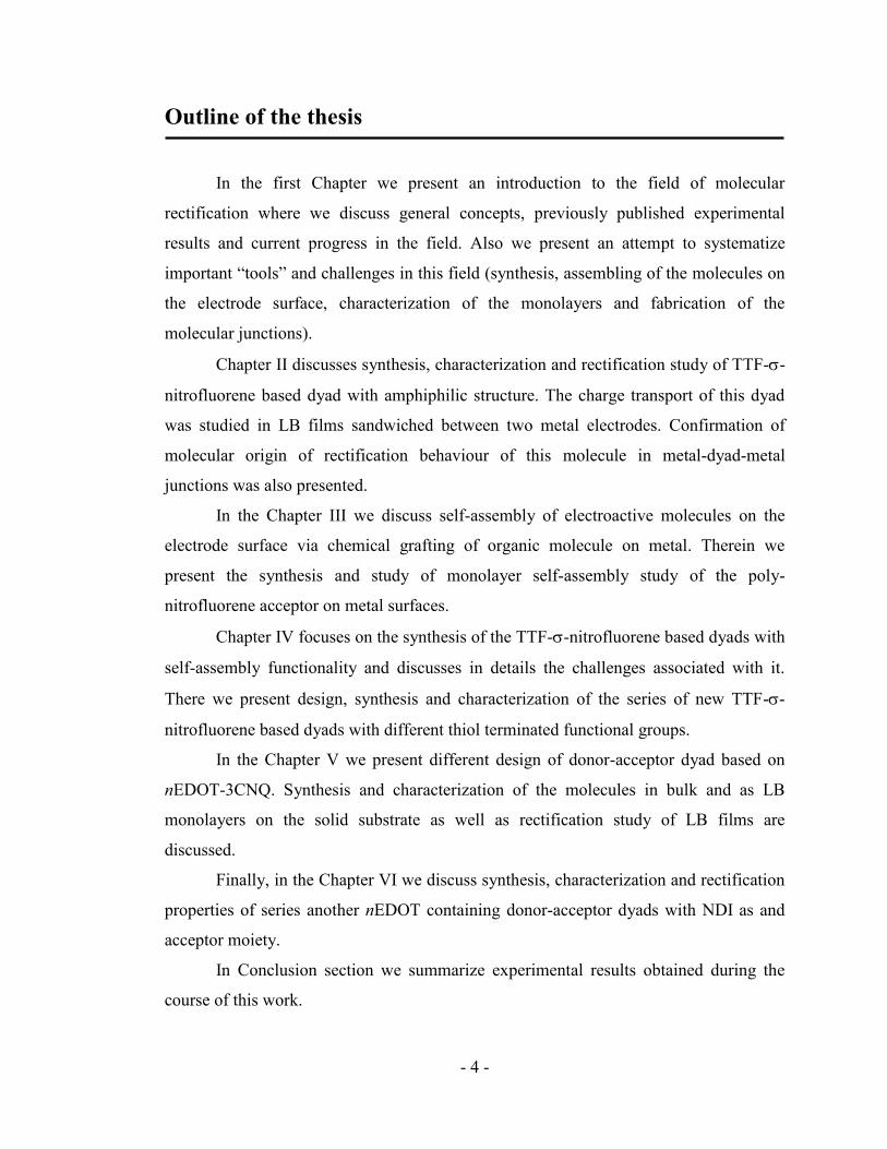
Figure 1.17: Process of the growth of the SAMs: a) immersion of the substrate into the
dilute solution of the molecules; b) initiation of the self-assembly process; c) formation
of the densely-packed monolayer.
For monolayers containing closely packed alkanethiols, the spacing of the alkane
chains is 4.97 Å as determined by low-energy electron diffraction [117]. This spacing is
almost three times larger than the van der Waals radius of sulfur (1.85 Å) suggesting
minimal S-S interactions [118]. This distance is also greater than the distance of closest
approach of the alkyl chains (4.24 Å). This difference in spacing causes the axis of the
alkyl chains to tilt by 30° from the surface normal [97, 118-120]. The tilt angle is
virtually independent (within a few degrees) of the functionality of the head group, as
long as it is not larger than the spacing between the alkyl chains [118].
Numerous theoretical studies suggest that the reaction of the thiol with the gold
surface proceeds through as oxidative addition of the S-H bond to the Au, followed by
elimination of the hydrogen. Such chemical bonding corresponds to energy of ~40
kcal/mol [93]. Also the monolayer packs tightly due to van der Waals interactions (~1
kcal/mol per each methylene group in the chain [121]), thereby reducing its own free
energy [116, 122]. All this makes the SAMs stable in a wide range of temperature,
solvents and potentials. The thermal stability of alkanethiolate SAMs has been studied in
a number of papers. It has been reported that loss of sulfur from hexadecanethiolate
monolayer on gold occurred over the range of 170-230°C. A temperature-programmed
desorption of methanethiolate SAMs on gold reported a desorption maximum at 220°C
[123-124].
Page 50
- 39 -
1.4 Characterization of organic monolayers
Analysis of the surface composition, structure and its physical properties as well
as alignment of molecules in monolayers is important for understanding their electrical
behaviour in molecular junctions. In contrast to inorganic thin films or organic
compounds in bulk, molecular monolayers are extremely fragile and soft, and thus
require non-destructive analytical tools. Among them, many spectroscopic methods such
as attenuated total reflection FT-IR, surface-enhanced infrared absorption, X-ray
photoelectron spectroscopy (XPS), near-edge X-ray absorption fine structure
spectroscopy (NEXAFS), time-of-flight secondary ion mass spectrometry (TOF-SIMS)
and surface plasmon resonance (SPR) have been widely used to obtain information
about thickness, structural disorder, chemical composition and presence of impurities in
the molecular films. Contact angle measurements provide additional information about
the changes in surface wettability after its modification. Finally, electrochemical
characterization of the SAMs on the electrode surface provides knowledge about the
conductivity of the film and the nature of the redox activity.
1.4.1 Ellipsometry
Measuring the thickness of the film can provide important information about the
geometric structure (monolayer or multilayer) of the film and alignment and order of the
molecules within the monolayer. A common technique to determine the thickness of the
films, for ~1 nm to several microns, is ellipsometry. Figure 1.18 shows the principle of
the ellipsometric measurement.
Ellipsometry was extensively used to study the physical and optical properties of
both LB films and SAMs. In addition to theoretical elaboration of ellipsometric models
for studying thin films, [125-127] a great deal of experimental research has also been
done in this field. For example, Porter et al. found by ellipsometry a noticeable decrease
of the thickness for monolayers formed from alkanethiols with chains shorter than 8
methylene groups. These results were interpreted as a decrease in monolayer order for
molecules with shorter chains [97]. The alignment of molecules in LB films can also be
Page 51
- 40 -
studied by ellipsometry measurements [128]. Ellipsometry was shown to be very useful
for real-time in situ monitoring of the films formation and growth [129-131].
Figure 1.18: Schematic presentation of the ellipsometry setup.
1.4.2 Contact angle
The quality of the monolayer can often be estimated from wetting properties of
the surface. Wetting is the ability of a liquid to maintain contact with a solid surface,
resulting from intermolecular interactions when the two are brought together. The
degree of wetting (wettability) is determined by the force balance between the adhesive
and cohesive forces. The free energy of the surface will affect the free energy of the
droplet of water on that surface and, as a result, will determine the shape of the droplet.
Figure 1.19: Measurement of contact angle
Page 52
- 41 -
The contact angle (θ), as seen in Figure 1.19, is the angle at which the liquid-
vapour interface meets the solid-liquid interface. The contact angle is determined by the
resultant between adhesive and cohesive forces and provides an inverse measure of
wettability. If the liquid is very strongly attracted to the solid surface (for example
oxidized surfaces that can form hydrogen bonding with water) the droplet will
completely spread out on the solid surface and the contact angle will be close to 0°. Less
hydrophilic solids will have higher contact angle. On many highly hydrophilic surfaces,
water droplets will exhibit contact angles of 0° to 30° (e.g. pure metals). If the solid
surface is hydrophobic, the contact angle will be larger than 90°. On highly hydrophobic
surfaces the surfaces have a water contact angles as high as ~120° on low energy
materials (e.g. polymers, such as PVC and Teflon). However some materials with highly
rough surface may have water contact angle greater than 150°. These are called super-
hydrophobic surfaces [132-133].
The relations between the contact angle and properties of the thin films and
monolayers have been extensively studied. For example, Bain et al. attributed the
difference in contact angles of mercaptocarboxylic acids with different alkyl chain
lengths to the order/disorder factor in monolayers (longer chain acids form more ordered
monolayers) [134]. The same group has also studied the effect of various terminal
groups (CH3, OH, etc.), chain length and other parameters on wettability of the thiol-
based monolayers [91, 119].
A good estimate of the SAMs uniformity can be obtained by monitoring the
difference between the advancing and receding contact angles. This difference, called
the contact angle hysteresis, is a measure of the physical and chemical nonuniformity of
the surface [135].
1.4.3 Reflection-absorption and ATR infrared spectroscopy
IR spectroscopy is one of the most surface-sensitive, non-destructive methods for
the characterization of chemical composition, structure, and orientation of molecules at
surfaces with monolayer resolution. The properties of the molecules in thin films
absorbed on a surface can be very different from those in bulk and these differences can
Page 53
- 42 -
be characterized by IR spectroscopy. For the analysis of metal surfaces, the most
successfully used method is reflection-absorption infrared spectroscopy (RAIRS or
Grazing-angle IR). In addition to the techniques used for metals, semiconductors and
insulator surfaces are widely probed by attenuated internal reflections (ATR) IR
spectroscopy. Other infra-red techniques, such as photoacoustic spectroscopy (see for
example [136]) and photothermal displacement spectroscopy [137], are also infrequently
employed to test the absorbance of different materials on the surface. General
considerations about using one method or another usually depend on different factors
and are based on the relative sensitivity of the method to studying the monolayer and
surface.
Francis and Ellison first recognized that a large incident angle is necessary to
enhance sensitivity [138] and the pioneering work on the RAIRS for SAMs was done by
Allara and Swalen [139]. The first studies of alkyl thiols on gold surfaces showed that
both the width and the position of the CH2 stretching vibrations are sensitive to the
structure of the film.
The RAIRS method requires IR radiation to be incident at a particular grazing
angle to a metal surface, on which an organic layer has been deposited (Fig. 1.20).
Incident perpendicularly-polarized radiation undergoes a phase shift of 180 on
reflection from the metal surface and so the electric field components of the incident and
reflected radiation cancel at the metal/thin film interface. In contrast, the incident and
reflected components of parallel-polarized IR radiation differ by only about 90 at
grazing incidence. This is the origin of the surface selection rule, which results in the
very useful ability to distinguish vibrations that possess a transition dipole moment with
a large component perpendicular to the surface [140].
Page 54
- 43 -
Figure 1.20: Schematic diagram of the grazing-angle FTIR spectroscopy from a thin
film-covered surface.
In attenuated total reflection spectroscopy (ATR), a beam of infrared light is
passed through the ATR crystal in such a way that it reflects off the internal surface.
Changing the angle of incidence may vary the number of reflections. The total internal
reflection occurs when the light strikes the medium boundary at the angle larger than a
particular critical angle with respect to the surface normal. This internal reflectance
creates an evanescent wave that extends beyond the surface of the crystal into the
sample held in contact with the crystal (Fig. 1.21). The penetration depth into the sample
is typically between 0.5 and 2 micrometers, with the exact value being determined by
the wavelength of light, the angle of incidence and the type of ATR crystal [141].
Figure 1.21: Formation of the evanescent wave at the internal reflection surface.
Page 55
- 44 -
A large variety of molecules and monolayers have been studied using grazing
angle and ATR infrared spectroscopy For the purposes of this thesis, it is not possible to
completely review all the examples of IR methods used to quantitatively study
monolayers structures and the orientation of molecules in monolayer assemblies. We
will cite only those most related to the work in this thesis. The application of IR
spectroscopy to study the orientation of molecules at the surface has been well
developed [139, 142-145]. The most studied by IR spectroscopy are monolayers of alkyl
thiols on gold surfaces [146], fatty acids on metal oxide surfaces [97, 103, 147-149] and
LB films [150-152]. For these monolayers the specific spectral features of C-H
vibrations can be correlated with order/disorder of the film. In principle, the relative
intensity of the peaks and their position are associated with the orientation of the dipole
moment of the vibration modes for C-H bonds and, accordingly, provide information
about the molecular orientation on the surface. Important information can be obtained
from the difference between the IR spectra of the bulk and the monolayers. The
frequencies of the CH2 stretching are very sensitive to the conformational ordering of the
alkyl chain within the monolayer. The frequency shifts are not large (5-7 cm-1
);
nevertheless, it was found that when alkyl chains in the monolayer are all in trans
conformation and highly ordered, the absorption bands of asymmetric and symmetric
methylene vibrations appear at 2918 and 2850 cm-1
, respectively. However, with the
presence of gauche conformation, the bands shift bathochromically to 2926 and 2856
cm-1
, as studied for both LB films and SAMs [149, 153]. The bandwidths of the CH2
vibrational modes were also found to be dependent on the degree of mobility and
flexibility of the molecules within the monolayer and it increase with decreasing order.
This parameter can also be used to determine the structure of the films [154-156]. The
relative intensities of the stretching vibration when using polarized light provide
information about the tilt angle of the bond with respect to the surface normal [143,
157].
Page 56
- 45 -
1.4.5 Electrochemical characterization of SAMs
Cyclic voltammetry (CV) is a powerful electrochemical tool to study the stability
of the films and electron-transfer in redox active species present on the surface of an
electrode. CV has also been used to investigate monolayer structure and packing of
molecules adsorbed on the electrode [97, 158]. The presence of defects and pinholes in
the monolayers can also be verified by electrochemistry. As the close-packed SAMs on
the electrode block diffusion of species to the electrode surface, evidence for pinholes or
defects can be obtained by analysing the blocking behaviour of additional layers
specifically at the bare metal surface [159-161].
The nature of the electrode surface is a critical factor in all of the electrochemical
processes that take place. When the electrode surface is coated with a layer of organic
molecules one can expect the electrochemical processes to be significantly affected.
Specifically, the film present on the electrode surface can retard or completely block the
electron transfer by increasing the separation between the electrode surface and redox-
active molecules. However, if the thickness of this film is small (for example a self-
assembled monolayer on the gold electrode) the electrons can still tunnel through it.
Also, if the electroactive centers are all close to the electrode surface, then diffusion
should not have any influence in the process. Accordingly, one should expect the
oxidation and reduction peaks be at the same potential for electrochemically reversible
redox reactions (Fig. 1.22) [162]. However, in some cases the separation between the
two potentials can still be observed. Often, this can be explained by slow electron
transfer at the electrode surface.
The most common example of electroactive SAM is formed by ferrocene
derivatives with thiol-terminated alkyl tail. Adsorption kinetics [163] and exchange of
the thiols between the SAM and solution [164-165] can be studied if one of the
components is electrochemically active. The relationship between the film structure and
CV response was studied in experiments with mixed SAMs composed of thiol-
terminated ferrocene and different alkyl thiols. For example, the location of the
ferrocene head-groups in the SAM and on the surface of the SAM causes the existence
of multiple formal potentials which results in broadening of the peaks [164].
Page 57
- 46 -
Experiments with varying the alkyl chain length of the thiols, leading to the ferrocene
group ―buried‖ in the SAM, confirm the broadening of the peaks and shift to more
positive potentials [166-168].
Figure 1.22: Cyclic voltammogram of an Au electrode coated with a mixed monolayer
containing thiol terminated ferrocene [169].
For an electroactive species adsorbed on the surface of an electrode, cyclic
voltammetry can be used to determine the surface density. This is done by integration of
the area under the oxidative curve to quantify the total charge passed in the
electrochemical process, and is expressed by the following equation:
(1.3)
where Γ is the surface coverage in mole/cm2, Q is the charge passed to
oxidize/reduce the molecule, n is the number of electrons in the electron-transfer
process, F is Faraday’s constant, and A is the area of the electrode.
Stability of the SAMs is an important factor that contributes to the application of
the molecules in electronic devices. By analyzing the redox response during the multiple
CVs scanning, a quantitative characterization of the SAM stability can be obtained [170-
172].
Page 58
- 47 -
1.5. Fabrication of molecular junctions
To study the rectification of a single molecule one would need to attach two
metallic probes on both sides of the molecule and examine the conductance of the
junction by studying its I-V characteristic at forward and reverse bias. However,
addressing an individual molecule presents a series of technical difficulties. Only a
recent progress in nanostructure characterization (STM/AFM) and nanofabrication tools
made such experiments possible.
The most simple and common approach for fabricating the metal-molecule-metal
junctions is based on ordered structures assembled on the first electrode, on which the
second electrode is then fabricated or positioned. This approach uses a metal electrode
supporting a SAM or LB film as one contact and a second contact generated on top of
the organic surface by different methods such as:
depositing a metal film by vacuum deposition or electrodeposition [44, 173];
transferring a metal film by flotation or nanocontact printing [174];
positioning a conducting probe (STM [175] or conducting AFM [176];
making a contact with a liquid metal contact (mercury) [177];
using conductive polymer mixtures (PEDOT:PSS) as a barrier between metals and
organic monolayer [178].
A second approach involves fabrication of junctions by positioning the
molecules across the nano-gap between the electrodes. The gap can be fabricated by
breaking a single wire mechanically or electrochemically [179] or by narrowing a gap
by electrodeposition of metal [173].
Each type of junction has certain advantages and limitations. In this work we
will discuss in detail three of these methods, thermal vacuum evaporation of the top
metal electrode, mercury-drop junctions and scanning probe microscopy, as the most
accessible tools that a synthetic chemist can use to study the electronic properties of the
molecules.
Page 59
- 48 -
1.5.1 Vacuum deposition of the metal on top of the organic layer
The preparation of metal thin films by vacuum deposition is one of the first
techniques used for metallization of organic surfaces. The nature of the contact between
organic molecules and metals depends strongly on chemical reactions that can occur
between an evaporated metal and the terminating group of a molecule. Evaporated metal
atoms may also penetrate through the organic monolayer and short out the device or
even create meta-stable filaments that switch the conductance on and off during the
measurements [180]. Many studies of the thin films have shown that metals such as Ti
and Cr are highly reactive toward organic functional groups, while Au and Ag are
mainly inert [180]. The degree of penetration of the metal atoms increases with
decreasing reactivity, which makes Ti a contact metal of choice for many studies [179,
181]. Titanium is a unique metal for an evaporated top electrode. Due to its high
reactivity, it immediately cleaves terminal C–H bonds forming a thin titanium carbide
layer on the surface of the monolayer that prevents further penetration of the Ti atoms
inside the film [182]. In the case of less reactive metals, during the evaporation on top of
the organic film, a sample holder should be cooled by liquid nitrogen. This is usually
sufficient for Al deposition [44]. For gold deposition, the so-called ―cold gold‖ method
was developed to prevent organic film damage. In this technique of deposition the Au
atoms are forced to undergo multiple scattering before they reach the substrate by adding
Ar gas to the evaporation chamber and by positioning the substrate on the opposite side
of the holder (away from the crucible) [28, 38, 47].
An interesting modification of this technique was developed by Reed and co-
workers [183]. In this method a pore in the SiN with a 30–50 nm aperture was fabricated
using combination of different microfabrication methods (Fig. 1.23). The pore was then
filled with gold by thermal evaporation and the whole device was immersed in a solution
of the studied molecule (4-thioacetylbiphenyl) to form a SAM. After deposition, the
second electrode was formed by evaporating gold onto the sample, at 77 K to minimize
damage to the SAM [184]. The significant disadvantage of this method is that once the
structure is sealed by the evaporated electrodes, it is impossible to study the structure,
order or orientation of the SAM even before the top electrode is evaporated in place.
Page 60
- 49 -
Figure 1.23: ―Nanopore‖ junction [183].
1.5.2 Liquid metals drop junctions
Extraction of reliable data out of molecular junctions requires statistical analysis of a
large number of measurements. This creates a demand for a simple and soft method to
form a mechanical contact to an organic film supported on electrode surface (such as
SAM on the gold). Mercury has been used for a long time in the formation of tunneling
junctions. Mann and Kuhn [185] used mercury to form various metal/LB film/metal
tunneling junctions. Later, the groups of Whitesides and Rampi [113-115] and Majda
[186-187] independently developed the method to create metal/SAM//SAM/metal
junctions using mercury drop as one of the electrodes or both electrodes. Thiol-
terminated molecules can form SAMs on the mercury surface, similarly to gold.
Bringing the modified mercury electrode into contact with the studied SAM on the
second electrode results in formation of metal-SAM-SAM-metal junctions (Fig.1.24).
Such junctions are fast and easy to make, allow for different combinations of SAMs and
metals to be used, and provide control over the size of the contact. One difference
compared to other molecular junction methods is a new SAM-SAM interface. The
organic monolayer on the top mercury electrode is necessary for protection of two metal
Page 61
- 50 -
electrodes from direct contact, which would lead to amalgam formation. The electron
transport in these junctions can be monitored as a function of the interaction between
these two SAMs. It was found that covalent, hydrogen bond and van-der-Waals
interactions could change the conductivity of the junctions by more than four orders of
magnitude [188]. Similar systems with only one SAM (e.g., contact made between bare
Hg electrode and SAM-modified gold substrate) are usually not stable and easily form
an amalgam due to presence of defects in the organic layer. However, use of mercury-
SAM-semiconductor (ex. Si substrate) interface avoids this problem [189]. The
disadvantages of mercury drop based junctions are in significant influence of the surface
topography and the structure of the SAMs on reproducibility of the measurements [190].
Recently, Whitesides and Nijhuis successfully used another liquid electrode
(eutectic alloy of gallium and indium, Fig. 1.8). The Ga2O3/EGaIn electrode is much less
likely able to form short-circuits with the bottom electrode and thus eliminates the
necessity of using an alkylthiol protective layer on the second electrode (like in case of
mercury) [191] and significantly increases the yield of successful measurements [192].
Figure 1.24: Mercury drop junction technique for measuring electronic properties of the
molecules [114]).
Page 62
- 51 -
1.5.4 Electron Transfer in Metal-Molecule-Metal Junctions
Above we described the methods and techniques to build the systems for
studying the molecular conductivity. Interpreting the results though, require
understanding of the processes by which an electron moves across the metal-molecule-
metal junction, and is generally very complicated. Several important components of the
system determine how electrons traverse metal–molecule–metal junctions [193]:
energy and position of the molecular orbitals;
the type of bonding in the metal–molecule junctions (molecule-metal
interface ) which determine the interaction;
energy alignment of molecular orbital levels with the Fermi levels in the
metal.
The basic mechanism for electron transport in all types of systems generally
involves electron tunnelling – a process of crossing a finite potential barrier by a
wavelike particle. Its probability depends on the barrier width and availability of the
unoccupied states (LUMO or conduction band) on the other side of the barrier. The
tunnelling current shows an exponential dependence on the length of the barrier
(molecule):
(1.4)
where β is a structure-dependent tunnelling attenuation factor, l is a width of the
barrier (length of the molecule).
The electronic structure of the molecule plays a significant role in the electrical
behaviour of molecular devices. If the molecular orbitals are fully delocalized along the
entire molecule then the electron can traverse the molecule in a resonance process and
the molecular junctions will exhibit high conductivity, as for example the π-conjugated
oligo(phenylene ethynylene) [173, 194]. In contrast, if the molecular orbitals are
localized on a specific part of the molecule, then the electron will have to tunnel through
the non-conductive part of the system. In most cases, the HOMO and LUMO orbitals of
the molecule are not aligned relative to the electrode Fermi levels. Applying an external
Page 63
- 52 -
bias shifts the Fermi levels of the metal electrodes: the negative voltage will raise the
Fermi level and positive voltage will lower it. The electronic structure of molecules also
substantially changes upon making the electrical contact with metal electrodes and as a
function of applied bias voltage. Generally, this process lowers the potential barrier
between the electrode and the molecular orbitals and makes tunnelling possible.
Another important characteristic of the junction is the nature of the contact
between the molecule (anchor functionality) and the electrode. In the ideal case, a low-
barrier ohmic contact between the metal and organic molecules will allow to study the
―pure‖ molecular electronic behaviour. However in real junctions it is not the case and
most interfaces used to study the conductivity of the molecules and molecular
assemblies have significant barriers for the electrons or holes injection, which may even
dominate the whole junction behaviour. The contact, actually, controls the energy and
mixing between molecular orbitals and the electronic states of the metals [195]. It was
demonstrated that a conjugated molecular wire, chemically bound to one gold electrode
by the thiol linker and in only physically contact with the second gold electrode shows
current rectification [196]. The effect of the different contacts was shown in series of
experiments by keeping the contact on one end of the molecule constant (S-Au) and
varying the contacts on the other end (Fig. 1.25) [194, 196]. Since one end of the
junctions is always the Au-S the observed rectification ratio can be related to the amount
of electronic coupling between the molecule and the metal at the second contact. The
more effective interaction between molecule and the metal leads to the symmetric I-V
characteristics. However, poor orbitals mixing at metal-molecule interface results in
strong current rectification. Thus, it shows the importance of metal/molecule contact in
charge transport of the entire junction.
Page 64
- 53 -
Figure 1.25: Rectification ratio as a function of applied bias for several
Au/molecule/Au junctions with different contacts at two terminals [194].
The complete picture of the charge transport across the junctions is complicated
and depends on many different factors. In addition to the search for the low-barrier
contacts between electrode and the molecule we should consider that the alignment may
also determine the charge transport barrier. Furthermore, the position of HOMO and
LUMO energies varies with the applied electrical field [197-198]. Even more
complication arises in multicomponent molecular junctions (ex. Metal-SAM/SAM-
Metal). The interaction between the molecules in such junctions may result in
electrostatic barrier, orbitals mixing and energy splitting [199]. Finally, simple defects in
the junctions sometimes may mislead the interpretation of the junction behaviour.
Page 65
- 54 -
Conclusions
The properties of the molecules play a significant role in the behaviour of the
molecular devices. A careful selection of the components and design of future molecular
rectifiers is therefore very important for successful projects. Such design rules include a
proper choice of the Donor and Acceptor moieties that will result in a small and
adjustable HOMO-LUMO gap of the dyad and position of molecular orbitals vs. Fermi
levels of the electrodes. The linker between the electroactive moieties should provide a
separation of the molecular orbitals of the donor and the acceptor. Finally, the molecular
blueprint should include a design of appropriate functional groups which will assist in
the assembly of the molecules between two electrodes.
The nature of the metal-molecule junction can have substantial influence on the
performance of the device. One of the important issues in regards to analysis of the
results are the difficulties associated with understanding the chemical nature and
structure of the junctions and contacts that are being measured. Use of wide range of
current analytical techniques can provide exhaustive information about chemical
composition of the bulk materials and thin films, alignment of the molecules within the
monolayer and properties. There are also many approaches to fabricate the electrode-
molecule-electrode junctions, such as vapour deposition of the top electrode on the
monolayer and liquid electrode junctions that allow measurement of conductivity of a
small number of molecules.
Although molecular rectification was shown and confirmed in numerous papers
for different molecular systems, there are still many open questions and challenges that
retain the interest of the researchers in this field. Particularly, the molecular rectifier with
the structure of the original Aviram-Ratner model has not been tested experimentally
yet. Several donor-acceptor dyads with low HOMO-LUMO gap were previously
reported in literature; however, their rectification properties were not demonstrated.
Creating such molecular systems with very strong electronic asymmetry could be a
potential way to eliminate the influence of the external factors (contacts, defects, etc.) on
the rectification behaviour of the molecular junctions.
Page 66
- 55 -
Chapter II. The first studies of a tetrathiafulvalene-σ-acceptor
molecular rectifier
(Part of this Chapter was adapted with permission from: G. Ho, J. Heath, M.
Kondratenko, D. F. Perepichka, K. Arseneault, M. Pezolet, M. R. Bryce, The first
studies of a tetrathiafulvalene–σ–acceptor molecular rectifier, Chem. Eur. J. 2005, 11,
2914–2922. Copyrights 2005 Wiley-VCH Verlag GmbH&Co. KGaA, Weinheim)
Introduction
Shortly after discovery of metallic conductivity in the purely organic donor–
acceptor (D–A) complex of TTF and TCNQ [200], Aviram and Ratner proposed the
concept of a molecular rectifier [25]. Their work was based on theoretical study of a
covalent donor-bridge-acceptor (D--A) molecule, such as TTF--TCNQ (2.1) in which
is a saturated aliphatic linker.
Since then, numerous attempts of the synthesis of molecules with a small
HOMO-LUMO gap have been done [28, 201-202]. Still, the design and synthesis of
such systems presents considerable challenges. And since, the hypothetical TTF--
TCNQ molecule 2.1 with a HOMO-LUMO gap of 0.3 eV was never synthesized, a
special synthetic interest exists for coupling together these moieties.
The closest analogue to the Aviram-Ratner rectifier 2.1, a compound 2.2 was
successfully synthesised in analytically pure form from TTF lithium alcoholate and a
TCNQ acid chloride at –100 C; this favoured covalent coupling via ester formation
over electron-transfer processes [72]. The molecule has two reversible oxidations and
two reversible reductions in cyclic voltammetry (CV) experiments that are characteristic
Page 67
- 56 -
of the TTF and TCNQ moieties, respectively, and the difference between the E0
1ox and
E0
1red values suggests an HLG of only 0.17 eV. However, such an extremely low HLG
leads to an easy electron transfer in the solution at thermal excitation. Also, ―head-to-
tail‖ geometry of the molecule limits the use of the molecule for rectification
measurements. The coupling of different acceptors, fluorene derivatives
(dicyanomethylene derivative of tetranitrofluorene has very strong electron affinity
[203], very similar to TCNQ), with TTF-CH2OH was first attempted by Perepichka et
al. [69, 204]. Following standard conditions for pyridine catalyzed ester formation they
successfully synthesised compounds 2.3. Important feature of the nitrofluorene as an
acceptor is that a condensation of it with malononitrile takes place under mild
conditions, which results in facile conversion of a moderate acceptor into a strong one,
thus, reducing probability of the charge transfer salt formation during the coupling
reaction [68]. The flexible linker in the molecule 2.3 is long enough to allow an
unwanted head-to-tail conformation, which leads to a formation of the intramolecular
charge-transfer complex. Using an acceptor derivative like fluorene-4-carbonyl chloride
would provide a shorter bridge with donor moiety and, thus, prevent formation of the
intramolecular complex [204]. TTF-fluorene dyad 2.4 was synthesized by coupling
fluorene acid chloride with the lithium alkoxide derivative of TTF-CH2OH at –100 C.
Increased reactivity of donor synthon and a lower reaction temperature in this coupling
reaction minimize charge-transfer complex formation. A very low HOMO–LUMO gap
of approximately 0.3 eV was found for molecule 2.4 [69] which is close to the value of
the original A-R molecule (2.1). Thus, the dyad 2.4 appears as a suitable candidate for
testing as a molecular rectifier.
Page 68
- 57 -
Herein we present an improved synthesis of TTF--nitrofluorene dyad 2.4, its
characterization by spectroscopic and electrochemical methods, preparation of its
Langmuir-Blodgett monolayer on solid substrates and its analysis by ATR IR
spectroscopy. Finally, we discuss our results on the rectification study of the dyad in
Si/LB-film/Ti and Au/LB-film//C16S-Hg junctions.
2.1. “Amphiphilic design”
The general design of the D–bridge-A dyad 2.4 includes a strong electron donor
(TTF) and a strong electron acceptor (nitrofluorene) separated by a saturated bridge, and
an amphiphilic structure enabling fabrication of a Langmuir–Blodgett films [204]. Such
design makes this molecule a suitable candidate for molecular electronic devices,
particularly in the frame of the original Aviram–Ratner rectification concept. A 4,5-
dipentyl-4’-methyl-TTF 2.5 was considered to be an appropriate TTF building block as
alkyl substitution is known to lower significantly the oxidation potential of TTF (i.e.
raise the HOMO). Pentyl chains would also enhance solubility in organic solvents and,
moreover, serve as hydrophobic elements in the amphiphilic structure of the dyad. The
linker between donor and acceptor in 2.4 is short enough (three atoms) to prevent an
intramolecular head-to-tail interaction between the donor and acceptor fragments of the
dyad.
2.2. Synthesis of TTF--fluorene dyads
Modification of the donor moiety was done following literature procedure [204]
and is presented in Scheme 2.1.
Page 69
- 58 -
Scheme 2.1: Synthesis of TTF-donor synthon.
Lithiation of the TTF derivative 2.5 [205] with LDA, followed by the reaction of
the lithium salt with N-methylformanilide afforded an aldehyde 2.6 in 66% yield. The
aldehyde was reduced with NaBH4 to give hydroxymethyl-TTF 2.7 in 88% yield.
The covalent linkage of the TTF fragment with fluorene acceptor was achieved
through the formation of an ester bond. The carbonyl group on the acceptor (fluorene)
component 2.8 was converted into fluorene-4-carbonyl chloride 2.9 as presented in
Scheme 2.2.
Scheme 2.2: Synthesis of acid chloride derivative of the acceptor synthon.
The dyad 2.11 was successfully synthesized in 78% yield by coupling 2.9 with
the lithium alkoxide derivative of 2.7 (Scheme 2.3) at –100 C, resulting in desired dyad
as a dark crystalline compound.
Page 70
- 59 -
Scheme 2.3: Coupling together donor and acceptor synthons. i) 2.7 + BuLi, THF, –
100C 20C, 1h, then + 2.9, –100C –15C, 3h, then –15C, 12h.
The acceptor ability of the fluorene moiety of 2.11 was increased by conversion
to the dicyanomethylene derivatives 2.4 (with 95% yield) by treatment with
malononitrile in DMF solution (Scheme 2.5).
Scheme 2.5: Conversion of the fluorenone 2.11 into dicyanomethylene derivative 2.4.
As the separation of the dyads 2.11 and 2.4 was difficult, the completion of the
conversion was achieved by large excess of the malononitrile. It was reported that under
these conditions a blue colour by-product can be obtained as a result of substitution of
the cyano group of 2.4 with a second molecule of malononitrile [204]. However, the
purification of the final molecule 2.4 from this by-product is easy by filtering the crude
mixture through silica gel layer.
2.3. Geometry and electronic structure of the dyad 2.4
To evaluate the molecular properties of the dyad 2.4, we calculated the geometry
and the orbital energies of a simplified molecule (lacking long alkyl substituents, Fig.
Page 71
- 60 -
2.1) by using density functional theory (DFT) at the B3LYP level, with a 6–31G(d) basis
set. This method is reliable for describing geometry and orbital energies of organic
molecules [206], and was successfully used to predict the HOMO–LUMO gap of a
related low-gap TTF--TCNQ dyad [72]. In accordance with previously reported
experimental observationsa [204], our calculations show no possibility for intramolecular
π-π complexation between the TTF and fluorene fragments. The conformational analysis
reveals the presence of several stable conformations, differing in energy by 1–2.5
kcal/mol.
Figure 2.1: The calculated [B3LYP/6–31G (d)] geometry of the dyad 2.4 in the
minimum energy conformation and the plot of HOMO (left) and LUMO (right) orbitals.
The calculated structural features of dyad 2.4 are similar to those previously
found by X-ray crystallographic analysis in the related compound 2.12 [204]; this
confirms the applicability of the chosen theoretical model. The variation of the
calculated HOMO–LUMO gap (0.30–0.35 eV) in different conformations is low, which
is in contrast to the dyads with a long linker [72]. The calculated HOMO-LUMO gap
is also very close to the experimentally observed electrochemical gap of compound 2.4
(0.29 V) obtained from cyclic voltammetry experiments. The HOMO–LUMO gap of 2.4
a Change in the solution UV-Vis absorbance as a function of concentration showed no linear trend and
almost no absorption at concentrations below 10–4
M, which clearly indicate that only the intermolecular
CT complex, is responsible for the long-wavelength absorption in dyad 2.4.
Page 72
- 61 -
fits almost exactly the original Aviram–Ratner model, in which the asymmetric I–V
curve was calculated assuming a 0.3 eV gap [25]. At the same time, the electronic state
of 2.4 (and, therefore, the rectification behaviour) in the tunnelling junction might be
difficult to predict. Although the ground state of individual molecules is neutral, the
electron transfer is very facile in these systems, as manifested by a relatively weak ESR
signal in solution. When an LB film of 2.4 is sandwiched between conducting
electrodes, the energy levels may be shifted significantly (due to intermolecular
interactions, electrode interface effects [207], and the applied electric field [35]). Such
shifts may even cause the gap to close, so that the zwitterionic biradical ground state of
2.4 (D+
--A–
) in the junction is a possibility.
2.4. Electrochemical characterization of the dyads in bulk
The cyclic voltammetry (CV) of the dyads 2.4 and 2.11 in CH2Cl2 presents clear
characteristic multiredox amphoteric behaviour (Figure 2.2) consisting of two reversible
single-electron oxidation waves corresponding to a radical cation and dication state of
the TTF moiety, and three reversible single-electron reductions of the fluorene fragment,
which afford a radical anion, dianion and radical trianion species:
The electrochemical potentials E0 of dyads 2.4 and 2.11 are given in Table 2.1,
together with data for donor synthons 2.5 – 2.7 to show the mutual influence of the TTF
and fluorene fragments.
As expected [208], the conversion of the keto group into the dicyanomethylene
group (2.112.4) results in a significant positive shift in the reduction potentials with
larger shifts being observed for first (E1red0=350 mV) and third (E3red
0=180 mV)
reduction peaks than for second ((E2red0=90 mV). For the TTF moiety, a decrease,
followed by increase in its donor ability was found upon the attachment of the electron
withdrawing CHO group (2.52.6) and conversion of it into electron releasing CH2OH
group (2.62.7).
Page 73
- 62 -
Table 2.1: Electrochemistry data (0.2 M Bu4NPF6 in CH2Cl2 vs. Fc/Fc+).
Compound E1ox0,V E2ox
0,V E1red
0,V E2red
0,V E3red
0,V E,eV
2.5a –0.15 0.32 – – – –
2.6a 0.00 0.52 – – – –
2.7a –0.23 0.24 – – – –
2.11 –0.10 0.40 –0.74 –1.02 –1.81 0.64
2.4 –0.10 0.41 –0.39 –0.93 –1.63 0.29
a) data from [204]
-1.5 -1.0 -0.5 0.0 0.5
2.4
2.11
E, volts (vs. Fc/Fc+
)
Figure 2.2: CV of dyads 2.4 and 2.12 measured in 0.2M Bu4NPF6 in CH2Cl2, vs.
Fc/Fc+.
As intramolecular charge-transfer interaction is not possible in the short-bridge
dyads 2.4 and 2.11, the donor ability of the TTF fragment in these compounds is not
perturbed (within 10 mV) by the ketone dicyanomethylene transformation. In
Page 74
- 63 -
accordance with the fact that this charge-transfer interaction should disappear with
reduction of the acceptor fragment to the radical anion, the presence of the TTF moiety
has no influence on the second and third reduction waves of the fluorene nuclei. The
difference between the oxidation and reduction potentials (E1ox0 – E1red
0) for compound
2.4 is as small as 290 mV, which represents one of the smallest solution HOMO –
LUMO gaps (the smallest reported was 0.17 eV for dyad 2.2 [205]) so far reached for
closed-shell organic compounds [209].
2.5. Preparation of monolayer of 2.4 on air-water interface
Deposition of the dyads on the electrode surface was performed by the
Langmuir-Blodgett technique. The initial procedure for the dyads 2.4 and 2.11 was
elaborated in the group of Prof. Heath. Following their method, LB films were prepared
by spreading a fresh solution (10-3
M) of the molecule 2.4 in chloroform on a dilute
aqueous buffer subphase (5×10⁻⁴
M Na2CO3/NaHCO3)a. After the solvent evaporated the
more polar dicyanomethylene fluorene fragments of 2.4 were presumably exposed to the
polar water phase, whereas the hydrophobic trialkyl-TTF moieties are stretched into the
air. The surface area was decreased with Teflon barriers, which created a change in
surface pressure that can be recorded by microbalances to yield an isotherm curve (Fig.
2.3). When the surface area was decreased below about 60 Å2 per molecule it resulted in
a sharp increase of the pressure. Further decrease up to an area about 30–35 Å2 per
molecule leads to monolayer collapse. The non-uniform shape of the isotherm with a
shoulder at about 50 Å2
per molecule may be explained by the conformational flexibility
of 2.4, resulting in multiple molecular orientations, each with their own characteristic
molecular area.
Brewster angle microscopy (BAM) of the Langmuir monolayers revealed small
spots (~100 microns in diameter) on the trough surface that appear immediately upon the
dropwise addition of a solution of 2.4 in CHCl3 to the surface (Figure 2.3). These islands
a For the control experiment with eicosanoic acid 3.045×10
-4M CdCl2/6.415×10
-5 NaOH aqueous
subphase was used.
Page 75
- 64 -
presumably correspond to molecular aggregates. The spots, however, spread out within
seconds to form a microscopically uniform surface. During the monolayer compression
with a speed of 2 cm2/min, the surface pressure was periodically held steady to check the
stability of the films. At a fixed pressure of 12 mN m-1
, the area dropped by less than
0.4% over 2 minutes, indicating a very stable monolayer. At higher pressures of 16 and
25 mN m-1
, there was an increased rate of monolayer relaxation (the trough area dropped
by 1.6 and 2.9 %, respectively, over a period 2 min). This is consistent with the
statement on conformational changes to 2.5 at the surface pressure 16-25 mN m-1
(or
surface area around 50 Å2).
Figure 2.3: Surface pressure isotherm of 2.4.
The few small spots (presumably dust particles), visible on the images (Fig. 2.4),
captured by the BAM remained steady on the surface for the entire two minutes,
indicating that the formed LB films were 2D solids. As stated above, the more polar
dicyanomethylene fluorene fragments of 2.4 were presumably exposed to the polar
water phase, whereas the hydrophobic trialkyl-TTF moieties are stretched into the air.
Page 76
- 65 -
Figure 2.4: BAM images of a) clean Langmuir trough; b) same, immediately after
dropwise addition of a solution of 2.4 in CHCl3; c) LB film of 2.4 at 12 mN m-1
; d) LB
film of 2.4 at 26 mN m-1
(the picture width is 480 mm).
2.6. Deposition of the monolayers on solid substrates
The LB films, compressed to the desired surface pressure were transferred onto
three different substrates required for characterization and study experiments.
LB films transferred onto hydrophilic (oxygen-terminated) polycrystalline n-
doped silicon substrates, and
freshly cleaned hydrophilica[210] gold substrates with contact angle 42±4 (for
rectification study);
freshly cleaned Ge ATR crystal (for infrared characterization).
Deposition on the Si wafer was done at three values of surface pressure (12, 16
and 25 mN m-1
). The transfer direction (slides start out dipped into the water before the
addition of the molecules, and are then lifted up through the LB film, ―Z-type‖)
necessarily resulted in the acceptor moiety being exposed to the slide surface. The
transfer on the gold slides was done in two opposite direction: 1) ―Z-type‖ as described
a We should note that gold surface has two surface energy stated: with bulk atomic properties
(unreconstructed) and reconstructed surface with shorter atomic lengths. This could be a possible
reason for duality of the gold surface presenting hydrophilic and hydrophobic behavior
respectively [210].
Page 77
- 66 -
above for the Si; and 2) ―X-type‖ resulting in the hydrophobic alkyl tails of the donor
being in contact with the gold surface.
Deposition was performed at constant rate (5 mm/min) with continuous control
of the surface pressure to insure uniformity of the deposited films. The transfer ratio for
the films deposited on the Ge crystal was always close to 1, while the transfer ratio for
the gold samples varied from sample to sample in the range from 0.4 to 1. This is
possible due to the non-uniformity of the slides’ surface. Normally one side on the slides
was covered with gold while other remains uncoated.
2.7. Spectroscopic characterization of LB monolayers
Infrared spectroscopy is very useful and highly sensitive technique to analyze the
nitrile stretching frequency depending on the charge accumulated on the molecule, and
can be utilized to monitor charge transfer interactions involving cyano-substituted
acceptors. For example, for TCNQ, CN = 2225 and 2180 cm-1
for the neutral and anion
radical species, respectively [211]. The CN of the dyad 2.4 (ca. 2203 cm-1
in KBr
pellets, fig 2.5) is substantially lower than that of similar fluorene acceptors without a
TTF moiety (2235 cm-1
) [204] and it could be attributed to significant charge transfer in
the solid state of 2.4. According to correlations of nitrile stretching frequencies with
degree of charge transfer (Z values) for TCNQ salts, Z-value for 2.4 equals
approximately 0.6 [211]. This value is very close to that of TTFTCNQ salt which
indicates the possibly of charge transfer in the solid state due to the π-π interaction
between the molecules.
To establish the preservation of chemical structure of 2.4 in transferred LB
monolayers, we have performed an infrared spectroscopic characterization of films
transferred (―Z-type‖) onto the surface of a Ge crystal by the attenuated total reflectance
(ATR) technique. We also investigated films transferred onto a gold substrate by
grazing-angle reflection–absorption infrared spectroscopy (RAIRS). Comparison with
the spectrum of bulk 2.4 (powdered in KBr, Figure 2.5), and of spectra of compounds
containing separate TTF and fluorene fragments, reveals the presence of all main
absorption peaks, suggesting the structural integrity of the transferred molecules (see
Page 78
- 67 -
Table 2.2 and Fig. 2.5). In spite of certain differences (such as much broader lines in the
LB film and somewhat different relative intensities) expected for different molecular
orientations and intermolecular interactions in the LB film and in the crystal, one can
clearly see the presence of a potentially vulnerable ester group (C=O, C–O), the
electron-acceptor fluorene fragment (cyano and nitro-groups as well as aromatic C=C
bonds), and the electron-donor trialkyl-TTF fragment (CH2, CH3).
3500 3000 2500 2000 1500 1000
KBr
wavenumber (cm-1
)
LB film
Figure 2.5: Infrared spectroscopy of the dyad 2.4 in bulk (KBr pellets) and LB film on
gold substrate.
The position of the significantly broadened CN band (2205 cm-1
, similar to that in the
bulk sample) is between those for a completely neutral (2225 cm-1
) and radical-anion
species (2180 cm-1
) [204], suggesting a partial charge transfer (either from the TTF
fragment or from the Ge surface). The lack of strong characteristic absorption bands of
the TTF core precludes a detailed analysis of this fragment, however, its presence is
observed from the strong aliphatic C–H stretching at ~2900 cm-1
. Also, the absence of a
sulfoxide bond (at ca. 970–990 cm-1
) [212], expected for S-oxidized species, suggests
Page 79
- 68 -
that no irreversible oxidative decomposition of this fragment took place (although one
cannot exclude a reversible formation of a TTF radical cation).
Table 2.2: Assignment of the major IR absorption peaks of 2.4 in LB film and in bulk,
their relative intensity (IX/INO2) as well as the dichroic ratio (RATR), order parameter
<P2> and average tilt angle () obtained from polarization experiments.
Peaks Bulk, cm–
1
LB, cm–1
IX /INO2
Bulk
IX /INO2
LB
RATR=As/Ap <P2> []
CHar 3106,
3093
3096 0.03 0.08
a CH3
a, CH2
s CH2
2956
2929
2859
2959
2928
2856
0.10
0.12
0.06
0.39
0.41
0.23
1.130.01
1.060.01
1.030.01
–0.010.03
–0.160.02
–0.210.03
55
61
65
CN 2203 2205 0.27 0.09
C=O 1735,
1718
1728 0.19 0.55 1.110.00 –0.060.00 57
C=Cring 1601,1579 1607 1591
1577
0.12 0.48 1.100.02 –0.050.03 57
a NO2 1534 1536 0.43 0.87 1.080.01 –0.120.02 60
C=C 1512 – 0.24
a CH3 1456 1457 0.19 0.45 1.070.01 –0.130.03 60
C-O 1422 – 0.48
1403 – 0.44
s CH3 1379 – 0.72
s NO2 1336 1341 1.00 1.00 1.090.01 –0.090.03 58
COC 1281 (1288) 0.53 0.27
COC 1255 (1262) 0.39 0.21
COC 1235 (1242) (1222) 0.23 0.19
a COC 1207 – 0.31
a COC 1185 (1190) 0.53 0.18
ra CH3 1151 1155 0.51 0.27
ra CH3 1102 (1102) 0.19 0.16
s COC 1089 (1081) 0.15 0.15
1075 (1058) 0.11 0.13
C-CH3 1034 (1025) 0.14 0.11
To study the structure of LB film of 2.4, an orientation analysis of the films
transferred on a Ge crystal was performed in collaboration with Prof. M. Pezolet (Fig.
2.6).
Page 80
- 69 -
Figure 2.6: Geometric representation of the determination of the molecules orientation
by ATR spectroscopy. S (transition moment) located at angle from c (molecular axis)
which is inclined at angle from Z (normal to the crystal surface); is an angle between
the transition moment S and Z [213].
ATR-FTIR spectra were thus recorded by using polarized infrared radiation, and
the dichroic ratio (RATR, eq. 2.1) was calculated from the absorbance of characteristic
bands for 2.4, obtained with the infrared radiation polarized parallel (Ap) and
perpendicular (As) to the plane of incidence.
2.1
The associated order parameters of the transition moment of a given vibration
with respect to the film normal <P2> can be calculated by using mean-square electric
field amplitudes (E2
x,y,z) obtained from the Harrick thin-film equations [214].
⟨ ⟩
2.2
The order parameter of the molecular axis, <P2(cos)>, can be calculated from
the order parameter of the transition moment, <P2> using the Legendre addition
theorem:
Page 81
- 70 -
⟨ ⟩ ⟨ ⟩
⟨ ⟩ ⟨ ⟩
2.3
where is the angle between the molecular axis and the normal to the ATR
crystal, and is the angle between the transition moment and the molecular axis.
Assuming that orientation distribution of the molecular axes is infinitely narrow,
the tilt angle can be calculated from the eq. 2.3, as:
√ ⟨ ⟩
2.4
The values of RATR, <P2> and the average angle γ between the transition
moment and the surface normal for the films transferred at the highest pressure (25
mNm-1
) are given in Table 2.2 for the major bands. It is important to remember here that
<P2> should be equal to zero for an isotropic sample (γ=54.9, the magic angle), and to
one and –0.5 for perfect orientation of the transition moments (S) parallel (γ =0) or
perpendicular (γ =90) to the surface normal, respectively [213, 215]. Table 2.2 shows
that the order parameter differs significantly from zero for several bands. For example, a
<P2> of about –0.2 is observed for the two methylene C-H stretching modes, revealing
that the CH2 groups are preferentially oriented in the plane of the LB film. Even though
the high wavenumber position of the maximum of the 2859 and 2929 cm-1
bands shows
that the alkyl chains are significantly disordered [149], as expected from the molecular
model of the films (Figure 2.7), the polarized ATR results indicate that they are
preferentially oriented along the surface normal with an average tilt angle of
approximately 30. On the other hand, the dichroic behaviour of the 2960 cm-1
band
indicates that the methyl groups are unoriented. The values for the angle of about 60
found for peaks corresponding to C=C and C=O double bonds and to the symmetric
stretching vibration of the NO2 groups at 1341 cm-1
(for which the transition moment is
bisector of the NO2 angle) shows unequivocally that the fluorene moiety is not lying flat
on the surface, although a more precise determination of its orientation is precluded by
the complexity of the structure (the presence of several similar bonds with different
orientations). It is worth noting that reproducibility of the orientation measurements
Page 82
- 71 -
(presented by the absolute error in Table 2.2 calculated for three different films), while
being quite acceptable for the films transferred at 25 mN m-1
was persistently very low
for the films transferred at lower pressures, as expected for poorly aligned low-density
films.
Figure 2.7: The top (left) and side (right) views of a model of an LB film of 2.4,
corresponding to a molecular area of 50 Å2 (the TTF-fluorene core is the DFT optimized
minimum energy conformer; the alkyl chains are added and optimized with the
molecular mechanics force field MM+; the molecules are manually placed in the closest
position, respecting van-der-Waals distances; the hydrogen atoms omitted for clarity).
2.8. Fabrication and electrical studies of n-Si/SiO2/2.4/Ti junction devices
Figure 2.8 shows energy levels for the studied junctions of the dyad 2.4.
According to the Aviram-Ratner proposal the preferred direction of the electron flow
should be from acceptor to donor (M2 to M1). The bias necessary to reach resonance
between work functions of the electrodes M2 and the LUMO of the acceptor is
significantly smaller than that necessary for the resonance between M1 and LUMO of
the donor. Notably, as the work function of the mercury electrode lies between energies
of HOMO and LUMO of the molecule and the difference between them is very small,
such system can be ideal for the future study of electronic properties of this dyad in Hg-
molecule-Hg junctions.
The molecular rectification of the dyad 2.4 initially was studied in n-Si/dyad/Ti
junctions in Prof. Heath’s group (Fig. 2.9). The monolayer of 2.4 was deposited on
degeneratively n-doped Si slide by LB technique (see section 2.6). Then, a second
Page 83
- 72 -
electrode (10 nm Ti followed by 4 m of Al) was deposited by evaporation on top of the
transferred monolayers to complete the fabrication of molecular tunnel junction devices.
Figure 2.8: Scheme of the molecular rectifier based on the dyad 2.4. The energy levels
of the molecule are calculated using DFT. Work functions for the electrodes are taken
from the literature.
The emerging picture of the deposition of metallic thin films, such as Ti and Au,
on molecular monolayers, is that the thickness and stoichiometry of the metallic film, as
well as the structure of the molecular monolayer, all play critical roles in determining the
extent to which the molecules are modified or damaged by the deposition [182, 216-
218]. Titanium is a unique metal for an evaporated top electrode. Due to its high
reactivity, it immediately cleaves terminal C–H bonds forming a thin titanium carbide
layer on the surface of the monolayer and may prevent further penetration of the Ti
atoms inside the film [182], as often observed for gold [217-220]. Preservation of the
molecular features buried inside the aliphatic chain protected monolayers has been
demonstrated by both X-ray photoelectron spectroscopy [216], and more recently by
RAIRS [182], which showed disappearance of only terminal CH3 vibrations, whereas all
Page 84
- 73 -
other infrared spectral features were unperturbed. At the same time, evaporation of a Ti
layer of >30 Å on self-assembled monolayers (SAMs) of predictably more reactive
conjugated compounds such as oligothiophenes [218] or oligo(phenylethynylene)s [217]
can result in complete destruction of the molecules. SAMs are also lower-density
molecular monolayers than compressed LB films, which would result in higher tilt
angles and exposure of larger part of the molecules to the incident Ti flux. During the
evaporation of the Ti we have tried to account for these facts by putting protecting alkyl
chains on the TTF moiety against the Ti and by using highly compressed LB films.
Figure 2.9: Scheme of the n-Si/2.4/Ti junction studied in Heath’s group.
We are also well aware of the criticism toward the claims of molecular
rectification from junctions based on oxidizable metal contacts. The titanium oxide
induced rectification was first pointed out by Ashwell et al. in 1980 [221] and a number
of rectifying Ti-based junctions for molecules lacking an evident ―diode‖ structure have
been reported to date [182, 222-223]. As was shown in these reports, such rectification
depends upon the level of oxidation at the molecule/Ti interface and can be controlled
by the level of vacuum used during the deposition of the Ti. Using a sufficiently high
quality e-beam deposition system (providing a vacuum of 5×10⁻⁷
Torr), we are able to
routinely control the vacuum, both to increase and to decrease the rectification. As
shown below in control experiments, under the correct Ti deposition conditions, and for
a degeneratively doped poly-Si bottom electrode, such rectification can be effectively
suppressed and experimentally separated from the molecular features.
Acceptor
Linker
Donor
e
Ti
Si
Page 85
- 74 -
The work functions of n-doped Si (–4.85 eV) and Ti (–4.33 eV) are similar to
each other (to minimize the rectification due to p-n junction), and also fit reasonably
well with the HOMO/LUMO levels of 2.5. As described below, any rectification arising
from the dissimilar poly-Si and Ti electrode materials or formation of an oxide layer
[221] can be experimentally separated from that which arises from the molecular
component.
Current-voltage curves obtained for these devices are depicted in Figure 2.10.
Notably, as the transfer pressure goes up, the magnitude of the current through the
junction decreases, implying an increasing distance between the top and bottom
electrodes as the monolayer aligns. The most dramatic effect, however, is that the
rectification ratio (RR) sharply increases with increased transfer pressure, from 1.5 for
56 Å2 molecule
–1 to 5 for 52 Å
2 molecule
–1 and 18 for 43 Å
2 molecule
–1. These
observations are in agreement with the alignment of molecules of 2.4 during
compression to form a well-packed monolayer with the D-A / surface angle being close
to normal.
Figure 2.10: The current–voltage curves obtained from the n-Si/2.4/Ti molecular tunnel
junction devices made from the three films indicated in the isotherm measurements.
Note that as the area per molecule decreases, the rectification ratio increases (by a factor
of 10), but the current decreases. Both the increased current rectification and the
decrease in current magnitude are indicative of an increased alignment of the molecular
monolayer.
-5
-4
-3
-2
-1
0
-1 -0.5 0 0.5 1
Applied Bias (V)
56 Å2
52 Å2 (x8)
43 Å2 (x35)
Cu
rre
nt
(mic
roA
mp
s)
0
20
40
60
10 30 50 70
Area per Molecule (Å2)
Su
rfac
e P
res
su
re(m
N·m
-2)
collapse
Transfer points
-5
-4
-3
-2
-1
0
-1 -0.5 0 0.5 1
Applied Bias (V)
56 Å2
52 Å2 (x8)
43 Å2 (x35)
Cu
rre
nt
(mic
roA
mp
s)
-5
-4
-3
-2
-1
0
-1 -0.5 0 0.5 1-1 -0.5 0 0.5 1
Applied Bias (V)
56 Å2
52 Å2 (x8)
43 Å2 (x35)
Cu
rre
nt
(mic
roA
mp
s)
0
20
40
60
10 30 50 70
Area per Molecule (Å2)
Su
rfac
e P
res
su
re(m
N·m
-2)
collapse
Transfer points
Page 86
- 75 -
Note that the only thing that is changing for the devices in Figure 2.10 is the area
per molecule, which translates into molecular orientation. Ellipsometry measurements of
a film transferred at 17 mN m–1
(~50 Å2 molecule
–1) suggested a thickness of 15-20 Å,
consistent with the formation of a monolayer of the most stable conformer (shown in
Figure 2.7). This conformer has a calculated thickness and molecular area of 21 Å and
50 Å2, respectively (Figure 2.7). Further compression at pressures above ~17 mN m
–1
would require conformational changes, and the film transferred at 26 mN m–1
most likely
has both fluorene and TTF fragments perpendicular to the surface. Thus, any current-
voltage asymmetry that might arise from the dissimilar electrodes, titanium oxide
formation, etc. is effectively a constant through this series of devices. Nevertheless, we
checked this conclusion by preparing similar devices containing an eicosanoic acid LB
monolayer in place of 2.4. In a number of experiments, these devices yielded a RR close
to 1, and never more than 1:2 – 1:3. Furthermore, no dependence of the rectification
ratio on the transfer pressure was found for eicosanoic acid, although the total current
was also observed to decrease for films transferred at increasing values of area/molecule.
Therefore, we assign the dominant contribution to the observed rectification (1:18) in the
monolayer of 2.4 as a molecular feature.
The maximum RR for a n-Si/2.4/Ti device is achieved at the relatively low
potential of 0.9 V. Above 1.0 V the rectification ratio decreases (Figure 2.11). This is
expected, because at sufficiently high applied bias, direct tunneling of charge carriers
between the two electrodes becomes an increasingly important (and eventually
dominant) mechanism of charge transport. In other words, at sufficiently high bias, the
specific details of the molecule become less important. The RR does not decrease (it
actually slightly increases) after 10 scans (up to 1.75 V). This is in contrast to D––A
systems in which the reorientation of highly polar molecules reduced the RR by a factor
of two every second scan [47, 55]. The direction of the observed rectification indicates
that the preferred electron current is from fluorene acceptor to TTF donor (from Si on
Ti).
Page 87
- 76 -
Figure 2.11: The dependence of the rectification ratio in the n-Si/2.4/Ti device on the
applied bias for a series of voltage cycles.
2.9. Fabrication and electrical studies of Au/2.4/Hg junction devices
The previously discussed rectification study of the dyad 2.4 in n-
Si/SiO2/molecule/Ti junctions [224] has few point of criticism. Briefly they are: (i) the
rectification is known for the junctions based on oxidizable metal contacts [28]; (ii) the
titanium oxide induced rectification was first pointed out by Ashwell et al. in 1980
[221], and a number of rectifying Ti-based junctions for molecules lacking an evident
―diode‖ structure have been reported to date [113-114, 182]; (iii) it was shown before
[113-114, 221], such rectification depends upon the level of oxidation at the molecule/Ti
interface and can be controlled by the level of vacuum used during the deposition of the
Ti. Although the evaporation of Ti was performed in high vacuum (<10-7
mbar), and the
pressure-dependence of RR shows the importance of molecular alignment, we cannot
completely rule out the possibility of small levels of oxidation, during the fabrication or
measurements of the dyad.
To further verify the molecular nature of the rectification behaviour displayed by
2.4, we performed an electrical measurement of the LB monolayer of 2.4 between
higher-work-function gold and mercury electrodes (5.3 eV and 4.49 eV, respectively).
Page 88
- 77 -
Such junctions are different from the n-Si/SiO2/molecule/Ti junctions because no oxides
are present on the metal surface (Au) and because the junctions themselves are relatively
simpler. The mercury electrode was covered with protecting alkyl thiol monolayer to
prevent direct contact of two metal surfaces through defects in the organic film (Fig.
2.12).
The LB film of 2.4 was transferred onto a gold substrate in the previously
described fashion (―Z-type‖, Au/fluorene--TTF interface, Fig. 2.12 a) [224], and the
electrical junction was established by micromanipulator-controlled contacting with a
hexadecanethiol-protected hanging mercury drop electrode. The dense defect-free Hg-
SC16H33 monolayer prevents electrical shorts (due to possible defects in the LB layer)
and formation of radical-ion salts on the mercury surface. Similar to Si/2.4/Ti devices,
the current-voltage response of the Au/2.4/C16H32S-Hg junction is highly asymmetric
(Fig. 2.13) with higher current at forward bias, which corresponds to the electron flow
from Hg to Au (i.e. from donor to acceptor), i.e. opposite to that predicted by AR model.
The unimolecular origin of the rectification was confirmed when the junction
consisted of the LB film deposited with opposite orientation: Au/TTF--fluorene/Hg
(Fig. 2.12b). Also, in a number of experiments performed, the devices containing an
eicosanoic acid LB monolayer in place of 2.4 yielded a RR of approximately 1.5–2, and
never more than 3. The more important fact is that the direction of the electrons flow has
changed to the opposite direction (from Au to Hg, at forward bias). This confirms that
the direction of the current flow strongly depends on the molecular orientation within the
LB film. The difference in the rectification direction for Si/Ti and Au/Hg (AD and
DA, respectively) could lie in the extremely low HOMO–LUMO gap of 2.4, which in
specific junction devices may change the ground state from a neutral TTF-σ-fluorene to
a zwitterionic TTF+
--Fluorene– (in which the TTF
+ becomes an acceptor and
Fluorene–
becomes a donor). Whatever the case, the results do highlight the important
role that the electrodes play in determining the current–voltage response of a molecular
electronic device. Although the exact mechanism of the different rectification directions
in these two studied junctions is certainly disputable, we believe that the molecular
Page 89
- 78 -
origin of such behaviour is adequately proved by the above molecular reorientation and
alignment studies as well as control experiments with eicosanoic acid.
Figure 2.12: Mercury drop junction of the dyad 2.4 a) junction with ―Z-type‖ deposited
LB monolayer on gold substrate; b) junction with ―X-type‖ deposited LB film; c) photo
of the mercury-drop junction device.
Page 90
- 79 -
Figure 2.13: I–V characteristics of Au/2.4/C16H32S-Hg junction devices for different
molecular orientations.
Conclusions
To summarize the work discussed in this Chapter, we have prepared and
characterized the first molecular tunnel junctions based on a TTF--fluorene dyad with
an extremely low HOMO–LUMO gap (0.29 eV). We discussed results of complete
study and characterization of the structure of LB film transferred on ATR crystals and
gold surface as well as orientation of the molecules in the monolayer by IR and other
spectroscopic methods. The rectification behaviour was studied in two types of
junctions: n-Si/dyad/Ti and Au/dyad/C16SH-Hg. The rectification ratio was found to
increase rapidly to 1:18 upon alignment of the molecules in compressed Langmuir–
Blodgett monolayers. An opposite rectification direction was found for n-Si/dyad/Ti and
Au/dyad/C16SH-Hg junctions experiments. However, the molecular origin of the
rectification was confirmed in Au/molecule/Hg tunnel junction by changing the
orientation of the molecule (from D--A to A--D) and by control experiments with
eicosanoic acid in case of n-Si/dyad/Ti.
Page 91
- 80 -
Experimental section
Preparation of Langmuir–Blodgett (LB) films: Single monolayers were prepared at
20C on an aqueous (18.2 MOhm H2O) subphase by using either a 600 cm2 Nima 611D
(Nima Technology, Coventry, UK) or a 400 cm2 KSV 3000 (KSV Instruments, Helsinki,
Finland) Langmuir–Blodgett (LB) trough. Images of the Langmuir films were recorded
with a Nanofilm Surface Analysis Brewster angle microscope (BAM) (Gӧttingen,
Germany). For compound 2.4, a dilute buffer (5×10⁻⁴
M Na2CO3/NaHCO3) was
employed as a subphase in the trough to prevent acid-catalyzed oxidation of the TTF
units. For the eicosanoic acid controls, a 3.045×10⁻⁴
M CdCl2/6.415×10–5
M NaOH
aqueous subphase was used. The molecules were first dissolved in slightly basic, freshly
distilled chloroform (~0.5 gL–1
) and then immediately spread to the subphase to form the
monolayer. After an equilibrating period of 30 min allowing solvent evaporation, the
monolayer was compressed at constant speed of 10 mmmin_1 and transferred at
constant surface pressure onto the surface of interest (n-Si or Au electrodes for I–V
experiments or Ge crystal for ATR experiments).
Characterization of 2.4 in monolayers: Contact angle and ellipsometry measurements
for the monolayer were taken by depositing the monolayer on a bare Si<111> wafer and
transferring at 17.0 mN m–1
. Contact angle measurements were obtained by using a
Ramé Hart goniometer 100–00. Ellipsometry measurements were obtained using a
Gaertner L116B Ellipsometer equipped with a He-Ne laser at 632.8 nm; a refractive
index of 3.842 and an extinction coefficient of –0.016 were used for the silicon
substrate. The refractive index of the monolayer was assumed to be 1.46 with an
extinction coefficient of 0.00.
To perform ATR infrared measurements, single monolayers of 2.4 were transferred at a
constant speed of 5 mm min–1
onto Ge parallelograms (angle of incidence 45C) of
50×20×2 mm, allowing 24 internal reflections. Before deposition, the substrates were
cleaned with chloroform and methanol, immersed in chloroform in a Branson 1510
ultrasonic bath (Branson Ultrasonics Corporation, Danbury, CT) for 5 min, and put in a
plasma cleaner (Harrick Scientific, Ossining, NY) for 2 min. Finally, dust was removed
with a nitrogen gas flow. The germanium crystals were placed in a vertical ATR
accessory (Harrick Scientific, Ossining, NY) and the spectra were recorded using Magna
550 FTIR spectrometer (Thermo-Nicolet, Madison, WI) equipped with a liquid-N2
cooled MCT detector. A motorized rotating ZnSe wire-grid polarizer (Specac,
Orpington, UK) was positioned in front of the sample to obtain parallel- and
perpendicular-polarized spectra without breaking the purge of the spectrometer. A total
of 500 scans at 4 cm–1
were sufficient to achieve a high signal-to-noise ratio. RAIRS
spectroscopy was performed for monolayers of 2.4 transferred onto gold substrates by
using a Nexus 670 FTIR spectrometer (Thermo-Nicolet, Madison, WI) equipped with a
liquid-N2 cooled MCT-II detector and grazing angle (80C) Smart-SAGA accessory.
The measurements were done in an atmosphere of dried, CO2-free air, and an identical
gold-covered slide (prepared in the same Au-evaporation run), freshly cleaned by
soaking in HPLC-grade dichloromethane and drying in vacuo, was used to record a
background spectrum.
Fabrication and studies of Si/2.4/Ti junctions: The process for the fabrication of the
solid-state molecular diode tunnel junctions follows the methods described previously
[225-226]. For the bottom electrodes, a layer of n-type polycrystalline (poly-Si) was
Page 92
- 81 -
formed by means of direct chemical vapour deposition growth onto <100> Si wafers
coated with oxide. The poly-Si was then etched into 5 μm wide electrodes by using
standard optical lithography techniques. The LB monolayer of 2.4 was transferred onto
the silicon substrate by X-type deposition (the substrate was lifted up from the
subphase). A top electrode of 10 Å titanium, followed by 4000 Å aluminum, was then
deposited on top of the monolayer by electron-beam evaporation at a residual pressure of
~5×10⁻⁷
Torr. Current–voltage characteristics were taken in air at room temperature by
using a shielded probe station with coaxial probes. For Si/2.4/Ti junctions, bias voltages
were applied to the polysilicon electrode, and the top metal electrode was connected to
ground through a Stanford Research Systems SR570 low-noise current preamplifier.
Fabrication and studies of Au/2.4/C16H33S-Hg junctions: The junction was assembled
in a procedure, similar to the described before [222-223]. A gold layer (~200 nm) was
thermally evaporated on <100> Si wafers or freshly cleaved mica slides. Before the LB
film transfer, the gold surface was cleaned by 10 min exposure to O2-plasma followed
by immersing in HPLC grade ethanol to decompose the formed oxides [227]. The LB
film of 2.5 was transferred (always at 25 mN m–1
) on thus prepared substrate in X or Z
deposition mode, resulting in formation of Au/fluorene--TTF or Au/TTF--fluorene
sandwiches, respectively. The gold substrate was put under deionized water (to improve
the stability of the junction; ion-exchange purification followed by distillation was
employed to reduce the water conductivity, whereas no other solvent could be used due
to LB film instability). A hanging drop of mercury (from a microsyringe, ~500μm in
diameter), covered with a monolayer of hexadecylthiolate by 15 min exposure to a
solution of C16H33SH in ethanol and rinsed with fresh ethanol, was brought into contact
with the monolayer of 2.4 under the water, by using a micromanipulator. The substrate
was grounded, the bias voltages were applied to the mercury electrode (two-electrode
scheme), and the I-V characteristics were recorded with a potentiostat EG&G PAR273A
(sensitivity 0.1 nA) at a scan rate of 1000 mVs–1
and sampling rate of 20 mV per point.
Calculations: The geometry optimization was performed at the DFT (RB3LYP) level of
theory, by using the 6–31G(d) basis set, as implemented in Gaussian 03 [228]. The
calculated RB3LYP wavefunction was found to be stable according to the Gaussian
stability test. The frequency check for all conformations was used to confirm that they
are true minima.
5-Methyl-4,5-dipentyltetrathiafulvalene-4-carbaldehyde (2.6): LDA (0.77 mL of a
1.8 M solution in THF/heptane, 1.38 mmol) was added at -78 °C to a solution of TTF
derivative 2.5 [205] (0.4 g, 1.1 mmol) in anhydrous diethyl ether (20 mL), the reaction
mixture was stirred for 2 h at -78 °C followed by addition of N-methylformanilide (0.17
mL, 1.38 mmol). The reaction mixture was then warmed to 20 °C overnight and
quenched with ice-water (acidified with AcOH). The organic layer was separated,
washed with water and brine, dried over MgSO4 and, after evaporation, was purified by
chromatography on silica gel, eluting with ethyl acetate/hexanes (1:3 v/v). The red
fraction was evaporated and dried in vacuo to give aldehyde 2.6 (0.24 g, 58 %) as a dark
red solid. M.p. 54-57 °C; 1H NMR (300 MHz, acetone-d6): δ=9.77 (s, 1H), 2.54 (s, 3H),
2.44 (t, J=7.5 Hz, 4H), 1.58-1.45 (m, 4H), 1.40-1.26 (m, 8H), 0.89 (t, J=6 Hz, 6H); 13
C
NMR (75 MHz; acetone-d6): δ=180.4, 153.9, 134.3, 130.1, 129.7, 113.1, 103.7, 31.9,
30.20, 30.18, 29.2, 23.1, 14.27, 14.19.
Page 93
- 82 -
4-Hydroxymethyl-5-methyl-4,5-dipentyltetrathiafulvalene (2.7): Sodium
borohydride (30 mg, 0.78 mmol) was added to a solution of aldehyde 2.6 (0.24 g, 0.62
mmol) in anhydrous EtOH (15 ml) and the reaction mixture was stirred at 20 °C for 1 h
(the red color of 2.8 vanished within 10 min). Then ethyl acetate (20 mL) was added, the
organic layer was washed with water and brine, dried over MgSO4, and filtered through
a 1 cm pad of silica gel. Evaporation of the filtrate gave alcohol 2.7 (0.21 g, 89 %) as an
amorphous solid. M.p. 59-62 °C; 1H NMR (200 MHz; acetone-d6): δ=4.42-4.30 (m, 3H),
2.41 (t, J=7.5 Hz, 4H), 1.99 (s, 3 H), 1.60-1.42 (m, 4H), 1.42-1.24 (m, 8H), 0.90 (t, J=6
Hz, 6H); 13
C NMR (50 MHz; acetone-d6): δ=131.2, 129.75, 129.68, 125.7, 108.1, 107.7,
58.1, 31.9, 30.2, 29.2, 23.1, 14.3, 13.6.
2,5,7-Trinitro-4-chlorocarbonylfluorene-9-one (2.9) was obtained as described in
[229] from 2.8. 1H NMR (200 MHz; CDCl3): δ=9.20 (d, J=2 Hz, 1H), 8.81 (d, J=2 Hz,
1H), 8.65 (d, J=2 Hz, 1H), 8.54 (dd, J=8, 2 Hz, 1H), 8.42 (d, J=8 Hz, 1H).
Dyad 2.11: BuLi (1.6 M; 0.36 mL, 0.57 mmol) was added at –78°C to a solution of
compound 2.7 (210 mg, 0.543 mmol) in dry THF (10 mL). The reaction mixture was
then cooled to -100 °C, a solution of acid chloride 2.9 (250 mg, 0.0.68 mmol) in dry
THF (5 mL) was added dropwise and reaction mixture was stirred for 1 h at -100 °C,
then allowed to warm up overnight in a freezer (-15 °C). The solvent was removed in
vacuum and the residue was dissolved in ethyl acetate. The organic layer was
subsequently washed with water, NaHCO3 solution and brine, dried over MgSO4 and
evaporated. Flash chromatography on silica gel eluting with hexane/ethyl acetate (3:1
v/v) gave a green fraction. After the solvent was evaporated the, the residue was
recrystallized from acetone resulting in 2.12 (18 mg, 50 %). M.p. 140 °C; 1H NMR (300
MHz, acetone-d6): δ=9.02 (d, J=2 Hz, 1 H), 8.84 (d, J=2 Hz, 1H), 8.80 (d, J=2 Hz, 1H),
8.71 (d, J=2 Hz, 1H), 5.13 (s, 2H), 2.40 (m, 4H), 2.19 (s, 3H), 1.50 (m, 4H), 1.32 (m,
8H), 0.89 (m, 6H); 13
C NMR (75 MHz; acetone-d6, 50 °C): =186.0, 165.1, 150.9, 150.8,
147.4, 144.4, 140.4, 140.2, 139.4, 133.8, 132.3, 131.3, 130.0, 126.5, 123.1, 122.7, 122.4,
61.6, 32.05, 32.03, 30.2, 23.1, 14.3, 14.2; IR (KBr): ν=1731 (C=O), 1614, 1593, 1537,
1465, 1342, 1174, 739 cm-1
.
Dyad 2.4: Fluorenone 2.11 (100 mg, 0.136 mmol) and malononitrile (12 mg, 0.19
mmol) were dissolved in DMF (3 mL) and stirred at 20 °C for 8 h. Then the solvent was
distilled off in vacuo and the residue was dissolved in acetonitrile (3 ml) and diluted
with methanol (20 ml). The brown precipitate was filtered off and washed with methanol
giving compound 2.4 as a black solid (77 mg, 75 %). M.p. 160 °C; 1H NMR (300 MHz;
acetone-d6): δ=9.9-9.3 (br, 2 H, fluorene-H), 5.15 (br s, 2H), 2.40 (br s, 4H), 2.19 (br s,
3H), 1.50 (m, 4H), 1.31 (m, 8H), 0.89 (m, 6H); IR (KBr) ν=2204 (C≡N), 1718 (C=O),
1605, 1535, 1340cm-1
; MS (FAB): m/z (%): 777 (35).
Page 94
- 83 -
Chapter III. Self-Assembled Monolayers of Strong Electron Acceptors:
Polynitrofluorenes on Gold
(Part of this Chapter was adapted with permission from: D.F. Perepichka, M.
Kondratenko, M.R. Bryce, Self-Assembled Monolayers of Strong Electron Acceptors:
Polynitrofluorenes on Gold and Platinum, Langmuir 2005, 21, 8824–8831. Copyrights
2005 American Chemical Society)
Introduction
Strong chemical binding of π-functional organic molecules to metal surfaces
resulting in the formation of self-assembled monolayers has been a major focus of recent
research in connection with molecular electronic devices (molecular diodes, switches,
wires, memories, etc.) [184, 230-231], electrochemical sensors [232-236], electrode
modification for OLEDs [237], and photovoltaics [238-240].
A number of moderate and strong electron donor molecules, including ferrocene
[165, 241-242], TTF [233, 235, 243-248], and its π-extended analogue [249],
oligothiophenes [250-253], N-alkylcarbazole [254], pyrene [255], tetraalkylphenylene-p-
diamine [256], and porphyrin derivatives [255, 257-260] have been attached to gold
surfaces. The ability of these monolayers to release electrons forming stable cationic
states is detrimental for such applications as photocurrent generation, memory devices,
switches, cation sensors, etc. (as all these processes include formation of ion radicals in
the device operation process). Significantly less is known about complementary SAMs
consisting of electron acceptor molecules. Most of the reported self-assembled π-
electron acceptors possess only moderate electron affinity (Ered < –0.6V vs. Fc/Fc+) viz.
fullerene [252, 261-265], p-benzoquinone [266-267], naphthalene-1,4,5,8-
tetracarboxylic diimides [268], phthalocyanine [269], and viologen derivatives [230,
270-272]. Before this study was started, the only example of a strong electron acceptor
used in preparation of SAMs is a (TCNQ-C10S)2 derivative, reported by Frisbie et al
[256]. This monolayer has been used for direct determination of charge-transfer
complexation (using a tetraalkylphenylenediamine-covered AFM tip) [273]. Also a
molecular junction was made of (TCNQ-C10S)2 by sandwiching SAM between Ag and
alkylthiol-covered Hg drop electrodes [37]. Although the mechanism for current
Page 95
- 84 -
rectification in this system is controversial molecular layers with such a low LUMO
energy are certainly of interest for a number of applications in molecular electronics and
surface science. One can also envisage the SAM-forming (TCNQ-C10S)2 as an
intermediate toward analogues of the original Aviram-Ratner molecular rectifier TTF-
TCNQ. However, the relatively low stability of (TCNQ-C10S)2 and no easy way for
further synthetic modification have prevented its widespread use in molecular
electronics and related applications.
Previously, Perepichka et al demonstrated that the polynitrofluorene electron
acceptor moiety, by virtue of its very high electron affinity and synthetic versatility, is a
convenient building block for the construction of donor-acceptor dyads with extremely
low HOMO-LUMO gaps [204]. In Chapter 2, we have established molecular
rectification in Langmuir-Blodgett monolayers of nitrofluorene-TTF dyad physisorbed
on metal surfaces [274]. Here, we describe the immobilization of nitrofluorene electron
acceptors on gold and platinum electrodes by means of covalent bond formation with the
surface and characterization of the corresponding SAMs. A rectification study of the
junctions formed by sandwiching the SAMs of the nitrofluorene derivatives between
gold electrode and thiol coated mercury drop is also presented.
3.1 Synthesis
Tuning acceptor properties of the fluorene derivatives with different electron-
withdrawing substituents was a subject of interest over past decades [229]. Our
particular interest is in electron-withdrawing substituents that allow for further
modifications of the fluorene moiety (such as coupling with other functional groups) and
do not dramatically reduce the acceptor properties of the molecule. Substitution of nitro
groups in the nitrofluorenes with different nucleophilic reagents and particularly with
alkyl mercaptans was developed by I. F. Perepichka et al. [275] resulting in the
Page 96
- 85 -
introduction of electron-withdrawing sulfanyl groups into the aromatic core. Placing
different functional groups on the alkanethiol reagents (for example hydroxyl and
carboxyl groups) potentially allows further coupling of the molecule with another
electroactive moiety or surface ―anchor‖ groups.
The first step of TNF (3.1) functionalization was achieved by regioselective
nucleophilic substitution of a nitro group with commercially available 3-
mercaptopropanol in presence of NaHCO3 affording sulfide 3.2 (Scheme 3.1). The
product 3.2 has bright red color as a result of intramolecular charge transfer from sulfur
atom (donor) onto acceptor fluorene moiety.
The effect of an electron-donating alkylthio substituent in 3.2 (which reduces the
total electron affinity of the molecule) can be partially eliminated by oxidizing the
sulfide group into the electron-withdrawing sulfonic group in the presence of hydrogen
peroxide (Scheme 3.1) resulting in compound 3.3 as a yellow solid.
Scheme 3.1: Substitution of nitro group in TNF with sulfone.
The anchor disulfide functionality can be easily introduced in the molecule by
DCC (N,N'-Dicyclohexylcarbodiimide) promoted esterification of the terminal hydroxyl
group with thioctic acid resulting in the corresponding thioctic ester 3.4 (Scheme 3.2).
Page 97
- 86 -
Scheme 3.2: Coupling of acceptor synthon with thioctic anchor group.
As was shown previously [204, 274], a unique feature of fluorene acceptors is
the possibility of converting chemically stable fluorene-9-one derivatives into the
stronger electron accepting fluorene-9-dicyanomethylene derivatives under very mild
conditions. Thus, treating a solution of 3.4 in DMF with malononitrile gave acceptor 3.5
in good yield, 80 % (Scheme 3.3).
Scheme 3.3: Conversion of fluorene-9-one into dicyanomethylene derivative.
A donor TTF moiety with a disulfide functional group (as a model compound to
study relative stability of the SAMs of donor and acceptor and their influence on each
other within the same monolayer) was also synthesized from hydroxyl functionalized
TTF synthon 3.6 and thioctic acid [276], following DCC coupling protocol (Scheme
3.4).
Scheme 3.4: Synthesis of self-assembly functionalized TTF derivative.
Page 98
- 87 -
3.2 Formation of SAMs of the fluorene derivatives 3.4 and 3.5
The disulfide functionality in fluorenes 3.4 and 3.5 enables their covalent
attachment to a gold metal surface. Two types of metal substrates were used in these
studies: polished polycrystalline Au disk electrodes (pre-cleaned by immersing into hot
1:2 H2O2/H2SO4) were used for electrochemical studies, and large area Au substrates
(freshly prepared by thermal vacuum evaporation of gold onto microscope slides
covered with a Cr or Ti adlayer) were used for spectroscopy, ellipsometry and contact
angle studies. Self-assembled monolayers (SAMs) have been fabricated by immersing
the above substrates into ca. 10–3
M MeCN solutions of acceptors 3.4, 3.5 (in the dark)
for 24-72 hours. After this period the metal substrates were thoroughly washed by
rinsing with CH2Cl2 and soaking (followed by sonication for a few seconds) in MeCN
and CH2Cl2 solvents (HPLC grade), dried in vacuo and stored under Ar. It should be
noted that formation of SAMs by this fluorene acceptor is more hindered in comparison
with other thioctic esters containing a tetrathiafulvalene redox unit (as determined by
competitive absorption; see Electrochemistry of SAMs section). On the other hand,
prolonged exposure, particularly when combined with increased solution concentration
(due to evaporation) results in the formation of multilayers of the corresponding
compounds, which is manifested in increased film thicknesses and very strong
electrochemical reduction signals (see below). In the case of self-assembly of 3.5 on a
polycrystalline gold substrate for 4 weeks (in saturated concentration and with partial
light exposure) the formation of a visible film of the material, whose electrochemical
properties resembled that of the product of electro-oxidative polymerization 3.5, was
observed (see Section 3.4).
3.3. Electrochemical and spectroscopic characterizations of 3.4 and 3.5 in solution
The electrochemical behaviour of new nitrofluorene derivatives 3.2–3.5 in
solution, studied by cyclic voltammetry, reveals from two to four reversible single-
electron reduction waves, depending on substituents present in the molecules (Figure
3.1, Table 3.1). The strongest acceptor of the fluorene series (DTeF) presents electron
Page 99
- 88 -
acceptor properties very similar to those of TCNQ [204]. As seen from Table 3.1,
substitution of a nitro group in fluorene 3.2 with an alkylsulfanyl moiety results in a
significant decrease of the electron affinity by >250 mV (See E1red for 3.1 and 3.2). An
oxidation of 3.2 to the sulfonyl derivative 3.3 partially restores the electron acceptor
properties, so replacing a nitro group with an alkylsulfonyl group causes an overall
decrease of the electron affinity of about 70-180 mV (see Table 3.1 3.1 3.4). The
introduction of a dicyanomethylene fragment shifts the first reduction wave to less
negative potentials by >400 mV, rendering 3.5 almost as strong an electron acceptor as
DTeF. For the oxidation process, one partially reversible peak was observed for
compounds 3.4 and 3.5, revealing the electron donor properties of the dithiolane moiety
[277]. Accordingly, a donor-acceptor interaction between the 1,2-dithiolane and
nitrofluorene moieties (presumably through-space) is manifested in a weak charge-
transfer band in the UV-Vis absorption spectra (Fig. 3.2). The intramolecular character
of this band was corroborated by its linear concentration dependence. The significant
bathochromic shift of this band for compound 3.5 (~550 nm) compared to that for 3.4
(~450 nm) is in agreement with the stronger acceptor properties of the fluorene nucleus
in the former.
-2.5 -2.0 -1.5 -1.0 -0.5 0.0 0.5 1.0
3.4
3.5
Fc/Fc+
20A
2A
E / V vs. Fc/Fc+
Figure 3.1: Cyclic voltammograms of the compounds 3.4 and 3.5.
Page 100
- 89 -
400 500 600 700 8000
200
400
600
800
1000
3.5
3.4
/
M-1 c
m-1
/ nm
Figure 3.2: Electronic absorption spectra of compounds 3.4 and 3.5 in acetone solution.
Notably, multiple scanning of solutions of the ―ethylene‖ analogue of 3.5,
namely compound 3.8 [278], to positive potentials beyond the oxidation potential (at a
scan rate of 20 mV/s) resulted in deposition of an insoluble white creamy film on the
glassy carbon electrode (GCE) surface. The CV of the film, carefully washed with the
solvent, in pure electrolyte, retains the well-defined reduction waves of the fluorene-
dicyanomethylene moiety of 3.8 (Figure 3.3). The significant potential shift during the
first CV scan can be attributed to penetration of ions into a relatively thick film, and
highly reproducible electrochemical behaviour was observed during the subsequent
scans. Although no definitive evidence of the structure of this product was obtained, we
speculate that oxidation of the dithiolane fragment results in ring-opening
polymerization, giving the insoluble poly(propylenedisulfide) derivative of 3.8. Indeed,
ring-opening polymerization of the dithiolane fragment seems to be a common feature of
the thioctic anchor [279]; the signs of such polymerization were observed occasionally
during the self-assembly process.
Page 101
- 90 -
Table 3.1: Redox potentials (0.1M Bu4NPF6 in MeCN, vs. Fc/Fc+) in solution of
synthesized electron acceptors.
Figure 3.3: The electrochemical polymerization of 3.8 on GCE electrode in 0.2 M
Bu4NPF6/CH2Cl2 (left) and the CV of the film of poly-3.8 in fresh electrolyte solution
(right).
-1500 -1000 -500 0 500
E / mV vs. Fc/Fc+
Compound E1red, V E2red, V E3red, V E4red, V E1ox, V
DTeF –0.19 –0.81 –1.47 –2.09
3.1 –0.57 –0.83 –1.73
3.2 –0.84 –1.11
3.3 –0.71 –1.12 –2.03
3.4 –0.64 –0.95 –1.79 0.69
3.5 –0.29 –0.83 –1.53 0.66
Page 102
- 91 -
3.4 Electrochemistry of SAMs
Multi-redox behaviour has been also observed in the SAMs: two reversible single-
electron reduction waves for compound 3.4 and even three single-electron reductions for
the dicyanomethylene-fluorene (3.5) (Table 3.2, Fig. 3.4). It should be noted that the
formation of multiply charged redox species should be hindered in monolayers, as
compared to solution, due to higher coulomb repulsion energy. High negative potentials
required for multielectron reduction may result in reductive desorption of the molecule
(as RS–) [280]. Thus, for SAMs of (TCNQC10S)2 derivative only the first reduction wave
was reversible [256]. Therefore, the sequential and reversible accepting of three
electrons by a monolayer of 3.5 within a readily-achievable potential window is
remarkable. To the best of our knowledge, it presents the first observation of a radical
trianion species in SAMs. Three single-electron reductions in Langmuir-Blodgett
monolayers have, also, been observed for a fullerene derivative [281]. The reduction
potentials of the SAMs and their dependence on structural variations are very similar to
those obtained in solution (Table 3.1 and 3.2). The anodic-to-cathodic peak separation in
the CVs of the SAMs at lower scan rates (≤100 mV/s) were less than 10 mV, and the
peak current increased linearly with the scan rate (Fig. 3.5), thus revealing the space-
confined nature of the process.
Table 3.2: Redox potentials (0.2M 0.1M Bu4NPF6 in THF, vs. Fc/Fc+) of studied
electron acceptors in SAMs.
Compound Media/RE E1red E2red E3red ref
(TCNQC10S)2 MeCN –0.35 –0.74p.a. [256]
3.4 THF –0.65 –0.98
3.5 THF –0.27 –0.94 –1.61
The surface coverage (), calculated from the CV peak area, varied significantly
from sample to sample, with no clear dependence on the exposure time. The highest ,
obtained after 1–2 days of self-assembly was ~3.5×10⁻¹⁰
mol cm–2
with typical values
Page 103
- 92 -
being in the range (1–2)×10–10
mol cm–2
, which correspond to molecular areas of ~ 0.5
nm2 and 0.8–1.5 nm
2, respectively. These values are comparable to those obtained for
SAMs from other electrochemically active molecules (e.g., 3–3.510–10
mol/cm2 for
(TCNQC10S)2 [256], 2.110–10
mol/cm2 for TTF-thioctic ester [243]). A molecular area
of ~0.5 nm2 should be expected for dense-packed ―stand-up‖ monolayers of molecules
of this size. Generally, it was more difficult to form dense monolayers with
dicyanomethylene derivatives 3.5, than with fluorenone 3.4. Self-assembly was also
observed on Pt electrodes, although the typical surface coverage was several times lower
on Pt. Prolonged exposure (for a week or more) often (but not always) resulted in
significantly increased coverage of ~510–10
– 510–9
mol/cm2 and higher. This
coverage is not compatible with a monolayer model considering the size of the
molecule, and a multilayer structure with disulfide bridges was assumed (see also
section 3.6).
The SAMs possess good electrochemical stability as judged by a gradual
decrease in the current. Less than 10% desorption (decomposition) was observed after
100 scans over the range 0 and –0.75 V (formation of the radical anion, fig. 3.6).
Predictably, cycling to more negative potentials (formation of the dianion, and even
more, the trianion species) resulted in more rapid desorption of the SAMs: ~8% for 20
cycles between 0 and –1.1 V at 600 mV/sec for 3.4; ~24% for 30 cycles between +0.2 V
and –1.05 V at 200 mV/sec for 3.5.
Page 104
- 93 -
-1.6 -1.2 -0.8 -0.4 0.0 0.4
-50
-40
-30
-20
-10
0
10
20
30
J, A
/cm
2
E, Volt (vs. Fc/Fc+
)
Figure 3.4: Cyclic voltammograms of a SAM of 3.5 (electrolyte 0.2 M Bu4NPF6 in
THF).
As was mentioned above, the formation of SAMs of the fluorene acceptors is
more hindered in comparison with thioctic acid containing TTF unit. Figure 3.7 presents
a CV experiment of competitive absorption of two molecules containing acceptor and
donor redox moieties (3.5 and 3.7, respectively). Samples were prepared by immersing a
gold substrate into mixed solutions of 3.5 (5.8×10⁻³
M) and TTF-thioctate 3.7 (2.0×10⁻³
M) (in 3:1 molar ratio) for 3 days to achieve thermodynamic equilibrium. The CV
experiment (Fig. 3.7) clearly shows that relative intensities of the oxidation and
reduction peaks of donor and acceptor molecules are disproportional to the molar ratio
of 3.5 and 3.7 in the mixed solution (the current density of reduction is 1.5 times lower
then oxidation). Another important information we can see from this experiment is a ca.
200mV shift of the redox potentials of 3.5 in the mixed SAM compared to the SAM of
pure 3.5 (E1red –1.03 and V –0.44 V respectively). This suggests strong π-π interaction
between the donor and acceptor moieties within the monolayer resulting in raising the
LUMO energy in the acceptor 3.5 [72, 204-205].
Page 105
- 94 -
-1.4 -1.2 -1.0 -0.8 -0.6 -0.4 -0.2 0.0 0.2 0.4
-1.0µ
-500.0n
0.0
500.0n
1.0µ 800 mV/sec
400 mV/sec
200 mV/sec
100 mV/secJ,
nA
/cm
2
Potential, V vs. Fc/Fc+
Figure 3.5: Cyclic voltammograms of a SAM of 3.4 at different scan rates (top).
Dependence of the first reduction peak current on the scan rate, for SAM of 3.4 (circles)
and 3.5 (triangles).
0
0.5
1
1.5
2
2.5
0 500 1000 1500
Scan rate (mV/sec)
I (
A)
Page 106
- 95 -
-0.7 -0.6 -0.5 -0.4 -0.3
-10.0
-7.5
-5.0
-2.5
0.0
2.5
5.0
7.5
10.0
I,
Am
p
E, volt
Figure 3.6: Cyclic voltammogram of 3.4 in SAM, 100 scans at 200 mV/sec (Bu4NPF6,
MeCN). Large potential gap between cathodic and anodic peaks was due to
uncompensated solution resistance.
-1.5 -1.0 -0.5 0.0 0.5 1.0
3.5
3.5 + 3.7
Potential, V
Figure 3.7: Cyclic voltammogram of SAM prepared by immersing gold electrode in
mixed solution of 3.5 and 3.7 (3.5 (5.8×10⁻³
M) and 3.7 (2.0×10⁻³
M), 3 days, 0.2M
Bu4NPF6 in MeCN, 100 mV/s, vs. Fc/Fc+).
Page 107
- 96 -
3.5 Reflectance-absorbance infrared spectroscopy (RAIRS) of SAMs
The strong infrared absorption features of compounds 3.4 and 3.5 have allowed
facile analysis of their SAMs even at low coverage. Grazing angle FTIR spectra of the
monolayers on gold were in agreement with the preservation of their molecular
structures during the self-assembly process (Fig. 3.8). The characteristic C=O vibration
was observed in all the SAMs as a strong band near 1740 cm–1
(Table 3.2). This band
includes vibrations of the carboxylic (ester) group and, for compounds 3.4, also
fluorenone C=O vibrations. The ester C–O single bond vibration is found around 1100
cm–1
. The fluorene moiety is evidenced by the strong nitro group features around 1553
(asymmetric) and 1344 (symmetric) cm–1
as well as by the characteristic sulfone group
vibrations at 1363 (asymmetric) and 1143 cm–1
(symmetric). Interestingly, the vibrations
of the cyano groups, typically at ~2200 cm–1
, are not seen in the spectra of SAMs of 3.5,
although their presence in the structure is clearly supported by the electrochemical data.
This vibration is revealed as a very weak band at 2234 cm–1
in powder samples of these
compounds (Figure 3.8, top), and also is not observable in solution. The C–H vibrations
in all the studied SAMs are quite weak. The observed peaks at ca. 3080 cm–1
are
attributed to aromatic C–H vibrations, whereas the peaks at 2850–2937 cm–1
are
symmetric/asymmetric vibrations within the methylene groups.
Table 3.3. Assignment of the major IR absorption peaks of compounds 3.4 and 3.5 in
SAMs on gold.
Peak assignment 3.4, cm-1
3.5, cm-1
CH aromatic 3079 3078
as/sym (CH2) 2922/2851 2926/2856
(C=O) 1740 1738
Aromatic (C=C) 1618 1617
as NO2/symNO2 1552/1344 1552/1344
as/sym (S=O) 1364/1161 1362/1166
(C–O) 1092 1105
Page 108
- 97 -
3000 2500 2000 1500 10000.00
0.1
a.u
.
3.5
3.4
wavenumber, cm-1
3000 2500 2000 1500 1000
0.0
01 a
.u.
3.4
3.5
wavenumber, cm-1
Figure 3.8: FTIR-spectra of compounds 3.4 and 3.5 in bulk (in KBr, top) and in SAMs
on gold (grazing angle spectra, bottom).
Page 109
- 98 -
3.6 Ellipsometry and contact angle measurements
To shed light on the structure of monolayers we undertook ellipsometry studies
and contact angle measurements. After 24 h soaking of evaporated gold substrates in
solutions of 3.4 and 3.5 in MeCN their reflectivity suggested an overlayer of organic
molecules with thicknesses of 1.30.2 and 1.30.1 nm, respectively. This thickness is
significantly lower than the calculated molecular length (2.5 nm for 3.4/3.5, in fully
extended conformations, Figure 3.9) and suggests a highly tilted and likely quite
disordered orientation of the molecules. The static contact angle measurements indicate
relatively hydrophobic surfaces for all the monolayers: 3.4 (671) and 3.5 (702).
As we have already mentioned, prolonged self-assembly of fluorene-thioctic
esters on gold results in the formation of multilayers: the film thickness of 3.90.1 nm
for 3.4 and 3.5, which is ca. twice the value expected for a monolayer, was found by
ellipsometry after 1 week of self-assembly. The increased film thickness is accompanied
by an increase of the contact angle (by approximately 10). Most likely, the molecules
are bound in the multilayer by a polymeric disulfide bond.
Figure 3.9: Molecular model of 3.4, calculated by DFT B3LYP method with 6-31 G (d)
basis set.
Page 110
- 99 -
3.7. Rectification study of dyad 3.5
In Chapter I we have already discussed electrical junctions using SAMs of
redox-active molecules that are not of donor-acceptor type [37, 62]. These results show
clear rectification behaviour of such junctions, suggesting that a single electrochemically
active center (Donor or Acceptor) asymmetrically placed in the junctions can
demonstrate diode-like behaviour initially proposed for the donor-acceptor dyadsa. Thus,
it was interesting to test if the molecule 3.5 will show similar electrical properties.
For the rectification study we used junctions formed by physical contact between
SAMs of the 3.5 on the gold surface and a liquid mercury drop electrode coated with
hexadecane thiolb protecting monolayer (Au-S-3.5/C16S-Hg). The technique has been
previously described by Whitesides, Rampi et al. [115] SAMs of 3.5 were formed as
described above by soaking gold substrates in the MeCN solution of 3.5. SAMs on
mercury drop were formed immediately before each measurement by immersing an
electrode into a 10-3
M ethanol solution of the thiol for 30 minc followed by careful
washing the drop in pure solvent. All measurements were done in hexadecane which
provides additional mechanical stability for the junctions.
All junctions showed clear and reproducible current rectification in the direction
from gold electrode to mercury. Typical asymmetric I-V curve is shown in Figure 3.10
(top). The average rectification ratio (RR) was found to be 12 at 1 V, which is
comparable with previous results for TCNQ (RR=9±2 at 2 V) monolayers. However, the
range of the RR values is large: from 1 to 76 (Fig. 3.11) and it depends on the applied
bias: the RR increased with increasing the potential up to 0.7 V and then decreases. The
direction of the rectification corresponds to enhanced current flow from the gold
electrode with SAM of 3.5 to the mercury electrode (same direction of the rectification
a The rectification in this molecule, lacking an obvious D−A structure, was attributed to the
asymmetric position of the redox center in the metal/insulator/metal junction. However,
assembly of the junction under a solution of alkylthiol could result in substitution of a cyano
group in the TCNQ with a donor alkylsulfide group, affording a covalent D−π−A structure.
Furthermore, using a disulfide binding on one electrode and a thiol binding on the other can also
result in asymmetric conductance b Using shorter alkyl thiols (C8H17SH and C12H25SH) did not yield stable junctions.
c Longer exposure time usually leads to the detachment of the mercury drop from the column of
mercury in the electrode due to the solution moving up by capillary forces.
Page 111
- 100 -
was reported for the TCNQ based SAM [37]). In contrast, junctions formed between two
hexadecane thiol SAMs supported on both, gold and mercury, electrodes presents more
symmetric I-V curves with small RR 2.3±0.3 at 1 V (in the same as for the junctions
with 3.5). Thus, we can speculate that the current asymmetry of the junctions with 3.5
also includes such non molecular based rectification.
Upon multiple scanning in the range ±1 V the rectification ratio drops
approximately 2-3 times after 4 cycles (Fig. 3.10, bottom). For comparison, the TCNQ-
based SAMs, reported by Whitesides [37], characterized by nearly indistinguishable I-V
curves upon cycling the potential from +1 to –1 V. The possible reason of such drop of
the RR for the SAMs of 3.5 could be in low stability of the monolayer. Upon applying
the electrical field and increase of the number of the defects, the direct tunneling
between two metal electrodes becomes a preferential process and covers the electrical
conductivity of the junction related to the molecular structure.
Page 112
- 101 -
-1.0 -0.5 0.0 0.5 1.0
-15.0n
-10.0n
-5.0n
0.0
5.0n
Curr
ent, n
A
Voltage, V
-1.0 -0.5 0.0 0.5 1.0
-10.0
-9.5
-9.0
-8.5
-8.0
-7.5
1st scan
2nd scan
3rd scan
4th scan
log
(A
)
Voltage, V
Figure 3.10: (top) I-V characteristics of the Au-S-3.5/C16S-Hg junction (RR=4.5);
(bottom) decrease of the rectification during multiple scanning.
Page 113
- 102 -
0 10 20 30 40 50 60 70 800
5
10
15
20
Co
un
t
RR at 0.7V
-1.0 -0.5 0.0 0.5 1.0 1.5 2.0 2.5 3.00
5
10
15
Co
un
t
logRR
Figure 3.11: (top) Statistical analysis of rectification ratio RR and logRR of the
Au/3.5/C16S/Hg junctions; (bottom) Dependence of the RR on the applied bias voltage
for the Au/3.5/C16S/Hg junction.
0.0 0.2 0.4 0.6 0.8 1.0-2
0
2
4
6
8
10
12
RR
Bias voltage, V
Page 114
- 103 -
Conclusions
Nitrofluorene derivatives have been successfully employed for the preparation of
SAMs for the first time. By exploiting the synthetic versatility of tetranitrofluoren-one, a
series of derivatives has been obtained which retain strong electron acceptor ability and
can be covalently attached to a gold electrode. The resulting SAMs possess unique
electrochemical characteristics. The radical anion, dianion and radical trianion redox
states can be reversibly formed in these monolayers. The good electrochemical stability
of the SAMs, especially to repeated cycling in the potential range between 0 and –0.75
V, augurs well for applications of nitrofluorene-derived acceptors in molecular
electronics. At the same time, the observed tendency of the thioctic anchor to form
multilayers via disulfide links could limit the development of these specific compounds
(as well as other previously reported molecules with thioctic functionality) in molecular
electronics. We also demonstrated that junctions, constructed from SAMs of the 3.5 on
the gold electrode and alkylthiol protected Hg electrode can rectify electrical current.
Page 115
- 104 -
Experimental Part
Gold substrates. Two different types of gold substrates were used in these experiments:
a) a 1.6 mm BAS gold electrode; this was polished with 0.05 m alumina, sonicated
in water, then immersed in warm (60 C) ―piranha‖ solution for 30 sec and thoroughly
washed with mili-Q water; b) an ITO glass slide with ~50–200 nm gold layer deposited
by vacuum (10–6
Torr) evaporation techniques. Both substrates were rinsed with
methanol and immediately immersed in a self-assembly solution.
Cyclic voltammetry. CV experiments were performed on a Princeton EG&G PAR273A
potentiostat under nitrogen, with a three-electrode cell in CH2Cl2, MeCN or THF as
solvent using 0.2 M Bu4NPF6 as an electrolyte, at different scan rates (20–1500 mV/s).
Platinum wire and Ag/Ag+ electrodes were used as the counter and reference electrodes,
respectively. The oxidation of ferrocene under our conditions occurs at E1/2
ox = +0.20 V
vs. Ag/Ag+ (in CH2Cl2), E
1/2ox = +0.135 V vs. Ag/Ag
+ (in THF) and E
1/2ox = +0.08 V vs.
Ag/Ag+ (in MeCN). A glassy carbon electrode (BAS, d = 2.5 mm) was used as a
working electrode for studying the solution electrochemistry and gold disk electrodes
(BAS, d = 1.6 mm and home-made, d = 6.0 mm) with self-assembled monolayers were
used to record the CVs of SAMs. The thiol monolayer was self-assembled on gold
electrodes as described above.
FTIR spectroscopy. FTIR spectra were recorded with a Nexus 670 FTIR
spectrometer (Thermo-Nicolet, Madison, WI) equipped with a liquid-N2 cooled MCT-II
detector with spectral resolution of 4 cm–1
. Transmission mode was used for bulk
samples (in KBr pellets) and grazing angle (80) reflectance-absorbance mode (RAIRS),
using grazing angle Smart-SAGA accessory was employed for monolayers on gold
substrates. The measurements were done in an atmosphere of dried, CO2-free air, and an
identical gold-covered slide (prepared in the same Au-evaporation run) freshly cleaned
by soaking in HPLC-grade dichloromethane and dried in vacuo, was used to record a
background spectrum.
Ellipsometry. SAM thicknesses were measured on a Sentech SE 400 ellipsometer
equipped with a He–Ne laser (λ=632.8 nm) at an incidence angle of 70º with respect to
the surface normal. Optical constants of the gold-coated substrates were measured using
a bare gold slide as described earlier [251]. Both reference sample and SAMs were
cleaned by soaking in HPLC dichloromethane and dried immediately before the
measurements. All the layer thicknesses reported were calculated after averaging over
10–20 measurements. The refractive index of the monolayer was assumed to be 1.45.
Contact angle measurements. The advancing, receding and static contact angles of
deionized water (> 18 MΩ cm) were measured on a home-made contact angle
goniometer equipped with a video camera, and averaged over 3–5 spots. The advancing
angles are produced as fluid is added to the drop and the receding angles as fluid is
withdrawn. The ―clean‖ Au surface produced a static contact angle of 733 which is
believed to be due to hydrocarbon impurities absorbed from air [227, 282].
Rectification measurements in mercury drop junctions: The junctions were
assembled in a procedure, similar to the described in the Chapter II. A gold layer (~200
nm) was thermally evaporated on Si wafers or glass slides pre-coated with adhesion
layer of Ti. The gold substrate was immersed in to the solution of 3.5 (10-3
M, CH2Cl2)
for 12h A hanging drop of mercury (from a microsyringe, ~500μm in diameter), covered
Page 116
- 105 -
with a monolayer of hexadecylthiolate by 15-20 min exposure to a solution of C16H33SH
in ethanol and rinsed with fresh ethanol, was brought into contact with the SAM of 3.5
under hexadecane, by using a micromanipulator. The substrate was grounded, the bias
voltages were applied to the mercury electrode (two-electrode scheme), and the I-V
characteristics were recorded with a potentiostat EG&G PAR273A (sensitivity 0.1 nA)
at a scan rate of 1000 mVs–1
and sampling rate of 20 mV per point.
2-(2-Hydroxypropylsulfanyl)-4,5,7-trinitrofluorene-9-one (3.2). 3-Mercaptopropanol
(1.5 ml, 17.5 mmol) was added to a solution of fluorenone 3.1 (5.0 g, 14 mmol) in
MeCN (150 ml) followed by well-ground NaHCO3 (3.5 g, 42 mmol), which resulted in a
brown colorization. The reaction mixture was stirred at 20°C for 12 h, and the inorganic
salts were filtered off. The filtrate was concentrated in vacuum to 10 mL, and hot 2-
propanol (100 mL) was added. The red precipitate which formed on cooling was filtered
off and washed with 2-propanol and methanol to give sulfide 3.2 (4.81 g, 86%): mp 157-
159 °C; 1H NMR (300 MHz; acetone-d6) δ= 8.93 (1H, d, J=2.1 Hz), 8.69 (1H, d, J =2.1
Hz), 8.11 (1H, d, J =1.86 Hz), 8.05 (1H, d, J =1.83 Hz), 3.88 (1H, t, J =5.5 Hz, OH),
3.74 (3H), 3.42 (3H). Anal. Calcd for C16H11N3O8S: C, 47.41; H, 2.74; N, 10.37. Found:
C, 47.39; H, 2.70; N, 10.49.
2-(2-Hydroxypropylsulfonyl)-4,5,7-trinitrofluorene-9-one (3.3). Hydrogen peroxide
(10 ml, excess; 33 wt % aqueous solution) was added to a hot solution of sulfide 3.2
(4.35 g, 10.74 mmol) in AcOH, and the reaction solution was stirred at 50-60°C for 3 h,
which resulted in a change from deep-red to yellow color. The yellow precipitate which
formed on cooling was filtered off and washed with 2-propanol and methanol, affording
sulfone 3.3 (3 g, 70%): mp 196-199 °C; 1H NMR (300 MHz; acetone-d6) δ= 9.08 (1H,
d, J=2 Hz), 8.88 (1H, d, J=2 Hz), 8.77 (1H, d, J=2 Hz), 8.65 (1H, d, J=2 Hz), 3.85 (1H,
t, J=5.5 Hz, OH), 3.6-3.7 (6H, m). Anal. Calcd for C16H11N3O10S: C, 43.94; H, 2.54; N,
9.61. Found: C, 43.98; H, 2.54; N, 9.49.
2-(2-Hydroxypropylsulfonyl)-4,5,7-trinitrofluorene-9-one thioctic ester (3.4). A
solution of DCC (230 mg, 1.15 mmol) in dry CH2Cl2 was added to a solution of thioctic
acid (177 mg, 0.86 mmol) in CH2Cl2 (5 ml) at 0 °C, and the reaction mixture was stirred
at 20 °C for 1 h after which period 4-(dimethylamino)- pyridine (4.3 mg) and sulfone 3.3
(300 mg, 0.69 mmol) were added in one portion. The reaction mixture was stirred for 60
h at 20°C, then filtered from the formed dicyclohexylurea, evaporated, and
chromatographed on silica (eluting with CH2Cl2-ethylacetate 5:1 v/v). The brown-violet
fraction was evaporated; the oily residue was triturated with MeOH, decanted, and dried
in vacuum to give compound 3.4 (250 mg, 58%) as a brown powder: mp 68-71°C; 1H
NMR (400 MHz; CDCl3) δ= 9.05 (1H, d, J=2 Hz), 8.86 (1H, d, J=2 Hz), 8.75 (1H, d,
J=2 Hz), 8.63 (1H, d, J=2 Hz), 4.18 (2H, t, J=6.28 Hz), 3.69 (2H, t, J=7.88 Hz), 3.57
(1H), 3.23-3.05 (2H), 2.46 (1H), 2.3 (2H, t, J=7.34 Hz), 2.14 (2H), 1.92-1.84 (1H, m),
1.65-1.53 (4H, m); IR (KBr) ν= 1736 (C=O), 1617, 1541(NO2), 1364 (S=O), 1135 cm-1
.
Anal. Calcd for C24H23N3O11S3: C, 46.07; H, 3.71; N, 6.72. Found: C, 46.32; H, 3.73; N,
6.52.
2-(2-Hydroxypropylsulfonyl)-4,5,7-trinitrofluorenylidene-9-dicyanomethylene
thioctic ester (3.5). Fluorenone 3.4 (50 mg, 0.08 mmol) and malononitrile (6.86 mg, 0.1
Page 117
- 106 -
mmol) were stirred in DMF (2 ml) at 20 °C for 6 h, then the resulting precipitate was
filtered off and washed with MeOH, yielding dicyanomethylene 3.5 (40 mg, 80%) as a
dark-green powder: mp 123-126 °C; IR (KBr) ν= 2234 (C≡N), 1736 (C=O), 1611, 1553
(NO2), 1362 (S=O), 1137 cm-1
; 1H NMR (300 MHz; acetone-d6) δ= 9.72 (1H, s), 9.44
(1H, s), 9.08 (1H, s), 8.79 (1H, s), 4.2 (2H br s), 3.68 (2H, br s), 2.84 (3H, m), 2.31 (3H,
m), 1.58 (7H, m),1.43 (3H,m).
4-Hydroxymethyl-5,4’,5’-thimethyltrathiafulvalene (3.6) synthesised as described in
Chapter 2 for the compound 2.7 [283].
Compound 3.7. Synthesised from 4-hydroxymethyl-3,3’,4’-trimethyl-TTF (3.6) (0.05 g,
0.18 mmol) and thioctic acid (0.052 g, 0.25 mmol), DCC (0.074 g, 0.36 mmol) and
DMAP (0.002 g, 0.01 mmol) ) in dry CH2Cl2 (10 mL). Product 3.7 was isolated as a
salmon pink solid (0.07 g, 83%). Mp 88–90 °C. 1H NMR [CO(CD3)2–TMS]: 4.85 (s, 2
H), 3.62 (m, 1 H), 3.16 (m, 2 H), 2.48 (m, 1 H), 2.38 (t, 2 H), 2.10 (s, 3 H), 1.96 (s, 6 H),
1.90 (m, 1 H), 1.65 (m, 4 H) 1.50 (m, 2 H); 13
C NMR (CO(CD3)2–TMS): 173.15,
131.23, 124.43, 123.78, 123.72 109.11, 106.33, 58.67, 57.13, 40.88, 39.08, 35.29, 34.17,
25.41, 13.90, 13.60, 13.58; MS (EI) m/z = 464 (M+). Calc. for C18H24O2S6: C, 46.55; H,
5.17. Found: C, 46.58; H, 5.20%.
Page 118
- 107 -
Chapter IV. Synthesis and characterization of TTF--nitrofluorene
dyads for self-assembly on gold surface.
Introduction
The TTF-nitrofluorene based donor-acceptor dyads were studied for different
applications [69, 204, 278, 284]. Previously we described the design of an amphiphilic
TTF-nitrofluorene dyad 2.4 ([274] and Chapter II) and presented its rectification
behaviour in n-Si/LB film/Ti and Au//LB films//Hg junctions. Despite of the limitation
of the Langmuir-Blodgett films for application in real devices such molecular design
provides facile synthetic accessibility of the target molecules without necessity to
introduce additional functional groups. On the other hand, attractive advantages of the
covalent self-assembly of the organic molecules on metal substrates brought us to the
idea of the design of TTF-nitrofluorene dyad ―equipped‖ with an anchor group. Towards
achieving this goal, we have demonstrated in Chapter III synthesis and self-assembly of
the nitrofluorene derivatives on metal surfaces using disulfide (thioctic) anchor group
[278]. Herein, we describe synthesis of new self-assembly capable donor-acceptor dyads
with thiol-based anchor groups. The particular focus of this work was on asymmetric
modification of the fluorene moiety for its subsequent functionalization with the
appropriate ―anchor‖ group and electron-donor functionality.
4.1. Synthesis
Our synthetic target was a molecule in which donor and acceptor moieties are
coupled together by a saturated -bridge and one of the molecule’s ends is
functionalized with an anchor group capable of binding to the metal surface. 2,4,5,7-
Tetranitrofluorene-9-one (TNF) is a convenient starting material for this purpose as the
nitro groups in positions 2 and 7 can be selectively and sequentially substituted with
different ―arms‖. It allows us to create an asymmetrically functionalized acceptor
synthon with linkers available for further selective coupling with required building
blocks, such as TTF-donor and anchor group for self-assembly. Hence, modification of
Page 119
- 108 -
the TNF was done by regioselective nucleophilic substitution of two nitro group in
positions 2- and 7- with different alkanethiol reagents. The substitution of the first nitro
group with 3-mercaptopropanole was described in the Chapter III (Scheme 3.1,
compound 3.3).
In the next step, a second ―arm‖ necessary for coupling with donor synthon was
installed by substitution of the second nitro group in the position 7- of fluorene 3.3 with
tert-butyl-3-mercaptopropionate 4.1. This reagent was synthesised from the commercial
tert-butyl-3-bromopropionate in 65% yield following a literature procedure [285].
Follow-up oxidation of the sulfide 4.2 resulted in sulfone 4.3 in 80% yield (Scheme 4.2).
Scheme 4.1: Synthesis of bifunctionalized fluorene 4.3.
As a result, the constructed acceptor synthon 4.3 carries a hydroxyl group on one
side and the protected carboxylic group on the other. The necessity of the t-Bu ester
protection is dictated by further synthetic route: (1) to allow selective deprotection of
one arm for further functionalization, (2) to maintain good solubility of the molecule,
and (3) to prevent polymerization in a self-esterification reaction. The subsequent DCC
promoted esterification of the terminal hydroxyl with thioctic acid yields the
corresponding thioctic ester 4.4 with anchoring disulfide group (Scheme 4.2).
Scheme 4.2: Coupling of the acceptor synthon with thioctic acid.
Page 120
- 109 -
The tert-butyl ester group of 4.4 was selectively hydrolyzed with catalytic
amount of CF3COOH to afford acid 4.5 (Scheme 4.5). However, the acid 4.5 appeared to
be unstable, presumably due to acid-promoted polymerization of the dithiolidene cycle
of the thioctic group. The evidences of polymerization of thioctic ester of fluorene in
SAMs were also shown earlier in Chapter III of this thesis.
Scheme 4.3: Deprotection of the carboxylic group in the synthon 4.4.
Since the above attempt to use thioctic ester as a functional group for self-
assembly was problematic and also because of its tendency to form multilayers on the
electrode surface, we focused on finding appropriated anchor functionality for the dyads.
As we already discussed in the Chapter III the thiol group (widely used in designing of
SAMs) is not an appropriate ―anchor‖ as it readily reacts with polynitrofluorene. Thus,
in our synthetic strategy we are limited to the sulfur containing ―anchor‖ groups such as
disulfides and protected thiols. Below we discuss our results of synthesis of series of
acceptor molecules and TTF--nitrofluorene dyad with a self-assembly functional
group.
Our first option was to use a dialkyl disulfide with an appropriate head functional
group for easy and strong coupling with the fluorene synthon. The absorbance of
disulfides on gold surface is a well-understood process that leads to formation of stable
and dense monolayers identical to those of thiols [124, 286]. The first potential
candidate that met our requirements was cystamine (Scheme 4.4). This commercially
available disulfide has two amino groups that can be coupled with carboxylic groups
forming a stable and robust amide bond which provides stable synthon for the next
reaction steps and may reinforce the self-assembly through hydrogen bonding. Thus,
Page 121
- 110 -
synthesis of the acceptor synthon was modified in order to have two carboxyl-terminated
―arms‖. To achieve this we choose two ester terminated thiols for substitution of nitro
groups in TNF: n-butyl-3-mercaptopropionatea and tert-butyl-3-mercaptopropionate.
This allows sequential deprotection of the carboxylic groups for successive attachment
of an amine-terminated anchor group and a hydroxyl-terminated TTF synthon.
Modification of the acceptor moiety was performed similarly to synthetic route
described above (Scheme 4.4). Starting from TNF, one nitro group was substituted with
butyl-3-mercaptopropionate in the presence of NaHCO3, resulting in sulfide 4.6 with
81% yield. Following oxidation of the 4.6 in the next step resulted in sulfone 4.7 in 92%
yields. The second nitro-group was substituted with tert-butyl 3-mercaptopropionate
following by oxidation of the sulfide 4.8, in to the acceptor synthon 4.9 (83 and 88%
yields, respectively).
The tert-butyl group was selectively hydrolyzed in presence of CF3COOH in
CH2Cl2 solution resulting in acid 4.10 which was then converted into the corresponding
acid chloride 4.11 by refluxing in pure oxalylchloride. The coupling of the 4.11 with
cystamine was done in the presence of pyridineb resulting in compound 4.12a in good
yield (87%). However, the very low solubility of the acid 4.13, a product of hydrolysis
of 4.12a, limited further synthetic applicability of this molecule.
In an effort to overcome the solubility issue we have prepared a longer ―anchor‖
group – bis-(6-aminohexyl) disulfide 4.16 (Scheme 4.7). It was prepared according to
literature procedure [287] starting with 1,6-dibromohexane and potassium phthalimide.
The 1-bromohexyl-6-phthalimide 4.14 was obtained in 87% yield and converted into the
disulfide 4.15 in 67% yield by treatment with Na2S2O3 followed by oxidation with I2.
The final bis-(1-hexylamine)disulfide 4.16 was obtained in 60–80% yield by treatment
of the 4.15 with hydrazine monohydrate. The diamine 4.16 was reacted with acid
chloride 4.11 in a pyridine catalyzed coupling reaction. However, the solubility of the
product 4.12b was the limiting factor in this case as well. So far the explanation of such
a Our initial attempt intended to use a methyl ester, however the solubility of the product was
now enough to continue the synthesis. b Limited solubility of the acid 4.13 prevented us from using the DCC coupling protocol.
Page 122
- 111 -
low solubility may be due to the large size of the molecule, which carries two acceptor
moieties.
In our next attempt to introduce the self-assembly functional group we decided to
reduce the size of the molecule and use a protected alkyl thiol as an anchor group. As a
protection group for the thiol we have chosen a tert-butyl group, widely used in the
peptide synthesis [285]. Such an anchor group allows us to decrease the size of the
acceptor synthon (as compared to 4.12 a, b), and further improve its solubility
throughout further synthesis. The t-BuS group has fairly good stability to the basic and
acidic conditions and can tolerate subsequent reactions. There are also various ways to
remove it or exchange with other, easy removable, protective groups [288-289]. The
most common transprotection procedure consists in regenerating a free thiol by acidic
hydrolysis (CF3COOH, BBr3, etc.) followed by its immediate re-protection with acetyl
halogen providing a more labile acetyl protecting group.
Page 123
- 112 -
Scheme 4.4: Synthesis of the disulfide terminated acceptor synthons.
Page 124
- 113 -
Scheme 4.5: Synthesis of bis-(6-aminohexyl) disulfide.
To follow this route, 6-tert-butylsulfanylhexylamine 4.18 was synthesized from
the bromide 4.14 (Scheme 4.6). First, by substitution of the bromine with 2-methyl-2-
propanethiol, the starting compound was converted into phthalimide derivative 4.17 in
91% yield, which was then cleaved with hydrazine monohydrate, resulting in final
product 4.18 in 93% yield.
Scheme 4.6: Synthesis of tert-butyl protected anchor moiety. i) 2-methyl-2-
mercaptopropane, K2CO3, DMF; ii) hydrazine monohydrate, ethanol
Page 125
- 114 -
The amine terminated ―anchor‖ 4.18 was coupled with acid chloride 4.11
(Scheme 4.9) in presence of pyridine resulting in the acceptor synthon with anchor
functionality 4.18 in 34% yield. Unfortunately, after hydrolysis of the n-butyl ester of
4.19 (Scheme 4.7) the acid 4.20 still showed very low solubility to continue with the
next synthetic steps. We suspected that hydrogen-bonded aggregation due to the
presence of primary amide may have limited the solubility of the compounds of this
series.
Scheme 4.7: Synthesis of the acceptor synthon 4.20
To test this hypothesis, we came to the molecular design in which we tried to
combine tert-butyl protected thiol as a soluble intermediate of the anchor group and ester
linkers between the dyad’s moieties. As the anchor moiety in our design we used 3-tert-
butylsulfanylpropionic acid 4.21, which was synthesized in 67% yield [290] from
commercially available 3-bromopropionic acid and 2-methyl-2-propanethiol (Scheme
4.8).
Page 126
- 115 -
Scheme 4.8: Synthesis of the anchor functionality 4.21
The synthesis of tert-butylthiol-functionalized dyad 4.27 is presented in Scheme
4.9. We have used the previously synthesised acceptor synthon 4.3 with two ―arms‖
containing a hydroxy and a protected carboxylic group. Through the first, hydroxy-
terminated ―arm‖, the fluorene 4.3 (Scheme 4.1) was coupled with anchor moiety 4.21 in
a DCC promoted esterification reaction, to give ester 4.22 in 62% yield. Two tert-butyl
terminal groups on the 4.22 provide very good solubility to the compound, which is
maintained for the monoacid 4.23 after selective hydrolysis of the tert-butyl ester in the
presence of CF3COOH. The dyad 4.24 was obtained in 24% yield by DCC-promoted
esterification of carboxy-terminated ―arm‖ of the acceptor synthon 4.23 with hydroxy-
functionalized donor synthon 4.28 (Scheme 4.11).
Synthesis of the donor synthon 4.28 (Scheme 4.10) was done following the
synthetic procedure, described in the Chapter II for dipentyl-substituted TTF (Scheme
2.1). Lithiation of the trimethyl-TTF 4.26 with LDA, followed by the reaction of the
corresponding lithium salt N-methylformanilide resulted in an aldehyde 4.27 in 51%
yield. The aldehyde was reduced with NaBH4 to give hydroxymethyl-TTF derivative
4.28 in 64% yield.
Finally, the acceptor ability of the dyad 4.24 was improved by converting it in to
the dicyanomethylene derivative 4.25. (See Chapters II and III).
Transprotection of the tert-butyl group with a more labile acetyl group was
attempted by acid catalyzed (BBr3 or CF3COOH) conversion procedure [288]. However,
we found that these conditions are harsh enough to decompose the donor moiety, which
was observed by absence of the corresponding NMR signals in the crude product. Other
methods of deprotection such as bromine catalyzed conversion [289] were also
unsuccessful showing no signs of the desired product. As a future direction in this
project, deprotection of tert-Bu group can be attempted on stage of the compound 4.23
Page 127
- 116 -
or more labile triphenylmethyl group as protection can be used [291]. Nonetheless, the
dyads 4.24 and 4.25 may be used to study their rectification behaviour as the tert-BuS
terminal groups can be physisorbed on the electrode surface done for other molecular
wires [292].
Scheme 4.9: Synthesis of the TTF-fluorene dyad.
Scheme 4.10: Synthesis of TTF-alcohol 4.31.
Page 128
- 117 -
4.2. Characterization
The electrochemical behaviour of new nitrofluorene derivatives 4.4, 4.6-4.9 and
donor-acceptor dyads 4.24 and 4.25 in solution was studied by cyclic voltammetry. In
CV experiments, acceptor synthons 4.4, 4.6-4.9 reveal similar multiredox characteristics
(Table 4.1) as was discussed in the Chapter III for mono-functionalized fluorene
derivatives. As expected, replacing the second nitro group with a sulfonyl group leads to
a larger decrease (130mV) of the total electron affinity of the fluorene moiety. Due to
the presence of TTF moiety, with characteristic oxidation waves the dyads 4.24 and 4.25
showed clear amphoteric behaviour (see Figure 4.1 and Table 4.1). As expected, the
conversion of the keto group of the fluorene into the dicyanomethylene derivative shifts
the reduction potentials. This decreases of the HOMO-LUMO gap from 0.62 to 0.34 eV.
Interestingly, the electron affinity of the acceptor moiety in 4.28 is the same as for the
dyad 2.4 with trinitrocarboxy fluorene acceptor moiety. Coupling together the fluorene
and TTF moieties has no significant influence on the electrochemical properties of the
acceptor and donor in dyad 4.27, whereas, its conversion into dicyanomethylene
derivative 4.28 results in 100 mV positive shift of the first oxidation potential due to the
stronger π-π interaction between donor and acceptor which leads to the perturbation of
donor ability of TTF.
Page 129
- 118 -
-2.0 -1.5 -1.0 -0.5 0.0 0.5 1.0
4.27
4.28
Voltage, V vs. Fc
0.34V
0.62V
Figure 4.1: CV of the dyads 4.27 and 4.28 (0.2M Bu4NPF6 in CH2Cl2, vs. Fc/Fc+.)
Table 4.1: Redox potentials (vs. Fc/Fc+) in solution of synthesized fluorene derivatives
and donor-acceptor dyads.
# E1red,
V
E2red,
V
E3red,
V
E1ox,
V
E2ox,
V
HOMOa/LUMOb
(exp)
HOMO/LUMO
(calc.) E,
eV
E, eV
(calc)
TNF –0.62 –0.96 –1.82
4.5 –0.72 –1.11 – 0.78
4.6 –0.87 –1.17 –1.92
4.7 –0.66 –1.03 –1.87
4.8 –0.99 –1.34 –2.09
4.9 –0.75 –1.18 –1.99
4.24 –0.77 –1.13 – –0.15 0.33 –4.65/
–4.03
0.62
4.25 –0.39 –0.95 – –0.05 0.37 –4.75/
–4.41
–4.81/
–4.44
0.34 0.37
a) determined from first oxidation peak (vs. Fc/Fc+) as HOMO= –4.8 – E
11/2ox
b) determined from first reduction peak (vs. Fc/Fc+) as LUMO= –4.8 – E
11/2red
The electronic structure of the dyad 4.25 was estimated from the quantum
mechanical calculations by DFT method (B3LYP level, with a 6–31G(d) basis set).
According to calculations, there are two possible stable conformers: with extended and
with folded geometry, differing in energy by 4.7 kcal/mol (the folded conformer is more
stable) (Fig. 4.2). Higher stability of the folded conformer is likely due to electrostatic
Page 130
- 119 -
attraction between donor and acceptor in such CTC. However, this effect should be
diminished in the presence of solvent. Remarkably, our calculations show complete
localization of the HOMO and LUMO orbitals on the donor and acceptor fragments
respectively in the extended conformer. However, in the case of the folded conformer an
intramolecular π-π complexation between TTF and fluorene moieties is possible due to
their close proximity, which results in partial mixing of the HOMO and LUMO orbitals
(Fig. 4.2, bottom). The energy levels of HOMO and LUMO as well as HOMO-LUMO
gap for extended conformer are in good agreement with values obtained in CV
experiment (Table 4.1), while the folded conformer is characterized by decreased
HOMO and increased LUMO energies as well as larger value for HLG (1.19 eV) due to
the through space intramolecular charge transfer.
The presence of intramolecular charge transfer (ICT) was observed by broad
absorbance band in the electronic spectra of the solution of 4.28 with maximum at 1200
nm (Fig. 4.3). The optical HOMO-LUMO gap, calculated from UV-Vis absorbance
peaks are reasonably close (1.41 eV) to the calculated value for the folded conformer.
The intramolecular origin of this charge transfer was established by a linear
concentration dependence of the absorbance at 1200 nm in wide range from 10-4
to 10-6
M (figure 4.3, inset).
ICT complexation in the dyad 4.28 also results in strong EPR signal both in
solution and solid state (Figure 4.4). Solution EPR (in CH2Cl2, corrected with DPPH)
shows a broad singlet with g = 2.008, whereas frozen solution revealed rhombic spectra
(g1=2.017, g2=2.009 and g3=2.004) centred at g=2.009 which is in agreement with the
isotropic value in the solutiona. Such an EPR signal agrees well with the literature results
for a similar TTF-fluorene dyad [204] and corresponds to the TTF radical cation [293].
The presence of the second radical (fluorene radical anion) was not observed, possibly
due to the overlap with the TTF signal or quenching the radical by formation of the
dimer in head-to-tail conformation.
a g-values were calibrated according to the g-value of the 2,2-diphenyl-1-picrylhydrazyl (DPPH)
standard (g=2.0036)
Page 131
- 120 -
Figure 4.2: Optimized geometries and calculated HOMO and LUMO orbitals for two
conformations of 4.25; (top) extended and (bottom) folded ―head-to-tail‖ structures.
Page 132
- 121 -
600 900 1200 1500 1800 2100
0.0
0.5
1.0
-5.5 -5.0 -4.5 -4.0 -3.5-3.5
-3.0
-2.5
-2.0
-1.5
-1.0
log
A
log[C]
R2=0.989
y=2.69+1.08x
x
10
-3
cm
-1
wavelength, nm
Figure 4.3: UV-Vis-near IR absorbance spectra of dyads 4.24 (blue) and 4.25 (red). In
the inset a linear dependence of the absorbance on the concentration of 4.25 is presented.
2.04 2.03 2.02 2.01 2.00 1.99 1.98
289K
133K
g-value
Figure 4.4: EPR spectra of the dyad 4.28 in CH2Cl2 solution at room temperature and in
CH2Cl2 frozen matrix at 133K.
Page 133
- 122 -
IR spectroscopy provides evidence of the partial charge transfer that occurs in
the molecule. We have discussed in Chapter II the influence of charge transfer on the
CN stretching frequency. As we can see from Figure 4.5, the position of the CN band
(νCN=2202 cm-1
) in 4.25 is significantly lower than in similar dicyanomethylene
derivative of fluorene 3.5 without TTF-donor moiety (ν(CN)=2230 cm-1
). This is a sign
of a partial charge transfer in the solid state (degree of charge transfer is approx. 0.6, See
Chapter II and [211]). This supports our previous observations from the electronic
absorption and EPR spectra.
3500 3000 2500 2000 1500 1000 500
4.27
4.28
wavenumber, cm-1
2202 cm-1
Figure 4.5: Infra-red spectroscopy of the dyads 4.27 and 4.28 in bulk (ATR crystal).
Page 134
- 123 -
Conclusions
A donor--acceptor dyad based on the TTF-fluorene couple with a protected
thiol functionality was successfully synthesized for the first time. However, the tert-
butyl protection for the thiol moiety employed as the stable and soluble intermediate in
our synthetic strategy is not a suitable group due to incomparability of the donor moiety
with the used deprotection methods. We suggest that use of thiol anchor functionality is
not the best choice in our molecular design. In spite of the fact that thiol and disulfide
groups are widely used in SAMs it is extremely difficult to introduce such functionalities
throughout the synthesis of the donor-acceptor dyads with low HOMO-LUMO gap.
Other anchor groups, such as, for example, pyridine based anchor groups [294] might be
a better alternative. At the same time, we also note the tendency of the donor-acceptor
molecules to rapidly lose solubility as the size of the molecule increases. This
emphasizes the need for careful planning the synthetic part, considering the
compatibility of every component of the molecule with each other as well as their
appropriate functionalization conditions.
Synthesized TTF-fluorene dyads present very promising properties for
applications as electronic materials. Remarkably low HOMO-LUMO gap of the dyad
4.25 (~0.34eV) brings it to the same level with Donor-Acceptor dyad described by
Aviram and Ratner [25]. Significant charge transfer between donor and acceptor
moieties in the dyad 4.25 is manifested in strong ICT band in the UV-Vis-NIR
absorption spectra, strong EPR signal and lowering of the CN stretching in the IR
spectra. We suggest that this charge transfer complexation arises from the possible
intramolecular ―head-to-tail‖ conformation of the dyad due to the flexibility of the linker
((CH2)n where n=2) between the donor and acceptor. However, we expect that in a self-
assembled monolayer the dyad 4.25 will preferentially have extended conformation, in
order to maximize the packing efficiency.
Page 135
- 124 -
Experimental Part
Cyclic voltammetry. CV experiments were performed on a CHI 760C potentiostat
under nitrogen, with a three-electrode cell in CH2Cl2, or THF as solvent using 0.2 M
Bu4NPF6 as an electrolyte, at scan rates 100 mV/s. Platinum disk electrode and Ag/AgCl
electrodes were used as the counter and reference electrodes, respectively.
Electronic spectroscopy. UV-Vis and near IR spectra were recorded with Jasco V-670
spectrophotometer.
EPR spectroscopy. EPR analysis was done on Bruker ElexysE580 spectrometer
operating at X-Band (9.8 GHz). The g-values were corrected to the signal of DPPH.
FTIR spectroscopy. FTIR spectra were recorded with a Nexus 670 FTIR spectrometer
(Thermo-Nicolet, Madison, WI), equipped with SMART-Orbit ATR accessory. The
measurements were done in an atmosphere of dried, CO2-free air.
tert-Butyl 2-mercaptopropionate (4.1) [285]. To a suspension of potassium xanthate
(12.8 g, 0.08 mol) in dry acetone tert-butyl-2-bromopropionate was added at 0 °C.
Reaction mixture was stirred overnight at room temperature. After filtering off KCl and
evaporation of the solvent residue was dissolved in ether and organic phase was washed
with 2%-solution of NaHCO3, water and brine, dried with MgSO4. Product was
dissolved in ethanolamine (5 ml) and stirred at room temperature for 2 hours. After
addition of EtOAc, organic phase was washed with 2%-solution of HCl, quickly washed
with water and brine, dried with MgSO4. Purification was done by fractional distillation
at low pressure resulting in desired product 4.6 as colorless liquid (9 g, 76%): 1H NMR
(300 MHz, CDCl3) δ= 2.70 (2H, q, J=6 Hz), 2.53 (2H, t, J=7 Hz), 1.59 (1H, t, J=9 Hz),
1.44 (9H, s),
2-(3-Hydroxypropylsulfonyl)-7-(tert-butyloxycarbonylethylsulfanyl)-4,5-
dinitrofluorene-9-one (4.2). This was obtained similarly to 3.2 (Chapter III) from tert-
butyl 2-mercaptoacetate (0.30 g), fluorenone 3.3 (319 mg), and NaHCO3 (326 mg):
yield 69%, mp 195 °C (dec; phase transition at ca. 135 °C); 1H NMR (300 MHz; CDCl3)
δ= 8.61 (1H, d, J=2 Hz), 8.47 (1H, d, J=2 Hz), 8.01 (1H, d, J=2 Hz), 7.96 (1H, d, J=2
Hz), 4.15 (2H, d, J=5.5 Hz), 3.78 (2H, s), 3.49 (2H, t, J=5.5 Hz), 1.48 (9H, s); MS
(CI)m/z 542(MNH4+, 7%), 524 (M+, 2%), 134 (100%). Anal. Calcd for C21H20N2O10S2:
C, 48.09; H, 3.84; N, 5.34. Found: C, 47.80; H, 3.77; N, 5.32.
2-(3-Hydroxypropylsulfonyl)-7-(tert-butyloxycarbonylethylsulfonyl)-4,5-
dinitrofluorene-9-one (4.3). This was obtained similarly to 3.3 (Chapter III) from
sulfide 4.2 (210 mg) and H2O2 (2 mL): yield 81%, mp 310 °C (dec); 1H NMR (300
MHz; acetone-d6) δ= 8.75 (1H, d, J=2 Hz), 8.74 (1H, d, J=2 Hz), 8.62 (1H, d, J=2 Hz),
8.61 (1H, d, J=2 Hz), 4.69 (2H, s), 4.20 (1H, t, J=5.5 Hz, OH), 4.06 (2H, q, J=5.5 Hz),
3.77 (2H, t, J=5.5 Hz), 1.48 (9H, s). Anal. Calcd for C21H20N2O12S2: C, 45.32; H, 3.62;
N, 5.03. Found: C, 44.93; H, 3.54; N, 4.95.
2-(3-Hydroxypropylsulfonyl)-7-(tert-butyloxycarbonylethylsulfonyl)-4,5-
dinitrofluorene-9-one thioctic ester (4.4). This was obtained similarly to 3.4 (Chapter
III). To a solution of thioctic acid (31 mg) in CH2Cl2 (15ml) DCC (34 mg) as added and
reaction mixture was stirred at room temperature of 1.5 hour. Then 4-(dimethylamino)-
pyridine (3 mg) and sulfone 4.3 (82 mg) were added and reaction mixture stirred for 12
Page 136
- 125 -
hours. After the coupling was complete (followed by TLC, CH2Cl2:hexane 1:3) the
solution was filtered from urea, diluted with CH2Cl2 and washed with water, brine and
dried over Mg2SO4. Purification by column chromatography (CH2Cl2:hexanes, 1:3)
resulted in desired product 4.7 (yield 61%), mp 165 °C (dec; phase transition at ca. 135-
140 °C); 1H NMR (300 MHz; CDCl3) δ= 8.72 (1H, d, J) 2 Hz), 8.71 (1H, d, J=2 Hz),
8.624 (1H, d, J=2 Hz), 8.618 (1H, d, J=2 Hz), 4.56 (2H, t, J=5.5 Hz), 4.21 (2H, s), 3.63
(2H, t, J=5.5 Hz), 3.55-3.38 (1H, m), 3.21-2.99 (2H, m), 2.48-2.36 (1H, m), 2.17 (2H, t,
J=7.5 Hz), 1.92-1.79 (1H, m), 1.71-1.42 (4H, m), 1.48 (9H, s), 1.42-1.23 (2H, m); MS
(FAB) m/z 744 (65%). Anal. Calcd for C29H32N2O13S4: C, 46.76; H, 4.33; N, 3.76.
Found: C, 46.81; H, 4.35; N, 3.76.
2-(3-Hydroxypropylsulfonyl)-7-(carboxyethylsulfonyl)-4,5-dinitrofluorene-9-one
thioctic ester (4.5). Ester 4.4 (44 mg, 0.059 mmol) was dissolved in dry CH2Cl2 (0.3
mL), and trifluoroacetic acid (0.1 mL) was added at 0°C at stirring. The reaction mixture
was stirred for 1 h at 0 °C and left overnight at room temperature. The TLC analysis
showed completeness of the hydrolysis, and the product was isolated by precipitation
with ether (2 mL): yield 40 mg (98%); 1H NMR (300MHz, acetone-d6) δ= 8.78 (2H,
m), 8.66 (2H, m), 4.82 (2H, s), 4.54 (2H, t), 3.99 (2H, t), 3.12 (2H, m), 2.41 (1H, m),
2.13 (2H, t), 1.92 (2H, m), 1.65-1.1 (6H, m).
2-(2-Butoxycarbonylethylsulfanyl)-4,5,7-trinitrofluorene-9-one (4.6). n-Butyl-3-
mercaptopropionate (13.8 ml, 85 mmol) was added to a solution of
TNF (26.5 g, 73.5 mmol) in MeCN (750 ml) followed by addition of well-ground
NaHCO3 (20 g, 240 mmol).The resulting brown-orange reaction mixture was stirred at
20°C for 12 h, and the inorganic salts were filtered off. The filtrate was concentrated in
vacuum to 50 ml, and hot 2-propanol (200 ml) was added. The orange precipitate which
formed on cooling was filtered off and washed with 2-propanol to give sulfide 4.6
(27.87 g, 81%): mp 116-118 oC;
1H NMR (500 MHz; CDCl3) 8.93 (d, 1H, J=2.0 Hz),
8.75 (d, 1H, J=1.5 Hz), 7.94 (dd, 2H, J=2.0, 11.5 Hz), 4.15 (t, 2H, J=7.0 Hz), 3.41 (t, 2H,
J=7.5 Hz), 2.78 (t, 2H, J=7.0 Hz), 1.65-1.63 (m, 2H), 1.54-1.38 (m, 2H), 0.94 (t, 3H,
J=8.0 Hz); 13
C NMR (500 MHz; CDCl3) 185.8, 170.7, 148.6, 147.2, 139.5, 137.6, 137.6,
128.5, 127.0, 125.6, 125.5, 122.4, 65.2, 33.3, 30.6, 27.5, 16.1, 13.6; HR-MS (ESI)
calculated for C20H17O9N3SNa 498.0578 found 498.0574.
2-(2-Butoxycarbonylethylsulfonyl)-4,5,7-trinitrofluorene-9-one (4.7). Hydrogen
peroxide (100 ml, excess; 33 wt % aqueous solution) was added to a hot solution of
sulfide 4.6 (27.8 g, 58.6 mmol) in AcOH (500ml), and the reaction solution was stirred
at 65 °C for 6 h, which resulted in a change from deep-orange to pale yellow color.
Then, hot water (100 ml) was added, and the pale yellow precipitate which formed on
cooling was filtered off and washed with water, affording sulfone 4.7 (27.3 g, 92%). mp
150-152oC;
1H NMR (500 MHz; CDCl3) 9.03 (d, J=2.0 Hz, 1H), 8.89 (d, J=1.5 Hz, 1H),
8.68 (d, J=1.5 Hz, 1H), 8.60 (d, J=1.5 Hz, 1H), 4.05 (t, J=7.0 Hz, 2H), 3.60 (t, J=7.0 Hz,
2H), 2.90 (t, J=7.0 Hz, 2H), 1.61-1.58 (m, 2H), 1.38-1.33 (m, 2H), 0.92 (t, J=7.5 Hz,
3H); 13
C NMR (500 MHz; CDCl3) 183.9, 169.6, 146.8, 144.7, 138.3, 138.2, 137.7,
137.2, 130.3, 127.9, 127.6, 122.9, 65.8, 51.7, 30.4, 27.5, 19.0, 13.6; HR-MS (ESI)
calculated for C20H17O11N3SNa 530.0476 found 530.0474
2-(2-Butoxycarbonylethylsulfonyl)-7-(2-tert-butyloxycarbonylethylsulfanyl)-4,5-
dinitrofluorene-9-one (4.8). Mercaptane 4.1 (0.319 g, 1.97mmol) was added to a
solution of 4.7 (0.933 g, 1.79 mmol) in acetonitrile (200 mL), followed by addition of
sodium bicarbonate (0.70 g, 8.33 mmol). The mixture was stirred at room temperature
Page 137
- 126 -
for two nights. The sodium bicarbonate was filtered off, and the clear red solution was
concentrated to 15-20ml. Hot isopropanol (200 mL) was added and the bright yellow
precipitate, formed upon cooling, was filtered, collected, and dried under vacuum to give
4.8 (0.950g, 83%): mp 132-134oC;
1H NMR (500 MHz; CDCl3) 8.56 (d, J=1.5 Hz, 1H),
8.43 (d, J=2.0 Hz, 1H), 7.91 (dd, J=2.0, 13.5 Hz, 2H), 4.06 (t, J=6.5 Hz, 2H), 3.56 (t,
J=7.5 Hz, 2H), 3.36 (t, J=7.5 Hz, 2H), 2.85 (t, J=7.0 Hz, 2H), 2.69 (t, J=7.0 Hz, 2H),
1.61-1.58 (m, 2H), 1.48 (s, 9H), 1.37-1.33 (m, 2H), 0.92 (t, J=7.5 Hz, 3H); 13
C NMR
(500 MHz; CDCl3) 186.3, 169.8, 169.6, 147.1, 146.9, 145.7, 142.0, 139.2, 137.4, 137.3,
130.1, 128.6, 127.0, 126.9, 125.5, 81.9, 65.7, 51.6, 34.4, 30.4, 28.1, 27.64, 27.58, 19.0,
13.6. HR-MS (ESI) calculated for C27H30O11N2S2Na 645.1183 found 645.1177.
2-(2-Butoxycarbonylethylsulfonyl)-7-(2-tert-butyloxycarbonylethylsulfonyl)-4,5-
dinitrofluorene-9-one (4.9). Hydrogen peroxide (4 mL, excess, 33 wt% aqueous
solution) was added to a solution of 4.8 (0.950g, 1.53 mmol) in acetic acid (100mL).
The solution was stirred at 80oC for three hours. Water was added to the reaction
mixture and the pale yellow powder was filtered out, collected, and dried under vacuum
yielding 4.9 (0.882g, 88%): mp 258-260oC;
1H NMR (500 MHz; CDCl3) 8.67 (d, J=1.5
Hz, 2H, 8.58 (d, J=1.5 Hz, 2H, 4.05 (t , 2H), 3.60 (t, 2H), 3.56 (t, J=7.5 Hz, 2H), 2.89 (t,
J=7.0 Hz, 2H), 2.80 (t, J=7.0 Hz, 2H), 2.58 (m, 2H), 1.40 (s, 9H), 1.36 (m, 2H), 0.92 (t,
J=7.5 Hz, 3H); 13
C NMR (500 MHz; CDCl3) 14.4, 169.5, 168.5, 146.7, 144.7, 144.5,
137.9, 137.9, 137.5, 137.4, 130.3, 130.2, 127.8, 127.7, 82.6, 65.8, 51.8, 51.7, 30.4, 28.6,
27.9, 27.5, 19.0, 13.6; HR-MS (ESI) calculated for C27H30O13N2S2Na 677.1081 found
677.1074.
2-(2-Butyloxycarbonylethylsulfonyl)-7-(2-carboxyethylsulfonyl)-4,5-
dinitrofluorene-9-one (4.10) To a solution of 4.9 (0.882g, 1.32 mmol) in acetic acid
(100 ml) was added trifluoroacetic acid (50 mL) under nitrogen. The reaction was stirred
at room temperature for one hour. Cold water was added to the pale yellow solution and
the precipitate was filtered out, collected, and dried yielding 4.10 (0.763g, 94%): 1H
NMR (400 MHz; acetone-d6) 8.75 (dd, J=1.6, 6.0 Hz, 2H), 8.63 (d, J=2.8 Hz, 2H), 4.03
(t , J=6.8 Hz, 2H), 3.89-3.83 (m, 4H), 2.88-2.83 (m, 4H), 1.60-1.53 (m, 2H), 1.37-1.30
(m, 2H), 0.89 (t, J=7.2 Hz, 3H). HR-MS (ESI) calculated for C23H21O13N2S2 597.0479
found 597.0485.
2-(2-Butoxycarbonylethylsulfonyl)-7-(2-chlorocarbonylethylsulfonyl)-4,5-
dinitrofluorene9-one (4.11). An acid 4.10 (1g) was refluxed for 5-6 hours in 3-5 ml of
oxalylchloride with presence of catalytic amount of dry DMF (2-3 μl). After removing
of oxalylchloride, by careful distillation under reduced pressure residue was dried in
vacuum and used for next step without further purification: quantitative yield, 1H NMR
(300 MHz; acetone-d6) 8.78 (1H, d, J=1.8 Hz), 8.74. (1H, d, J=1.8 Hz), 8.65 (1H, d,
J=1.8 Hz), 8.62 (1H, d, J=1.8 Hz), 4.03 (4H, t, J=6.9 Hz), 3.86 (2H, t, J=7.5 Hz), 3.63
(2H, t, J=7.5 Hz), 2.86 (2H, t, J=7.5 Hz), 1.57-1.54 (2H, m), 1.36-1.33 (2H, m), 0.89
(3H, t, J=7.2 Hz).
Disulfide 4.12a. To a solution of acid chloride 4.11 (0.5g, 0.84mmol) in dry THF (50
ml) at –30C a solution of a mixture of cystamine (0.11g, 0.71mmol) and pyridine (1ml)
in dry THF (5ml) was slowly added. The reaction mixture was stirred at –20-30C
overnight. Then water was added to the reaction mixture, precipitate was collected by
filtration and washed with water and methanol. Crude material was re-crystallized from
dioxane:butanol mixture resulting in desired product (0.406g, 87% yield). 1H NMR (300
Page 138
- 127 -
MHz, DMSO-d6) 8.64 (d, 2H, J=4.5), 8.54 (d, 2H, J=1.5), 8.23 (t, br, 1H), 3.97 (t, 2H,
J=6.6), 3.91 (t, 2H, J=7.2), 3.81 (t, 2H, J=6.6), 3.18 (m, 2H), 2.72 (t, 2H, J=7.2), 2.63 (t,
2H, J=6.6), 2.52 (t, 2H, J=7.5), 1.50 (m, 2H), 1.28 (m, 2H), 0.84 (t, 3H, J=7.5). MS
(M+Na+) (ESI) calculated for C50H52N6 O24S6Na 1335.1255 found 1334.95.
Disulfide 4.13. An ester 4.12a (0.06g, 0.045mmol) was dissolved in hot trifluoroacetic
acid (3ml) and 3 drops of water. Reaction mixture was stirred at reflux for 48 h. After
the reaction was quenched with water and cooled down to room temperature the
precipitate was collected by filtration. 1H NMR (300 MHz, DMSO-d6) 8.65 (d, 1H,
J=1.2), 8.62 (d, 1H, J=1.8), 8.54 (m, 2H), 8.23 (t, br, 1H), 3.83 (m, 4H), 3.17 (m, 2H),
2.63 (t, 4H, J=6.9), 2.52 (t, 2H, J=7.2). MS (M–H) (ESI) calculated for C42H36N6O24S6
1200.0105 found 1198.88.
N–(6-Bromohexyl)phthalimide (4.14) [287]. To a solution of 1,6-dibromohexane (25g,
103 mmol) in dry acetone (100ml) at reflux potassium phthalimide (4.76g, 25.7mmol)
was added in portions. Reaction mixture was stirred at reflux for 4-6h. Then KBr was
filtered off and solvent was evaporated under reduced pressure giving colorless liquid.
Crude mixture of starting dibromohexane, mono and di-substituted imide was separated
by distillation at low pressure (0.1-0.15 mm of Hg) giving final product 4.14 as white
solid (6.9g, 87% yield). Unreacted starting dibromohexane was reused for another
synthesis. 1H NMR (300 MHz CDCl3) 7.83 (m, 2H), 7.69 (m, 2H), 3.68 (t, 2H, J=7.2),
3.39 (t, 2H, J=6.6), 1.85 (q, 2H, J=6.9), 1.69 (q, 2H, J=7.2), 1.5-1.3 (m, 4H).
N,N’-(Dithiodihexane–6,1-diyl)bisphthalimide (4.15) [287]. To a solution 4.14 (24g,
78 mmol) in methanol/water (300ml, 1:1) sodium thiosulfate (12g, 78 mmol) was added
and reaction mixture was refluxed for 4-5 h. Then iodine was added to hot reaction
mixture until brown color of solution remained. Iodine was neutralized with sodium
metabisulfite. Resulting yellow solution was left in the fridge overnight and then
precipitate was filtered off, dried and dissolved in ether and precipitated by addition of
methanol. Precipitate was filtered off, washed with methanol and dried under vacuum
giving 4.15 as a white solid (13.6g, yield 67%). 1H NMR (300 MHz, acetone-d6), 7.84
(m, 4H), 3.65 (t, 2H, J=7.2), 2.70 (t, 2H, J=7.2), 1.68 (q, 4H, J=7.2), 1.5-1.3 (m, 4H).
6,6’–Dithiobis(hexane-1-amine) (4.16) [287]. To a suspension of compound 4.15 (7.7g,
14.68 mmol) in ethanol (150ml) hydrazine hydrate (3g, excess) was added and the
reaction mixture was stirred at reflux for 1h. Then ethanol was evaporated and residue
was refluxed in 1M HCl for 1h. After evaporation of HCl solution under reduced
pressure, residue was redissolved in ethanol (150ml) and insoluble residue was filtered
off. Filtrate, then, was diluted with ether/ethyl acetate mixture (1:1, 100ml) and
precipitate was collected and re-crystallized from ethanol/ether/ethyl acetate (2:1:1)
mixture resulting 6,6’–dithiobis(hexane-1-amine) hydrochloride as a white solid.
Neutralization of hydrochloride salt was done by dissolving it in distilled water and
lowering pH of the solution with K2CO3 (pH 12). The final product was extracted from
aqueous solution with ether. Organic phase was washed with water and brine. After the
solvent was evaporated under reduced pressure a desired product 4.16 was obtained as
light yellow oil (3.0g, 77% yield). 1H NMR (300 MHz, CDCl3) 2.68 (m, 8H), 1.86 (br,
4H), 1.68 (m, 4H), 1.46-1.33 (m, 12H).
N-(6-tert-butylsulfanylhexyl-1)phthalimide (4.17). To a solution of 540 mg 4.14 and
tert-butylthiol (170 mg) in DMF (20 ml) a finely powdered K2CO3 was added and
reaction mixture was stirred at room temperature for 12 h. Product 4.17 was extracted
with EtOAc in 91% yield (500 mg). 1HNMR (300 MHz, CDCl3), 7.84-7.82 (m, 2H),
Page 139
- 128 -
7.72-7.69 (m, 2H), 3.70-3.65 (m, 2H), 2.5 (t, 2H, J=7.2), 1.67 (t, 2H, J=6.9), 1.61-1.3
(m, 6H), 1.3 (s, 9H).
tert-Butylsulfanyl-6-hexylamine (4.18). To a suspension of compound 4.17 (1.10g,
3.44mmol) in methanol (125 ml) hydrazine (0.5 ml, 9.55mmol) was added and reaction
mixture was stirred at reflux for 1h. Then solvent was evaporated, and residue was
dissolved in CH2Cl2. Organic layer was washed with 10% KOH solution and brine, dried
with magnesium sulfate. The CH2Cl2 was evaporated under reduced pressure affording
amine 4.21 as a clear yellow oil (0.605g, 93%). 1H NMR (300 MHz, CDCl3), 2.67 (t,
2H, J=6.6), 2.51 (t, 2H, J=7.2), 1.62-1.52 (m, 2H), 1.50-1.26 (m, 6H), 1.30 (s, 9H).
2-(2-Butoxycarbonylethylsulfonyl)-7-(3-(N-(6-tert-
butylsulfanylhexyl)aminocarbonyl)propylsulfonyl)-4,5- dinitrofluorene9-one (4.19).
To a solution of 4.11 (0.16 g, 0.25mmol) in dry THF (50 ml) at -30 °C solution of 4.18
(100 mg, 0.53 mmol) and pyridine (100 mg) in THF (10 ml) was added. Reaction
mixture was stirred at room temperature for 48h. After THF was evaporated, residue was
washed with methanol and dried. Purification by column chromatography on silica
(CH2Cl2:EtOAc, gradient) resulted desired product as yellow solid (65 mg, 34 %), m.p.
223-224°C. 1HNMR (300MHz, CDCl3), 8.66 (d, 1H), 8.64 (d, 1H), 8.57 (dd, 2H), 5.62
(t, 1H, J=), 4.06 (t, 2H, J=6.6), 3.54-3.51 (m, 4H), 3.15 (q, 2H, J=6.6), 2.89 (t, 2H,
J=6.9), 2.75 (t, 2H), 2.5 (t, 2H, J=7.2), 1.7-1.2 (m, 12H), 1.3 (s, 9H), 0.92 (t, 3H, J=7.2). 13
C NMR (500 MHz; CDCl3) 184.5, 169.5, 167.4, 146.7, 146.5, 144.8, 144.4, 138.0,
137.9, 137.5, 137.3, 130.2, 130.1, 127.8, 127.7, 65.8, 51.9, 51.7, 41.8, 39.9, 34.4, 31.0,
30.4, 29.6, 29.2, 29.1, 28.7, 28.1, 27.5, 26.4, 19.0, 13.6. MS(EI) m/z =769 (100%)
2-(2-Hydroxycarbonylethylsulfonyl)-7-(3-(N-(6-tert-
butylsulfanylhexyl)aminocarbonyl)propylsulfonyl)-4,5- dinitrofluorene9-one (4.20).
A solution of ester 4.19 (0.134 g, 0.17 mmol) in trifluoroacetic acid (8 ml) and water (8
ml) was refluxed for 12 h. After the reaction mixture was diluted with water and cooled
to 0°C, precipitate was filtered off and washed with water resulting in acid 4.20 (94 mg)
in 77% yield: 1H NMR (400 MHz; acetone-d6) 8.76 (s, 1H), 8.70 (s, 1H), 8.63 (s, 1H),
8.58 (s, 1H), 5.63 (t, br, 1H), 3.87-3.78 (m, 4H), 3.06-3.03 (m, 2H), 2.88-2.78 (m, 4H),
2.50 (t, J=7.2 Hz, 2H), 1.40-1.35 (m, 2H), 1.27 (s, 9H); MS(EI): m/z=712 (100%).
2-(2-tert-butoxycarbonylethylsulfonyl)-7-(3-(3-tert-
butylsulfanylpropanoyloxy)propylsulfonyl)-4,5-dinitrofluorene-9-one (4.22). To a
solution of 4.21 (0.17g, 1mmol) in dry CH2Cl2 (50ml) at 0C, DCC (300 mg) was added
and the reaction mixture stirred for 2 h. During this time a precipitate was formed. Then
catalytic amount of DMAP (10mg) was added to the reaction mixture followed by
addition of 4.3 (0.5g, 0.86mmol). Reaction mixture was stirred for 4h at room
temperature. After all starting 4.3 was consumed (TLC monitoring, eluent
CH2Cl2:EtOAc), the reaction mixture was filtered off from precipitate and purified by
column chromatography (CH2Cl2:EtOAc, gradient) resulting in 4.22 as yellow solid
(207 mg, 62% yield). 1H NMR (400MHz, CDCl3) 8.695 (s, 1H), 8.692 (s, 1H), 4.25 (t,
2H, J=6Hz), 3.56 (t, 2H, J=7.2), 3.38 (t, 2H, J=7.6), 2.82-2.75 (m, 4H), 2.58 (t, 2H,
J=7.2), 2.23-2.18 (m, 2H), 1.39 (s, 9H), 1.31 (s, 9H).
2-(2-Hydrocabonyethylsulfonyl)-7-(3-(3-tert-
butylsulfanylpropanoyloxy)propylsulfonyl)-4,5-dinitrofluorene-9-one (4.23). To a
solution of ether 4.22 (0.18g, 2.6mmol) in CH2Cl2 (50ml) a trifluoroacetic acid (0.5ml)
was added and reaction mixture was stirred at room temperature until no ester left
(followed by TLC). Then hexane was added to the solution and precipitate was collected
Page 140
- 129 -
by filtration and washed with water resulting in desired product as brownish solid
(0.10g, 60%). 1H NMR (400MHz, acetone-d6) 8.76 (d, 1H, J=1.6), 8.73 (d, 1H, J=1.2),
8.66 (d, 1H, J=1.6), 8.60 (d, 1H, J=1.2), 4.20 (t, 2H, J=6.4), 3.85 (t, 2H, J=7.2), 3.73-
3.68 (m, 2H), 2.86 (t, 2H, J=7.6), 2.76 (t, 2H, J=7.2), 2.56 (t, 2H, J=7.6), 2.15 (m, 2H),
1.28 (s, 9H). 13
C NMR (300MHz, acetone-d6) 185.1, 171.2, 170.4, 146.6, 144.2, 144.1,
138.54, 138.46, 137.1, 130.7, 130.4, 127.5, 127.3, 61.8, 52.0, 50.9, 41.7, 34.6, 30.2,
26.9, 23.1, 22.2, 14.7. MS (ESI): m/z = 681.01 (M+ + Na), m/z = 659.03 (M
+ +1).
Dyad 4.24. To a solution of 4.23 (60 mg, 0.09mmol) in a mixture of dry THF and
CH2Cl2 (1:1, 10 ml) DCC (100mg) was added at 0C and reaction mixture was stirred
for 2 h. Then catalytic amount of DMAP was added followed by 4.28 (35mg,
0.12mmol). The flask with reaction mixture was slowly warmed to room temperature
and stirred for 48 h. After addition of methanol the precipitate was filtered and washed
with methanol. Recrystallization from CH2Cl2:Methanol mixture resulting in desired
product 4.24 in 29% yield (25mg) as a green solid. M.p. 192-194 C, 1H NMR
(400MHz, CDCl3) 8.66 (m, 2H), 8.54 (d, 1H, J=1.6), 8.51 (d, 1H, J=1.6), 4.71 (s, 2H),
4.24 (t, 2H, J=6.4), 3.66 (t, 2H, J=7.2), 3.60 (m, 2H), 2.94 (t, 2H, J=7.2), 2.76 (t, 2H,
J=7.2), 2.57 (t, 2H, J=7.2), 2.19 (m, 2H), 1.98 (s, 3H), 1.93 (s, 6H), 1.31 (s, 9H). 1H
NMR (500MHz, CDCl3) 183.8, 171.7, 169.0, 146.7, 144.2, 144.0, 138.0, 137.7, 137.1,
130.4, 129.9, 127.6, 127.5, 123.0, 121.6, 104.9, 61.7, 61.5, 59.6, 53.3, 51.2, 42.6, 34.7,
30.8, 27.6, 23.3, 22.2, 13.9, 13.7. HR-MS (APCI) calculated for
C36H39O13N2S7 931.0492 found 931.0516.
Dyad 4.25. To mixture of 4.24 (10 mg, 0.011 mmol) and malononitrile (5 mg, (0.07
mmol) in DMF (5 ml) was stirred at room temperature for 4 h. After DMF was
evaporated at reduced pressure the residue was washed with methanol, dissolved in
CH2Cl2 and filtered through silica. Evaporation of the solvent resulted in desired product
in 58% yield (6 mg) as dark solid. 1H NMR (400MHz, CDCl3) 9.09 (s, 1H), 8.51 (s, 1H),
8.48 (s, 1H), 8.31 (s, 1H), 4.63 (s, 1H) 4.22 (t, 2H, J=5.6), 3.80 (t, 2H, J=7.2), 3.33 (t,
2H, J=7.6), 3.04 (t, 2H, J=6.4), 2.75 (t, 2H, J=7.2), 2.58 (t, 2H, J=7.2), 2.21 (s, 3H), 2.16
(s, 6H), 1.30 (s, 9H). HR-MS (APCI) calculated for C39H39O12H4S7 979.0604 found
979.0629.
5,4’,5’-trimethyltetrathiafulvalene-4-carbaldehyde (4.27) [283]. To a solution
trimetyl-TTF 4.26 (0.5g, 2mmol) in dry ether (100 ml) at –78C a solution of freshly
prepared LDA (1.2 eq.) in Et2O was added dropwise and reaction mixture was stirred at
the same temperature for 2 hours. Then N-methylformanilide (0.43 ml, 2.0 mmol) was
added and the reaction mixture was allowed to warm up overnight. After quenching with
water an organic phase was extracted with EtOAc, washed with water and brine.
Purification by column chromatography (EtOAc: CH2Cl2, gradient) resulted in aldehyde
4.26 as an orange solid (0.28g, 51%). M.p. 216-218C. 1H NMR (300MHz, acetone-d6):
9.77 (s, 1H), 2.54 (s, 3H), 1.96 (t, 6H, J=1.8Hz).
4-Hydroxymethyl-5,4’,5’-thimethyltrathiafulvalene (4.28) [283]. To a solution of
TTF-aldehyde 4.27 (0.15g, 0.50mmol) in ethanol (50ml), NaBH4 (0.2g, excess) was
added and the reaction mixture was stirred at room temperature for 3 hours. Extraction
with EtOAc, followed by column chromatography resulted in TTF-alcohol derivative
4.28 as a yellow solid (0.12g, 79%). m.p. 203-205 C. 1H NMR (400 MHz, acetone-d6)
4.33 (s, 2H), 1.99 (s, 3H), 1.94 (t, 6H, J=3.6 Hz)
Page 141
- 130 -
Chapter V. Molecular rectification of hexyl-nEDOT-3CNQ dyads in
Langmuir-Blodgett film
Introduction
Since the original Aviram-Rather concept of unimolecular rectifier [25] based on
a donor--acceptor molecule, a large number of studies have been conducted for various
donor-acceptor dyads, in monolayers as well as in single-molecule junctions [28, 35, 38,
43-44, 48, 54-55, 224, 295-297]. Among them, the first confirmed unimolecular
rectification behaviour was found for γ-hexadecylquinolinium tricyanoquinodimethane
(C16H33Q-3CNQ) placed between two metal electrodes [38, 43-44]. This is a donor-
acceptor dyad with conjugated π-bridge between electroactive moieties where
separations of HOMO and LUMO orbitals was realized through a twist angle between
donor and acceptor rings (Figure 5.1). However, it is not clear if one can apply the
original Aviram-Ratner theory to explain the mechanism of the rectification in this case.
The C16H33Q-3CNQ molecule has a zwitterionic ground state in solution resulting in
controversial explanations which electronic state of the molecule is dominating in the
LB film or SAMs and, thus, making the analysis of the rectification behaviour more
complicated [44, 298]. Particular question is which part of the molecule act as a donor
and which acts as an acceptor. Rectification behaviour of C16H33Q-3CNQ dyad,
however, was confirmed on numerous occasions [38, 43-44, 47, 50-52, 299]. Finally, a
large dipole moment of this molecule, associated with the zwitterionic structure of the
dyad (Fig. 5.1) reduces the stability of the monolayer under applied electric field, thus,
hindering the applications of such structures in molecular electronics.
Figure 5.1: The first confirmed molecular rectifier (C16H33Q-3CNQ).
Herein we describe the synthesis and detailed study of new Donor-π-Acceptor
dyads based on the tricyanoquinodimethane (3CNQ) acceptor and 3,4-
Page 142
- 131 -
ethylenedioxythiophene (EDOT) donor moieties (Fig. 5.2). TCNQ has been known for a
long time as a strong one-electron acceptor. Due to its high electron affinity
(EA=2.84eV), TCNQ forms several types of stable charge transfer salts. Its salts show
very interesting electronic properties, including metallic conductivity and magnetism
[300]. EDOT is one of the most popular electron-rich building blocks for the
construction of functional conjugated materials [301-302]. The homopolymer of EDOT,
PEDOT, is one of the most stable and most widely used organic electrical conductors
[303].
Figure 5.2: Molecular design of the EDOT-3CNQ dyad.
In this work we used both of these building blocks to design the donor-acceptor
dyads (Fig. 5.2) where the quinodimethane moiety of the TCNQ is directly attached to
the thiophene ring of EDOT. The molecular design of the dyad includes an amphiphilic
structure (hydrophilic cyano groups and hydrophobic hexyl chains on the acceptor and
donor parts of the molecule, respectively) necessary for assembling Langmuir
monolayers at the air-water interface.
5.1. Synthesis
Since the first synthesis of TCNQ in 1960s [27] the chemistry of this acceptor
has been extensively studied. In general, ring substituted TCNQ derivatives are
synthesised by conversion of the corresponding precursors, like p-xylylene dihalides
[304], 1,4-diidobenzenes [305] and quinones [306] to TCNQ. The substitution reaction
Page 143
- 132 -
of cyano group in TCNQ by nucleophiles, originally described by Hertler et al. [307],
results in products in which one or two CN groups are displaced by nucleophiles. In the
reactions with primary and secondary amines it was shown that the amino group reacts
with TCNQ via 1,6-addition, which is followed by elimination of HCN resulting in
mono- or bis-amino substitution products [307]. Also, upon mixing TCNQ with
electron-rich aromatic molecules (indole, pyrrole, phenol and aromatic amines) in a
solution [308], similar addition reactions mediated by formation of a deep blue charge-
transfer complex (I), can take place. Subsequent irradiation of the product (II) with UV
light leads to the release of HCN and formation of product III. Several approaches to
synthesise donor-acceptor dyads (Figure 5.3) employing the ability of TCNQ to form
charge-transfer complexes with variety of donors have appeared in the literature.
Synthesis of the dyad 5.2 was done by stirring equimolar amounts of TCNQ and
bisEDOT in PhCl at 80C and subsequent irradiation of the CH2Cl2 solution of 5.1 by
UV light (Scheme 5.1). The compound 5.2 is characterized by deep blue color as a result
of intramolecular charge transfer between the donor and the acceptor. In the mass-
spectra we also observed traces of an acceptor-donor-acceptor triad as a side product of
the coupling of bisEDOT with the second TCNQ. Thus, our initial experiments showed
a direct covalent linking of TCNQ acceptor to bisEDOT electron donor and which then
requires of the protection of the other reactive site of the EDOT.
Page 144
- 133 -
Figure 5.3: Coupling reactions of TCNQ with C-nucleophiles: a) [308], b) [44], c)
[309], d) [310].
To prevent formation of the side product (as was shown on the Scheme 5.1,
compound 5.2) and to introduce the amphiphilic character (for monolayer formation)
and solubility to the dyad, we decided to add an alkyl tail to the far side of the EDOT
moiety.
Page 145
- 134 -
Scheme 5.1: Coupling of bisEDOT and TCNQ.
Asymmetric modification of the donor moieties, EDOT and bisEDOT, was done
following literature procedure [311] by converting them into monoalkyl derivatives. The
dimer of the commercially available EDOT, bisEDOT 5.5, was obtained by oxidative
coupling of monolithiated derivatives of EDOT with CuCl2 [312-315]. Treatment of
starting EDOT or bisEDOT with n-BuLi, followed by addition of iodohexane resulted in
desired donor synthons 5.3 and 5.6, respectively. Monoalkylated EDOT derivative 5.3
was easily separated from the starting EDOT and dialkylated side product by distillation
at reduced pressure yielding the desired product in 30-40%. Monohexyl bisEDOT
derivative 5.6 was purified by column chromatography in average 43% yield. The
formation of disubstituted side products 5.4 and 5.7 was due to a proton exchange
between the monoalkylated product and the lithiated intermediate of nEDOT, followed
by a second substitution with the alkyliodide. It is known that the exchange reaction
occur at –50 °C, which is close to the on-set temperature of the alkylation reaction [311].
Page 146
- 135 -
Scheme 5.2: Modification of nEDOT donor moieties.
Coupling of the donor synthons 5.3 and 5.6 with TCNQ was performed in
acetonitrile,a similarly to the procedure described above. It resulted in products 5.8 and
5.10 as yellow solids in 81 and 97% yield, respectively. Irradiation of the intermediates
5.8 and 5.10 in thoroughly degassed acetonitrile solution with the UV light (254nm) for
10-20 min in quartz photoreactor, resulted in color change of the solution from almost
colorless to deep blue. The dyad 5.9 has good solubility in acetonitrile and its
purification was done by column chromatography (CH2Cl2:EtOAc, 3:1), whereas dyad
5.11 precipitated from the solution. It was collected by simple filtration and washed with
acetonitrile to remove the starting material and by-products.
a In contrast to the bisEDOT the hexyl-bisEDOT is quite soluble in MeCN, which allowed us to
avoid using more toxic PhCl.
Page 147
- 136 -
Scheme 5.3: Synthesis of (EDOT)n-TriCNQ dyads.
5.2. DFT Calculations
In order to investigate the electronic structure of the dyads 5.9 and 5.11 we
performed DFT calculations at B3LYP/6-31G (d) level of theory for the simplified
models of these dyads (R=CH3). As discussed above, the molecular structure of 5.9 and
5.11 contains no spacer between donor and acceptor moieties. However, it was shown
previously for other Ar-3CNQ [316] molecules that a dihedral angle between the donor
and acceptor rings can still separate HOMO and LUMO orbitals [28]. Geometry
optimization for our models of the dyads 5.9 and 5.11, shows two stable conformers for
both dyads with the energy difference between them less than 1 kcal/mol. The dihedral
angles between EDOT and 3CNQ ring for dyads 5.9 and 5.11 is in the range 24-36. Our
particular interest was focused on analysis of the location and energies of HOMO and
LUMO orbitals within the dyad. Calculations showed significant mixing of HOMO and
LUMO orbitals. Both HOMO and LUMO densities are spread over the entire molecule.
The calculated dipole moment for the models of the dyads 5.9 and 5.11 is 14-15 D and
can be attributed to a partial charge separated ground state of the molecules. NBO
Page 148
- 137 -
charge analysis of the model of the dyad 5.11 indicates the accumulation of the positive
charge on the donor moiety and overall negative charge on the 3CNQ acceptor ring with
value of charge-transfer equal 0.241. Additionally, TD-DFT calculation for the dyad
5.11 show electronic absorbance band with the maximum at 625 nm which is close to
the experimental value (See Characterization section 5.3). The energies of HOMO and
LUMO orbitals of the dyads clearly indicate on moderate increase of the electron-
donating properties of dyad 5.11 (–5.33 eV) compared to 5.9 (–5.85 eV) and, as a result,
decrease of the HOMO-LUMO gap from 2.12 to 1.77 eV. Further increase of the
number of the EDOT units leads to only minor decrease of the HOMO-LUMO gap (1.53
eV for trisEDOT-3CNQ, calculated by DFT, B3LYP/6-31G(d)).
Figure 5.4: Geometry optimization (DFT, B3LYP/ 6-31G(d)) of the dyads 5.9 and 5.11,
calculated HOMO/LUMO energies and dihedral angles between donor and acceptor
planes.
Page 149
- 138 -
5.3. Characterization
The photochemical conversion of the compound 5.8 into 5.9 and 5.10 into 5.11
(Scheme 5.3) is accompanied by the appearance of an intense blue color of the solution.
In the electronic spectra, this reaction is manifested by appearance of the long-wave
absorbance band with maxima at 555 and 775 nm for dyads 5.9 and 5.11, respectively
(Figure 5.5a). We identify these bands with intramolecular charge transfer between
donor and acceptor in the dyads. The reaction was followed spectroscopically and
showed a clear isosbestic point around 360 nm thus indicating on clear conversion of the
nEDOT-TCNQ into nEDOT-3CNQ dyad (Fig. 5.5 b). Study of the absorbance of the
dyad 5.11 in different solvents shows moderate positive solvatochromic effect (Fig. 5.6)
which indicated a further polarization in the excited state.
CV characterization of the dyad 5.11 in the solution (Fig. 5.7) revealed a
reversible first reduction wave and partially reversible second reduction that correspond
to the formation of radical anion and dianion of 3CNQ moiety and one quasi-reversible
oxidation wave of nEDOT moiety. Electrochemically irreversible (yet chemically
reversible) nature of the EDOT oxidation was a subject of several studies and can be
attributed to the formation of the dimerization of radical cations [317-318] (see Chapter
6 for details). The reduction potential and energies of HOMO and LUMO orbitals for
both dyads are presented in the Table 5.1. As shown, no substantial difference in
reduction potentials of dyads 5.9 and 5.11 was observed (E0
1red vs. Fc/Fc+ are –0.76 and
–0.71 V, respectively). However, the oxidation potential is significantly lower for the
dyad 5.11 (Table 5.1) which is a result of better donor ability of bisEDOT moiety
compared to EDOT. As expected, raising the HOMO energy results in decreasing
HOMO-LUMO gap in the dyad 5.11 (1.1 eV) with respect to the dyad 5.9 (2.24 eV).
A preliminary spectroelectrochemial experiment shows changes in UV-Vis
absorbance of the solution of the dyad 5.11 during the electrochemical oxidation of the
donor moiety (Fig. 5.8). As we can see, the ICT peak at 790 nm decreases with applying
the oxidation potential from 0 to 1.4 V and new bands rise at 490 and 580 nm. TD-DFT
calculations for radical cation of dyad 5.11, which is expected to be formed during the
oxidation, predict the absorption band at 1300 nm, while we observed a blue shift which
Page 150
- 139 -
200 400 600 800 1000 1200
Ab
so
rba
nce
wavelengh, nm
5.115.9
5.10 a5.8
300 400 500 600 700 8000.0
0.5
1.0
1.5
2.0
2.5
3.0
3.5
Ab
so
rba
nce
wavelengh, nm
Figure 5.5: a): UV-Vis spectra of dyad 5.8, 5.9, 5.10 and 5.11 in MeCN solution. b)
Dynamics of photochemical conversion of 5.1 in to 5.2 in CHCl3 by irradiation with UV
light (254 nm).
Page 151
- 140 -
500 600 700 800 900 1000 1100 1200
0.0
0.2
0.4
0.6
0.8
1.0
DMF
Toluene
DCMA
bs,
no
rma
lize
d
wavelength, nm
Figure 5.6: Solvatochromism in the solution of dyad 5.11.
-1.5 -1.0 -0.5 0.0 0.53.0µ
2.0µ
1.0µ
0.0
-1.0µ
-2.0µ
Curr
ent,
A
Potential, V vs. Fc/Fc+
Figure 5.7: CV of dyads 5.11 (0.1 M Bu4NPF6 in CH2Cl2).
Page 152
- 141 -
clearly indicates a disappearance of the charge transfer in the dyad upon oxidation of the
donor moiety. These new bands in the electronic spectra of the dyad 5.11 might be
attributed to the dimerization of the radical cation of EDOT moiety as observed for other
EDOT containing molecules by UV and electrochemical spectroscopy [318].
Table 5.1: Electrochemistry data for synthesised dyads (0.1 M Bu4NPF6 in CH2Cl2;
potentials vs. Fc/Fc+).
Dyad E10
red ,V E20
red,V E10
ox,V HOMOa,
eV
LUMOb,
eV
(HOMO-LUMO) eV
5.9 –0.76 – 1.48
p.a.
–6.3 –4.0 2.24
5.11 –0.71 –1.37 0.39
p.a.
–5.2 –4.1 1.1
a) determined from anodic oxidation peak (vs. Fc/Fc+) using the equation (HOMO= –4.8–+E
aox );
b) determined from the first reduction peak (vs. Fc/Fc+) using the equation (LUMO= –4.8–E1/21 red).
The analysis of the IR spectra of the dyads 5.9 and 5.11 (Fig. 5.9) shows that the
position of the νCN stretching of 3CNQ moiety (2200 and 2198 cm-1
for 5.9 and 5.11
respectively) in bulk corresponds to a significant ionic character of the acceptor.
Comparing to the IR of the TCNQ, where the νCN for the neutral species is at 2230 and
that for radical-anion species is at 2180 cm-1
[211], we can conclude that the degrees of
charge transfer in the dyads 5.9 and 5.11 are approximately 0.6 and 0.8, respectively.
Thus, IR spectroscopy confirms our earlier observations of charge transfer in the dyads.
As was expected, the degree of the charge transfer in the dyad 5.9 is slightly lower than
in the dyad 5.11, as the 5.9 is weaker donor.
Page 153
- 142 -
400 500 600 700 800
0.28
0.29
0.30
0.31
0.32
0.33
0.34
0.35
Absorb
ance
wavelengh, nm
0V
1.4V
-0.1V
Figure 5.8: Spectroelectrochemistry of the dyad 5.11 (0.2M Bu4NPF6 in CH2Cl2). Black
line – initial state, red – oxidized at 1.2V, blue - reduced back at –0.1V.
The analysis of the IR spectra of the dyads 5.9 and 5.11 (Fig. 5.9) shows that the
position of the νCN stretching of 3CNQ moiety (2200 and 2198 cm-1
for 5.9 and 5.11
respectively) in bulk corresponds to a significant charge transfer to the acceptor moiety.
Comparing these results to the IR of the TCNQ and its salts, where the νCN for the
neutral species is at 2230 cm-1
and for radical-anion species at 2180 cm-1
[211] we can
conclude that the degrees of charge transfer in the dyads 5.9 and 5.11 are approximately
0.6 and 0.63 respectively. Thus, IR spectroscopy confirms our earlier observations of
charge transfer in the dyads. As was expected, the degree of the charge transfer in the
dyad 5.9 is slightly lower than in the dyad 5.11, as the 5.9 is a weaker donor. Another
interesting observation was made when comparing IR spectra of dyads 5.8/5.10 (TCNQ
intermediate) and 3CNQ dyads 5.9/5.11. For the TCNQ derivatives 5.8 and 5.10, no CN
vibrations were observed while dyads 5.9 and 5.11 show strong characteristic signal
from CN vibrations. To understand the absence of the νCN peaks in the dyads 5.8 and
5.10 we performed frequency calculations by DFT (B3LYP/6-31G (d) level).
Page 154
- 143 -
500 1000 1500 2000 2500 3000
wavenumber, cm-1
dyad 5.10
experimental
calculated
500 1000 1500 2000 2500 3000
wavenumber, cm-1
dyad 5.11
experimental
calculated
Figure 5.9: ATR-FTIR of the dyads 5.10 (left) and 5.11 (right) and corresponding
calculated spectra (scaling factor for frequencies calculated by DFT B3LYP, 6-31G(d))
is 0.9603 [319]). All spectra are normalized.
The calculations predict strong νCN absorbance peak at 2232 cm-1
for the dyad
5.11 (Oscillator strength =1200) and a very weak peak at 2268 cm-1
for the dyad 5.10 (
=14) (Figure 5.9). Such weak νCN peak for 5.10 can be explained by high symmetry of
the vibrational modes of the CN group (Fig 5.10).
Figure 5.10: Vibrations of the CN groups in the dyad 5.10 (DFT, B3LYP/6-31G(d)
calculation).
5.4. Langmuir-Blodgett deposition of the monolayer of 5.12 on the solid substrates
The amphiphilic structure of the dyads 5.9 and 5.11 allowed us to form Langmuir
films of the molecules at the air-water interface and subsequently transfer them to a solid
surface as LB monolayers. Two types of the substrate were prepared for this experiment:
Page 155
- 144 -
glass slides or rectangular cut Si wafer with thermally evaporated 400nm gold layera for
―Z-type‖ deposition (used for spectroscopic characterization of the monolayer) and p-
doped, low resistance, Si wafers [320-321] with the covalently attached monolayer of 1-
dodecene for ―Z-type‖ deposition (used for rectification study). We chose degeneratively
p-doped Si because it was shown that for this type of substrate the Schottky barrier is
low and Si/alkyl-chain/Hg junctions shows near symmetric charge transport
characteristics [321].
Preparation of the hydrophobic surface on the Si substrate was done following
the literature procedure [322] by functionalization of H-terminated Si surface with 1-
dodecene. The reaction was carried out until the water droplet contact angle reaches
110±5 and the monolayer thickness of 10-15Åb is achieved.
Deposition of the donor-acceptor molecules at the air-water interface was done
by spreading diluted solution of dyad 5.12 in chloroform (0.7 mg/ml) on the surface of
water followed by compression of the film with the barriers. The pressure-area isotherm
of the dyad 5.12 is presented in Figure 5.9. The isotherm is characterized by increase of
the surface pressure starting at the molecular area ca. 45-50 Å2
(limiting areac is 37 Å
2).
The theoretical area of 5.12 was calculated from the surface area of the smallest
rectangle in which the projections of the optimized model of the molecule can fit. The
value of the estimated molecular area (39.4 Å2) matches well with the experimental
results. The monolayer collapses at surface pressure above 40 mN m-1
.
a Adhesion layer of Ti (3-5nm) was deposited on glass slides before the gold evaporation
b Calculated length of the 1-dodecene is 13 Å.
c Limiting area was obtained from extrapolation of the linear part of the isotherm to the X axis.
Page 156
- 145 -
10 20 30 40 50 60 700
10
20
30
40
50
Su
rfa
ce
pre
ssu
re (
mN
m-1
)
Area per molecule, A2
Figure 5.9: Surface pressure isotherm of the dyad 5.12.
The films of the dyad 5.12, compressed to 35 mNm-1
, were transferred on the
solid substrate as Z- and Z-types. The transfer of the Langmuir films on the solid
substrate was done at constant surface pressure and slow deposition speed (2mm/min) to
ensure uniformity of the film. The ratio of the upstroke transfer of the hydrophilic
substrate (gold) of the LB film was 0.9-1.0, whereas downstroke transfer on the
hydrophobic substrate (p-Si) was characterized by transfer ratio around 0.6-0.7.
However, this did not necessarily indicate a poor quality film and might be explained by
higher sensitivity of the deposition process to the roughness of the surface (one side of
the Si substrate was polished while other not). The experimental thickness of the LB
films on the gold substrates, measured by ellipsometry, is 20-25 Å and matches very
well with calculated length of the molecule (22.8 Å). This indicates that molecules 5.12
in the film are vertically oriented on the surface.
The LB monolayer of 5.12 on the gold surface was also studied by IR
spectroscopy and reveals the same features in IR spectra as was observed in bulk (Fig.
5.10). The position of the CN peak shows no significant change indicating same charge-
Page 157
- 146 -
transfer character of the dyad in monolayers as in bulk phase. The position of the
asymmetric and symmetric methylene vibration modes for the LB film on the gold
substrate are 2928 and 2860 cm-1
respectively, and are slightly shifted, in comparison
with crystalline sample of the dyad 5.12, which indicates some disorder in the alkyl tails
of the dyads (compare to 2918 and 2850 cm-1
for highly ordered film structure of SAMs
of
3500 3000 2500 2000 1500
99.0
99.5
100.0
T, %
wavenumber, cm-1
2198 cm-1
3200 3100 3000 2900 2800 2700
wavenumber, cm-1
2860 cm-1
2856 cm-1
2924cm-1
2928 cm-1
bulk
LB film
Figure 5.10: Grazing angle FTIR of the LB monolayer of the 5.12 on the gold slide
(left). Comparison of the CH2 vibration bands of the LB film and bulk (right).
alkyl thiols on gold and LB films of fatty acids at the air-water interface [149, 151]).
This indicates that floppy hexyl tails might have enough space above the donor-acceptor
core and do not form an ordered structure. However, the results of the ellipsometry study
and molecular area in the LB film allow us to conclude that the donor-acceptor cores of
the dyads are oriented vertically on the surface which is important for rectification
measurements.
5.5. Rectification measurements of the LB films of the dyad 5.12 in mercury-drop
junctions
To study the rectification ratio of the nEDOT-3CNQ dyads we have used
mercury-drop junction setup described in Chapter II. The LB film of the dyad 5.12 was
sandwiched between gold or p-doped silicon electrodes and a mercury drop electrode
Page 158
- 147 -
pre-coated with an alkanethiols monolayer. As was already discussed in previous
Chapters, the SAM on mercury electrode is necessary to minimize the chance of direct
contact between the two metal electrodes. However, the stability of the junctions where
LB film of 5.10 was transferred on the gold electrodes was still very low, which
precluded corresponding conductivity measurements. The need for a thiolate layer on
Hg electrode is less critical in the case of p-Si electrode as it cannot form amalgam with
mercury, however, the alkanethiol SAM on the mercury surface is still necessary for
symmetric positioning of the bisEDOT-3CNQ core between electrodes Thus, the
rectification study was done using the junctions (p-Si-C12/C6-bisEDOT-3CNQ/C16-Hg)
as presented on Figure 5.11.
Figure 5.11: Scheme of the p-Si-C12/C6-bisEDOT-3CNQ/C16-Hg junctions.
The LB monolayer of 5.11 was transferred on the surface of the dodecene-
functionalized p-Si (with hexyl chains towards the solid surface) and the electrical
junction was established by contacting thus prepared surface with mercury electrode
Page 159
- 148 -
functionalized with C16H33SH SAM. Rectification study of the dyad 5.11 in this type of
junctions showed definite current asymmetry with the higher current in the negative
quadrant of the I-V plot (Fig. 5.12). The statistical analysis shows close to exponential
distribution of the rectification ratio, with the average log(RR)=0.97±0.04 at ±0.4 V
(Fig. 5.13). The maximum RR (12) was observed at ±0.4 V (Fig. 5.14) which followed
by decrease at higher voltage. This suggests that at higher potential the direct tunneling
of the current between two electrodes becomes a dominating process and overshadows
the specific details of the molecular structure.
-1.0 -0.5 0.0 0.5 1.0
-80.0n
-60.0n
-40.0n
-20.0n
0.0
20.0n
Curr
ent, n
AVoltage, V
Figure 5.13: A) Current-voltage curve for the LB monolayer of dyad 5.11 between
mercury and p-Si electrodes, RR=12 at ±0.4 V.
Page 160
- 149 -
0.8 0.9 1.0 1.1 1.20
2
4
6
8
10
Cou
nt
log(RR)
0.0 0.2 0.4 0.6 0.8 1.0
0
2
4
6
8
10
12
14
RR
Potential, V
Figure 5.14: (A) Statistical distribution of the log(RR) for p-Si/5.11/Hg junctions. (B)
The dependence of the rectification ratio in the p-Si-C12/C6-bisEDOT-3CNQ/C16-Hg
junction on the applied bias.
Page 161
- 150 -
To prove the molecular origin of the rectification we compared the electron
transport properties of the junctions without the dyad 5.12. As we can see from the
Figure 5.15 these junctions show a more symmetric conductivity with slightly higher
current at positive bias (logRR=0.12±0.58). Importantly, since for the junctions with the
LB film of the dyad 5.12 the directions of the rectification was the opposite (higher
current at negative bias), we can conclude that the rectification observed in such
junctions is not due to intrinsic asymmetry of the contacts.
Thus, we can see that the asymmetry of the I-V characteristics of the junctions is
somewhat smaller to usually reported for other LB monolayer rectifiers (see Table 1.1).
Nevertheless, the direction of the current from the acceptor (TCNQ) to the donor
(bisEDOT) is in agreement with the Aviram-Ratner mechanism.
Page 162
- 151 -
-0.2 -0.1 0.0 0.1 0.2-11
-10
-9
-8
-7
-6
log
(Cu
rre
nt)
Voltage, V
-1.0 -0.5 0.0 0.5 1.0 1.50
3
6
9
12
15
Co
un
t
log(RR)
Figure 5.15: Current-voltage characteristics of the p-Si-C12//C16-Hg junctions (top), and
Statistical distribution of log(RR) for p-Si-C12//C16-Hg junctions (bottom).
Page 163
- 152 -
Conclusions
In this work we synthesised new donor-acceptor dyads based on nEDOT as the
electron-donating part and 3CNQ as the electron-withdrawing part. The new dyads
present relatively low HOMO-LUMO gap (1.05 eV for the 5.11) and good air stability.
The molecule was designed with amphiphilic structure for deposition of the electrode
surface via Langmuir-Blodgett technique. The rectification properties of the dyads were
studied in the LB films sandwiched between p-doped, oxide free hydrophobic Si
substrates from one side and SAM-protected liquid mercury electrode from the other.
Despite the significant HOMO-LUMO delocalization, characterized by presence of
strong ICT band, we observed small but clear asymmetry (log(RR)=0.97±0.04) in the
electrical conductivity of the LB films. This rectification behaviour was attributed to the
molecular origin, as was shown by control measurements without the LB films in the
junctions. The direction of the enhanced current flow is in agreement with the Aviram-
Ratner model and opposite to the C16H33Q-3CNQ dyad.
Page 164
- 153 -
Experimental part
Cyclic voltammetry measurements were done using a CHI- 760C potentiostat under
nitrogen in a CH2Cl2 solution of electrolyte (0.1 M Bu4NPF6) with a Ag/AgCl
reference electrode and platinum disk (d=1.6 mm) as a working electrode. Fc/Fc+
(0.50 V vs. Ag/AgCl in these conditions) was used as an internal reference.
Calculations of geometry and electronic structure of the dyads were done using
density functional theory (DFT) with hybrid B3LYP functional and 6–31G(d) basis
set, as implemented in Gaussian W03 [228]. The alkyl substituent on donor moiety
was modeled using methyl group.
Absorbance/Emission spectroscopy. Absorption spectra were recorded with a Jasco
V-670 spectrophotometer in CH2Cl2 solution.
Preparation of Langmuir–Blodgett (LB) films: Single monolayers were prepared
at 20C on an aqueous (18.2 MOhm H2O) subphase by using 400 cm2 KSV 3000
(KSV Instruments, Helsinki, Finland) Langmuir–Blodgett (LB) trough. The
molecules were first dissolved HPLC grade chloroform (~0.7 mg/ml) and then
immediately spread to the subphase to form the monolayer. After an equilibrating
period of 20-30 min allowing solvent evaporation, the monolayer was compressed at
constant speed of 10 mm/min and transferred at constant surface pressure onto the
surface of interest (p-Si or Au electrodes for I–V experiments and spectroscopy
studies).
FTIR Spectroscopy. See Experimental part in Chapter III for details.
Ellipsometry. Monolayer thickness was measured on Gaertner ellipsometer
equipped with a He-Ne laser (λ= 632.8 nm) at an incidence angle of 70° with respect
to the surface normal. Optical constants of the gold-coated substrates were measured
using a bare gold slide (Ns=0.25, Ks= –3.46). Reference sample was cleaned by
soaking in HPLC-grade CH2Cl2 and exposed to air plasma immediately before the
measurements. The layer thickness was calculated by averaging over 10
measurements. The refractive index of the monolayer was assumed to be 1.46.
Spectroelectrochemistry experiments were performed in thin layer
spectroelectrochemial cell CHI140A from CH Instruments equipped with platinum
grid as a working, platinum wire as a counter and Ag/AgCl as a reference electrode.
UV-Vis spectra were recorded with a Jasco V-670 spectrophotometer and a BASi
Epsilon potentiostat and the static potential mode was used for oxidation/reduction of
the molecules. Potentials were applied in 50-100 mV steps and equilibrated by
allowing the current to drop until a negligible current change was achieved (less than
1% of initial current per minute).
Rectification measurements in mercury drop junctions. For rectification
measurements experiments the LB of 5.11was transferred on p-doped Si substrate.
The preparation of the p-Si substrate was done as follow. The p-doped Si wafer with
native oxide layer (resistance 0.01 Ω/cm2) was cleaned with freshly prepared
―piranha‖ solution (H2SO4:H2O2, 3:1) from organic contaminants and then immersed
in the 40% aqueous solution of NH4F for 30 min to remove the oxide layer and
produce H-terminated Si surface. The time of the immersing in the NH4F solution
was elaborated experimentally by ellipsometry measurements of the SiO2 layer
thickness before and after etching. After etching procedure the substrate was quickly
Page 165
- 154 -
washed with water and dried under nitrogen flow. Then Si slides were placed in the
Schlenk tube containing neat 1-dodecene under inert atmosphere and heated to 120C
for 12h. The time of the deposition was elaborated experimentally by testing the
quality of the deposited SAM with contact angle and ellipsometry measurements.
Mercury electrode was covered with monolayer of hexadecanethiolate (10-3
M,
ethanol, 15-20 min).The junctions were assembled in a procedure, similar to the
described in the Chapter II.
bisEDOT-TCNQ (5.1). A mixture of TCNQ (0.1g, 0.5mmol) and bisEDOT (0.127 g,
0.50 mmol) in PhCl (20 ml) was stirred at 80C for 24h under inert atmosphere of N2
and 100mW light source. Then the solvent was evaporated under reduced pressure and
the residue was purified by the column chromatography (CH2Cl2:EtOAc 3:1) resulting in
colorless solid (0.21 g, 92%).1H NMR (300 MHz, CDCl3) 7.86 (s, 1H), 7.84 (s, 1H),
7.69 (s, 1H), 7.67 (s, 1H), 6.34 (s, 1H), 5.16 (s, 1H), 4.37-4.21 (m, 8H). UV-Vis (CH2Cl)
max (nm) 331, 349.
bisEDOT-3CNQ (5.2). A solution of 5.1 in CD2Cl2 was irradiated by UV light
(254nm). The reaction was performed in UV cell and monitored by UV-Vis
spectrometer until no further increase of the absorbance at 719 nm was observed. The
resulting blue solution was characterized by NMR and Mass-spectrometry. 1H NMR
(300 MHz, CDCl3) 7.86 (s, 1H), 7.84 (s, 1H), 7.69 (s, 1H), 7.67 (s, 1H), 6.34 (s, 1H),
4.37-4.21 (m, 8H). MS (EI) 459. UV-Vis (CH2Cl) max (nm) 719.
2-hexyl-EDOT (5.3) [323]. To a solution of EDOT (1 g, 7mmol) in dry THF (100ml) at
–78C a solution of nBuLi (2.5M, 3ml) was added dropwise. The reaction mixture was
slowly warmed to 0C, stirred for 1 hour at this temperature and then cooled to –78C.
Then 1-iodohexane (1.17 g, 7.1 mmol) was added and mixture was stirred at –50 –40C
overnight. The crude product was extracted with EtOAc. After the solvent was
evaporated, the organic phase was washed with water, brine and dried over MgSO4.
Purification was performed by column chromatography on silica using hexanes:EtOAc
(5:1) as eluent resulting in final product 5.3 as a colorless oil (0.56 g, 35%). 1H NMR
(300 MHz, CDCl3) 6.10 (s, 1H), 4.17 (m, 4H), 2.63 (t, 2H, J 7.6Hz), 1.6-1.61 (m, 4H),
1.4-1.36 (m, 4H), 0.88 (t, 3H, J 7.2 Hz).
5-Hexyl-bisEDOT (5.6) [323]. To a solution of bisEDOT [315] 5.5 (2.0 g, 7.1mmol) in
THF (200ml) at –78C a solution of nBuLi (2.5M, 3ml) was added dropwise. The
reaction mixture was slowly warmed to 0C, stirred for 1 hour at this temperature and
then cooled to –78C. Then 1-iodohexane (1.17 g, 7.1 mmol) was added and mixture
was stirred at –50...–40C overnight. The crude product was extracted with EtOAc.
After the solvent was evaporated, the organic phase was washed with water, brine and
dried over MgSO4. Purification was performed by column chromatography on silica
using hexanes:EtOAc (3:1) as eluent resulting in final product 5.6 as a yellow powder
(0.95 g, 37 %) and dihexylated by-product 5.7 as a white solid (26%). 5.6: M.p. 118-120
C (lit[323] 120 C); 1H NMR (400 MHz, CDCl3) 6.22 (s, 1H), 4.3-4.19 (m, 8H), 2.63
(t, 2H, J 7.6Hz), 1.6-1.61 (m, 4H), 1.4-1.36 (m, 4H), 0.88 (t, 3H, J 7.2 Hz). 5.7: δH (400
MHz, CDCl3) 4.3-4.19 (m, 8H), 2.63 (t, 2H, J 7.6Hz), 1.6-1.61 (m, 4H), 1.4-1.36 (m,
4H), 0.88 (t, 3H, J 7.2 Hz).
2-Hexyl-EDOT-TCNQ (5.8). Mixture of 5.4 (0.10 g, 0.44 mmol) and TCNQ (0.09 g,
0.44 mmol) in dry MeCN (10ml) was stirred at reflux for 12 h under atmosphere of N2.
Page 166
- 155 -
The reaction mixture immediately turns dark green after mixing indicating formation of
CTC. Then solvent was evaporated and residue was purified by chromatography
(EtOAc:hexanes 1:1) resulting in yellow solid (0.153 g, 81 %). m.p. 211-212oC.
1H
NMR (500 MHz, CDCl3): 7.84 (s, 1H), 7.83 (s, 1H), 7.68 (s, 1H), 7.67 (s, 1H), 5.15 (s,
1H), 4.31-4.21 (m, 4), 2.58 (t, 2H, J=7.5Hz), 1.54 (m, 2H), 1.32-1.28 (m, 8H), 0.88 (t,
3H, J=6), 13
C HMR (125 MHz, CDCl3): 131.2, 128.9, 128.5, 128.4, 128.3, 112.7, 110.9,
65.2, 64.3, 31.4, 30.1, 28.7, 27.8, 25.7, 22.5, 14.0. HR-MS (APCI): calculated for
C24H23N4O2S (M+1) 431.1536, found 431.1528. UV-Vis (MeCN) max (nm) 400.
2-Hexyl-EDOT-3CNQ (5.9). A solution of 5.9 (0.050 g, 0.12 mmol) in dry and
degassed MeCN (100 ml) was irradiated with UV lamp at 254 nm for 10 min, until no
starting material was observed by TLC. The initial light green solution changed color to
deep blue. Then the solvent was evaporated and purified by column chromatography
(EtOAc:hexanes 1:3, then only EtOAc) resulting in purple solid (0.042 g, 89%). m.p.
227-228oC.
1H NMR (300MHz, acetone-d6): 7.25 (s, 1H), 7.22 (s, 1H), 6.98 (s, 1H),
6.95 (s, 1H), 4.40-4.27 (m, 4H), 2.58 (t, 2H, J=6Hz), 1.53 (m, 2H), 1.39-1.19 (m, 8H),
0.86 (t, 3H, J=6.3Hz). HR-MS (ESI): calculated for C23H22N3O2S (M+1) 404.1427,
found 404.1414. UV-Vis (MeCN) max (nm) 555.
5-Hexyl-bisEDOT-TCNQ (5.10). Mixture of 5.7 (0.10 g, 0.27 mmol) and TCNQ
(0.06g, 0.3mmol) in MeCN (5ml) was stirred at reflux for 12h. After the reaction
mixture was cooled to room temperature the precipitate was collected by filtration and
washed with hexanes. The crude material was recrystallized from EtOAc:Hexanes
mixture resulting is pure yellow solid (0.152 g, 97%). m.p. 168-150oC.
1H NMR (500
MHz, CDCl3): 7.86 (d, 1H, J=2), 7.85 (d, 1H, J=2.5), 7.68 (s, 1H), 7.66 (s, 1H), 5.15 (s,
1H), 4.36-4.18 (m, 8), 2.63 (t, 2H, J=7.5Hz), 1.54 (m, 2H), 1.40-1.27 (m, 8H), 0.88 (t,
3H, J=7), 13
C HMR (125 MHz, CDCl3): 140.7, 138.0, 136.9, 135.9, 134.6, 128.54,
128.45, 128.37, 118.9, 113.2, 112.6, 111.0, 103.9, 101.2, 65.3, 65.2, 64.8, 64.4, 31.5,
30.3, 28.8, 27.8, 25.8, 22.5, 14.1. HR-MS (APCI): calculated for C30H27N4O4S2 (M+1)
571.1467, found 571.1461. UV-Vis (MeCN) max (nm) 341, 355.
5-hexyl-bisEDOT-3CNQ (5.11). A solution of 5.11 (0.05g, 0.08mmol) in dry and
degassed MeCN (100 ml) was irradiated with UV light at 254nm for 10min. The
precipitate that was formed upon irradiation was collected by filtration and mother
liquor was irradiated with UV light for additional 10 min. The combined portions of
precipitates were washed with MeCN resulting in desired product as dark blue solid
(0.043g, 91%). M.p. 219-222 o
C. 1H NMR (300MHz, acetone-d6): 7.95-7.93 (m, 4H),
4.45-4.43 (m, 4H), 4.30-4.25 (m, 4H), 2.65 (t, 2H, J=7.8 Hz), 1.59 (m, 2H), 1.40-1.23
(m, 8H), 0.89 (t, br, 3H). HR-MS (APCI): calculated for C29H26N3O4S2 (M+1)
544.1359, found 544.1349. UV-Vis (MeCN) max (nm) 775.
Page 167
- 156 -
Chapter VI. Stable nEDOT-NDI molecular rectifiers with self-
assembly capability.
(Part of this Chapter was adapted with permission from: M. Kondratenko, A. Moiseev,
D.F. Perepichka, New stable donor-acceptor Dyads for molecular electronics, J. Mater.
Chem. 2011, 21, 1470–1478. Copyrights 2011 The Royal Society of Chemistry)
Introduction
Among different problems related to the design of molecular rectifiers, the
stability and lack of rigidity are very important issues. For example, several reported
donor-acceptor dyads with the -bridge can have several energetically comparable
conformers, one of which allows through-space charge transfer complexation between
donor and acceptor [69, 72]. Intending to create simple, rigid and stable systems that
could function as unimolecular rectifiers, we turned our attention to two well-studied
molecular building blocks: 1,4,5,8-naphthalenetetracarboxydiimide (NDI) and 3,4,9,10-
perylenetetracarboxylic diimide (PDI). NDI and PDI are very interesting planar electron-
deficient molecular systems with exceptional chemical and thermal stability. These
molecules have been widely employed as acceptors in model donor-acceptor dyads
(used to study the fundamentals of electron transfer [324-328] and spin dynamics [329-
330]), as an n-channel semiconductor in organic field-effect transistors (OFETs) [331-
335] and photovoltaics [336-337], etc. Of particular relevance to this study, hybrid NDI-
thiophene oligomers [338] and polymers [339] showed ambipolar charge-transport
properties in OFETs, along with remarkable air-stability. As a donor fragment for this
project we used 3,4-ethylenedioxythiophene (EDOT) and bis-3,4-
ethylenedioxythiophene (bis-EDOT) that were also employed as electron donor moieties
in the donor-acceptor dyads described in Chapter V of this thesis. Our idea was that
coupling these donor and acceptor fragments together would provide dyads with very
high stability and desirable electronic properties for applications in molecular
electronics. As discussed in Chapter I, PDI was previously used as an acceptor moiety
for molecular rectifiers as a part of D--A dyad [340], however, due to very low
solubility of the starting 3,4,9,10-perylenetetracarboxylic dianhydride this building block
is difficult for asymmetric functionalization. Another advantage of these acceptor
Page 168
- 157 -
building blocks is in the possibility for core-substitution in naphthalene [324] and
perylene [341-342] leading to improvement of the acceptor properties of the molecules.
Herein we discuss synthesis and detailed characterization of the electronic
properties for a series of new donor-acceptor dyads NDI-EDOT (6.7), NDI-bisEDOT
(6.7), RS-NDI-bisEDOT (6.8) and NDI-bisEDOT-SR (6.9) that carry NDI acceptor and
EDOT donor moieties linked together through a phenyl bridge. The protected thiol
functionality is introduced to provide covalent attachment of the molecules to gold
electrodes, either on the acceptor side or on the donor side. Corresponding self-
assembled monolayers (SAMs) on gold were prepared from solution and their
spectroscopic properties and electrochemical behaviour were examined.
Figure 6.1: Series of synthesized Donor-Acceptor dyads consisting of nEDOT and NDI
moieties.
Page 169
- 158 -
6.1. Synthesis of nEDOT-NDI dyads
To obtain donor-acceptor dyads with desired solubility and self-assembly functionalities
the NDI acceptor and nEDOT donor moieties were asymmetrically modified with linear
or brancheda alkyl chains, or with a thiol-containing group 4.21 (Scheme 5.1).
Scheme 6.1. Synthesis of acceptor synthons.
Bromine-functionalized acceptor synthons 6.4 and 6.5 were prepared from a
commercially available 1,4,5,8-naphthalenetetracarboxylic dianhydride 6.1 through a
sequential reaction with corresponding primary amines to yield monoimides 6.2 and 6.3b
followed by condensation with 4-bromoaniline (Scheme 6.1). A symmetric diimide side
product 6.2a was isolated from the synthesis of 6.2 and used as a model acceptor
molecule for comparative electrochemical and spectroscopic studies.
a Although branched chains could prevent efficient packing of molecules in the monolayers, their
presence was found necessary to achieve sufficient solubility in these dyad molecules b Synthesis of tert-butylsulfanylhexylamine was described in Chapter IV as compound 4.21
Page 170
- 159 -
Tin-functionalized donor synthons 6.12 and 6.13 were prepared by
monoalkylation of a lithium salt of bisEDOT with an appropriate alkyl iodide (1-
iodohexane or 6.16) to give the monoalkylated bisEDOT derivatives 6.10 and 6.11
(Scheme 6.2), followed by a second lithiation and coupling with tributyltin chloride.
Dihexyl-bisEDOT side product 6.10a was isolated from the synthesis of 6.10 and used
as a model donor compound. Similarly, alkylation of unsubstituted EDOT produced a
model donor compound dihexylEDOT 6.14.
The final assembly of dyads 6.6, 6.7, 6.8a and 6.9a was achieved through Pd-
catalyzed Stille coupling of acceptor synthons 6.4 or 6.5 with donor synthons 6.12, 6.13
or 6.15 (Scheme 6.3).
Scheme 6.2. Synthesis of the asymmetrically functionalized donor synthons.
Page 171
- 160 -
Scheme 6.3. Synthesis of the donor-acceptor dyads.
The tert-butyl protecting group in molecules 6.8a and 6.9a is necessary for
successful synthesis, purification and prolonged storage of these thiol-functionalized
dyads. In order to achieve grafting of the molecules on gold electrodes, the tert-butyl
group was removed [288] at low temperature, by treatment with a strong Lewis acid
(BBr3). Then, addition of acetyl bromide to the reaction mixture led to the formation of
corresponding acetylsulfanyl derivatives 6.8b and 6.9b that act as more stable
equivalents of corresponding thiols 6.8 and 6.9 and can be attached to gold electrodes in
the presence of a catalytic amount of aqueous ammonia.
Thermogravimetric analysis (TGA) showed excellent thermal stability of the dyad 6.7
Tdec of 390C (5% loss) was measured for the dyad 6.7 under nitrogen. (Appendix, Fig.
A1).
6.2. Calculations
In order to investigate the electronic structure of the prepared dyads, model
molecules NDI-EDOT, NDI-bis-EDOT and NDI-tris-EDOT with methyl substituents
Page 172
- 161 -
were calculated with Density Functional Theory (DFT) at B3LYP/6-31G(d) level of
theory (Fig. 6.2). We were particularly interested in the energy and distribution of the
HOMO and LUMO orbitals within the dyads. Optimized molecular geometries predict a
large (72º) dihedral angle between the phenyl bridge and the acceptor, preventing
conjugation between the donor and the acceptor. On the other hand, a moderate (18–20º)
dihedral angle between the EDOT and the phenyl rings should allow substantial electron
delocalization between the donor moiety and the bridge. Indeed, the orbital topology
shows that the LUMO orbital is fully localized on the NDI moiety and the HOMO is
mostly localized on the EDOT (bis-EDOT, tris-EDOT) fragment but partially extends on
phenyl ring (Fig. 6.2). The contribution of the phenyl bridge to the HOMO decreases
with an increasing number of EDOT units in the donor fragment. Overall, calculations
predict asymmetric distribution and spatial separation of the HOMO and LUMO orbitals
and confirm high rigidity of the molecules with no possibility for intramolecular
complexation between the donor and the acceptor moieties. The calculated HOMO-
LUMO gap is reduced dramatically, from 2.2 eV to 1.45 eV upon introduction of a
second EDOT ring into the donor moiety. However, adding the third EDOT ring leads to
only a moderate further decrease of the gap (1.10 eV for NDI-tris-EDOT). This trend
rationalizes our choice of bis-EDOT based dyads 6.7, 6.8 and 6.9 as the synthetic targets
of this study.
The calculations also predict a relatively low polarity of the designed dyads. The
dipole moment of the NDI-bisEDOT molecule is only 2.7 D, which is drastically lower
than that of the first and most extensively studied molecular rectifier C16H33Q-3CNQ (25
D).[343] and of dyad 5.11 described in Chapter V (15 D). We note that repulsive dipole-
dipole interactions of the latter have been previously identified as one of the reasons for
the low cycling stability of molecular rectifiers made from C16H33Q-3CNQ [44].
6.3. Absorption/Emission spectra
First, we have analyzed the UV-Vis spectra of CH2Cl2 solutions of separate
donor and acceptor molecules. The model donor compounds dihexyl-EDOT (6.14) and
dihexyl-bisEDOT (6.10a) exhibit absorption in the UV-Vis region with maxima at 290
Page 173
- 162 -
nm and 330 nm, respectively (Fig. 5.3). This 50 nm red shift is due to the extended
conjugation of the π-conjugated EDOT-EDOT system [344]. Vibronically structured
absorption of 6.10a (peaks at 317, 329 and 345 nm) is indicative of the rigid structure of
bisEDOT moiety. Note that conjugation of the bisEDOT moiety with the phenyl bridge,
as in dyad 6.7 should cause a further bathochromic shift as was observed for diphenyl-
bisEDOT that displays a absorption band with vibronic peaks at 375, 400, and 427 nm
[345].
Figure 6.2: Calculated molecular orbitals for nEDOT-NDI dyads.
Page 174
- 163 -
250 300 350 400
6.2a
6.6
6.7
6.10a
6.14
No
rmaliz
ed a
bsorb
an
ce
Wavelength /nm
Figure 6.3: UV-Vis spectra of DBA dyads 6.6 and 6.7 and separate model donor (6.10a,
6.14) and acceptor model molecule (6.2a) in MeCN.
The absorption spectrum of acceptor 6.2a is dominated by a typically (for NDI)
strong π→π* transition at max 383 nm, also with clear vibronic structure. A conjugation
of the donor moieties with the phenyl bridge leads to a bathochromic shift of their
absorption vs. the models 6.10a and 6.14. For comparison, diphenyl-EDOT absorbs at
max = 345 nm, diphenyl-bisEDOT absorbs at max = 387 nm [345]. Thus, the absorption
spectra of the dyad molecules are essentially a superposition of absorptions of the donor
and acceptor moieties, showing no evidence for intramolecular charge-transfer in the
ground state (Fig. 6.3). Furthermore, lack of long-wavelength ―charge-transfer‖
absorbance and no change in the absorbance spectra observed in
Page 175
- 164 -
400 600 800 1000 12000.0
0.1
0.2
0.3
0.4
0.5
0.6
0.7
0.8
0.9
1.0
1.1
Absorb
ance/
a.u
.
Wavelength/nm
600 800 1000
0.02
0.03
Absorb
ance/ a.u
.
Wavelenght/ nm
Figure 6.4: Absorption spectra of a spin-coated film of the dyad 6.7 on glass (black, the
inset shows a magnification of the 500 – 1500 nm region) and SAM of the dyad 6.8b
(red) on gold (normalized).
-6.5 -6.0 -5.5 -5.0 -4.5 -4.0 -3.5 -3.0
-2.0
-1.5
-1.0
-0.5
0.0
0.5
1.0
log
(lA
) a
t 4
00
nm
log(concentration)
y=3.54+0.85x, R2=0.999
Figure 6.5: Linear dependence of the absorbance of the 6.6a in CH2Cl2 vs.
concentration.
Page 176
- 165 -
the wide concentration range of 6.7 (510–7
–510–3
M in CH2Cl2) (Fig. 6.5) suggests
that intermolecular charge-transfer complexation is not significant between these
molecules in solution. This is in line with the relatively weak charge-transfer
complexing (CTC) ability of NDI (e.g. association constants for CTC of N,N´-dihexyl-
NDI with pyrene is 20 M–1
) [346]. UV-Vis spectra of thin films of the dyad 6.8b on the
glass slide (Fig. 6.4, black solid line) showed essentially the same absorbance as in
solution, with max = 380 nm, apart from a new extremely weak absorption band at max
= 695 nm. This weak absorption can be attributed to intermolecular charge transfer in
the solid state (Fig. 6.4, inset). Similar long wavelength absorption was observed for
CTCs of N,N’-dipyridyl-NDI with other π-donors in the solid state [347].
Study of fluorescence in solution reveals a rather weak photoluminescence (PL)
of the model acceptor compound 6.2a (PL = 0.34% in CH2Cl2), which is slightly
lowered to PL = 0.27% upon attachment of the nEDOT donor moiety in dyads 6.6 and
6.7. It was suggested earlier that fast intersystem crossing (τPL=16.4 ps [348]) is
responsible for the low fluorescence quantum yield. The emission spectrum of 6.7 is
bathochromically shifted compared to emission of the dyad 6.6, and is broader than that
of the model 6.2a containing only the NDI moiety (Fig. 5.6a). Its position is consistent
with an expected emission of the phenyl-substituted bisEDOT structure [349]. This can
likely be attributed to the resonance energy transfer between acceptor and donor
fragments in the dyad 6.7 since the absorbance of the bisEDOT moiety overlaps with the
emission of the and NDI moiety. Such energy transfer was not observed in the dyad 6.6,
where the absorbance of the EDOT moiety occurs at higher energy.
Bathochromic shift of the NDI emission is also possible due to the formation of
the excimer [350], but it can usually occur in polar solvents like toluene and was
observed at 500 nm for 6.7 (Fig. 6.6 b).
Page 177
- 166 -
350 400 450 500 550 600
6.2a
6.6
6.7
6.10a
Flu
ore
scence inte
nsity /a.u
.
Wavelength /nm
400 450 500 550 600
in PhMe
in MeCN
Flu
ore
sce
nce
inte
nsity /
a.u
.
Wavelenth / nm
b
Figure 6.6: a) normalized emission spectra of the dyads 6.6 and 6.7, NDI acceptor 6.2a
and bisEDOT donor 6.10a in MeCN (excitation at 340 nm); b) normalized emission of
dyad 6.7 in MeCN and in PhMe with clear evidence of excimer formation.
Page 178
- 167 -
6.4. Electrochemistry
The electrochemical behaviour of the synthesized molecules was studied using
cyclic voltammetry (Fig. 6.7, Table 6.1). All NDI derivatives showed two well-
separated, reversible, one-electron reduction waves corresponding to the formation of
the radical-anion and dianion. The reduction potentials of dyads 6.6 and 6.7 were
slightly less negative than those of the model acceptor 6.2a and did not depend on the
nature of the donor moiety. This can be attributed to the slightly electron withdrawing
effect of the phenyl bridge, in comparison with the electron donating nature of the alkyl
group. The one-electron oxidation corresponding to formation of a radical-cation on the
nEDOT fragment was electrochemically irreversible. The corresponding oxidation
potential decreases by ~600 mV upon addition of the second EDOT unit to the donor
fragment (6.6 6.7), whereas the reduction potentials stay practically unaffected. The
HOMO and LUMO values deduced from electrochemistry (Table 6.1) are in reasonable
agreement with values calculated by DFT (Fig. 6.1). For dyads 6.6 and 6.7, the
difference between calculated HOMO-LUMO gap and the gap measured in
electrochemical experiments is 0.2 and 0.05 eV, respectively (Table 6.1).
-2.0 -1.5 -1.0 -0.5 0.0 0.5 1.0
Potential/ V
15 A 6.6
6.730 A
Figure 6.7: Cyclic voltammogram of 6.6 and 6.7 in CH2Cl2 vs. Fc/Fc+.
Page 179
- 168 -
Table 6.1: Electrochemical data for the synthesized dyads and model donor and
acceptor compounds.
E01red,
V
E02red, V E
pa1ox, V HOMO,
a eV LUMO,
b eV Gap, eV Gap,,
eV(calc.)
6.2a –1.13 –1.59 –
6.6 –1.06 –1.51 0.98 –5.8 –3.7 2.0 2.20
6.7 –1.07 –1.52 0.31 –5.1 –3.7 1.4 1.45
6.10a 0.36
6.14 – – 0.97
a) determined from anodic oxidation peak (vs. Fc/Fc+) using the equation (HOMO= –4.8–+E
aox ); b)
determined from the first reduction peak (vs. Fc/Fc+) using the equation (LUMO= –4.8–E1/21 red).
The electrochemically-irreversible nature of the oxidation requires a special
discussion in light of our aim to create highly stable donor-acceptor dyads. Such
behaviour was also observed for model dihexyl-EDOT 6.14 and dihexyl-bisEDOT 6.10a
and was previously speculated to be due to dimerization of the radical-cations formed
[344]. To prove the nature of the oxidized species we have performed bulk electrolysis
of the model donor 6.10a. The experiment was done in the electrochemical cell for bulk
electrolysis in degassed MeCN solution by applying constant potential at 1.0 V for 20
min. The analysis of EPR spectra of the oxidized species showed no radical species
present in solution. UV-Vis spectroelectrochemical studies in dry, degassed MeCN
reveal that upon gradual increase of the redox potential, the absorption of the neutral
molecule in the 300–360 nm region is gradually replaced by a new absorption in the
360–500 nm region, with clear isosbestic points at 258 and 355 nm (Fig. 6.8). The
absorption of oxidized species grows rapidly (the equilibrium is reached within ~1-2
min at each new potential value). During the backward reduction of the product,
disappearance of the absorbance band at 360–500 nm and recovery of the original
spectrum occurs at much slower rate (15–20 min required to reach the equilibrium after
each change of the potential). Such slow reduction explains the irreversible CV.
Nevertheless, the neutral molecule can be fully recovered upon reversal of the potential.
A small additional shoulder at ~520 nm which is visible on the forward (oxidative)
direction but which quickly disappears and is not observed during the reduction sweep is
Page 180
- 169 -
likely due to absorption of the radical-cation transient. Based on the above observation,
the overall process appears as depicted in Scheme 6.5. An electron transfer from 6.10a
onto the electrode forming the radical cation is followed by a fast dimerization process
to give the bisEDOT dimer dication (6.10a)22+
. Two-electron reduction of this dication,
which leads to recovery of the neutral monomeric 6.10a, however, is a slow process that
leads to an electrochemically-irreversible CV signature.
300 400 500 6000.4
0.6
0.8
1.0
1.2
1.4
1.6
1.8
2.0
Absorb
ance
Wavelenth/ nm
Figure 6.8: Spectroelectrochemistry of the bisEDOT 6.10a in MeCN; red – oxidation,
blue – reduction.
Page 181
- 170 -
Scheme 6.5. Proposed scheme of the reversible oxidative dimerization of bisEDOT
derivatives.
Similar results were obtained in a spectroelectrochemical study of the dyad 6.7
(Fig. 6.9). Neutral 6.7 exhibits absorption at 325-420 nm region which is an overlap of
the donor and acceptor absorption bands. Upon gradual increase of the oxidation
potential, from 0 to 1.3 V, a new absorption band of the oxidized species appears at max
= 505 nm. The shoulder at ~400 nm corresponding to the bisEDOT moiety attenuates
but the vibronically-split band of NDI at 380 nm persists. Electrochemical reduction
back to the neutral state leads to complete disappearance of the oxidized species and
restores the pristine absorption of the neutral 6.7. We speculate that such behaviour
could give rise to bistable switching characteristics in the transport properties of the
molecular junctions based on dyads 6.7, although the kinetics of dimer dissociation
appear too slow for practical applications.
Page 182
- 171 -
350 400 450 500 550 600 650
0.8
0.9
1.0
1.1
Ab
so
rba
nce
Wavelength/ nm
0 V
1.3 V
Figure 6.9: Spectroelectrochemistry of the dyad 6.7 in MeCN (blue line shows
restoration of the original spectrum after reduction of the oxidized solution at –0.2 V).
300 400 500 600 700 800
0.18
0.20
0.22
0.24
0.26
0.28
0.30
0.32
0.34
0.36
0.38
Absorb
ance,
a.u
.
Wavelengh, nm
0V
-1.5V
Figure 6.10: Reductive spectroelectrochemistry of the dyad 6.7 (reduction of the NDI
moiety) in DMF (0.1 M Bu4NPF6).
Page 183
- 172 -
We have also studied cathodic (reductive) electrochemistry of the dyad 6.7 (Fig.
6.10). Reduction of the compound at negative potential reveals characteristic absorbance
bands at max = 460, 610, 700 and 780 nm that have been earlier reported for the radical
anion of dialkyl-NDI [324]. A broad absorbance band of the donor moiety at
approximately 380 nm remains.
To summarize the characterization studies conducted in solution we will point out
the most important features of the nEDOT-NDI dyads that we need to note for further
interpretation of the rectification measurements:
According to the calculation results a good asymmetric localization of the
HOMO and LUMO orbitals was observed. Mainly due to a torsion angle (72)
between NDI and phenyl bridge.
Fluorescence spectroscopy studies showed possibility of energy transfer between
the acceptor and the donor moieties.
A reasonably low HOMO-LUMO gap (1.4 eV) for bisEDOT-NDI dyads
observed by electrochemical study together with remarkable overall stability of
these dyads suggest robust device performance.
6.5. SAM preparation and characterization
The thiol functionality on either the donor or acceptor part of dyads 6.8 and 6.9
allows covalent attachment of the molecules to the gold metal surface. Monolayers of
Au-S-NDI-bisEDOT and Au-S-bisEDOT-NDI were prepared via self-assembly of
acetyl-protected molecules 6.8b and 6.9b, respectively, onto evaporated gold substrates
from THF solution, in the presence of a catalytic amount of NH4OH. Freshly prepared
SAMs were characterized by grazing angle FT-IR and UV-Vis spectroscopy,
ellipsometry, contact angle and electrochemical measurements.
Ellipsometry indicates that the thickness of the SAMs of 6.8 and 6.9 are 31±2 Å
and 26±2 Å, respectively. This agrees well with the calculated length of the molecules
(34 Å) and suggests an essentially up-right (with a small tilt) orientation on the surface.
Static contact angle measurements (70±2 for dyad 6.8 and 75±2 for dyad 6.9)
indicate that the surface of the SAMs is relatively hydrophobic. Compared to the 110
Page 184
- 173 -
contact angle for highly ordered and very dense monolayers of alkyl thiols, we can
conclude that terminal alkyl tails of 6.8 and 6.9 in neat SAMs are loosely packed. This is
not unexpected, considering the twisted geometry of the core. A slightly more
hydrophobic surface for dyad 6.8 can be attributed to the branched 2-ethylhexyl tail that
fully covers a polar NDI fragment.
Grazing incidence angle FT-IR spectra of the SAMs studied on planar gold
mirror substrates shows the same features as those of the bulk, proving the preservation
of the molecular structure in the monolayer (Fig. 6.11). The characteristic C=O vibration
of the two imide groups appears at 1670 cm-1
and 1709 cm-1
in the spectra of the SAMs.
The frequencies of CH2 stretching modes at 2930 and 2858 cm-1
are higher than those of
densely packed SAMs of normal long-chain alkanethiols [vas (CH2) = 2917 cm–1
,
vs(CH2) = 2849 cm–1
], indicating the significant disorder of alkyl chains of 6.8 and 6.9 in
SAMs [149, 351].
UV-Vis absorption of SAMs of dyad 6.8 was studied on thin, semi-transparent,
gold-coated (~50 nm) microscope glass slides. The spectrum of a freshly prepared SAM
of 6.8 presents a characteristic peak at 380 nm, fully resembling that of the 6.7 in spin-
coated films (Fig. 4.3). An additional weak shoulder at ~500 nm can be attributed to a
plasmonic band of gold nanoislands in thin, vacuum-coated gold films [352]. Its
interference precludes us from assessing a possible weak charge-transfer band is the
SAMs.
Page 185
- 174 -
3000 2500 2000 1500 1000
Tra
nsm
isio
n (
norm
aliz
ed)
Wavenumber /cm-1
Figure 6.11: ATR FTIR of the bulk (black) and GA-FTIR of the monolayer on gold
(red) of 6.8 (all spectra are normalized).
Cyclic voltammetry of the SAMs of the dyads 6.8 and 6.9 resembles that of
solution experiments (Fig. 5.12). Two fully reversible reduction waves, characteristic of
the NDI fragment, appear at E0
red 1.08 and 1.55 V vs. Fc/Fc+, respectively. A partially
reversible oxidation peak due to the bisEDOT fragment is observed at Epa
ox = 0.46 V vs.
Fc/Fc+. Multiple scanning of the SAMs through the first reduction wave (formation of
the radical anion) shows moderate stability with a 20–30% drop of the current after 50
cycles in the range of 0 to –0.8 V (see Fig 6.13, top). This can be attributed to desorption
of the molecules from the surface due to repulsion of the positively charged molecules.
The peak current scales linearly (Fig. 6.13, bottom) with the scan rate, indicating a
surface-confined nature of the process.
Page 186
- 175 -
-2.0 -1.5 -1.0 -0.5 0.0 0.5 1.030
20
10
0
-10
-20
J, A
/cm
2
Potential/ V vs Fc/Fc+
Figure 6.12: Cyclic voltammogram of a SAM of 6.8; electrolyte 0.2M Bu4NPF6 in
CH2Cl2.
The surface coverage () was calculated from the CV peak area. An average
value for SAMs calculated from anodic peaks is 4.210–10
mol/cm2
for dyad 6.8 and
1.610-10
mol/cm2 for dyad 6.9, which corresponds to an average molecular area of 40
Å2 and 110 Å
2 respectively. Comparing these values with the results reported for SAMs
of TCNQ-alkanethiol (3–3.510–10
mol/cm2) [256], TTF-thioctic ester (2.110
–10
mol/cm-10
) [243], fluorene-thioctic ester (3.510–10
mol/cm2) [278] and considering the
twisted geometry of the molecules we can conclude that the dyad 6.8 forms well packed
Page 187
- 176 -
-0.8 -0.6 -0.4 -0.2 0.0 0.21.0x10
-6
8.0x10⁻⁷
6.0x10⁻⁷
4.0x10⁻⁷
2.0x10⁻⁷
0.0
-2.0x10⁻⁷
-4.0x10⁻⁷
-6.0x10⁻⁷
Curr
ent,
A
Potential, V
0 100 200 300 400 500 600
0.0
1.0x10⁻⁴
2.0x10⁻⁴
3.0x10⁻⁴
4.0x10⁻⁴
5.0x10⁻⁴
6.0x10⁻⁴
7.0x10⁻⁴
8.0x10⁻⁴
Cu
rre
nt,
A
Scan Rate, mV/s
y=1.36*10-6+ 1.25*10
-6x, R
2=0.997
Figure 6.13: Multiple scanning of the SAM of the dyad 6.8 (top). Linear dependence of
the first reduction peak of the SAM of dyad 6.8 on the scan rate (on Au electrode)
(bottom).
Page 188
- 177 -
monolayers of ―stand-up‖ molecules. The larger molecular area for dyad 6.9 can be
explained by a more bulky 2-ethylhexyl tail on the NDI fragment that leads to less dense
packing, and is consistent with the lower thickness of SAMs of 6.9 observed by
ellipsometry (see above).
6.6. Preliminary rectification study of the bis-EDOT-NDI dyads
To perform rectification measurements the SAMs of the dyads 6.8 and 6.9 were
sandwiched between a gold slide and a mercury drop electrode. First, SAMs of the
corresponding dyads were deposited on the freshly prepared gold. Each gold slide with
the monolayer was used for 5-10 measurements at different spots for statistical analysis.
The mercury electrode was coated with the SAM of dodecanethiol before each
measurement. After both electrodes were covered with SAMs, they were gently brought
into contact inside of the hexadecane bath using a micromanipulator. The molecules of
hexadecane can fill the defects in the monolayer, thus, protecting the metals from direct
contact.
The rectification measurements of the 6.8, deposited on the gold substrate, in the
Au-6.8//C12S-Hg junction (Fig. 6.14a) showed significant asymmetry of the I-V curves
(Fig. 6.15) with higher current at forward bias (the current preferentially flows from gold
electrode to mercury). The direction of the current corresponds to the electron transfer
from the acceptor to the donor, which is in agreement with that predicted by Aviram-
Ratner model [25]. For statistical analysis we used all successful junctions (52) which
are ~50% of all our attempted contacts. The rectification ratio RR varies from junction
to junction in the quite wide range: from 3 to 1400 at 2 V which fit in Gaussian
distribution with log(RR)=2.1±0.6 (Fig. 6.15, inset). The rectification direction is
reproducible among all junctions. The current density at ±1 V is smaller than 1×10–13
A/cm2, thus, they show very low conductivity, whereas, the current density at the ±2 V
is in order of 1×10⁻⁵
Amp/cm2. A threshold voltage, determined as tangent to the I-V
curve, lies in the range between 1.6 to 1.8 V depending on the sample. A control
experiment with dodecanethiol SAM on the gold electrode instead of 6.8 (Au-
Page 189
- 178 -
SC12//C12S-Hg) showed nearly symmetrical I–V curves (log(RR)=0.09±0.37). Figure
6.16 illustrates energy diagram of the junction Au/NDI-bisEDOT/Hg.
Interestingly, the voltage of 1.4V necessary to bring LUMO of the dyad (–3.7
eV) in resonance with the work functions of the gold electrode (–5.1 eV) corresponds
well to the observed threshold voltage. The hysteresis observed for all I-V curves is
probably a result of charge trapping in the monolayer which may also promote
degradation of the molecules.
Figure 6.14: Structure of the junctions studied with mercury drop electrode.
-2 -1 0 1 2
-3.0x10⁻⁷
-2.0x10⁻⁷
-1.0x10⁻⁷
0.0
1.0x10⁻⁷
0 1 2 3 40
5
10
15
20
# o
f co
unt
lg(RR)
Curr
ent,
A
Voltage, V
Figure 6.15: The rectification of the SAM of the 6.8 sandwiched between gold and
mercury electrode. Inset: statistical analysis of log(RR)).
Page 190
- 179 -
Figure 6.16: Energy diagram for the junction Au/NDI-bisEDOT/Hg.
The successive cycling of the voltage through the junctions from 0V to –2 V and
then to +2 V leads to the decrease of the rectification ratio from 114 to approximately 70
after the first cycle and then continues decreasing, resulting in almost symmetric I-V
characteristics (RR=~1.5) after 7 cycles (Fig. 6.17a). The stability of the junctions is
lower if applying higher bias potential and successive cycling of the voltage in the range
±2.5 V results in a sharp drop of the rectification (Fig. 6.17b). Such a drop of the RR
may be a result of reorientation of the molecules in the junction or even complete
desorption from the electrode surface at certain voltage, which creates defects within a
junction that could be filled with solvents. As the number of the defects increased a
portion of the direct tunneling between two electrodes becomes more pronounced which
results in symmetric I-V characteristic of the junction. Sweeping of the bias voltage in
opposite direction (from 0 V to 2 V, and then to –2 V) in most cases results in junctions
breakdown during the first half of the cycle (0 V2 V). The overall asymmetry for the
successful junctions was the same as for the junctions that were scanned in direction
Page 191
- 180 -
0 V –2 V +2 V 0 V. To test if the observed rectification behaviour follows the
Aviram-Ratner mechanism, we have prepared junctions where donor and acceptor
moieties of the dyad are positioned in inverse orientation with respect to the electrodes
(i.e., Au//bisEDOT-NDI//Hg). This was achieved through design of the dyad 6.9 which
has self-assembly functional group on the donor (bisEDOT) moiety. The SAMs of the
dyad 6.9 on gold substrate contacted with the mercury drop electrode, is expected to
form a junction, where the donor is close to the gold electrode and the acceptor is close
to the mercury electrode. The electrical conductivity measurements of corresponding
mercury-drop junctions, showed high asymmetry of the current (the average
log(RR)=1.5±0.7), similar to that of the dyad 6.8. Against our expectations, the direction
of rectification (from Au to Hg) has not changed and now corresponded to the electron
tunneling from donor to the acceptor moiety.
0 1 2 3 4 5 6 7 8
0
40
80
120
RR
Number of cycles
A
1 2 3 4 5 6 7
0
400
800
1200
1600
RR
Number of cycles
B
Figure 6.17: The rectification of an SAM monolayer of 6.8 junctions decreases with
successive cycling: A) (0 V –2 V +2 V 0 V); B) (0 V –2.5 V +2.5 V 0
V).
Page 192
- 181 -
-2 -1 0 1 2
-200.0n
-100.0n
0.0
Curr
ent, n
A
Voltage, V
Figure 6.18: I-V characteristics of the junctions Au/6.9//C12-S-Hg.
Despite the fact that the contribution of the donor-acceptor structure of the
bisEDOT-NDI dyads in the rectification behaviour of the SAMs was not confirmed, the
importance of molecular structure is obvious from the control experiments with
junctions containing simple alkanethiols on both electrodes. One of the possible
explanations for the independence of the rectification direction on the orientation of the
dyad (i.e., 6.8 vs. 6.9) is in asymmetric position of their electroactive core between two
electrodes (cf. [59]). The structure of the molecule and the junction defines the spacing
between the redox-active center (bisEDOT or NDI cores) and gold electrode equal to six
methylene groups, while the spacing between mercury electrode is 18 methylene groups
(12 for dodecanethiol SAM on mercury electrode and 6 for the alkyl tail on the dyad) for
both types of the studied junctions.
6.7. Potential for improvement of the acceptor properties
As was mentioned in the introduction for this chapter, the advantage of the
nEDOT-NDI model is in the potential synthetic tuning of its molecular orbitals energies.
This includes the optimization of the HLG, the positions of HOMO and LUMO orbitals
with respect to the Fermi energies of the electrodes, etc. Above we already presented
Page 193
- 182 -
how the donor properties can be tuned by increasing of the number of the EDOT unites
from one to two, which leads to significant rising of the HOMO and, thus, decrease of
the HLG. Further increase of the number of EDOT units does not provide significant
improvement of the donor ability of the dyad. As shown on the energy diagram (Fig.
6.16), it is more important lower the LUMO brining it closer to the Fermi level of the
electrodes.
In the Appendix we present computational and synthetic exploration of potential
approaches for further tailoring the electron acceptor characteristics on the dyads. Our
initial idea for the design of the Donor-Acceptor dyad was to use the PDI as an acceptor
moiety (See Appendix). However, because very poor solubility of the starting PTCDA,
which drastically hinders asymmetric functionalization, we turned to the NDI synthon.
Despite the acceptor properties of the NDI are lower than of PDI (LUMONDI= –3.41 eV,
LUMOPDI= –3.46 eV) they can be dramatically improved by introducing the electron-
withdrawing substituents in the aromatic core [334, 353]. Many different substituents
were already introduced in the NDI core, such as halogens, nitrile, alkylsulfones and
other [354]. Synthetic efforts to lower the LUMO of the NDI by introducing electron-
withdrawing core-substituents were reported in the literature [332, 334]. The
introduction of two cyano groups in the NDI core decreased LUMO energy levels [332,
354-355]. Good improvement of the acceptor ability of the NDI could be obtained from
introducing the sulfide groups in the core and subsequent oxidation of them into sulfone
groups [353]. Our DFT (B3LYP, 6-31G(d)) calculation for the bisEDOT-NDI
tetrasulfone based dyads (Appendix, Fig. A3) shows a dramatic decrease of the HLG
(0.84eV) in the dyad 6.11 comparing to the dyad 6.7 (1.45 eV) which is due to the
lowering of the acceptor LUMO (from –3.26 eV for 6.7 to –4.08 eV for 6.11) energy.
The synthetic procedure [353, 356-357], however, requires modification of the acceptor
synthon before the coupling with donor moiety step. The stronger acceptor properties of
the NDI core may increase the probability of the formation of the CTC with donor
moiety during the coupling reaction or in the monolayer.
Page 194
- 183 -
Conclusions
New donor-acceptor dyads based on highly stable bisEDOT donor and NDI
acceptor moieties have been synthesized. Thiol functionality on either the donor or the
acceptor parts enables anchoring of the dyads to a gold electrode in two different
orientations. Such design allows confirming the molecular origin of the rectification
behaviour. The rigid geometry of the molecular core and a large twist between the
acceptor and the phenylene bridge allows for efficient separation of the HOMO and
LUMO orbitals, despite their close proximity. Accordingly, donor-acceptor interaction
in these dyads is taking place only in the excited state of these dyads, not in their ground
state. The HOMO-LUMO gap of ~1.4 eV provides for sufficient chemical and electronic
stability [72], while a low dipole moment of ~2.7 D is expected to lead to orientational
stability of the molecules in monolayer junctions. A chemically reversible dimerization
of the bisEDOT moieties, established through spectroelectrochemistry and EPR
spectroscopy, offers potential opportunities for the design of molecular switches based
on NDI-bisEDOT dyads. The rectification behaviour of the SAMs of the dyads 6.8 and
6.9 was studied in mercury-drop junctions. The Metal-SAM-Metal junctions for both
dyads are characterized by the significant current asymmetry (for 6.8 log(RR)=2.1±0.6
and for 6.9 log(RR)=1.5±0.7). No difference in the rectification direction for the
junctions made with dyad 6.8 and 6.9 was observed. The current preferentially flows
from the gold electrode to the mercury electrode, despite the inverse orientation of the
donor and acceptor moieties within the junction. Thus, we cannot conclude that the
observed rectification is due to the electronic asymmetry in the donor-acceptor dyads;
however, it is clear that this behaviour is based on their presence in the junctions, which
was confirmed in the control experiments in Au-SC12/C12S-Hg junctions. We propose
that the observed rectification behaviour of the junctions is due to the asymmetrical
positioning of the dyad within the junction. Further studies of charge transport behaviour
of the dyads 6.8 and 6.9, using conductive AFM and other single molecule junction
techniques are necessary.
Page 195
- 184 -
Experimental part
Cyclic voltammetry measurements were done using a CHI-670 potentiostat under
nitrogen in a CH2Cl2 solution of electrolyte (0.1 M Bu4NPF6) with a Ag/AgCl reference
electrode and platinum disk (d=1.6 mm) as a working electrode for solution experiments
and a gold disk electrode (BAS, d=1.6 mm) for the SAM experiments. Fc/Fc+ (0.50 V
vs. Ag/AgCl in these conditions) were used as an internal reference.
Calculations of geometry and electronic structure of the dyads were done using density
functional theory (DFT) with hybrid B3LYP functional and 6–31G(d) basis set, as
implemented in Gaussian W03 [228]. The alkyl substituents on both donor and acceptor
moieties were modeled using methyl groups.
Absorbance/Emission spectroscopy. Absorption spectra were recorded with a Jasco V-
670 spectrophotometer in CH2Cl2 and MeCN solutions. Fluorescence was recorded on
Cary Eclipse fluorimeter in MeCN and toluene solutions. For measurements of the solid
state samples, two kinds of samples were prepared: 1) spin-coated thin film of the 2 on
the clean glass slide (similar clean glass slide was used as a reference); 2) self-assembled
monolayer of the 3 and 4 on very thin (≤ 50 nm) gold film, evaporated on the glass slide.
A part of this slide, without the SAM was used as a reference.
FTIR Spectroscopy. See Chapter III for details
Ellipsometry. See Chapter III for details.
Contact angle measurements. The static contact angles of deionized water (>18 MΩ
cm) were measured on a homemade contact angle goniometer and averaged over 3–5
spots. The plasma-cleaned Au surface produced a static contact angle of 0°.
Spectroelectrochemistry experiments were performed in thin layer
spectroelectrochemial cell CHI 760C from CH Instruments equipped with platinum grid
as a working, platinum wire as a counter and Ag/AgCl as a reference electrode. UV-Vis
spectra were recorded with a Jasco V-670 spectrophotometer and a BASi Epsilon
potentiostat and the static potential mode was used for oxidation/reduction of the
molecules. Potentials were applied in 50-100 mV steps and equilibrated by allowing the
current to drop until a negligible current change was achieved (less than 1% of initial
current per minute).
SAM preparation. Slides of the gold, evaporated on the silicon wafer or glass substrate
were immersed in the 10–3
M solution of the bisEDOT-NDI (a few drops of NH4OH
were added to facilitate the cleavage of the acetyl protecting group from the thiol) dyads
for 12–48 hours. After that period gold slides were washed with THF with sonication for
a few seconds and dried in vacuum. Mixed monolayers on the gold surface were
prepared by subsequent immersing of the substrate in the dilute solution of
dodecanethiol (10-3
M) in ethanol for 8-12 hours, and then in the solution of 6.8a in THF
(with 1-3 drops of NH4OH).
Preparation of mercury-drop junctions. Rectification measurements in mercury-drop
junctions were done as described previously for SAMs in the Chapter V.
N-2-Ethylhexyl-1,4,5,8-naphthalenetetracarboxyimide anhydride (6.2).
Monoimide 6.2 was prepared following a literature procedure [358], from
commercially available 1,4,5,8-naphthalenetetracarboxylic dianhydride 6.1 (10.0 g,
37.3 mmol) and 2-ethyl-1-hexylamine (5.35 g, 41.3 mmol). The product was purified
by column chromatography (silica; hexane/EtOAc gradient) to afford the desired
Page 196
- 185 -
product 6.2 as yellowish solid (first fraction) (6.1g, 43%) along with symmetric
diimide 6.2a as a side product (second fraction) (5.9g, 32%). 6.2: m.p. 166–169 C; 1H NMR (400 MHz, CDCl3) 8.81 (4H, s), 4.15 (2H, m), 1.92 (1H, t, J 6.0 Hz), 1.33
(8H, m), 0.95 (3H, t, J 7.4 Hz), 0.89 (3H, t, J 7.2 Hz); 13C NMR (125.0 MHz,
CDCl3) 162.3, 158.8, 133.2, 131.3, 128.9, 127.9, 126.9, 122.8, 44.8, 37.9, 30.6, 28.6,
24.0, 23.0, 14.1, 10.6. 6.2a: m.p. 203-204 C, 1H NMR (500 MHz, CDCl3) 8.75 (4H,
s), 4.15 (4H, m), 1.94 (2H, t, J 6.0 Hz), 1.43-1.22 (16H, m), 0.95 (6H, t, J 7.4 Hz),
0.89 (6H, t, J 7.2 Hz).
N-(6-(tert-butylsulfanyl)hexyl-1,4,5,8-naphthalenetetracarboxyimide anhydride
(6.3). To a solution of 6.1 (1.0 g, 3.7mmol) in dry DMF (150 ml) was slowly added
(during 3 h) a solution of 4.21 (0.65 g, 3.5 mmol) in dry DMF (40 ml) under nitrogen
atmosphere and reaction mixture was refluxed overnight. After cooling to room
temperature, reaction mixture was placed in the fridge for 2-3 h (–10°C). Precipitate
(corresponding diimide side product) was filtered out and then the solvent was
removed under reduced pressure. Crude product was dissolved in acetone and
resulted solution was kept in the fridge overnight to precipitate more of diimide. The
filtrate was concentrated and resulted solid was purified by column chromatography
on silica (CH2Cl2:EtOAc eluent, gradient) resulting in desired monoimide 6.3 as a
yellow solid (0.88 g, 59%). M.p. 218–220C; 1H NMR (400 MHz, CDCl3) 8.81 (4H,
s), 4.21 (2H, t, J 7.6), 2.53 (2H, t, J 7.2), 1.77 (2H, t, br), 1.7–1.4 (6H, m), 1.31 (9H,
s); 13
C NMR (75.0 MHz, CDCl3) 162.1, 158.8, 133.1, 131.2, 128.8, 127.9, 122.7,
41.7, 41.1, 30.9, 29.7, 29.1, 28.2, 27.9, 26.9.
N-(2-Ethylhexyl)-N'-p-bromophenyl 1,4,5,8-naphthalenetetracarboxydiimide (6.4).
Compound 6.2 (6.1 g, 16.1 mmol) and p-bromoaniline (2.80 g, 16.1 mmol) were
dissolved in dry DMF (150 ml) and the reaction mixture was stirred at reflux overnight
under nitrogen atmosphere. After cooling to room temperature, the solvent was removed
under reduced pressure. After column chromatography on silica (CH2Cl2:EtOAc eluent,
gradient), afforded the desired diimide 6.4 (6.5 g, 76%). M.p.: 213–214°C; 1H NMR
(400 MHz, CDCl3) 8.82 (4H, m), 7.72 (2H, d, J 8.8 Hz), 7.21 (2H, d, J 8.8 Hz), 4.16
(2H, m), 1.96 (1H, m), 1.36 (8H, m), 0.95 (3H, t, J 7.4 Hz), 0.89 (3H, t, J 7.2 Hz); 13
C
NMR (75.0 MHz, CDCl3) 163.1, 162.8, 133.5, 132.8, 131.5, 131.1, 130.2, 127.1, 126.4,
123.3, 44.7, 37.9, 30.7, 28.6, 24.0, 23.0, 14.1, 10.6; HR-MS (ESI): calculated for
C28H25BrN2O4 533.1070, found 533.1058.
N-(6-(tert-butylsulfanyl)hexyl-N’-p-bromophenyl-1,4,5,8-
naphthalenetetracarboxydiimide (6.5). NDI 6.3 (0.88 g, 2.0 mmol) and p-
bromoaniline (1.0 g, 5.8 mmol) were dissolved in dry DMF (100 mL) and the
reaction mixture was stirred under nitrogen atmosphere at reflux overnight. After
cooling to room temperature, the solvent was removed under reduced pressure and
the crude product was dried under vacuum. After column chromatography on silica
(CH2Cl2:EtOAc eluent, gradient), desired diimide 6.5 was obtained as dark yellow
solid (0.75 g, 63%). M.p.: 237–239°C; 1H NMR (400 MHz, CDCl3) 8.81 (4H, s),
7.72 (2H, d, J 8.8 Hz), 7.23 (2H, d, J 8.8 Hz), 4.21 (2H, m,), 2.53 (2H, t, J 7.2), 1.77
(2H, m), 1.62-1.39 (6H, m), 1.32 (9H, s); 13
C NMR (75.0 MHz, CDCl3) 163.1, 162.8,
131.5, 131.0, 130.2, 127.1, 126.4, 123.3, 41.5, 40.3, 31.0, 29.2, 28.9, 28.2, 27.3,
26.8; HR-MS (ESI): calculated for C30H29BrN2O4S 592.1026, found 592.1033.
Page 197
- 186 -
NDI-EDOT dyad (6.6). To a solution of NDI 6.4 (0.50 g, 0.94 mmol) and 2-
tributylstannyl-EDOT [344] 6.15 (0.50 g, 1.2 mmol) in dry toluene under nitrogen
atmosphere was added a catalyst Pd(PPh3)4 (0.054 g, 0.05 mmol), and the reaction
mixture was stirred at reflux for 12 h. After all starting compound 6.4 has reacted, the
mixture was cooled down and the solvent was evaporated under reduced pressure. The
residue was dissolved in CH2Cl2 and washed with water and brine, and the organic phase
was dried over MgSO4. Purification by column chromatography on silica using CH2Cl2
as an eluent afforded desired product 6.6 as an orange solid (0.47 g, 85%). M.p. 220–222
С; 1H NMR (400 MHz, CDCl3) 8.81 (4H, m), 7.91 (2H, d, J 8.8 Hz), 7.31 (2H, d, J 8.8
Hz), 6.36 (1H, s), 4.26 (4H, m), 4.17 (2H, m), 1.92 (1H, m), 1.36 (8H, m), 0.95 (3H, t, J
7.4 Hz), 0.89 (3H, t, J 7.2 Hz); 13
C NMR (75.0 MHz, CDCl3) 163.2, 163.0, 142.2, 138.8,
134.2, 132.4, 131.4, 131.1, 128.6, 127.06, 126.95, 126.89, 126.86, 126.68, 116.5, 98.4,
64.8, 64.4, 44.7, 37.9, 30.7, 28.6, 24.0, 23.0, 14.1, 10.6; HR-MS (ESI): calculated for
C34H31N2O6S (M+1) 595.1897, found 595.1880.
NDI–bis-EDOT dyad (6.7). To a solution of NDI 6.4 (0.82 g, 1.52 mmol) and 5-
tributylstannyl-5'-hexyl-bis-EDOT (1.00 g, 1.52 mmol) in dry toluene (20 ml) under
nitrogen atmosphere was added a catalyst Pd(PPh3)4 (0.088 g, 0.076 mmol) and the
reaction mixture was stirred at 110°C for 24 h. After all starting compounds has reacted
as monitored by TLC (silica, CH2Cl2), the reaction was cooled down and the solvent was
evaporated under reduced pressure. Residue was redissolved in CH2Cl2, washed with
water and brine, and the organic phase was dried over MgSO4. Column chromatography
on silica eluting with CH2Cl2 resulted in product 6.7 as a dark green solid (0.25 g, 20%).
M.p. 305–306 C; 1H NMR (400 MHz, CDCl3) 8.75 (4H, m), 7.87 (2H, d, J 8.8 Hz),
7.28 (2H, d, J 8.8 Hz), 4.36-4.22 (8H, m), 4.15 (2H, m), 2.64 (2H, t, J 7.6 Hz), 1.96 (1H,
m), 1.61 (2H, m), 1.35 (14H, m), 0.95 (3H, t, J 7.4 Hz), 0.89 (6H, m, m); 13
C NMR (75.0
MHz, CDCl3) 163.2, 163.0, 138.6, 137.2, 137.1, 136.5, 134.2, 131.9, 131.3, 130.9,
128.5, 127.0, 126.80, 126.77, 126.6, 126.5, 117.4, 112.9, 109.5, 105.4, 65.2, 64.7, 64.5,
44.6, 37.9, 31.6, 30.7, 30.5, 28.9, 28.6, 25.8, 24.0, 23.1, 22.6, 14.1, 10.6; HR-MS (ESI):
calculated for C46H46N2O8S2 818.2696, found 818.2680.
NDI–bis-EDOT dyad (6.8a). To a solution of NDI 6.5 (0.070 g, 0.134 mmol) and 5-
tributylstannyl-5'-(6-(tert-butylsulfanyl)hexyl)-bis-EDOT (0.1 g, 0.134 mmol) in dry
toluene under nitrogen atmosphere was added catalyst Pd(PPh3)4 (0.010 g, 0.007 mmol),
and the reaction mixture was stirred at 85°C for 24 h. After all starting material has
reacted (followed by TLC on silica), the reaction was cooled down and the solvent was
evaporated under reduced pressure. The residue was dissolved in CH2Cl2 and washed
with water and brine, and then organic phase was dried with MgSO4. Column
chromatography on silica with CH2Cl2 as an eluent resulted in desired product 6.8a as a
dark green solid (0.035 g, 28%). M.p. 272–274 C; 1H NMR (400 MHz, CDCl3) 8.81
(4H, two d), 7.92 (2H, d, J 8.4 Hz), 7.29 (2H, d, J 8.4 Hz), 4.49-4.15 (8H, m), 4.16 (2H,
m), 2.66 (2H, t, J 7.5 Hz), 2.52 (2H, t, J 7.2 Hz), 1.96 (1H, m), 1.70-1.50 (4H, m), 1.50-
1.35 (14H, m), 1.31 (9H, s), 0.95 (3H, t, J 7.4 Hz), 0.89 (3H, t, J 7.2 Hz); 13
C NMR
(125.0 MHz, CDCl3) 163.2, 163.0, 138.6, 137.3, 136.6, 134.3, 131.9, 131.4, 131.1,
128.5, 127.0, 126.9, 126, 7, 126.6, 117.0, 113.1, 109.5, 105.6, 65.2, 64.8, 64.5, 44.7,
37.9, 31.0 30.70, 30.66, 30.2, 29.4, 29.1, 28.64, 28.56, 28.50, 25.7, 24.0, 23.0, 14.1,
10.6; HR-MS (ESI): calculated for C50H54N2O8S3 906.3042, found: 906.3037.
Page 198
- 187 -
NDI–bis-EDOT dyad (6.8b). To a solution of tert-Bu protected dyad 6.8a (0.035 g,
0.039 mmol) in dry CH2Cl2 (15 ml) at –78C was added acetyl bromide (0.2 ml, excess)
followed by 0.1 M solution of BBr3 in CH2Cl2 (0.8 ml, 0.08 mmol) under nitrogen
atmosphere. The reaction mixture was stirred at room temperature for 4 hours and
poured into ice. The resulted solution was extracted with CH2Cl2. The organic phase was
separated and washed with water, brine, and dried over MgSO4. Crude product was
recrystallized from CH2Cl2–hexanes mixture to afford green solid of 6.8b (0.018 g, 52
%). M.p. 290–293 C. 1H NMR (400 MHz, CDCl3) 8.80 (4H, two d), 7.93 (2H, d, J 8.4
Hz), 7.29 (2H, d, J 8.4 Hz), 4.5–4.2 (8H, m), 4.18 (2H, m), 2.86 (2H, t, J 7.2), 2.65 (2H,
t, J 7.2), 2.32 (3H, s), 1.97 (1H, m), 1.71–1.50 (4H, m), 1.50–1.20 (14H, m), 0.96 (3H, t,
J 7.4 Hz), 0.90 (3H, t, J 7.2 Hz); 13
C NMR (125.0 MHz, CDCl3) 163.2, 163.0, 138.6,
137.3, 136.6, 134.3, 131.9, 131.4, 131.1, 128.5, 127.0, 126.9, 126, 7, 126.6, 117.0,
113.1, 109.5, 105.6, 65.2, 64.8, 64.5, 44.7, 37.9, 30.70, 30.66, 30.2, 29.4, 29.1, 28.64,
28.56, 28.50, 25.7, 24.0, 23.0, 14.1, 10.6; HR-MS (ESI): calculated for C48H48O9N2S3
892.2522, found 892.2526.
NDI-bis-EDOT dyad (6.9a). To a solution of NDI 6.5 (0.30 g, 0.48 mmol) and 6.13
[344] (0.34 g, 0.52 mmol) in dry toluene under nitrogen atmosphere was added catalyst
Pd(PPh3)4 (0.030 g, 0.025 mmol), and the reaction mixture was stirred at refluxing for 6
h. After all starting compound has reacted (followed by TLC, silica, eluent CH2Cl2), the
reaction was cooled down and the solvent was evaporated under reduced pressure. The
residue was purified by column chromatography on silica (eluent: CH2Cl2, followed by
20:1 CH2Cl2-EtOAc) resulting in the desired compound 6.9a as a dark green solid (0.255
g, 54% yield). M.p. 330–333 С; 1H NMR (400 MHz, CDCl3) 8.79 (4H, d), 7.92 (2H, d,
J 8.4Hz), 7.29 (2H, d, J 8.4 Hz), 4.5-4.1 (10H, m), 2.65 (2H, t, J 7.2), 2.53 (2H, t, J 7.2),
1.77 (2H, br), 1.63 (m, 4H), 1.49 (m, ), 1.36 (t, br), 1.32 (s, 9H), 0.89 (t, 3H, J 7.0 Hz); 13
C NMR (75.0 MHz, CDCl3) 163.1, 162.8, 138.6, 137.3, 137.1, 136.6, 134.3, 131.9,
131.4, 131.0, 128.5, 127.0, 126.9, 126.8, 126.7, 126.6, 117.4, 113.0, 109.5, 105.5, 65.2,
64.8, 64.5, 41.8, 40.9, 31.6, 31.0, 30.5, 29.7, 29.0, 28.9, 28.2, 28.0, 26.8, 25.8, 22.6,
14.1. HR-MS (ESI): calculated for C48H50O8N2S3 878.2729, found 878.2737.
NDI-bis-EDOT dyad (6.9b). To a solution of tert-Bu protected dyad 6.9a (0.093 g, 0.1
mmol) in dry CH2Cl2 (30 mL) at –78C and acetyl bromide (0.1 ml) was added 0.1 M
solution of BBr3 in CH2Cl2 (1 mL, 0.1 mmol) dropwise and the reaction mixture was
slowly warmed to room temperature. After stirring for 4 h the reaction was quenched
with water and the crude product was extracted with CH2Cl2. The organic phase was
washed with water, brine and dried with MgSO4. Purification by column
chromatography on silica (CH2Cl2:EtOAc eluent, gradient) gave desired product as a
green solid (0.047 g, 51%). M.p. 291–294 C. 1H NMR (500 MHz, CDCl3) 8.80 (m,
4H), 7.92 (d, 2H, J 9.0 Hz), 7.29 (d, 2H, J 9.0 Hz), 4.42-4.20 (m, 10H), 2.86 (t, 2H, J
7.5), 2.33 (s, 3H), 1.76 (m, 2H), 1.57-1.45 (m, 2H), 1.45-1.20 (m, 14H) 0.92 (t, 3H, J 7.5
Hz); 13
C NMR (125.0 MHz, CDCl3) 196.0, 163.0, 162.8, 138.6, 137.3, 137.2, 137.1,
134.1, 132.1, 131.3, 130.9, 128.5, 127.0, 126.81, 126.78, 126.68, 126.58, 126.52, 118.9,
115.5, 113.7, 109.4, 106.4, 65.2, 64.7, 64.6, 40.9, 32.9, 31.5, 30.6, 29.4, 29.1, 29.0, 28.9,
28.7, 28.7, 28.0, 26.9, 22.6, 22.2, 13.9. HRMS (ESI) calculated for C46H44O9N2S3
864.2209 found 864.2219.
tert-Butylsulfanylhexyl-6-chloride (6.16). To a solution of 1-bromo-2-chlorohexane
(8.4 g, 42.1 mmol) and tert-butyl mercaptane (3.8 g, 41.2 mmol) in DMF well-grounded
Page 199
- 188 -
potassium carbonate (6.0 g, 55.6 mmol) was added and the reaction mixture was stirred
at room temperature overnight. After all starting 6-bromohexyl chloride was consumed,
reaction mixture was diluted with water and resulted solution was extracted with EtOAc,
washed with water and brine. Organic phase was dried over MgSO4. Evaporation of the
solvent gave desired product as colorless oil (8.37g. 95%), which had sufficient purity
(GC-MS) to use it for further transformation. 1H NMR(400 MHz, CDCl3) 3.52 (t, 2H, J
6.8Hz), 2.52 (t, 2H, J 7.2Hz), 1.86 (2H, m), 1.57 (m, 2H), 1.50-1.38 (m, 4H), 1.37 (s,
9H). 13
C NMR (75.0 MHz, CDCl3) 44.9, 41.7, 32.4, 30.9, 29.6, 28.4, 28.0, 26.5. HRMS
(APCI) calculated for C10H22ClS 209.1125 found 209.1128.
1-tert-Butyl-sulfanyl-6-iodohexane (6.17). To a solution of tert-butylsulfanylhexyl-6-
chloride (14) (8.37g, 40.2 mmol) from previous step in acetone was added NaI (7.0 g, 47
mmol) and the reaction mixture was stirred at reflux overnight. Completion of the
reaction was followed by 1H NMR and GC-MS analysis. Then reaction mixture was
diluted with water and resulted solution was extracted with EtOAc. Organic phase was
washed with water, brine, and then was dried over MgSO4. Solvent was evaporated
resulting in desired product as a yellow oil (11.0 g, 91%); 1H NMR(400 MHz, CDCl3)
3.18 (t, 2H, 6.9 Hz), 2.52 (t, 2H, 7.2 Hz), 1.94-1.80 (m, 2H), 1.6-1.57 (m, 2H), 1.45-1.38
(m, 4H), 1.37 (s, 9H); 13
C NMR(125.0 MHz, CDCl3) 41.9, 33.3, 30.9, 30.1, 29.5, 28.2,
28.1, 7.0. HRMS (APCI) calculated for C10H22IS 301.0481 found 301.0477.
Page 200
- 189 -
Conclusions
During the course of presented work we successfully synthesized four new types
of donor-acceptor dyads, studied their properties using spectroscopic and
electrochemical methods, prepared their monolayers on electrode surfaces and, using
mercury drop junctions technique, interrogated their rectification behavior.
As was already mentioned in the thesis, coupling together strong donor and
strong acceptor moieties is a challenging task. Nevertheless, we have successfully
synthesized TTF--polynitrofluorene dyads. The advantage of the polynitrofluorene as
an acceptor synthon is in the possibility to significantly increase its acceptor ability after
coupling with donor moiety by converting fluorenone moiety into dicyanomethylene
derivative. The synthesized donor-acceptor dyad 2.4 is characterized by very low
HOMO-LUMO gap (~0.3eV) which makes it the closest analog of the original Aviram-
Ratner molecular rectifier model. Another advantage of the polynitrofluorene building
block for donor-acceptor dyads was shown in Chapter IV in synthesis of D--A
molecules functionalized with ―anchor‖ group for self-assembly on the gold electrode
surface. Sequential substitution of two nitro groups of TNF in the positions 2 and 7
allows for creation of complex asymmetric structure with desired functionalities (e.g.
other electroactive moiety and ―anchor group‖). Importantly, replacing of two nitro
groups with sulfonyl substituents leads to only 0.13eV reduction of electron affinity
allowing to maintain strong electro-acceptor character. Remarkably small (0.34 eV)
HLG was attained upon conversion of the dyad 4.24 into its dicyanomethylene
derivative 4.25. Our work shows that ―multi-functionalization‖ in such strongly
amphoteric molecules is a challenging task. We met with several difficulties, related to
synthesis of fluorene-based acceptor with self-assembly capable groups, such as
incompatibility of the thiol-terminated molecules with nitrofluorene moiety,
polymerization of dithiolidene cycle (4.5). Low solubility of the acceptor synthons with
many other investigated ―anchor’ groups limited their applications. During the work,
presented in Chapter III and IV, a series of new fluorene derivatives with different
―anchor‖ functionalities was synthesized. We demonstrated unique electrochemical
characteristics of the strong electron acceptor (3.5) in the SAM, such as its multiredox
Page 201
- 190 -
behavior and stability of corresponding highly charged species (up to radical trianion) on
the surface. As a perspective direction in this work it is worth considering different (not
thiol based) ―anchor‖ groups (e.g. pyridine-based tripodal anchors).
Relative flexibility of the -bridge in TTF-fluorene dyads is a serious issue that
causes an unwanted conformational freedom of the molecule and, for long bridges such
as in dyads 4.25, can even lead to formation of intramolecular CTC. Chapter VI presents
synthesis and study of series of D-A dyads that eliminates this problem. Using highly
stable nEDOT and NDI moieties as donor and acceptor, respectively, and phenylene
group as a linker, we were able to make dyad molecules that are robust,
conformationally rigid and possess linear geometry. Such linker efficiently separates the
molecular orbitals of donor and acceptor due to the large dihedral angle between NDI
core and phenyl ring (72). This type of the dyad also provides ample opportunities for
tuning the electronic properties of the molecule. Together with a remarkable stability,
this makes nEDOT-NDI a very interesting system for molecular electronics application.
In Chapters V we described a series of D-π-A dyads, nEDOT-3CNQ. -
Conjugation, enabled by a relatively small dihedral angle (~30) between the donor and
acceptor moieties, does not provide complete separation of HOMO and LUMO orbitals
on the corresponding parts of the molecule. Such design is thus similar to the push-pull
molecular rectifier C16H33Q-3CNQ extensively studied in literature. However, replacing
the amine-based n-donor with EDOT -donor decreases zwitterionic character of the
dyad, as is shown by lower dipole moment of nEDOT-3CNQ vs. C16H33Q-3CNQ and
rather moderate solvatochromism of the former. In spite of substantial orbitals
delocalization, shown by DFT calculations and manifested in strong ICT band in
electronic spectra of nEDOT-3CNQ, clear rectification behavior was observed.
Comparing our preliminary results of current transport measurements for all
studied dyads we can conclude that careful design of all aspects of the molecular
junctions is important (HLG/MO/work function alignment, bridge flexibility, linker to
the electrode, symmetric position of redox centers vs. the electrode). As we showed,
stability of the junctions, direction of the current rectification and also the value of the
RR are directly related to the nature of the junctions. The current rectification can be
observed even for molecules lacking obvious donor-acceptor structure, due to the
Page 202
- 191 -
asymmetric position of the electroactive center vs. the electrodes (molecules 4.5, 6.8 and
6.9). Weak binding of the LB film to the surface can allow reorientation of the molecule
within the junction which leads to decrease of its rectification behavior. Different
orientations of the dyad in the junction, such as D--A vs. A--D allows to eliminate the
effect of the contacts on the rectification. This strategy was successfully applied for the
TTF-fluorene dyad 2.4 deposited by LB technique (X and Z deposition). Unexpectedly,
a similar approach for SAM-based dyads 6.8 and 6.9 shows no change in the
rectification direction, which is likely attributable to either asymmetric position of the
molecule (close to Au electrode) or the dominating effect of the contact (Au-S bonding
on one side vs. Van der Waals contact on the other). Further progress in the study of the
rectification of the discussed donor-acceptor dyads, especially 6.8 and 6.9, can be done
by designing the junction with symmetric position of the redox centers between
electrodes, using different anchor groups (e.g. isocyano) or by using different methods
(e.g. conductive probe AFM).
Page 203
- 192 -
References
1. http://www.zyvex.com/nanotech/feynman.html.
2. Kwok, K. S.; Ellenbogen, J. C., Moletronics: future electronics. Mater Today
2002, 5 (2), 28-37.
3. Tour, J. M.; Reinerth, W. A.; Jones, L.; Burgin, T. P.; Zhou, C.-W.; Muller, C. J.;
Deshpande, M. R.; Reed, M. A., Recent Advances in Molecular Scale Electronics. Ann
Ny Acad Sci 1998, 852 (1), 197-204.
4. Ellenbogen, J. C. In Advances toward molecular-scale electronic digital logic
circuits: a review and prospectus, VLSI, 1999. Proceedings. Ninth Great Lakes
Symposium on, 4-6 Mar 1999; 1999; pp 392-393.
5. Moore, G. E., Electronics 1965, 38 (8), 114.
6. Williams, E. L.; Haavisto, K.; Li, J.; Jabbour, G. E., Excimer-based white
phosphorescent organic light emitting diodes with nearly 100 % internal quantum
efficiency. Adv Mater 2007, 19 (2), 197-202.
7. Perepichka, D. F.; Perepichka, I. F.; Meng, H.; Wudl, F., Light-Emitting
Polymers. In Organic Light-Emitting Diodes, Li, Z. R., Ed. CRC Press: Boca Raton, FL,
2006.
8. Dimitrakopoulos, C. D.; Malenfant, P. R. L., Organic thin film transistors for
large area electronics. Adv Mater 2002, 14 (2), 99-117.
9. Horowitz, G., Organic field-effect transistors. Adv Mater 1998, 10 (5), 365-377.
10. Katz, H. E.; Bao, Z., The physical chemistry of organic field-effect transistors. J
Phys Chem B 2000, 104 (4), 671-678.
11. Reese, C.; Bao, Z. N., Organic single-crystal field-effect transistors. Mater Today
2007, 10 (3), 20-27.
12. Facchetti, A., Semiconductors for organic transistors. Mater Today 2007, 10 (3),
28-37.
13. Lloyd, M. T.; Anthony, J. E.; Malliaras, G. G., Photovoltaics from soluble small
molecules. Mater Today 2007, 10 (11), 34-41.
Page 204
- 193 -
14. Mayer, A. C.; Scully, S. R.; Hardin, B. E.; Rowell, M. W.; McGehee, M. D.,
Polymer-based solar cells. Mater Today 2007, 10 (11), 28-33.
15. Bird, J. O., Electrical circuit theory and technology. Rev. 2nd ed.; Newnes:
Oxford ; New York, 2003; p xviii, 984 p.
16. Wang, Q.; Ward, S.; Duda, A.; Hu, J.; Stradins, P.; Crandall, R. S.; Branz, H. M.;
Perlov, C.; Jackson, W.; Mei, P.; Taussig, C., High-current-density thin-film silicon
diodes grown at low temperature. Appl Phys Lett 2004, 85 (11), 2122-2124.
17. Seki, K.; Yamamoto, H.; Sasano, A.; Tsukada, T., Hydrogenated Amorphous-
Silicon Pin Diodes with High Rectification Ratio. J Non-Cryst Solids 1983, 59-6 (Dec),
1179-1182.
18. Taube, H., Electron-Transfer between Metal-Complexes - a Retrospective View
(Nobel Lecture). Angew Chem Int Edit 1984, 23 (5), 329-339.
19. Marcus, R. A., On the Theory of Oxidation-Reduction Reactions Involving
Electron Transfer .1. J Chem Phys 1956, 24 (5), 966-978.
20. Marcus, R. A., Electron-Transfer Reactions in Chemistry - Theory and
Experiment (Nobel Lecture). Angewandte Chemie-International Edition in English
1993, 32 (8), 1111-1121.
21. Jortner, J.; Ratner, M. A.; International Union of Pure and Applied Chemistry.,
Molecular electronics. Blackwell Science: Osney Mead, Oxford England ; Malden, MA,
USA, 1997; p viii, 485 p.
22. Closs, G. L.; Calcaterra, L. T.; Green, N. J.; Penfield, K. W.; Miller, J. R.,
Distance, Stereoelectronic Effects, and the Marcus Inverted Region in Intramolecular
Electron-Transfer in Organic Radical-Anions. J Phys Chem-Us 1986, 90 (16), 3673-
3683.
23. Miller, J. R.; Calcaterra, L. T.; Closs, G. L., Intramolecular Long-Distance
Electron-Transfer in Radical-Anions - the Effects of Free-Energy and Solvent on the
Reaction-Rates. J Am Chem Soc 1984, 106 (10), 3047-3049.
24. Closs, G. L.; Miller, J. R., Intramolecular Long-Distance Electron-Transfer in
Organic-Molecules. Science 1988, 240 (4851), 440-447.
25. Aviram, A.; Ratner, M. A., Molecular Rectifiers. Chem Phys Lett 1974, 29 (2),
277-283.
Page 205
- 194 -
26. Wudl, F.; Smith, G. M.; Hufnagel, E. J., Bis-1,3-Dithiolium Chloride - an
Unusually Stable Organic Radical Cation. Journal of the Chemical Society D-Chemical
Communications 1970, (21), 1453-1454.
27. Acker, D. S.; Hertler, W. R., Substituted Quinodimethans .1. Preparation and
Chemistry of 7,7,8,8-Tetracyanoquinodimethan. J Am Chem Soc 1962, 84 (17), 3370-&.
28. Metzger, R. M., Unimolecular electrical rectifiers. Chem Rev 2003, 103 (9),
3803-3834.
29. Aviram, A.; Joachim, C.; Pomerantz, M., Evidence of Switching and
Rectification by a Single Molecule Effected with a Scanning Tunneling Microscope.
Chem Phys Lett 1988, 146 (6), 490-495.
30. Aviram, A.; Joachim, C.; Pomerantz, M., Evidence of switching and rectification
by a single molecule effected by a scanning tunneling microscope : Chem. Phys. Letters
146 (1988) 490. Chem Phys Lett 1989, 162 (4-5), 416-416.
31. Geddes, N. J.; Sambles, J. R.; Jarvis, D. J.; Parker, W. G.; Sandman, D. J.,
Fabrication and Investigation of Asymmetric Current-Voltage Characteristics of a Metal
Langmuir-Blodgett Monolayer Metal Structure. Appl Phys Lett 1990, 56 (19), 1916-
1918.
32. Geddes, N. J.; Sambles, J. R.; Jarvis, D. J.; Parker, W. G.; Sandman, D. J., The
Electrical-Properties of Metal-Sandwiched Langmuir-Blodgett Multilayers and
Monolayers of a Redox-Active Organic Molecular-Compound. J Appl Phys 1992, 71
(2), 756-768.
33. Ashwell, G. J.; Moczko, K.; Sujka, M.; Chwialkowska, A.; High, L. R. H.;
Sandman, D. J., Molecular diodes and ultra-thin organic rectifying junctions: Au-S-
CnH2n-Q3CNQ and TCNQ derivatives. Phys Chem Chem Phys 2007, 9 (8), 996-1002.
34. Mikayama, T.; Ara, M.; Uehara, K.; Sugimoto, A.; Mizuno, K.; Inoue, N.,
Nanometre-scale photoelectric characteristics of a molecular device monolayer. Phys
Chem Chem Phys 2001, 3 (16), 3459-3462.
35. Brady, A. C.; Hodder, B.; Martin, A. S.; Sambles, J. R.; Ewels, C. P.; Jones, R.;
Briddon, P. R.; Musa, A. M.; Panetta, C. A. F.; Mattern, D. L., Molecular rectification
with M vertical bar(D-sigma-A LB film)vertical bar M junctions. J Mater Chem 1999, 9
(9), 2271-2275.
Page 206
- 195 -
36. Honciuc, A.; Jaiswal, A.; Gong, A.; Ashworth, H.; Spangler, C. W.; Peterson, I.
R.; Dalton, L. R.; Metzger, R. M., Current rectification in a Langmuir-Schaefer
monolayer of fullerene-bis-[4-diphenylamino-4 ''-(N-ethyl-N-2 '''-ethyl)amino-1,4-
diphenyl-1,3-butadiene]malonate between Au electrodes. J Phys Chem B 2005, 109 (2),
857-871.
37. Chabinyc, M. L.; Chen, X.; Holmlin, R. E.; Jacobs, H.; Skulason, H.; Frisbie, C.
D.; Mujica, V.; Ratner, M. A.; Rampi, M. A.; Whitesides, G. M., Molecular
Rectification in a Metal−Insulator−Metal Junction Based on Self-Assembled
Monolayers. J Am Chem Soc 2002, 124 (39), 11730-11736.
38. Metzger, R. M.; Xu, T.; Peterson, I. R., Electrical rectification by a monolayer of
hexadecylquinolinium tricyanoquinodimethanide measured between macroscopic gold
electrodes. J Phys Chem B 2001, 105 (30), 7280-7290.
39. Baldwin, J. W.; Amaresh, R. R.; Peterson, I. R.; Shumate, W. J.; Cava, M. P.;
Amiri, M. A.; Hamilton, R.; Ashwell, G. J.; Metzger, R. M., Rectification and nonlinear
optical properties of a Langmuir-Blodgett monolayer of a pyridinium dye. J Phys Chem
B 2002, 106 (47), 12158-12164.
40. Wescott, L. D.; Mattern, D. L., Donor−σ−Acceptor Molecules Incorporating a
Nonadecyl-Swallowtailed Perylenediimide Acceptor. The Journal of Organic Chemistry
2003, 68 (26), 10058-10066.
41. Shumate, W. J.; Mattern, D. L.; Jaiswal, A.; Dixon, D. A.; White, T. R.; Burgess,
J.; Honciuc, A.; Metzger, R. M., Spectroscopy and rectification of three donor-sigma-
acceptor compounds, consisting of a one-electron donor (pyrene or ferrocene), a one-
electron acceptor (perylenebisimide), and a C-19 swallowtail. J Phys Chem B 2006, 110
(23), 11146-11159.
42. Martin, A. S.; Sambles, J. R.; Ashwell, G. J., Molecular Rectifier. Phys Rev Lett
1993, 70 (2), 218-221.
43. Ashwell, G. J.; Sambles, J. R.; Martin, A. S.; Parker, W. G.; Szablewski, M.,
Rectifying Characteristics of Mg/(C16h33-Q3cnq Lb Film)/Pt Structures. J Chem Soc
Chem Comm 1990, (19), 1374-1376.
44. Metzger, R. M.; Chen, B.; Hopfner, U.; Lakshmikantham, M. V.; Vuillaume, D.;
Kawai, T.; Wu, X. L.; Tachibana, H.; Hughes, T. V.; Sakurai, H.; Baldwin, J. W.;
Page 207
- 196 -
Hosch, C.; Cava, M. P.; Brehmer, L.; Ashwell, G. J., Unimolecular electrical
rectification in hexadecylquinolinium tricyanoquinodimethanide. J Am Chem Soc 1997,
119 (43), 10455-10466.
45. Vuillaume, D.; Chen, B.; Metzger, R. M., Electron transfer through a monolayer
of hexadecylquinolinium tricyanoquinodimethanide. Langmuir 1999, 15 (11), 4011-
4017.
46. Chen, B.; Metzger, R. M., Rectification between 370 and 105 K in
hexadecylquinolinium tricyanoquinodimethanide. J Phys Chem B 1999, 103 (21), 4447-
4451.
47. Xu, T.; Peterson, I. R.; Lakshmikantham, M. V.; Metzger, R. M., Rectification
by a monolayer of hexadecylquinolinium tricyanoquino-dimethanide between gold
electrodes. Angew Chem Int Edit 2001, 40 (9), 1749-1752.
48. Metzger, R. M.; Baldwin, J. W.; Shumate, W. J.; Peterson, I. R.; Mani, P.;
Mankey, G. J.; Morris, T.; Szulczewski, G.; Bosi, S.; Prato, M.; Comito, A.; Rubin, Y.,
Electrical rectification in a Langmuir-Blodgett monolayer of dimethyanilinoazafullerene
sandwiched between gold electrodes. J Phys Chem B 2003, 107 (4), 1021-1027.
49. Ashwell, G. J.; Dawnay, E. J. C.; Kuczynski, A. P.; Szablewski, M.; Sandy, I.
M.; Bryce, M. R.; Grainger, A. M.; Hasan, M., Langmuir-Blodgett Alignment of
Zwitterionic Optically Nonlinear D-Pi-a Materials. J Chem Soc Faraday T 1990, 86 (7),
1117-1121.
50. Metzger, R. M.; Chen, B.; Höpfner, U.; Lakshmikantham, M. V.; Vuillaume, D.;
Kawai, T.; Wu, X.; Tachibana, H.; Hughes, T. V.; Sakurai, H.; Baldwin, J. W.; Hosch,
C.; Cava, M. P.; Brehmer, L.; Ashwell, G. J., Unimolecular Electrical Rectification in
Hexadecylquinolinium Tricyanoquinodimethanide. J Am Chem Soc 1997, 119 (43),
10455-10466.
51. Metzger, R. M.; Tachibana, H.; Wu, X.; Höpfner, U.; Chen, B.;
Lakshmikantham, M. V.; Cava, M. P., Is Ashwell's zwitterion a molecular diode?
Synthetic Met 1997, 85 (1-3), 1359-1360.
52. Ashwell, G. J.; Paxton, G. A. N., Multifunctional properties of Z-beta-(N-
hexadecyl-4-quinolinium)-alpha-cyano-4-styryldicyanomethanide: a molecular rectifier,
optically non-linear dye, and ammonia sensor. Aust J Chem 2002, 55 (3), 199-204.
Page 208
- 197 -
53. Ashwell, G. J.; Hamilton, R.; High, L. R. H., Molecular rectification: asymmetric
current-voltage curves from self-assembled monolayers of a donor-(pi-bridge)-acceptor
dye. J Mater Chem 2003, 13 (7), 1501-1503.
54. Ashwell, G. J.; Chwialkowska, A.; High, L. R. H., Rectifying Au-S-CnH2n-
P3CNQ derivatives. J Mater Chem 2004, 14 (19), 2848-2851.
55. Ashwell, G. J.; Chwialkowska, A.; High, L. R. H., Au-S-CnH2n-Q3CNQ: self-
assembled monolayers for molecular rectification. J Mater Chem 2004, 14 (15), 2389-
2394.
56. Ashwell, G. J.; Amiri, M. A., Alignment of chevron-shaped molecules for
photonic and electronic applicationst. J Mater Chem 2002, 12 (8), 2181-2183.
57. Ng, M. K.; Lee, D. C.; Yu, L. P., Molecular diodes based on conjugated diblock
co-oligomers. J Am Chem Soc 2002, 124 (40), 11862-11863.
58. Ng, M. K.; Yu, L. P., Synthesis of amphiphilic conjugated diblock oligomers as
molecular diodes. Angew Chem Int Edit 2002, 41 (19), 3598-3601.
59. Diez-Perez, I.; Hihath, J.; Lee, Y.; Yu, L. P.; Adamska, L.; Kozhushner, M. A.;
Oleynik, I. I.; Tao, N. J., Rectification and stability of a single molecular diode with
controlled orientation. Nat Chem 2009, 1 (8), 635-641.
60. Krzeminski, C.; Delerue, C.; Allan, G.; Vuillaume, D.; Metzger, R. M., Theory
of electrical rectification in a molecular monolayer. Phys Rev B 2001, 6408 (8), -.
61. Chabinyc, M. L.; Chen, X. X.; Holmlin, R. E.; Jacobs, H.; Skulason, H.; Frisbie,
C. D.; Mujica, V.; Ratner, M. A.; Rampi, M. A.; Whitesides, G. M., Molecular
rectification in a metal-insulator-metal junction based on self-assembled monolayers. J
Am Chem Soc 2002, 124 (39), 11730-11736.
62. Nijhuis, C. A.; Reus, W. F.; Whitesides, G. M., Mechanism of rectification in
tunneling junctions based on molecules with asymmetric potential drops. J Am Chem
Soc 2010, 132 (51), 18386-401.
63. Panetta, C. A.; Baghdadchi, J.; Metzger, R. M., Ttf-Nhco2(Ch2)2o-Tcnqbr and
Ttf-Co2(Ch2)2o-Tcnqbr, 2 Potential Molecular Rectifiers. Mol Cryst Liq Cryst 1984,
107 (1-2), 103-113.
64. Dumur, F.; Gautier, N.; Gallego-Planas, N.; Sahin, Y.; Levillain, E.; Mercier, N.;
Hudhomme, P.; Masino, M.; Girlando, A.; Lloveras, V.; Vidal-Gancedo, J.; Veciana, J.;
Page 209
- 198 -
Rovira, C., Novel fused D-A dyad and A-D-A triad incorporating tetrathiafulvalene and
p-benzoquinone. J Org Chem 2004, 69 (6), 2164-2177.
65. Scheib, S.; Cava, M. P.; Baldwin, J. W.; Metzger, R. M., In search of D-sigma-A
molecular rectifiers: the D-sigma-A system derived from triptycenequinone and
tetrathiafulvalene. Thin Solid Films 1998, 329, 100-103.
66. Dumur, F.; Guegano, X.; Gautier, N.; Liu, S. X.; Neels, A.; Decurtins, S.;
Hudhomme, P., Approaches to Fused Tetrathiafulvalene/Tetracyanoquinodimethane
Systems. Eur J Org Chem 2009, (36), 6341-6354.
67. Bendikov, M.; Wudl, F.; Perepichka, D. F., Tetrathiafulvalenes, oligoacenenes,
and their buckminsterfullerene derivatives: The brick and mortar of organic electronics.
Chem Rev 2004, 104 (11), 4891-4945.
68. Perepichka, I. F.; Kuz'mina, L. G.; Perepichka, D. F.; Bryce, M. R.; Goldenberg,
L. M.; Popov, A. F.; Howard, J. A. K., Electron acceptors of the fluorene series. 7 2,7-
dicyano-4,5-dinitro-9-X-fluorenes: Synthesis, cyclic voltammetry, charge transfer
complexation with N-propylcarbazole in solution, and X-ray crystal structures of two
tetrathiafulvalene complexes. J Org Chem 1998, 63 (19), 6484-6493.
69. Perepichka, D. F.; Bryce, M. R.; McInnes, E. J. L.; Zhao, J. P., The first
tetrathiafulvalene-sigma-polynitrofluorene diads: Low HOMO-LUMO gap, amphoteric
redox behavior, and charge transfer properties. Org Lett 2001, 3 (10), 1431-1434.
70. Perepichka, D. F.; Bryce, M. R.; Batsanov, A. S.; McInnes, E. J. L.; Zhao, J. P.;
Farley, R. D., Engineering a remarkably low HOMO-LUMO gap by covalent linkage of
a strong pi-donor and a pi-acceptor-tetrathiafulvaleneu-sigma-polynitrofluorene diads:
Their amphoteric redox behavior, electron transfer and spectroscopic properties. Chem-
Eur J 2002, 8 (20), 4656-4669.
71. Martin, N.; Segura, J. L.; Seoane, C., Design and synthesis of TCNQ and DCNQI
type electron acceptor molecules as precursors for 'organic metals'. J Mater Chem 1997,
7 (9), 1661-1676.
72. Perepichka, D. F.; Bryce, M. R.; Pearson, C.; Petty, M. C.; McInnes, E. J. L.;
Zhao, J. P., A covalent tetrathiafulvalene-tetracyanoquinodimethane diad: Extremely
low HOMO-LUMO gap, thermoexcited electron transfer, and high-quality Langmuir-
Blodgett films. Angew Chem Int Edit 2003, 42 (38), 4636-4639.
Page 210
- 199 -
73. Meijere, A. d.; Diederich, F., Metal-catalyzed cross-coupling reactions. 2nd,
completely rev. and enl. ed.; Wiley-VCH: Weinheim, 2004.
74. Stille, J. K., The Palladium-Catalyzed Cross-Coupling Reactions of Organotin
Reagents with Organic Electrophiles. Angewandte Chemie-International Edition in
English 1986, 25 (6), 508-523.
75. Casado, A. L.; Espinet, P., Mechanism of the Stille reaction. 1. The
transmetalation step. Coupling of (RI)-I-1 and (RSnBu3)-Sn-2 catalyzed by trans-
[(PdRIL2)-I-1] (R-1 = C6Cl2F3; R-2 = vinyl, 4-methoxyphenyl; L = AsPh3). J Am
Chem Soc 1998, 120 (35), 8978-8985.
76. Espinet, P.; Echavarren, A. M., The mechanisms of the Stille reaction. Angew
Chem Int Edit 2004, 43 (36), 4704-4734.
77. Steckler, T. T.; Zhang, X.; Hwang, J.; Honeyager, R.; Ohira, S.; Zhang, X. H.;
Grant, A.; Ellinger, S.; Odom, S. A.; Sweat, D.; Tanner, D. B.; Rinzler, A. G.; Barlow,
S.; Bredas, J. L.; Kippelen, B.; Marder, S. R.; Reynolds, J. R., A Spray-Processable,
Low Bandgap, and Ambipolar Donor-Acceptor Conjugated Polymer. J Am Chem Soc
2009, 131 (8), 2824-2826.
78. Zhang, X.; Steckler, T. T.; Dasari, R. R.; Ohira, S.; Potscavage, W. J.; Tiwari, S.
P.; Coppee, S.; Ellinger, S.; Barlow, S.; Bredas, J. L.; Kippelen, B.; Reynolds, J. R.;
Marder, S. R., Dithienopyrrole-based donor-acceptor copolymers: low band-gap
materials for charge transport, photovoltaics and electrochromism. J Mater Chem 2010,
20 (1), 123-134.
79. Rayleigh, P., Surface Tension. Nature 1891, 43 (1115), 437.
80. Langmuir, I., The constitution and fundamental properties of solids and liquids.
II. Liquids. J Am Chem Soc 1917, 39, 1848-1906.
81. Blodgett, K. B., Films built by depositing successive monomolecular layers on a
solid surface. J Am Chem Soc 1935, 57 (1), 1007-1022.
82. Roberts, G., Langmuir-Blodgett Films. Plenum Press: New York and London,
1990.
83. Tredgold, R. H., The physics of Langmuir-Blodgett films. Reports on Progress
in Physics 1987, 50, 1609-1656.
Page 211
- 200 -
84. Metzger, R. M.; Panetta, C. A., Langmuir-Blodgett-Films of Potential
Unidimensional Organic Rectifiers. Advanced Organic Solid State Materials 1990, 173,
531-536.
85. Richard, J.; Vandevyver, M.; Lesieur, P.; Ruaudelteixier, A.; Barraud, A.; Bozio,
R.; Pecile, C., Structural-Properties of Langmuir-Blodgett-Films of Charge-Transfer
Salts - Pristine and Iodine Doped Conducting Films of (N-Docosyl-Pyridinium)Tcnq. J
Chem Phys 1987, 86 (4), 2428-2438.
86. Barraud, A.; Ruaudelteixier, A.; Vandevyver, M.; Lesieur, P., Transfer Ion-
Radical Salt with Conducting Charge in Langmuir-Blodgett Films. Nouv J Chim 1985, 9
(5), 365-367.
87. Pearson, C.; Dhindsa, A. S.; Bryce, M. R.; Petty, M. C., Alternate-Layer
Langmuir-Blodgett Films of Long-Chain Tcnq and Ttf Derivatives. Synthetic Met 1989,
31 (2), 275-279.
88. Petty, M. C., Langmuir-Blodgett films : an introduction. Cambridge University
Press: Cambridge ; New York, 1996; p xviii, 234 p.
89. Bigelow, W. C.; Pickett, D. L.; Zisman, W. A., Oleophobic Monolayers .1. Films
Adsorbed from Solution in Non-Polar Liquids. J Coll Sci Imp U Tok 1946, 1 (6), 513-
538.
90. Nuzzo, R. G.; Allara, D. L., Adsorption of Bifunctional Organic Disulfides on
Gold Surfaces. J Am Chem Soc 1983, 105 (13), 4481-4483.
91. Bain, C. D.; Evall, J.; Whitesides, G. M., Formation of Monolayers by the
Coadsorption of Thiols on Gold - Variation in the Head Group, Tail Group, and Solvent.
J Am Chem Soc 1989, 111 (18), 7155-7164.
92. Holmesfarley, S. R.; Bain, C. D.; Whitesides, G. M., Wetting of Functionalized
Polyethylene Film Having Ionizable Organic-Acids and Bases at the Polymer Water
Interface - Relations between Functional-Group Polarity, Extent of Ionization, and
Contact-Angle with Water. Langmuir 1988, 4 (4), 921-937.
93. Ulman, A., Formation and structure of self-assembled monolayers. Chem Rev
1996, 96 (4), 1533-1554.
Page 212
- 201 -
94. Allara, D. L.; Nuzzo, R. G., Spontaneously Organized Molecular Assemblies .1.
Formation, Dynamics, and Physical-Properties of Normal-Alkanoic Acids Adsorbed
from Solution on an Oxidized Aluminum Surface. Langmuir 1985, 1 (1), 45-52.
95. Schlotter, N. E.; Porter, M. D.; Bright, T. B.; Allara, D. L., Formation and
Structure of a Spontaneously Adsorbed Monolayer of Arachidic on Silver. Chem Phys
Lett 1986, 132 (1), 93-98.
96. Poirier, G. E.; Pylant, E. D., The self-assembly mechanism of alkanethiols on
Au(111). Science 1996, 272 (5265), 1145-1148.
97. Porter, M. D.; Bright, T. B.; Allara, D. L.; Chidsey, C. E. D., Spontaneously
Organized Molecular Assemblies .4. Structural Characterization of Normal-Alkyl Thiol
Monolayers on Gold by Optical Ellipsometry, Infrared-Spectroscopy, and
Electrochemistry. J Am Chem Soc 1987, 109 (12), 3559-3568.
98. Dubois, L. H.; Nuzzo, R. G., Synthesis, Structure, and Properties of Model
Organic-Surfaces. Annu Rev Phys Chem 1992, 43, 437-463.
99. Bain, C. D.; Whitesides, G. M., Molecular-Level Control over Surface Order in
Self-Assembled Monolayer Films of Thiols on Gold. Science 1988, 240 (4848), 62-63.
100. Biebuyck, H. A.; Bian, C. D.; Whitesides, G. M., Comparison of Organic
Monolayers on Polycrystalline Gold Spontaneously Assembled from Solutions
Containing Dialkyl Disulfides or Alkenethiols. Langmuir 1994, 10 (6), 1825-1831.
101. Laibinis, P. E.; Whitesides, G. M.; Allara, D. L.; Tao, Y. T.; Parikh, A. N.;
Nuzzo, R. G., Comparison of the Structures and Wetting Properties of Self-Assembled
Monolayers of Normal-Alkanethiols on the Coinage Metal-Surfaces, Cu, Ag, Au. J Am
Chem Soc 1991, 113 (19), 7152-7167.
102. Dubois, L. H.; Zegarski, B. R.; Nuzzo, R. G., Molecular Ordering of
Organosulfur Compounds on Au(111) and Au(100) - Adsorption from Solution and in
Ultrahigh-Vacuum. J Chem Phys 1993, 98 (1), 678-688.
103. Walczak, M. M.; Chung, C. K.; Stole, S. M.; Widrig, C. A.; Porter, M. D.,
Structure and Interfacial Properties of Spontaneously Adsorbed Normal-Alkanethiolate
Monolayers on Evaporated Silver Surfaces. J Am Chem Soc 1991, 113 (7), 2370-2378.
Page 213
- 202 -
104. Fenter, P.; Eisenberger, P.; Li, J.; Camillone, N.; Bernasek, S.; Scoles, G.;
Ramanarayanan, T. A.; Liang, K. S., Structure of Ch3(Ch2)17sh Self-Assembled on the
Ag(111) Surface - an Incommensurate Monolayer. Langmuir 1991, 7 (10), 2013-2016.
105. Love, J. C.; Wolfe, D. B.; Haasch, R.; Chabinyc, M. L.; Paul, K. E.; Whitesides,
G. M.; Nuzzo, R. G., Formation and structure of self-assembled monolayers of
alkanethiolates on palladium. J Am Chem Soc 2003, 125 (9), 2597-2609.
106. Carvalho, A.; Geissler, M.; Schmid, H.; Michel, B.; Delamarche, E., Self-
assembled monolayers of eicosanethiol on palladium and their use in microcontact
printing. Langmuir 2002, 18 (6), 2406-2412.
107. Li, Z. Y.; Chang, S. C.; Williams, R. S., Self-assembly of alkanethiol molecules
onto platinum and platinum oxide surfaces. Langmuir 2003, 19 (17), 6744-6749.
108. Muskal, N.; Turyan, I.; Mandler, D., Self-assembled monolayers on mercury
surfaces. J Electroanal Chem 1996, 409 (1-2), 131-136.
109. Tidwell, C. D.; Ertel, S. I.; Ratner, B. D.; Tarasevich, B. J.; Atre, S.; Allara, D.
L., Endothelial cell growth and protein adsorption on terminally functionalized, self-
assembled monolayers of alkanethiolates on gold. Langmuir 1997, 13 (13), 3404-3413.
110. Holmlin, R. E.; Chen, X. X.; Chapman, R. G.; Takayama, S.; Whitesides, G. M.,
Zwitterionic SAMs that resist nonspecific adsorption of protein from aqueous buffer.
Langmuir 2001, 17 (9), 2841-2850.
111. Engtrakul, C.; Sita, L. R., Ferrocene-based nanoelectronics: 2,5-
diethynylpyridine as a reversible switching element. Nano Lett 2001, 1 (10), 541-549.
112. Gooding, J. J.; Mearns, F.; Yang, W. R.; Liu, J. Q., Self-assembled monolayers
into the 21(st) century: Recent advances and applications. Electroanal 2003, 15 (2), 81-
96.
113. Haag, R.; Rampi, M. A.; Holmlin, R. E.; Whitesides, G. M., Electrical
breakdown of aliphatic and aromatic self-assembled monolayers used as nanometer-
thick organic dielectrics. J Am Chem Soc 1999, 121 (34), 7895-7906.
114. Holmlin, R. E.; Haag, R.; Chabinyc, M. L.; Ismagilov, R. F.; Cohen, A. E.;
Terfort, A.; Rampi, M. A.; Whitesides, G. M., Electron transport through thin organic
films in metal-insulator-metal junctions based on self-assembled monolayers. J Am
Chem Soc 2001, 123 (21), 5075-5085.
Page 214
- 203 -
115. Rampi, M. A.; Schueller, O. J. A.; Whitesides, G. M., Alkanethiol self-assembled
monolayers as the dielectric of capacitors with nanoscale thickness. Appl Phys Lett
1998, 72 (14), 1781-1783.
116. Love, J. C.; Estroff, L. A.; Kriebel, J. K.; Nuzzo, R. G.; Whitesides, G. M., Self-
Assembled Monolayers of Thiolates on Metals as a Form of Nanotechnology. Chem Rev
2005, 105 (4), 1103-1170.
117. Strong, L.; Whitesides, G. M., Structures of Self-Assembled Monolayer Films of
Organosulfur Compounds Adsorbed on Gold Single-Crystals - Electron-Diffraction
Studies. Langmuir 1988, 4 (3), 546-558.
118. Dubois, L. H. N., R. G., Annu. Rev. Phys. Chem. 1992, 43.
119. Bain, C. D.; Whitesides, G. M., Formation of Monolayers by the Coadsorption of
Thiols on Gold - Variation in the Length of the Alkyl Chain. J Am Chem Soc 1989, 111
(18), 7164-7175.
120. Bain, C. D.; Whitesides, G. M., Modeling Organic-Surfaces with Self-Assembled
Monolayers. Angewandte Chemie-International Edition in English 1989, 28 (4), 506-
512.
121. Dubois, L. H.; Nuzzo, R. G., Synthesis, Structure, and Properties of Model
Organic Surfaces. Annu Rev Phys Chem 1992, 43 (1), 437-463.
122. Kaifer, A. E.; Gómez-Kaifer, M., Supramolecular electrochemistry. Wiley-VCH:
Weinheim ; New York, 1999; p xiv, 241 p.
123. Schlenoff, J. B.; Li, M.; Ly, H., Stability and self-exchange in alkanethiol
monolayers. J Am Chem Soc 1995, 117 (50), 12528-12536.
124. Nuzzo, R. G.; Zegarski, B. R.; Dubois, L. H., Fundamental-Studies of the
Chemisorption of Organosulfur Compounds on Au(111) - Implications for Molecular
Self-Assembly on Gold Surfaces. J Am Chem Soc 1987, 109 (3), 733-740.
125. Lekner, J., Ellipsometry of a Thin-Film between Similar Media. J Opt Soc Am A
1988, 5 (7), 1041-1043.
126. Lekner, J., Ellipsometry of Surface-Films on a Uniform Layer. J Opt Soc Am A
1988, 5 (7), 1044-1047.
127. Theeten, J. B.; Aspnes, D. E., Ellipsometry in Thin-Film Analysis. Annu Rev
Mater Sci 1981, 11, 97-122.
Page 215
- 204 -
128. Cresswell, J. P., Uniaxial Ellipsometry of Langmuir-Blodgett-Films. Langmuir
1994, 10 (10), 3727-3729.
129. Fujiwara, H., Spectroscopic Ellipsometry: Principles and Applications. John
Wiley & Sons: 2007.
130. Collins, R. W.; An, I.; Chen, C.; Ferlauto, A. S.; Zapien, J. A., Advances in
multichannel ellipsometric techniques for in-situ and real-time characterization of thin
films. Thin Solid Films 2004, 469-70, 38-46.
131. Auciello, O.; Krauss, A. R., In situ real time characterization of thin films /
edited by Orlando Auciello, Alan R. Krauss. Wiley: New York, 2001; p xi, 263 p.
132. Degennes, P. G., Wetting - Statics and Dynamics. Rev Mod Phys 1985, 57 (3),
827-863.
133. Förch, R.; Schönherr, H.; Jenkins, A. T. A., Surface design : applications in
bioscience and nanotechnology. Wiley-VCH: Weinheim, 2009; p xxiii, 511 p.
134. Bain, C. D.; Whitesides, G. M., A Study by Contact-Angle of the Acid-Base
Behavior of Monolayers Containing Omega-Mercaptocarboxylic Acids Adsorbed on
Gold - an Example of Reactive Spreading. Langmuir 1989, 5 (6), 1370-1378.
135. Efimenko, K.; Novick, B.; Carbonell, R. G.; DeSimone, J. M.; Genzer, J.,
Formation of self-assembled monolayers of semifluorinated and hydrocarbon
chlorosilane precursors on silica surfaces from liquid carbon dioxide. Langmuir 2002, 18
(16), 6170-6179.
136. Doughty, S. K.; Rowlen, K. L., Molecular Orientation at Dielectric Surfaces by
Angle-Resolved Photoacoustic Spectroscopy. The Journal of Physical Chemistry 1995,
99 (7), 2143-2150.
137. Olmstead, M. A.; Amer, N. M.; Kohn, S.; Fournier, D.; Boccara, A. C.,
Photothermal displacement spectroscopy: An optical probe for solids and surfaces.
Applied Physics A: Materials Science & Processing 1983, 32 (3), 141-154.
138. Francis, S. A.; Ellison, A. H., Infrared Spectra of Monolayers on Metal Mirrors. J
Opt Soc Am 1959, 49 (2), 131-138.
139. Allara, D. L.; Swalen, J. D., An Infrared Reflection Spectroscopy Study of
Oriented Cadmium Arachidate Monolayer Films on Evaporated Silver. J Phys Chem-Us
1982, 86 (14), 2700-2704.
Page 216
- 205 -
140. Petty, M. C., Molecular electronics: Prospects for instrumentation and
measurement science. Meas Sci Technol 1996, 7 (5), 725-735.
141. Mirabella, F. M., Internal-Reflection Spectroscopy. Appl Spectrosc Rev 1985, 21
(1-2), 45-178.
142. Hansen, W. N., Methods of Internal Reflection Spectroscopy of Interest to
Surface Chemistry. Appl Spectrosc 1968, 22 (4), 351.
143. Greenler, R. G., Infrared Study of Adsorbed Molecules on Metal Surfaces by
Reflection Techniques. J Chem Phys 1966, 44 (1), 310-315.
144. Debe, M. K.; Tushaus, L. A., Reflection Absorption Infrared Studies of the
Surface Diffused Residues on a Humidity Temperature Aged Urethane Psa. J Adhesion
1983, 15 (3-4), 287-306.
145. Chollet, P. A., Determination by Infrared-Absorption of Orientation of Molecules
in Mono-Molecular Layers. Thin Solid Films 1978, 52 (3), 343-360.
146. Tour, J. M.; Jones, L.; Pearson, D. L.; Lamba, J. J. S.; Burgin, T. P.; Whitesides,
G. M.; Allara, D. L.; Parikh, A. N.; Atre, S. V., Self-Assembled Monolayers and
Multilayers of Conjugated Thiols, Alpha,Omega-Dithiols, and Thioacetyl-Containing
Adsorbates - Understanding Attachments between Potential Molecular Wires and Gold
Surfaces. J Am Chem Soc 1995, 117 (37), 9529-9534.
147. Laibinis, P. E.; Bain, C. D.; Nuzzo, R. G.; Whitesides, G. M., Structure and
Wetting Properties of Omega-Alkoxy-N-Alkanethiolate Monolayers on Gold and Silver.
J Phys Chem-Us 1995, 99 (19), 7663-7676.
148. Folkers, J. P.; Gorman, C. B.; Laibinis, P. E.; Buchholz, S.; Whitesides, G. M.;
Nuzzo, R. G., Self-Assembled Monolayers of Long-Chain Hydroxamic Acids on the
Native Oxides of Metals. Langmuir 1995, 11 (3), 813-824.
149. Nuzzo, R. G.; Korenic, E. M.; Dubois, L. H., Studies of the Temperature-
Dependent Phase-Behavior of Long-Chain Normal-Alkyl Thiol Monolayers on Gold. J
Chem Phys 1990, 93 (1), 767-773.
150. Mendelsohn, R.; Brauner, J. W.; Gericke, A., External Infrared Reflection-
Absorption Spectrometry Monolayer Films at the Air-Water-Interface. Annu Rev Phys
Chem 1995, 46, 305-334.
Page 217
- 206 -
151. Gericke, A.; Huhnerfuss, H., In-Situ Investigation of Saturated Long-Chain
Fatty-Acids at the Air-Water-Interface by External Infrared Reflection-Absorption
Spectrometry. J Phys Chem-Us 1993, 97 (49), 12899-12908.
152. Park, S. Y.; Franses, E., Hexadecanol Microstructures of Crystallites in Aqueous
Dispersions and of Langmuir-Blodgett Monolayers. Langmuir 1995, 11 (6), 2187-2194.
153. Gericke, A.; Mendelsohn, R., Partial chain deuteration as an IRRAS probe of
conformational order of different regions in hexadecanoic acid monolayers at the
air/water interface. Langmuir 1996, 12 (3), 758-762.
154. Terashita, S.; Ozaki, Y.; Iriyama, K., Infrared Study on Order-Disorder
Transitions in Langmuir-Blodgett-Films of 2-Dodecyl-7,7,8,8-
Tetracyanoquinodimethane, 2-Pentacecyl-7,7,8,8-Tetracyanoquinodimethane, and 2-
Octadecyl-7,7,8,8-Tetracyanoquinodimethane. J Phys Chem-Us 1993, 97 (40), 10445-
10452.
155. Jiang, C. Y.; He, W. J.; Huang, J. G.; Tai, Z. H.; Liang, Y. Q., FT-IR studies of
N-hexadecyl-5-iminomethyl-8-hydroxyquinoline Langmuir-Blodgett films. Mater Chem
Phys 2000, 62 (3), 236-240.
156. Dluhy, R. A.; Ping, Z.; Faucher, K.; Brockman, J. M., Infrared spectroscopy of
aqueous biophysical monolayers. Thin Solid Films 1998, 329, 308-314.
157. Nuzzo, R. G.; Dubois, L. H.; Allara, D. L., Fundamental-Studies of Microscopic
Wetting on Organic-Surfaces .1. Formation and Structural Characterization of a Self-
Consistent Series of Polyfunctional Organic Monolayers. J Am Chem Soc 1990, 112 (2),
558-569.
158. Finklea, H. O.; Snider, D. A.; Fedyk, J.; Sabatani, E.; Gafni, Y.; Rubinstein, I.,
Characterization of Octadecanethiol-Coated Gold Electrodes as Microarray Electrodes
by Cyclic Voltammetry and Ac-Impedance Spectroscopy. Langmuir 1993, 9 (12), 3660-
3667.
159. Sabatani, E.; Rubinstein, I., Organized Self-Assembling Monolayers on
Electrodes .2. Monolayer-Based Ultramicroelectrodes for the Study of Very Rapid
Electrode-Kinetics. J Phys Chem-Us 1987, 91 (27), 6663-6669.
Page 218
- 207 -
160. Sabatani, E.; Rubinstein, I.; Maoz, R.; Sagiv, J., Organized Self-Assembling
Monolayers on Electrodes .1. Octadecyl Derivatives on Gold. J Electroanal Chem 1987,
219 (1-2), 365-371.
161. Finklea, H. O.; Snider, D. A.; Fedyk, J., Passivation of Pinholes in
Octadecanethiol Monolayers on Gold Electrodes by Electrochemical Polymerization of
Phenol. Langmuir 1990, 6 (2), 371-376.
162. Murray, R. W., Chemically Modified Electrodes. Accounts Chem Res 1980, 13
(5), 135-141.
163. Kondo, T.; Takechi, M.; Sato, Y.; Uosaki, K., Adsorption Behavior of
Functionalized Ferrocenylalkane Thiols and Disulfide onto Au and Ito and
Electrochemical Properties of Modified Electrodes - Effects of Acyl and Alkyl-Groups
Attached to the Ferrocene Ring. J Electroanal Chem 1995, 381 (1-2), 203-209.
164. Chidsey, C. E. D.; Bertozzi, C. R.; Putvinski, T. M.; Mujsce, A. M.,
Coadsorption of Ferrocene-Terminated and Unsubstituted Alkanethiols on Gold -
Electroactive Self-Assembled Monolayers. J Am Chem Soc 1990, 112 (11), 4301-4306.
165. Collard, D. M.; Fox, M. A., Use of Electroactive Thiols to Study the Formation
and Exchange of Alkanethiol Monolayers on Gold. Langmuir 1991, 7 (6), 1192-1197.
166. Creager, S. E.; Rowe, G. K., Redox Properties of Ferrocenylalkane Thiols
Coadsorbed with Linear Normal-Alkanethiols on Polycrystalline Bulk Gold Electrodes.
Anal Chim Acta 1991, 246 (1), 233-239.
167. Rowe, G. K.; Creager, S. E., Chain-Length and Solvent Effects on Competitive
Self-Assembly of Ferrocenylhexanethiol and 1-Alkanethiols onto Gold. Langmuir 1994,
10 (4), 1186-1192.
168. Rowe, G. K.; Creager, S. E., Interfacial Solvation and Double-Layer Effects on
Redox Reactions in Organized Assemblies. J Phys Chem-Us 1994, 98 (21), 5500-5507.
169. Smalley, J. F.; Feldberg, S. W.; Chidsey, C. E. D.; Linford, M. R.; Newton, M.
D.; Liu, Y. P., The Kinetics of Electron-Transfer through Ferrocene-Terminated
Alkanethiol Monolayers on Gold. J Phys Chem-Us 1995, 99 (35), 13141-13149.
170. Everett, W. R.; Fritschfaules, I., Factors That Influence the Stability of Self-
Assembled Organothiols on Gold under Electrochemical Conditions. Anal Chim Acta
1995, 307 (2-3), 253-268.
Page 219
- 208 -
171. Everett, W. R.; Welch, T. L.; Reed, L.; Fritschfaules, I., Potential-Dependent
Stability of Self-Assembled Organothiols on Gold Electrodes in Methylene-Chloride.
Anal Chem 1995, 67 (2), 292-298.
172. Lee, L. Y. S.; Lennox, R. B., Electrochemical desorption of n-alkylthiol SAMs
on polycrystalline gold: Studies using a ferrocenylalkylthiol probe. Langmuir 2007, 23
(1), 292-296.
173. Cai, L. T.; Skulason, H.; Kushmerick, J. G.; Pollack, S. K.; Naciri, J.;
Shashidhar, R.; Allara, D. L.; Mallouk, T. E.; Mayer, T. S., Nanowire-based molecular
monolayer junctions: Synthesis, assembly, and electrical characterization. J Phys Chem
B 2004, 108 (9), 2827-2832.
174. Vilan, A.; Cahen, D., Soft contact deposition onto molecularly modified GaAs.
Thin metal film flotation: Principles and electrical effects. Adv Funct Mater 2002, 12
(11-12), 795-807.
175. Dunbar, T. D.; Cygan, M. T.; Bumm, L. A.; McCarty, G. S.; Burgin, T. P.;
Reinerth, W. A.; Jones, L.; Jackiw, J. J.; Tour, J. M.; Weiss, P. S.; Allara, D. L.,
Combined scanning tunneling microscopy and infrared spectroscopic characterization of
mixed surface assemblies of linear conjugated guest molecules in host alkanethiolate
monolayers on gold. J Phys Chem B 2000, 104 (20), 4880-4893.
176. Wold, D. J.; Frisbie, C. D., Fabrication and characterization of metal-molecule-
metal junctions by conducting probe atomic force microscopy. J Am Chem Soc 2001,
123 (23), 5549-5556.
177. Tran, E.; Rampi, M. A.; Whitesides, G. M., Electron transfer in a Hg-
SAM//SAM-Hg junction mediated by redox centers. Angew Chem Int Edit 2004, 43
(29), 3835-3839.
178. Akkerman, H. B.; Blom, P. W. M.; de Leeuw, D. M.; de Boer, B., Towards
molecular electronics with large-area molecular junctions. Nature 2006, 441 (7089), 69-
72.
179. Reed, M. A.; Zhou, C.; Muller, C. J.; Burgin, T. P.; Tour, J. M., Conductance of
a molecular junction. Science 1997, 278 (5336), 252-254.
Page 220
- 209 -
180. Jung, D. R.; Czanderna, A. W.; Herdt, G. C., Interactions and penetration at
metal/self-assemble organic monolayer interfaces. J Vac Sci Technol A 1996, 14 (3),
1779-1787.
181. Collier, C. P.; Wong, E. W.; Belohradsky, M.; Raymo, F. M.; Stoddart, J. F.;
Kuekes, P. J.; Williams, R. S.; Heath, J. R., Electronically configurable molecular-based
logic gates. Science 1999, 285 (5426), 391-394.
182. Chang, S. C.; Li, Z. Y.; Lau, C. N.; Larade, B.; Williams, R. S., Investigation of a
model molecular-electronic rectifier with an evaporated Ti-metal top contact. Appl Phys
Lett 2003, 83 (15), 3198-3200.
183. Zhou, C.; Deshpande, M. R.; Reed, M. A.; Jonesll, L.; Tour, J. M., Nanoscale
metal self-assembled monolayer metal heterostructures (vol 71, pg 611, 1997). Appl
Phys Lett 1997, 71 (19), 2857-2857.
184. Chen, J.; Reed, M. A.; Rawlett, A. M.; Tour, J. M., Large on-off ratios and
negative differential resistance in a molecular electronic device. Science 1999, 286
(5444), 1550-1552.
185. Mann, B.; Kuhn, H., Tunneling through Fatty Acid Salt Monolayers. J Appl Phys
1971, 42 (11), 4398-4405.
186. Slowinski, K.; Fong, H. K. Y.; Majda, M., Mercury-mercury tunneling junctions.
1. Electron tunneling across symmetric and asymmetric alkanethiolate bilayers. J Am
Chem Soc 1999, 121 (31), 7257-7261.
187. Slowinski, K.; Majda, M., Mercury-mercury tunneling junctions - Part II.
Structure and stability of symmetric alkanethiolate bilayers and their effect on the rate of
electron tunneling. J Electroanal Chem 2000, 491 (1-2), 139-147.
188. Holmlin, R. E.; Ismagilov, R. F.; Haag, R.; Mujica, V.; Ratner, M. A.; Rampi, M.
A.; Whitesides, G. M., Correlating electron transport and molecular structure in organic
thin films. Angew Chem Int Edit 2001, 40 (12), 2316-2320.
189. Selzer, Y.; Salomon, A.; Cahen, D., Effect of molecule-metal electronic coupling
on through-bond hole tunneling across metal-organic monolayer-semiconductor
junctions. J Am Chem Soc 2002, 124 (12), 2886-2887.
190. Weiss, E. A.; Chiechi, R. C.; Kaufman, G. K.; Kriebel, J. K.; Li, Z.; Duati, M.;
Rampi, M. A.; Whitesides, G. M., Influence of Defects on the Electrical Characteristics
Page 221
- 210 -
of Mercury-Drop Junctions: Self-Assembled Monolayers of n-Alkanethiolates on
Rough and Smooth Silver. J Am Chem Soc 2007, 129 (14), 4336-4349.
191. Nijhuis, C. A.; Reus, W. F.; Whitesides, G. M., Molecular Rectification in Metal-
SAM-Metal Oxide-Metal Junctions. J Am Chem Soc 2009, 131 (49), 17814-17827.
192. Chiechi, R. C.; Weiss, E. A.; Dickey, M. D.; Whitesides, G. M., Eutectic
gallium-indium (EGaIn): A moldable liquid metal for electrical characterization of self-
assembled monolayers. Angew Chem Int Edit 2008, 47 (1), 142-144.
193. Xue, Y. Q.; Datta, S.; Ratner, M. A., Charge transfer and "band lineup" in
molecular electronic devices: A chemical and numerical interpretation. J Chem Phys
2001, 115 (9), 4292-4299.
194. Kushmerick, J. G.; Whitaker, C. M.; Pollack, S. K.; Schull, T. L.; Shashidhar, R.,
Tuning current rectification across molecular junctions. Nanotechnology 2004, 15 (7),
S489-S493.
195. Mujica, V.; Kemp, M.; Ratner, M. A., Electron conduction in molecular wires. I.
A scattering formalism. The Journal of Chemical Physics 1994, 101 (8), 6849-6855.
196. Kushmerick, J. G.; Holt, D. B.; Yang, J. C.; Naciri, J.; Moore, M. H.; Shashidhar,
R., Metal-molecule contacts and charge transport across monomolecular layers:
Measurement and theory. Phys Rev Lett 2002, 89 (8), -.
197. Datta, S.; Tian, W. D.; Hong, S. H.; Reifenberger, R.; Henderson, J. I.; Kubiak,
C. P., Current-voltage characteristics of self-assembled monolayers by scanning
tunneling microscopy. Phys Rev Lett 1997, 79 (13), 2530-2533.
198. Tian, W.; Datta, S.; Hong, S.; Reifenberger, R.; Henderson, J. I.; Kubiak, C. P.,
Conductance spectra of molecular wires. The Journal of Chemical Physics 1998, 109
(7), 2874-2882.
199. Petty, M. C., Molecular electronics : from principles to practice. John Wiley &
Sons: Chichester, England ; Hoboken, NJ, 2007; p xxiii, 517 p.
200. Ferraris, J.; Walatka, V.; Perlstei.Jh; Cowan, D. O., Electron-Transfer in a New
Highly Conducting Donor-Acceptor Complex. J Am Chem Soc 1973, 95 (3), 948-949.
201. Carroll, R. L.; Gorman, C. B., The Genesis of Molecular Electronics.
Angewandte Chemie International Edition 2002, 41 (23), 4378-4400.
Page 222
- 211 -
202. Maruccio, G.; Cingolani, R.; Rinaldi, R., Projecting the nanoworld: Concepts,
results and perspectives of molecular electronics. J Mater Chem 2004, 14 (4), 542-554.
203. Mukherjee, T. K., Electron affinities of polynuclear acceptors : Nitro derivatives
of fluoren-[Delta]9,[alpha]-malononitrile. Tetrahedron 1968, 24 (2), 721-728.
204. Perepichka, D. F.; Bryce, M. R.; Batsanov, A. S.; McInnes, E. J. L.; Zhao, J. P.;
Farley, R. D., Engineering a Remarkably Low HOMO–LUMO Gap by Covalent
Linkage of a Strong π-Donor and a π-Acceptor—Tetrathiafulvalene-σ-Polynitrofluorene
Diads: Their Amphoteric Redox Behavior, Electron Transfer and Spectroscopic
Properties. Chemistry – A European Journal 2002, 8 (20), 4656-4669.
205. Perepichka, D. F.; Bryce, M. R.; Batsanov, A. S.; Howard, J. A. K.; Cuello, A.
O.; Gray, M.; Rotello, V. M., Trialkyltetrathiafulvalene-sigma-
tetracyanoanthraquinodimethane (R3TTF-sigma-TCNAQ) diads: Synthesis,
intramolecular charge-transfer properties, and X-ray crystal structure. J Org Chem 2001,
66 (13), 4517-4524.
206. Baerends, E. J.; Gritsenko, O. V., A quantum chemical view of density functional
theory. J Phys Chem A 1997, 101 (30), 5383-5403.
207. Ishii, H.; Sugiyama, K.; Ito, E.; Seki, K., Energy level alignment and interfacial
electronic structures at organic metal and organic organic interfaces. Adv Mater 1999, 11
(8), 605-625.
208. Perepichka, I. F.; Kuz'mina, L. G.; Perepichka, D. F.; Bryce, M. R.; Goldenberg,
L. M.; Popov, A. F.; Howard, J. A. K., Electron Acceptors of the Fluorene Series. 7.1
2,7-Dicyano-4,5-dinitro-9-X-fluorenes: Synthesis, Cyclic Voltammetry, Charge Transfer
Complexation with N-Propylcarbazole in Solution, and X-ray Crystal Structures of Two
Tetrathiafulvalene Complexes. The Journal of Organic Chemistry 1998, 63 (19), 6484-
6493.
209. Perepichka, D. F.; Bryce, M. R., Molecules with Exceptionally Small HOMO–
LUMO Gaps. Angewandte Chemie International Edition 2005, 44 (34), 5370-5373.
210. Cognard, J., Adhesion to Gold: A Review. Gold Bulletin 1984, 17 (4), 131-139.
211. Chappell, J. S.; Bloch, A. N.; Bryden, W. A.; Maxfield, M.; Poehler, T. O.;
Cowan, D. O., Degree of Charge-Transfer in Organic Conductors by Infrared-
Absorption Spectroscopy. J Am Chem Soc 1981, 103 (9), 2442-2443.
Page 223
- 212 -
212. Lakshmikantham, M. V.; Garito, A. F.; Cava, M. P., S-Oxides of
Tetrathiafulvalenes. J Org Chem 1978, 43 (22), 4394-4395.
213. Lafrance, C. P.; Nabet, A.; Prudhomme, R. E.; Pezolet, M., On the Relationship
between the Order-Parameter [P-2(Cos Theta)] and the Shape of Orientation
Distributions. Can J Chem 1995, 73 (9), 1497-1505.
214. Picard, F.; Buffeteau, T.; Desbat, B.; Auger, M.; Pezolet, M., Quantitative
orientation measurements in thin lipid films by attenuated total reflection infrared
spectroscopy. Biophys J 1999, 76 (1), 539-551.
215. Harrick, N. J.; Carlson, A. I., Internal Reflection Spectroscopy - Validity of
Effective Thickness Equations. Appl Optics 1971, 10 (1), 19-23.
216. Konstadinidis, K.; Zhang, P.; Opila, R. L.; Allara, D. L., An in-Situ X-Ray
Photoelectron Study of the Interaction between Vapor-Deposited Ti Atoms and
Functional-Groups at the Surfaces of Self-Assembled Monolayers. Surf Sci 1995, 338
(1-3), 300-312.
217. Walker, A. V.; Tighe, T. B.; Stapleton, J.; Haynie, B. C.; Upilli, S.; Allara, D. L.;
Winograd, N., Interaction of vapor-deposited Ti and Au with molecular wires. Appl
Phys Lett 2004, 84 (20), 4008-4010.
218. de Boer, B.; Frank, M. M.; Chabal, Y. J.; Jiang, W. R.; Garfunkel, E.; Bao, Z.,
Metallic contact formation for molecular electronics: interactions between vapor-
deposited metals and self-assembled monolayers of conjugated mono- and dithiols.
Langmuir 2004, 20 (5), 1539-1542.
219. Philipp, G.; Muller-Schwanneke, C.; Burghard, M.; Roth, S.; von Klitzing, K.,
Gold cluster formation at the interface of a gold Langmuir-Blodgett film gold
microsandwich resulting in Coulomb charging phenomena. J Appl Phys 1999, 85 (6),
3374-3376.
220. Walker, A. V.; Tighe, T. B.; Cabarcos, O. M.; Reinard, M. D.; Haynie, B. C.;
Uppili, S.; Winograd, N.; Allara, D. L., The dynamics of noble metal atom penetration
through methoxy-terminated alkanethiolate monolayers. J Am Chem Soc 2004, 126 (12),
3954-3963.
221. Ashwell, G. J.; Bonham, J. S.; Lyons, L. E., Photoconduction in Magnesium
Phthalocyanine Thin-Films. Aust J Chem 1980, 33 (7), 1619-1623.
Page 224
- 213 -
222. McCreery, R.; Dieringer, J.; Solak, A. O.; Snyder, B.; Nowak, A. M.; McGovern,
W. R.; DuVall, S., Molecular rectification and conductance switching in carbon-based
molecular junctions by structural rearrangement accompanying electron injection. J Am
Chem Soc 2003, 125 (35), 10748-10758.
223. McCreery, R.; Dieringer, J.; Solak, A. O.; Snyder, B.; Nowak, A. M.; McGovern,
W. R.; DuVall, S., Molecular rectification and conductance switching in carbon-based
molecular junctions by structural rearrangement accompanying electron injection (vol
125, pg 10748, 2003). J Am Chem Soc 2004, 126 (19), 6200-6200.
224. Ho, G.; Heath, J. R.; Kondratenko, M.; Perepichka, D. F.; Arseneault, K.;
Pezolet, M.; Bryce, M. R., The first studies of a tetrathiafulvalene-sigma-acceptor
molecular rectifier. Chem-Eur J 2005, 11 (10), 2914-2922.
225. Collier, C. P.; Mattersteig, G.; Wong, E. W.; Luo, Y.; Beverly, K.; Sampaio, J.;
Raymo, F. M.; Stoddart, J. F.; Heath, J. R., A [2]catenane-based solid state electronically
reconfigurable switch. Science 2000, 289 (5482), 1172-1175.
226. Collier, C. P.; Jeppesen, J. O.; Luo, Y.; Perkins, J.; Wong, E. W.; Heath, J. R.;
Stoddart, J. F., Molecular-based electronically switchable tunnel junction devices. J Am
Chem Soc 2001, 123 (50), 12632-41.
227. Ron, H.; Matlis, S.; Rubinstein, I., Self-assembled monolayers on oxidized
metals. 2. Gold surface oxidative pretreatment, monolayer properties, and depression
formation. Langmuir 1998, 14 (5), 1116-1121.
228. Gaussian 03, R. C., M. J. Frisch, G. W. Trucks, H. B. Schlegel, G. E. Scuseria,
M. A. Robb, J. R. Cheeseman, J.; A. Montgomery, J., T. Vreven, K. N. Kudin, J. C.
Burant, J. M. Millam, S. S. Iyengar, J. Tomasi, V. Barone, B. Mennucci,; M. Cossi, G.
S., N. Rega, G. A. Petersson, H. Nakatsuji, M. Hada, M. Ehara, K. Toyota, R. Fukuda, J.
Hasegawa, M.; Ishida, T. N., Y. Honda, O. Kitao, H. Nakai, M. Klene, X. Li, J. E. Knox,
H. P. Hratchian, J. B. Cross, V. Bakken, C.; Adamo, J. J., R. Gomperts, R. E. Stratmann,
O. Yazyev, A. J. Austin, R. Cammi, C. Pomelli, J. W. Ochterski, P. Y.; Ayala, K. M., G.
A. Voth, P. Salvador, J. J. Dannenberg, V. G. Zakrzewski, S. Dapprich, A. D. Daniels,
M. C.; Strain, O. F., D. K. Malick, A. D. Rabuck, K. Raghavachari, J. B. Foresman, J. V.
Ortiz, Q. Cui, A. G. Baboul, S.; Clifford, J. C., B. B. Stefanov, G. Liu, A. Liashenko, P.
Piskorz, I. Komaromi, R. L. Martin, D. J. Fox, T. Keith, M.; A. Al-Laham, C. Y. P., A.
Page 225
- 214 -
Nanayakkara, M. Challacombe, P. M. W. Gill, B. Johnson, W. Chen, M. W. Wong, C.;
Gonzalez, a. J. A. P., Gaussian, Inc., Wallingford CT, 2004.
229. Perepichka, I. F.; Popov, A. F.; Orekhova, T. V.; Bryce, M. R.; Vdovichenko, A.
N.; Batsanov, A. S.; Goldenberg, L. M.; Howard, J. A. K.; Sokolov, N. I.; Megson, J. L.,
Electron acceptors of the fluorene series .5. Intramolecular charge transfer in nitro-
substituted 9-(aminomethylene)fluorenes. J Chem Soc Perk T 2 1996, (11), 2453-2469.
230. Gittins, D. I.; Bethell, D.; Schiffrin, D. J.; Nichols, R. J., A nanometre-scale
electronic switch consisting of a metal cluster and redox-addressable groups. Nature
2000, 408 (6808), 67-69.
231. Ashwell, G. J.; Tyrrell, W. D.; Whittam, A. J., Molecular rectification: Self-
assembled monolayers in which donor-(pi-bridge)-acceptor moieties are centrally
located and symmetrically coupled to both gold electrodes. J Am Chem Soc 2004, 126
(22), 7102-7110.
232. Flink, S.; van Veggel, F. C. J. M.; Reinhoudt, D. N., Sensor Functionalities in
Self-Assembled Monolayers. Adv Mater 2000, 12 (18), 1315-1328.
233. Moore, A. J.; Goldenberg, L. M.; Bryce, M. R.; Petty, M. C.; Monkman, A. P.;
Marenco, C.; Yarwood, J.; Joyce, M. J.; Port, S. N., Cation Recognition by Self-
Assembled Layers of Novel Crown-Annelated Tetrathiafulvalenes. Adv Mater 1998, 10
(5), 395-398.
234. Liu, H.; Liu, S.; Echegoyen, L., Remarkably stable self-assembled monolayers of
new crown-ether annelated tetrathiafulvalene derivatives and their cation recognition
properties[dagger]. Chem Commun 1999, (16), 1493-1494.
235. Liu, S.-G.; Liu, H.; Bandyopadhyay, K.; Gao, Z.; Echegoyen, L., Dithia-Crown-
Annelated Tetrathiafulvalene Disulfides: Synthesis, Electrochemistry, Self-Assembled
Films, and Metal Ion Recognition. The Journal of Organic Chemistry 2000, 65 (11),
3292-3298.
236. Cooke, G., Electrochemical and Photochemical Control of Host–Guest
Complexation at Surfaces. Angewandte Chemie International Edition 2003, 42 (40),
4860-4870.
Page 226
- 215 -
237. Hatton, R. A.; Willis, M. R.; Chesters, M. A.; Briggs, D., A robust ultrathin,
transparent gold electrode tailored for hole injection into organic light-emitting diodes. J
Mater Chem 2003, 13 (4), 722-726.
238. Campbell, I. H.; Kress, J. D.; Martin, R. L.; Smith, D. L.; Barashkov, N. N.;
Ferraris, J. P., Controlling charge injection in organic electronic devices using self-
assembled monolayers. Appl Phys Lett 1997, 71 (24), 3528-3530.
239. Yamada, H.; Imahori, H.; Nishimura, Y.; Yamazaki, I.; Fukuzumi, S.,
Enhancement of Photocurrent Generation by ITO Electrodes Modified Chemically with
Self-Assembled Monolayers of Porphyrin–Fullerene Dyads. Adv Mater 2002, 14 (12),
892-895.
240. Imahori, H.; Norieda, H.; Yamada, H.; Nishimura, Y.; Yamazaki, I.; Sakata, Y.;
Fukuzumi, S., Light-Harvesting and Photocurrent Generation by Gold Electrodes
Modified with Mixed Self-Assembled Monolayers of Boron−Dipyrrin and
Ferrocene−Porphyrin−Fullerene Triad. J Am Chem Soc 2000, 123 (1), 100-110.
241. Chidsey, C. E. D.; Bertozzi, C. R.; Putvinski, T. M.; Mujsce, A. M.,
Coadsorption of ferrocene-terminated and unsubstituted alkanethiols on gold:
electroactive self-assembled monolayers. J Am Chem Soc 1990, 112 (11), 4301-4306.
242. CHIDSEY, C. E. D., Free Energy and Temperature Dependence of Electron
Transfer at the Metal-Electrolyte Interface. Science 1991, 251 (4996), 919-922.
243. Liu, H. Y.; Liu, S. G.; Echegoyen, L., Remarkably stable self-assembled
monolayers of new crown-ether annelated tetrathiafulvalene derivatives and their cation
recognition properties. Chem Commun 1999, (16), 1493-1494.
244. Yip, C. M.; Ward, M. D., Self-Assembled Monolayers with Charge-Transfer
Groups: n-Mercaptoalkyl Tetrathiafulvalenecarboxylate on Gold. Langmuir 1994, 10
(2), 549-556.
245. Nakai, H.; Yoshihara, M.; Fujihara, H., New Electroactive Tetrathiafulvalene-
Derivatized Gold Nanoparticles and Their Remarkably Stable Nanoparticle Films on
Electrodes. Langmuir 1999, 15 (25), 8574-8576.
246. Yuge, R.; Miyazaki, A.; Enoki, T.; Tamada, K.; Nakamura, F.; Hara, M.,
Fabrication of TTF−TCNQ Charge-Transfer Complex Self-Assembled Monolayers:
Page 227
- 216 -
Comparison between the Coadsorption Method and the Layer-by-Layer Adsorption
Method. The Journal of Physical Chemistry B 2002, 106 (27), 6894-6901.
247. Trippe, G.; Ocafrain, M.; Besbes, M.; Monroche, V.; Lyskawa, J.; Le Derf, F.;
Salle, M.; Becher, J.; Colonna, B.; Echegoyen, L., Self-assembled monolayers of a
tetrathiafulvalene-based redox-switchable ligand. New J Chem 2002, 26 (10), 1320-
1323.
248. Bryce, M. R.; Cooke, G.; Duclairoir, F. M. A.; John, P.; Perepichka, D. F.;
Polwart, N.; Rotello, V. M.; Fraser Stoddart, J.; Tseng, H.-R., Surface confined
pseudorotaxanes with electrochemically controllable complexation properties. J Mater
Chem 2003, 13 (9), 2111-2117.
249. Herranz, M. Á.; Yu, L.; Martín, N.; Echegoyen, L., Synthesis, Electrochemistry
and Self-Assembled Monolayers of Novel Tetrathiafulvalene (TTF) and π-Extended
TTF (exTTF) Disulfides. The Journal of Organic Chemistry 2003, 68 (22), 8379-8385.
250. Liedberg, B.; Yang, Z.; Engquist, I.; Wirde, M.; Gelius, U.; Gotz, G.; Bauerle, P.;
Rummel, R. M.; Ziegler, C.; Gopel, W., Self-Assembly of α-Functionalized
Terthiophenes on Gold. The Journal of Physical Chemistry B 1997, 101 (31), 5951-
5962.
251. de Boer, B.; Meng, H.; Perepichka, D. F.; Zheng, J.; Frank, M. M.; Chabal, Y. J.;
Bao, Z., Synthesis and Characterization of Conjugated Mono- and Dithiol Oligomers
and Characterization of Their Self-Assembled Monolayers. Langmuir 2003, 19 (10),
4272-4284.
252. Otsubo, T.; Aso, Y.; Takimiya, K., Functional oligothiophenes as advanced
molecular electronic materials. J Mater Chem 2002, 12 (9), 2565-2575.
253. Bong, D.; Tam, I.; Breslow, R., Oligothiophene Isocyanides for Platinum-Based
Molecular Electronic Applications. J Am Chem Soc 2004, 126 (38), 11796-11797.
254. Morita, T.; Kimura, S.; Kobayashi, S.; Imanishi, Y., Photocurrent Generation
under a Large Dipole Moment Formed by Self-Assembled Monolayers of Helical
Peptides Having an N-Ethylcarbazolyl Group. J Am Chem Soc 2000, 122 (12), 2850-
2859.
Page 228
- 217 -
255. Imahori, H.; Nishimura, Y.; Norieda, H.; Karita, H.; Yamazaki, I.; Sakata, Y.;
Fukuzumi, S., Photoinduced energy transfer in mixed self-assembled monolayers of
pyrene and porphyrin. Chem Commun 2000, (8), 661-662.
256. Skulason, H.; Frisbie, C. D., Self-assembled monolayers with charge-transfer
functional groups: Immobilization of the electron donor TMPD and the electron acceptor
TCNQ. Langmuir 1998, 14 (20), 5834-5840.
257. Zak, J.; Yuan, H.; Ho, M.; Woo, L. K.; Porter, M. D., Thiol-derivatized
metalloporphyrins: monomolecular films for the electrocatalytic reduction of dioxygen
at gold electrodes. Langmuir 1993, 9 (11), 2772-2774.
258. Hutchison, J. E.; Postlethwaite, T. A.; Murray, R. W., Molecular films of thiol-
derivatized tetraphenylporphyrins on gold: film formation and electrocatalytic dioxygen
reduction. Langmuir 1993, 9 (11), 3277-3283.
259. Boeckl, M. S.; Bramblett, A. L.; Hauch, K. D.; Sasaki, T.; Ratner, B. D.; Rogers,
J. W., Self-Assembly of Tetraphenylporphyrin Monolayers on Gold Substrates.
Langmuir 2000, 16 (13), 5644-5653.
260. Yasseri, A. A.; Syomin, D.; Malinovskii, V. L.; Loewe, R. S.; Lindsey, J. S.;
Zaera, F.; Bocian, D. F., Characterization of Self-Assembled Monolayers of Porphyrins
Bearing Multiple Thiol-Derivatized Rigid-Rod Tethers. J Am Chem Soc 2004, 126 (38),
11944-11953.
261. Shi, X.; Caldwell, W. B.; Chen, K.; Mirkin, C. A., A well-defined surface-
confinable fullerene: monolayer self-assembly on Au(111). J Am Chem Soc 1994, 116
(25), 11598-11599.
262. Fibbioli, M.; Bandyopadhyay, K.; Liu, S.-G.; Echegoyen, L.; Enger, O.;
Diederich, F.; Buhlmann, P.; Pretsch, E., Redox-active self-assembled monolayers as
novel solid contacts for ion-selective electrodes. Chem Commun 2000, (5), 339-340.
263. Hoang, V. T.; Rogers, L. M.; D'Souza, F., Synthesis and formation of monolayer
self-assembly of thiol appended fullerenes and fullerene-ferrocene dyads on gold
electrode. Electrochem Commun 2002, 4 (1), 50-53.
264. Gu, T.; Whitesell, J. K.; Fox, M. A., Electrochemical Charging of a Fullerene-
Functionalized Self-Assembled Monolayer on Au(111). The Journal of Organic
Chemistry 2004, 69 (12), 4075-4080.
Page 229
- 218 -
265. Kim, K.-S.; Kang, M.-S.; Ma, H.; Jen, A. K. Y., Highly Efficient Photocurrent
Generation from a Self-Assembled Monolayer Film of a Novel C60-Tethered 2,5-
Dithienylpyrrole Triad. Chem Mater 2004, 16 (24), 5058-5062.
266. Hayes, W. A.; Shannon, C., Electrochemistry of Surface-Confined Mixed
Monolayers of 4-Aminothiophenol and Thiophenol on Au. Langmuir 1996, 12 (15),
3688-3694.
267. Yousaf, M. N.; Chan, E. W. L.; Mrksich, M., The Kinetic Order of an Interfacial
Diels–Alder Reaction Depends on the Environment of the Immobilized Dienophile.
Angewandte Chemie International Edition 2000, 39 (11), 1943-1946.
268. Kwan, W. S. V.; Atanasoska, L.; Miller, L. L., Oligoimide monolayers
covalently attached to gold. Langmuir 1991, 7 (7), 1419-1425.
269. Revell, D. J.; Chambrier, I.; Cook, M. J.; Russell, D. A., Formation and
spectroscopic characterisation of self-assembled phthalocyanine monolayers. J Mater
Chem 2000, 10 (1), 31-37.
270. De Long, H. C.; Buttry, D. A., Ionic interactions play a major role in determining
the electrochemical behavior of self-assembling viologen monolayers. Langmuir 1990, 6
(7), 1319-1322.
271. Creager, S. E.; Collard, D. M.; Fox, M. A., Mediated electron transfer by a
surfactant viologen bound to octadecanethiol on gold. Langmuir 1990, 6 (10), 1617-
1620.
272. Gittins, D. I.; Bethell, D.; Nichols, R. J.; Schiffrin, D. J., Redox-Connected
Multilayers of Discrete Gold Particles: A Novel Electroactive Nanomaterial. Adv Mater
1999, 11 (9), 737-740.
273. Skulason, H.; Frisbie, C. D., Direct Detection by Atomic Force Microscopy of
Single Bond Forces Associated with the Rupture of Discrete Charge-Transfer
Complexes. J Am Chem Soc 2002, 124 (50), 15125-15133.
274. Ho, G.; Heath, J. R.; Kondratenko, M.; Perepichka, D. F.; Arseneault, K.;
Pézolet, M.; Bryce, M. R., The First Studies of a Tetrathiafulvalene-σ-Acceptor
Molecular Rectifier. Chemistry – A European Journal 2005, 11 (10), 2914-2922.
275. Perepichka, I. F.; Popov, A. F.; Orekhova, T. V.; Bryce, M. R.; Andrievskii, A.
M.; Batsanov, A. S.; Howard, J. A. K.; Sokolov, N. I., Electron acceptors of the fluorene
Page 230
- 219 -
series. 10. Novel acceptors containing butylsulfanyl, butylsulfinyl, and butylsulfonyl
substituents: Synthesis, cyclic voltammetry, charge-transfer complexation with
anthracene in solution, and X-ray crystal structures of two tetrathiafulvalene complexes.
J Org Chem 2000, 65 (10), 3053-3063.
276. Bryce, M. R.; Cooke, G.; Duclairoir, F. M. A.; John, P.; Perepichka, D. F.;
Polwart, N.; Rotello, V. M.; Stoddart, J. F.; Tseng, H. R., Surface confined
pseudorotaxanes with electrochemically controllable complexation properties. J Mater
Chem 2003, 13 (9), 2111-2117.
277. Herranz, M. A.; Yu, L.; Martin, N.; Echegoyen, L., Synthesis, electrochemistry
and self-assembled monolayers of novel tetrathiafulvalene (TTF) and pi-extended TTF
(exTTF) disulfides. J Org Chem 2003, 68 (22), 8379-8385.
278. Perepichka, D. F.; Kondratenko, M.; Bryce, M. R., Self-assembly and multistage
redox chemistry of strong electron acceptors on metal surfaces: Polynitrofluorenes on
gold and platinum. Langmuir 2005, 21 (19), 8824-8831.
279. Beisswenger, T. L., G.; Landgraf, K. F. Oestreich, E.; Rischer, M. November 30,
1999.
280. Shepherd, J. L.; Kell, A.; Chung, E.; Sinclar, C. W.; Workentin, M. S.; Bizzotto,
D., Selective reductive desorption of a SAM-coated gold electrode revealed using
fluorescence microscopy. J Am Chem Soc 2004, 126 (26), 8329-8335.
281. Goldenberg, L. M.; Williams, G.; Bryce, M. R.; Monkman, A. P.; Petty, M. C.;
Hirsch, A.; Soi, A., Electrochemical Studies on Langmuir-Blodgett-Films of 1-Tert-
Butyl-1,9-Dihydrofullerene-60. J Chem Soc Chem Comm 1993, (17), 1310-1312.
282. Jakubowicz, A.; Jia, H.; Wallace, R. M.; Gnade, B. E., Adsorption kinetics of p-
nitrobenzenethiol self-assembled monolayers on a gold surface. Langmuir 2005, 21 (3),
950-955.
283. Moore, A. J.; Bryce, M. R.; Batsanov, A. S.; Cole, J. C.; Howard, J. A. K.,
Functionalised Trimethyltetrathiafulvalene (TriMe-TTF) Derivatives via Reactions of
Trimethyltetrathiafulvalenyllithium with Electrophiles: X-ray Crystal Structures of
Benzoyl-TriMe-TTF and Benzoylthio-TriMe-TTF. Synthesis 1995, 1995 (06), 675,682.
284. Perepichka, D. F.; Bryce, M. R.; Perepichka, I. F.; Lyubchik, S. B.; Christensen,
C. A.; Godbert, N.; Batsanov, A. S.; Levillain, E.; McInnes, E. J. L.; Zhao, J. P., A (pi-
Page 231
- 220 -
extended tetrathiafulvalene)-fluorene conjugate. Unusual electrochemistry and charge
transfer properties: The first observation of a covalent D2+-sigma-A(center dot-) redox
state. J Am Chem Soc 2002, 124 (47), 14227-14238.
285. Kricheldorf, H. R.; Kaschig, J., Depsipeptides and Polyesteramides .1. Syntheses
of Omega-Hydroxy-Carboxylic and Mercaptocarboxylic Acids Tert-Butyl Esters. Justus
Liebigs Annalen Der Chemie 1976, (5), 882-890.
286. Nuzzo, R. G.; Fusco, F. A.; Allara, D. L., Spontaneously organized molecular
assemblies. 3. Preparation and properties of solution adsorbed monolayers of organic
disulfides on gold surfaces. J Am Chem Soc 1987, 109 (8), 2358-2368.
287. Pfammatter, M. J.; Siljegovic, V.; Darbre, T.; Keese, R., Synthesis of omega-
substituted alkanethiols and (bromomethyl)methylthiomalonates. Helv Chim Acta 2001,
84 (3), 678-689.
288. Stuhr-Hansen, N., The tert-butyl moiety - A base resistent thiol protecting group
smoothly replaced by the labile acetyl moiety. Synthetic Commun 2003, 33 (4), 641-646.
289. Blaszczyk, A.; Elbing, M.; Mayor, M., Bromine catalyzed conversion of S-tert-
butyl groups into versatile and, for self-assembly processes accessible, acetyl-protected
thiols. Org Biomol Chem 2004, 2 (19), 2722-2724.
290. Gazal, S.; Gellerman, G.; Glukhov, E.; Gilon, C., Synthesis of novel protected N-
alpha(omega-thioalkyl) amino acid building units and their incorporation in backbone
cyclic disulfide and thioetheric bridged peptides. J Pept Res 2001, 58 (6), 527-539.
291. Balfe, M. P.; Kenyon, J.; Searle, C. E., 645. Fission of the alkyl-oxygen bond in
carbinols and of the alkyl-sulphur bond in sulphides and sulphones. Journal of the
Chemical Society (Resumed) 1950, 3309-3312.
292. Kubatkin, S.; Danilov, A.; Hjort, M.; Cornil, J.; Bredas, J. L.; Stuhr-Hansen, N.;
Hedegard, P.; Bjornholm, T., Single-electron transistor of a single organic molecule with
access to several redox states. Nature 2003, 425 (6959), 698-701.
293. Ribera, E.; Rovira, C.; Veciana, J.; Tarres, J.; Canadell, E.; Rousseau, R.; Molins,
E.; Mas, M.; Schoeffel, J. P.; Pouget, J. P.; Morgado, J.; Henriques, R. T.; Almeida, M.,
The [(DT-TTF)(2)M(mnt)(2)] family of radical ion salts: From a spin ladder to
delocalised conduction electrons that interact with localised magnetic moments. Chem-
Eur J 1999, 5 (7), 2025-2039.
Page 232
- 221 -
294. Ie, Y.; Hirose, T.; Nakamura, H.; Kiguchi, M.; Takagi, N.; Kawai, M.; Aso, Y.,
Nature of Electron Transport by Pyridine-Based Tripodal Anchors: Potential for Robust
and Conductive Single-Molecule Junctions with Gold Electrodes. J Am Chem Soc 2011,
133 (9), 3014-3022.
295. Jiang, P.; Morales, G. M.; You, W.; Yu, L. P., Synthesis of diode molecules and
their sequential assembly to control electron transport. Angew Chem Int Edit 2004, 43
(34), 4471-4475.
296. Morales, G. M.; Jiang, P.; Yuan, S. W.; Lee, Y. G.; Sanchez, A.; You, W.; Yu, L.
P., Inversion of the rectifying effect in diblock molecular diodes by protonation. J Am
Chem Soc 2005, 127 (30), 10456-10457.
297. Ashwell, G. J.; Urasinska-Wojcik, B.; Phillips, L. J., In Situ Stepwise Synthesis
of Functional Multijunction Molecular Wires on Gold Electrodes and Gold
Nanoparticles. Angew Chem Int Edit 2010, 49 (20), 3508-3512.
298. Okazaki, N.; Sambles, J. R.; Jory, M. J.; Ashwell, G. J., Molecular rectification at
8 K in an Au/C(16)H(33)Q-3CNQ LB film/Au structure. Appl Phys Lett 2002, 81 (12),
2300-2302.
299. Ashwell, G. J.; Gandolfo, D. S., Molecular rectification: dipole reversal in a
cationic donor-(pi-bridge)-acceptor dye. J Mater Chem 2002, 12 (3), 411-415.
300. Nalwa, H. S., Handbook of organic conductive molecules and polymers. Wiley:
Chichester ; New York, 1997.
301. Groenendaal, B. L.; Jonas, F.; Freitag, D.; Pielartzik, H.; Reynolds, J. R.,
Poly(3,4-ethylenedioxythiophene) and its derivatives: Past, present, and future. Adv
Mater 2000, 12 (7), 481-494.
302. Roncali, J.; Blanchard, P.; Frere, P., 3,4-Ethylenedioxythiophene (EDOT) as a
versatile building block for advanced functional p-conjugated systems. J Mater Chem
2005, 15 (16), 1589-1610.
303. Kirchmeyer, S.; Reuter, K., Scientific importance, properties and growing
applications of poly(3,4-ethylenedioxythiophene) (vol 15, pg 2077, 2005). J Mater
Chem 2005, 15 (23), 2338-2338.
Page 233
- 222 -
304. Wheland, R. C.; Martin, E. L., Synthesis of substituted 7,7,8,8-
tetracyanoquinodimethanes. The Journal of Organic Chemistry 1975, 40 (21), 3101-
3109.
305. Uno, M.; Seto, K.; Masuda, M.; Ueda, W.; Takahashi, S., A new route to
phenylenedimalononitrile and the analogues using palladium-catalyzed carbon-carbon
bond formation. Tetrahedron Lett 1985, 26 (12), 1553-1556.
306. Aumüller, A.; Hünig, S., Mehrstufige, reversible Redoxsysteme, XXXVI.
11,11,12,12-Tetracyan-9,10-anthrachinodimethan (TCNAQ) und seine Derivate:
Synthese und Redoxeigenschaften. Liebigs Ann Chem 1984, 1984 (3), 618-621.
307. Hertler, W. R.; Hartzler, H. D.; Acker, D. S.; Benson, R. E., Substituted
Quinodimethans. III. Displacement Reactions of 7,7,8,8-Tetracyanoquinodimethan. J
Am Chem Soc 1962, 84 (17), 3387-3393.
308. Bespalov, B. P.; Getmanova, E. V.; Titov, V. V., Reaction du tetracyano-7,7,8,8
quinodimethane avec les phenois, pyrroles et indoles. Tetrahedron Lett 1976, 17 (22),
1867-1870.
309. Zaidi, N. A.; Bryce, M. R.; Cross, G. H., Synthesis and optical properties of new
tricyano-p-quinodimethane dyes: molecular and polymeric systems. Tetrahedron Lett
2000, 41 (23), 4645-4649.
310. Boldt, P.; Bourhill, G.; Brauchle, C.; Jim, Y.; Kammler, R.; Muller, C.; Rase, J.;
Wichern, J., Tricyanoquinodimethane derivatives with extremely large second-order
optical nonlinearities. Chem Commun 1996, (6), 793-795.
311. Turbiez, M.; Frère, P.; Roncali, J., Stable and Soluble Oligo(3,4-
ethylenedioxythiophene)s End-Capped with Alkyl Chains. The Journal of Organic
Chemistry 2003, 68 (13), 5357-5360.
312. Akoudad, S.; Roncali, J., Electrochemical synthesis of poly(3,4-
ethylenedioxythiophene) from a dimer precursor. Synthetic Met 1998, 93 (2), 111-114.
313. Mohanakrishnan, A. K.; Hucke, A.; Lyon, M. A.; Lakshmikantham, M. V.; Cava,
M. P., Functionalization of 3,4-ethylenedioxythiophene. Tetrahedron 1999, 55 (40),
11745-11754.
314. Sotzing, G. A.; Reynolds, J. R.; Steel, P. J., Poly(3,4-ethylenedioxythiophene)
(PEDOT) prepared via electrochemical polymerization of EDOT, 2,2′-Bis(3,4-
Page 234
- 223 -
ethylenedioxythiophene) (BiEDOT), and their TMS derivatives. Adv Mater 1997, 9 (10),
795-798.
315. Kagan, J.; Arora, S. K., The Synthesis of Alpha-Thiophene Oligomers by
Oxidative Coupling of 2-Lithiothiophenes. Heterocycles 1983, 20 (10), 1937-1940.
316. Metzger, R. M.; Heimer, N. E.; Ashwell, G. J., Crystal and Molecular-Structure
and Properties of Picolyltricyanoquinodimethan, the Zwitterionic Donor-Pi-Acceptor
Adduct between Li+Tcnq- and 1,2-Dimethylpyridinium Iodide. Mol Cryst Liq Cryst
1984, 107 (1-2), 133-149.
317. M. Turbiez, P. F., J. Roncali., J. Org. Chem. 2003, 68, 5357-5360.
318. Kondratenko, M.; Moiseev, A. G.; Perepichka, D. F., New stable donor-acceptor
dyads for molecular electronics. J Mater Chem 2011, 21 (5), 1470-1478.
319. Halls, M. D.; Velkovski, J.; Schlegel, H. B., Harmonic frequency scaling factors
for Hartree-Fock, S-VWN, B-LYP, B3-LYP, B3-PW91 and MP2 with the Sadlej pVTZ
electric property basis set. Theor Chem Acc 2001, 105 (6), 413-421.
320. Vilan, A.; Yaffe, O.; Biller, A.; Salomon, A.; Kahn, A.; Cahen, D., Molecules on
Si: Electronics with Chemistry. Adv Mater 2010, 22 (2), 140-159.
321. Salomon, A.; Boecking, T.; Seitz, O.; Markus, T.; Amy, F.; Chan, C.; Zhao, W.;
Cahen, D.; Kahn, A., What is the Barrier for Tunneling Through Alkyl Monolayers?
Results from n- and p-Si–Alkyl/Hg Junctions. Adv Mater 2007, 19 (3), 445-450.
322. Aswal, D. K.; Lenfant, S.; Guerin, D.; Yakhmi, J. V.; Vuillaume, D., Self
assembled monolayers on silicon for molecular electronics. Anal Chim Acta 2006, 568
(1-2), 84-108.
323. Mathieu Turbiez, D., Pierre Frère, Magali Allain, Christine Videlot, Jörg
Ackermann, Jean Roncali., Chem. Eur. J. 2005, 11 (12), 3742-3752.
324. Bhosale, S. V.; Jani, C. H.; Langford, S. J., Chemistry of naphthalene diimides.
Chem Soc Rev 2008, 37 (2), 331-342.
325. Levanon, H.; Galili, T.; Regev, A.; Wiederrecht, G. P.; Svec, W. A.;
Wasielewski, M. R., Determination of the energy levels of radical pair states in
photosynthetic models oriented in liquid crystals with time-resolved electron
paramagnetic resonance. J Am Chem Soc 1998, 120 (25), 6366-6373.
Page 235
- 224 -
326. Hasharoni, K.; Levanon, H.; Greenfield, S. R.; Gosztola, D. J.; Svec, W. A.;
Wasielewski, M. R., Radical pair and triplet state dynamics of a photosynthetic reaction-
center model embedded in isotropic media and liquid crystals. J Am Chem Soc 1996,
118 (42), 10228-10235.
327. Debreczeny, M. P.; Svec, W. A.; Marsh, E. M.; Wasielewski, M. R.,
Femtosecond optical control of charge shift within electron donor-acceptor arrays: An
approach to molecular switches. J Am Chem Soc 1996, 118 (34), 8174-8175.
328. Kelley, R. F.; Tauber, M. J.; Wasielewski, M. R., Intramolecular electron transfer
through the 20-position of a chlorophyll a derivative: An unexpectedly efficient conduit
for charge transport. J Am Chem Soc 2006, 128 (14), 4779-4791.
329. Mi, Q. X.; Chernick, E. T.; McCamant, D. W.; Weiss, E. A.; Ratner, M. A.;
Wasielewski, M. R., Spin dynamics of photogenerated triradicals in fixed distance
electron donor-chromophore-acceptor-TEMPO molecules. J Phys Chem A 2006, 110
(23), 7323-7333.
330. Colvin, M. T.; Giacobbe, E. M.; Cohen, B.; Miura, T.; Scott, A. M.;
Wasielewski, M. R., Competitive Electron Transfer and Enhanced Intersystem Crossing
in Photoexcited Covalent TEMPO-Perylene-3,4:9,10-bis(dicarboximide) Dyads:
Unusual Spin Polarization Resulting from the Radical-Triplet Interaction. J Phys Chem
A 2010, 114 (4), 1741-1748.
331. Katz, H. E.; Lovinger, A. J.; Johnson, J.; Kloc, C.; Siegrist, T.; Li, W.; Lin, Y.
Y.; Dodabalapur, A., A soluble and air-stable organic semiconductor with high electron
mobility. Nature 2000, 404 (6777), 478-481.
332. Jones, B. A.; Facchetti, A.; Marks, T. J.; Wasielewski, M. R., Cyanonaphthalene
diimide semiconductors for air-stable, flexible, and optically transparent n-channel field-
effect transistors. Chem Mater 2007, 19 (11), 2703-2705.
333. Shukla, D.; Nelson, S. F.; Freeman, D. C.; Rajeswaran, M.; Ahearn, W. G.;
Meyer, D. M.; Carey, J. T., Thin-Film Morphology Control in Naphthalene-Diimide-
Based Semiconductors: High Mobility n-Type Semiconductor for Organic Thin-Film
Transistors. Chem Mater 2008, 20 (24), 7486-7491.
Page 236
- 225 -
334. Jones, B. A.; Facchetti, A.; Wasielewski, M. R.; Marks, T. J., Tuning orbital
energetics in arylene diimide semiconductors. Materials design for ambient stability of
n-type charge transport. J Am Chem Soc 2007, 129 (49), 15259-15278.
335. Wang, Y. F.; Chen, Y. L.; Li, R. J.; Wang, S. Q.; Su, W.; Ma, P.; Wasielewski,
M. R.; Li, X. Y.; Jiang, J. Z., Amphiphilic perylenetretracarboxyl diimide dimer and its
application in field effect transistor. Langmuir 2007, 23 (10), 5836-5842.
336. Grzegorczyk, W. J.; Ganesan, P.; Savenije, T. J.; van Bavell, S.; Loos, J.;
Sudholter, E. J. R.; Siebbeles, L. D. A.; Zuilhof, H., Photoconductance of Bulk
Heterojunctions with Tunable Nanomorphology Consisting of P3HT and Naphthalene
Diimide Siloxane Oligomers. J Phys Chem C 2009, 113 (18), 7863-7869.
337. Angadi, M. A.; Gosztola, D.; Wasielewski, M. R., Characterization of
photovoltaic cells using poly(phenylenevinylene) doped with perylenediimide electron
acceptors. J Appl Phys 1998, 83 (11), 6187-6189.
338. Ortiz, R. P.; Herrera, H.; Blanco, R.; Huang, H.; Facchetti, A.; Marks, T. J.;
Zheng, Y.; Segura, J. L., Organic n-Channel Field-Effect Transistors Based on
Arylenediimide-Thiophene Derivatives. J Am Chem Soc 2010, 132 (24), 8440-8452.
339. Yan, H.; Chen, Z. H.; Zheng, Y.; Newman, C.; Quinn, J. R.; Dotz, F.; Kastler,
M.; Facchetti, A., A high-mobility electron-transporting polymer for printed transistors.
Nature 2009, 457 (7230), 679-686.
340. Shumate, W. J.; Mattern, D. L.; Jaiswal, A.; Dixon, D. A.; White, T. R.; Burgess,
J.; Honciuc, A.; Metzger, R. M., Spectroscopy and rectification of three donor-sigma-
acceptor compounds, consisting of a one-electron donor (pyrene or ferrocene), a one-
electron acceptor (perylenebisimide), and a C19 swallowtail. J Phys Chem B 2006, 110
(23), 11146-11159.
341. Jones, B. A.; Ahrens, M. J.; Yoon, M. H.; Facchetti, A.; Marks, T. J.;
Wasielewski, M. R., High-mobility air-stable n-type semiconductors with processing
versatility: Dicyanoperylene-3,4 : 9,10-bis(dicarboximides). Angew Chem Int Edit 2004,
43 (46), 6363-6366.
342. Weitz, R. T.; Amsharov, K.; Zschieschang, U.; Villas, E. B.; Goswami, D. K.;
Burghard, M.; Dosch, H.; Jansen, M.; Kern, K.; Klauk, H., Organic n-channel transistors
Page 237
- 226 -
based on core-cyanated perylene carboxylic diimide derivatives. J Am Chem Soc 2008,
130 (14), 4637-4645.
343. Metzger, R. M., All about (N-hexadecylquinolin-4-ium-1-
yl)methylidenetricyanoquinodimethanide, a unimolecular rectifier of electrical current. J
Mater Chem 2000, 10 (1), 55-62.
344. Turbiez, M.; Frere, P.; Roncali, J., Stable and soluble oligo(3,4-
ethylenedioxythiophene)s end-capped with alkyl chains. J Org Chem 2003, 68 (13),
5357-5360.
345. Apperloo, J. J.; Groenendaal, L.; Verheyen, H.; Jayakannan, M.; Janssen, R. A.
J.; Dkhissi, A.; Beljonne, D.; Lazzaroni, R.; Bredas, J. L., Optical and redox properties
of a series of 3,4-ethylenedioxythiophene oligomers. Chem-Eur J 2002, 8 (10), 2384-
2396.
346. Barros, T. C.; Brochsztain, S.; Toscano, V. G.; Berci, P.; Politi, M. J.,
Photophysical characterization of a 1,4,5,8-naphthalenediimide derivative. J Photoch
Photobio A 1997, 111 (1-3), 97-104.
347. Trivedi, D. R.; Fujiki, Y.; Goto, Y.; Fujita, N.; Shinkai, S.; Sada, K., A naked-
eye colorimetric indicator to discriminate aromatic compounds by solid-state charge-
transfer complexation. Chem Lett 2008, 37 (5), 550-551.
348. Posokhov, Y.; Alp, S.; Koz, B.; Dilgin, Y.; Icli, S., Photophysical properties and
electrochemistry of the N,N '-bis-n-butyl derivative of naphthalene diimide. Turk J
Chem 2004, 28 (4), 415-424.
349. Wasserberg, D.; Marsal, P.; Meskers, S. C. J.; Janssen, R. A. J.; Beljonne, D.,
Phosphorescence and triplet state energies of oligothiophenes. J Phys Chem B 2005, 109
(10), 4410-4415.
350. Andric, G.; Boas, J. F.; Bond, A. M.; Fallon, G. D.; Ghiggino, K. P.; Hogan, C.
F.; Hutchison, J. A.; Lee, M. A. P.; Langford, S. J.; Pilbrow, J. R.; Troup, G. J.;
Woodward, C. P., Spectroscopy of naphthalene diimides and their anion radicals. Aust J
Chem 2004, 57 (10), 1011-1019.
351. Hostetler, M. J.; Stokes, J. J.; Murray, R. W., Infrared spectroscopy of three-
dimensional self-assembled monolayers: N-alkanethiolate monolayers on gold cluster
compounds. Langmuir 1996, 12 (15), 3604-3612.
Page 238
- 227 -
352. Karakouz, T.; Tesler, A. B.; Bendikov, T. A.; Vaskevich, A.; Rubinstein, I.,
Highly Stable Localized Plasmon Transducers Obtained by Thermal Embedding of Gold
Island Films on Glass. Adv Mater 2008, 20 (20), 3893-3899.
353. Misek, J.; Jentzsch, A. V.; Sakurai, S. I.; Emery, D.; Mareda, J.; Matile, S., A
Chiral and Colorful Redox Switch: Enhanced pi Acidity in Action. Angew Chem Int Edit
2010, 49 (42), 7680-7683.
354. Sakai, N.; Mareda, J.; Vauthey, E.; Matile, S., Core-substituted
naphthalenediimides. Chem Commun 2010, 46 (24), 4225-4237.
355. Dawson, R. E.; Hennig, A.; Weimann, D. P.; Emery, D.; Ravikumar, V.;
Montenegro, J.; Takeuchi, T.; Gabutti, S.; Mayor, M.; Mareda, J.; Schalley, C. A.;
Matile, S., Experimental evidence for the functional relevance of anion-pi interactions.
Nat Chem 2010, 2 (7), 533-538.
356. Błaszczyk, A.; Fischer, M.; von Hänisch, C.; Mayor, M., Synthesis, Structure,
and Optical Properties of Terminally Sulfur-Functionalized Core-Substituted
Naphthalene-Bisimide Dyes. Helv Chim Acta 2006, 89 (9), 1986-2005.
357. Röger, C.; Würthner, F., Core-Tetrasubstituted Naphthalene Diimides:
Synthesis, Optical Properties, and Redox Characteristics. The Journal of Organic
Chemistry 2007, 72 (21), 8070-8075.
358. Hayes, R. T.; Wasielewski, M. R.; Gosztola, D., Ultrafast Photoswitched Charge
Transmission through the Bridge Molecule in a Donor−Bridge−Acceptor System. J Am
Chem Soc 2000, 122 (23), 5563-5567.
359. Langhals, H., Cyclic Carboxylic Imide Structures as Structure Elements of High-
Stability - Novel Developments in Perylene Dye Chemistry. Heterocycles 1995, 40 (1),
477-500.
360. Troster, H., Studies on the Protonation of Perlene-3,4,9,10-Tetracarboxylic Acid
Alkali Salts. Dyes Pigments 1983, 4 (3), 171-177.
361. Nagao, Y.; Ishikawa, N.; Tanabe, Y.; Misono, T., Synthesis of Unsymmetrical
Perylenebis(Dicarboximide) Derivatives. Chem Lett 1979, (2), 151-154.
362. Nagao, Y.; Tanabe, Y.; Misono, T., Synthesis and Reactions of
Perylenecarboxylic Acid-Derivatives .3. Reactions of 3,4 - 9,10-Perylenetetracarboxylic
Dianhydride with Alkylamines. Nippon Kagaku Kaishi 1979, (4), 528-534.
Page 239
- 228 -
363. Xue, C. M.; Sun, R. K.; Annab, R.; Abadi, D.; Jin, S., Perylene monoanhydride
diester: a versatile intermediate for the synthesis of unsymmetrically substituted
perylene tetracarboxylic derivatives. Tetrahedron Lett 2009, 50 (8), 853-856.
Page 240
- 229 -
Appendix
Figure A1: TGA analysis of the dyad 6.7.
Figure A2. Structures of the proposed series of Donor-Acceptor dyads with sulfone
substituents.
Page 241
- 230 -
Figure A3: Calculated molecular orbitals for the proposed series of dyads with sulfone
substituents.
We have started the work presented in the Chapter VI by exploring the
possibility of using PDI as an acceptor moiety in the dyads (dyad 6.12, Fig. A3).
However, asymmetrically disubstituted PDI is not accessible via a step-wise
condensation (as was done for NDI, Chapter VI) of PDA with two different primary
amines by controlling the stoichiometric ratio [359].
General procedure of the synthesis of asymmetrical PDI, suggests conversion of
the PTCDA into the mono-potassium salt 6.16, which later can be reacted with an amine
followed by acidification of the last carboxylate anion and reaction with the second
amine. (Scheme A1) [360]. The main disadvantage of this route is that during the
acidification of the solution the compound starts precipitating immediately after the pH
of the solution gets lower than 8-9, resulting in formation of mono-, di- or tri-acids and it
is very difficult to control the formation of desired product.
Page 242
- 231 -
Scheme A1. ―Protection‖ of the one side of the PTCDA.
Another way to obtain the asymmetrically substituted PDI is by a partial
saponification of the symmetric PDI under strong basic conditions was first described by
Nagao [361-362] (Scheme A2). However, this procedure did not work for our specific
PDI derivative 6.17.
Scheme A2: Synthesis of perylene monoimide via ―half hydrolysis‖.
The solubility if the perylene intermediates could be increased by introducing
temporary or permanent functional groups that can be easily removed or will not limit
the performance of the desired dyad.
The intermediate with temporary functional groups was described in literature
not very long time ago [363]. A soluble perylene monoanhydride diester 6.19 (Scheme
A3) which has only one anhydride group that can be selectively reacted with amine; two
alkyl groups on the other side of the molecule provide necessary solubility in organic
solvents, which facilitates purification and characterization [363].
Page 243
- 232 -
Scheme A3: Esterification of the PTCDA.
The condensation of the monoanhydride 6.19 with 2-ethylhexylamine or with p-
bromoaniline results in formation of monoimide diesters 6.20a (68% yield) and 6.20b
(48% yield) respectively (Scheme A4).
Scheme A4: Proposed synthetic procedure for of asymmetrically substituted PDI via
esterification.
Similarly to the NDI, the electron acceptor properties of the PDI can be tuned by
introducing electron-withdrawing substituents in the aromatic core. For example, alkyl
sulfone substituents in PTCDA can not only lower the LUMO but also increase the
solubility of the molecule which might improve the step-wise synthesis of asymmetric
PDI. Our DFT calculation of the di- and tetrasulfonesubstituted PDI (Fig. A3) showed
that already two sulfone substituents (6.13) dramatically lower the LUMO of the
perylene moiety and, thus, reduce the HLG to almost the same value as for 6.11 (0.9 and
0.84 eV respectively). Introduction of four sulfone substituents (6.14) leads to further
decrease of the HLG up to 0.7eV. However, significant distortion of the aromatic core of
the PDI may have influence on the overall acceptor properties of the moiety and packing
of the molecules in the monolayers
Page 244
- 233 -
N,N-bis(2-ethylhexyl)-perylene-3,4,9,10-tetracarboxydiimide (6.17). 2-
ethylhexylamine (0.83 mL, 5.07 mmol) was added to a refluxing solution of 3,4,9,10-
perylenetetracarboxyldianhydride (0.493g, 1.26 mmol) in DMF (100mL), followed by
addition of zinc acetate (51.4 mg,0.234 mmol). The solution was refluxed at 120oC for a
few hours, followed by stirring at room temperature over the weekend. A concentrated
potassium hydroxide solution was added to the warm reaction mixture and the red
precipitate was filtered, washed with water, collected, and dried affording 6.17 (0.749g,
97%): m.p. 370-372C. 1H-NMR (400 MHz, CDCl3) 8.67 (m, 8H), 4.17-4.13(m, 4H),
1.97 (m, 4H, t, 2H), 1.42-1.32 (m, 16H), 0.97-0.88 (m, 12H).
Perylene-3,4,9,10-tetracaboxilic acid 3,4,9,10-trakishexyl ester (6.18) [363]. PTCDA
(1.03g, 2.63 mmol), KOH (0.80g, 14.3 mmol), and distilled water (13 mL) were added
to a 250-mL Erlenmeyer flask. The solution was stirred at 70oC for one hour until the
reagent dissolved. The pH was adjusted to 8-9 using 1M HCl solution, followed by
addition of Aliquat 336 (0.38 mL, 0.83 mmol) and KI (0.0665g, 0.39 mmol). The dark
red solution was stirred for 10 minutes and hexyl bromide (3 mL, 21.4 mmol) was
added. The solution was refluxed at 70oC for two hours. The mixture was extracted with
CH2Cl2 and washed with brine three times. The bright orange organic layer was dried
with magnesium sulfate, which was filtered out. The solution was concentrated and
methanol was added. The bright orange precipitate was filtered out, collected, and dried
in vacuum yielding 6.18 (1.36g, 68%): m.p. 185-186C 1H NMR (400 MHz, CDCl3)
8.31 (d, J =8.0 Hz, 4H), 8.05 (d, J = 8.0 Hz, 4H), 4.31 (t, J=6.8Hz, 8H), 1.80-1.76 (m,
8H), 1.44-1.33 (m, 24H), 0.90 (t, J=6.9 Hz); HRMS(ESI) calculated for C48H60O8Na
787.4180 found 787.4167; UV-vis (in CH2Cl2): 442.5 and 471 nm (λmax).
Perylene-3,4,9,10-tetracaboxilic acid 3,4-anhydride 9,10-dihexyl ester (6.19) [363].
The p-toluenesulfonic acid monohydrate (0.213g, 1.12 mmol) was added to a solution of
6.18 (0.830g, 1.08 mmol) in toluene (0.5 mL) and hexadecane (15 mL). The orange
reaction mixture was heated at 100oC for 6 hours. Hexanes was added to the solution
and the bright red solids were filtered out, collected, and dried under vacuum yielding
6.19 (0.597 g, 95%): Tdec>400C. 1H NMR (400 MHz, CDCl3) 8.62 (d, J = 7.6 Hz, 2H),
8.48 (s, 4H), 8.12 (d, J = 8.0 Hz, 2H), 4.34 (t, J= 6.4Hz, 4H), 1.82-1.36 (m, 16H), 0.91
(t, J=6.4 Hz, 6H); HRMS(ESI) calculated for C36H34O7Na 601.2202 found 601.2216;
UV-vis (in CH2Cl2): 476 and 506.5 nm (λmax).
N-(2-ethylhexyl)-perylene-3,4,9,10-tetracarboxylic-3,4-imide-9,10-dihexyl ester
(6.20a). 2-Ethylhexylamine (0.30mL, 1.83 mmol) was added to a flask with 6.19
(0.895g, 1.55 mmol) and DMF (20mL). The solution was refluxed at 120oC overnight.
The solvent was evaporated and redissolved in CH2Cl2. The mixture was purified on
silica gel by column chromatography using 40/1 (v/v) CH2Cl2/ethyl acetate as the eluent
affording 6.26a as a dark red powder (0.807g, 68%): m.p. 268-270C 1H NMR (400
MHz, CDCl3) 8.53 (d, J=8.0 Hz, 2H), 8.35 (dd, J=2.8, 8.0 Hz, 4H), 8.05 (d, J = 8.0 Hz,
2H), 4.35 (t, J= 6.8 Hz, 4H), 4.15-4.11(m, 2H),1.96 (m, 1H), 1.83-1.77 (m, 4H), 1.48-
1.32 (m, 20H), 0.97-0.87 (m, 12H); MS(EI) m/z 712 (100%).
Page 245
- 234 -
N-(4-bromoaniline)-perylene-3,4,9,10-tetracarboxylic-3,4-imide-9,10-dihexyl ester
(6.20b). 4-bromoaniline (101.4 mg, 0.589 mmol) and 4-dimethylaminopyridine (20 mg,
0.164 mmol) was added to a solution of 6.19 (98.7 mg, 0.171 mmol) in DMF (10 mL),
followed by addition of zinc acetate (1 mg) and 4-dimethylaminopyridine (DMAP) (0.02
g, 0.16 mmol). The solution was refluxed at 120oC for three nights. Distilled water (200
mL) was added to the reaction mixture and the bright red solids were filtered off. The
solids were dissolved in CH2Cl2 and filtered through silica gel with CH2Cl2 as the eluent
yielding two fractions. The bright orange fraction was dried affording 6.26b as a red-
orange powder (0.058g, 48%): Tdec>400C. 1H NMR (400 MHz, CD2Cl2) 8.57 (d, J=8.0
Hz, 2H), 8.42 (t, J=8.4 Hz, 4H), 8.07 (d, J = 8.0 Hz, 2H), 7.73 (d, J=8.4 Hz, 2H), 7.29 (d,
J=7.6 Hz, 2H), 4.33 (t, J=7.6 Hz, 4H), 1.82-1.28 (m, 16H), 0.94 (t, 6H); MS(EI) m/z 733
(30%), 609 (100%); UV-vis (in CH2Cl2): 476 and 505.5 nm (λmax).
Page 246
- 235 -
Author’s contribution
Chapter II
(Part of this Chapter was adapted with permission from: G. Ho, J. Heath, M.
Kondratenko, D. F. Perepichka, K. Arseneault, M. Pezolet, M. R. Bryce, The first
studies of a tetrathiafulvalene–σ–acceptor molecular rectifier, Chem. Eur. J. 2005, 11,
2914–2922. Copyrights 2005 Wiley-VCH Verlag GmbH&Co. KGaA, Weinheim)
M. Kondratenko synthesized the TTF--nitrofluorene dyad. In collaboration with K.
Arseneault and M. Pezolet from Laval University he deposited LB films on the gold and
Ge ATR crystal surfaces. He also built and validated mercury drop junction setup and
performed rectification study of the dyad.
K. Arseneault (group of M. Pezolet, Laval University) performed ATR IR spectroscopy
and orientation analysis of the molecules transferred on Ge crystal.
G. Ho and J. Heath (University of California, USA) performed the initial preparation
and ellipsometry study of the LB films and studied their rectification in Si/dyad/Ti
junctions.
Chapter III
(Part of this Chapter was adapted with permission from: D.F. Perepichka, M.
Kondratenko, M.R. Bryce, Self-Assembled Monolayers of Strong Electron Acceptors:
Polynitrofluorenes on Gold and Platinum, Langmuir 2005, 21, 8824–8831. Copyrights
2005 American Chemical Society)
M. Kondratenko performed synthesis, characterization and self-assembly study of all
compounds described in this Chapter III. He also performed rectification study of the
nitrofluorene based SAMs by mercury drop technique.
Chapter IV and V
Design, synthesis and all reported studies of the compounds presented in Chapter IV and
Chapter V was done by M. Kondratenko, except for EPR analysis which was performed
by A. Moiseev.
Page 247
- 236 -
Chapter VI
(Part of this Chapter was adapted with permission from: M. Kondratenko, A. Moiseev,
D.F. Perepichka, New stable donor-acceptor Dyads for molecular electronics, J. Mater.
Chem. 2011, 21, 1470–1478. Copyrights 2011 The Royal Society of Chemistry)
M. Kondratenko synthesized and studied the n-EDOT-NDI dyads and together with
Jenny Liu carried out preliminary synthesis of nEDOT-PDI dyads.
Page 248
- 237 -
List of publications
1. G. Ho, J. Heath, M. Kondratenko, D. F. Perepichka, K. Arseneault, M. Pezolet,
M. R. Bryce, The first studies of a tetrathiafulvalene–σ–acceptor molecular
rectifier, Chem. Eur. J. 2005, 11, 2914–2922.
2. D.F. Perepichka, M. Kondratenko, M.R. Bryce, Self-Assembled Monolayers of
Strong Electron Acceptors: Polynitrofluorenes on Gold and Platinum, Langmuir
2005, 21, 8824–8831.
3. Z.Wei, M.Kondratenko, D.F.Perepichka, L.H.Dao, Rectifying diodes from
symmetrically functionalized single wall carbon nanotubes, J. Am. Chem. Soc.
2006, 128, 3134-3135.
4. S. Clair, F. Variola, M. Kondratenko, P. Jedrzejowski, A. Nanci, F. Rosei, D.F.
Perepichka, Self-assembled monolayer of alkanephosphoric acid on nanotextured
Ti, J. Chem. Phys. 2008, 128, 144705.
5. J.A. Lipton-Duffin, J.A. Miwa, M. Kondratenko, F. Cicoira, B.G. Sumpter, V.
Meunier, D.F. Perepichka, F. Rosei, Step-by-step growth of aligned
polythiophene wires by surface-confined oligomerization, Proc. Nat. Acad. Sci.
USA. 2010, 107, 11200-11204.
6. M. Kondratenko, A. Moiseev, D.F. Perepichka, New stable donor-acceptor
Dyads for molecular electronics, J. Mater. Chem. 2011, 21, 1470–1478.