This instruction manual features “Low Risk” Martin Finger Shield Garage Doors
See page 11 for IMPORTANT INSTALLATION, MAINTENANCE & SAFETY INSTRUCTIONS
MARTIN COMMERCIAL TORSION DRIVE OPENERS
RE MG RI IS F T DE ER
ISO 9001A8949
MARTIN DOOR MFG.
ISO 9001Quality
Standard
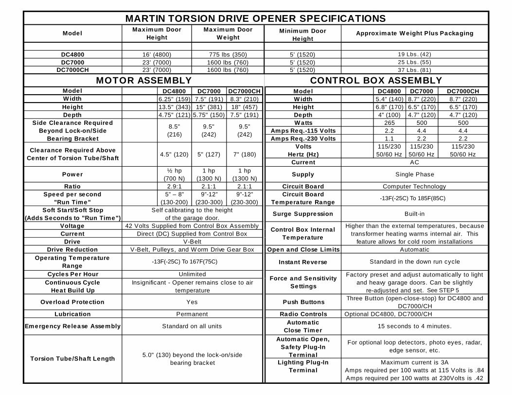
DC4800 for torsion spring doors up to 16' (4800) High Or up to 775 lbs. (350) DC7000 for torsion spring doors up to 23' (7000) High Or up to 1,600 lbs. (760) DC7000CH for torsion spring doors up to 23’ (7000) High Or up to 1,600 lbs. (760)
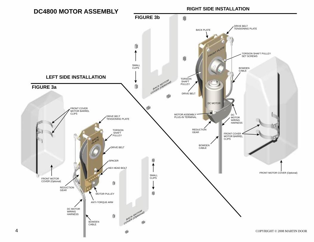
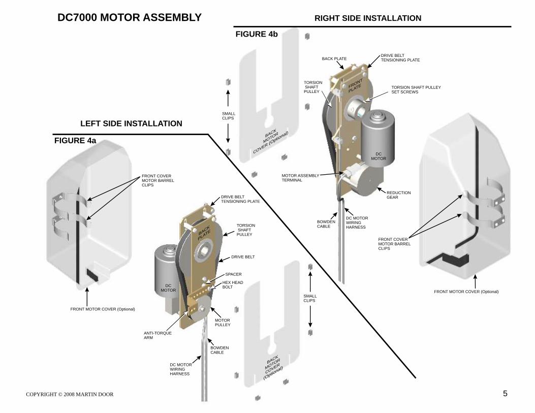
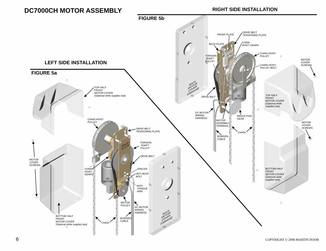
Motor Assembly See Figure 3a to 5b and Step 1DC Motor with Reduction GearMotor PulleyTorsion-Shaft Pulley with Set ScrewsDrive BeltDrive Belt Tensioning PlateBack PlateFront PlateFront and Back Motor CoverAnti-torque Arm with Bolts, Spacer, NutChain Hoist (DC7000CH)
Emergency Release Assembly See Figure 6a to 9b and Step 2Emergency Release Lever with Mounting Bracket, two Bolts and NutsBowden Cable with Cable Post and D-ShackleScrew Hook with Lock NutChain Extension Package
Control Box Assembly See Figure 10a to 11b and Step 3Control Box with Screws, Conduit OutletsControl Box Lid With Screws and Open, Close, Stop Push ButtonsCircuit Board with Plug-In Terminals, LED’s, Dip Switches, TransformerLow Voltage DC Motor Wiring Harness6’ (1830) Power Cord with 3-Prong Plug
Lighting See Page 22
Radio Control See Page 23, 24Radio Receiver with Low Voltage Wiring871 Receiver Module2-Button Transmitter
Extras2-Button Transmitter3-Button (keychain) Transmitter4-Button TransmitterMounting Plate (pocket) for Mini TransmitterWireless Keyless Entry
Push Button See Page 25_3-Button w/Box (open - close - stop)1-Button w/Box (open, stop, close, stop)1-Button (door bell type) with 2-Conductor Wire4-Conductor Wire (green, blue, red, white)
Key Switches See Page 25_Exterior w/BoxExterior w/PlateExterior/Interior w/Box (key open - close - stop)
Photo-Eyes Magnetic Loop Detector8070 Automatic Side Lock872 Side Lock Module82-TLM Traffic Light Module - Door Closed 1/Lock82-DTLM Traffic Light Module - Door Open 1/Lock8830 Battery Backup
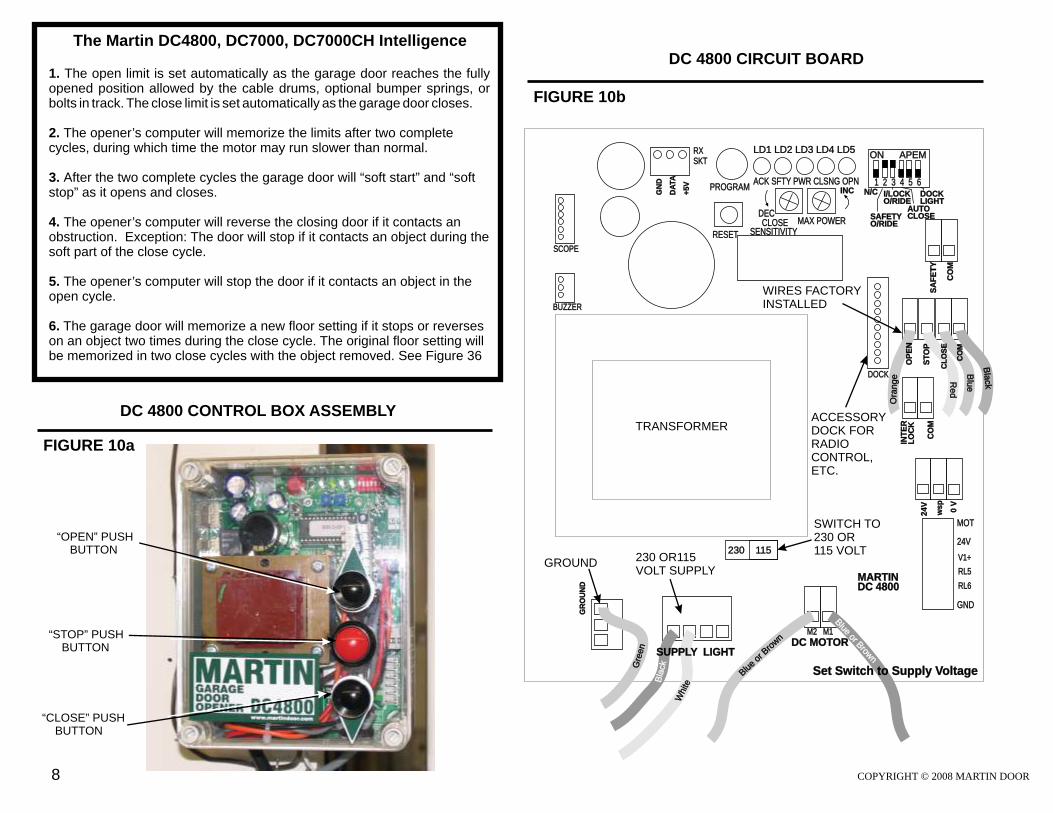
The Martin DC4800, DC7000, DC7000CH Intelligence 1. The open limit is set automatically as the garage door reaches opened position allowed by the cable drums, optional bumper springs, or bolts in track. The close limit is set automatically as the garage door closes.
2. The opener’s computer will memorize the limits after two complete cycles, during which time the motor may run slower than normal.
3. After the two complete cycles the garage door will “soft start” and “soft stop” as it opens and closes.
4. The opener’s computer will reverse the closing door if it contacts an obstruction. Exception: The door will stop if it contacts an object during the soft part of the close cycle.
5. The opener’s computer will stop the door if it contacts an object in the open cycle.
6. The garage door will memorize a new floor setting if it stops or reverses on an object two times during the close cycle. The original floor setting will be memorized in two close cycles with the object removed. See Figure 36
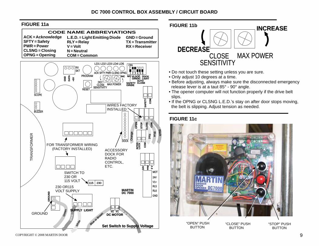
• Do not touch these setting unless you are sure.• Only adjust 10 degrees at a time.• Before adjusting, always make sure the disconnected emergency release lever is at a taut 85° - 90° angle.• The opener computer will not function properly if the drive belt slips.• If the OPNG or CLSNG L.E.D.’s stay on after door stops moving, the belt is slipping. Adjust tension as needed.
TR
AN
SF
OR
ME
R
WIRES FACTORYINSTALLED
DC MOTOR
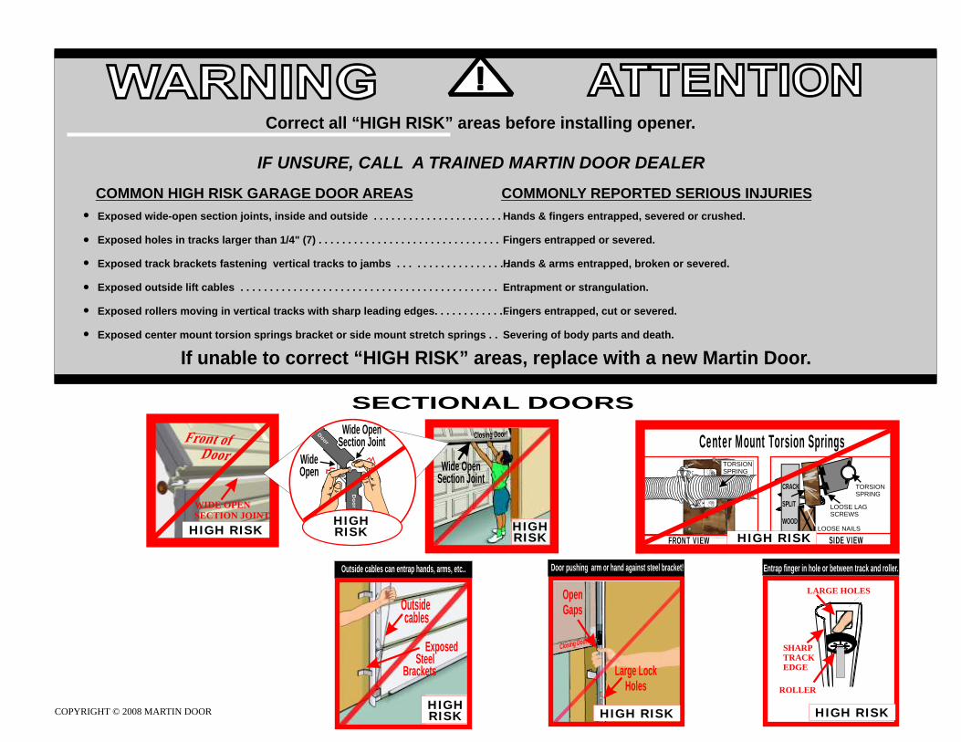
PREPARATION Correct all “High Risk” areas on the garage door before installation of the new Martin Torsion Drive Opener. If unable to correct, replace garage door with a new Martin Garage Door. See Back Page
Decide if the Motor Assembly will be mounted to the right side or left side of the garage door.
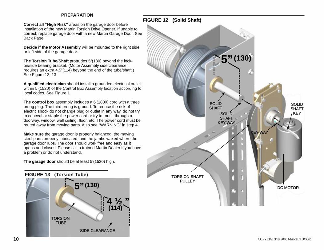
The Torsion Tube/Shaft protrudes 5”(130) beyond the lock-on/side bearing bracket. (Motor Assembly side clearance requires an extra 4.5”(114) beyond the end of the tube/shaft.) See Figure 12, 13
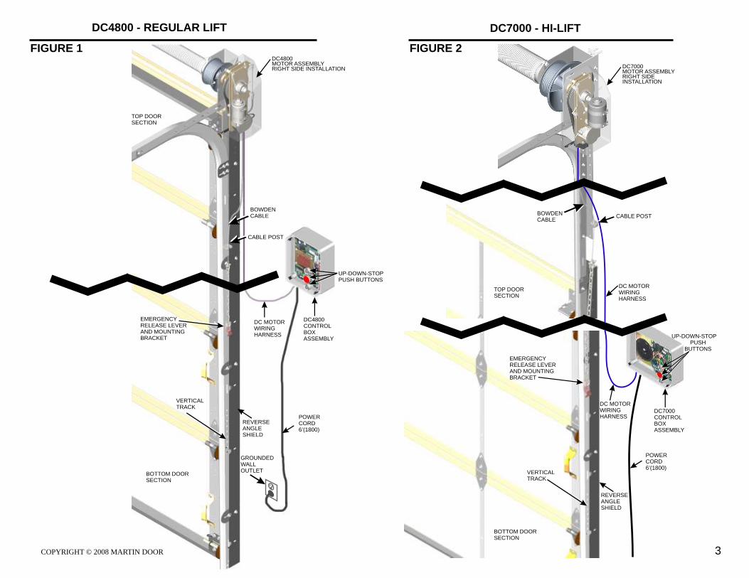
A qualified electrician should install a grounded electrical outlet within 5’(1520) of the Control Box Assembly location according to local codes. See Figure 1
The control box assembly includes a 6’(1800) cord with a three prong plug. The third prong is ground. To reduce the risk of electric shock do not change plug or outlet in any way. do not try to conceal or staple the power cord or try to rout it through a doorway, window, wall ceiling, floor, etc. The power cord must be routed away from moving parts. Also see “WARNING” in step 4. Make sure the garage door is properly balanced, the moving steel parts properly lubricated, and the jambs waxed where the garage door rubs. The door should work free and easy as it opens and closes. Please call a trained Martin Dealer if you have a problem or do not understand.
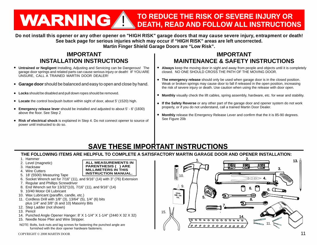
THE FOLLOWING ITEMS ARE HELPFUL TO COMPLETE A SATISFACTORY MARTIN GARAGE DOOR AND OPENER INSTALLATION:HammerLevel (magnetic)HacksawWire Cutters18’ (5500) Measuring TapeSocket Wrench set for 7/16” (11), and 9/16” (14) with 3” (76) ExtensionRegular and Phillips Screwdriver End Wrench set for 13/32”(10), 7/16” (11), and 9/16” (14)10/40 Motor Oil Lubricant Wax Lubricant (paraffin, candle, etc.)Cordless Drill with 1/8“ (3), 13/64” (5), 1/4” (6) bits plus 1/4” and 3/8” (6 and 10) Masonry BitsStep Ladder (not shown)PencilPunched Angle Opener Hanger: 8' X 1-1/4" X 1-1/4" (2440 X 32 X 32) Needle Nose Plier and Wire Stripper.
NOTE: Bolts, lock nuts and lag screws for fastening the punched angle arefurnished with the door opener hardware fasteners.
1.2.3.4.5.6.7.8.9.
10.11.
12.13.14.15.
2.
3.
6.9.
WA
X L
UB
E
10/40OMTO R
OIL
11.
10.4.
1.
7.
MT
R
S
AOD
A
GE
ROG ITARM
N
14.
8.
6.
5.
13.ALL MEASUREMENTS IN PARENTHESIS ( ) ARE MILLIMETERS IN THIS INSTRUCTION MANUAL.
IMPORTANTINSTALLATION INSTRUCTIONS
Do not install th is opener or any other opener on "HIGH RISK" garage doors that may cause severe injury, entrapment or death!See back page for serious injuries which may occur if “HIGH RISK” areas are left uncorrected.
Martin Finger Shield Garage Doors are “Low Risk”.
Untrained or Negligent Installing, Adjusting and Servicing can be Dangerous! The garage door springs and related parts can cause serious injury or death! IF YOU ARE UNSURE, CALL A TRAINED MARTIN DOOR DEALER!
Garage door should be balanced and easy to open and close by hand.
Locks should be disabled and pull down ropes should be removed.
Locate the control box/push button within sight of door, about 5' (1520) high.
Emergency release lever should be installed and adjusted to about 5’ - 6' (1830) above the floor. See Step 2
Risk of electrical shock is explained in Step 4. Do not connect opener to source of power until instructed to do so.
IMPORTANTMAINTENANCE & SAFETY INSTRUCTIONS
Always keep the moving door in sight and away from people and objects until it is completely closed. NO ONE SHOULD CROSS THE PATH OF THE MOVING DOOR.
The emergency release should only be used when garage door is in the closed position. Weak or broken springs may cause door to fall if released in the open position, increasing the risk of severe injury or death. Use caution when using the release with door open.
Monthly visually check the lift cables, spring assembly, hardware, etc. for wear and stability.
If the Safety Reverse or any other part of the garage door and opener system do not work properly, or if you do not understand, call a trained Martin Door Dealer.
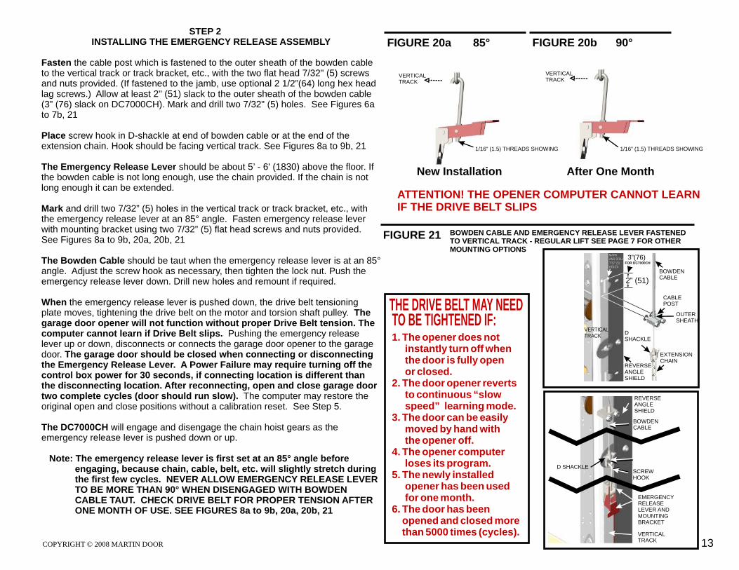
Monthly release the Emergency Release Lever and confirm that the it is 85-90 degrees. See Figure 20b
SAVE THESE IMPORTANT INSTRUCTIONS
15.
! TO REDUCE THE RISK OF SEVERE INJURY OR DEATH, READ AND FOLLOW ALL INSTRUCTIONS
INSTALLATION INSTRUCTIONS FOR THE MARTIN COMMERCIAL DC4800, DC7000, DC7000CH GARAGE DOOR OPENERS
THESE INSTRUCTIONS ARE INTENDED FOR PROFESSIONAL GARAGE DOOR OPENER INSTALLERS. READ THROUGH THE COMPLETE INSTRUCTION, MANUAL, SPECIFICATIONS AND APPLICABLE OPTIONAL INSTRUCTIONS BEFORE BEGINNING.
STEP 1 INSTALLING THE MOTOR ASSEMBLY
Study
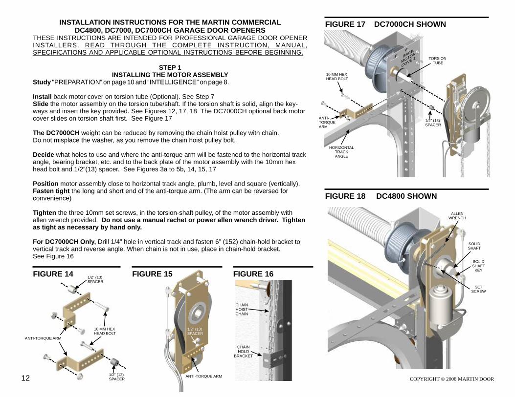
The DC7000CH weight can be reduced by removing the chain hoist pulley with chain.Do not misplace the washer, as you remove the chain hoist pulley bolt.
"PREPARATION” on page 10 and “INTELLIGENCE” on page 8.
Install back motor cover on torsion tube (Optional). See Step 7Slide the motor assembly on the torsion tube/shaft. If the torsion shaft is solid, align the key-ways and insert the key provided. See Figures 12, 17, 18 The DC7000CH optional back motor cover slides on torsion shaft first. See Figure 17
Decide what holes to use and where the anti-torque arm will be fastened to the horizontal track angle, bearing bracket, etc. and to the back plate of the motor assembly with the 10mm hex head bolt and 1/2”(13) spacer. See Figures 3a to 5b, 14, 15, 17
Position motor assembly close to horizontal track angle, plumb, level and square (vertically). Fasten tight the long and short end of the anti-torque arm. (The arm can be reversed for convenience)
Tighten the three 10mm set screws, in the torsion-shaft pulley, of the motor assembly with allen wrench provided. Do not use a manual rachet or power allen wrench driver. Tighten as tight as necessary by hand only.
For DC7000CH Only, Drill 1/4” hole in vertical track and fasten 6” (152) chain-hold bracket to vertical track and reverse angle. When chain is not in use, place in chain-hold bracket. See Figure 16
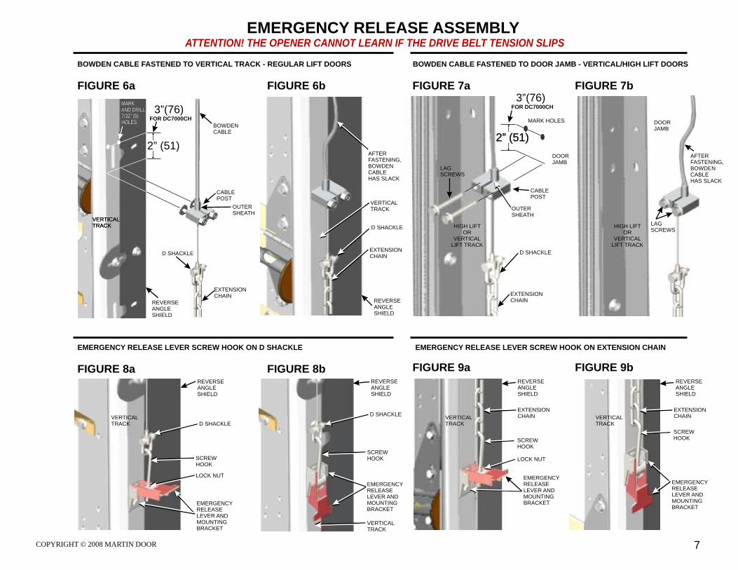
Fasten the cable post which is fastened to the outer sheath of the bowden cable to the vertical track or track bracket, etc., with the two flat head 7/32" (5) screws and nuts provided. (If fastened to the jamb, use optional 2 1/2”(64) long hex head lag screws.) Allow at least 2" (51) slack to the outer sheath of the bowden cable (3” (76) slack on DC7000CH). Mark and drill two 7/32" (5) holes. See Figures 6a to 7b, 21
Place screw hook in D-shackle at end of bowden cable or at the end of the extension chain. Hook should be facing vertical track. See Figures 8a to 9b, 21
The Emergency Release Lever should be about 5’ - 6' (1830) above the floor. If the bowden cable is not long enough, use the chain provided. If the chain is not long enough it can be extended.
Mark and drill two 7/32” (5) holes in the vertical track or track bracket, etc., with the emergency release lever at an 85° angle. Fasten emergency release lever with mounting bracket using two 7/32” (5) flat head screws and nuts provided. See Figures 8a to 9b, 20a, 20b, 21 The Bowden Cable should be taut when the emergency release lever is at an 85° angle. Adjust the screw hook as necessary, then tighten the lock nut. Push the emergency release lever down. Drill new holes and remount if required.
When the emergency release lever is pushed down, the drive belt tensioning plate moves, tightening the drive belt on the motor and torsion shaft pulley. The garage door opener will not function without proper Drive Belt tension. The computer cannot learn if Drive Belt slips. Pushing the emergency release lever up or down, disconnects or connects the garage door opener to the garage door. The garage door should be closed when connecting or disconnecting the Emergency Release Lever. A Power Failure may require turning off the control box power for 30 seconds, if connecting location is different than the disconnecting location. After reconnecting, open and close garage door two complete cycles (door should run slow). The computer may restore the original open and close positions without a calibration reset. See Step 5.
The DC7000CH will engage and disengage the chain hoist gears as the emergency release lever is pushed down or up.
Note: The emergency release lever is first set at an 85° angle before engaging, because chain, cable, belt, etc. will slightly stretch during the first few cycles. NEVER ALLOW EMERGENCY RELEASE LEVER TO BE MORE THAN 90° WHEN DISENGAGED WITH BOWDEN CABLE TAUT. CHECK DRIVE BELT FOR PROPER TENSION AFTER ONE MONTH OF USE. SEE FIGURES 8a to 9b, 20a, 20b, 21
THE DRIVE BELT MAY NEED TO BE TIGHTENED IF:1. The opener does not instantly turn off when the door is fully open or closed.2. The door opener reverts to continuous “slow speed” learning mode.3. The door can be easily moved by hand with the opener off.4. The opener computer loses its program.5. The newly installed opener has been used for one month.6. The door has been opened and closed more than 5000 times (cycles).
VERTICALTRACK
VERTICALTRACK
STEP 3INSTALLING THE CONTROL BOX ASSEMBLY
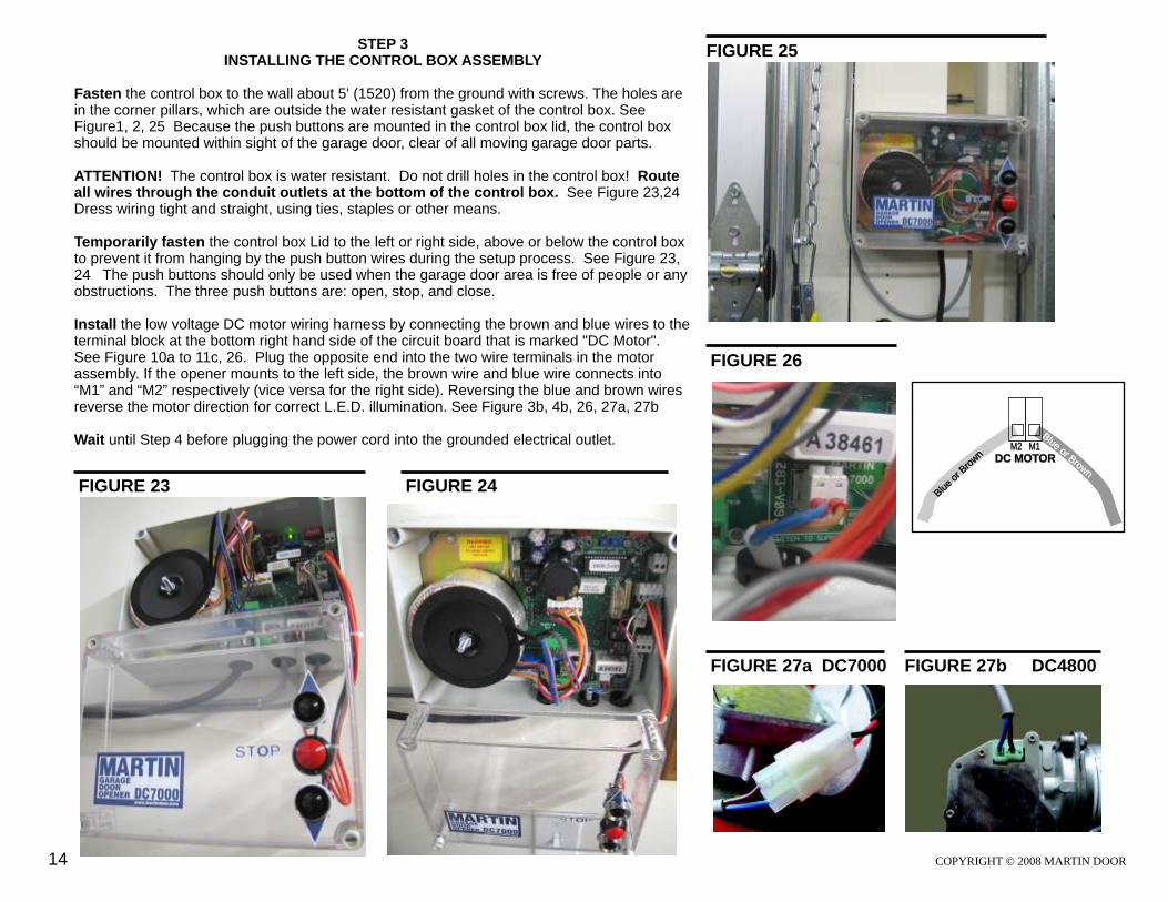
Fasten the control box to the wall about 5' (1520) from the ground with screws. The holes are in the corner pillars, which are outside the water resistant gasket of the control box. See Figure1, 2, 25 Because the push buttons are mounted in the control box lid, the control box should be mounted within sight of the garage door, clear of all moving garage door parts.
ATTENTION! The control box is water resistant. Do not drill holes in the control box! Route all wires through the conduit outlets at the bottom of the control box. See Figure 23,24 Dress wiring tight and straight, using ties, staples or other means.
Temporarily fasten the control box Lid to the left or right side, above or below the control box to prevent it from hanging by the push button wires during the setup process. See Figure 23, 24 The push buttons should only be used when the garage door area is free of people or any obstructions. The three push buttons are: open, stop, and close.
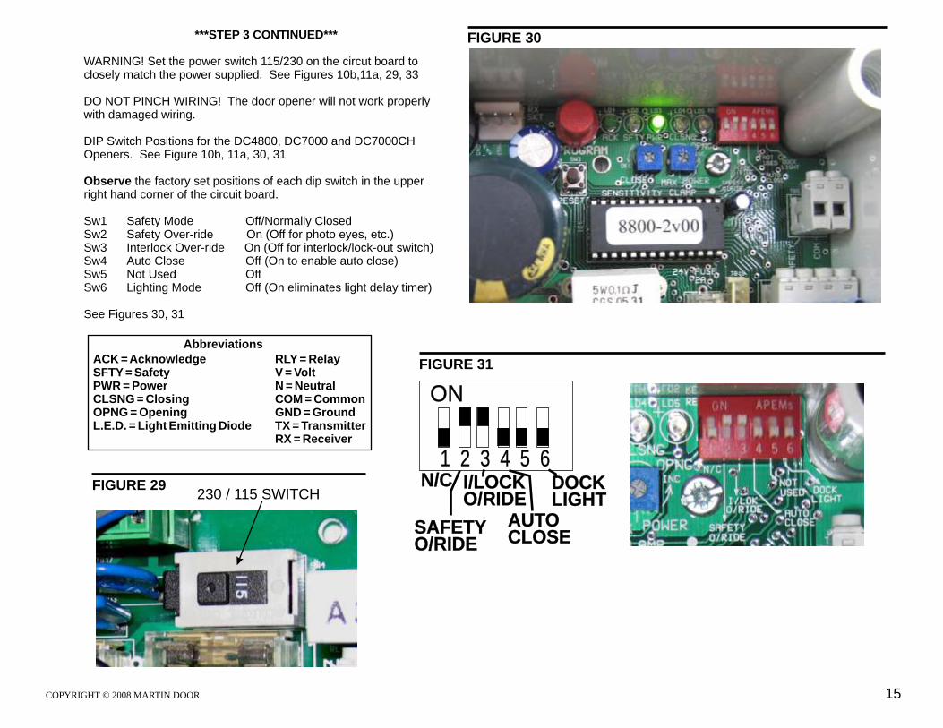
Install the low voltage DC motor wiring harness by connecting the brown and blue wires to the terminal block at the bottom right hand side of the circuit board that is marked "DC Motor". See Figure 10a to 11c, 26. Plug the opposite end into the two wire terminals in the motor assembly. If the opener mounts to the left side, the brown wire and blue wire connects into “M1” and “M2” respectively (vice versa for the right side). Reversing the blue and brown wires reverse the motor direction for correct L.E.D. illumination. See Figure 3b, 4b, 26, 27a, 27b
Wait until Step 4 before plugging the power cord into the grounded electrical outlet.
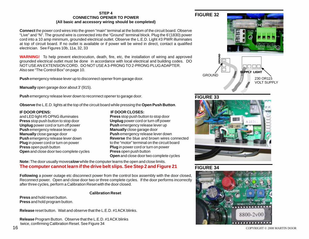
WARNING! Set the power switch 115/230 on the circut board to closely match the power supplied. See Figures 10b,11a, 29, 33
DO NOT PINCH WIRING! The door opener will not work properly with damaged wiring.
DIP Switch Positions for the DC4800, DC7000 and DC7000CH Openers. See Figure 10b, 11a, 30, 31
Observe the factory set positions of each dip switch in the upper right hand corner of the circuit board.
Sw1 Safety Mode Off/Normally ClosedSw2 Safety Over-ride On (Off for photo eyes, etc.)Sw3 Interlock Over-ride On (Off for interlock/lock-out switch)Sw4 Auto Close Off (On to enable auto close)Sw5 Not Used OffSw6 Lighting Mode Off (On eliminates light delay timer)
(All basic and accessory wiring should be completed)
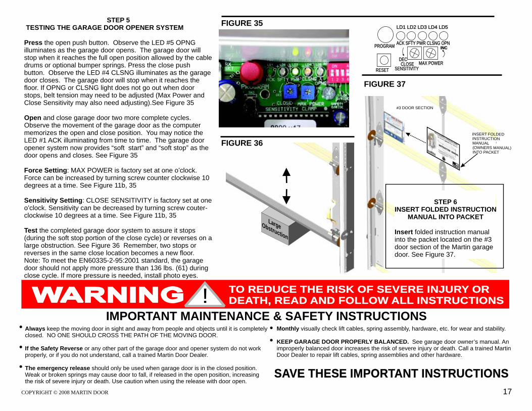
Connect “Live” and “N”. The ground wire is connected into the “Ground” terminal block. Plug the 6’(1830) power cord into a 10 amp minimum, grounded electrical outlet. Observe the L.E.D. Light #3 PWR illuminates at top of circuit board. If no outlet is available or if power will be wired in direct, contact a qualified electrician. See Figures 10b, 11a, 32, 33
To help prevent electrocution, death, fire, etc, the installation of wiring and approved grounded electrical outlet must be done in accordance with local electrical and building codes. DO NOT USE AN EXTENSION CORD. DO NOT USE A 3-PRONG TO 2-PRONG PLUG ADAPTER.Also see “The Control Box” on page 10.
Push emergency release lever up to disconnect opener from garage door.
Manually open garage door about 3' (915).
Push emergency release lever down to reconnect opener to garage door.
Observe the L.E.D. lights at the top of the circuit board while pressing the Open Push Button.
the power cord wires into the green “main” terminal at the bottom of the circuit board. Observe
Note: The door usually movesslow while the computer learns the open and close limits.
Following a power outage etc disconnect power from the control box assembly with the door closed, Reconnect power. Open and close door two or three complete cycles. If the door performs incorrectly after three cycles, perform a Calibration Reset with the door closed.
Calibration Reset Press and hold reset button. Press and hold program button.
Release reset button. Wait and observe that the L.E.D. #1 ACK blinks.
Release Program Button. Observe that the L.E.D. #1 ACK blinks twice, confirming Calibration Reset. See Figure 34
The computer cannot learn if the drive belt slips. See Step 2 and Figure 21
IF DOOR OPENS:and LED light #5 OPNG illuminatesPress stop push button to stop doorUnplug power cord or turn off power Push emergency release lever up Manually close garage door Push emergency release lever downPlug in power cord or turn on powerPress open push buttonOpen and close door two complete cycles
IF DOOR CLOSES:Press stop push button to stop doorUnplug power cord or turn off powerPush emergency release lever up Manually close garage door Push emergency release lever down Reverse the blue and brown wires connected to the “motor” terminal on the circuit board Plug in power cord or turn on powerPress open push buttonOpen and close door two complete cycles
FIGURE 33
FIGURE 34
16
GR
OU
ND
230 OR115 VOLT SUPPLY
GROUND re
Ge
n
lac
Bk
hW
ite
SUPPLY LIGHT
STEP 5 TESTING THE GARAGE DOOR OPENER SYSTEM
Press the open push button. Observe the LED #5 OPNG illuminates as the garage door opens. The garage door will stop when it reaches the full open position allowed by the cable drums or optional bumper springs. Press the close push button. Observe the LED #4 CLSNG illuminates as the garage door closes. The garage door will stop when it reaches the floor. If OPNG or CLSNG light does not go out when door stops, belt tension may need to be adjusted (Max Power and Close Sensitivity may also need adjusting).See Figure 35
Open and close garage door two more complete cycles. Observe the movement of the garage door as the computer memorizes the open and close position. You may notice the LED #1 ACK illuminating from time to time. The garage door opener system now provides “soft start” and “soft stop” as the door opens and closes. See Figure 35
Force Setting: MAX POWER is factory set at one o’clock. Force can be increased by turning screw counter clockwise 10 degrees at a time. See Figure 11b, 35
Sensitivity Setting: CLOSE SENSITIVITY is factory set at one o’clock. Sensitivity can be decreased by turning screw couter-clockwise 10 degrees at a time. See Figure 11b, 35
Test the completed garage door system to assure it stops (during the soft stop portion of the close cycle) or reverses on a large obstruction. See Figure 36 Remember, two stops or reverses in the same close location becomes a new floor.Note: To meet the EN60335-2-95:2001 standard, the garage door should not apply more pressure than 136 lbs. (61) during close cycle. If more pressure is needed, install photo eyes.
IMPORTANT MAINTENANCE & SAFETY INSTRUCTIONS Always keep the moving door in sight and away from people and objects until it is completely closed. NO ONE SHOULD CROSS THE PATH OF THE MOVING DOOR.
If the Safety Reverse or any other part of the garage door and opener system do not work properly, or if you do not understand, call a trained Martin Door Dealer.
The emergency release should only be used when garage door is in the closed position.Weak or broken springs may cause door to fall, if released in the open position, increasing the risk of severe injury or death. Use caution when using the release with door open.
SAVE THESE IMPORTANT INSTRUCTIONS
Monthly visually check lift cables, spring assembly, hardware, etc. for wear and stability.
KEEP GARAGE DOOR PROPERLY BALANCED. See garage door owner’s manual. An improperly balanced door increases the risk of severe injury or death. Call a trained Martin Door Dealer to repair lift cables, spring assemblies and other hardware.
FIGURE 37
FIGURE 36
FIGURE 35
r e
La gObsti
ruct on
STEP 6
INSERT FOLDED INSTRUCTION MANUAL INTO PACKET
Insert folded instruction manual into the packet located on the #3 door section of the Martin garage door. See Figure 37.
#3 DOOR SECTION
N LI SERT FO DED IN CSTRU TION MANUALO ER AL( WN S MANU )
TIN O PACKET
! TO REDUCE THE RISK OF SEVERE INJURY OR DEATH, READ AND FOLLOW ALL INSTRUCTIONS
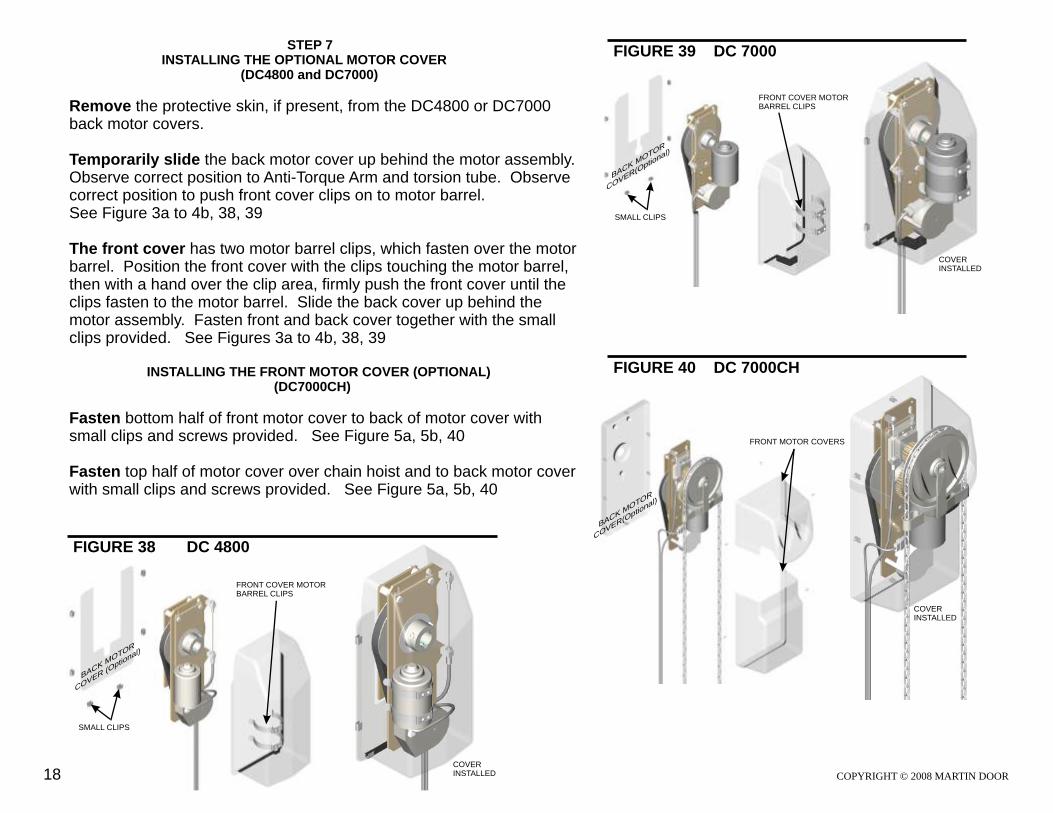
FIGURE 39 DC 7000 STEP 7 INSTALLING THE OPTIONAL MOTOR COVER
(DC4800 and DC7000)
Remove the protective skin, if present, from the DC4800 or DC7000 back motor covers.
Temporarily slide the back motor cover up behind the motor assembly. Observe correct position to Anti-Torque Arm and torsion tube. Observe correct position to push front cover clips on to motor barrel. See Figure 3a to 4b, 38, 39
The front cover has two motor barrel clips, which fasten over the motor barrel. Position the front cover with the clips touching the motor barrel, then with a hand over the clip area, firmly push the front cover until the clips fasten to the motor barrel. Slide the back cover up behind the motor assembly. Fasten front and back cover together with the small clips provided. See Figures 3a to 4b, 38, 39
INSTALLING THE FRONT MOTOR COVER (OPTIONAL) (DC7000CH)
Fasten bottom half of front motor cover to back of motor cover with small clips and screws provided. See Figure 5a, 5b, 40
Fasten top half of motor cover over chain hoist and to back motor cover with small clips and screws provided. See Figure 5a, 5b, 40
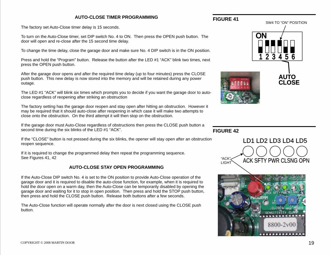
The factory set Auto-Close timer delay is 15 seconds.
To turn on the Auto-Close timer, set DIP switch No. 4 to ON. Then press the OPEN push button. The door will open and re-close after the 15 second time delay.
To change the time delay, close the garage door and make sure No. 4 DIP switch is in the ON position.
Press and hold the “Program” button. Release the button after the LED #1 “ACK” blink two times, next press the OPEN push button.
After the garage door opens and after the required time delay (up to four minutes) press the CLOSE push button. This new delay is now stored into the memory and will be retained during any power outage.
The LED #1 “ACK” will blink six times which prompts you to decide if you want the garage door to auto-close regardless of reopening after striking an obstruction
The factory setting has the garage door reopen and stay open after hitting an obstruction. However it may be required that it should auto-close after reopening in which case it will make two attempts to close onto the obstruction. On the third attempt it will then stop on the obstruction.
If the garage door must Auto-Close regardless of obstructions then press the CLOSE push button a second time during the six blinks of the LED #1 “ACK”.
If the “CLOSE” button is not pressed during the six blinks, the opener will stay open after an obstruction reopen sequence.
If it is required to change the programmed delay then repeat the programming sequence. See Figures 41, 42
AUTO-CLOSE STAY OPEN PROGRAMMING
If the Auto-Close DIP switch No. 4 is set to the ON position to provide Auto-Close operation of the garage door and it is required to disable the auto-close function, for example, when it is required to hold the door open on a warm day, then the Auto-Close can be temporarily disabled by opening the garage door and waiting for it to stop in open position. Then press and hold the STOP push button, then press and hold the CLOSE push button. Release both buttons after a few seconds.
The Auto-Close function will operate normally after the door is next closed using the CLOSE push button.
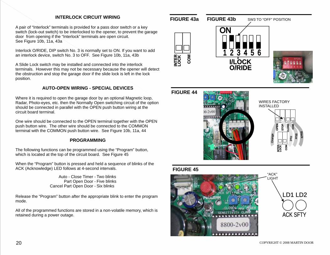
A pair of “Interlock” terminals is provided for a pass door switch or a key switch (lock-out switch) to be interlocked to the opener, to prevent the garage door from opening if the “Interlock” terminals are open circuit. See Figure 10b, 11a, 43a
Interlock O/RIDE, DIP switch No. 3 is normally set to ON. If you want to add an interlock device, switch No. 3 to OFF. See Figure 10b, 11a, 43b
A Slide Lock switch may be installed and connected into the interlock terminals. However this may not be necessary because the opener will detect the obstruction and stop the garage door if the slide lock is left in the lock position.
AUTO-OPEN WIRING - SPECIAL DEVICES
Where it is required to open the garage door by an optional Magnetic loop, Radar, Photo-eyes, etc. then the Normally Open switching circuit of the option should be connected in parallel with the OPEN push button wiring at the circuit board terminal.
One wire should be connected to the OPEN terminal together with the OPEN push button wire. The other wire should be connected to the COMMON terminal with the COMMON push button wire. See Figure 10b, 11a, 44
PROGRAMMING
The following functions can be programmed using the “Program” button, which is located at the top of the circuit board. See Figure 45
When the “Program” button is pressed and held a sequence of blinks of the ACK (Acknowledge) LED follows at 4-second intervals.
Release the “Program” button after the appropriate blink to enter the program mode.
All of the programmed functions are stored in a non-volatile memory, which is retained during a power outage.
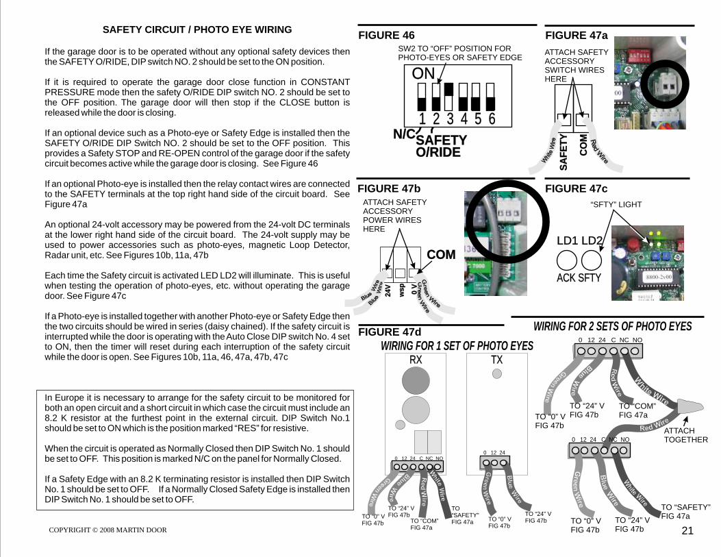
If the garage door is to be operated without any optional safety devices then the SAFETY O/RIDE, DIP switch NO. 2 should be set to the ON position.
If it is required to operate the garage door close function in CONSTANT PRESSURE mode then the safety O/RIDE DIP switch NO. 2 should be set to the OFF position. The garage door will then stop if the CLOSE button is released while the door is closing.
If an optional device such as a Photo-eye or Safety Edge is installed then the SAFETY O/RIDE DIP Switch NO. 2 should be set to the OFF position. This provides a Safety STOP and RE-OPEN control of the garage door if the safety circuit becomes active while the garage door is closing. See Figure 46
If an optional Photo-eye is installed then the relay contact wires are connected to the SAFETY terminals at the top right hand side of the circuit board. See Figure 47a
An optional 24-volt accessory may be powered from the 24-volt DC terminals at the lower right hand side of the circuit board. The 24-volt supply may be used to power accessories such as photo-eyes, magnetic Loop Detector, Radar unit, etc. See Figures 10b, 11a, 47b
Each time the Safety circuit is activated LED LD2 will illuminate. This is useful when testing the operation of photo-eyes, etc. without operating the garage door. See Figure 47c
If a Photo-eye is installed together with another Photo-eye or Safety Edge then the two circuits should be wired in series (daisy chained). If the safety circuit is interrupted while the door is operating with the Auto Close DIP switch No. 4 set to ON, then the timer will reset during each interruption of the safety circuit while the door is open. See Figures 10b, 11a, 46, 47a, 47b, 47c
In Europe it is necessary to arrange for the safety circuit to be monitored for both an open circuit and a short circuit in which case the circuit must include an 8.2 K resistor at the furthest point in the external circuit. DIP Switch No.1 should be set to ON which is the position marked “RES” for resistive.
When the circuit is operated as Normally Closed then DIP Switch No. 1 should be set to OFF. This position is marked N/C on the panel for Normally Closed.
If a Safety Edge with an 8.2 K terminating resistor is installed then DIP Switch No. 1 should be set to OFF. If a Normally Closed Safety Edge is installed then DIP Switch No. 1 should be set to OFF.
FIGURE 47aFIGURE 46
21
ON
1 2 3 4 5 6
SAFETYO/RIDE
SW2 TO “OFF” POSITION FORPHOTO-EYES OR SAFETY EDGE
For high garage doors, there may be a requirement to only open the door to a pre-determined height.
Before programming the part open position the installation and initial calibration of the garage door must be completed and garage door should be cycled at least five times.
To program “partially open” height, start with the garage door fully closed.
Press and hold the program button until the LED #1 “ACK” blinks five times.
Release the program button and then press the OPEN push button, the garage door will now start opening.
At the required open position press the STOP push button. The LED #1 “ACK” will blink two times, confirming a successful program.
The garage door will now open to this programmed position.
To fully open the garage door, press the OPEN push button with the garage door at the part open position. It will open completely.
To return to its normal open and close position, close the garage door. Press Program button until the LED #1 “ACK” blink six times.
Release the Program button and the LED #1 “ACK” will blink two times, confirming the change.
See Figure 48
22
LD1 LD2
ACK SFTY
“ACK” LIGHT
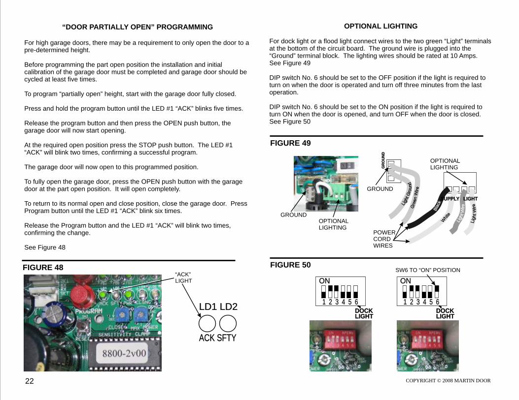
OPTIONAL LIGHTING
For dock light or a flood light connect wires to the two green “Light” terminals at the bottom of the circuit board. The ground wire is plugged into the “Ground” terminal block. The lighting wires should be rated at 10 Amps. See Figure 49
DIP switch No. 6 should be set to the OFF position if the light is required to turn on when the door is operated and turn off three minutes from the last operation.
DIP switch No. 6 should be set to the ON position if the light is required to turn ON when the door is opened, and turn OFF when the door is closed. See Figure 50
FIGURE 49
FIGURE 50
GR
OU
ND
OPTIONALLIGHTING
GROUND
OPTIONALLIGHTING
GROUND
ON
1 2 3 4 5 6DOCKLIGHT
ON
1 2 3 4 5 6DOCKLIGHT
SW6 TO “ON” POSITION
Bla
ckW
hite
SUPPLY LIGHT
POWERCORDWIRES
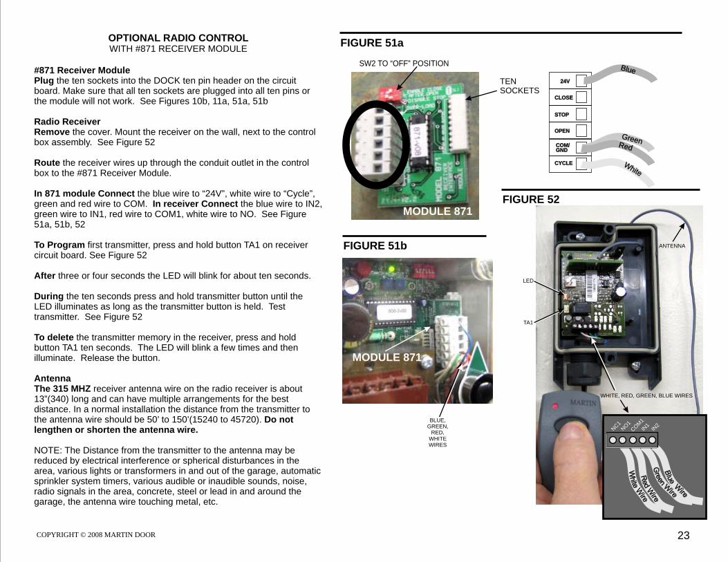
OPTIONAL RADIO CONTROL WITH #871 RECEIVER MODULE
#871 Receiver Module Plug the ten sockets into the DOCK ten pin header on the circuit board. Make sure that all ten sockets are plugged into all ten pins or the module will not work. See Figures 10b, 11a, 51a, 51b
Radio ReceiverRemove the cover. Mount the receiver on the wall, next to the control box assembly. See Figure 52
Route the receiver wires up through the conduit outlet in the control box to the #871 Receiver Module.
In 871 module Connect the blue wire to “24V”, white wire to “Cycle”, green and red wire to COM. In receiver Connect the blue wire to IN2, green wire to IN1, red wire to COM1, white wire to NO. See Figure 51a, 51b, 52
To Program first transmitter, press and hold button TA1 on receiver circuit board. See Figure 52
After three or four seconds the LED will blink for about ten seconds.
During the ten seconds press and hold transmitter button until the LED illuminates as long as the transmitter button is held. Test transmitter. See Figure 52
To delete the transmitter memory in the receiver, press and hold button TA1 ten seconds. The LED will blink a few times and then illuminate. Release the button.
AntennaThe 315 MHZ receiver antenna wire on the radio receiver is about 13”(340) long and can have multiple arrangements for the best distance. In a normal installation the distance from the transmitter to the antenna wire should be 50’ to 150’(15240 to 45720). Do not lengthen or shorten the antenna wire.
NOTE: The Distance from the transmitter to the antenna may be reduced by electrical interference or spherical disturbances in the area, various lights or transformers in and out of the garage, automatic sprinkler system timers, various audible or inaudible sounds, noise, radio signals in the area, concrete, steel or lead in and around the garage, the antenna wire touching metal, etc.
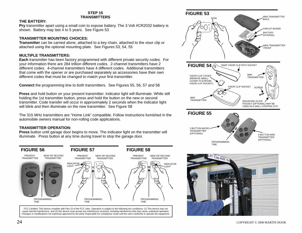
THE BATTERY:Pry transmitter apart using a small coin to expose battery. The 3 Volt #CR2032 battery is shown. Battery may last 4 to 5 years. See Figure 53
TRANSMITTER MOUNTING CHOICES:Transmitter can be carried alone, attached to a key chain, attached to the visor clip or attached using the optional mounting plate. See Figures 53, 54, 55 MULTIPLE TRANSMITTERS:Each transmitter has been factory programmed with different private security codes. For your information there are 284 trillion different codes. 2-channel transmitters have 2 different codes. 4-channel transmitters have 4 different codes. Additional transmitters that come with the opener or are purchased separately as accessories have their own different codes that must be changed to match your first transmitter.
Connect the programming tine to both transmitters. See Figures 55, 56, 57 and 58 Press and hold button on your present transmitter. Indicator light will illuminate. While still holding the 1st transmitter button, press and hold the button on the new or second transmitter. Code transfer will occur in approximately 2 seconds when the indicator light will blink and then illuminate on the new transmitter. See Figure 58
The 315 MHz transmitters are “Home Link” compatible. Follow instructions furnished in the automobile owners manual for non-rolling code applications.
TRANSMITTER OPERATION:Press button until garage door begins to move. The indicator light on the transmitter will illuminate. Press button at any time during travel to stop the garage door.
FIGURE 54
FIGURE 55
FIGURE 56
SNAP VISOR CLIP INTO SOCKET
FIGURE 57 FIGURE 58
FCC Certified: This device complies with Part 15 of the FCC rules. Operation is subject to the following two conditions: (1) This device may not cause harmful interference, and (2) this device must accept any interference received, including interference that may cause undesired operation. Changes or modifications not expressly approved by the party responsible for compliance could void the user's authority to operate the equipment.
VISOR CLIP COVER(REMOVE SMALL COVER TO EXPOSE VISOR CLIP SOCKET)
VISOR CLIP SOCKET
PROGRAMMINGTINE
MINI TRANSMITTERBACK
BATTERY(#CR2032)
MINI TRANSMITTERFRONT
CIRCUIT BOARD
3 BUTTON MICRO TRANSMITTER(OPTIONAL)
4 BUTTON MINI TRANSMITTER(OPTIONAL)
MRT N
AI
SCREW
MOUNTING PLATE POCKET (OPTIONAL) MAY BE USED AS A WALL CONTROL ETC.
MINITRANSMITTER
PROGRAMMINGTINE
PROGRAMMINGTINE
PROGRAMMINGTINE
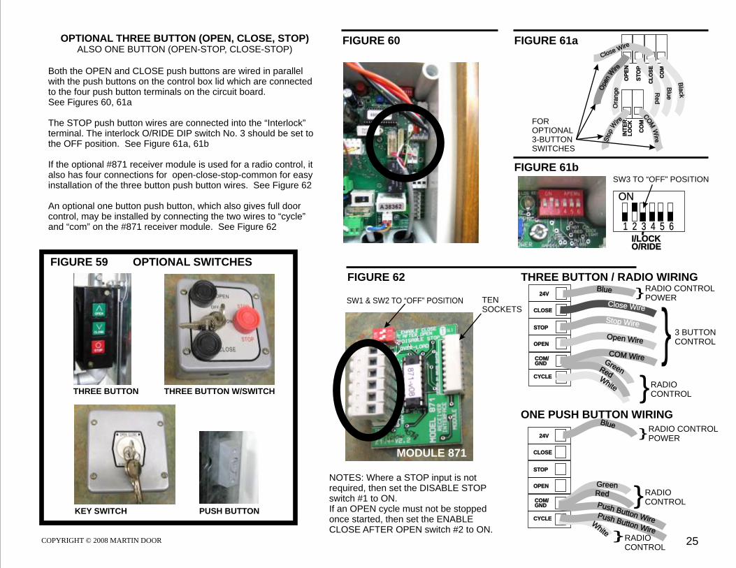
OPTIONAL THREE BUTTON (OPEN, CLOSE, STOP)ALSO ONE BUTTON (OPEN-STOP, CLOSE-STOP)
Both the OPEN and CLOSE push buttons are wired in parallel with the push buttons on the control box lid which are connected to the four push button terminals on the circuit board. See Figures 60, 61a
The STOP push button wires are connected into the “Interlock” terminal. The interlock O/RIDE DIP switch No. 3 should be set to the OFF position. See Figure 61a, 61b
If the optional #871 receiver module is used for a radio control, it also has four connections for open-close-stop-common for easy installation of the three button push button wires. See Figure 62
An optional one button push button, which also gives full door control, may be installed by connecting the two wires to “cycle” and “com” on the #871 receiver module. See Figure 62
NOTES: Where a STOP input is not required, then set the DISABLE STOP switch #1 to ON. If an OPEN cycle must not be stopped once started, then set the ENABLE CLOSE AFTER OPEN switch #2 to ON.
FOR OPTIONAL3-BUTTONSWITCHES
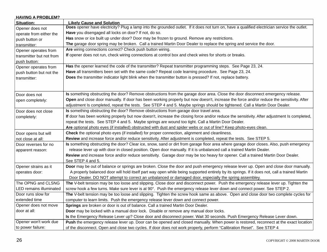
HAVING A PROBLEM?
Situation: Likely Cause and Solution
Opener does not
operate from either the
push button or
transmitter:
Opener operates from
transmitter but not from
push button:
Opener operates from
push button but not the
transmitter:
Door does not
open completely:
Door does not close
completely:
Door opens but will
not close at all:
Door reverses for no
apparent reason:
Opener strains as it
operates door:
The OPNG and CLSNG
LED remains illuminated
Door runs slow for
extended time
Opener does not move
door at all:
Opener won't work due
to power failure:
Does opener have electricity? Plug a lamp into the grounded outlet. If it does not turn on, have a qualified electrician service the outlet.
Have you disengaged all locks on door? If not, do so.
Has snow or ice built up under door? Door may be frozen to ground. Remove any restrictions.
The garage door spring may be broken. Call a trained Martin Door Dealer to replace the spring and service the door.
Are wiring connections correct? Check push button wiring.
If opener does not run, check wiring connections at control box and check wires for shorts or breaks.
Has the opener learned the code of the transmitter? Repeat transmitter programming steps. See Page 23, 24.
Have all transmitters been set with the same code? Repeat code learning procedure. See Page 23, 24.
Does the transmitter indicator light blink when the transmitter button is pressed? If not, replace battery.
Is something obstructing the door? Remove obstructions from the garage door area. Close the door disconnect emergency release.
Open and close door manually. If door has been working properly but now doesn't, increase the force and/or reduce the sensitivity. After
adjustment Is completed, repeat the tests. See STEP 4 and 5. Maybe springs should be tightened. Call a Martin Door Dealer.
Is something obstructing the door? Remove obstructions from garage door travel area.
If door has been working properly but now doesn't, increase the closing force and/or reduce the sensitivity. After adjustment Is completed,
repeat the tests. See STEP 4 and 5. Maybe springs are wound too tight. Call a Martin Door Dealer.
Are optional photo eyes (if installed) obstructed with dust and spider webs or out of line? Keep photo-eyes clean.
Check the optional photo eyes (if installed) for proper connection, alignment and cleanliness.
Review and increase force and/or reduce sensitivity. After adjustment is completed, repeat the tests.
Is something obstructing the door? Clear ice, snow, sand or dirt from garage floor area where garage door closes. Also, push emergency
release lever up with door in closed position. Open door manually. If it is unbalanced call a trained Martin Dealer.
Review and increase force and/or reduce sensitivity. Garage door may be too heavy for opener. Call a trained Martin Door Dealer.
Door may be out of balance or springs are broken. Close the door and push emergency release lever up. Open and close door manually.
A properly balanced door will hold itself part way open while being supported entirely by its springs. If it does not, call a trained Martin
Door Dealer. DO NOT attempt to correct an unbalanced or damaged door, especially the spring assembley.
The V-belt tension may be too loose and slipping. Close door and disconnect power. Push the emergency release lever up. Tighten the
screw hook a few turns. Make sure lever is at 90°. Push the emergency release lever down and connect power. See STEP 2.
Springs are broken or door is out of balance. Call a trained Martin Door Dealer.
Door may be locked with a manual door lock. Disable or remove any manual door locks.
Is the Emergency Release Lever up? Close door and disconnect power. Wait 30 seconds. Push Emergency Release Lever down.
Push the emergency release lever up. Door can be opened and closed manually. When power is restored, reconnect at the exact location
of the disconnect. Open and close two cycles. If door does not work properly, perform “Calibration Reset”. See STEP 4
See STEP 5.
See STEP 4 and 5.
The V-belt tension may be too loose and slipping. Tighten the screw hook same as above. Open and close door two complete cycles for
computer to learn limits. Push the emergency release lever down and connect power.