Page 1
A-6004-005 (08/05)
HNF-3484
Revision 10
DOUBLE-SHELL TANK EMERGENCY PUMPING GUIDE
T. M. Blaak
Washington River Protection Solutions, LLC.
Date Published
July 2009
Prepared for the U.S. Department of Energy
Office of River Protection
Approved for public release; distribution unlimited
Page 2
HNF-3484 Rev. 10
2
CONTENTS
1.0 GENERAL INFORMATION ....................................................................................4
1.1 PURPOSE, SCOPE, AND BACKGROUND ..................................................4
1.2 DISCUSSION OF SPARE TANK SPACE ......................................................5
1.3 DISCUSSION OF INCREASING TANK LEVEL ..........................................7
1.4 NON-COMPLIANT TRANSFER LINES FOR EMERGENCY USE ..........11
1.5 NON-COMPLIANT PROCESS PITS FOR EMERGENCY USE ................13
1.6 SUMMARY OF INFORMATION PROVIDED ...........................................13
2.0 EQUIPMENT DESCRIPTION ................................................................................15
2.1 PRIMARY TANK PIT CONFIGURATION .................................................16
2.2 SECONDARY CONTAINMENT PIT CONFIGURATION .........................17
2.3 SUPPORT SYSTEMS ....................................................................................17
3.0 PLAN OF ACTION .................................................................................................18
3.1 REGULATORY REQUIREMENTS APPLICABLE TO LEAKING
DOUBLE-SHELL TANKS ............................................................................18
3.2 GENERAL STRATEGY ................................................................................19
3.3 POTENTIAL LEAK SCENARIOS ...............................................................20
3.3.1 Strategy for Emergency Pumping after a Minor Leak ..........................22
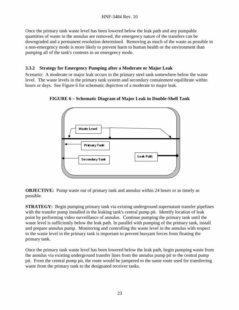
3.3.2 Strategy for Emergency Pumping after a Moderate or Major Leak......23
3.4 RESPONSIBILITIES .....................................................................................24
3.5 MAJOR ACTIVITIES ....................................................................................24
3.5.1 Pre-Emergency Pumping Planning Activities .......................................24
3.5.2 Check Waste Characterization and Compatibility ................................25
3.5.3 Review/Prepare Safety Documentation ................................................25
3.5.4 Ensure Equipment Readiness ................................................................26
3.6 ESTIMATED TIME TO START PUMPING TANKS ..................................26
4.0 REFERENCES .........................................................................................................28
APPENDICES
A PROPOSED EMERGENCY PUMPING TRANSFER ROUTES FROM PRIMARY
TANK TO DESIGNATED RECEIVER TANK .................................................. A-1
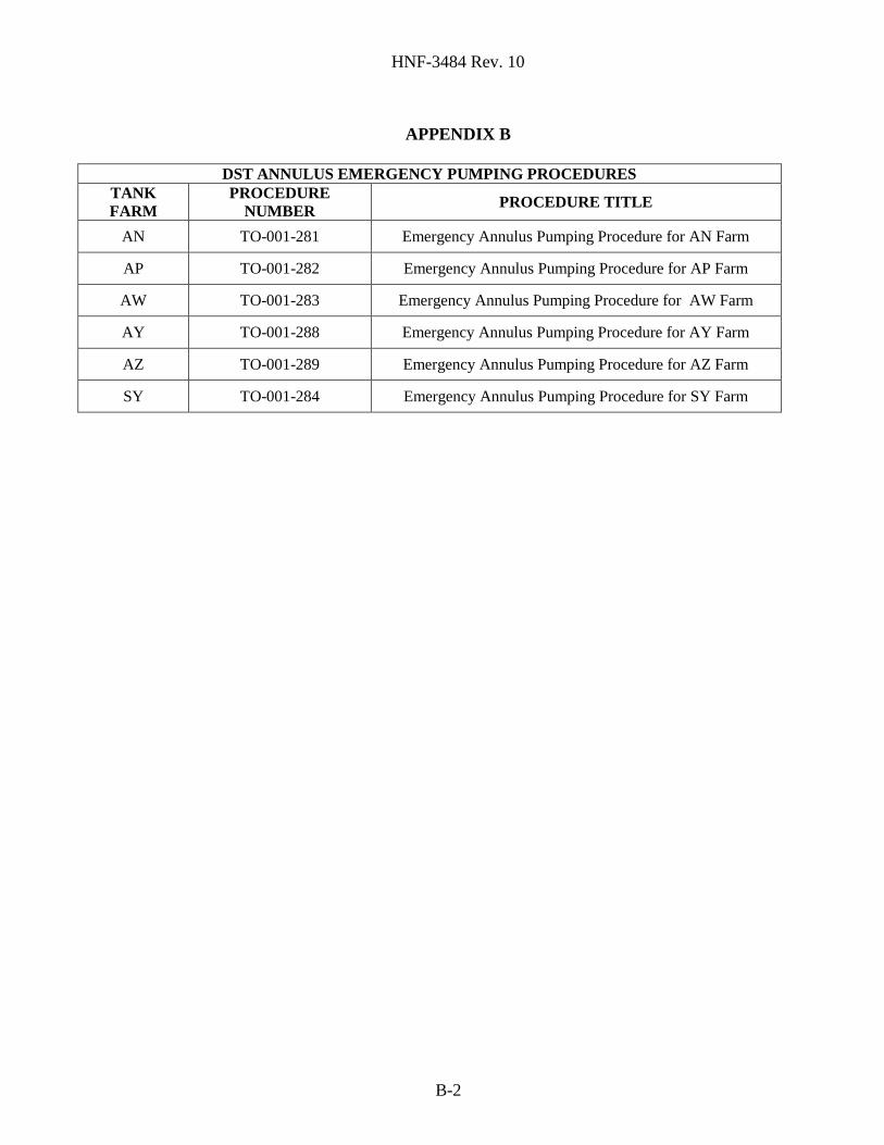
B LIST OF IMPLEMENTING PROCEDURES AND RELEVANT DRAWINGS .. B-1
C IDENTIFICATION AND LOCATION OF DST PUMPS AND JUMPERS
THAT WOULD BE USED FOR EMERGENCY PUMPING ..............................C-1
D CROSS SECTION OF ANNULUS OF DOUBLE-SHELL TANK ..................... D-1
Page 3
HNF-3484 Rev. 10
3
E PROPOSED ANNULUS EMERGENCY PUMPING TRANSFER ROUTES
To DESIGNATED RECEIVER TANK ................................................................ E-1
F APPLICABLE ANNULUS EQUIPMENT ........................................................... F-1
G TRANSFER PIPELINES REQUIRING TESTING PRIOR TO USE…………G-1
H SCHEDULE OF CRITICAL PATH ANNULUS PUMPING ACTIVITIES ....H-1
I SCHEDULE OF CRITICAL PATH PRIMARY TANK SYSTEM PUMPING
ACTIVITIES……………………........……………........……………………….I-1
FIGURES
Figure 1. Double-Shell Tank Piping Diagram 200-East Area……………………………8
Figure 2. Valve Pit Permanent Jumper Configurations…………………………………..9
Figure 3. Annulus Pumping Transfer Route Schematic………………………………...12
Figure 4. Typical DST Configuration…………………………………………………...16
Figure 5. Schematic Diagram of Minor Leak ...................................................................22
Figure 6. Schematic Diagram of Major Leak in Double-Shell Tank ................................23
TERMS
DOE U.S. Department of Energy
DST double-shell tank
Ecology Washington State Department of Ecology
gpm gallons per minute
HTWOS Hanford Tank Waste Operations Simulator
in. inches
mm millimeters
ORP U.S. Department of Energy, Office of River Protection
RCRA Resource Conservation and Recovery Act of 1976
SST single-shell tank
SACS Surveillance Analysis Computer System
TFCOUP Tank Farm Contractor Operation & Utilization Plan
TWINS Tank Waste Information Network System
USQ unreviewed safety question
WTP Hanford Tank Waste Treatment and Immobilization Plant
Page 4
HNF-3484 Rev. 10
4
1.0 GENERAL INFORMATION
1.1 PURPOSE, SCOPE, AND BACKGROUND
The purpose of this plan, HNF-3484, Double-Shell Tank Emergency Pumping Guide, is to
provide as much preplanning as practical for pumping waste out of the primary tank system, and
annulus or secondary containment of double-shell tanks (DST) in the event of a leak. If the
primary tank system leaks, waste would accumulate in the secondary containment. For the
purposes of this plan, the terms "secondary containment" and "annulus" are used
interchangeably. The regulatory requirements applicable to a leaking DST are set forth in
Washington Administrative Code (WAC).
WAC 173-303-640(7) Responses to leaks or spills and disposition of leaking or unfit-for-use
tank system identifies the requirements for dealing with a tank leak. This pumping guide focuses
on item (7)(b), Removal of waste from tank system or secondary containment system. Other
provisions of WAC 173-303-640(7) are addressed in RPP-16922 Environmental Specifications
Requirements. RPP-16922 is the Tank Farm environmental specifications requirements
document which implements environmental-regulatory limits on the configuration and operation
of the Hanford Tank Farms, 242-A Evaporator, Laboratory and related facilities that have been
established by environmental regulations, orders, and agreements. The other provisions of WAC
173-303-640(7) which addressed in RPP-16922 are described below.
(7)(a) Cessation of use; prevent flow or addition of waste – RPP-16922, Section 8.2
requires immediate removal from service of any DST System or secondary containment
system from which there has been a leak or spill.
(7)(b) Removal of waste from tank system or secondary containment system –
RPP-16922, Section 8.2 requires compliance with the strategies and emergency pumping
actions outlined in this Pumping Guide (HNF-3484). Compliance with this requirement
is the primary focus of this Pumping Guide.
(7)(c) Containment of visible releases to the environment - Response to a release outside
of the DST secondary containment is not in the scope of this document, and will be
addressed in RPP-16922.
(7)(d) Notifications, reports - RPP-16922, Section 2.1 identifies the regulatory agency
reporting requirements. Section 8.2 requires the notification of the on-call environmental
representative. The on-call environmental representative determines reportability to
Ecology, WDOH, and EPA in accordance with TFC-ESHQ-ENV_FS-C-01.
(7)(e) Provision of secondary containment, repair, or closure - assessment of tank
conditions at the conclusion of pumping is not in the scope of this document, and is
addressed in RPP-16922.
(7)(f) Certification of major repairs – The issue of major repairs will be dealt with at the
conclusion of pumping and is not in the scope of this document. Section 8.2 of
RPP-16922 requires certification by an independent, qualified, registered, professional
engineer prior to returning the tank system to service if the tank system has had extensive
repair (e.g., installation of an internal liner; repair of a ruptured primary containment or
secondary containment vessel).
Page 5
HNF-3484 Rev. 10
5
There are 177 underground waste storage tanks in the Hanford Site 200 East and 200 West
Areas. There are 149 single-shell tanks (SSTs) and 28 DSTs. The scope of this guide includes
all 28 of the Hanford Site DSTs in AN, AP, AW, AY, AZ and SY Tank Farms. The scope also
includes the transfer lines, pump pits, valve pits, jumpers, transfer pumps, sump pumps, and
procedures necessary to accomplish the emergency pumping. Revision 10 of HNF-3484,
Double-Shell Tank Emergency Pumping Guide, provides additional detail on the pumping of the
primary tank, available tank space for emergency use, and incorporates comments from Ecology.
1.2 DISCUSSION OF SPARE TANK SPACE
In the previous versions of this document two DSTs were identified as spares, one for typical
DST waste and one for aging waste. The identified spare tanks were 241-AP-108 and
241-AY-101, respectively, which roughly provided two-million gallons of tank space. The aging
waste has historically been segregated in the AY and AZ Tank Farms because of the high heat
content of the solids and liquid. The DSTs in the AY and AZ Tank Farms are designed to handle
the higher heat content waste. The current heat content of the liquid in the aging waste tanks has
significantly decreased due to the decay of the short-lived radionuclides. The heat content is low
enough that the liquid can be transferred to a standard DST for storage (Reference Tank Waste
Information Network System [TWINS]). This reduces the need for emergency storage space in
the DSTs to the equivalent of a single tank volume. In addition, contractual and safety
obligations between the Hanford Tank Waste Treatment and Immobilization Plant and DST
Farms have been reconciled to be consistent with the U.S. Department of Energy (DOE)
Order 435.1 to maintain sufficient storage capacity for the largest volume of waste from either
facility. Previously, the DOE Order had been interpreted as requiring simultaneous emergency
capacity for both facilities.
Over the next few years with the accelerated retrieval of waste from the SSTs, tank space will be
dynamic, and at a premium in the DST system. Waste will constantly be moved into the DST
system from SSTs and run through the 242-A Evaporator for concentration. To maximize
available tank space in the DSTs, re-concentration of some of the existing waste and raising the
maximum tank levels is being considered. At any given time in the future, it will not be possible
to keep one single tank empty as a spare for emergency pumping, because of the planned transfer
sequences to evaporate and stage waste.
The plan for emergency pumping is to have 1,265,000 gallons (460 inches) of distributed tank
space available at all times. Maintenance of this emergency distributed tank space will be
controlled utilizing the Hanford Tank Waste Operations Simulator (HTWOS) computer model,
as documented in the HNF-SD-WM-SP-012, Tank Farm Contractor Operations and Utilization
Plan. HTWOS modeling is performed whenever it is required based on a review of all new tank
waste retrieval and supplemental treatment projects and new or complex processes or processes
with potential downstream impacts during the engineering planning process. Waste inventories
are tracked using the Surveillance Analysis Computer System (SACs) which contains real time
tank waste level data and the HNF-EP-0182, Waste Status Summary Report updated monthly.
Previously, Tank 241-AP-108 was identified as the most likely tank to be available for receipt of
waste. However, in April of 2007, Tank 241-AP-108’s available space was utilized when the
tank was filled to approximately 454 inches during efforts to maximize available DST space by
Page 6
HNF-3484 Rev. 10
6
increasing the tanks maximum waste operating level. The AP Tank Farm was selected as the
first tank farm to have the maximum waste level operating limits increased in the DSTs.
Tank 241-AW-105 is now anticipated to be the most likely tank to be available for receipt of
waste based upon the revised operating strategy for AP Tank Farm. There is approximately
725,000 gallons of dedicated space in Tank 241-AW-105 that would be available for emergency
use. If warranted, any additional volume would then be distributed amongst other DSTs that
have space available. All DSTs with space available would be reviewed to determine the best
location for any additional volume that does not fit into tank 241-AW-105. If necessary, multiple
DSTs may be utilized to provide sufficient space.
Tank 241-AW-102 has been selected as the receiver tank for waste in Tank 241-AW-105 if the
subject tank were to leak. Tank 241-AW-102 is typically only full of waste just prior to a 242-A
Evaporator campaign. Tank 241-AW-105 waste may also be distributed amongst multiple DSTs
if Tank 241-AW-102 does not have sufficient space to receive waste from Tank 241-AW-105.
The primary tank system and annulus pump-out operations would not be expected to be delayed
significantly by the use of distributed space. Piping configuration changes to additional tanks are
in many cases performed by valving manipulations. Alternative jumper reconfigurations to other
DST storage locations can primarily be performed simultaneously with ongoing pumping
operations.
The DST transfer system is composed of a series of pipe encased transfer lines connecting each
tank within a tank farm, and a series of transfer lines connecting the six tank farms. Routings
between tanks are accomplished by using removable piping connections (jumpers) in concrete
pits. The W-314 Project has recently modified pits in AN and AW Tank Farms with multi-
valved jumper manifolds that allow transfers between tanks within the tank farms to be made
with simple valving manipulations. A new valve pit was installed in the AZ Tank Farm with
multi-valve jumper manifolds to allow distribution of waste transfers between AN, AP, AW, AY
and AZ Tank Farms. The AP Tank Farm also has this manifold configuration to simplify
transfers. The scope of the W-314 Project was to replace older non-Resource Conservation and
Recovery Act of 1976 (RCRA) compliant transfer piping and to upgrade process pits to meet
RCRA requirements. Other ancillary equipment such as piping jumpers were replaced to
provide additional transfer flexibility. The accelerated retrieval operations at the Hanford Site
are requiring many transfers to be made to the different tank farms. Additional jumper
configurations were installed to facilitate these transfers. These jumper configurations will in
turn make emergency pumping transfers to distributed tank space more efficient. Figure 1 shows
a layout of the DST transfer piping in the 200-East Area. The existing transfer pipelines between
each of the 5 DST farms and between each of the 25 DSTs are shown. Many of the 25 DSTs
contain active transfer pumps in the primary tank. The transfer pipeline configuration and
valved pipe jumpers allow the transfer of waste from any tank to any other tank. Details of the
valved pipe jumper configurations in valve pits are shown in Figure 2 to help illustrate the
capability of rerouting waste from one tank to another.
A leak in the primary tank system in SY Tank Farm is handled by initiating a cross-site transfer
from 200 West Area to available emergency tank space in 200 East Area. Primary tank waste in
Tank 241-SY-101 or Tank 241-SY-102 could be readily transferred to 200 East Area tanks if a
Page 7
HNF-3484 Rev. 10
7
leak develops since these tanks have operable, routinely used pumps in the primary tank system.
Primary tank waste in Tank 241-SY-103 would need to be transferred to either Tank 241-SY-101
or Tank 241-SY-102 which can receive waste and simultaneously transfer to available
emergency tank space in 200 East Area. Any unused tank space in SY Tank Farm may be
utilized as available distributed emergency tank space.
1.3 DISCUSSION OF INCREASING TANK LEVEL
The Tank Farm Contractor is in the process of reevaluating the DST tank level operating limit to
potentially increase waste storage space in response to Hanford Federal Facility Agreement and
Consent Order (HFFACO) milestones M-45-00, M-46-21, and the projected start of the Hanford
Tank Waste Treatment and Immobilization Plant. The design (structurally analyzed) limit for
the majority of the DSTs is currently 422 inches with an operating limit of 416 inches (1.14
million gallons). The maximum analyzed limit for 241-AP Tank Farms will be increased to 460
inches with a maximum operating limit of 454 inches (once an in-service leak test has been
successfully completed). Discussion and the technical basis for the increased DST tank level is
contained in Operating Specification Document OSD-T-151-00007. Once each tank in AP Tank
Farm successfully passes an in-service leak test, each tank will be capable of storing an
additional 86,500 gallons of waste. This additional space will be factored into the distributed
spare tank space as required by this plan. Structural evaluations and operational controls during
the increased fill have been recommended by an Expert Panel and documented in RPP-19438,
Report of Expert Panel Workshop for Hanford Site Double-Shell Tank Waste Level Increase.
Contingency planning will ensure the response to a leak is handled in a safe and efficient
manner. A contingency procedure will be developed to pump down the tank being filled if a leak
occurs. The procedure would include verification of an operable pump in the primary receiving
tank with a contingency piping route established to a tank. In the case of a DST to DST transfer
only minor changes in valving would be needed to reverse the route back to the sending tank.
The only tanks planned for the increased level at this time will be in the AP Tank Farm and will
receive evaporator slurry. In this case, a contingency route from the slurry receiver to
Tank 241-AW-102 or an alternate tank in 241-AW Tank Farm will be established in advance. A
waste compatibility report will be issued in advance as well for the contingency transfers. Any
pumping operation would be stopped immediately upon detection of a leak. The intent is to
commence the contingency transfer immediately upon detection of a leak, pump down to the
historic operating level and remain in service. The historic operating level will be identified
using the data from SACS. Removal of any waste from the annulus would be accomplished in
accordance with the guidance outlined in this document.
Page 8
HNF-3484 Rev. 10
8
FIGURE 1
Double-Shell Tank Piping Diagram – 200-East Area
241-AP Tank Farm
241-AW-A
Valve Pit
241-AW-B
Valve Pit
241-AP Valve Pit
241-AW Tank Farm
Page 9
HNF-3484 Rev. 10
9
Page 10
HNF-3484 Rev. 10
10
Page 11
HNF-3484 Rev. 10
11
1.4 NON-COMPLIANT TRANSFER LINES FOR EMERGENCY USE
Replacement transfer pipe lines are not being installed in the SY Tank Farm to replace non-RCRA
compliant pipe lines. The non-compliant transfer lines have encasements that do not penetrate the
pit walls. Upgrades to existing pipe lines supporting transfers from the SY Tanks are being deferred
due to lack of planned transfers in the next five to ten years. In the event that an unexpected
transfer (e.g., primary or annulus transfer) is required from these tanks, the non-compliant pipe lines
will be used. A variance letter (Ecology letter April 13, 2004) provides approval for using ten non-
compliant pipe lines if several conditions are met. These transfer pipelines are identified in
Appendix G.
Several transfer lines from the annulus pump pits to the central pump pits are not encased or not
fully encased in the older DST Tank Farms (AY, AZ & SY). Ecology concurred with future use of
emergency pump-out lines from the annulus pump pits to the central pump pits, which are
considered part of secondary containment (Ecology letter January 14, 2003). This emergency
pumping guide includes the planned use of annulus pump pit secondary containment transfer lines.
A listing of these transfer pipelines is in Appendix G.
A number of compliant transfer pipelines do not have an anticipated use for the next five to ten
years. Pressure testing of these pipeline encasements was not performed as part of the integrity
assessment program due to the low probability of need. The encasement pressure testing of these
seventeen transfer pipelines will be delayed and these pipelines will be listed in the DST Integrity
Assessment Report as out-of service pending a pressure test (DOE Letter 05-TED-093). In the
unlikely event of a DST leak, these pipelines will have an expedited secondary pipeline
(encasement) pressure test and independent, qualified, registered, professional engineer approval
prior to use. Eight of these transfer pipelines are identified in this document as necessary for
emergency pumping. A listing of these transfer pipelines is in Appendix G.
One additional transfer pipeline does not have the encasement pressure testing completed. This
pipeline will be listed in the DST Integrity Assessment Report as out-of service pending a pressure
test. This transfer pipeline is listed in Appendix G.
Pressure testing will be performed for any variance and emergency use only transfer pipelines prior
to use to verify integrity. Any pipelines that have not had the secondary pipeline (encasement)
pressure tested as required in the integrity assessment report will be tested prior to use. In the event
of a failed pressure test, an alternate piping route will be identified. This pumping guide primarily
identifies the use of supernate transfer pipelines in the tank farms. These supernate transfer
pipelines are normally three-inch diameter pipelines used for transferring the more dilute wastes. In
most cases a parallel, redundant transfer pipeline to the supernate exists. This alternate is referred
to as the slurry pipeline. The slurry piping is typically two-inch diameter and used for transferring
the more concentrated waste. Piping jumper connection changes in the central pump pits or valve
pits would be required to change configuration from the supernate to slurry piping. Spare flexible
jumpers identified in Appendix F would be used for this purpose. Pressure testing of the Slurry
piping encasement, as required in the integrity assessment report, will be performed prior to use.
Alternative route/methods may include but not be limited to the use of Hose-in-Hose Transfer Lines
or repair and/or retesting of supernate and/or slurry transfer line. Refer to Figure 3 for an example
of the proposed transfer route from Tank 241-AN-101 to Tank 241-AW-105.
Page 12
HNF-3484 Rev. 10
12
Page 13
HNF-3484 Rev. 10
13
1.5 NON-COMPLIANT PROCESS PITS FOR EMERGENCY USE
The annulus pump pits are considered Emergency Use Components as discussed in Ecology Letter
January 14, 2003. These annulus pits will maintain an operational leak detection system and drain
to a DST as committed in the January 14, 2003 Ecology Letter. One process pit required for
emergency pumping of 241-SY-01A does not yet have a specifically defined future mission. The
241-SY-01A Pit is unique in that it has a mixer pump with a significant amount of support
equipment on the top of the pit cover which would require removal to allow a jumper installation.
In this case the annulus pumping plan bypasses the 241-SY-01A Pit with an overground transfer
line from the annulus pump pit directly to the prefabricated pump pit. This process pit will also
maintain an operational leak detection system and drain to a DST.
1.6 SUMMARY OF INFORMATION PROVIDED
This guide contains a general description of the DSTs and discussions of the requirements, strategy,
transfer routes, procedures, and equipment that will be used to expeditiously respond to a leaking
DST. References to statutory requirements are included. The Authorization Basis requirements for
DST Emergency Pumping are implemented through operating procedures and work packages.
Information for each DST about the waste transfer routes, procedures, and equipment required for
the transfers are contained or referenced in the appendices. These include:
Appendix A: PROPOSED PRIMARY TANK TRANSFER ROUTES
Contains a tabulated summary description of a proposed transfer route for each DST. Routes are
included for transferring the waste from the primary tank to the designated receiver tank.
Tank 241-AW-105 is the selected designated receiver tank for emergency transfers from all DSTs
for this document. The alternate receiver tank for Tank 241-AW-105 is Tank 241-AW-102. Other
or multiple tanks in the DST system may be utilized for emergency annulus pumping operations.
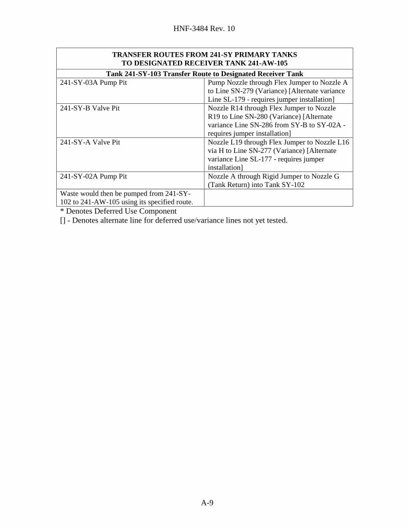
The receiver tank for Tank 241-SY-103 is Tank 241-AW-105 via Tank 241-SY-102. Since the
DST space is so dynamic, alternate routings to any of the six DST farms may be utilized for annulus
emergency pumping. Transfer routes that utilize deferred use and variance transfer lines also list an
alternate line (when available). Refer to Figure 3 for an example of the proposed transfer route
from Tank 241-AN-101 to Tank 241-AW-105.
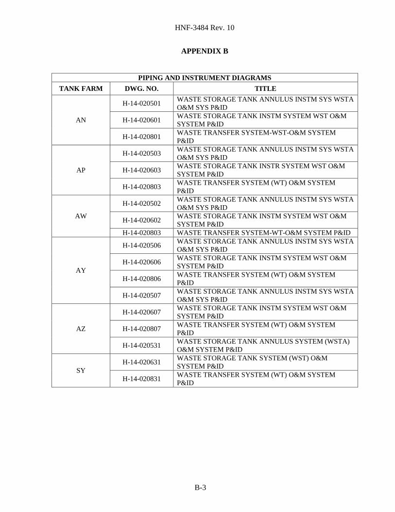
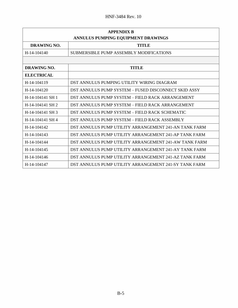
Appendix B: IMPLEMENTING PROCEDURES AND RELEVANT INFORMATION
Contains a list of applicable transfer operating procedures, a list of Piping and Instrumentation
Drawings (P&ID) for each DST farm, and a listing of design/fabrication/installation drawings for
the annulus pumping equipment.
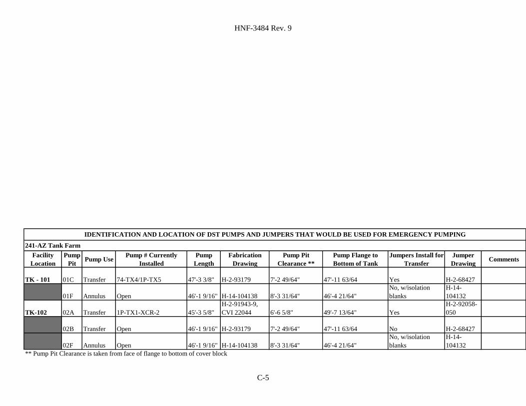
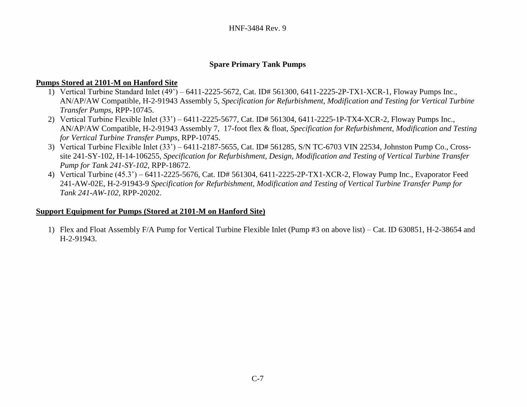
Appendix C: INVENTORY AND STATUS OF REQUIRED EQUIPMENT
Contains a list of equipment that would be used to transfer waste out of a leaking DST primary tank
system. This list includes spare primary vertical turbine pumps. If any of these pumps are utilized
for operations other than annulus pumping, they must be replaced as soon as possible by the
organization that utilizes the spare.
Page 14
HNF-3484 Rev. 10
14
Appendix D: CROSS SECTION OF ANNULUS OF DOUBLE-SHELL TANK
Contains a sketch of a cross section of the bottom of a typical DST, a list of assumptions, and a
table of the volume of liquid that would be present in the annulus at various depths.
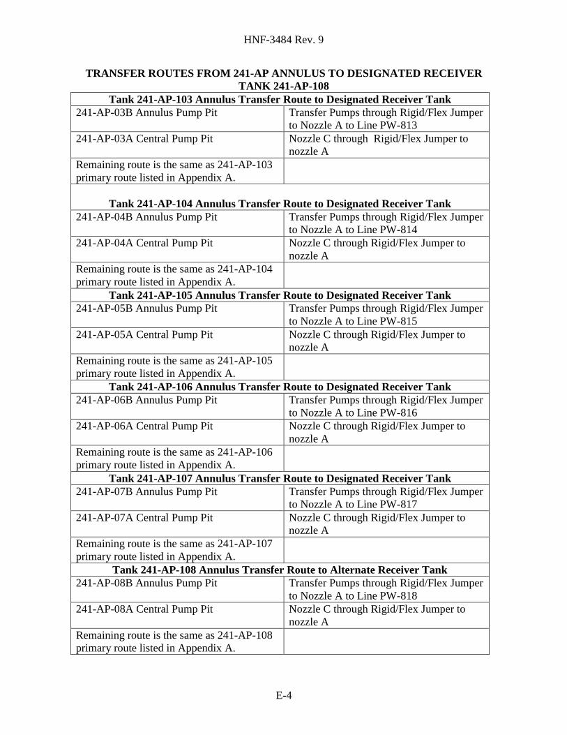
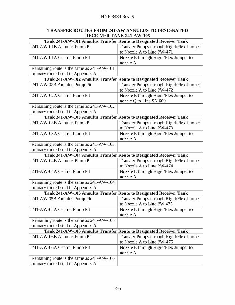
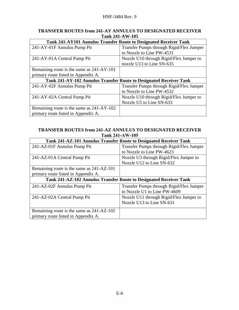
Appendix E: ANNULUS PUMPING ROUTES
Contains a tabulated summary description of a proposed transfer route for each DST annulus.
Routes are included for transferring the waste from the annulus to the designated receiver tank.
Tank 241-AW-105 is the selected designated receiver tank for emergency annulus transfers from all
DSTs for this document. The alternate receiver tank for Tank 241-AW-105 is Tank 241-AW-102.
Other or multiple tanks in the DST system may be utilized for emergency annulus pumping
operations. The receiver tank for Tank 241-SY-103 is Tank 241-AW-105 via Tank 241-SY-102.
Since the DST space is so dynamic, alternate routings to any of the six DST farms may be utilized.
A table of available annulus pumping risers is also included. Transfer routes that utilize deferred
use and variance transfer lines also list an alternate line (when available). Refer to Figure 3 for an
example of the proposed transfer route from Tank 241-AN-101 to Tank 241-AW-105.
Appendix F: APPLICABLE ANNULUS EQUIPMENT
Contains lists of applicable annulus equipment and storage locations. This equipment includes six
flex jumpers, components for two complete rigid jumpers, four submersible pumps, two
reciprocating pumps, components for pump assemblies, and a skid for air and electrical support
equipment.
Appendix G: TRANSFER PIPELINES REQUIRING TESTING PRIOR TO USE
Contains a table of transfer pipelines primarily in SY Tank Farm that have a physical configuration
which does not fully comply with the requirements or interpretations of WAC 173-303. The
encasements of these pipelines do not extend through the one-foot thick pit concrete wall. These
pipelines will be operated in their existing configuration utilizing the agreed upon compensatory
requirements, and are referred as variance components. The appendix also contains a table of
pipelines, which will be used only in the case of an accident or emergency. Some of the
components in this table do not fully comply with WAC-173-303. The transfer pipelines are
located between the annulus pump pits and the central pump pits and are referred to as emergency
use components. The final table is a listing of transfer pipelines that are not intended to be used for
over 5 years and have not been pressure tested and certified by an integrity assessment.
Appendix H: SCHEDULE OF ANNULUS PUMPING ACTIVITIES
Contains the critical path schedule of activities required to support annulus pumping developed for
reference RPP-5842. Appendix H includes pressure testing of the annulus transfer lines identified
in RPP-5842 Appendix B within the initial ten day response period. Additional time to prepare and
pressure test an alternative transfer line will be required in the event that a noncompliant transfer
line identified for use fails it is pressure test. Each identification and testing of lines is based on a
ten day period which would begin at the time the previously identified transfer line failed its
pressure test. The risk of failure for the noncompliant lines in the DST system has been determined
Page 15
HNF-3484 Rev. 10
15
to be low based upon historical evidence and recent pressure test data from various DST system
buried transfer lines. This risk is considered acceptable to protect health and the environment.
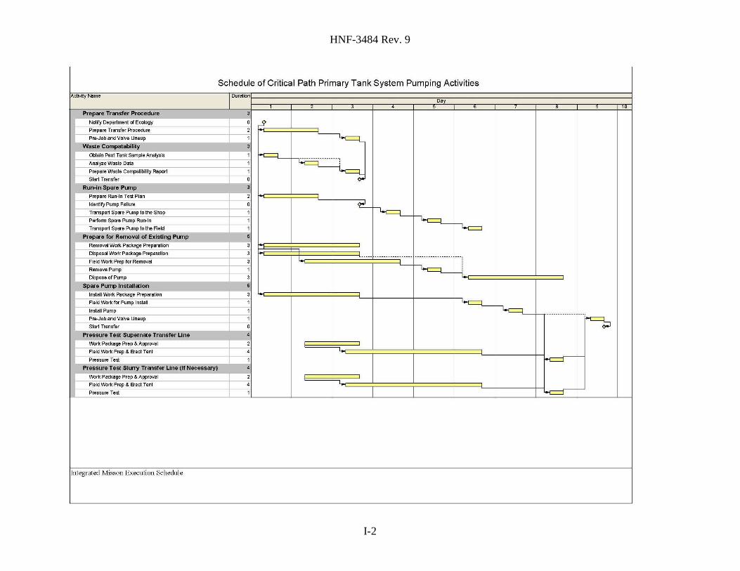
Appendix I: SCHEDULE OF PRIMARY TANK SYSTEM PUMPING ACTIVITIES
Contains the critical path schedule of activities required to support primary tank system pumping.
In the event that a noncompliant transfer line identified for use fails its pressure test, additional time
to prepare and pressure test an alternative transfer line will be required. Each identification and
testing of lines is based on a ten day period which would begin at the time the previously identified
transfer line failed its pressure test.
2.0 EQUIPMENT DESCRIPTION
All DSTs are similar in design and each has a capacity of approximately 3.8 to 4.8 million liters
(1 to 1.26 million gal) (see Figure 4). Slight differences in the tank and ancillary equipment,
however, have occurred over the years from design improvements and because of the need to
accommodate variations in waste composition. Twenty-eight DSTs are located in six farms, five
farms in 200 East Area and one farm in 200 West Area. DSTs consist of a carbon steel primary
tank system and a carbon steel secondary containment encased by a protective reinforced concrete
shell. The tanks contain a mixture of liquid, sludge, and saltcake waste with both radioactive and
chemically toxic hazardous constituents. Liquids exist as supernate (liquid above solids) and
interstitial liquid (liquid filling the voids between solids) in the tanks. Sludge consists primarily of
solids (hydrous metal oxides) precipitated by the neutralization of acid wastes. Saltcake, generally
between the supernate and sludge, consists of the various salts formed by the evaporation of water
from the waste. These waste types do not necessarily exist as distinct layers and may be
intermingled to differing degrees. Some sludges and saltcakes contain interstitial liquid and are
relatively soft; others may be drier and harder.
Each tank is equipped with riser pipes that penetrate the concrete dome and the top of the primary
tank system or secondary containment. The risers provide access to the primary tank system and to
the annulus space for waste transfer operations or equipment installation for monitoring. Most
risers extend above grade. However, some risers are located under covered pits (e.g., Central Pump
Pits and Annulus Pump Pits).
Pits provide access from the surface to process piping and tank risers and are the points where
jumpers (temporary piping systems), pumps, and other equipment are installed to establish waste
transfer routes. A rigid jumper is a steel pipe that is fitted to specific wall nozzle configurations.
The flexible jumpers are braided, stainless steel, flexible hose that permit connections to multiple
wall nozzles.
Page 16
HNF-3484 Rev. 10
16
There are three types of pumps used at the tank farms to transfer waste into and out of DSTs. These
types are (1) jet pumps in combination with centrifugal pumps, with nominal capacities of 0.05 to
4.0 gpm; (2) submersible pumps, with nominal capacities of 10 to 30 gpm; and (3) transfer pumps,
with nominal capacities of 100 to 250 gpm.
The components of a jet pump system located within a pump pit are a centrifugal pump, flexible
or rigid jumpers, a flush line, and a flow totalizer. The centrifugal pump supplies motive fluid
to the submerged jet pump system. Jet pumps are used to move liquid at very low rates.
A submersible pump can be used to raise large volumes of supernatant. The pump motor is
below the pump intake and is submersed in the liquid being pumped.
Transfer pumps are typically installed in a pump pit, with the motor located in the pit and the
intake located in the tank waste. Transfer pumps are normally deep-well, vertical turbine
pumps, where the pump intake is a rigid pipe that extends to a fixed depth in the tank waste.
Some transfer pumps have a floating intake, which is a flexible jumper connected to rigid pipe
that does not extend into the waste.
Figure 4 – Typical DST Configuration
Central Pump Pit
Vertical Turbine Pumps
Submersible
Annulus Pump Pit
Grade
Rigid Jumpers
Encased Transfer lines
Primary
Secondary
2.1 PRIMARY TANK PIT CONFIGURATION
All DSTs have a Central Pump Pit, which is approximately centered over the primary tank. The
primary function of the pit is to provide confinement for a possible spray leak during waste transfers
and to provide radiation shielding during waste transfers. The Central Pump Pits provide for access
to the tank for supernatant filling or removal, slurry distribution, and mixing. Supernatant filling is
accomplished though piping or jumpers connected to the riser. For supernatant removal, Central
Pump Pits are designed to hold a deep-well turbine pump and piping jumpers. Central Pump Pits
for receiver tanks that store slurry are equipped with slurry distributors. The jumpers installed in
the Central Pump Pit are either rigid or flexible jumpers. Transfer or submersible pumps are
Page 17
HNF-3484 Rev. 10
17
normally used to remove large volumes of supernatant. Jet pumps would be used to remove
interstitial liquid because the liquid drains out of the sludge interstices too slowly to employ the
transfer pumps. Before a jet pump system can be used to pump interstitial liquid, a stainless steel,
salt screen must be installed in the waste to prevent solids from plugging the jet intakes.
2.2 SECONDARY CONTAINMENT PIT CONFIGURATION
The Annulus Pump Pit is located directly above the annulus and is connected to the annulus by a
riser. The pit and riser provide access for pumping out any liquids that may accumulate in the
annulus.
In the Annulus Pump Pit a rigid or flex jumper assembly connects the annulus pump outlet to a
51-mm (2-in.) waste transfer line enclosed in a 102-mm (4-in.) encasement. The encasement drains
to the Annulus Pump Pit. The waste transfer line terminates at the Central Pump Pit of the tank.
The two AY and AZ tanks have an additional route back to the primary tank via a waste transfer
route from the Annulus Pump Pit to a riser, which connects directly to the primary tank.
2.3 SUPPORT SYSTEMS
Virtually all of the equipment and support systems that would be used for the emergency pumping
of DSTs exist and are in nominal serviceable condition. Appendix C identifies the current pumps
installed in the primary tank systems, and the available ready spares. The spare pumps for the
primary tank systems (Appendix C) include a full length (49-foot) pump that can be used in a tank
with little or no solids. A (33-foot) pump with a flexible end connection to a float can be used for
tanks with significant inventories of solids. The above two pumps were designed for either AN, AP
or AW Tank Farms, and an adapter plate (H-14-107382) can be used for installations in AY and AZ
Tank Farms. A spare cross-site transfer pump is also available for the SY Tank Farm. Submersible
pumps and other emergency equipment for use in annulus pumping will be stored in HO-64-07008,
which is an enclosed portable trailer. Flex jumpers to be used will be stored in the 2101-M
Warehouse. This equipment will be maintained per the Preventative Maintenance System (PMS)
using data sheets. The following data sheets have been developed for the PMS to provide
maintenance of the pumps ET-7459, ET-7460, ET-7666, and ET-7667. Procedure OTP-001-001,
"Operational Test Procedure for DST Annulus Emergency Pumping Equipment,” will be used to
test the pump performance prior to installation.
For Additional information on the Emergency Pumping Equipment see references below:
DST Annulus Pumping Acceptance Test Report (RPP-6638)
Technical Information to Support DST Emergency Annulus Pumping (RPP-6485)
DST Annulus Pumping Acceptance Test Report Supplement (RPP-7919)
System Design Description for Tank Farms Double-Shell Tank Emergency Annulus Pumping
Systems (RPP-15146)
Double Shell Tank Annulus Pumping Vendor Information File (VI-50121)
Page 18
HNF-3484 Rev. 10
18
3.0 PLAN OF ACTION
3.1 REGULATORY REQUIREMENTS APPLICABLE TO LEAKING DOUBLE-SHELL
TANKS
Title 40, Code of Federal Regulations, Part 265.193, “Containment and Detection of Releases”
(40 CFR 265.193)
"…sloped or otherwise designed or operated to drain and remove liquids resulting from leaks, spills
or precipitation. Spilled or leaked waste and accumulated precipitation must be removed from the
secondary containment system within 24 hours, or in as timely a manner as is possible to prevent
harm to human health or the environment, if removal of the released waste or accumulated
precipitation cannot be accomplished within 24 hours."
Washington Administrative Code (WAC) 173-303-640, “Tank Systems”
"…sloped or otherwise designed or operated to drain and remove liquids resulting from leaks, spills,
or precipitation. Spilled or leaked waste and accumulated precipitation must be removed from the
secondary containment system within twenty-four hours, or in as timely a manner as is possible to
prevent harm to human health and the environment, if the owner or operator can demonstrate to the
department that removal of the released waste or accumulated precipitation cannot be accomplished
within twenty-four hours."
DOE 435.1, Radioactive Waste Management, U.S. Department of Energy, Washington, D.C.,
Part II, Section H
H. Contingency Actions. The following requirements are in addition to those in Chapter I of this
Manual.
(1) Contingency Storage: For off-normal or emergency situations involving high-level waste
storage or treatment, spare capacity with adequate capabilities shall be maintained to receive the
largest volume of waste contained in any one storage vessel, pretreatment facility, or treatment
facility. Tanks or other facilities that are designated for high-level waste contingency storage shall
be maintained in an operational condition when waste is present and shall meet all the requirements
of DOE O 435.1, Radioactive Waste Management, and this manual.
(2) Transfer Equipment: Pipelines and auxiliary facilities necessary for the transfer of waste to
contingency storage shall be maintained in an operational condition when waste is present and shall
meet the requirements of DOE O 435.1, Radioactive Waste Management, and this manual.
Ecology Letter January 14, 2003
This letter addresses non-compliant components, which are used only in the case of an accident or
emergency. The components in the listing contained in the letter have a physical configuration that
does not fully comply with the requirements or interpretation of WAC 173-303. The primary issue
covered is the annulus pump-out pits and their transfer lines running to the central pump pit of the
tank.
Page 19
HNF-3484 Rev. 10
19
Ecology Letter April 13, 2004
Upgrades to existing pipe lines supporting transfers from the SY Tanks are being deferred due to
lack of planned transfers in the next 5 to 10 years. In the event that an unexpected transfer (e.g.,
primary or annulus transfer) is required from these tanks, the non-compliant pipe lines will be used.
This variance letter provides approval for using ten non-compliant pipe lines, provided that several
conditions are met.
3.2 GENERAL STRATEGY
The general strategy for responding to a leaking DST is to take the appropriate actions to
immediately remove leaked waste, minimize additional leakage and ensure containment to prevent
harm to human health or the environment. Document RPP-5842, Time Deployment Study for
Annulus Pumping estimates that approximately ten days will be required to initiate annulus
pumping. A schedule of activities is provided in Appendix H. During the ten day period required
for equipment assembly, transfer line pressure testing, transfer pump run-in and preparation of work
and transfer documentation, considerations will be given to methods to minimize leakage. Primary
tank pumping as discussed in Section 3.3 Potential Leak Scenarios could in many cases be initiated
quickly within several days, since pumps and piping routes are available. A schedule of the primary
tank system pumping activities is presented in Appendix I. This parallel pumping effort of the
primary tank would be initiated simultaneously with the annulus pumping activities. The goal of
pumping the primary tank would be to lower the liquid level below that of the leak. A video camera
lowered through one of the many annulus risers will be used to identify the leak location.
The HNF-SD-WM-SP-012, Tank Farm Contractor Operation & Utilization Plan (TFCOUP)
documents the available and projected emergency space allocation as determined by the HTWOS
computer model. Tank space is planned and tracked through the HTWOS computer model to
assure a minimum of 1.265 million gallons of emergency storage capacity is available prior to any
transfer. This volume is the largest amount planned for storage in any one DST as discussed in
Section 1.3. The use of distributed tank space is discussed in Section 1.2. There are several
categories of restricted tank space maintained in reserve in the HTWOS computer model not
planned to be used for storage purposes. One of the categories is “Restricted Transuranic (TRU)
Space” another “Evaporator Operational Space”. The Restricted TRU Space and Evaporator
Operational Space would also be considered for use in an emergency situation such as a tank leak.
Traditional vertical turbine pumps will be used for pumping the primary tank system. A
submersible pump will be used for pumping in the secondary containment. Alternate pumping
strategies were evaluated in document HNF-4241, Double-Shell Tank Annulus Pumping Alternative
Evaluation, Rev. 0. The general strategy for emergency pumping a leaking DST is based on several
assumptions. The more significant assumptions are:
Tank 241-AW-105 is used as an example receiver tank in this document and supporting
procedures. The procedural documentation illustrates the method that will be used to respond to
an emergency transfer. Transfers to the distributed space in any of the other DSTs would
be performed using the same type of documentation, equipment and controls.
Page 20
HNF-3484 Rev. 10
20
Waste compatibility will need to be addressed, but is not expected to be an issue that causes a
delay in the pumping. Reserve tank space equivalent to the maximum volume of a tank is
dedicated for “Emergency Use” and will not be used for operational purposes. Several
categories of additional reserve tank space are restricted from use for storage. This includes
“Evaporator Operational Space” and “Restricted TRU Head Space”, which will be considered
for use in an emergency situation such as a tank leak. The additional reserve tank space should
make the resolution of waste compatibility issues easier. The waste composition for the
material in the sending and receiving tanks will be obtained from the Best-Basis Inventory
(BBI) TWINS, “Tank Waste Information Network System,”
https://twinsweb.pnl.gov/twinsdata/default.htm.
To the maximum extent possible, existing double-contained, underground transfer lines will be
used.
Existing transfer pumps in the DST central pump pits will be used to pump waste out of the
primary tank.
A DST leak in the 241-SY Tank Farm could be pumped to either Tank 241-SY-101 or
Tank 241-SY-102 for transfer to the 200 East Area DSTs. The transfer pumps in these two
primary tanks have the capacity to transfer between the 200 West and 200 East Area.
About six inches of liquid would need to accumulate in the bottom of the annulus before the
submersible pump would automatically prime upon starting.
Each DST annulus has a probe installed that is set to alarm if liquid is detected within the
annulus.
Each DST annulus has at least one probe installed that could be used to monitor liquid level in
the annulus.
A pumping strategy plans to use submersible pumps in all annulus locations (HNF-4241).
Construction Projects at times may interrupt ability to transfer through proposed routings in
Appendix A and Appendix E. Upon detection of a DST leak, restoration of the affected routing
or use of an alternate routing will receive the highest priority and maximum appropriate
resources available to the Tank Farm Contractor.
3.3 POTENTIAL LEAK SCENARIOS
The best strategy for emergency pumping of a specific DST to "prevent harm to human health and
the environment" will depend upon the rate or size of leak from the primary tank. For purposes of
this plan, leak scenarios are divided into three classes based upon the rate of the leak. The Minor
Leak is treated separately because pumpable quantities of waste are likely to be slow to accumulate.
Moderate and Major Leaks are treated together because the emergency response to them would be
the same in either case. In all three scenarios, measures will be taken to identify the location of the
leak point. Visual inspection of the annulus would be performed using a remote video camera
mounted on a hand-held wand or using a remote video camera mounted on a robot similar to ones
used for tank integrity assessments to determine location and elevation of leak. Many risers are
available around the perimeter of the annulus for leak observation.
Use of the video camera to inspect the DST annulus region, as described below, will also be utilized
when the other 241-AP DSTs are initially re-rated for use at the increased maximum waste
Page 21
HNF-3484 Rev. 10
21
operating level. It should be noted that the scenario below is also being provided to illustrate
methods that may be utilized to identify the primary tank leak location in the event a leak were to
occur.
Video cameras were allocated for the four quadrant annulus surveillance activity and spare cameras
were available on site. Nearly 360° coverage of the exterior of the primary tank could be inspected
via access in ten different open risers during DST level rise activities in Tank 241-AP-108. Once
the leak location is identified on the exterior of the primary tank, the length of the cable compared
to the known riser elevation can be used to estimate the leak position. The circumferential welds
joining each course may also be compared to the as-built facility drawings when determining the
approximate location of the leak point. This method was utilized when monitoring of the crack-like
indication region was performed during DST level rise activities in Tank 241-AP-108.
Monitoring of the waste level in the primary tank during pumping operations will also be used to
determine the proximity to elevation of leak path on the sidewall or bottom of the primary tank.
The accuracy of the material balance readings is impacted by the accuracy of the tank level
instrumentation in the sending and receiving tanks, transfer route line hold-up volumes, and
potentially tank waste characteristics (e.g., gas retention, solids, etc.). Level instrumentation
accuracy varies from ± 0. 1 inches (ENRAF) to ± 0.25 inches (Manual Tape). The material balance
trend will be monitored periodically while waste is transferred out of the primary tank. As long as
waste continues to leak into the annulus, the material balance is anticipated to continue to trend
negative. This trend should stabilize once the leak point is reached. However, it is recognized that
other factors influence the material balance trend. That is why this method should be utilized in
conjunction with a video inspection of the annulus to ascertain the exact location of the leak point.
Pumping of the primary tank should continue until the waste level is sufficiently below the leak
path to stop the leak. Once a leak has been identified, all transfers of waste into the leaking tank are
terminated and the tank is considered out of service until repaired or replaced. During the
emergency response period waste will be pumped to below the leak point to allow for inspection of
the primary tank. Waste may remain in the tank below the leak point in compliance with
WAC 173-303-640(7)(b)(i). This strategy allows for the maintenance of emergency space with in
the DST system in an environmentally protective manner. The strategies in this section describe the
emergency actions to stop the leak and reduce harm to human health and the environment.
Traditional vertical turbine pumps will be used for pumping the primary tank system. A submersible
pump will be used for pumping in the secondary containment. Alternate pumping strategies were
evaluated in HNF-4241. A submersible pump will be installed 2.5 inches above the bottom of the
secondary containment. This will allow for pumping of the waste to within approximately 6 inches
of the bottom of the tank. About 2,193 gallons of residual waste would remain in the annulus (see
Appendix D). An air pump will also be installed to within 2.5 inches of the bottom of the secondary
containment and would be capable of pumping to within approximately three inches of the bottom
of the tank. Assuming there is no absorption of waste in the insulating concrete, about 3,900 liters
(1,030 gallons) of residual waste will remain in the annulus (see Appendix D). Repeated water
flushing could be used as a method to remove the residual waste. Any moisture from the
unpumpable residue would be evaporated by the high-efficiency particulate air filtered annulus
ventilation system.
Page 22
HNF-3484 Rev. 10
22
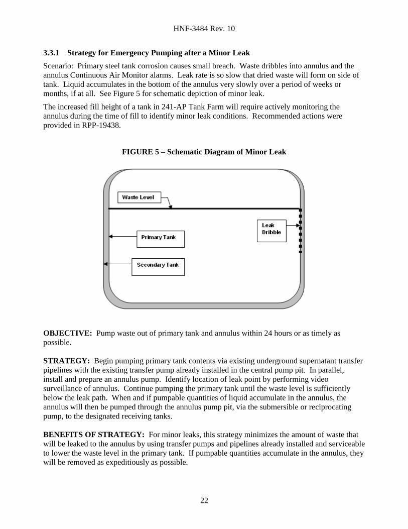
3.3.1 Strategy for Emergency Pumping after a Minor Leak
Scenario: Primary steel tank corrosion causes small breach. Waste dribbles into annulus and the
annulus Continuous Air Monitor alarms. Leak rate is so slow that dried waste will form on side of
tank. Liquid accumulates in the bottom of the annulus very slowly over a period of weeks or
months, if at all. See Figure 5 for schematic depiction of minor leak.
The increased fill height of a tank in 241-AP Tank Farm will require actively monitoring the
annulus during the time of fill to identify minor leak conditions. Recommended actions were
provided in RPP-19438.
FIGURE 5 – Schematic Diagram of Minor Leak
OBJECTIVE: Pump waste out of primary tank and annulus within 24 hours or as timely as
possible.
STRATEGY: Begin pumping primary tank contents via existing underground supernatant transfer
pipelines with the existing transfer pump already installed in the central pump pit. In parallel,
install and prepare an annulus pump. Identify location of leak point by performing video
surveillance of annulus. Continue pumping the primary tank until the waste level is sufficiently
below the leak path. When and if pumpable quantities of liquid accumulate in the annulus, the
annulus will then be pumped through the annulus pump pit, via the submersible or reciprocating
pump, to the designated receiving tanks.
BENEFITS OF STRATEGY: For minor leaks, this strategy minimizes the amount of waste that
will be leaked to the annulus by using transfer pumps and pipelines already installed and serviceable
to lower the waste level in the primary tank. If pumpable quantities accumulate in the annulus, they
will be removed as expeditiously as possible.
Page 23
HNF-3484 Rev. 10
23
Once the primary tank waste level has been lowered below the leak path and any pumpable
quantities of waste in the annulus are removed, the emergency nature of the transfers can be
downgraded and a permanent resolution determined. Removing as much of the waste as possible in
a non-emergency mode is more likely to prevent harm to human health or the environment than
pumping all of the tank's contents in an emergency mode.
3.3.2 Strategy for Emergency Pumping after a Moderate or Major Leak
Scenario: A moderate or major leak occurs in the primary steel tank somewhere below the waste
level. The waste levels in the primary tank system and secondary containment equilibrate within
hours or days. See Figure 6 for schematic depiction of a moderate to major leak.
FIGURE 6 – Schematic Diagram of Major Leak in Double-Shell Tank
OBJECTIVE: Pump waste out of primary tank and annulus within 24 hours or as timely as
possible.
STRATEGY: Begin pumping primary tank via existing underground supernatant transfer pipelines
with the transfer pump installed in the leaking tank's central pump pit. Identify location of leak
point by performing video surveillance of annulus. Continue pumping the primary tank until the
waste level is sufficiently below the leak path. In parallel with pumping of the primary tank, install
and prepare annulus pump. Monitoring and controlling the waste level in the annulus with respect
to the waste level in the primary tank is important to prevent buoyant forces from floating the
primary tank.
Once the primary tank waste level has been lowered below the leak path, begin pumping waste from
the annulus via existing underground transfer lines from the annulus pump pit to the central pump
pit. From the central pump pit, the route would be jumpered to the same route used for transferring
waste from the primary tank to the designated receiver tanks.
Page 24
HNF-3484 Rev. 10
24
BENEFITS TO STRATEGY: Most DSTs have primary transfer pumps installed. This strategy
uses transfer pumps and pipelines already installed and serviceable so that pumping could be
initiated more quickly. The leak will be stabilized faster and the portion of the annulus above the
leak path will be pumped faster by using the higher capacity primary tank transfer pump than by
using the annulus pump.
The waste in the annulus would be pumped to the designated receiver tank via the established
transfer route as necessary. Once the location of the leak is determined and the annulus is pumped,
the emergency nature of the transfer could be downgraded. The waste remaining in the non-leaking
portion of the tank could be left in the tank or pumped to some other tank, depending upon the best
solution under the circumstances. Removing as much of the waste as possible in a non-emergency
mode is more likely to prevent harm to human health or the environment than pumping all of the
tanks contents in an emergency mode.
If the leak path is near the bottom of the tank, then this approach will result in removing waste from
the annulus in the most timely manner because the highest capacity pump and transfer routes are
employed. The annulus level will equalize with the primary tank level and have a volume reduction
as the primary is pumped.
Because the primary tank pumping and annulus pumping use a common route to the designated
receiver tank, an alternate strategy could also be considered. This alternate strategy would be to
initiate pumping of the primary tank to the designated receiver and then pump the annulus back into
the leaking tank. This strategy would allow both primary tank and annulus transfers simultaneously
through separate routes.
3.4 RESPONSIBILITIES
The responsibilities for various actions and activities associated with emergency pumping are
detailed in the specific emergency pumping procedures. See Appendix B. Because a leaking tank
may constitute both a safety issue and an environmental issue, the emergency response must be
planned in cooperation with the U.S. Department of Energy, Office of River Protection (ORP),
Ecology, and the Washington State Department of Health. Notifications and responses will be
made in accordance with the following Tank Farm Contractor procedures:
Event Notification (TFC-OPS-OPER-D-01)
Event Investigation Process (TFC-OPS-OPER-C-14)
Occurrence Reporting and Processing of Operations Information (TFC-OPS-OPER-
C-24)
Emergency Management (TFC-OPS-EP-C-01).
3.5 MAJOR ACTIVITIES
3.5.1 Pre-Emergency Pumping Planning Activities
Hold a kickoff meeting to bring together all required participants (e.g., Operations
management, Engineering management and Environmental, Safety, Health, and Quality
Page 25
HNF-3484 Rev. 10
25
[ESH&Q] management) to assign responsibilities and action items necessary to initiate
pumping.
Walk-down the facility to identify needed repairs or scheduled maintenance that may need
to be accelerated.
Review applicable operating and emergency transfer procedures and validate for specific
conditions or circumstances if necessary.
Other activities as defined by the Time Deployment Study for Annulus Pumping (RPP-5842).
3.5.2 Check Waste Characterization and Compatibility
Before waste is transferred, compatibility tests or assessments are performed on the waste in both the
supply and receiver tanks to ensure that undesirable chemical reactions do not occur. The document,
Data Quality Objectives for the Waste Compatibility Program (HNF-SD-WM-DQO-001) discusses
the criteria used to assess the compatibility of wastes before they are mixed. The Waste
Compatibility Program does restrict waste transfers based on various criteria and specifications,
however, the majority of Hanford tank waste forms are compatible with each other. There are
several categories of restricted tank space that are not planned to be used for operational or
emergency purposes. One of the categories is “Restricted Transuranic (TRU) Space” another
“Safety Basis Head Space” which is space in tanks that cannot be used because of a safety issue
associated with the waste (e.g., Buoyant Displacement Gas Release Event). Heat load and phosphate
has not been an issue to date during recent retrieval operations. All of the recently retrieved waste is
being routed into the standard low heat load tanks and phosphate segregation has not been necessary.
As higher heat load, phosphate concentrated waste is transferred in the future, similar restricted
space will be designated. Additionally, Evaporator Operational Space is also maintained in reserve
in the HTWOS computer model. The Restricted TRU Space and Evaporator Operational Space
would be considered for use in an emergency situation such as a tank leak.
In preparation for final waste retrieval, there is an ongoing Characterization Program within the
RPP to fully document the chemical and physical characteristics of the waste stored in each tank.
This data will be used if available.
3.5.3 Review/Prepare Safety Documentation
All provisions of Tank Farms Documented Safety Analysis (RPP-13033) and Tank Farms Technical
Safety Requirements (HNF-SD-WM-TSR-006) must be met during emergency pumping activities.
Provisions of Occupational Safety and Health procedures, Radiation Protection Procedures, and
Tank Farms Health and Safety Plan (HNF-SD-WM-HSP-002) apply to all work performed. Health
physics shall assist in issuing special Radiation Work Permits as needed to safely pump waste from
the DST primary tank system or secondary containment.
The emergency pumping procedures (see Appendix B) will be pre-approved and will have
unreviewed safety question (USQ) screening/determinations completed to ensure that emergency
pumping can be executed within the existing safety basis. The USQ procedure is defined in the
TFC-ENG-SB-C-03, Unreviewed Safety Question Process.
Page 26
HNF-3484 Rev. 10
26
3.5.4 Ensure Equipment Readiness
Confirm proposed transfer route, destination of the waste, and heat trace operability. A proposed
transfer route for each primary tank is identified in Appendix A. A proposed transfer route for each
annulus is identified in Appendix E.
Obtain and install necessary jumpers in valve pits, if required. Ensure availability and readiness of
transfer pumps.
3.6 ESTIMATED TIME TO START PUMPING TANKS
To the extent practical, all equipment and documentation necessary to perform emergency transfers
from the primary tank and secondary containment systems of the DSTs have been prepared ahead of
time.
The regulations require removing "Spilled or leaked waste and accumulated precipitation… from
the primary tank system and secondary containment system within twenty-four hours, or in as
timely a manner as possible to prevent harm to human health and the environment, if the owner or
operator can demonstrate to the department that removal of the released waste or accumulated
precipitation cannot be accomplished within twenty-four hours." In most cases, the nature of the
leak will make a 24-hour response impossible.
The major tasks involved in starting the pumping of a primary tank system include: updating or
preparing the transfer procedure, preparing the waste compatibility report, and pressure testing
transfer pipelines. In a few cases, installation of additional piping jumpers may be necessary; in
which case spare flexible jumpers identified in Appendix F will be used. In the event the existing
transfer pump is inoperable, a spare replacement pump (identified in Appendix C) will need to be
installed. The estimated time required to complete the major tasks necessary to initiate the primary
tank system pumping is three days if the existing pump is operable and up to eight days if jumper
installations and or a pump replacement is necessary. A schedule of the activities required to
support the emergency pumping of a double-shell primary tank system is provided in Appendix I.
The major tasks involved in installing a submersible pump into a DST secondary containment and
initiate pumping include: preparing and approving work packages, validating the transfer
procedure, preparing waste compatibility report, performing dome loading calculations, preparing a
critical lift procedure for the crane, setting up the crane, removing pit cover blocks, pressure testing
transfer pipelines, inserting the pump, installing necessary pipe jumpers, making electrical
connections, and closing the pit. The estimated time required to complete the major tasks necessary
to install an annulus pumping system is ten days (Reference Time Deployment Study for Annulus
Pumping RPP-5842). A schedule of the activities required to support the emergency pumping of a
DST annulus is provided in Appendix H (Reference Time Deployment Study for Annulus Pumping
RPP-5842).
Work packages are common to all the activities involving field operations. The preparation and
approval of the packages will be staggered in such a way that distribution is balanced for the
planners and prioritized according to the critical needs of the schedule. Because this is an
emergency action plan, personnel scheduling assumed work on a day and swing shift schedule
including weekends. In reality work will be scheduled for some of the critical activities around the
Page 27
HNF-3484 Rev. 10
27
clock by staggering personnel on shifts. The tasks will receive unlimited resources to the extent
practical and the actual schedules will reflect the intense nature of the work.
Page 28
HNF-3484 Rev. 10
28
4.0 REFERENCES
40CFR, Part 256.193 (c) (4), Containment and detection of releases, Code of Federal Regulations,
as amended.
DOE Letter December 21, 2005, Roy J Schepens (ORP) to Michael A Wilson (Ecology), 05-TED-
093, List of 200 East area Double-Shell Tank (DST) System Transfer Encasement Lines Not
Pressure Tested for Inclusion in the DST Integrity Assessment Report, Hanford Federal
Facility Agreement and Consent Order Milestone M-48-14
DOE Order/Manual 435.1, 1999, Radioactive Waste Management, U.S. Department of Energy,
Washington D.C.
HNF-4241, 1999, Double-Shell Tank Annulus Pumping Alternative Evaluation, Rev.0, Applied
Research & Engineering Sciences (ARES) Corporation
HNF-SD-WM-DQO-001, 2009, Data Quality Objectives for the Waste Compatibility Program,
Rev. 14, Washington River Protection Solutions LLC, Richland, Washington.
HNF-SD-WM-TSR-006, 2009, Tank Farms Technical Safety Requirements, Rev. 6-A, Washington
River Protection Solutions LLC, Richland, Washington.
OTP-001-001, 2000, Operational Test Procedure for DST Annulus Emergency Pumping
Equipment, Rev. A-0, CH2M HILL Hanford Group, Inc., Richland, Washington.
RPP-5842, 2000, Time Deployment Study for Annulus Pumping, Rev. 0, CH2M HILL Hanford
Group, Inc., Richland, Washington.
RPP-6485, 2000, Technical Information to Support DST Emergency Annulus Pumping" CH2M
HILL Hanford Group, Inc., Richland, Washington.
RPP-6638, 2000, DST Annulus Pumping Acceptance Test Report, CH2M HILL Hanford Group,
Inc., Richland, Washington.
RPP-7919, 2001, DST Annulus Pumping Acceptance Test Report Supplement, CH2M HILL
Hanford Group, Inc., Richland, Washington.
RPP-13033, 2009, Tank Farms Documented Safety Analysis, Rev. 3-C, Washington River
Protection Solutions LLC, Richland, Washington.
RPP-15146, 2003, System Design Description for Tank Farms Double-Shell Tank Emergency
Annulus Pumping Systems, CH2M HILL Hanford Group, Inc., Richland, Washington
RPP-16922, 2009, Environmental Specifications Requirements, Rev 21, CH2M HILL Hanford
Group, Inc., Richland, Washington.
Page 29
HNF-3484 Rev. 10
29
RPP-19438, 2005, Report of Expert Panel Workshop For Hanford Site Double-Shell Tank Waste
Level Increase, CH2M HILL Hanford Group, Inc., Richland, Washington.
RPP-28538, 2008, Double-Shell Tank Integrity Assessment Report HFFACO M-48-15, Rev 5,
Washington River Protection Solutions LLC, Richland, Washington.
RPP-RPT-24887, 2002, The Long-Term Management of Tank Waste at Hanford, Rev. 2, CH2M
HILL Hanford Group, Inc., Richland, Washington
HNF-SD-WM-SP-012, 2007, Tank Farm Contractor Operation & Utilization Plan, Rev. 6, CH2M
HILL Hanford Group, Inc., Richland, Washington
TFC-ENG-SB-C-03, 2008, Unreviewed Safety Question Process, Rev. D-5, Washington River
Protection Solutions LLC, Richland, Washington.
TFC-ESHQ-ENV_FS-C-01, 2009, Environmental Notification, Rev. E-17, Washington River
Protection Solutions LLC, Richland, Washington.
TFC-OPS-EP-C-01, 2008, Emergency Management, Rev. C-3, Washington River Protection
Solutions LLC, Richland, Washington.
TFC-OPS-OPER-C-14, 2009, Event Investigation Process, Rev. D-2, Washington River Protection
Solutions LLC, Richland, Washington.
TFC-OPS-OPER-C-24, 2009, Occurrence Reporting and Processing of Operations Information,
Rev. C-4, Washington River Protection Solutions LLC, Richland, Washington.
TFC-OPS-OPER-CD-01, 2009, Event Notification, Rev, A-4, Washington River Protection
Solutions LLC, Richland, Washington.
TFC-PLN-43, 2009, Tank Farm Contractor Health & Safety Plan, Rev A-13, Washington River
Protection Solutions LLC, Richland, Washington.
TWINS, 2006, “Tank Waste Information Network System,” Queried 11/10/06, [Tanks 241-AY-101,
241-AY-102, 241-AZ-101, and 241-AZ-102 BBI data],
https://twinsweb.pnl.gov/twinsdata/default.htm, CH2M HILL Hanford Group, Inc.,
Richland, Washington.
Vendor Information VI-50121, 2000, “Double Shell Tank Annulus Pumping Vendor Information
File,” CH2M HILL Hanford Group, Inc., Richland, Washington.
WAC 173-303-640 (4) (iv) "Tank Systems, "Washington Administrative Code, as amended.
Ecology Letter January 14, 2003, Jeff Lyon (Ecology) to James E Rasmussen (ORP), Re: Letter 02-
OMD-046 to M. Wilson from J. Rasmussen, “Response to the State of Washington
Department of Ecology (Ecology) Letter Regarding the Exercising of Enforcement
Page 30
HNF-3484 Rev. 10
30
Discretion against Secondary Containment for Transfer Lines SN-277 through SN-280 and
LIQW-702”, dated July 24, 2002.
Ecology Letter April 13, 2004, Brenda K Jentzen (Ecology) to Roy J Schepens (ORP), Re: Request
for a Variance from Secondary Containment Standards for Ten Double-Shell Tank (DST)
System Dangerous Waste Transfer lines, 03-ED-127, Dated September 4, 2003
Page 31
HNF-3484 Rev. 10
A-1
APPENDIX A
PROPOSED EMERGENCY PUMPING TRANSFER ROUTES
FROM PRIMARY TANK TO
DESIGNATED RECEIVER TANK
Page 32
HNF-3484 Rev. 10
A-2
APPENDIX A
The proposed transfer routes described below are for the emergency pumping of the
primary tanks. The transfer pipelines for pumping all DST primary tanks are pipe-
in-pipe, or encased pipelines. Where possible, alternate transfer lines have been listed for
transfer routes that have deferred use and variance transfer lines. Alternate lines are
denoted with brackets (i.e., [line]).
TRANSFER ROUTES FROM 241-AN PRIMARY TANKS TO
DESIGNATED RECEIVER TANK 241-AW-105
Tank 241-AN-101 Transfer Route to Designated Receiver Tank
241-AN-01A Pump Pit Transfer Pump through Rigid/Flex Jumper to
Nozzle D Line SN-630
241-AZ Valve Pit Nozzle A through Rigid Jumper to Nozzle E to
Line SN-634
241-AP-02D Valve Pit Nozzle S through Rigid Jumper to Nozzle A to
Line SN-622
241-AP-02A Pump Pit Nozzle Q through Rigid Jumper to Nozzle A
Line SN-612
241-AP Valve Pit Nozzle 19 through Rigid Jumpers to Nozzle 14
Line SN-609
241-AW-02A Nozzle V through Rigid Jumper to Nozzle J
Line SN-267
241-AW-A Nozzle L1 through Rigid Jumper to Nozzle
L15 Line SN-265* [Alternate line SL-165* -
requires jumper installation]
241-AW-05A Nozzle A through Rigid Jumper to Nozzle G
(Tank Return)
Tank 241-AN-102 Transfer Route to Designated Receiver Tank
241-AN-02A Pump Pit Transfer Pump through Rigid/Flex Jumper to
Nozzle A to Line SN-262* [Alternate line
SL-162* - requires jumper installation]
241-AN-B Valve Pit Nozzle R16 through Rigid Jumper to Nozzle
R15 Line SN-261
241-AN-01A Pump Pit Nozzle A through Rigid/Flex Jumper to Nozzle
D Line SN-630
Same as remaining Tank 241-AN-101 to Tank
241-AW-105 route
Tank 241-AN-103 Transfer Route to Designated Receiver Tank
241-AN-03A Pump Pit Transfer Pump through Rigid/Flex Jumper to
Nozzle A to Line SN-263* [Alternate line
SL-163* - requires jumper installation]
241-AN-B Valve Pit Nozzle R14 through Rigid Jumper to Nozzle
R15 Line SN-261
241-AN-01A Pump Pit Nozzle A through Rigid/Flex Jumper to Nozzle
D Line SN-630
Same as remaining Tank 241-AN-101 to Tank
241-AW-105 route
Page 33
HNF-3484 Rev. 10
A-3
TRANSFER ROUTES FROM 241-AN PRIMARY TANKS TO
DESIGNATED RECEIVER TANK 241-AW-105
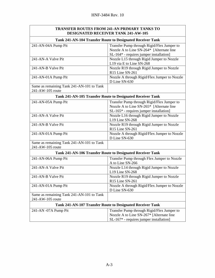
Tank 241-AN-104 Transfer Route to Designated Receiver Tank
241-AN-04A Pump Pit Transfer Pump through Rigid/Flex Jumper to
Nozzle A to Line SN-264* [Alternate line
SL-164* - requires jumper installation]
241-AN-A Valve Pit Nozzle L15 through Rigid Jumper to Nozzle
L19 via E to Line SN-268
241-AN-B Valve Pit Nozzle R19 through Rigid Jumper to Nozzle
R15 Line SN-261
241-AN-01A Pump Pit Nozzle A through Rigid/Flex Jumper to Nozzle
D Line SN-630
Same as remaining Tank 241-AN-101 to Tank
241-AW-105 route
Tank 241-AN-105 Transfer Route to Designated Receiver Tank
241-AN-05A Pump Pit Transfer Pump through Rigid/Flex Jumper to
Nozzle A to Line SN-265* [Alternate line
SL-165* - requires jumper installation]
241-AN-A Valve Pit Nozzle L16 through Rigid Jumper to Nozzle
L19 Line SN-268
241-AN-B Valve Pit Nozzle R19 through Rigid Jumper to Nozzle
R15 Line SN-261
241-AN-01A Pump Pit Nozzle A through Rigid/Flex Jumper to Nozzle
D Line SN-630
Same as remaining Tank 241-AN-101 to Tank
241-AW-105 route
Tank 241-AN-106 Transfer Route to Designated Receiver Tank
241-AN-06A Pump Pit Transfer Pump through Flex Jumper to Nozzle
A to Line SN-266
241-AN-A Valve Pit Nozzle L14 through Rigid Jumper to Nozzle
L19 Line SN-268
241-AN-B Valve Pit Nozzle R19 through Rigid Jumper to Nozzle
R15 Line SN-261
241-AN-01A Pump Pit Nozzle A through Rigid/Flex Jumper to Nozzle
D Line SN-630
Same as remaining Tank 241-AN-101 to Tank
241-AW-105 route
Tank 241-AN-107 Transfer Route to Designated Receiver Tank
241-AN -07A Pump Pit Transfer Pump through Rigid/Flex Jumper to
Nozzle A to Line SN-267* [Alternate line
SL-167* - requires jumper installation]
Page 34
HNF-3484 Rev. 10
A-4
TRANSFER ROUTES FROM 241-AN PRIMARY TANKS TO
DESIGNATED RECEIVER TANK 241-AW-105
Tank 241-AN-107 Transfer Route to Designated Receiver Tank
241-AN-A Valve Pit Nozzle L1 through Rigid Jumper to Nozzle
L19 Line SN-268. A jumper installation is
required. 241-AN-B Valve Pit Nozzle R19 through Rigid Jumper to Nozzle
R15 Line SN-261
241-AN-01A Pump Pit Nozzle A through Rigid/Flex Jumper to Nozzle
D Line SN-630
Same as remaining Tank 241-AN-101 to Tank
241-AW-105 route
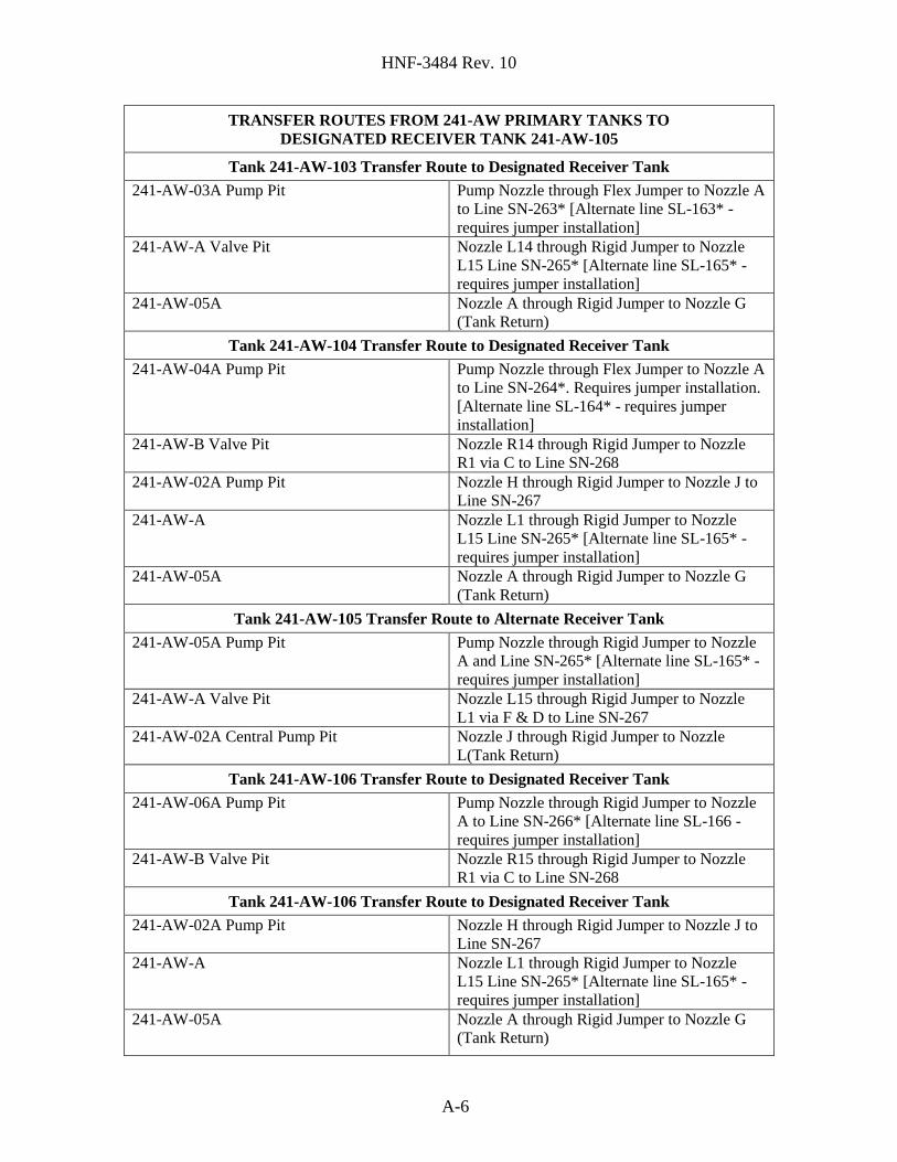
TRANSFER ROUTES FROM 241-AP PRIMARY TANKS TO
DESIGNATED RECEIVER TANK 241-AW-105
Tank 241-AP-101 Transfer Route to Designated Receiver Tank
241-AP-01A Pump Pit Transfer Pump through Rigid Jumper to Nozzle
A to Line SN-611
241-AP Valve Pit Nozzle 18 through Rigid Jumper to Nozzle 14
to Line SN-609
241-AW-02A Nozzle V through Rigid Jumper to Nozzle J
Line SN-267
241-AW-A Nozzle L1 through Rigid Jumper to Nozzle
L15 Line SN-265* [Alternate line SL-165* -
requires jumper installation]
241-AW-05A Nozzle A through Rigid Jumper to Nozzle G
(Tank Return)
Tank 241-AP-102 Transfer Route to Designated Receiver Tank
241-AP-02D Transfer pump through flex/rigid jumper to
Nozzle A to Line SN-622. Jumper installation
required.
241-AP-02A Pump Pit Nozzle Q through Rigid Jumper to Nozzle A
to Line SN-612
Same as remaining Tank 241-AP-101 to Tank
241-AW-105 route
Tank 241-AP-103 Transfer Route to Designated Receiver Tank
241-AP-03A Pump Pit Transfer Pump through Rigid Jumper to Nozzle
A to Line SN-613
Same as remaining Tank 241-AP-101 to Tank
241-AW-105 route
Tank 241-AP-104 Transfer Route to Designated Receiver Tank
241-AP-04A Pump Pit Transfer Pump through Rigid Jumper to Nozzle
A to Line SN-614
Same as remaining Tank 241-AP-101 to Tank
241-AW-105 route
Page 35
HNF-3484 Rev. 10
A-5
TRANSFER ROUTES FROM 241-AP PRIMARY TANKS TO
DESIGNATED RECEIVER TANK 241-AW-105
Tank 241-AP-105 Transfer Route to Designated Receiver Tank
241-AP-05A Pump Pit Transfer Pump through Rigid Jumper to Nozzle
A to Line SN-615
Same as remaining Tank 241-AP-101 to Tank
241-AW-105 route
Tank 241-AP-106 Transfer Route to Designated Receiver Tank
241-AP-06A Pump Pit Transfer Pump through Rigid Jumper to Nozzle
A to Line SN-616
Same as remaining Tank 241-AP-101 to Tank
241-AW-105 route
Tank 241-AP-107 Transfer Route to Designated Receiver Tank
241-AP-07A Pump Pit Transfer Pump through Rigid Jumper to Nozzle
A to Line SN-617
Same as remaining Tank 241-AP-101 to Tank
241-AW-105 route
Tank 241-AP-108 Transfer Route to Designated Receiver Tank
241-AP-08A Pump Pit Transfer Pump through Rigid Jumper to Nozzle
A to Line SN-618
Same as remaining Tank 241-AP-101 to Tank
241-AW-105 route
TRANSFER ROUTES FROM 241-AW PRIMARY TANKS TO
DESIGNATED RECEIVER TANK 241-AW-105
Tank 241-AW-101 Transfer Route to Designated Receiver Tank
241-AW-01A Pump Pit Pump Nozzle through Flex/Rigid Jumper to
Nozzle A to Line SN-261
241-AW-A Valve Pit Nozzle L16 through Rigid Jumper to Nozzle
L15 Line SN-265* [Alternate line SL-165* -
requires jumper installation]
241-AW-05A Nozzle A through Rigid Jumper to Nozzle G
(Tank Return)
Tank 241-AW-102 Transfer Route to Designated Receiver Tank
241-AW-02E Pump Pit Pump Nozzle through Rigid Jumper to Nozzle
D to Line SN-272
241-AW-02A Pump pit Nozzle K through Flex Jumper to Nozzle Q to
Line SN-268 (requires jumper installation)
241-AW-A Nozzle L1 through Rigid Jumper to Nozzle
L15 Line SN-265* [Alternate line SL-165* -
requires jumper installation]
241-AW-05A Nozzle A through Rigid Jumper to Nozzle G
(Tank Return)
Page 36
HNF-3484 Rev. 10
A-6
TRANSFER ROUTES FROM 241-AW PRIMARY TANKS TO
DESIGNATED RECEIVER TANK 241-AW-105
Tank 241-AW-103 Transfer Route to Designated Receiver Tank
241-AW-03A Pump Pit Pump Nozzle through Flex Jumper to Nozzle A
to Line SN-263* [Alternate line SL-163* -
requires jumper installation]
241-AW-A Valve Pit Nozzle L14 through Rigid Jumper to Nozzle
L15 Line SN-265* [Alternate line SL-165* -
requires jumper installation]
241-AW-05A Nozzle A through Rigid Jumper to Nozzle G
(Tank Return)
Tank 241-AW-104 Transfer Route to Designated Receiver Tank
241-AW-04A Pump Pit Pump Nozzle through Flex Jumper to Nozzle A
to Line SN-264*. Requires jumper installation.
[Alternate line SL-164* - requires jumper
installation]
241-AW-B Valve Pit Nozzle R14 through Rigid Jumper to Nozzle
R1 via C to Line SN-268
241-AW-02A Pump Pit Nozzle H through Rigid Jumper to Nozzle J to
Line SN-267
241-AW-A Nozzle L1 through Rigid Jumper to Nozzle
L15 Line SN-265* [Alternate line SL-165* -
requires jumper installation]
241-AW-05A Nozzle A through Rigid Jumper to Nozzle G
(Tank Return)
Tank 241-AW-105 Transfer Route to Alternate Receiver Tank
241-AW-05A Pump Pit Pump Nozzle through Rigid Jumper to Nozzle
A and Line SN-265* [Alternate line SL-165* -
requires jumper installation]
241-AW-A Valve Pit Nozzle L15 through Rigid Jumper to Nozzle
L1 via F & D to Line SN-267
241-AW-02A Central Pump Pit Nozzle J through Rigid Jumper to Nozzle
L(Tank Return)
Tank 241-AW-106 Transfer Route to Designated Receiver Tank
241-AW-06A Pump Pit Pump Nozzle through Rigid Jumper to Nozzle
A to Line SN-266* [Alternate line SL-166 -
requires jumper installation]
241-AW-B Valve Pit Nozzle R15 through Rigid Jumper to Nozzle
R1 via C to Line SN-268
Tank 241-AW-106 Transfer Route to Designated Receiver Tank
241-AW-02A Pump Pit Nozzle H through Rigid Jumper to Nozzle J to
Line SN-267
241-AW-A Nozzle L1 through Rigid Jumper to Nozzle
L15 Line SN-265* [Alternate line SL-165* -
requires jumper installation]
241-AW-05A Nozzle A through Rigid Jumper to Nozzle G
(Tank Return)
Page 37
HNF-3484 Rev. 10
A-7
TRANSFER ROUTES FROM 241-AY PRIMARY TANKS TO
DESIGNATED RECEIVER TANK 241-AW-105
Tank-241-AY-101 Transfer Route to Designated Receiver Tank
241-AY-01A Pump Pit Pump Nozzle through Flex Jumper to Nozzle
U13 to Line SN-635
241-AY-02A Pump Pit Nozzle U12 through Flex/Rigid Jumper to
Nozzle U5 to Line SN-633
241-AZ Valve Pit Nozzle F through Rigid Jumper to Nozzle E
Line SN-634
241-AP-02D Valve Pit Nozzle S through Rigid Jumper to Nozzle A to
Line SN-622
241-AP-02A Pump Pit Nozzle Q through Rigid Jumper to Nozzle A
Line SN-612
241-AP Valve Pit Nozzle 19 through Rigid Jumpers to Nozzle 14
Line SN-609
241-AW-02A Nozzle V through Rigid Jumper to Nozzle J
Line SN-267
241-AW-A Nozzle L1 through Rigid Jumper to Nozzle
L15 Line SN-265* [Alternate line SL-165* -
requires jumper installation]
241-AW-05A Nozzle A through Rigid Jumper to Nozzle G
(Tank Return)
Tank 241-AY-102 Transfer Route to Designated Receiver Tank
241-AY-02A Pump Pit Pump Nozzle through Flex Jumper to Nozzle
U5 to Line SN-633
Same as remaining Tank 241-AY-101 to Tank
241-AW-105 route
TRANSFER ROUTES FROM 241-AZ PRIMARY TANKS TO
DESIGNATED RECEIVER TANK 241-AW-105
Tank 241-AZ-101 Transfer Route to Designated Receiver Tank
241-AZ-01A Pump Pit Pump Nozzle through Flex Jumper to Nozzle
U12 to Line SN-632
241-AZ Valve Pit Nozzle H through Rigid Jumper to Nozzle E
Line SN-634
241-AP-02D Valve Pit Nozzle S through Rigid Jumper to Nozzle A to
Line SN-622
241-AP-02A Pump Pit Nozzle Q through Rigid Jumper to Nozzle A
Line SN-612
241-AP Valve Pit Nozzle 19 through Rigid Jumpers to Nozzle 14
Line SN-609
241-AW-02A Nozzle V through Rigid Jumper to Nozzle J
Line SN-267
241-AW-A Nozzle L1 through Rigid Jumper to Nozzle
L15 Line SN-265* [Alternate line SL-165* -
requires jumper installation]
Page 38
HNF-3484 Rev. 10
A-8
241-AW-05A Nozzle A through Rigid Jumper to Nozzle G
(Tank Return)
Tank 241-AZ-102 Transfer Route to Designated Receiver Tank
241-AZ-02A Pump Pit Pump Nozzle through Flex Jumper to Nozzle
U13 to Line SN-631
241-AZ-01A Pump Pit Nozzle 11 through Flex Jumper to Nozzle U12
to Line SN-632
241-AZ Valve Pit Nozzle H through Rigid Jumper to Nozzle E
Line SN-634
Same as remaining Tank 241-AZ-101 to Tank
241-AW-105 route
TRANSFER ROUTES FROM 241-SY PRIMARY TANKS
TO DESIGNATED RECEIVER TANK 241-AW-105
Tank 241-SY-101 Transfer Route to Designated Receiver Tank
241-SY-101 Prefabricated Pump Pit Pump Nozzle through Rigid Jumper to Over
Ground Transfer Line
241-SY-A Valve Pit Rigid/Flex Jumper Nozzle I to Nozzle L12 via
L & H to line SNL-3150
241-AN-01A Nozzle H through Flex Jumper to Nozzle D
Line SN-630
241-AZ Valve Pit Nozzle A through Rigid Jumper to Nozzle E to
Line SN-634
241-AP-02D Valve Pit Nozzle S through Rigid Jumper to Nozzle A to
Line SN-622
241-AP-02A Pump Pit Nozzle Q through Rigid Jumper to Nozzle A
Line SN-612
241-AP Valve Pit Nozzle 19 through Rigid Jumpers to Nozzle 14
Line SN-609
241-AW-02A Nozzle V through Rigid Jumper to Nozzle J
Line SN-267
241-AW-A Nozzle L1 through Rigid Jumper to Nozzle L15
Line SN-265* [Alternate line SL-165* -
requires jumper installation]
241-AW-05A Nozzle A through Rigid Jumper to Nozzle G
(Tank Return)
Tank 241-SY-102 Transfer Route to Designated Receiver Tank
241-SY-102 Pump Pit Pump Nozzle through Rigid Jumper to Nozzle J
Line SN-285 (Variance) [Alternate variance
Lines SL-177 and SN-277 - requires jumper
installation]
241-SY-A Valve Pit Nozzle L11 through Flex/Rigid Jumper to
Nozzle L12 Line SNL-3150
Same as remaining Tank 241-SY-101 to Tank
241-AW-105 route
Page 39
HNF-3484 Rev. 10
A-9
TRANSFER ROUTES FROM 241-SY PRIMARY TANKS
TO DESIGNATED RECEIVER TANK 241-AW-105
Tank 241-SY-103 Transfer Route to Designated Receiver Tank
241-SY-03A Pump Pit Pump Nozzle through Flex Jumper to Nozzle A
to Line SN-279 (Variance) [Alternate variance
Line SL-179 - requires jumper installation]
241-SY-B Valve Pit Nozzle R14 through Flex Jumper to Nozzle
R19 to Line SN-280 (Variance) [Alternate
variance Line SN-286 from SY-B to SY-02A -
requires jumper installation]
241-SY-A Valve Pit Nozzle L19 through Flex Jumper to Nozzle L16
via H to Line SN-277 (Variance) [Alternate
variance Line SL-177 - requires jumper
installation]
241-SY-02A Pump Pit Nozzle A through Rigid Jumper to Nozzle G
(Tank Return) into Tank SY-102
Waste would then be pumped from 241-SY-
102 to 241-AW-105 using its specified route.
* Denotes Deferred Use Component
[] - Denotes alternate line for deferred use/variance lines not yet tested.
Page 40
HNF-3484 Rev. 10
B-1
APPENDIX B
LIST OF IMPLEMENTING PROCEDURES AND RELEVANT DRAWINGS
Page 41
HNF-3484 Rev. 10
B-2
APPENDIX B
DST ANNULUS EMERGENCY PUMPING PROCEDURES
TANK
FARM
PROCEDURE
NUMBER PROCEDURE TITLE
AN TO-001-281 Emergency Annulus Pumping Procedure for AN Farm
AP TO-001-282 Emergency Annulus Pumping Procedure for AP Farm
AW TO-001-283 Emergency Annulus Pumping Procedure for AW Farm
AY TO-001-288 Emergency Annulus Pumping Procedure for AY Farm
AZ TO-001-289 Emergency Annulus Pumping Procedure for AZ Farm
SY TO-001-284 Emergency Annulus Pumping Procedure for SY Farm
Page 42
HNF-3484 Rev. 10
B-3
APPENDIX B
PIPING AND INSTRUMENT DIAGRAMS
TANK FARM DWG. NO. TITLE
AN
H-14-020501 WASTE STORAGE TANK ANNULUS INSTM SYS WSTA
O&M SYS P&ID
H-14-020601 WASTE STORAGE TANK INSTM SYSTEM WST O&M
SYSTEM P&ID
H-14-020801 WASTE TRANSFER SYSTEM-WST-O&M SYSTEM
P&ID
AP
H-14-020503 WASTE STORAGE TANK ANNULUS INSTM SYS WSTA
O&M SYS P&ID
H-14-020603 WASTE STORAGE TANK INSTR SYSTEM WST O&M
SYSTEM P&ID
H-14-020803 WASTE TRANSFER SYSTEM (WT) O&M SYSTEM
P&ID
AW
H-14-020502 WASTE STORAGE TANK ANNULUS INSTM SYS WSTA
O&M SYS P&ID
H-14-020602 WASTE STORAGE TANK INSTM SYSTEM WST O&M
SYSTEM P&ID
H-14-020803 WASTE TRANSFER SYSTEM-WT-O&M SYSTEM P&ID
AY
H-14-020506 WASTE STORAGE TANK ANNULUS INSTM SYS WSTA
O&M SYS P&ID
H-14-020606 WASTE STORAGE TANK INSTM SYSTEM WST O&M
SYSTEM P&ID
H-14-020806 WASTE TRANSFER SYSTEM (WT) O&M SYSTEM
P&ID
H-14-020507 WASTE STORAGE TANK ANNULUS INSTM SYS WSTA
O&M SYS P&ID
AZ
H-14-020607 WASTE STORAGE TANK INSTM SYSTEM WST O&M
SYSTEM P&ID
H-14-020807 WASTE TRANSFER SYSTEM (WT) O&M SYSTEM
P&ID
H-14-020531 WASTE STORAGE TANK ANNULUS SYSTEM (WSTA)
O&M SYSTEM P&ID
SY
H-14-020631 WASTE STORAGE TANK SYSTEM (WST) O&M
SYSTEM P&ID
H-14-020831 WASTE TRANSFER SYSTEM (WT) O&M SYSTEM
P&ID
Page 43
HNF-3484 Rev. 10
B-4
APPENDIX B
ANNULUS PUMPING EQUIPMENT DRAWINGS
DRAWING NO. TITLE
DRAWING LIST
H-14-104118 DRAWING LIST AND AREA MAP
PIPING & VESSEL
H-14-103869 SH 1 TEST SKID SUBMERSIBLE PUMP ARRANGEMENT
H-14-103869 SH 2 TEST SKID SUBMERSIBLE PUMP VIEWS AND DETAILS
H-14-103870 AIR PUMP IN TANK TEST ARRANGEMENT
H-14-103871 SH 1 MOCK ANNULUS RISER AND LOWER PUMP ARRANGEMENT
H-14-103871 SH 2 MOCK ANNULUS RISER AND LOWER PUMP DETAILS
H-14-103873 JUMPER ASSEMBLY ANNULUS PUMP PITS PRELIMINARY FABRICATION
H-14-104122 JUMPER ARRANGEMENT ANNULUS PUMP PIT 241-AN-01B THRU –07B
H-14-104123 SH 1 JUMPER ARRANGEMENT ANNULUS PUMP PIT 241-AP-01B, 03B, 06B, 08B
H-14-104123 SH 2 JUMPER ARRANGEMENT ANNULUS PUMP PIT 241-AP-02B, 04B, 05B, 07B
H-14-104124 JUMPER ARRANGEMENT ANNULUS PUMP PIT 241-AW-01B THRU –06B
H-14-104125 JUMPER ARRANGEMENT ANNULUS PUMP PIT 241-AY-01F & -02F
H-14-104126 JUMPER ARRANGEMENT ANNULUS PUMP PIT 241-AZ-01F & -02F
H-14-104127 JUMPER ARRANGEMENT ANNULUS PUMP PIT 241-SY-01B, -02B & -03B
H-14-104128 SH 1&2 JUMPER ASSEMBLY ANNULUS PUMP PIT 241-AN-01B THRU –07B
H-14-104129 SH 1&2 JUMPER ASSEMBLY ANNULUS PUMP PIT 241-AP-01B THRU –08B
H-14-104130 SH 1&2 JUMPER ASSEMBLY ANNULUS PUMP PIT 241-AW-01B THRU –06B
H-14-104131 SH 1&2 JUMPER ASSEMBLY ANNULUS PUMP PIT 241-AY-01F & -02F
H-14-104132 SH 1&2 JUMPER ASSEMBLY ANNULUS PUMP PIT 241-AZ-01F & -02F
H-14-104133 SH 1&2 JUMPER ASSEMBLY ANNULUS PUMP PIT 241-SY-01B, -02B & -03B
H-14-104134 SH 1&2 PUMP ASSEMBLY ANNULUS PUMP PIT 241-AN-01B THRU –07B
ANNULUS PUMPING EQUIPMENT DRAWINGS
DRAWING NO. TITLE
H-14-104135 SH 1&2 PUMP ASSEMBLY ANNULUS PUMP PIT 241-AP-01B THRU –08B
H-14-104136 SH 1&2 PUMP ASSEMBLY ANNULUS PUMP PIT 241-AW-01B THRU –06B
H-14-104137 SH 1&2 PUMP ASSEMBLY ANNULUS PUMP PIT 241-AY-01F & -02F
H-14-104138 SH 1&2 PUMP ASSEMBLY ANNULUS PUMP PIT 241-AZ-01F & -02F
H-14-104139 SH 1&2 PUMP ASSEMBLY ANNULUS PUMP PIT 241-SY-01B, -02B & -03B
Page 44
HNF-3484 Rev. 10
B-5
APPENDIX B
ANNULUS PUMPING EQUIPMENT DRAWINGS
DRAWING NO. TITLE
H-14-104140 SUBMERSIBLE PUMP ASSEMBLY MODIFICATIONS
DRAWING NO. TITLE
ELECTRICAL
H-14-104119 DST ANNULUS PUMPING UTILITY WIRING DIAGRAM
H-14-104120 DST ANNULUS PUMP SYSTEM – FUSED DISCONNECT SKID ASSY
H-14-104141 SH 1 DST ANNULUS PUMP SYSTEM – FIELD RACK ARRANGEMENT
H-14-104141 SH 2 DST ANNULUS PUMP SYSTEM – FIELD RACK ARRANGEMENT
H-14-104141 SH 3 DST ANNULUS PUMP SYSTEM – FIELD RACK SCHEMATIC
H-14-104141 SH 4 DST ANNULUS PUMP SYSTEM – FIELD RACK ASSEMBLY
H-14-104142 DST ANNULUS PUMP UTILITY ARRANGEMENT 241-AN TANK FARM
H-14-104143 DST ANNULUS PUMP UTILITY ARRANGEMENT 241-AP TANK FARM
H-14-104144 DST ANNULUS PUMP UTILITY ARRANGEMENT 241-AW TANK FARM
H-14-104145 DST ANNULUS PUMP UTILITY ARRANGEMENT 241-AY TANK FARM
H-14-104146 DST ANNULUS PUMP UTILITY ARRANGEMENT 241-AZ TANK FARM
H-14-104147 DST ANNULUS PUMP UTILITY ARRANGEMENT 241-SY TANK FARM
Page 45
HNF-3484 Rev. 10
C-1
APPENDIX C
IDENTIFICATION AND LOCATION OF DST PUMPS AND JUMPERS
THAT WOULD BE USED FOR EMERGENCY PUMPING
Page 46
HNF-3484 Rev. 9
C-2
Facility
Location
Pump
PitPump Use
Pump #
Currently Pump Length
Fabrication
Drawing
Pump Pit
Clearance **
Pump Flange to
Bottom of Tank
Jumpers install
for transfer
Jumper
DrawingComments
TK - 101 01A Transfer
AN01A-WT-P-
022
36'-0 11/16" with
adjustable intake
CVI 50301
Sup 2 4'-5 3/64" 49'-9" Yes H-14-104547
01B Annulus Open 46' 2 1/2" H-14-104134 8'-2 7/32" 46'-5 1/4"
No, w/isolation
blanks H-14-104128
TK-102 02A Transfer 65P-TX4 49'-0 1/2" H-2-46205 4'-5 3/32" 49'-9" No H-2-72026
02B Annulus Open 46' 2 1/2" H-14-104134 8'-2 7/32" 46'-5 1/4"
No, w/isolation
blanks H-14-104128
TK-103 03A Transfer 202P-TX1 49'-0 3/8" H-2-91943 4'-4 23/32" 49'-9 3/8" No H-2-94863
03B Annulus Open 46' 2 1/2" H-14-104134 8'-2 7/32" 46'-5 1/4"
No, w/isolation
blanks H-14-104128
TK-104 04A Transfer 64P-TX4 49'-0 1/2" H-2-91943 4'-4 23/32" 49'-9 31/64" No H-2-94863
04B Annulus Open 46' 2 1/2" H-14-104134 8'-2 7/32" 46'-5 1/4"
No, w/isolation
blanks H-2-104128
TK-105 05A Transfer 84P-TX4/SW 49'-0 3/8" H-2-91943 4'-4 23/32" 49'-9 31/64" No H-2-94863
05B Annulus Open 46' 2 1/2" H-14-104134 8'-2 7/32" 46'-5 1/4"
No, w/isolation
blanks H-14-104128
TK-106 06A Transfer
AN06A-WT-P-
022 36' 9-7/8"
CVI 50306
Sup 1 4'-4 23/32" 49'-9 1/8" Yes H-14-107489
2P-TX1-XCF is installed but is
not operable
06B Annulus Open 46' 2 1/2" H-14-104134 8'-2 7/32" 46'-5 1/4"
No, w/isolation
blanks H-14-104128
TK-107 07A Transfer Open 49'-0 3/8" H-2-91943 4'-4 23/32" 49'-9 1/8" No H-2-72026
07B Annulus Open 46' 2 1/2" H-14-104134 8'-2 7/32" 46'-8 3/8"
No, w/isolation
blanks H-14-104128
** Pump Pit Clearance is taken from face of flange to bottom of cover block
241-AN Tank Farm
IDENTIFICATION AND LOCATION OF DST PUMPS AND JUMPERS THAT WOULD BE USED FOR EMERGENCY PUMPING
Page 47
HNF-3484 Rev. 9
C-3
Facility
Location
Pump
PitPump Use
Pump #
Currently
Installed
Pump
Length
Fabrication
Drawing
Pump Pit
Clearance **
Pump Flange to
Bottom of Tank
Jumpers install
for transfer
Jumper
DrawingComments
TK-101 01A Transfer T60V4149'2"
CVI 50295 4'-9 13/16" 49'-5 11/16" Yes H-14-010802
01B Annulus Open 46' 2 1/2" H-14-104135 8'-9 3/4" 46'-4 11/16"
NO, w/isolation
blanks H-14-104129
TK-102 02B Annulus Open 46' 2 1/2" H-14-104135 8'-9 3/4" 46'-4 11/16"
NO, w/isolation
blanks H-14-104129
02D Transfer 1-TX-XCF
44'-7"
w/screen H-2-91943 9'-3 19/64" 44'-8 13/64" No Flex required
TK-103 03A Transfer 2P-AP-3 49'-0 3/8" H-2-91943 4'-9 25/64" 49'-5 23/32" Yes H-2-90725
Spare run -in completed
11/29/89. Has Graphite
bearings. 30 HP. 160 GPM at
250' TDH
03B Annulus Open 46' 2 1/2" H-14-104135 8'-9 3/4" 46'-4 11/16"
NO, w/isolation
blanks H-14-104129
TK-104 04A Transfer 4P-AP-3 49'-0 3/8" H-2-91943 4'-9 27/32" 49'-5 21/32" Yes H-2-90725
04B Annulus Open 46' 2 1/2" H-14-104135 8'-9 3/4" 46'-4 11/16"
NO, w/isolation
blanks H-14-104129
TK-105 05A Transfer 1P-AP-3 49'-0 3/8" H-2-91943 4'-9 13/16" 49'-5 11/16" Yes H-2-90725
05B Annulus Open 46' 2 1/2" H-14-104135 8'-9 3/4" 46'-4 11/16"
NO, w/isolation
blanks H-14-104129
TK-10606A Transfer 2P-AP-4
33'-0" Flex
Float H-2-91943 4'-9 53/64" 49'-5 43/64" Yes H-2-90725
06B Annulus Open 46' 2 1/2" H-14-104135 8'-9 3/4" 46'-4 11/16"
NO, w/isolation
blanks H-14-104129
TK-10707A Transfer Open 49'-0 3/8" H-2-91943 4'-9 49/64" 49'-5 47/64" Yes H-2-90725
07B Annulus Open 46' 2 3/8" H-14-104135 8'-9 3/4" 46'-4 11/16"
NO, w/isolation
blanks H-14-104129
TK-10808A Transfer
1P-TX4-XCR-
1 49'-0 3/8" H-2-91943 4'-9 45/64" 49'-5 45/64" Yes H-2-90725
08B Annulus Open 46' 2 1/2" H-14-104135 8'-9 3/4" 46'-4 11/16"
NO, w/isolation
blanks H-14-104129
241-AP Tank Farm
** Pump Pit Clearance is taken from face of flange to bottom of cover block
IDENTIFICATION AND LOCATION OF DST PUMPS AND JUMPERS THAT WOULD BE USED FOR EMERGENCY PUMPING
Page 48
HNF-3484 Rev. 9
C-4
Facility
Location
Pump
Pit
Pump
Use
Pump #
Currently
Installed
Pump
Length
Fabrication
Drawing
Pump Pit
Clearance **
Pump Flange to
Bottom of Tank
Jumpers install for
transferJumper Drawing Comments
TK - A Transfer
85P TX4 (Oil
Lubed)49'-0 3/8"
H-2-91943 4'-5 21/32" 49'-5 15/32" No H-2-70445
B Annulus Open 46'-2 1/2" H-14-104136 8'-3 25/64" 45'-4 15/32" No, w/isolation blanks H-14-104130
TK-1 E Transfer 78P-TX4 45'-3 3/8" H-2-91943 8'-3 5/32" 45'-7 31/32" No None
B Annulus Open 46' 2 1/2" H-14-104136 8'-3 27/64" 46'-4 13/64" No, w/isolation blanks H-14-104130
TK-1 A Transfer 1P-TX1 XCR-1
33' 0"
Flex Float H-2 91943 4'-5 21/32" 49'-5 15/32" No H-2-70445
03B Annulus Open 46' 2 1/2" H-14-104136 5'-3 3/16" 46'-4 7/16" No, w/isolation blanks H-14-104130
TK-1 0 A Transfer 3P-TX1-XCR-1 41'-0" H-2-91943 4'-5 55/64" 49'-5 45/64" No H-2-70445
B Annulus Open 46' 2 1/2" H-14-104136 8'-3 3/16" 45'-4 7/16" No, w/isolation blanks H-14-104130
TK-1 A Transfer 1P-TX1
33'-0"
Flex Float H-2-91943 4'-5 11/16" 49'-5 7/16" Yes H-2-70445
B Annulus Open 46' 2 1/2" H-14-104136 8'-3 13/64" 46'-4 27/64" No, w/isolation blanks H-14-104130
TK-106 06A Transfer 1P-TX1-XCR-1 49' 0 3/8" H-2-91943 4'-5 53/64" 49'-5 19/64" Yes H-2-70445
06B Annulus Open 46' 2 1/2" H-14-104136 8'-3 3/16" 46'-4 7/16" No, w/isolation blanks H-14-104130
IDENTIFICATION AND LOCATION OF DST PUMPS AND JUMPERS THAT WOULD BE USED FOR EMERGENCY PUMPING
** Pump Pit Clearance is taken from face of flange to bottom of cover block
241-AW Tank Farm
TK 101 01A Transfer 1300682N
Max 36'-2"
Adjustable
Length
H-14-107390,
CVI 50330 Sup
3 4' 10 5/8" 49' 6 1/2" Yes H 14 107642
To be installed
FY 2009
01B Transfer F64GT Unknown 5'-10 5/8" 49'-0 1/8" Yes H-2-64421
No info
availiable on
this pump
01D Transfer 122P-10 47'-3 3/8" H-2-65054 5'-10 5/8" 48'-0 1/8" Tes H-2-64421
01F Annulus Open 46'-1 9/16" H-14-104137 8'-3 1/2" 46'-4 1/2" No H-14-104131
TK-102 02A Transfer AY02A-WT-P-022 43'- 4 /12" CVI 22541 4'-10 5/8" 49'-6 1/2" Yes H-14-106842
02D Transfer 57P-TX-4/9PTX6 47'-3 3/8" H-2-93179 5'-10 5/8" 48'-0 1/8" Yes H-2-64421
02E Transfer PO621/PO622 Adjustable H-2-818494 5'-10 5/8" 48'-0 1/8" Yes H-2-818503 W-320 Project
02F Annulus Open 46'-1 9/16" H-14-104137 8'-3 1/2" 46'-4 1/2" No H-14-104131
** Pump Pit Clearance is taken from face of flange to bottom of cover block
Page 49
HNF-3484 Rev. 9
C-5
Facility
Location
Pump
PitPump Use
Pump # Currently
Installed
Pump
Length
Fabrication
Drawing
Pump Pit
Clearance **
Pump Flange to
Bottom of Tank
Jumpers Install for
Transfer
Jumper
DrawingComments
TK - 101 01C Transfer 74-TX4/1P-TX5 47'-3 3/8" H-2-93179 7'-2 49/64" 47'-11 63/64 Yes H-2-68427
01F Annulus Open 46'-1 9/16" H-14-104138 8'-3 31/64" 46'-4 21/64"
No, w/isolation
blanks
H-14-
104132
TK-102 02A Transfer 1P-TX1-XCR-2 45'-3 5/8"
H-2-91943-9,
CVI 22044 6'-6 5/8" 49'-7 13/64" Yes
H-2-92058-
050
02B Transfer Open 46'-1 9/16" H-2-93179 7'-2 49/64" 47'-11 63/64 No H-2-68427
02F Annulus Open 46'-1 9/16" H-14-104138 8'-3 31/64" 46'-4 21/64"
No, w/isolation
blanks
H-14-
104132
** Pump Pit Clearance is taken from face of flange to bottom of cover block
IDENTIFICATION AND LOCATION OF DST PUMPS AND JUMPERS THAT WOULD BE USED FOR EMERGENCY PUMPING
241-AZ Tank Farm
Page 50
HNF-3484 Rev. 9
C-6
Facility
LocationPump Pit Pump Use
Pump #
Currently
Installed
Pump
Length
Fabrication
Drawing
Spare
Pump #
Pump Pit
Clearance **
Pump Flange
to Bottom of
Tank
Jumpers Install
for Transfer
Jumper
DrawingComments
TK - 101
01A Riser
3A Transfer Open TBD
H-2-75352 &
H-2-46206
4'-5 11/16" 47'-6 9/16" No H-2-46215
One of the spares is
located in 400 area
(FFTF), and the other is
in 2101M01A Riser
2A Mixer N/A 48'-1 1/8" H-2-821329 2 each 3'-8 1/4" 50'-2 11/16" N/A N/A
Riser 007 Transfer 2A-513-A1 47'-3" CVI 50071 55'-9" Yes H-14-103616
01B Annulus Open 46' 2 1/2" H-14-104139 No 8'-3 3/16" 46'-4 13/16" No H-14-104133
TK-102 02A X-Site SY-02A-3 33' Flex Flo
H-2-75352 &
H-2-46205 1P-Sy1-102 4'-5 11/16" 47'-6 9/16" Yes H-2-37782
02B Annulus Open 46' 2 1/2"H-14-104139
No 8'-3 3/16" 46'-4 13/16" No H-14-104133
35 feet of the old pump
broke off in tank
02E Transfer 49-PTX-4 36'-8" ? No 8'-4 15/16 45"-8 3/16" Yes H-2-37812
TK-103 03A Transfer 116P-10 47'-0"
H-2-75352 &
H-2-46206 No 4'-5 11/16" 47'-6 9/16" No H-2-46215
03B Annulus Open 46' 2 1/2" H-14-104139 No 8'-3 3/16" 46'-4 13/16" No H-14-104133
** Pump Pit Clearance is taken from face of flange to bottom of cover block
IDENTIFICATION AND LOCATION OF DST PUMPS AND JUMPERS THAT WOULD BE USED FOR EMERGENCY PUMPING
241-SY Tank Farm
Page 51
HNF-3484 Rev. 9
C-7
Spare Primary Tank Pumps
Pumps Stored at 2101-M on Hanford Site
1) Vertical Turbine Standard Inlet (49’) – 6411-2225-5672, Cat. ID# 561300, 6411-2225-2P-TX1-XCR-1, Floway Pumps Inc.,
AN/AP/AW Compatible, H-2-91943 Assembly 5, Specification for Refurbishment, Modification and Testing for Vertical Turbine
Transfer Pumps, RPP-10745.
2) Vertical Turbine Flexible Inlet (33’) – 6411-2225-5677, Cat. ID# 561304, 6411-2225-1P-TX4-XCR-2, Floway Pumps Inc.,
AN/AP/AW Compatible, H-2-91943 Assembly 7, 17-foot flex & float, Specification for Refurbishment, Modification and Testing
for Vertical Turbine Transfer Pumps, RPP-10745.
3) Vertical Turbine Flexible Inlet (33’) – 6411-2187-5655, Cat. ID# 561285, S/N TC-6703 VIN 22534, Johnston Pump Co., Cross-
site 241-SY-102, H-14-106255, Specification for Refurbishment, Design, Modification and Testing of Vertical Turbine Transfer
Pump for Tank 241-SY-102, RPP-18672.
4) Vertical Turbine (45.3’) – 6411-2225-5676, Cat. ID# 561304, 6411-2225-2P-TX1-XCR-2, Floway Pump Inc., Evaporator Feed
241-AW-02E, H-2-91943-9 Specification for Refurbishment, Modification and Testing of Vertical Turbine Transfer Pump for
Tank 241-AW-102, RPP-20202.
Support Equipment for Pumps (Stored at 2101-M on Hanford Site)
1) Flex and Float Assembly F/A Pump for Vertical Turbine Flexible Inlet (Pump #3 on above list) – Cat. ID 630851, H-2-38654 and
H-2-91943.
Page 52
HNF-3484 Rev. 9
D-1
APPENDIX D
CROSS SECTION OF ANNULUS OF
DOUBLE-SHELL TANK
Page 53
HNF-3484 Rev. 9
D-2
Cross-Section of Annulus of Double-Shell Tank
PROBLEM: Calculate volume of liquid in annulus at various depths.
ASSUMPTIONS: Reference drawings H-2-37772, and H-2-37705 are accurate.
Insulating concrete absorbs no liquid. SY-101 is representative of all DSTs.
Volume can be approximated by dividing annulus space into relatively simple geometric
forms and calculating the volume of those forms.
Forms A & B are squat hollow cylinders where Volume = Pi height (radiuso2
– radiusj2).
a = 1.75 ft from 0 to 8 inches above bottom; a = 1.50 ft above 8 inches above bottom.
Rs2 = b
2 + c
2 or b = square foot (Rs
2 – c
2)
Volume insulating concrete = Pi height (radius 2) = Pi(0.67)(37.25)
2 = 2,908 ft
3 = 21,780 gal.
Volume per inch in annulus above 12 inches above bottom is constant at 380 gal/inch.
d (inches) a (ft) c (ft) b ft) Vol A
(ft3)
Vol B
(ft3)
Vol A &
B (ft3) Vol (gal)
Vol Cum
(gal)
1 1.75 0.92 0.40 34.9 8.2 43 323 323
2 1.75 0.83 0.55 34.9 11.4 46 347 670
3 1.75 0.75 0.66 34.9 13.6 49 364 1,034
4 1.75 0.67 0.75 34.9 15.4 50 377 1,410
5 1.75 0.58 0.81 34.9 16.8 52 387 1,797
6 1.75 0.50 0.87 34.9 17.9 53 396 2,193
7 1.75 0.42 0.91 34.9 18.8 54 402 2,595
8 1.75 0.33 0.94 34.9 19.5 54 408 3,003
9 1.50 0.25 0.97 30.0 20.0 50 375 3,378
10 1.50 0.17 0.99 30.0 20.4 50 378 3,756
11 1.50 0.08 1.00 30.0 20.6 51 379 4,135
12 1.50 0.00 1.00 30.0 20.7 51 380 4,515
13 1.50 0.00 1.00 30.0 20.7 51 380 4,895
Insulating Concrete
Primary Tank Secondary Tank
0.67 ft
r = 37.25 ft = 37.5 ft = 39.0 ft = 40.0 ft
A
a b
c
d
Rs = 1.0 ft
Page 54
HNF-3484 Rev. 9
E-1
APPENDIX E
PROPOSED ANNULUS EMERGENCY PUMPING TRANSFER ROUTES
TO DESIGNATED RECEIVER TANK
Page 55
HNF-3484 Rev. 9
E-2
APPENDIX E
The proposed route for emergency pumping of the annulus will be from the Annulus
Pump Pit through rigid/flex jumpers to an encased, below-grade pipeline to the Central
Pump Pit. The route would be jumpered through the central pump pit to the same route
used for transferring waste from the primary tank to the designated receiver tank as
outlined in Appendix A. The transfer pipelines from the Annulus Pump Pit to the
Central Pump Pit for all DST tanks are pipe-in-pipe or encased pipelines except for
Tanks 241-AY-101, 241-AY-102 and 241-AZ-102. The two tanks in AY farm have
direct-buried, unencased pipelines from the annulus pump pits to the central pump. Tank
241-AZ-102 also has a direct-buried unencased pipeline from the annulus pump pit to the
central pump pit. Where possible, alternate transfer lines have been listed for transfer
routes that have deferred use and variance transfer lines. Alternate lines are denoted with
brackets (i.e., [line]).
TRANSFER ROUTES FROM 241-AN ANNULUS TO DESIGNATED RECEIVER
Tank 241-AW-105
Tank 241-AN-101 Annulus Transfer Route to Designated Receiver Tank
241-AN-01B Annulus Pump Pit Transfer Pumps through Rigid/Flex Jumper
to Nozzle A to Line PW-471
241-AN-01A Central Pump Pit Nozzle E through Rigid/Flex Jumper to
nozzle A
Remaining route is the same as 241-AN-101
primary route listed in Appendix A.
Tank 241-AN-102 Annulus Transfer Route to Designated Receiver Tank
241-AN-02B Annulus Pump Pit Transfer Pumps through Rigid/Flex Jumper
to Nozzle A to Line PW-472
241-AN-02A Central Pump Pit Nozzle E through Rigid/Flex Jumper to
nozzle A
Remaining route is the same as 241-AN-102
primary route listed in Appendix A.
Tank 241-AN-103 Annulus Transfer Route to Designated Receiver Tank
241-AN-03B Annulus Pump Pit Transfer Pumps through Rigid/Flex Jumper
to Nozzle A to Line PW-473
241-AN-03A Central Pump Pit Nozzle E through Rigid/Flex Jumper to
nozzle A
Remaining route is the same as 241-AN-103
primary route listed in Appendix A.
Tank 241-AN-104 Annulus Transfer Route to Designated Receiver Tank
241-AN-04B Annulus Pump Pit Transfer Pumps through Rigid/Flex Jumper
to Nozzle A to Line PW-474
241-AN-04A Central Pump Pit Nozzle E through Rigid/Flex Jumper to
nozzle A
Remaining route is the same as 241-AN-104
primary route listed in Appendix A.
Page 56
HNF-3484 Rev. 9
E-3
TRANSFER ROUTES FROM 241-AN ANNULUS TO DESIGNATED RECEIVER
Tank 241-AW-105
Tank 241-AN-105 Annulus Transfer Route to Designated Receiver Tank
241-AN-05B Annulus Pump Pit Transfer Pumps through Rigid/Flex Jumper
to Nozzle A to Line PW-475
241-AN-05A Central Pump Pit Nozzle E through Rigid/Flex Jumper to
nozzle A
Remaining route is the same as 241-AN-105
primary route listed in Appendix A.
Tank 241-AN-106 Annulus Transfer Route to Designated Receiver Tank
241-AN-06B Annulus Pump Pit Transfer Pumps through Rigid/Flex Jumper
to Nozzle A to Line PW-476
241-AN-06A Central Pump Pit Nozzle E through Rigid/Flex Jumper to
nozzle A
Remaining route is the same as 241-AN-106
primary route listed in Appendix A.
Tank 241-AN-107 Annulus Transfer Route to Designated Receiver Tank
241-AN-07B Annulus Pump Pit Transfer Pumps through Rigid/Flex Jumper
to Nozzle A to Line PW-477
241-AN-07A Central Pump Pit Nozzle E through Rigid/Flex Jumper to
nozzle A
Remaining route is the same as 241-AN-107
primary route listed in Appendix A.
TRANSFER ROUTES FROM 241-AP ANNULUS TO DESIGNATED RECEIVER
TANK 241-AW-105
Tank 241-AP-101 Annulus Transfer Route to Designated Receiver Tank
241-AP-01B Annulus Pump Pit Transfer Pumps through Rigid/Flex Jumper
to Nozzle A to Line PW-811
241-AP-01A Central Pump Pit Nozzle C through Rigid/Flex Jumper to
nozzle A
Remaining route is the same as 241-AP-101
primary route listed in Appendix A.
Tank 241-AP-102 Annulus Transfer Route to Designated Receiver Tank
241-AP-02B Annulus Pump Pit Transfer Pumps through Rigid/Flex Jumper
to Nozzle A to Line PW-812
241-AP-02A Central Pump Pit Nozzle C through Rigid/Flex Jumper to
nozzle A
Remaining route is the same as 241-AP-102
primary route listed in Appendix A.
Page 57
HNF-3484 Rev. 9
E-4
TRANSFER ROUTES FROM 241-AP ANNULUS TO DESIGNATED RECEIVER
TANK 241-AP-108
Tank 241-AP-103 Annulus Transfer Route to Designated Receiver Tank
241-AP-03B Annulus Pump Pit Transfer Pumps through Rigid/Flex Jumper
to Nozzle A to Line PW-813
241-AP-03A Central Pump Pit Nozzle C through Rigid/Flex Jumper to
nozzle A
Remaining route is the same as 241-AP-103
primary route listed in Appendix A.
Tank 241-AP-104 Annulus Transfer Route to Designated Receiver Tank
241-AP-04B Annulus Pump Pit Transfer Pumps through Rigid/Flex Jumper
to Nozzle A to Line PW-814
241-AP-04A Central Pump Pit Nozzle C through Rigid/Flex Jumper to
nozzle A
Remaining route is the same as 241-AP-104
primary route listed in Appendix A.
Tank 241-AP-105 Annulus Transfer Route to Designated Receiver Tank
241-AP-05B Annulus Pump Pit Transfer Pumps through Rigid/Flex Jumper
to Nozzle A to Line PW-815
241-AP-05A Central Pump Pit Nozzle C through Rigid/Flex Jumper to
nozzle A
Remaining route is the same as 241-AP-105
primary route listed in Appendix A.
Tank 241-AP-106 Annulus Transfer Route to Designated Receiver Tank
241-AP-06B Annulus Pump Pit Transfer Pumps through Rigid/Flex Jumper
to Nozzle A to Line PW-816
241-AP-06A Central Pump Pit Nozzle C through Rigid/Flex Jumper to
nozzle A
Remaining route is the same as 241-AP-106
primary route listed in Appendix A.
Tank 241-AP-107 Annulus Transfer Route to Designated Receiver Tank
241-AP-07B Annulus Pump Pit Transfer Pumps through Rigid/Flex Jumper
to Nozzle A to Line PW-817
241-AP-07A Central Pump Pit Nozzle C through Rigid/Flex Jumper to
nozzle A
Remaining route is the same as 241-AP-107
primary route listed in Appendix A.
Tank 241-AP-108 Annulus Transfer Route to Alternate Receiver Tank
241-AP-08B Annulus Pump Pit Transfer Pumps through Rigid/Flex Jumper
to Nozzle A to Line PW-818
241-AP-08A Central Pump Pit Nozzle C through Rigid/Flex Jumper to
nozzle A
Remaining route is the same as 241-AP-108
primary route listed in Appendix A.
Page 58
HNF-3484 Rev. 9
E-5
TRANSFER ROUTES FROM 241-AW ANNULUS TO DESIGNATED
RECEIVER TANK 241-AW-105
Tank 241-AW-101 Annulus Transfer Route to Designated Receiver Tank
241-AW-01B Annulus Pump Pit Transfer Pumps through Rigid/Flex Jumper
to Nozzle A to Line PW-471
241-AW-01A Central Pump Pit Nozzle E through Rigid/Flex Jumper to
nozzle A
Remaining route is the same as 241-AW-101
primary route listed in Appendix A.
Tank 241-AW-102 Annulus Transfer Route to Designated Receiver Tank
241-AW 02B Annulus Pump Pit Transfer Pumps through Rigid/Flex Jumper
to Nozzle A to Line PW-472
241-AW-02A Central Pump Pit Nozzle E through Rigid/Flex Jumper to
nozzle Q to Line SN 609
Remaining route is the same as 241-AW-102
primary route listed in Appendix A.
Tank 241-AW-103 Annulus Transfer Route to Designated Receiver Tank
241-AW-03B Annulus Pump Pit Transfer Pumps through Rigid/Flex Jumper
to Nozzle A to Line PW-473
241-AW-03A Central Pump Pit Nozzle E through Rigid/Flex Jumper to
nozzle A
Remaining route is the same as 241-AW-103
primary route listed in Appendix A.
Tank 241-AW-104 Annulus Transfer Route to Designated Receiver Tank
241-AW-04B Annulus Pump Pit Transfer Pumps through Rigid/Flex Jumper
to Nozzle A to Line PW-474
241-AW-04A Central Pump Pit Nozzle E through Rigid/Flex Jumper to
nozzle A
Remaining route is the same as 241-AW-104
primary route listed in Appendix A.
Tank 241-AW-105 Annulus Transfer Route to Designated Receiver Tank
241-AW 05B Annulus Pump Pit Transfer Pumps through Rigid/Flex Jumper
to Nozzle A to Line PW 475
241-AW-05A Central Pump Pit Nozzle E through Rigid/Flex Jumper to
nozzle A
Remaining route is the same as 241-AW-105
primary route listed in Appendix A.
Tank 241-AW-106 Annulus Transfer Route to Designated Receiver Tank
241-AW-06B Annulus Pump Pit Transfer Pumps through Rigid/Flex Jumper
to Nozzle A to Line PW-476
241-AW-06A Central Pump Pit Nozzle E through Rigid/Flex Jumper to
nozzle A
Remaining route is the same as 241-AW-106
primary route listed in Appendix A.
Page 59
HNF-3484 Rev. 9
E-6
TRANSFER ROUTES from 241-AY ANNULUS TO DESIGNATED RECEIVER
Tank 241-AW-105
Tank 241-AY101 Annulus Transfer Route to Designated Receiver Tank
241-AY-01F Annulus Pump Pit Transfer Pumps through Rigid/Flex Jumper
to Nozzle to Line PW-4531
241-AY-01A Central Pump Pit Nozzle U10 through Rigid/Flex Jumper to
nozzle U13 to Line SN-635
Remaining route is the same as 241-AY-101
primary route listed in Appendix A.
Tank 241-AY-102 Annulus Transfer Route to Designated Receiver Tank
241-AY-02F Annulus Pump Pit Transfer Pumps through Rigid/Flex Jumper
to Nozzle to Line PW-4532
241-AY-02A Central Pump Pit Nozzle U10 through Rigid/Flex Jumper to
Nozzle U5 to Line SN-633
Remaining route is the same as 241-AY-102
primary route listed in Appendix A.
TRANSFER ROUTES from 241-AZ ANNULUS TO DESIGNATED RECEIVER
Tank 241-AW-105
Tank 241-AZ-101 Annulus Transfer Route to Designated Receiver Tank
241-AZ-01F Annulus Pump Pit Transfer Pumps through Rigid/Flex Jumper
to Nozzle to Line PW-4623
241-AZ-01A Central Pump Pit Nozzle U3 through Rigid/Flex Jumper to
Nozzle U12 to Line SN-632
Remaining route is the same as 241-AZ-101
primary route listed in Appendix A.
Tank 241-AZ-102 Annulus Transfer Route to Designated Receiver Tank
241-AZ-02F Annulus Pump Pit Transfer Pumps through Rigid/Flex Jumper
to Nozzle U1 to Line PW-4609
241-AZ-02A Central Pump Pit Nozzle U11 through Rigid/Flex Jumper to
Nozzle U13 to Line SN-631
Remaining route is the same as 241-AZ-102
primary route listed in Appendix A.
Page 60
HNF-3484 Rev. 9
E-7
TRANSFER ROUTES FROM 241-SY ANNULUS TO DESIGNATED RECEIVER
TANK 241-AW-105
Tank 241-SY-101 Annulus Transfer Route to Designated Receiver Tank
241-SY-01B Annulus Pump Pit Transfer Pumps through Rigid/Flex Jumper to
Nozzle to a new over-ground line to PPP
Prefabricated Pump Pit Over-ground transfer line from 241-SY-01B to
existing over-ground to 241-SY-A
241-SY-A Valve Pit Nozzle I through Rigid/Flex jumper to Nozzle
L16 via H to Line 277 (Variance)
241-SY-02A Pump Pit Nozzle A through Rigid Jumper to Nozzle G
into Tank 241-SY-102
Waste would then be pumped from 241-SY-
102 to 241-AW-105 per Appendix A route.
Tank 241-SY-102 Annulus Transfer Route to Designated Receiver Tank
241-SY-02B Annulus Pump Pit Transfer Pumps through Rigid/Flex Jumper to
Nozzle A to Line PW-475
241-SY-02A Central Pump Pit Nozzle E through Rigid/Flex Jumper to nozzle
A to Line SN-277 (Variance) [Alternate
variance line SL-177 - requires jumper
installation]
241-SY-A Valve Pit Nozzle L16 through Rigid/Flex jumper to
nozzle I via Over-ground Line to Pre-fabricated
Pump Pit
Pre-Fabricated Pump Pit Over-ground Line nozzle through rigid jumper
to nozzle in riser-007 into Tank 241-SY-101
Waste would then be pumped from 241-SY-
101 to 241-AW-105 per Appendix A route.
Tank 241-SY-103 Annulus Transfer Route to Designated Receiver Tank
241-SY 03B Annulus Pump Pit Transfer Pumps through Rigid/Flex Jumper to
Nozzle A to Line PW-479
241-SY-03A Central Pump Pit Nozzle E through Rigid/Flex Jumper to nozzle
A to line SN-279 (Variance) [Alternate
variance line SL-179 - requires jumper
installation]
241-SY-B Valve Pit Nozzle R14 through Rigid/Flex jumper to
Nozzle R19 to line SN-280 (Variance)
[Alternate variance Line SN-286 from SY-B to
SY-02A - requires jumper installation]
241-SY-A Valve Pit Nozzle L19 through Rigid/Flex jumper to
Nozzle L16 via H to line SN-277(Variance)
[Alternate variance line SL-177 - requires
jumper installation]
241-SY-02A Central Pump Pit Nozzle A through Rigid jumper to Nozzle G
into Tank 241-SY-102
Waste would then be pumped from 241-SY-
102 to 241-AW-105 per Appendix A route.
Page 61
HNF-3484 Rev. 9
E-8
Annulus Pumping Riser Availability
Annulus Pump Pit Riser
241-AN-01B 12 inch
241-AN-02B 12 inch
241-AN-03B 12 inch
241-AN-04B 12 inch
241-AN-05B 12 inch
241-AN-06B 12 inch
241-AN-07B 12 inch
241-AP-01B 12 inch
241-AP-02B 12 inch
241-AP-03B 12 inch
241-AP-04B 12 inch
241-AP-05B 12 inch
241-AP-06B 12 inch
241-AP-07B 12 inch
241-AP-08B 12 inch
241-AW-01B 12 inch
241-AW-02B 12 inch
241-AW-03B 12 inch
241-AW-04B 12 inch
241-AW-05B 12 inch
241-AW-06B 12 inch
241-AY-01F 12 inch
241-AY-02F 12 inch
241-AZ-01F 12 inch
241-AZ-02F 12 inch
241-SY-01B 12 inch
241-SY-02B 12 inch
241-SY-03B 12 inch
Page 62
HNF-3484 Rev. 9
F-1
APPENDIX F
APPLICABLE ANNULUS EQUIPMENT
Page 63
HNF-3484 Rev. 9
F-2
APPENDIX F
FLEX JUMPERS FOR ANNULUS PUMPING
Jumper
Identification Drawing Quantity Location
9900-4254-2001
(599325)
H-2-92058 SH. 1 3 2101-M:
E-B-P-G03C/G05C/G05D
9900-4254-2002
(599326)
H-2-92058 SH. 5 2 2101-M: E-B-P-F06A
9900-4254-2003
(599327)
H-2-92058 SH. 9 1 2101-M: E-B-P-F06C
ANNULUS PUMPING EQUIPMENT
Equipment Storage Location
Components for 2 Complete Jumpers Trailer HO-64-07008
4 Submersible Pumps Trailer HO-64-07008
2 Reciprocating Pumps Trailer HO-64-07008
Components for Pump Assemblies Trailer HO-64-07008
Skid for Air and Electrical Trailer HO-64-07008
Page 64
HNF-3484 Rev. 9
G-1
APPENDIX G
TRANSFER PIPELINES REQUIRING TESTING PRIOR TO USE
Page 65
HNF-3484 Rev. 9
G-2
Variance Transfer Pipelines
Transfer Line Description Location
SL-177 Slurry transfer line 241-SY-02A to 241-SY-A
SN-277* Supernatant transfer line 241-SY-02A to 241-SY-A
SL-178 Slurry transfer line 241-SY-01A to 241-SY-B
SN-278 Supernatant transfer line 241-SY-01A to 241-SY-B
SL-179 Slurry transfer line 241-SY-03A to 241-SY-B
SN-279*
Supernatant transfer line 241-SY-03A to 241-SY-B
SN-280* Supernatant transfer line 241-SY-A to 241-SY-B
SN-285* Supernatant transfer line 241-SY-02A to 241-SY-A
SN-286 Supernatant transfer line 241-SY-02A to 241-SY-B
LIQW-702 204-AR Facility transfer line 204-AR to 241-A-A * Transfer Pipelines identified in this document for Emergency Pumping
Reference – Ecology Letter April 13, 2004
Document RPP-16922 Environmental Specifications Requirements contains the official up-to-date listing
Emergency Use Transfer Pipelines
Transfer Line* Description Location
PW-471 Annulus Transfer Lines 241-AN-01B to 241-AN-01A
PW-472 241-AN-02B to 241-AN-02A
PW-473 241-AN-03B to 241-AN-03A
PW-474 241-AN-04B to 241-AN-04A
PW-475 241-AN-05B to 241-AN-05A
PW-476 241-AN-06B to 241-AN-06A
PW-477 241-AN-07B to 241-AN-07A
PW-811 241-AP-01B to 241-AP-01A
PW-812 241-AP-02B to 241-AP-02A
PW-813 241-AP-03B to 241-AP-03A
PW-814 241-AP-04B to 241-AP-04A
PW-815 241-AP-05B to 241-AP-05A
PW-816 241-AP-06B to 241-AP-06A
PW-817 241-AP-07B to 241-AP-07A
PW-818 241-AP-08B to 241-AP-08A
PW-471 241-AW-01B to 241-AW-01A
PW-472 241-AW-02B to 241-AW-02A
PW-473 241-AW-03B to 241-AW-03A
PW-474 241-AW-04B to 241-AW-04A
PW-475 241-AW-05B to 241-AW-05A
PW-476 241-AW-06B to 241-AW-06A
PW-4531 241-AY-01F to 241-AY-01A
PW-4532 241-AY-02F to 241-AY-02A
PW-4623 241-AZ-01F to 241-AZ-01A
PW-4609 241-AZ-02F to 241-AZ-02A
PW-477 241-SY-01B to 241-SY-01A
PW-475 241-SY-02B to 241-SY-02A
PW-479 241-SY-03B to 241-SY-03A * All of these Transfer Pipelines are identified in this document for Emergency Pumping
Reference – Ecology Letter January 14, 2003
Document RPP-16922 Environmental Specifications Requirements contains the official up-to-date listing
Page 66
HNF-3484 Rev. 9
G-3
Non-Integrity Assessed Transfer Pipelines (Deferred)
Transfer Line Description Location
SL-162 Slurry transfer line 241-AN-02A to 241-AN-B
SN-262* Supernatant transfer tine 241-AN-02A to 241-AN-B
SL-163 Slurry transfer line 241-AN-03A to 241-AN-B
SN-263* Supernatant transfer line 241-AN-03A to 241-AN-B
SL-164 Slurry transfer tine 241-AN-04A to 241-AN-A
SN-264* Supernatant transfer line 241-AN-04A to 241-AN-A
SL-165 Slurry transfer line 241-AN-05A to 241-AN-A
SN-265* Supernatant transfer line 241-AN-05A to 241-AN-A
SL-167 Slurry transfer line 241-AN-07A to 241-AN-A
SN-267* Supernatant transfer line 241-AN-07A to 241-AN-A
SL-163 Slurry transfer line 241-AW-03A to 241-AW-A
SN-263* Supernatant transfer line 241-AW-03A to 241-AW-A
SL-165 Slurry transfer line 241-AW-05A to 241-AW-A
SN-265* Supernatant transfer line 241-AW-05A to 241-AW-A
SL-164 Slurry transfer line 241-AW-04A to 241-AW-B
SN-264* Supernatant transfer line 241-AW-04A to 241-AW-B
SN-274 Supernatant transfer line 241-AW-04A to 241-AW-B * Transfer pipelines identified in this document for Emergency Pumping
Reference – DOE Letter 05-TED-093
Document RPP-16922 Environmental Specifications Requirements contains the official up-to-date listing
Additional Non-Integrity Assessed Transfer Pipelines (Deferred)
Transfer Line Description Location
SLL-3160 Slurry transfer line 241-SY-B to 241-AN-104 * Transfer pipelines identified in this document for Emergency Pumping
Document RPP-16922 Environmental Specifications Requirements contains the official up-to-date listing
Page 67
HNF-3484 Rev. 9
H-1
APPENDIX H
SCHEDULE OF CRITICAL PATH ANNULUS PUMPING ACTIVITIES
Page 68
HNF-3484 Rev. 9
H-2
Schedule of Critical A nnulus Pumping Activities
Activity to I Activ ity Name Duration Day
-1 1 I 2 I 3 4 5 6 7 8 I 9 10 1 11 I 12 1 13 1 14 1 15 1 16 1 11 1 18 1 19
Annulus Inspections 3
Video Leak Check of Annulus 3
AP 1-1 5~ Work Package Prep & Approval 3
AP1-1720 Remove Shield Plugs r----
1
AP1- 1730 Video Leak Check of Annulus 1
Pressure Test Annulus line ·~
AP1- 1000 Notify Oepartment of Ecology 0 ~ AP 1-1010 Work Package Prep & Approval 2
~ AP1- 1020 Field Work Prep & Erect Tent 4
AP 1-1 030 lPressure Test - f--
1 ------------------------------, Annulus Pumping Schedule - Supernate Une 7
Pressure Test Supernate Transfer Une 3
AP1- 1570 f alify Oepartment of Ecology
~ 0 ~
~580 Work Package Prep & Approval 2 t::::::::::;-590 Field Work Prep & Erect Tent 4
AP1- 1600 Pressure Test 1
Uprade Annulu s Pit Leak Detector 3
AP1- 1610 Prepare ECN 1 D -AP1- 1620 Work Package Prep & Approval 2
-AP1- 1630 Upgrade Intrinsically Safe Leak Detector 1 -q_
Fabricate Rigid/Flex Jumper -- 4 -AP1- 1640 Upgrade Drawings by ECN 1
AP1- 1650 Fabrication Request (J10) 1
AP1- 1660 Shop Traveler 2
AP1- 1670 Transport Components 1 ~ AP1- 1680 Fab Jumpers 3
AP1- 1690 Leak Test 1 ~ AP1- 1700 Deliver to Work Site 1
~ AP1- 1710 Green Tag -
1
Leak Test Route 4
AP1-2030 Work Package Prep & Approval
l---~ --------- ----------------~~;!
AP1-2040 Perfonn Leak Checks
Operations Activit ies 4
AP1-2050 Update Transfe r Procedure 3
AP1-2080 Safely & DOE Approval to Pump Ia Walchli L 7
AP1-20~ Equipment Check -- ---------------- -
3 --------- ------------------AP1-2070 Valve Lineup _I _ 3 --------- ------------------
c::::::J Forecast Bar 0 Forecast MS Integrated Misson Execution Schedu le
c::::::J Critical Activity - Progress Bar Page 1 of 3
Page 69
HNF-3484 Rev. 9
H-3
Schedule of Critical A nnulus Pumping Activities
Aclivily iD I Activ ity Name Duration Day
-1 1 I 2 I 3 I 4 I 5 I 6 7 8 I 9 10 11 I 12 1 13 1 14 15 1 16 1 17 I 18 1 19
Field Locate Electrical / Pneumatic Skid 4 I AP 1-20~ Work Package Prep & Approval
=f 2
AP1-2100 Move Skids to Field 1 c:::t? ________ AP 1-21~ Hook Up Air & Power to Panels
-------- -----------------2 ~
AP1-2120 start Annulus Pumping 0 Leo Annulus Pumping Schedue • Slurry Line 7
Pressure Test Slurry Transfer Line (If Necessary.!__ 4
AP1- 1750 Work Package Prep & Approval (lfNecess ... 2
AP1- 1760 Field Work Prep & Erect Tent (If Necessary) r--
4
AP 1-1770 Pressure Test (If Necessary) - r--- 1 ---------------------
Fabricate Rigid/Flex Jumper 5
AP1- 1070 Upgrade Drawings by ECN 1
~-AP1-1 0~ Fabrication Request (J10) 1
AP1-1090 Shop Traveler 2
AP1-1100 Transport Components 1 ~ AP1- 1110 Fab Jumpers 3
AP1- 1120J Leak Test 1
AP1- 1130 Deliver to Work Site 1
AP1- 1140 Green Tag 1 -------------....__. Waste Co mpatibility 5
AP1- 1150 Work Package Prep & Approval for TankS~ 1 ~ AP1- 1160 Obtain Past Tank Sample Analysis 2
AP1- 1170 Obtain Tank Sample c 1 l.cL AP1- 1180 Analyze Tank Sample 2
-AP1- 1190 Engineering Evaluation of Waste Pumping . 3
AP1- 1200 Waste Compatibility Report _c 4
AP1- 1210 Approve Waste Compatibility Report 1 -------------Test Pump 5
AP1- 1220 Transport Pump to Shop 1 ~ -AP1- 1230 Perfonn PM Pump Testing 2
I -AP1- 1240 Work Package Prep & Aprroval for Pump A ... 2
AP1- 1250 Assemble Pump _L~ AP1- 1260 Test Pump Assembly
t- ~ AP1- 12ro-f Deliver Pump to Work Site
Instal/Pump 4
AP 1- 1 2~ Work Package Prep & Approval _C_ 2
AP1- 1290 Field Work Prep 1 c:::t? _________________________ c::::::J Forecast Bar 0 Forecast MS Integrated Misson Execution Schedu le
c::::::J Critical Activity - Progress Bar Page 2 of 3
Page 70
HNF-3484 Rev. 9
H-4
Schedule of Critical A nnulus Pumping Activities
Aclivily iD I Activ ity Name Duration Day
-1 1 I 2 I 3 I 4 I 5 I 6 7 I 8 I 9 10 1 11 12 I 13 1 14 15 16 1 11 1 18 1 19 1-·
AP1-1300 Install Pump 1 ~ i Install Jumpers 6
AP1- 1310 ~ork Pakcage Prep & Approval for Flex Ju .. 2
AP1- 1320 !--
~ Procure Cover Block Plugs 1
AP1-1 330 Field Work Prep for Flex Jumper 1
AP1- 1340 Install Jumper in Support Pit 1 r-o AP1- 1350J Work Package Prep & Approval for Rigid in ·C 2
AP1- 1360 Field Work Prep for Rigid in Annulus PP 1 c::2 _________________________ AP1- 1370 Install Annulus Rigid Jumper I -
1
Install Jumper Central PP 6
AP1- 1380 Work Package Prep & Approval for Equip .::.J__ 2
AP1- 1390 Field Work Prep for Equip Removal 1 ~ AP1- 1400 Remove External Pit Equipment C 2
AP1-14~ Work Package Prep & Approval for Rigid in ... 2 -4-
" """ ~·~ '"~' ~ ,,..,.~ ~ 2
AP 1-1440 Field Work Prep for Rigid in Central PP 1 ~ AP1- 1420 Install Cover Block Plugs 1 +D AP1- 1450J Install CPP Jumper 1 +D
Leak Test Route 3
AP1- 1460 Work Package Prep & Approval 2 ----------·~ AP1- 1470 Perfonn Leak Checks 1
Operations Activities 5
AP1- 1480 Update Transfer Procedure -~ 3 -,__
AP1- 1510 Safety & DOE Approval to Pump to Walchli. .. 7
AP1- 1490 Equipment Check _E 3
AP1- 1500 Valve Lineup 3
Field Locate Electrical I Pneumatic Skid 4
AP1- 1520 Work Package Prep & Approval
~~ J AP1- 1530 Move Skids to Field c::2 ________ , AP1- 1540 Hook Up Air & Power to Panels
AP1- 1550J start Annulus Pumping ·"'<>""
c::::::J Forecast Bar 0 Forecast MS Integrated Misson Execution Schedu le
c::::::J Critical Activity - Progress Bar Page 3 of 3
Page 71
HNF-3484 Rev. 9
I-1
APPENDIX I
SCHEDULE OF CRITICAL PATH PRIMARY TANK SYSTEM PUMPING
ACTIVITIES
Page 72
HNF-3484 Rev. 9
I-2
Schedule of Critical Path Primary Tank System Pumping Activities Activity Name 1 uuration
Day 1 2 3 4 " 6 7 8 " 10
Prepare Transfer Procedure 3
J Notify Department of Ecology H ~ Prepare Transfer Procedure ~
~ r Pre-Job and Valve Lineup
Waste Compatability 3
L Obtain Past Tank Sample Anatysis 1 k:=::1 Analyze W aste Data r----- 1 ~-----
Prepare Waste Compatibility Report 1 ~ J Start Transfer 0
Run-in Spare Pump 3
I Prepare Run-In Test Plan 2
Identify Pump Failure 0 ~ Transport Spare Pump to the Shop 1 ~ Perform Spare Pump Run-In 1 l.c::::J r Transport Spare Purnp to the Field 1
Prepare for Removal of Existing Pump 5
I Removal Work Package Preparation 3
~ Disposal Work Package Preparation 3 ----- ----------------- ----------------- ---Field Work Prep for Removal 3
Remove Pump f-- 1 l.c::::J Dispose of Pump r-- 3
Spare Pump Installation 6
L Install Work Package Preparation 3 -- f-- 1 I.c:::::::J Field Work for Pump Install
Install Pump r----- 1 ~ --------------Pre-Job and Valve Lineup f-- 1 ---~
r Start Transfer r-- 0
Pressure Test Supernate Transfer Line 4
I Work Package Prep & Approval
b~ Field Work Prep & Erect Tent
Pressure Tes1 ~ Pressure Test Slurry Transfer Line (If Necessary) 4
Work Package Prep & Approval
~~ L ield W ork Prep & Erect Tent
Pressure Tes1 c..c:=::::J
Integrated Misson Execution Schedule