51
1 Multi-gas Monitor Product Manual Set-up Operation Service Part Number: 17152357-1 Version 12

1
Multi-gas Monitor
Product ManualSet-up
Operation Service
Part Number: 17152357-1 Version 12
Ventis™ MX4 Product Manual
© 2015 Industrial Scientific Corporation 2
Table of Contents COPYRIGHT NOTICE ................................................................................................................................................... 3
WARNINGS AND CAUTIONARY STATEMENTS ........................................................................................................ 3 General ................................................................................................................................................................... 3 Personnel ............................................................................................................................................................... 3 Hazardous Conditions, Poisons, and Contaminants .............................................................................................. 3 General Usage ....................................................................................................................................................... 4 Agency-issued Conditions of Use and Warnings .................................................................................................... 4 Recommended Practices ....................................................................................................................................... 5
VENTIS MX4™ RESOURCES....................................................................................................................................... 6
VENTIS MX4 CAPABILITIES ........................................................................................................................................ 6
UNPACKING THE MONITOR ....................................................................................................................................... 7 Contents.................................................................................................................................................................. 7 Reporting a Problem .............................................................................................................................................. 7
MONITOR OVERVIEW ................................................................................................................................................. 8 Hardware Features and Functions .......................................................................................................................... 8 Display Screen ........................................................................................................................................................ 9 Alarms ................................................................................................................................................................... 11
MONITOR SET-UP ...................................................................................................................................................... 13 Battery Properties and Monitor Compatibility ....................................................................................................... 13 Charging the Lithium-ion Battery Packs ............................................................................................................... 14 Instruction ...................................................................................................................................................... 14 Power-on and –off ................................................................................................................................................. 15 Configuration ......................................................................................................................................................... 16
Introduction .................................................................................................................................................... 16 Instructions .................................................................................................................................................... 16 Configuration Process.................................................................................................................................... 17
MONITOR USE AND SERVICE .................................................................................................................................. 24 Zero, Calibration, and Bump Testing .................................................................................................................... 24
Procedures .................................................................................................................................................... 24 Recommendations ......................................................................................................................................... 25
General Information .............................................................................................................................................. 25 Instructions ................................................................................................................................................... 26
Recommended Practices for In-field Air Sampling ............................................................................................... 32 Cleaning ............................................................................................................................................................... 32 Service .................................................................................................................................................................. 33
Battery Packs ................................................................................................................................................. 33 Monitor Conversion ....................................................................................................................................... 36 Sensor, Sensor Water Barrier, LCD, and Vibrating Motor Replacement ........................................................ 38 Pump Module ................................................................................................................................................. 40 Ventis MX4 Three-Dimensional View Diagrams ............................................................................................ 41
PRODUCTS, SPECIFICATIONS, AND CERTIFICATIONS ........................................................................................ 44 Ventis MX4 Accessories and Parts ....................................................................................................................... 44 Monitor Specifications ........................................................................................................................................... 46 Operating Conditions ............................................................................................................................................ 46 Storage Conditions ............................................................................................................................................... 47 Sensor Specifications ........................................................................................................................................... 47 Toxic Gas Sensor Cross-Sensitivity Table ............................................................................................................ 47 LEL and LEL Correlation Factors for Combustible Gases .................................................................................... 48 Certifications ......................................................................................................................................................... 49
WARRANTY ................................................................................................................................................................ 50 Limitation of Liability .............................................................................................................................................. 50
INDUSTRIAL SCIENTIFIC CORPORATION GLOBAL LOCATIONS ..................................................... BACK COVER
Ventis™ MX4 Product Manual
3 © 2015 Industrial Scientific Corporation
►Copyright Notice Ventis MX4™ and Ventis™ are trademarks of Industrial Scientific Corporation. All trademarks and registered trademarks are the property of their respective owners. These help materials or any part thereof may not, without the written consent of Industrial Scientific Corporation, be copied, reprinted, or reproduced in any material form including but not limited to photocopying, transcribing, transmitting, or storing it in any medium or translating it into any language, in any form or by any means, be it digitally, electronic, mechanical, xerographic, optical, magnetic, or otherwise. The information contained in this document is proprietary and confidential and all copyright, trademarks, trade names, patents, and other intellectual property rights in the documentation are the exclusive property of Industrial Scientific Corporation unless otherwise specified. The information (including but not limited to data, drawings, specification, documentation, software listings, source or object code) shall not at any time be disclosed directly or indirectly to any third party without prior written consent. The information contained herein is believed to be accurate and reliable. Industrial Scientific Corporation accepts no responsibility for its use by any means or in any way whatsoever. Industrial Scientific Corporation shall not be liable for any expenses, costs by damage that may result from the use of the information contained within this document. Although every effort is made to ensure accuracy, the specifications of this product and the content herein are subject to change without notice.
►Warnings and Cautionary Statements
General
IMPORTANT Failure to perform certain procedures or note certain conditions may impair the performance of this product. For maximum safety and optimal performance, please read and understand the Ventis MX4 Product Manual available online at the Ventis MX4 Resource Center at www.indsci.com/ VentisMX4resources.
Personnel
CAUTION: For safety reasons, this equipment must be operated and serviced by qualified personnel only. Read and understand the product manual completely before operating or servicing.
Hazardous Conditions, Poisons, and Contaminants
WARNING: Servicing the unit, replacing or charging battery packs, or using the communications port must only be done in an area known to be nonhazardous. Not for use in oxygen-enriched atmospheres.
WARNING: Power-off the monitor before servicing the unit or replacing the battery.
WARNING: Substitution of components may impair intrinsic safety and may cause an unsafe condition.
CAUTION: High off-scale readings may indicate explosive gas concentration(s).
CAUTION: Any rapid up-scale reading followed by a declining or erratic reading may indicate gas concentration(s) beyond the upper scale limit which may be hazardous.
Silicone compound vapors or other known contaminants may affect the combustible gas sensor and cause readings of combustible gas to be lower than actual gas concentrations. If the monitor has been used in an area where silicone vapors were present, always calibrate the monitor before next use to ensure accurate measurements.
Ventis™ MX4 Product Manual
© 2015 Industrial Scientific Corporation 4
General Usage
Oxygen-deficient atmospheres may cause combustible gas readings to be lower than actual concentrations.
Oxygen-enriched atmospheres may cause combustible gas readings to be higher than actual concentrations.
Sudden changes in atmospheric pressure may cause temporary fluctuations in the oxygen reading.
Verify the calibration of the combustible gas sensor after any incident where the combustible gas content has caused the monitor to display an over-range condition.
Sensor openings, water barriers, and the pump inlet must be kept clean. Obstruction of the sensor openings or pump inlet and/or contamination of the water barriers may cause readings to be lower than actual gas concentrations.
To avoid the potential of liquid being pulled into the sample tubing and pump assembly, it is recommended that Industrial Scientific filter (P/N 17027152) be used on the sample tubing when drawing samples using the aspirated monitor.
WARNING: INSERT THE ALKALINE BATTERIES WITH THE CORRECT POSITIVE “+” AND NEGATIVE “-“ ORIENTATION. WARNING: The Ventis MX4 is only approved for use with AAA battery types Energizer EN92 and Duracell MN2400. Do NOT mix battery types.
WARNING: The use of leather cases can produce inaccurate readings with diffusion (non-aspirated) gas detection instruments for specific monitoring applications. Leather cases should be used ONLY as carrying cases, and NOT for continuous monitoring, with diffusion instruments configured to measure gases other than O2, CO, CO2, H2S, and combustible gases (LEL/CH4).
Agency-issued Conditions of Use and Warnings
Ensure all part-use restrictions (e.g., battery) meet any agency-mandated conditions of use.
Ensure all instrument-configurable settings (e.g., always-on setting) meet any agency-mandated conditions of use. When using instrument-compatible Industrial Scientific docking stations, maintain mandated settings through the software (e.g., iNet Control or Accessory Software) or by manually configuring the instrument settings after docking.
The Ventis MX4 is CSA certified according to the Canadian Electrical Code for use in Class I, Division 1 and Class I, Zone 1 Hazardous Locations within an ambient temperature range of Tamb: -20°C to +50°C. CSA has assessed only the %LEL combustible gas detection portion of this instrument for performance according to CSA Standard C22.2 No. 152. This is applicable only when the monitor is used in the diffusion mode and has been calibrated to 50% LEL CH4, and when the monitor is used in the aspirated mode with an extended range lithium-ion battery and has been calibrated to 50% LEL CH4.
CAUTION: CSA C22.2 No. 152 requires before each day’s usage, sensitivity must be tested on a known concentration of pentane or methane equivalent to 25% or 50% of full scale concentration. Accuracy must be within -0% to +20% of actual concentration. Accuracy may be corrected by referring to the zero/calibration section of the Product Manual.
The equipment complies with the standards IEC 60079-29-1 and EN 60079-29-1 for methane, propane, and hexane with the following exception: as for the methane (mine) detector, the battery run time was verified to be seven (7) hours rather than the eight (8) hours recommended by the standards, respectively.
MED-certified instruments may be used only when configured and maintained to disallow power-off when the unit is in alarm.
The Mine Safety and Health Administration (MSHA) has approved the Ventis MX4 as a Permissible Multi-Gas Monitor with the following warnings: MSHA approved for use with either the P/N 17134453-X2, 3.7 volt, lithium-ion battery or P/N 17148313-2,
3.7 volt, lithium-ion extended battery pack assembly only. The battery pack is not user-replaceable. The monitor battery and the lithium battery on the main PCB are technician replaceable only. Charge battery pack with an ISC battery charger designed for use with this monitor in fresh air locations only.
Ventis™ MX4 Product Manual
5 © 2015 Industrial Scientific Corporation
The monitor is to be calibrated according to the procedures in the instruction manual only. The aspirated version of the Ventis MX4 is only approved for use with the extended battery pack. The monitor must display methane in the percent-by-volume mode (0-5%) for compliance determinations
required by 30 CFR Part 75, subpart D.
SANS 1515-certified units may be used only as follows:
Diffusion applications Configured and maintained to disallow power-off when the unit is in alarm The Methane alarms are set as follows: low alarm = 1%vol and high alarm =1.4%vol With approved Lithium-ion battery packs (see Ventis MX4 Accessories and Parts in this manual).
Recommended Practices
Industrial Scientific Corporation recommends the monitor be fully charged (when equipped with a rechargeable battery pack), configured, and calibrated before first time use. If the lithium-ion battery is deeply discharged, it can take up to an hour for the instrument display to indicate that the battery is charging. Monitors used infrequently should be fully charged every four months.
No part of the unit should be covered by any garment, part of a garment, or other item that would restrict the flow of air to the sensors or impair the operator's access to the audible, visual, or vibration alarms.
Industrial Scientific Corporation recommends a full monitor calibration be performed monthly (at a minimum), using a certified concentration(s) of Industrial Scientific calibration gas(es) to help ensure monitor accuracy.
Industrial Scientific Corporation recommends the monitor be zeroed and bump tested before each use with a certified concentration(s) of Industrial Scientific calibration gas(es).
Battery contacts are exposed on battery packs when they are removed from the monitor. Do not touch the battery contacts and do not stack battery packs on top of one another.
When reassembling the instrument or installing a battery pack, maintain ingress protection by tightening each fastener to its stated torque value (see the “Ventis MX4 Monitor three-Dimensional Diagram” and its key in this manual).
Contact your service representative immediately if you suspect that the Ventis MX4 is working abnormally.
Industrial Scientific recommends the “2 & 2 Sampling Rule” when sampling with a motorized pump and tubing, one should allow for 2 minutes plus 2 seconds per foot of tubing used, prior to noting the monitor readings. This allows time for the gas to reach the instrument and for the sensors to adequately react to any gases present. Industrial Scientific recommends that clear urethane tubing, part number 17065970, be used with the pumped versions of the Ventis MX4 when sampling for the following gases: Nitrogen Dioxide (NO2) and Sulfur Dioxide (SO2).
Ventis™ MX4 Product Manual
© 2015 Industrial Scientific Corporation 6
►Ventis MX4 Resources
The Ventis MX4 Product Manual is the primary resource, within a full suite of learning tools, developed for the monitor user. Its step-by-step “walk through” format covers everything from unpacking to set-up, operation, and service. All Ventis MX4 users should read and understand the Product Manual prior to unpacking or using the monitor. A companion to the manual, the Ventis MX4 Reference Guide ships with the monitor. It serves to announce all warnings and cautionary statements relevant to general monitor use. The guide also features process charts that provide an overview of four fundamental tasks: operation/start-up, configuration, calibration, and functional “bump” testing. These charts are tools for the user who is both familiar with the manual and proficient in the performance of the given task. Ventis MX4 product-specific resources are part of the organization’s broader training line-up, featuring online training modules and face-to-face classroom programs for technicians, operators, first responders, trainers, and distributors. Courses combine theory with hands-on learning, and can be tailored to the customer’s unique requirements and gas monitoring applications. The organization’s customer and technical support call centers provide product and order information, how-to product assistance, and guidance for in-depth technical applications. Its service centers offer comprehensive factory repair and maintenance services. Industrial Scientific Corporation provides a full suite of resources to aid customers in the competent and safe use of its products and services. With 19 manufacturing, support, and service centers and hundreds of distributors worldwide, Industrial Scientific serves the globe’s gas detection needs.
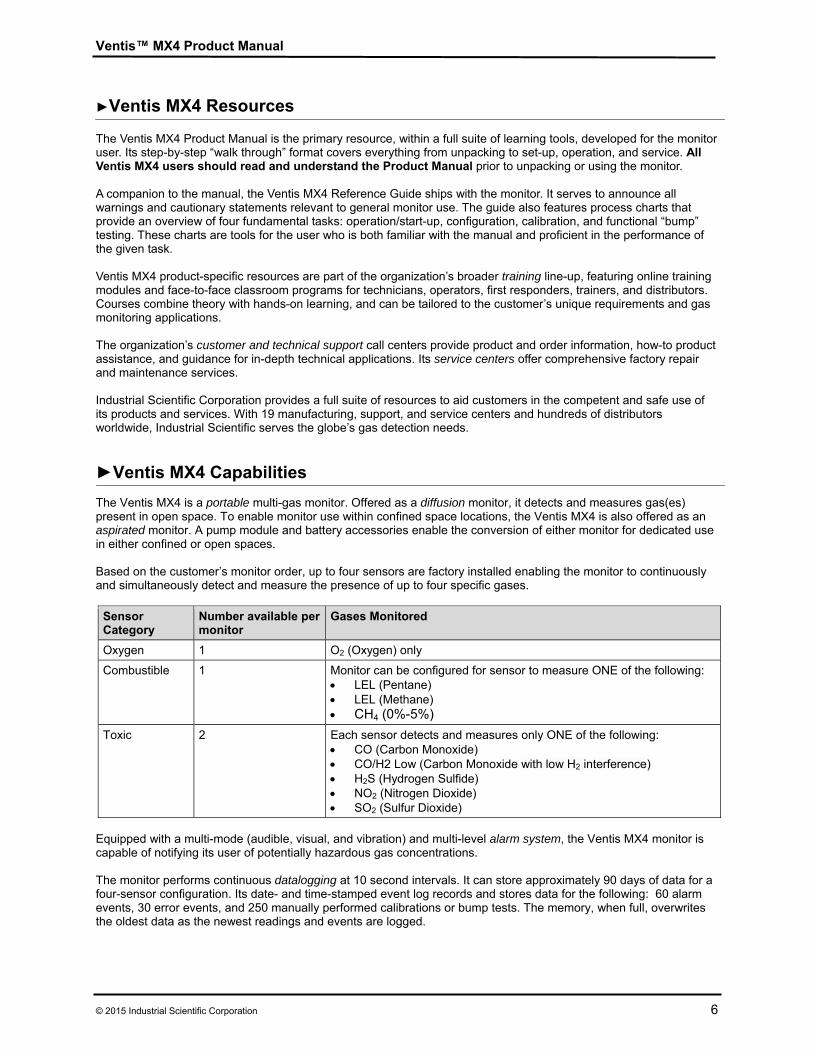
►Ventis MX4 Capabilities The Ventis MX4 is a portable multi-gas monitor. Offered as a diffusion monitor, it detects and measures gas(es) present in open space. To enable monitor use within confined space locations, the Ventis MX4 is also offered as an aspirated monitor. A pump module and battery accessories enable the conversion of either monitor for dedicated use in either confined or open spaces. Based on the customer’s monitor order, up to four sensors are factory installed enabling the monitor to continuously and simultaneously detect and measure the presence of up to four specific gases.
Sensor Category
Number available per monitor
Gases Monitored
Oxygen 1 O2 (Oxygen) only
Combustible 1 Monitor can be configured for sensor to measure ONE of the following: LEL (Pentane) LEL (Methane) CH4 (0%-5%)
Toxic 2 Each sensor detects and measures only ONE of the following: CO (Carbon Monoxide) CO/H2 Low (Carbon Monoxide with low H2 interference) H2S (Hydrogen Sulfide) NO2 (Nitrogen Dioxide) SO2 (Sulfur Dioxide)
Equipped with a multi-mode (audible, visual, and vibration) and multi-level alarm system, the Ventis MX4 monitor is capable of notifying its user of potentially hazardous gas concentrations. The monitor performs continuous datalogging at 10 second intervals. It can store approximately 90 days of data for a four-sensor configuration. Its date- and time-stamped event log records and stores data for the following: 60 alarm events, 30 error events, and 250 manually performed calibrations or bump tests. The memory, when full, overwrites the oldest data as the newest readings and events are logged.
Ventis™ MX4 Product Manual
7 © 2015 Industrial Scientific Corporation
The Ventis MX4 monitor functions as an independent device to monitor the environment for hazardous gas concentrations. It is compatible with products that charge, calibrate, bump test, read and record instrument data, protect, and otherwise enable or enhance use of the monitor and its data. For a complete list of these products, please refer to the manual section, Ventis MX4 Accessories and Parts.
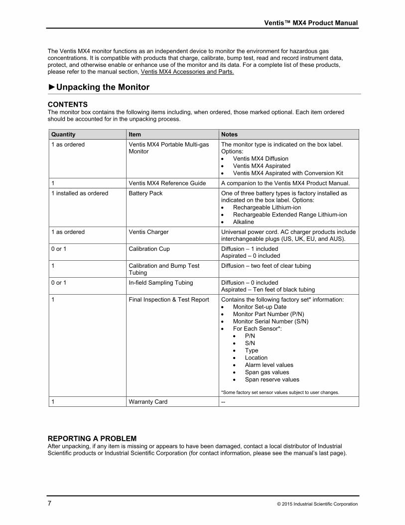
►Unpacking the Monitor CONTENTS The monitor box contains the following items including, when ordered, those marked optional. Each item ordered should be accounted for in the unpacking process.
Quantity Item Notes
1 as ordered Ventis MX4 Portable Multi-gas Monitor
The monitor type is indicated on the box label. Options: Ventis MX4 Diffusion Ventis MX4 Aspirated Ventis MX4 Aspirated with Conversion Kit
1 Ventis MX4 Reference Guide A companion to the Ventis MX4 Product Manual.
1 installed as ordered
Battery Pack
One of three battery types is factory installed as indicated on the box label. Options: Rechargeable Lithium-ion Rechargeable Extended Range Lithium-ion Alkaline
1 as ordered Ventis Charger Universal power cord. AC charger products include interchangeable plugs (US, UK, EU, and AUS).
0 or 1 Calibration Cup Diffusion – 1 included Aspirated – 0 included
1 Calibration and Bump Test Tubing
Diffusion – two feet of clear tubing
0 or 1 In-field Sampling Tubing Diffusion – 0 included Aspirated – Ten feet of black tubing
1 Final Inspection & Test Report Contains the following factory set* information: Monitor Set-up Date Monitor Part Number (P/N) Monitor Serial Number (S/N) For Each Sensor*:
P/N S/N Type Location Alarm level values Span gas values Span reserve values
*Some factory set sensor values subject to user changes.
1 Warranty Card --
REPORTING A PROBLEM After unpacking, if any item is missing or appears to have been damaged, contact a local distributor of Industrial Scientific products or Industrial Scientific Corporation (for contact information, please see the manual’s last page).
Ventis™ MX4 Product Manual
© 2015 Industrial Scientific Corporation 8
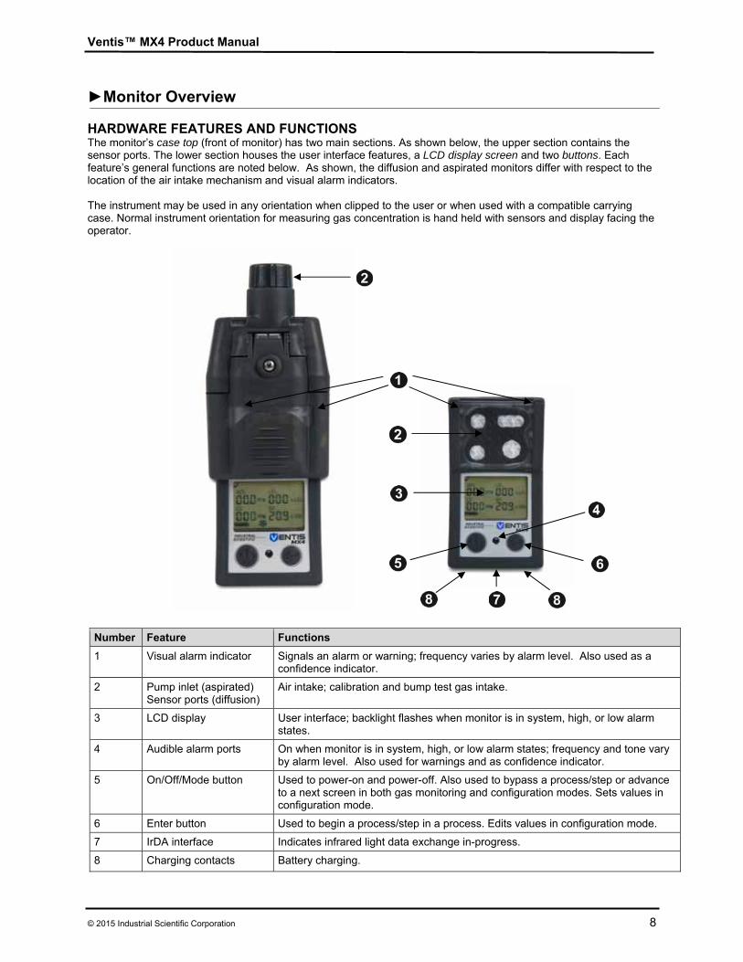
►Monitor Overview HARDWARE FEATURES AND FUNCTIONS The monitor’s case top (front of monitor) has two main sections. As shown below, the upper section contains the sensor ports. The lower section houses the user interface features, a LCD display screen and two buttons. Each feature’s general functions are noted below. As shown, the diffusion and aspirated monitors differ with respect to the location of the air intake mechanism and visual alarm indicators. The instrument may be used in any orientation when clipped to the user or when used with a compatible carrying case. Normal instrument orientation for measuring gas concentration is hand held with sensors and display facing the operator.
Number Feature Functions
1 Visual alarm indicator Signals an alarm or warning; frequency varies by alarm level. Also used as a confidence indicator.
2 Pump inlet (aspirated) Sensor ports (diffusion)
Air intake; calibration and bump test gas intake.
3 LCD display User interface; backlight flashes when monitor is in system, high, or low alarm states.
4 Audible alarm ports On when monitor is in system, high, or low alarm states; frequency and tone vary by alarm level. Also used for warnings and as confidence indicator.
5 On/Off/Mode button
Used to power-on and power-off. Also used to bypass a process/step or advance to a next screen in both gas monitoring and configuration modes. Sets values in configuration mode.
6 Enter button Used to begin a process/step in a process. Edits values in configuration mode.
7 IrDA interface Indicates infrared light data exchange in-progress.
8 Charging contacts Battery charging.
Ventis™ MX4 Product Manual
9 © 2015 Industrial Scientific Corporation
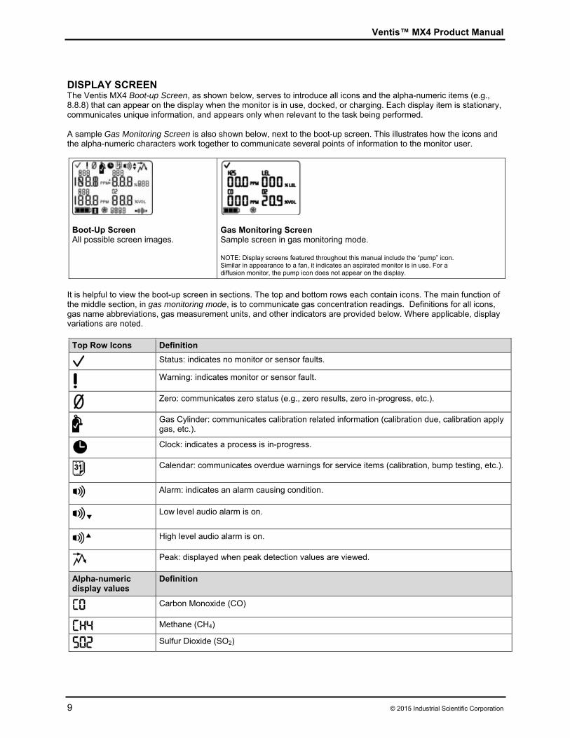
DISPLAY SCREEN The Ventis MX4 Boot-up Screen, as shown below, serves to introduce all icons and the alpha-numeric items (e.g., 8.8.8) that can appear on the display when the monitor is in use, docked, or charging. Each display item is stationary, communicates unique information, and appears only when relevant to the task being performed. A sample Gas Monitoring Screen is also shown below, next to the boot-up screen. This illustrates how the icons and the alpha-numeric characters work together to communicate several points of information to the monitor user.
Boot-Up Screen All possible screen images.
Gas Monitoring Screen Sample screen in gas monitoring mode. NOTE: Display screens featured throughout this manual include the “pump” icon. Similar in appearance to a fan, it indicates an aspirated monitor is in use. For a diffusion monitor, the pump icon does not appear on the display.
It is helpful to view the boot-up screen in sections. The top and bottom rows each contain icons. The main function of the middle section, in gas monitoring mode, is to communicate gas concentration readings. Definitions for all icons, gas name abbreviations, gas measurement units, and other indicators are provided below. Where applicable, display variations are noted.
Top Row Icons Definition
Status: indicates no monitor or sensor faults.
Warning: indicates monitor or sensor fault.
Zero: communicates zero status (e.g., zero results, zero in-progress, etc.).
Gas Cylinder: communicates calibration related information (calibration due, calibration apply gas, etc.).
Clock: indicates a process is in-progress.
Calendar: communicates overdue warnings for service items (calibration, bump testing, etc.).
Alarm: indicates an alarm causing condition.
Low level audio alarm is on.
High level audio alarm is on.
Peak: displayed when peak detection values are viewed.
Alpha-numeric display values
Definition
Carbon Monoxide (CO)
Methane (CH4)
Sulfur Dioxide (SO2)
Ventis™ MX4 Product Manual
© 2015 Industrial Scientific Corporation 10
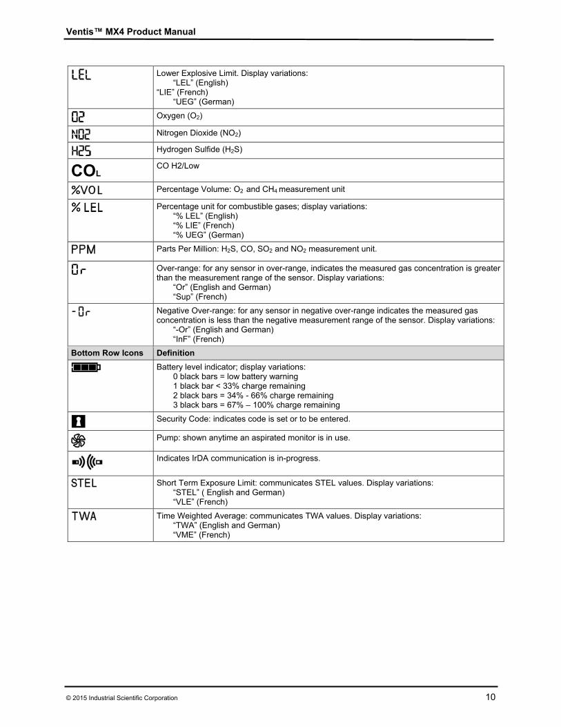
Lower Explosive Limit. Display variations: “LEL” (English)
“LIE” (French) “UEG” (German)
Oxygen (O2)
Nitrogen Dioxide (NO2)
Hydrogen Sulfide (H2S)
COL CO H2/Low
Percentage Volume: O2 and CH4 measurement unit
Percentage unit for combustible gases; display variations: “% LEL” (English) “% LIE” (French) “% UEG” (German)
Parts Per Million: H2S, CO, SO2 and NO2 measurement unit.
Over-range: for any sensor in over-range, indicates the measured gas concentration is greater than the measurement range of the sensor. Display variations:
“Or” (English and German) “Sup” (French)
Negative Over-range: for any sensor in negative over-range indicates the measured gas concentration is less than the negative measurement range of the sensor. Display variations:
“-Or” (English and German) “InF” (French)
Bottom Row Icons Definition
Battery level indicator; display variations: 0 black bars = low battery warning 1 black bar < 33% charge remaining 2 black bars = 34% - 66% charge remaining 3 black bars = 67% – 100% charge remaining
Security Code: indicates code is set or to be entered.
Pump: shown anytime an aspirated monitor is in use.
Indicates IrDA communication is in-progress.
Short Term Exposure Limit: communicates STEL values. Display variations: “STEL” ( English and German) “VLE” (French)
Time Weighted Average: communicates TWA values. Display variations: “TWA” (English and German) “VME” (French)
Ventis™ MX4 Product Manual
11 © 2015 Industrial Scientific Corporation
ALARMS NOTICE All monitor alarms and warnings should be taken seriously and responded to as stated in company safety
standards. Once initiated, an alarm will remain on while the alarm condition is present. For gas-related alarms, once the
detected gas concentration changes, the alarm indicators will change to reflect any new condition such as low-alarm gas, high-alarm gas, over-range gas, or no gas alarm.
When the latch alarm feature is enabled and the monitor goes into alarm, it will remain in alarm until the alarm condition no longer exists and the monitor user presses the ENTER button for one second. This applies only to gas-related alarms.
It is practical for the monitor user to be aware of the possible alarms prior to monitor set-up and use. The Ventis MX4 has four alarm and warning levels. A “system level” alarm generates the highest frequency tone and highest level visual and vibration signals. It is used to indicate such events as a pump or sensor failure. The “high” or “low” level audio alarms, in combination with visual and vibration indicators, turn on when gas concentration readings are over-range, high, or low. The lowest level indicator is a warning with beep patterns to indicate service needs (e.g., low battery or calibration due). The beep is also used as a confidence indicator when enabled. Alarm types and their alarm generating conditions are described below.
Display Description
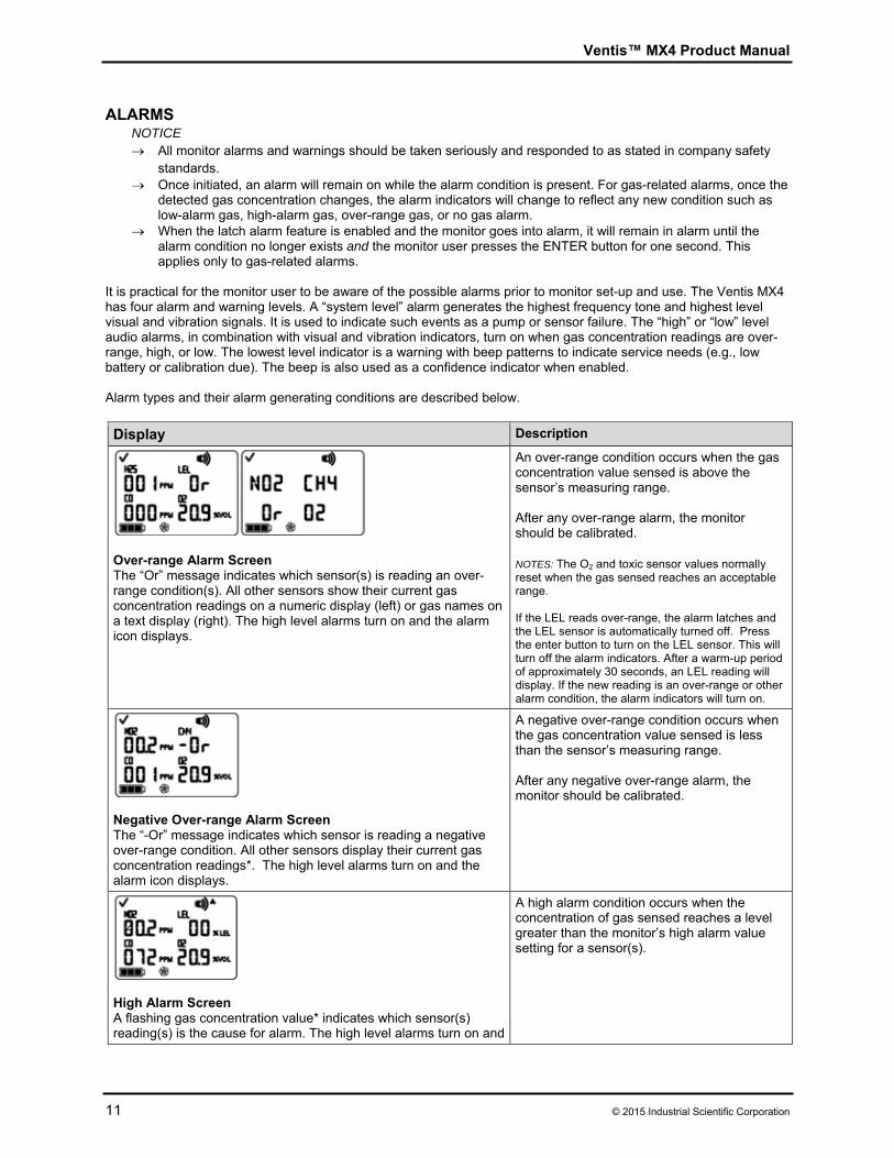
Over-range Alarm Screen The “Or” message indicates which sensor(s) is reading an over-range condition(s). All other sensors show their current gas concentration readings on a numeric display (left) or gas names on a text display (right). The high level alarms turn on and the alarm icon displays.
An over-range condition occurs when the gas concentration value sensed is above the sensor’s measuring range. After any over-range alarm, the monitor should be calibrated. NOTES: The O2 and toxic sensor values normally reset when the gas sensed reaches an acceptable range. If the LEL reads over-range, the alarm latches and the LEL sensor is automatically turned off. Press the enter button to turn on the LEL sensor. This will turn off the alarm indicators. After a warm-up period of approximately 30 seconds, an LEL reading will display. If the new reading is an over-range or other alarm condition, the alarm indicators will turn on.
Negative Over-range Alarm Screen The “-Or” message indicates which sensor is reading a negative over-range condition. All other sensors display their current gas concentration readings*. The high level alarms turn on and the alarm icon displays.
A negative over-range condition occurs when the gas concentration value sensed is less than the sensor’s measuring range. After any negative over-range alarm, the monitor should be calibrated.
High Alarm Screen A flashing gas concentration value* indicates which sensor(s) reading(s) is the cause for alarm. The high level alarms turn on and
A high alarm condition occurs when the concentration of gas sensed reaches a level greater than the monitor’s high alarm value setting for a sensor(s).
Ventis™ MX4 Product Manual
© 2015 Industrial Scientific Corporation 12
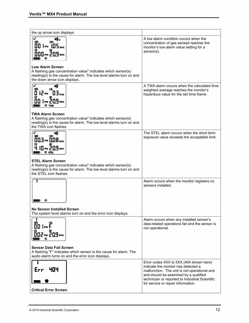
the up arrow icon displays.
Low Alarm Screen A flashing gas concentration value* indicates which sensor(s) reading(s) is the cause for alarm. The low level alarms turn on and the down arrow icon displays.
A low alarm condition occurs when the concentration of gas sensed reaches the monitor’s low alarm value setting for a sensor(s).
TWA Alarm Screen A flashing gas concentration value* indicates which sensor(s) reading(s) is the cause for alarm. The low level alarms turn on and the TWA icon flashes.
A TWA alarm occurs when the calculated time weighted average reaches the monitor’s hazardous value for the set time frame.
STEL Alarm Screen A flashing gas concentration value* indicates which sensor(s) reading(s) is the cause for alarm. The low level alarms turn on and the STEL icon flashes.
The STEL alarm occurs when the short term exposure value exceeds the acceptable limit.
No Sensor Installed Screen The system level alarms turn on and the error icon displays.
Alarm occurs when the monitor registers no sensors installed.
Sensor Data Fail Screen A flashing “F” indicates which sensor is the cause for alarm. The audio alarm turns on and the error icon displays.
Alarm occurs when any installed sensor’s data-related operations fail and the sensor is not operational.
Critical Error Screen
Error codes 4XX to 5XX (404 shown here) indicate the monitor has detected a malfunction. The unit is not operational and and should be examined by a qualified technician or reported to Industrial Scientific for service or repair information.
Ventis™ MX4 Product Manual
13 © 2015 Industrial Scientific Corporation
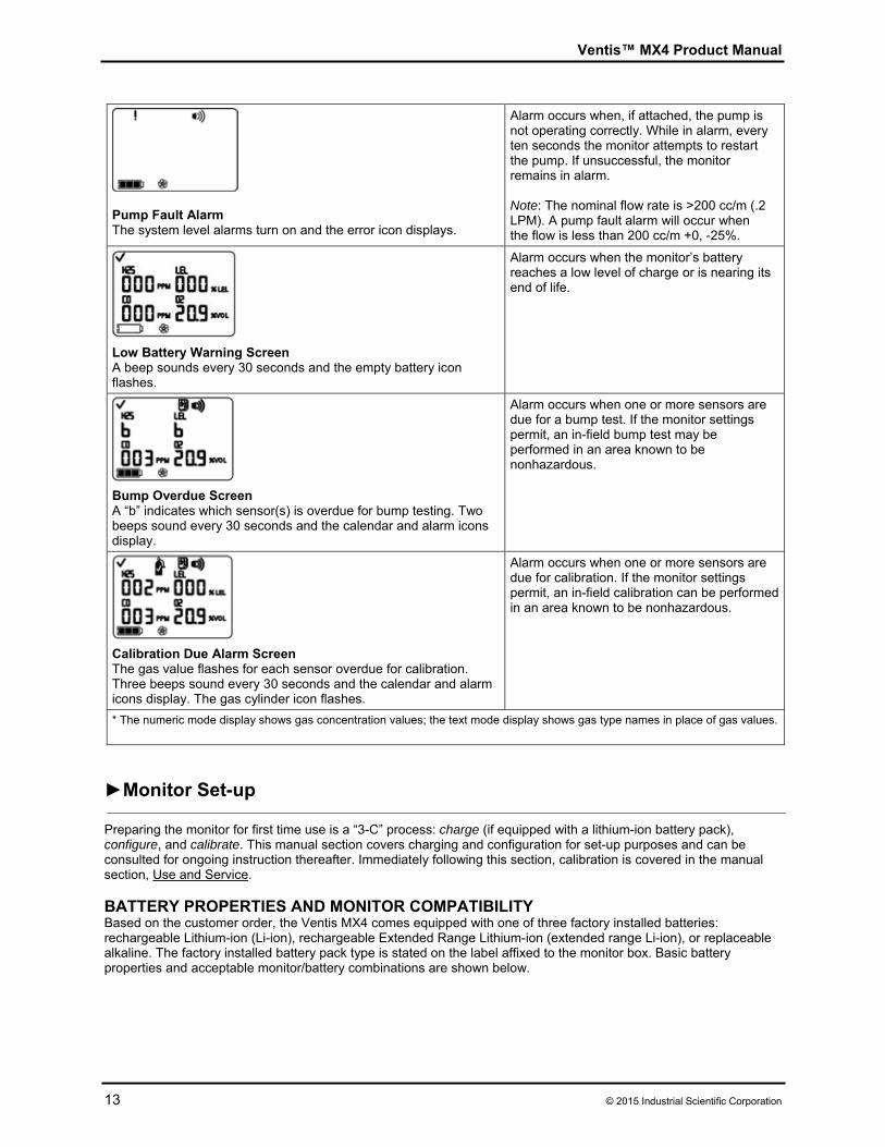
Pump Fault Alarm The system level alarms turn on and the error icon displays.
Alarm occurs when, if attached, the pump is not operating correctly. While in alarm, every ten seconds the monitor attempts to restart the pump. If unsuccessful, the monitor remains in alarm. Note: The nominal flow rate is >200 cc/m (.2 LPM). A pump fault alarm will occur when the flow is less than 200 cc/m +0, -25%.
Low Battery Warning Screen A beep sounds every 30 seconds and the empty battery icon flashes.
Alarm occurs when the monitor’s battery reaches a low level of charge or is nearing its end of life.
Bump Overdue Screen A “b” indicates which sensor(s) is overdue for bump testing. Two beeps sound every 30 seconds and the calendar and alarm icons display.
Alarm occurs when one or more sensors are due for a bump test. If the monitor settings permit, an in-field bump test may be performed in an area known to be nonhazardous.
Calibration Due Alarm Screen The gas value flashes for each sensor overdue for calibration. Three beeps sound every 30 seconds and the calendar and alarm icons display. The gas cylinder icon flashes.
Alarm occurs when one or more sensors are due for calibration. If the monitor settings permit, an in-field calibration can be performed in an area known to be nonhazardous.
* The numeric mode display shows gas concentration values; the text mode display shows gas type names in place of gas values.
►Monitor Set-up Preparing the monitor for first time use is a “3-C” process: charge (if equipped with a lithium-ion battery pack), configure, and calibrate. This manual section covers charging and configuration for set-up purposes and can be consulted for ongoing instruction thereafter. Immediately following this section, calibration is covered in the manual section, Use and Service. BATTERY PROPERTIES AND MONITOR COMPATIBILITY Based on the customer order, the Ventis MX4 comes equipped with one of three factory installed batteries: rechargeable Lithium-ion (Li-ion), rechargeable Extended Range Lithium-ion (extended range Li-ion), or replaceable alkaline. The factory installed battery pack type is stated on the label affixed to the monitor box. Basic battery properties and acceptable monitor/battery combinations are shown below.
Ventis™ MX4 Product Manual
© 2015 Industrial Scientific Corporation 14
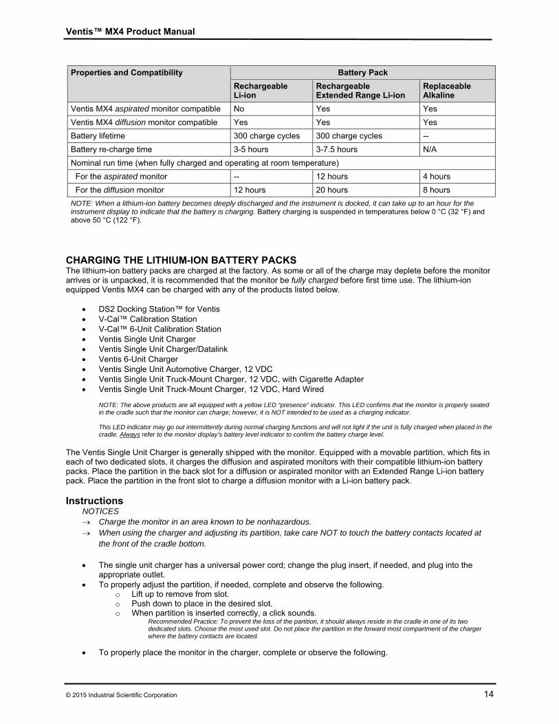
Properties and Compatibility Battery Pack
Rechargeable Li-ion
Rechargeable Extended Range Li-ion
ReplaceableAlkaline
Ventis MX4 aspirated monitor compatible No Yes Yes
Ventis MX4 diffusion monitor compatible Yes Yes Yes
Battery lifetime 300 charge cycles 300 charge cycles --
Battery re-charge time 3-5 hours 3-7.5 hours N/A
Nominal run time (when fully charged and operating at room temperature)
For the aspirated monitor -- 12 hours 4 hours
For the diffusion monitor 12 hours 20 hours 8 hours
NOTE: When a lithium-ion battery becomes deeply discharged and the instrument is docked, it can take up to an hour for the instrument display to indicate that the battery is charging. Battery charging is suspended in temperatures below 0 °C (32 °F) and above 50 °C (122 °F).
CHARGING THE LITHIUM-ION BATTERY PACKS The lithium-ion battery packs are charged at the factory. As some or all of the charge may deplete before the monitor arrives or is unpacked, it is recommended that the monitor be fully charged before first time use. The lithium-ion equipped Ventis MX4 can be charged with any of the products listed below.
DS2 Docking Station™ for Ventis V-Cal™ Calibration Station V-Cal™ 6-Unit Calibration Station Ventis Single Unit Charger Ventis Single Unit Charger/Datalink Ventis 6-Unit Charger Ventis Single Unit Automotive Charger, 12 VDC Ventis Single Unit Truck-Mount Charger, 12 VDC, with Cigarette Adapter Ventis Single Unit Truck-Mount Charger, 12 VDC, Hard Wired
NOTE: The above products are all equipped with a yellow LED “presence” indicator. This LED confirms that the monitor is properly seated in the cradle such that the monitor can charge; however, it is NOT intended to be used as a charging indicator. This LED indicator may go out intermittently during normal charging functions and will not light if the unit is fully charged when placed in the cradle. Always refer to the monitor display’s battery level indicator to confirm the battery charge level.
The Ventis Single Unit Charger is generally shipped with the monitor. Equipped with a movable partition, which fits in each of two dedicated slots, it charges the diffusion and aspirated monitors with their compatible lithium-ion battery packs. Place the partition in the back slot for a diffusion or aspirated monitor with an Extended Range Li-ion battery pack. Place the partition in the front slot to charge a diffusion monitor with a Li-ion battery pack. Instructions
NOTICES Charge the monitor in an area known to be nonhazardous. When using the charger and adjusting its partition, take care NOT to touch the battery contacts located at
the front of the cradle bottom.
The single unit charger has a universal power cord; change the plug insert, if needed, and plug into the appropriate outlet.
To properly adjust the partition, if needed, complete and observe the following. o Lift up to remove from slot. o Push down to place in the desired slot. o When partition is inserted correctly, a click sounds.
Recommended Practice: To prevent the loss of the partition, it should always reside in the cradle in one of its two dedicated slots. Choose the most used slot. Do not place the partition in the forward most compartment of the charger where the battery contacts are located.
To properly place the monitor in the charger, complete or observe the following.
Ventis™ MX4 Product Manual
15 © 2015 Industrial Scientific Corporation
o The monitor’s display side faces the user. o The charging contacts on the monitor bottom meet the contact pins inside the charger’s cradle. o Refer to the monitor’s battery icon to confirm the battery charge level.
If the battery is less than fully charged, the monitor displays the battery icon (flashing empty to full, repeatedly).
If the battery is fully charged, the monitor displays a full battery icon.
POWER-ON AND -OFF To power-on the Ventis MX4, press ON/OFF/MODE and hold for three to five seconds. During the first ten to15 seconds the monitor is on, its firmware completes internal tests and the user sees or hears what is described and shown below. Following this initialization phase, a countdown screen displays. During this 20-second countdown, the monitor user can enter configuration mode to manually adjust monitor settings.
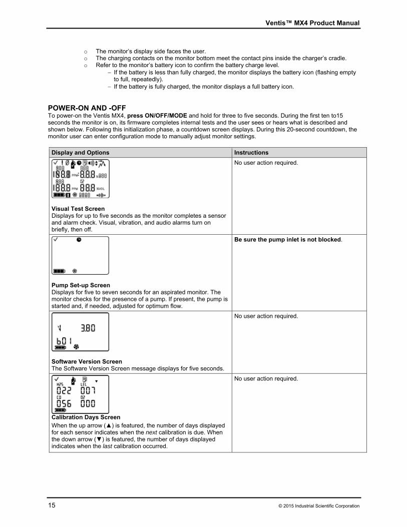
Display and Options Instructions
Visual Test Screen Displays for up to five seconds as the monitor completes a sensor and alarm check. Visual, vibration, and audio alarms turn on briefly, then off.
No user action required.
Pump Set-up Screen Displays for five to seven seconds for an aspirated monitor. The monitor checks for the presence of a pump. If present, the pump is started and, if needed, adjusted for optimum flow.
Be sure the pump inlet is not blocked.
Software Version Screen The Software Version Screen message displays for five seconds.
No user action required.
Calibration Days Screen When the up arrow (▲) is featured, the number of days displayed for each sensor indicates when the next calibration is due. When the down arrow (▼) is featured, the number of days displayed indicates when the last calibration occurred.
No user action required.
Ventis™ MX4 Product Manual
© 2015 Industrial Scientific Corporation 16
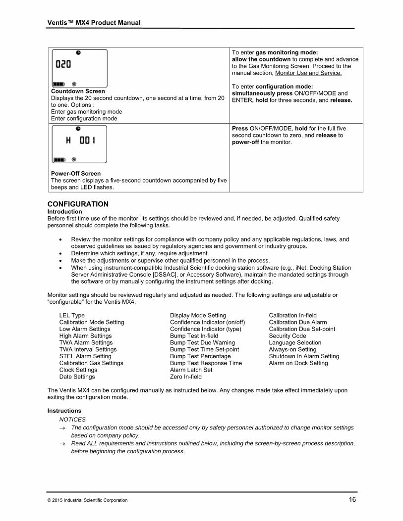
Countdown Screen Displays the 20 second countdown, one second at a time, from 20 to one. Options : Enter gas monitoring mode Enter configuration mode
To enter gas monitoring mode: allow the countdown to complete and advance to the Gas Monitoring Screen. Proceed to the manual section, Monitor Use and Service. To enter configuration mode: simultaneously press ON/OFF/MODE and ENTER, hold for three seconds, and release.
Power-Off Screen The screen displays a five-second countdown accompanied by five beeps and LED flashes.
Press ON/OFF/MODE, hold for the full five second countdown to zero, and release to power-off the monitor.
CONFIGURATION Introduction Before first time use of the monitor, its settings should be reviewed and, if needed, be adjusted. Qualified safety personnel should complete the following tasks.
Review the monitor settings for compliance with company policy and any applicable regulations, laws, and
observed guidelines as issued by regulatory agencies and government or industry groups. Determine which settings, if any, require adjustment. Make the adjustments or supervise other qualified personnel in the process. When using instrument-compatible Industrial Scientific docking station software (e.g., iNet, Docking Station
Server Administrative Console [DSSAC], or Accessory Software), maintain the mandated settings through the software or by manually configuring the instrument settings after docking.
Monitor settings should be reviewed regularly and adjusted as needed. The following settings are adjustable or “configurable" for the Ventis MX4.
LEL Type Calibration Mode Setting Low Alarm Settings High Alarm Settings TWA Alarm Settings TWA Interval Settings STEL Alarm Setting Calibration Gas Settings Clock Settings Date Settings
Display Mode Setting Confidence Indicator (on/off) Confidence Indicator (type) Bump Test In-field Bump Test Due Warning Bump Test Time Set-point Bump Test Percentage Bump Test Response Time Alarm Latch Set Zero In-field
Calibration In-field Calibration Due Alarm Calibration Due Set-point Security Code Language Selection Always-on Setting Shutdown In Alarm Setting Alarm on Dock Setting
The Ventis MX4 can be configured manually as instructed below. Any changes made take effect immediately upon exiting the configuration mode. Instructions
NOTICES The configuration mode should be accessed only by safety personnel authorized to change monitor settings
based on company policy. Read ALL requirements and instructions outlined below, including the screen-by-screen process description,
before beginning the configuration process.

Ventis™ MX4 Product Manual
17 © 2015 Industrial Scientific Corporation
The configuration mode can be entered during the 20-second countdown of the power-on process. During the countdown, simultaneously press ON/OFF/MODE and ENTER, hold for three seconds, and release to enter configuration mode. (While in the configuration mode, the same button presses cause the monitor to exit configuration). Each configuration screen times out after 30 seconds and the monitor enters gas monitoring mode. To re-enter the configuration mode, power-off the monitor, then power-on and repeat the entry process. Throughout the configuration process, the main functions of the two buttons are as follows.
The ENTER button is used to edit values. It is also used, where noted, to begin a process or a step in a process.
The ON/OFF/MODE button is used to set the value. Where noted, it is also used to bypass a process or step in a process, or to advance to the next configuration screen.
The first screen to display in configuration mode depends on three things:
security code setting, the presence or absence of the China MA feature, and the presence or absence of an LEL sensor. If the security code setting is 000, the security feature is disabled and the Enter Security Code Screen does NOT appear. If the security code is NOT 000, the security feature is enabled and the monitor displays the Enter Security Code Screen. The monitor next checks for the presence of a China MA mining feature. If this feature is operational, the monitor displays the Zero Initiate Screen. If the China MA mining feature is NOT operational, the monitor then checks for an installed LEL sensor. If installed, the monitor displays the LEL Type Screen. If no LEL sensor is installed, the monitor displays the Zero Initiate Screen.
Configuration Process
Display and Options Instructions
Enter Security Code Screen The presence of this screen indicates an enabled security feature.
Press ENTER to edit the value, if needed; press repeatedly or hold down to speed the increment pace to reach the valid security code. Press ON/OFF/MODE to enter configuration mode and arrive at the next applicable screen.
LEL Type Set Screen Options LEL CH4
Press ENTER to edit the value, if needed.Press ON/OFF/MODE to set the value and advance to the Zero Initiate Screen. NOTE: If the LEL type is changed, the sensor goes into calibration fail mode. A full calibration is required before the monitor can be used and is accessible from the next screen in the configuration process, the Zero Initiate Screen. For complete calibration instructions, proceed to the manual section, Zero, Calibration, and Bump Testing.
Ventis™ MX4 Product Manual
© 2015 Industrial Scientific Corporation 18
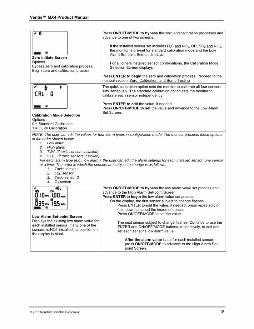
Zero Initiate Screen Options Bypass zero and calibration process. Begin zero and calibration process.
Press ON/OFF/MODE to bypass the zero and calibration processes and advance to one of two screens.
If the installed sensor set includes H2S and NO2, OR, SO2 and NO2, the monitor is pre-set for standard calibration mode and the Low Alarm Set-point Screen displays.
For all others installed sensor combinations, the Calibration Mode Selection Screen displays.
Press ENTER to begin the zero and calibration process. Proceed to the manual section, Zero, Calibration, and Bump Testing
Calibration Mode Selection Options 0 = Standard Calibration 1 = Quick Calibration
The quick calibration option sets the monitor to calibrate all four sensors simultaneously. The standard calibration option sets the monitor to calibrate each sensor independently.
Press ENTER to edit the value, if needed. Press ON/OFF/MODE to set the value and advance to the Low Alarm Set Screen.
NOTE: The user can edit the values for four alarm types in configuration mode. The monitor presents these options in the order shown below.
1. Low alarm 2. High alarm 3. TWA (if toxic sensors installed) 4. STEL (if toxic sensors installed) For each alarm type (e.g., low alarm), the user can edit the alarm settings for each installed sensor, one sensor at a time. The order in which the sensors are subject to change is as follows.
1. Toxic sensor 1 2. LEL sensor 3. Toxic sensor 2 4. O2 sensor
Low Alarm Set-point Screen Displays the existing low alarm value for each installed sensor. If any one of the sensors is NOT installed, its position on the display is blank.
Press ON/OFF/MODE to bypass the low alarm value set process and advance to the High Alarm Set-point Screen. Press ENTER to begin the low alarm value set process.
On the display, the first sensor subject to change flashes. Press ENTER to edit the value, if needed; press repeatedly or hold down to speed the increment pace. Press ON/OFF/MODE to set the value.
The next sensor subject to change flashes. Continue to use the ENTER and ON/OFF/MODE buttons, respectively, to edit and set each sensor’s low alarm value.
After the alarm value is set for each installed sensor, press ON/OFF/MODE to advance to the High Alarm Set-point Screen.
Ventis™ MX4 Product Manual
19 © 2015 Industrial Scientific Corporation
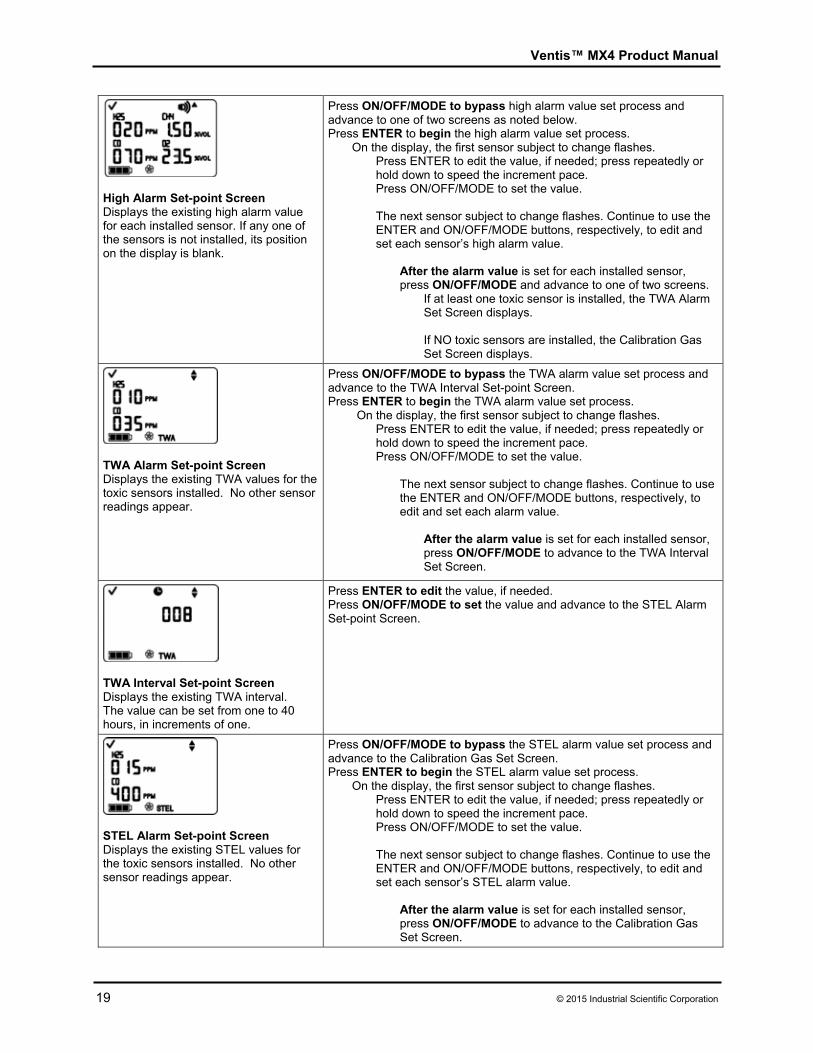
High Alarm Set-point Screen Displays the existing high alarm value for each installed sensor. If any one of the sensors is not installed, its position on the display is blank.
Press ON/OFF/MODE to bypass high alarm value set process and advance to one of two screens as noted below. Press ENTER to begin the high alarm value set process.
On the display, the first sensor subject to change flashes. Press ENTER to edit the value, if needed; press repeatedly or hold down to speed the increment pace. Press ON/OFF/MODE to set the value.
The next sensor subject to change flashes. Continue to use the ENTER and ON/OFF/MODE buttons, respectively, to edit and set each sensor’s high alarm value.
After the alarm value is set for each installed sensor, press ON/OFF/MODE and advance to one of two screens.
If at least one toxic sensor is installed, the TWA Alarm Set Screen displays.
If NO toxic sensors are installed, the Calibration Gas Set Screen displays.
TWA Alarm Set-point Screen Displays the existing TWA values for the toxic sensors installed. No other sensor readings appear.
Press ON/OFF/MODE to bypass the TWA alarm value set process and advance to the TWA Interval Set-point Screen. Press ENTER to begin the TWA alarm value set process.
On the display, the first sensor subject to change flashes. Press ENTER to edit the value, if needed; press repeatedly or hold down to speed the increment pace. Press ON/OFF/MODE to set the value.
The next sensor subject to change flashes. Continue to use the ENTER and ON/OFF/MODE buttons, respectively, to edit and set each alarm value.
After the alarm value is set for each installed sensor, press ON/OFF/MODE to advance to the TWA Interval Set Screen.
TWA Interval Set-point Screen Displays the existing TWA interval. The value can be set from one to 40 hours, in increments of one.
Press ENTER to edit the value, if needed. Press ON/OFF/MODE to set the value and advance to the STEL Alarm Set-point Screen.
STEL Alarm Set-point Screen Displays the existing STEL values for the toxic sensors installed. No other sensor readings appear.
Press ON/OFF/MODE to bypass the STEL alarm value set process and advance to the Calibration Gas Set Screen. Press ENTER to begin the STEL alarm value set process.
On the display, the first sensor subject to change flashes. Press ENTER to edit the value, if needed; press repeatedly or hold down to speed the increment pace. Press ON/OFF/MODE to set the value.
The next sensor subject to change flashes. Continue to use the ENTER and ON/OFF/MODE buttons, respectively, to edit and set each sensor’s STEL alarm value.
After the alarm value is set for each installed sensor, press ON/OFF/MODE to advance to the Calibration Gas Set Screen.
Ventis™ MX4 Product Manual
© 2015 Industrial Scientific Corporation 20
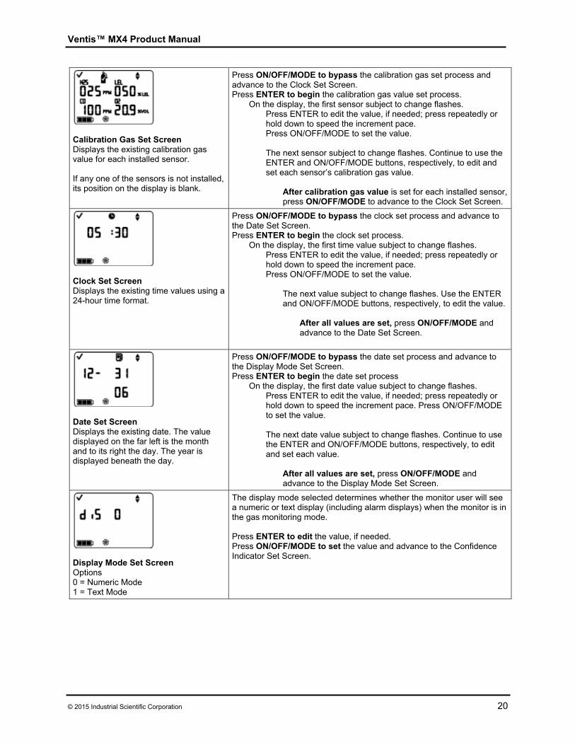
Calibration Gas Set Screen Displays the existing calibration gas value for each installed sensor. If any one of the sensors is not installed, its position on the display is blank.
Press ON/OFF/MODE to bypass the calibration gas set process and advance to the Clock Set Screen. Press ENTER to begin the calibration gas value set process.
On the display, the first sensor subject to change flashes. Press ENTER to edit the value, if needed; press repeatedly or hold down to speed the increment pace. Press ON/OFF/MODE to set the value.
The next sensor subject to change flashes. Continue to use the ENTER and ON/OFF/MODE buttons, respectively, to edit and set each sensor’s calibration gas value.
After calibration gas value is set for each installed sensor, press ON/OFF/MODE to advance to the Clock Set Screen.
Clock Set Screen Displays the existing time values using a 24-hour time format.
Press ON/OFF/MODE to bypass the clock set process and advance to the Date Set Screen. Press ENTER to begin the clock set process.
On the display, the first time value subject to change flashes. Press ENTER to edit the value, if needed; press repeatedly or hold down to speed the increment pace. Press ON/OFF/MODE to set the value.
The next value subject to change flashes. Use the ENTER and ON/OFF/MODE buttons, respectively, to edit the value.
After all values are set, press ON/OFF/MODE and advance to the Date Set Screen.
Date Set Screen Displays the existing date. The value displayed on the far left is the month and to its right the day. The year is displayed beneath the day.
Press ON/OFF/MODE to bypass the date set process and advance to the Display Mode Set Screen. Press ENTER to begin the date set process
On the display, the first date value subject to change flashes. Press ENTER to edit the value, if needed; press repeatedly or hold down to speed the increment pace. Press ON/OFF/MODE to set the value. The next date value subject to change flashes. Continue to use the ENTER and ON/OFF/MODE buttons, respectively, to edit and set each value.
After all values are set, press ON/OFF/MODE and advance to the Display Mode Set Screen.
Display Mode Set Screen Options 0 = Numeric Mode 1 = Text Mode
The display mode selected determines whether the monitor user will see a numeric or text display (including alarm displays) when the monitor is in the gas monitoring mode. Press ENTER to edit the value, if needed. Press ON/OFF/MODE to set the value and advance to the Confidence Indicator Set Screen.
Ventis™ MX4 Product Manual
21 © 2015 Industrial Scientific Corporation
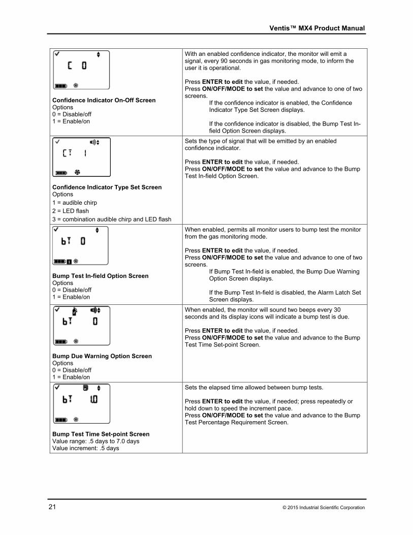
Confidence Indicator On-Off Screen Options 0 = Disable/off 1 = Enable/on
With an enabled confidence indicator, the monitor will emit a signal, every 90 seconds in gas monitoring mode, to inform the user it is operational. Press ENTER to edit the value, if needed. Press ON/OFF/MODE to set the value and advance to one of two screens.
If the confidence indicator is enabled, the Confidence Indicator Type Set Screen displays. If the confidence indicator is disabled, the Bump Test In-field Option Screen displays.
Confidence Indicator Type Set Screen Options 1 = audible chirp 2 = LED flash 3 = combination audible chirp and LED flash
Sets the type of signal that will be emitted by an enabled confidence indicator. Press ENTER to edit the value, if needed. Press ON/OFF/MODE to set the value and advance to the Bump Test In-field Option Screen.
Bump Test In-field Option Screen Options 0 = Disable/off 1 = Enable/on
When enabled, permits all monitor users to bump test the monitor from the gas monitoring mode. Press ENTER to edit the value, if needed. Press ON/OFF/MODE to set the value and advance to one of two screens.
If Bump Test In-field is enabled, the Bump Due Warning Option Screen displays.
If the Bump Test In-field is disabled, the Alarm Latch Set Screen displays.
Bump Due Warning Option Screen Options 0 = Disable/off 1 = Enable/on
When enabled, the monitor will sound two beeps every 30 seconds and its display icons will indicate a bump test is due. Press ENTER to edit the value, if needed. Press ON/OFF/MODE to set the value and advance to the Bump Test Time Set-point Screen.
Bump Test Time Set-point Screen Value range: .5 days to 7.0 days Value increment: .5 days
Sets the elapsed time allowed between bump tests. Press ENTER to edit the value, if needed; press repeatedly or hold down to speed the increment pace. Press ON/OFF/MODE to set the value and advance to the Bump Test Percentage Requirement Screen.
Ventis™ MX4 Product Manual
© 2015 Industrial Scientific Corporation 22
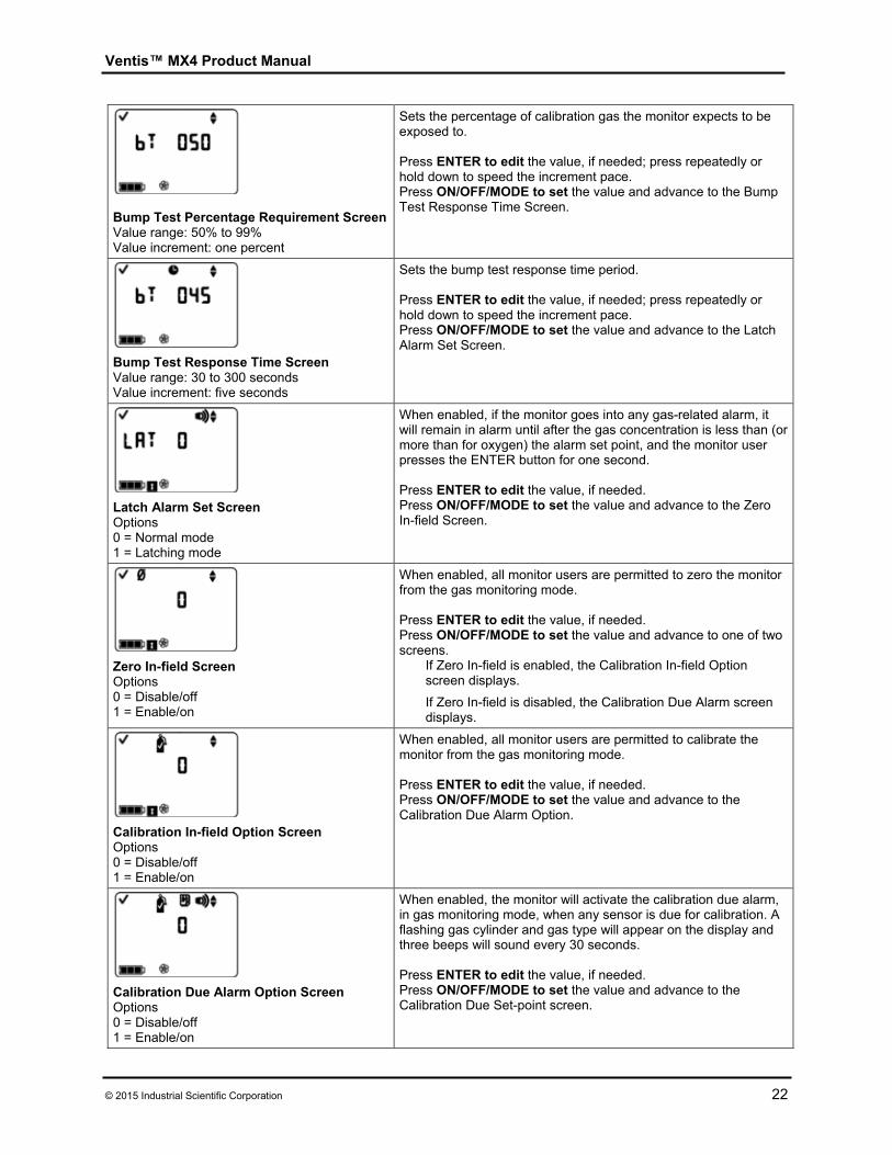
Bump Test Percentage Requirement ScreenValue range: 50% to 99% Value increment: one percent
Sets the percentage of calibration gas the monitor expects to be exposed to. Press ENTER to edit the value, if needed; press repeatedly or hold down to speed the increment pace. Press ON/OFF/MODE to set the value and advance to the Bump Test Response Time Screen.
Bump Test Response Time Screen Value range: 30 to 300 seconds Value increment: five seconds
Sets the bump test response time period. Press ENTER to edit the value, if needed; press repeatedly or hold down to speed the increment pace. Press ON/OFF/MODE to set the value and advance to the Latch Alarm Set Screen.
Latch Alarm Set Screen Options 0 = Normal mode 1 = Latching mode
When enabled, if the monitor goes into any gas-related alarm, it will remain in alarm until after the gas concentration is less than (or more than for oxygen) the alarm set point, and the monitor user presses the ENTER button for one second. Press ENTER to edit the value, if needed. Press ON/OFF/MODE to set the value and advance to the Zero In-field Screen.
Zero In-field Screen Options 0 = Disable/off 1 = Enable/on
When enabled, all monitor users are permitted to zero the monitor from the gas monitoring mode. Press ENTER to edit the value, if needed. Press ON/OFF/MODE to set the value and advance to one of two screens.
If Zero In-field is enabled, the Calibration In-field Option screen displays.
If Zero In-field is disabled, the Calibration Due Alarm screen displays.
Calibration In-field Option Screen Options 0 = Disable/off 1 = Enable/on
When enabled, all monitor users are permitted to calibrate the monitor from the gas monitoring mode. Press ENTER to edit the value, if needed. Press ON/OFF/MODE to set the value and advance to the Calibration Due Alarm Option.
Calibration Due Alarm Option Screen Options 0 = Disable/off 1 = Enable/on
When enabled, the monitor will activate the calibration due alarm, in gas monitoring mode, when any sensor is due for calibration. A flashing gas cylinder and gas type will appear on the display and three beeps will sound every 30 seconds. Press ENTER to edit the value, if needed. Press ON/OFF/MODE to set the value and advance to the Calibration Due Set-point screen.
Ventis™ MX4 Product Manual
23 © 2015 Industrial Scientific Corporation
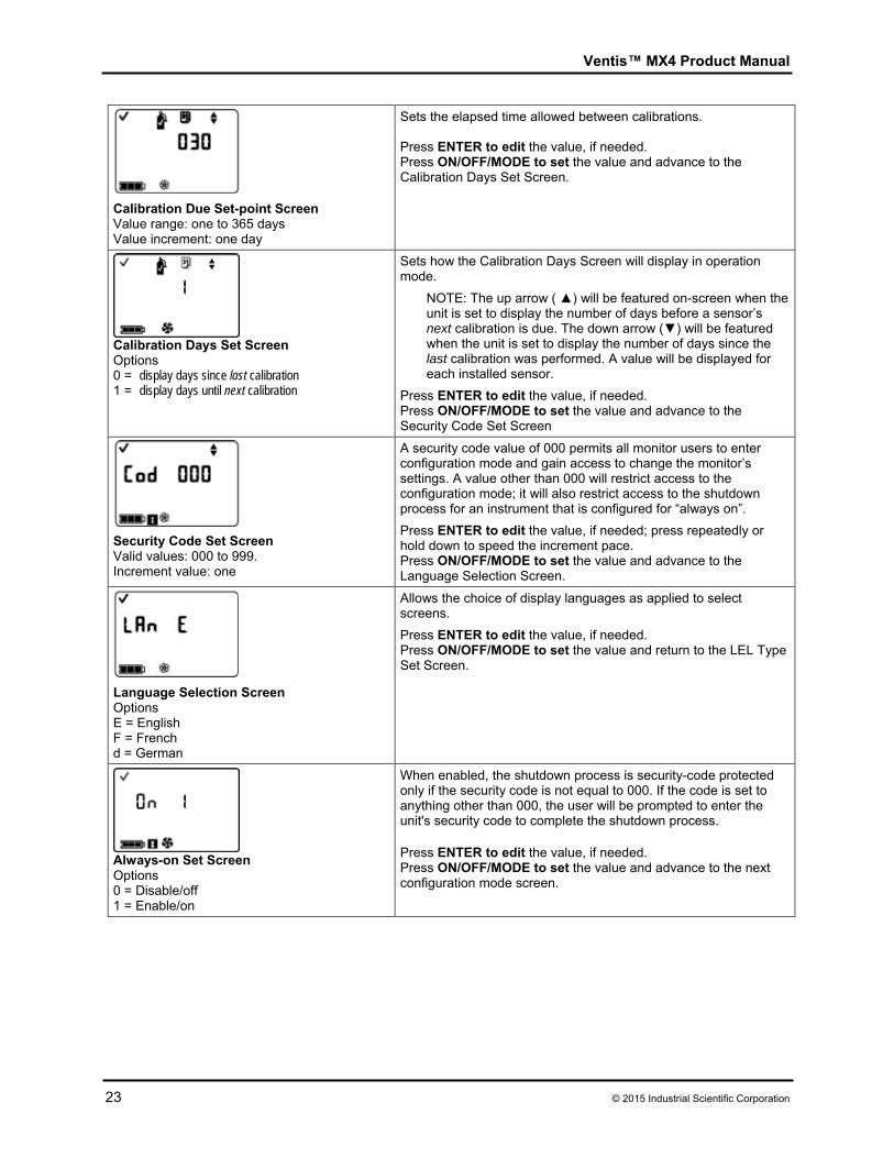
Calibration Due Set-point Screen Value range: one to 365 days Value increment: one day
Sets the elapsed time allowed between calibrations. Press ENTER to edit the value, if needed. Press ON/OFF/MODE to set the value and advance to the Calibration Days Set Screen.
Calibration Days Set Screen Options 0 = display days since last calibration 1 = display days until next calibration
Sets how the Calibration Days Screen will display in operation mode.
NOTE: The up arrow ( ▲) will be featured on-screen when the unit is set to display the number of days before a sensor’s next calibration is due. The down arrow (▼) will be featured when the unit is set to display the number of days since the last calibration was performed. A value will be displayed for each installed sensor.
Press ENTER to edit the value, if needed. Press ON/OFF/MODE to set the value and advance to the Security Code Set Screen
Security Code Set Screen Valid values: 000 to 999. Increment value: one
A security code value of 000 permits all monitor users to enter configuration mode and gain access to change the monitor’s settings. A value other than 000 will restrict access to the configuration mode; it will also restrict access to the shutdown process for an instrument that is configured for “always on”.
Press ENTER to edit the value, if needed; press repeatedly or hold down to speed the increment pace. Press ON/OFF/MODE to set the value and advance to the Language Selection Screen.
Language Selection Screen Options E = English F = French d = German
Allows the choice of display languages as applied to select screens.
Press ENTER to edit the value, if needed. Press ON/OFF/MODE to set the value and return to the LEL Type Set Screen.
Always-on Set Screen Options 0 = Disable/off 1 = Enable/on
When enabled, the shutdown process is security-code protected only if the security code is not equal to 000. If the code is set to anything other than 000, the user will be prompted to enter the unit's security code to complete the shutdown process. Press ENTER to edit the value, if needed. Press ON/OFF/MODE to set the value and advance to the next configuration mode screen.
Ventis™ MX4 Product Manual
© 2015 Industrial Scientific Corporation 24
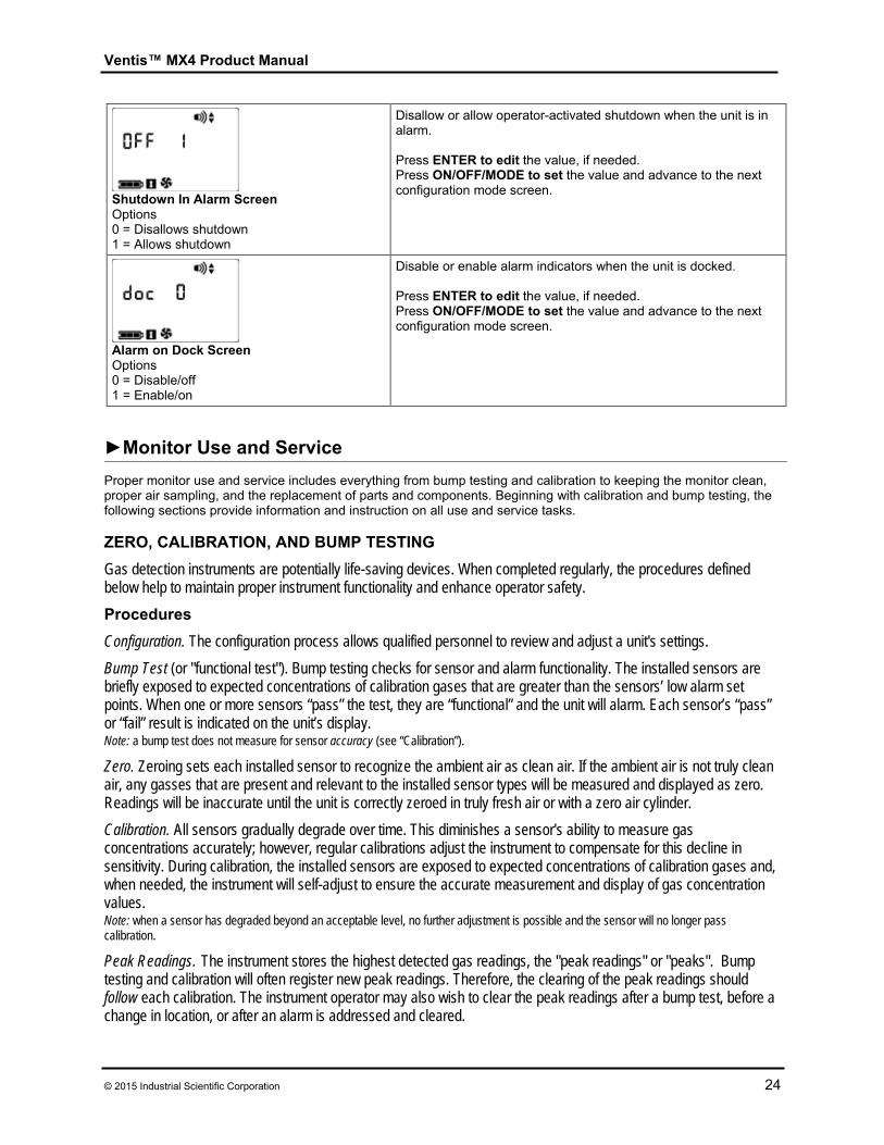
Shutdown In Alarm Screen Options 0 = Disallows shutdown 1 = Allows shutdown
Disallow or allow operator-activated shutdown when the unit is in alarm. Press ENTER to edit the value, if needed. Press ON/OFF/MODE to set the value and advance to the next configuration mode screen.
Alarm on Dock Screen Options 0 = Disable/off 1 = Enable/on
Disable or enable alarm indicators when the unit is docked. Press ENTER to edit the value, if needed. Press ON/OFF/MODE to set the value and advance to the next configuration mode screen.
►Monitor Use and Service Proper monitor use and service includes everything from bump testing and calibration to keeping the monitor clean, proper air sampling, and the replacement of parts and components. Beginning with calibration and bump testing, the following sections provide information and instruction on all use and service tasks. ZERO, CALIBRATION, AND BUMP TESTING
Gas detection instruments are potentially life-saving devices. When completed regularly, the procedures defined below help to maintain proper instrument functionality and enhance operator safety.
Procedures
Configuration. The configuration process allows qualified personnel to review and adjust a unit's settings.
Bump Test (or "functional test"). Bump testing checks for sensor and alarm functionality. The installed sensors are briefly exposed to expected concentrations of calibration gases that are greater than the sensors’ low alarm set points. When one or more sensors “pass” the test, they are “functional” and the unit will alarm. Each sensor’s “pass” or “fail” result is indicated on the unit’s display. Note: a bump test does not measure for sensor accuracy (see “Calibration”).
Zero. Zeroing sets each installed sensor to recognize the ambient air as clean air. If the ambient air is not truly clean air, any gasses that are present and relevant to the installed sensor types will be measured and displayed as zero. Readings will be inaccurate until the unit is correctly zeroed in truly fresh air or with a zero air cylinder.
Calibration. All sensors gradually degrade over time. This diminishes a sensor's ability to measure gas concentrations accurately; however, regular calibrations adjust the instrument to compensate for this decline in sensitivity. During calibration, the installed sensors are exposed to expected concentrations of calibration gases and, when needed, the instrument will self-adjust to ensure the accurate measurement and display of gas concentration values. Note: when a sensor has degraded beyond an acceptable level, no further adjustment is possible and the sensor will no longer pass calibration.
Peak Readings. The instrument stores the highest detected gas readings, the "peak readings" or "peaks". Bump testing and calibration will often register new peak readings. Therefore, the clearing of the peak readings should follow each calibration. The instrument operator may also wish to clear the peak readings after a bump test, before a change in location, or after an alarm is addressed and cleared.
Ventis™ MX4 Product Manual
25 © 2015 Industrial Scientific Corporation
Note: The peak readings and the data log readings are stored independently of one another; therefore, clearing the peak reading does not affect the data log. Powering the instrument off or changing its battery does not affect the peak reading. These checks and balances help promote operator safety, and serve to contain the peak readings in a "black-box" manner. In the event of a gas-related incident, this black-box record can be useful to the safety team or a prospective investigator.
Recommendations
Industrial Scientific Corporation (ISC) minimum frequency recommendations for each procedure are summarized in the table below. These recommendations are based on field data, safe work procedures, industry best practices, and regulatory standards to help ensure worker safety. Industrial Scientific is not responsible for setting safety practices and policies. These policies may be affected by the directives and recommendations of regulatory groups, environmental conditions, operating conditions, instrument use patterns and exposure to gas, and other factors.
Procedure ISC Recommended minimum frequency
Configuration Before first use and as needed thereafter.
Calibrationa Before first use and monthly thereafter.
Bump testb Prior to each day’s use. aBetween regular calibrations, ISC also recommends a calibration be performed immediately following each of these incidences: the unit falls, is dropped, or experiences another significant impact; is exposed to water; fails a bump test; or has been repeatedly exposed to an over-range (positive or negative) gas concentration. A calibration is also recommended after the installation of a new (or replacement) sensor. bIf conditions do not permit daily testing, bump tests may be done less frequently based on company safety policy. Note: The use of calibration gases not provided by ISC may void product warranties and limit potential liability claims.
General information The zero, calibration, and bump testing tasks are in-field enabled or in-field disabled in the configuration process. This permits or denies access to these functions from the gas monitoring mode. When any of these options is enabled, it is accessible to all monitor users. In gas monitoring mode, a series of presses on the ON/OFF/MODE button gives the user access to the following screens and processes in the order shown.
Gas Monitoring Screen Days Since Calibration Zero Initiate (if in-field enabled)
o Calibration Apply Gas Screen (if in-field enabled) Bump Test Initiate (if in-field enabled) Peak Readings TWA Readings STEL Readings
The monitor is capable of performing two types of calibration, and this option is set in configuration mode. The calibration type selected also determines the monitor’s bump test type. With a “quick” calibration, the monitor is set to calibrate and bump test all installed sensors simultaneously. With a “standard” calibration setting, these tasks are completed independently for each installed sensor in the order shown below.
1. Oxygen sensor* 2. Toxic sensor 1 3. LEL sensor 4. Toxic sensor 2
*If set to the default value of 20.9% or 21%, the Oxygen sensor calibrates during the zero process and toxic 1 is the first to calibrate in the calibration process.
The Ventis MX4 monitor can be calibrated with any of the accessories listed.
Calibration cup and/or tubing shipped with the monitor (see instructions below) V-Cal Calibration Station (consult the calibration station manual for instruction) DS2 Docking Station for Ventis MX4 (consult the docking station manual for instruction)
Ventis™ MX4 Product Manual
© 2015 Industrial Scientific Corporation 26
Instructions Calibration and Bump Testing with Calibration Cup and/or Tubing Read all instructions before beginning: notices, supply check-list, gas cylinder preparation, and the complete screen-by-screen walk-through of the zero, calibrate, and bump test processes. Each process is presented in the order in which it is accessible from gas monitoring mode.
NOTICES Industrial Scientific recommends that full monitor calibration be performed, using a known certified
concentration(s) of Industrial Scientific calibration gas(es), to prepare the monitor for first time use, and monthly (at a minimum) thereafter, to help ensure monitor accuracy.
Industrial Scientific also recommends that each monitor be zeroed and bump tested before each use with a known certified concentration(s) of Industrial Scientific calibration gas(es).
Read ALL requirements and instructions outlined below, including the screen-by-screen process description, before beginning the zero, calibration, or bump testing processes.
Only qualified personnel should zero, calibrate, or bump test a monitor. Zero, calibration, and bump testing functions should be performed in a fresh air environment known to be
nonhazardous. After calibration or bump testing, or after terminating either process, stop the flow of gas.
Supplies
Item Monitor/Regulator**
Aspirated monitor with Demand Flow Regulator**
Aspirated monitor with Positive Flow Regulator**
Diffusion monitor with Positive Flow Regulator**
Calibration cup* No No Yes
Calibration tubing 2 feet in length* Yes No Yes
Calibration tubing 2 feet in length with integrated “t” fitting
No Yes No
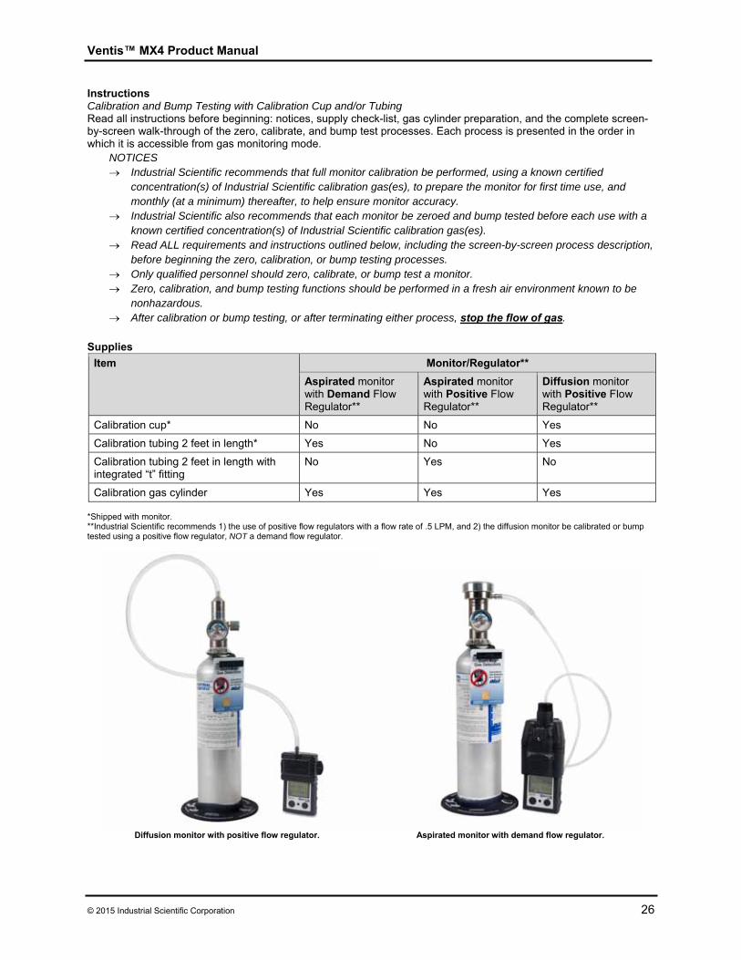
Calibration gas cylinder Yes Yes Yes *Shipped with monitor. **Industrial Scientific recommends 1) the use of positive flow regulators with a flow rate of .5 LPM, and 2) the diffusion monitor be calibrated or bump tested using a positive flow regulator, NOT a demand flow regulator.
Diffusion monitor with positive flow regulator. Aspirated monitor with demand flow regulator.
Ventis™ MX4 Product Manual
27 © 2015 Industrial Scientific Corporation
Prepare the gas cylinder for use According to the supply chart above, attach the correct regulator to the gas cylinder and turn clockwise to tighten. Next, choose instruction A., B., or C. based on the monitor/regulator combination in use.
A. Aspirated with demand flow regulator
Attach either end of the tubing to the cylinder’s nipple. DO NOT ATTACH THE OTHER END OF THE TUBING TO THE MONITOR BEFORE REACHING THE “APPLY GAS SCREEN”. Completing the connection of the tubing will cause gas to flow. If gas is applied before reaching the appropriate screen, the monitor will go into alarm and a failure will be logged.
B. Aspirated with positive flow regulator The calibration tubing with the t-fitting (not included) has two different sized openings, a narrow opening at one end and a wider opening at the other end.
Attach the wider opening to the nipple on the cylinder’s regulator. Attach the smaller opening to the pump inlet.
DO NOT APPLY THE GAS BEFORE REACHING THE “APPLY GAS SCREEN”. If gas is applied before that point, the monitor will go into alarm and a failure will be logged.
C. Diffusion with positive flow regulator Attach either end of the tubing to the cylinder’s nipple. Attach the other end of the tubing to the calibration cup’s nipple.
DO NOT ATTACH THE CALIBRATION CUP TO THE MONITOR OR APPLY THE GAS BEFORE REACHING THE “APPLY GAS SCREEN”. If gas is applied before that point, the monitor will go into alarm and a failure will be logged.
Zero and Quick Calibration Process
Display and Options Instructions
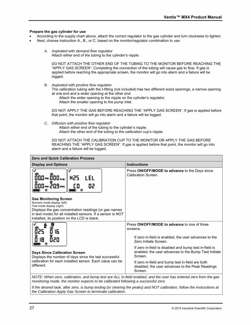
Gas Monitoring Screen Numeric mode display (left) Text mode display (right)
Displays the gas concentration readings (or gas names in text mode) for all installed sensors. If a sensor is NOT installed, its position on the LCD is blank.
Press ON/OFF/MODE to advance to the Days since Calibration Screen.
Days Since Calibration Screen Displays the number of days since the last successful calibration for each installed sensor. Each value can be different.
Press ON/OFF/MODE to advance to one of three screens.
If zero in-field is enabled, the user advances to the Zero Initiate Screen.
If zero in-field is disabled and bump test in-field is enabled, the user advances to the Bump Test Initiate Screen.
If zero in-field and bump test in-field are both disabled, the user advances to the Peak Readings Screen.
NOTE: When zero, calibration, and bump test are ALL in-field enabled, and the user has entered zero from the gas monitoring mode, the monitor expects to be calibrated following a successful zero.
If the desired task, after zero, is bump testing (or clearing the peaks) and NOT calibration, follow the instructions at the Calibration Apply Gas Screen to terminate calibration.
Ventis™ MX4 Product Manual
© 2015 Industrial Scientific Corporation 28
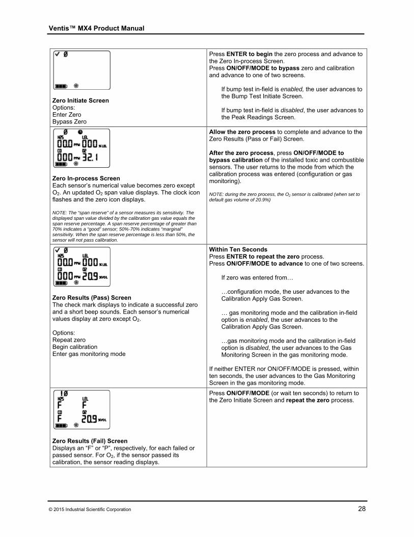
Zero Initiate Screen Options: Enter Zero Bypass Zero
Press ENTER to begin the zero process and advance to the Zero In-process Screen. Press ON/OFF/MODE to bypass zero and calibration and advance to one of two screens.
If bump test in-field is enabled, the user advances to the Bump Test Initiate Screen.
If bump test in-field is disabled, the user advances to the Peak Readings Screen.
Zero In-process Screen Each sensor’s numerical value becomes zero except O2. An updated O2 span value displays. The clock icon flashes and the zero icon displays. NOTE: The “span reserve” of a sensor measures its sensitivity. The displayed span value divided by the calibration gas value equals the span reserve percentage. A span reserve percentage of greater than 70% indicates a “good” sensor; 50%-70% indicates “marginal” sensitivity. When the span reserve percentage is less than 50%, the sensor will not pass calibration.
Allow the zero process to complete and advance to the Zero Results (Pass or Fail) Screen. After the zero process, press ON/OFF/MODE to bypass calibration of the installed toxic and combustible sensors. The user returns to the mode from which the calibration process was entered (configuration or gas monitoring). NOTE: during the zero process, the O2 sensor is calibrated (when set to default gas volume of 20.9%)
Zero Results (Pass) Screen The check mark displays to indicate a successful zero and a short beep sounds. Each sensor’s numerical values display at zero except O2. Options: Repeat zero Begin calibration Enter gas monitoring mode
Within Ten SecondsPress ENTER to repeat the zero process. Press ON/OFF/MODE to advance to one of two screens.
If zero was entered from… …configuration mode, the user advances to the Calibration Apply Gas Screen. … gas monitoring mode and the calibration in-field option is enabled, the user advances to the Calibration Apply Gas Screen.
…gas monitoring mode and the calibration in-field option is disabled, the user advances to the Gas Monitoring Screen in the gas monitoring mode.
If neither ENTER nor ON/OFF/MODE is pressed, within ten seconds, the user advances to the Gas Monitoring Screen in the gas monitoring mode.
Zero Results (Fail) Screen Displays an “F” or “P”, respectively, for each failed or passed sensor. For O2, if the sensor passed its calibration, the sensor reading displays.
Press ON/OFF/MODE (or wait ten seconds) to return to the Zero Initiate Screen and repeat the zero process.
Ventis™ MX4 Product Manual
29 © 2015 Industrial Scientific Corporation
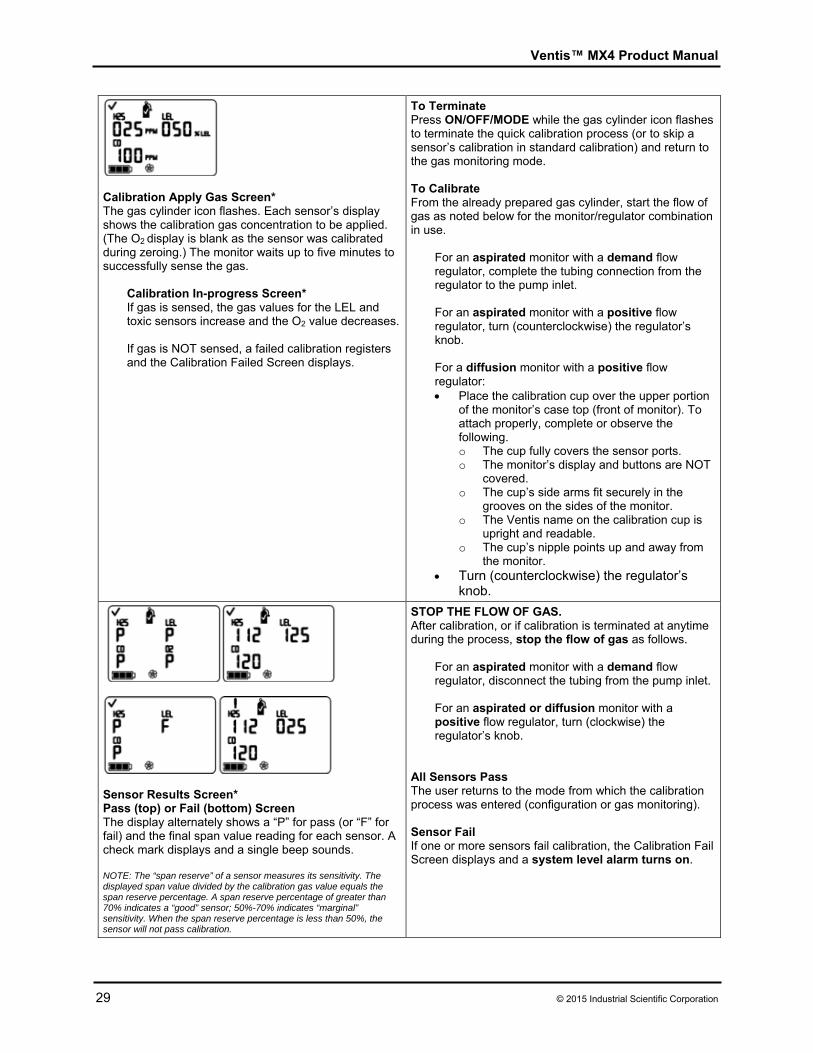
Calibration Apply Gas Screen* The gas cylinder icon flashes. Each sensor’s display shows the calibration gas concentration to be applied. (The O2 display is blank as the sensor was calibrated during zeroing.) The monitor waits up to five minutes to successfully sense the gas.
Calibration In-progress Screen* If gas is sensed, the gas values for the LEL and toxic sensors increase and the O2 value decreases. If gas is NOT sensed, a failed calibration registers and the Calibration Failed Screen displays.
To Terminate Press ON/OFF/MODE while the gas cylinder icon flashes to terminate the quick calibration process (or to skip a sensor’s calibration in standard calibration) and return to the gas monitoring mode. To Calibrate From the already prepared gas cylinder, start the flow of gas as noted below for the monitor/regulator combination in use.
For an aspirated monitor with a demand flow regulator, complete the tubing connection from the regulator to the pump inlet. For an aspirated monitor with a positive flow regulator, turn (counterclockwise) the regulator’s knob. For a diffusion monitor with a positive flow regulator: Place the calibration cup over the upper portion
of the monitor’s case top (front of monitor). To attach properly, complete or observe the following. o The cup fully covers the sensor ports. o The monitor’s display and buttons are NOT
covered. o The cup’s side arms fit securely in the
grooves on the sides of the monitor. o The Ventis name on the calibration cup is
upright and readable. o The cup’s nipple points up and away from
the monitor. Turn (counterclockwise) the regulator’s
knob.
Sensor Results Screen* Pass (top) or Fail (bottom) Screen The display alternately shows a “P” for pass (or “F” for fail) and the final span value reading for each sensor. A check mark displays and a single beep sounds. NOTE: The “span reserve” of a sensor measures its sensitivity. The displayed span value divided by the calibration gas value equals the span reserve percentage. A span reserve percentage of greater than 70% indicates a “good” sensor; 50%-70% indicates “marginal” sensitivity. When the span reserve percentage is less than 50%, the sensor will not pass calibration.
STOP THE FLOW OF GAS. After calibration, or if calibration is terminated at anytime during the process, stop the flow of gas as follows.
For an aspirated monitor with a demand flow regulator, disconnect the tubing from the pump inlet. For an aspirated or diffusion monitor with a positive flow regulator, turn (clockwise) the regulator’s knob.
All Sensors Pass The user returns to the mode from which the calibration process was entered (configuration or gas monitoring).
Sensor Fail If one or more sensors fail calibration, the Calibration Fail Screen displays and a system level alarm turns on.
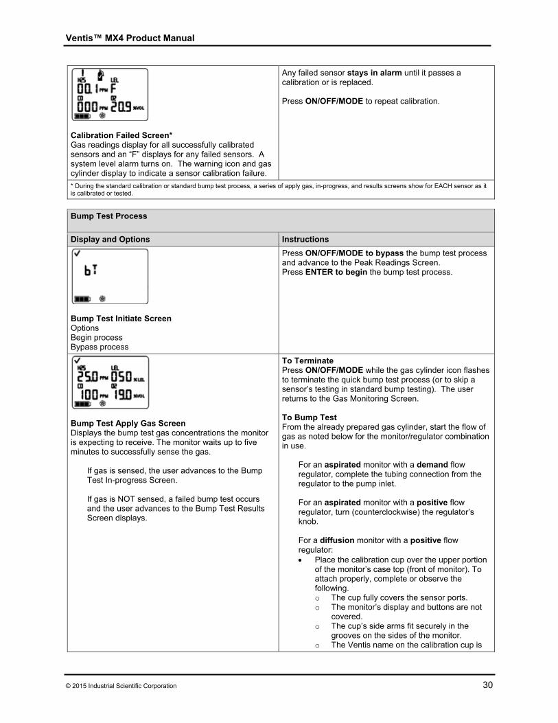
Ventis™ MX4 Product Manual
© 2015 Industrial Scientific Corporation 30
Calibration Failed Screen* Gas readings display for all successfully calibrated sensors and an “F” displays for any failed sensors. A system level alarm turns on. The warning icon and gas cylinder display to indicate a sensor calibration failure.
Any failed sensor stays in alarm until it passes a calibration or is replaced. Press ON/OFF/MODE to repeat calibration.
* During the standard calibration or standard bump test process, a series of apply gas, in-progress, and results screens show for EACH sensor as it is calibrated or tested.
Bump Test Process
Display and Options Instructions
Bump Test Initiate Screen Options Begin process Bypass process
Press ON/OFF/MODE to bypass the bump test process and advance to the Peak Readings Screen. Press ENTER to begin the bump test process.
Bump Test Apply Gas Screen Displays the bump test gas concentrations the monitor is expecting to receive. The monitor waits up to five minutes to successfully sense the gas.
If gas is sensed, the user advances to the Bump Test In-progress Screen. If gas is NOT sensed, a failed bump test occurs and the user advances to the Bump Test Results Screen displays.
To Terminate Press ON/OFF/MODE while the gas cylinder icon flashes to terminate the quick bump test process (or to skip a sensor’s testing in standard bump testing). The user returns to the Gas Monitoring Screen. To Bump Test From the already prepared gas cylinder, start the flow of gas as noted below for the monitor/regulator combination in use.
For an aspirated monitor with a demand flow regulator, complete the tubing connection from the regulator to the pump inlet. For an aspirated monitor with a positive flow regulator, turn (counterclockwise) the regulator’s knob. For a diffusion monitor with a positive flow regulator: Place the calibration cup over the upper portion
of the monitor’s case top (front of monitor). To attach properly, complete or observe the following. o The cup fully covers the sensor ports. o The monitor’s display and buttons are not
covered. o The cup’s side arms fit securely in the
grooves on the sides of the monitor. o The Ventis name on the calibration cup is
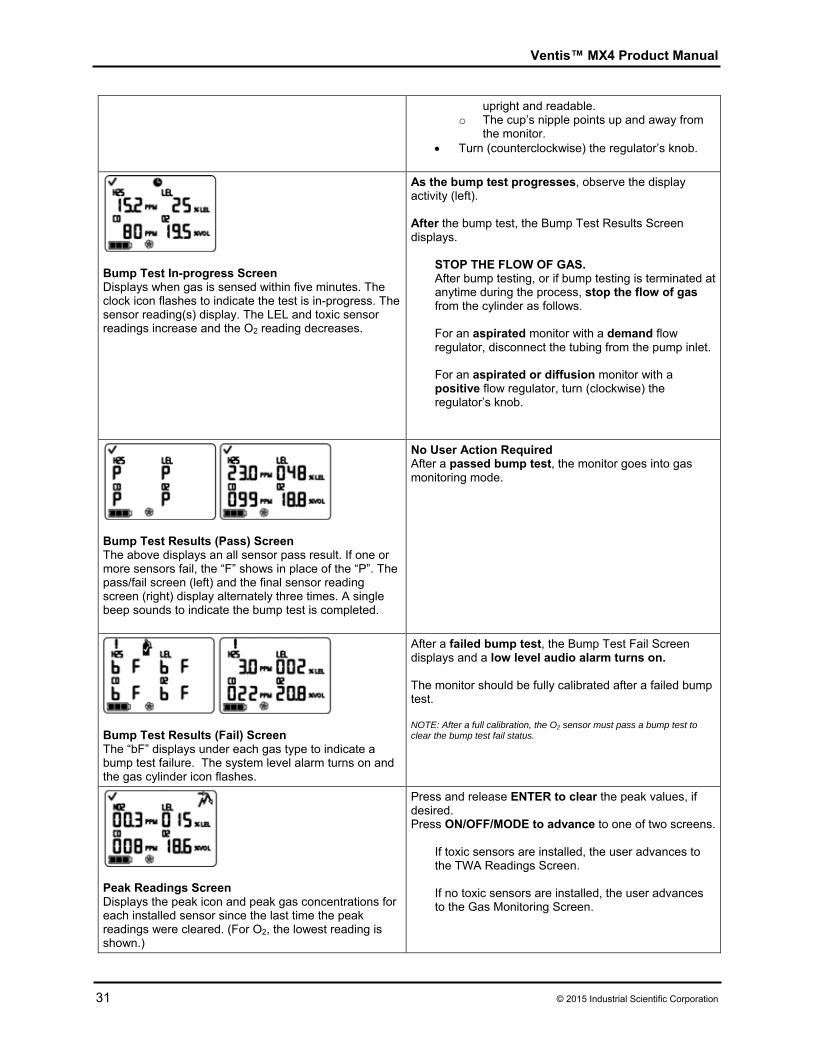
Ventis™ MX4 Product Manual
31 © 2015 Industrial Scientific Corporation
upright and readable. o The cup’s nipple points up and away from
the monitor. Turn (counterclockwise) the regulator’s knob.
Bump Test In-progress Screen Displays when gas is sensed within five minutes. The clock icon flashes to indicate the test is in-progress. The sensor reading(s) display. The LEL and toxic sensor readings increase and the O2 reading decreases.
As the bump test progresses, observe the display activity (left). After the bump test, the Bump Test Results Screen displays.
STOP THE FLOW OF GAS. After bump testing, or if bump testing is terminated at anytime during the process, stop the flow of gas from the cylinder as follows.
For an aspirated monitor with a demand flow regulator, disconnect the tubing from the pump inlet. For an aspirated or diffusion monitor with a positive flow regulator, turn (clockwise) the regulator’s knob.
Bump Test Results (Pass) Screen The above displays an all sensor pass result. If one or more sensors fail, the “F” shows in place of the “P”. The pass/fail screen (left) and the final sensor reading screen (right) display alternately three times. A single beep sounds to indicate the bump test is completed.
No User Action Required After a passed bump test, the monitor goes into gas monitoring mode.
Bump Test Results (Fail) Screen The “bF” displays under each gas type to indicate a bump test failure. The system level alarm turns on and the gas cylinder icon flashes.
After a failed bump test, the Bump Test Fail Screen displays and a low level audio alarm turns on. The monitor should be fully calibrated after a failed bump test. NOTE: After a full calibration, the O2 sensor must pass a bump test to clear the bump test fail status.
Peak Readings Screen Displays the peak icon and peak gas concentrations for each installed sensor since the last time the peak readings were cleared. (For O2, the lowest reading is shown.)
Press and release ENTER to clear the peak values, if desired. Press ON/OFF/MODE to advance to one of two screens.
If toxic sensors are installed, the user advances to the TWA Readings Screen. If no toxic sensors are installed, the user advances to the Gas Monitoring Screen.
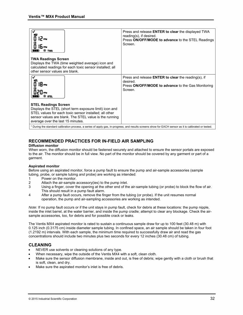
Ventis™ MX4 Product Manual
© 2015 Industrial Scientific Corporation 32
TWA Readings Screen Displays the TWA (time weighted average) icon and calculated readings for each toxic sensor installed; all other sensor values are blank.
Press and release ENTER to clear the displayed TWA reading(s), if desired. Press ON/OFF/MODE to advance to the STEL Readings Screen.
STEL Readings Screen Displays the STEL (short term exposure limit) icon and STEL values for each toxic sensor installed; all other sensor values are blank. The STEL value is the running average over the last 15 minutes.
Press and release ENTER to clear the reading(s), if desired. Press ON/OFF/MODE to advance to the Gas Monitoring Screen.
* During the standard calibration process, a series of apply gas, in-progress, and results screens show for EACH sensor as it is calibrated or tested.
RECOMMENDED PRACTICES FOR IN-FIELD AIR SAMPLING Diffusion monitor When worn, the diffusion monitor should be fastened securely and attached to ensure the sensor portals are exposed to the air. The monitor should be in full view. No part of the monitor should be covered by any garment or part of a garment. Aspirated monitor Before using an aspirated monitor, force a pump fault to ensure the pump and air-sample accessories (sample tubing, probe, or sample tubing and probe) are working as intended: 1 Power on the monitor. 2 Attach the air-sample accessory(ies) to the pump inlet. 3 Using a finger, cover the opening at the other end of the air-sample tubing (or probe) to block the flow of air.
This should result in a pump fault alarm. 4 After a pump fault occurs, remove the finger from the tubing (or probe). If the unit resumes normal
operation, the pump and air-sampling accessories are working as intended.
Note: If no pump fault occurs or if the unit stays in pump fault, check for debris at these locations: the pump nipple, inside the inlet barrel, at the water barrier, and inside the pump cradle; attempt to clear any blockage. Check the air-sample accessories, too, for debris and for possible crack or leaks. The Ventis MX4 aspirated monitor is rated to sustain a continuous sample draw for up to 100 feet (30.48 m) with 0.125 inch (0.3175 cm) inside diameter sample tubing. In confined space, an air sample should be taken in four foot (1.2192 m) intervals. With each sample, the minimum time required to successfully draw air and read the gas concentrations should include two minutes plus two seconds for every 12 inches (30.48 cm) of tubing. CLEANING NEVER use solvents or cleaning solutions of any type. When necessary, wipe the outside of the Ventis MX4 with a soft, clean cloth. Make sure the sensor diffusion membrane, inside and out, is free of debris; wipe gently with a cloth or brush that
is soft, clean, and dry. Make sure the aspirated monitor’s inlet is free of debris.
Ventis™ MX4 Product Manual
33 © 2015 Industrial Scientific Corporation
SERVICE Instructions are provided for battery service; monitor conversion (diffusion to aspirated and vice versa); sensor, sensor barrier and LCD service; and pump assembly service. Refer to the three-dimensional view diagrams to identify the parts referenced in the instruction sets, and for screw torque values. Read all instructions before beginning any monitor service.
NOTICES Before beginning any service tasks, power-off the monitor. Only qualified staff should perform monitor service and should take the following precautions.
Take care not to touch battery contacts on the monitor or the battery itself. Perform work in a clean air environment that is known to be nonhazardous. Perform work on a nonconductive work surface. Wear grounding straps.
BATTERY PACKS
NOTICES WARNING: INSERT THE ALKALINE BATTERIES WITH THE CORRECT POSITIVE “ + ” AND NEGATIVE
“-“ ORIENTATION. FAILURE TO FOLLOW PROPER BATTERY ORIENTATION WILL RESULT IN DAMAGE TO THE MONITOR.
WARNING: The Ventis MX4 is only approved for use with AAA battery types Energizer EN92 and Duracell MN2400. Do NOT mix battery types.
Battery service instruction sets are provided below for each allowable monitor/battery pack combination. Please choose, read, and then follow the appropriate instruction set.
Aspirated Monitor Battery Replacement For an aspirated monitor, two of the three Ventis battery packs can be used. The Extended Range Li-ion battery is replaced as a single part. The Alkaline battery unit consists of batteries and a pack for the batteries.
ASPIRATED MONITOR BATTERY REPLACEMENT.
Removing the Battery Pack.
1 Power-off the monitor.
2 Loosen the four captive screws on the lower portion of the pump module bottom (back of the module).
3 Loosen the single captive screw on the pump door.
4 Slide the pump door down; lift to reveal and access the monitor.
5 Lift and remove the monitor from the pump module; set aside the monitor.
6 Lift and remove the battery pack from inside the lower portion of the pump module.
Replacing the Battery Pack. If inserting the Alkaline battery pack, follow steps 1-5. If inserting the Extended Range Li-ion battery pack, follow step 5 ONLY.
1 To prepare the alkaline battery pack, unlatch and lift the hinged portion of the battery pack.
2 If needed, remove and set aside the spent batteries from within the pack.
3 Insert new batteries so that their negative contacts are in contact with the springs inside the pack. DO NOT MIX BATTERY TYPES.
4 Close the latch. A click sounds.
5 To properly place the Extended Range Li-ion (or Alkaline) battery pack inside the pump module, complete or observe the following: the battery circuitry is exposed and faces the user; a small groove at the back of the battery bottom fits over the small rib at the back of the pump
module bottom.
Ventis™ MX4 Product Manual
© 2015 Industrial Scientific Corporation 34
Reassembling the Aspirated Monitor.
1 Re-place the monitor inside the pump module. The monitor is display side up and its logo readable. Its lower exposed bottom portion covers the battery.
2 Tighten the four screws on the pump module bottom to secure the module to the monitor.
3 Lower and close the pump door; slide up to click in place.
4 Tighten the pump door screw to secure the door in place.
5 Dispose of any spent batteries according to company policy.
Diffusion Monitor Battery Replacement or Changeover The diffusion monitor can be used with all three Ventis battery packs. The Li-ion battery kit is a single part consisting of the monitor’s lower case bottom and the battery. It is
removed from and attached to the diffusion monitor as a single item. The Extended Range Li-ion battery pack and its cover are two distinct items. The Alkaline battery pack consists of three items: the batteries, the battery pack, and a battery pack cover
(the same cover that holds the Extended Range Li-ion battery).
NOTE: When an Extended Range Li-ion (or Alkaline) battery pack is attached to a diffusion monitor, the monitor’s lower portion becomes deeper than its upper portion. The Conversion Kit’s suspender clip components are used to make the upper and lower portions depth-compatible. The Conversion Kit provides a battery cover (battery not included), a suspender clip and spacer, and a screw and washer.
ATTACHING THE LI-ION BATTERY TO A DIFFUSION MONITOR.
Battery Replacement.
1 Power-off the monitor.
2 Loosen the four captive screws on the lower portion of the case bottom (or the battery cover if the Extended Range Li-ion or Alkaline battery pack is attached).
3 Lift and remove the Li-ion kit (or Extended Range Li-ion battery Alkaline battery pack and cover); set aside.
4 To properly attach the new Li-ion battery kit to the monitor, align its exterior charging contacts with the monitor’s bottom.
5 Tighten the four captive screws to secure the battery pack to the monitor.
6 Dispose of any spent batteries according to company policy, or properly store any battery packs that have a remaining life.
To changeover from an Extended Range Li-ion (or Alkaline) battery pack to a Li-ion battery continue with the following suspender clip instruction sets.
Removal of the Suspender Clip and Spacer.
1 On the monitor’s case bottom, open the suspender clip.
2 Using a Phillips head screwdriver, remove the screw and washer that attach the suspender clip and spacer to the monitor.
3 Set aside and store the removed items for future use with the Extended Range Li-ion (or Alkaline) battery pack on a diffusion monitor.
Attachment of the Suspender Clip.
1 Open the suspender clip.
2 Place the washer on the screw (P/N 17139262).
3 Insert the screw with washer through the clip’s center hole and into the screw hole on the monitor.
4 Tighten the screw to secure the suspender clip to the monitor.
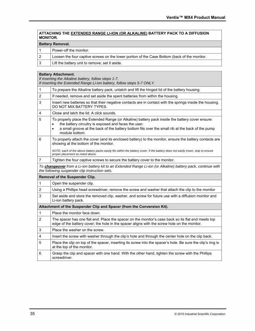
Ventis™ MX4 Product Manual
35 © 2015 Industrial Scientific Corporation
ATTACHING THE EXTENDED RANGE LI-ION (OR ALKALINE) BATTERY PACK TO A DIFFUSION MONITOR.
Battery Removal.
1 Power-off the monitor.
2 Loosen the four captive screws on the lower portion of the Case Bottom (back of the monitor.
3 Lift the battery unit to remove; set it aside.
Battery Attachment. If inserting the Alkaline battery, follow steps 1-7. If inserting the Extended Range Li-ion battery, follow steps 5-7 ONLY.
1 To prepare the Alkaline battery pack, unlatch and lift the hinged lid of the battery housing.
2 If needed, remove and set aside the spent batteries from within the housing.
3 Insert new batteries so that their negative contacts are in contact with the springs inside the housing. DO NOT MIX BATTERY TYPES.
4 Close and latch the lid. A click sounds.
5 To properly place the Extended Range (or Alkaline) battery pack inside the battery cover ensure: the battery circuitry is exposed and faces the user; a small groove at the back of the battery bottom fits over the small rib at the back of the pump
module bottom.
6 To properly attach the cover (and its enclosed battery) to the monitor, ensure the battery contacts are showing at the bottom of the monitor. NOTE: each of the above battery packs easily fits within the battery cover. If the battery does not easily insert, stop to ensure proper placement as noted above.
7 Tighten the four captive screws to secure the battery cover to the monitor.
To changeover from a Li-ion battery kit to an Extended Range Li-ion (or Alkaline) battery pack, continue with the following suspender clip instruction sets.
Removal of the Suspender Clip.
1 Open the suspender clip.
2 Using a Phillips head screwdriver, remove the screw and washer that attach the clip to the monitor
3 Set aside and store the removed clip, washer, and screw for future use with a diffusion monitor and Li-ion battery pack.
Attachment of the Suspender Clip and Spacer (from the Conversion Kit).
1 Place the monitor face down.
2 The spacer has one flat end. Place the spacer on the monitor’s case back so its flat end meets top edge of the battery cover; the hole in the spacer aligns with the screw hole on the monitor.
3 Place the washer on the screw.
4 Insert the screw with washer through the clip’s hole and through the center hole on the clip back.
5 Place the clip on top of the spacer, inserting its screw into the spacer’s hole. Be sure the clip’s ring is at the top of the monitor.
6 Grasp the clip and spacer with one hand. With the other hand, tighten the screw with the Phillips screwdriver.
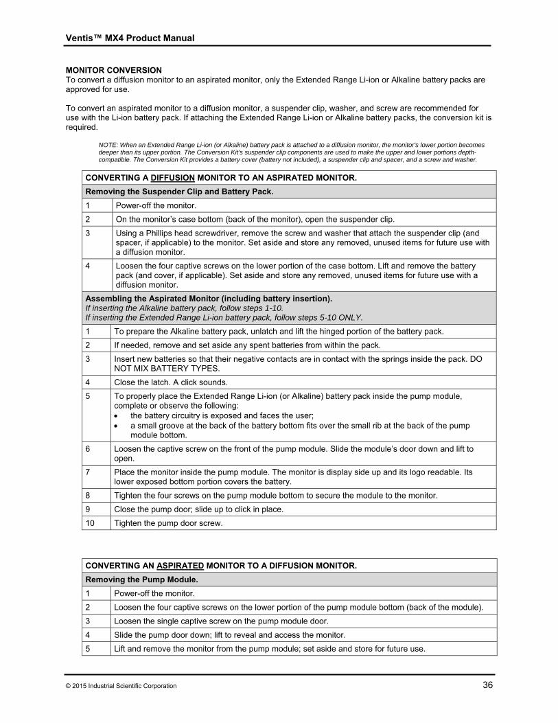
Ventis™ MX4 Product Manual
© 2015 Industrial Scientific Corporation 36
MONITOR CONVERSION To convert a diffusion monitor to an aspirated monitor, only the Extended Range Li-ion or Alkaline battery packs are approved for use.
To convert an aspirated monitor to a diffusion monitor, a suspender clip, washer, and screw are recommended for use with the Li-ion battery pack. If attaching the Extended Range Li-ion or Alkaline battery packs, the conversion kit is required.
NOTE: When an Extended Range Li-ion (or Alkaline) battery pack is attached to a diffusion monitor, the monitor’s lower portion becomes deeper than its upper portion. The Conversion Kit’s suspender clip components are used to make the upper and lower portions depth-compatible. The Conversion Kit provides a battery cover (battery not included), a suspender clip and spacer, and a screw and washer.
CONVERTING A DIFFUSION MONITOR TO AN ASPIRATED MONITOR.
Removing the Suspender Clip and Battery Pack.
1 Power-off the monitor.
2 On the monitor’s case bottom (back of the monitor), open the suspender clip.
3 Using a Phillips head screwdriver, remove the screw and washer that attach the suspender clip (and spacer, if applicable) to the monitor. Set aside and store any removed, unused items for future use with a diffusion monitor.
4 Loosen the four captive screws on the lower portion of the case bottom. Lift and remove the battery pack (and cover, if applicable). Set aside and store any removed, unused items for future use with a diffusion monitor.
Assembling the Aspirated Monitor (including battery insertion). If inserting the Alkaline battery pack, follow steps 1-10. If inserting the Extended Range Li-ion battery pack, follow steps 5-10 ONLY.
1 To prepare the Alkaline battery pack, unlatch and lift the hinged portion of the battery pack.
2 If needed, remove and set aside any spent batteries from within the pack.
3 Insert new batteries so that their negative contacts are in contact with the springs inside the pack. DO NOT MIX BATTERY TYPES.
4 Close the latch. A click sounds.
5 To properly place the Extended Range Li-ion (or Alkaline) battery pack inside the pump module, complete or observe the following: the battery circuitry is exposed and faces the user; a small groove at the back of the battery bottom fits over the small rib at the back of the pump
module bottom.
6 Loosen the captive screw on the front of the pump module. Slide the module’s door down and lift to open.
7 Place the monitor inside the pump module. The monitor is display side up and its logo readable. Its lower exposed bottom portion covers the battery.
8 Tighten the four screws on the pump module bottom to secure the module to the monitor.
9 Close the pump door; slide up to click in place.
10 Tighten the pump door screw.
CONVERTING AN ASPIRATED MONITOR TO A DIFFUSION MONITOR.
Removing the Pump Module.
1 Power-off the monitor.
2 Loosen the four captive screws on the lower portion of the pump module bottom (back of the module).
3 Loosen the single captive screw on the pump module door.
4 Slide the pump door down; lift to reveal and access the monitor.
5 Lift and remove the monitor from the pump module; set aside and store for future use.
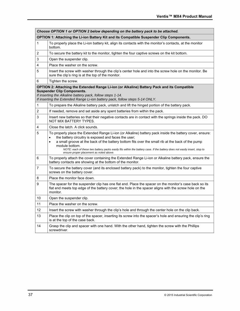
Ventis™ MX4 Product Manual
37 © 2015 Industrial Scientific Corporation
Choose OPTION 1 or OPTION 2 below depending on the battery pack to be attached.
OPTION 1: Attaching the Li-ion Battery Kit and its Compatible Suspender Clip Components.
1 To properly place the Li-ion battery kit, align its contacts with the monitor’s contacts, at the monitor bottom.
2 To secure the battery kit to the monitor, tighten the four captive screws on the kit bottom.
3 Open the suspender clip.
4 Place the washer on the screw.
5 Insert the screw with washer through the clip’s center hole and into the screw hole on the monitor. Be sure the clip’s ring is at the top of the monitor.
6 Tighten the screw.
OPTION 2: Attaching the Extended Range Li-ion (or Alkaline) Battery Pack and its Compatible Suspender Clip Components. If inserting the Alkaline battery pack, follow steps 1-14. If inserting the Extended Range Li-ion battery pack, follow steps 5-14 ONLY.
1 To prepare the Alkaline battery pack, unlatch and lift the hinged portion of the battery pack.
2 If needed, remove and set aside any spent batteries from within the pack.
3 Insert new batteries so that their negative contacts are in contact with the springs inside the pack. DO NOT MIX BATTERY TYPES.
4 Close the latch. A click sounds.
5 To properly place the Extended Range Li-ion (or Alkaline) battery pack inside the battery cover, ensure: the battery circuitry is exposed and faces the user; a small groove at the back of the battery bottom fits over the small rib at the back of the pump
module bottom. NOTE: each of these two battery packs easily fits within the battery case. If the battery does not easily insert, stop to ensure proper placement as noted above.
6 To properly attach the cover containing the Extended Range Li-ion or Alkaline battery pack, ensure the battery contacts are showing at the bottom of the monitor.
7 To secure the battery cover (and its enclosed battery pack) to the monitor, tighten the four captive screws on the battery cover.
8 Place the monitor face down.
9 The spacer for the suspender clip has one flat end. Place the spacer on the monitor’s case back so its flat end meets top edge of the battery cover; the hole in the spacer aligns with the screw hole on the monitor.
10 Open the suspender clip.
11 Place the washer on the screw.
12 Insert the screw with washer through the clip’s hole and through the center hole on the clip back.
13 Place the clip on top of the spacer, inserting its screw into the spacer’s hole and ensuring the clip’s ring is at the top of the case back.
14 Grasp the clip and spacer with one hand. With the other hand, tighten the screw with the Phillips screwdriver.
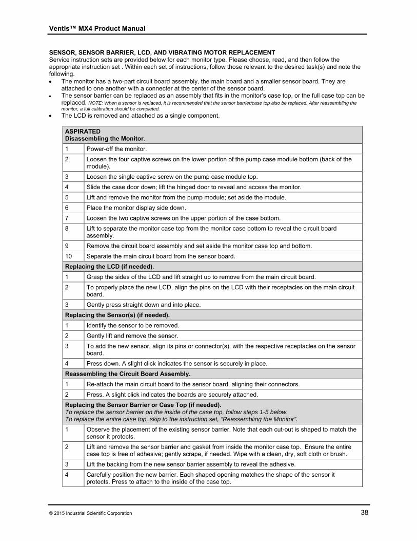
Ventis™ MX4 Product Manual
© 2015 Industrial Scientific Corporation 38
SENSOR, SENSOR BARRIER, LCD, AND VIBRATING MOTOR REPLACEMENT Service instruction sets are provided below for each monitor type. Please choose, read, and then follow the appropriate instruction set . Within each set of instructions, follow those relevant to the desired task(s) and note the following. The monitor has a two-part circuit board assembly, the main board and a smaller sensor board. They are
attached to one another with a connecter at the center of the sensor board. The sensor barrier can be replaced as an assembly that fits in the monitor’s case top, or the full case top can be
replaced. NOTE: When a sensor is replaced, it is recommended that the sensor barrier/case top also be replaced. After reassembling the monitor, a full calibration should be completed.
The LCD is removed and attached as a single component.
ASPIRATED Disassembling the Monitor.
1 Power-off the monitor.
2 Loosen the four captive screws on the lower portion of the pump case module bottom (back of the module).
3 Loosen the single captive screw on the pump case module top.
4 Slide the case door down; lift the hinged door to reveal and access the monitor.
5 Lift and remove the monitor from the pump module; set aside the module.
6 Place the monitor display side down.
7 Loosen the two captive screws on the upper portion of the case bottom.
8 Lift to separate the monitor case top from the monitor case bottom to reveal the circuit board assembly.
9 Remove the circuit board assembly and set aside the monitor case top and bottom.
10 Separate the main circuit board from the sensor board.
Replacing the LCD (if needed).
1 Grasp the sides of the LCD and lift straight up to remove from the main circuit board.
2 To properly place the new LCD, align the pins on the LCD with their receptacles on the main circuit board.
3 Gently press straight down and into place.
Replacing the Sensor(s) (if needed).
1 Identify the sensor to be removed.
2 Gently lift and remove the sensor.
3 To add the new sensor, align its pins or connector(s), with the respective receptacles on the sensor board.
4 Press down. A slight click indicates the sensor is securely in place.
Reassembling the Circuit Board Assembly.
1 Re-attach the main circuit board to the sensor board, aligning their connectors.
2 Press. A slight click indicates the boards are securely attached.
Replacing the Sensor Barrier or Case Top (if needed).To replace the sensor barrier on the inside of the case top, follow steps 1-5 below. To replace the entire case top, skip to the instruction set, “Reassembling the Monitor”.
1 Observe the placement of the existing sensor barrier. Note that each cut-out is shaped to match the sensor it protects.
2 Lift and remove the sensor barrier and gasket from inside the monitor case top. Ensure the entire case top is free of adhesive; gently scrape, if needed. Wipe with a clean, dry, soft cloth or brush.
3 Lift the backing from the new sensor barrier assembly to reveal the adhesive.
4 Carefully position the new barrier. Each shaped opening matches the shape of the sensor it protects. Press to attach to the inside of the case top.
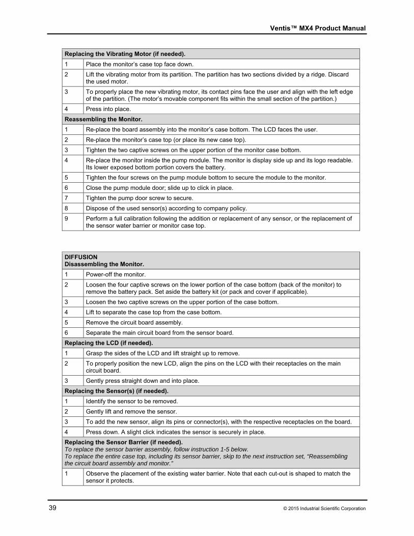
Ventis™ MX4 Product Manual
39 © 2015 Industrial Scientific Corporation
Replacing the Vibrating Motor (if needed).
1 Place the monitor’s case top face down.
2 Lift the vibrating motor from its partition. The partition has two sections divided by a ridge. Discard the used motor.
3 To properly place the new vibrating motor, its contact pins face the user and align with the left edge of the partition. (The motor’s movable component fits within the small section of the partition.)
4 Press into place.
Reassembling the Monitor.
1 Re-place the board assembly into the monitor’s case bottom. The LCD faces the user.
2 Re-place the monitor’s case top (or place its new case top).
3 Tighten the two captive screws on the upper portion of the monitor case bottom.
4 Re-place the monitor inside the pump module. The monitor is display side up and its logo readable. Its lower exposed bottom portion covers the battery.
5 Tighten the four screws on the pump module bottom to secure the module to the monitor.
6 Close the pump module door; slide up to click in place.
7 Tighten the pump door screw to secure.
8 Dispose of the used sensor(s) according to company policy.
9 Perform a full calibration following the addition or replacement of any sensor, or the replacement of the sensor water barrier or monitor case top.
DIFFUSION Disassembling the Monitor.
1 Power-off the monitor.
2 Loosen the four captive screws on the lower portion of the case bottom (back of the monitor) to remove the battery pack. Set aside the battery kit (or pack and cover if applicable).
3 Loosen the two captive screws on the upper portion of the case bottom.
4 Lift to separate the case top from the case bottom.
5 Remove the circuit board assembly.
6 Separate the main circuit board from the sensor board.
Replacing the LCD (if needed).
1 Grasp the sides of the LCD and lift straight up to remove.
2 To properly position the new LCD, align the pins on the LCD with their receptacles on the main circuit board.
3 Gently press straight down and into place.
Replacing the Sensor(s) (if needed).
1 Identify the sensor to be removed.
2 Gently lift and remove the sensor.
3 To add the new sensor, align its pins or connector(s), with the respective receptacles on the board.
4 Press down. A slight click indicates the sensor is securely in place.
Replacing the Sensor Barrier (if needed).To replace the sensor barrier assembly, follow instruction 1-5 below. To replace the entire case top, including its sensor barrier, skip to the next instruction set, “Reassembling the circuit board assembly and monitor.”
1 Observe the placement of the existing water barrier. Note that each cut-out is shaped to match the sensor it protects.
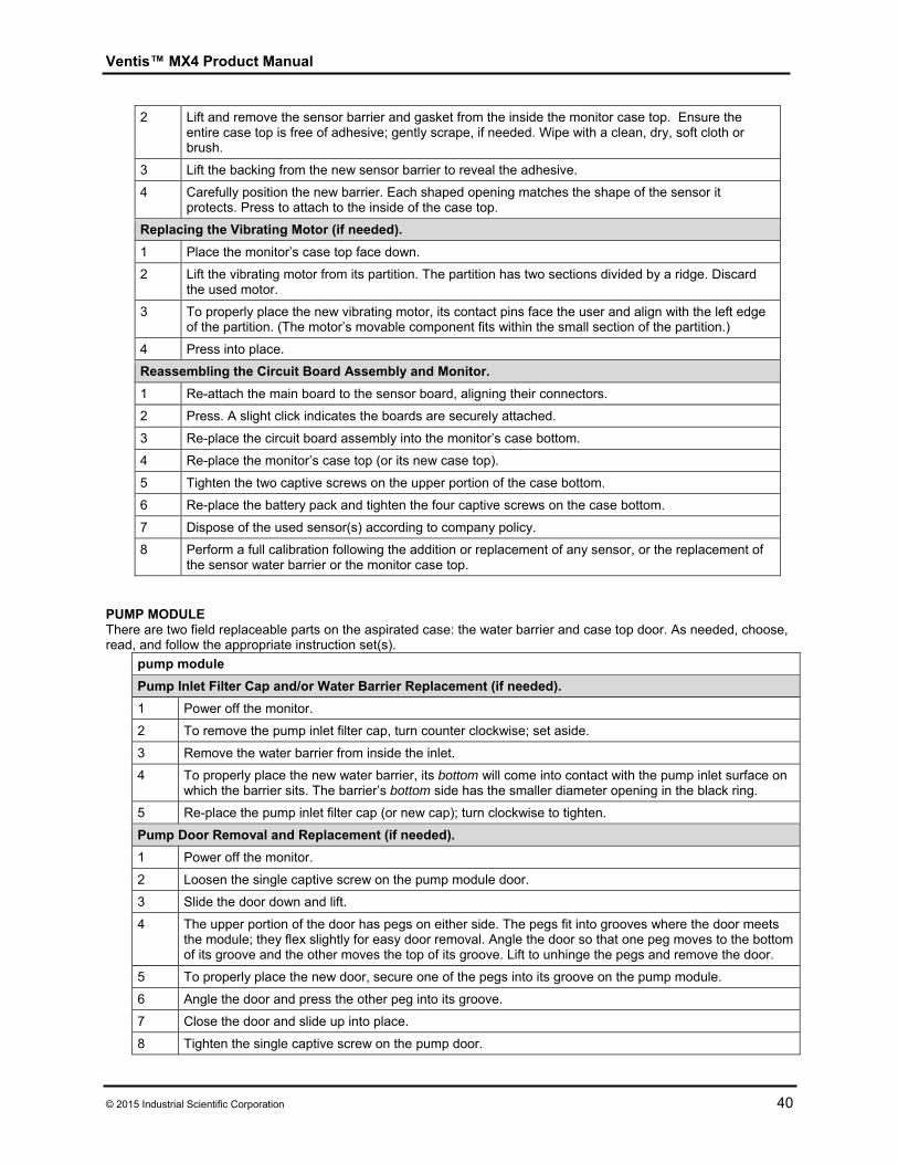
Ventis™ MX4 Product Manual
© 2015 Industrial Scientific Corporation 40
2 Lift and remove the sensor barrier and gasket from the inside the monitor case top. Ensure the entire case top is free of adhesive; gently scrape, if needed. Wipe with a clean, dry, soft cloth or brush.
3 Lift the backing from the new sensor barrier to reveal the adhesive.
4 Carefully position the new barrier. Each shaped opening matches the shape of the sensor it protects. Press to attach to the inside of the case top.
Replacing the Vibrating Motor (if needed).
1 Place the monitor’s case top face down.
2 Lift the vibrating motor from its partition. The partition has two sections divided by a ridge. Discard the used motor.
3 To properly place the new vibrating motor, its contact pins face the user and align with the left edge of the partition. (The motor’s movable component fits within the small section of the partition.)
4 Press into place.
Reassembling the Circuit Board Assembly and Monitor.
1 Re-attach the main board to the sensor board, aligning their connectors.
2 Press. A slight click indicates the boards are securely attached.
3 Re-place the circuit board assembly into the monitor’s case bottom.
4 Re-place the monitor’s case top (or its new case top).
5 Tighten the two captive screws on the upper portion of the case bottom.
6 Re-place the battery pack and tighten the four captive screws on the case bottom.
7 Dispose of the used sensor(s) according to company policy.
8 Perform a full calibration following the addition or replacement of any sensor, or the replacement of the sensor water barrier or the monitor case top.
PUMP MODULE There are two field replaceable parts on the aspirated case: the water barrier and case top door. As needed, choose, read, and follow the appropriate instruction set(s).
pump module
Pump Inlet Filter Cap and/or Water Barrier Replacement (if needed).
1 Power off the monitor.
2 To remove the pump inlet filter cap, turn counter clockwise; set aside.
3 Remove the water barrier from inside the inlet.
4 To properly place the new water barrier, its bottom will come into contact with the pump inlet surface on which the barrier sits. The barrier’s bottom side has the smaller diameter opening in the black ring.
5 Re-place the pump inlet filter cap (or new cap); turn clockwise to tighten.
Pump Door Removal and Replacement (if needed).
1 Power off the monitor.
2 Loosen the single captive screw on the pump module door.
3 Slide the door down and lift.
4 The upper portion of the door has pegs on either side. The pegs fit into grooves where the door meets the module; they flex slightly for easy door removal. Angle the door so that one peg moves to the bottom of its groove and the other moves the top of its groove. Lift to unhinge the pegs and remove the door.
5 To properly place the new door, secure one of the pegs into its groove on the pump module.
6 Angle the door and press the other peg into its groove.
7 Close the door and slide up into place.
8 Tighten the single captive screw on the pump door.
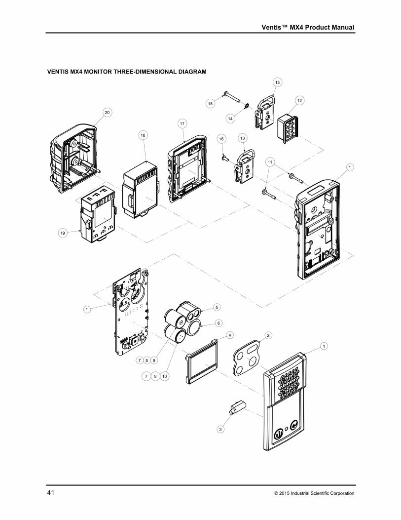
Ventis™ MX4 Product Manual
41 © 2015 Industrial Scientific Corporation
VENTIS MX4 MONITOR THREE-DIMENSIONAL DIAGRAM
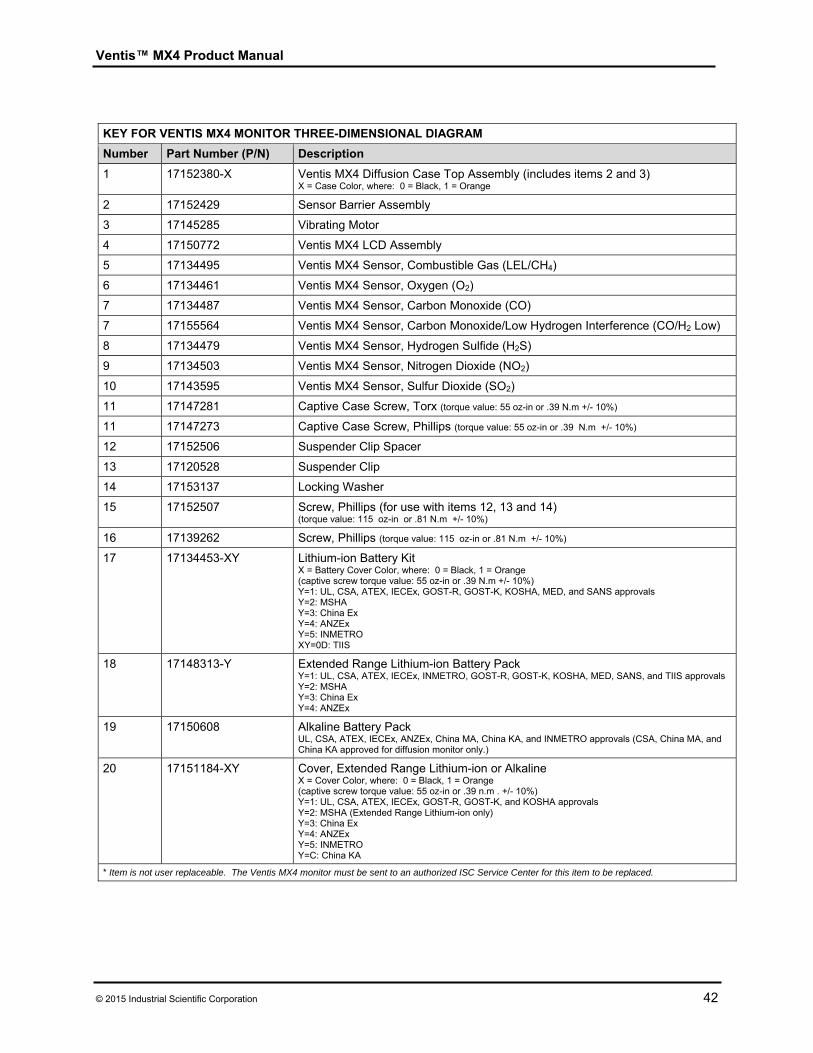
Ventis™ MX4 Product Manual
© 2015 Industrial Scientific Corporation 42
KEY FOR VENTIS MX4 MONITOR THREE-DIMENSIONAL DIAGRAM
Number Part Number (P/N) Description
1 17152380-X Ventis MX4 Diffusion Case Top Assembly (includes items 2 and 3) X = Case Color, where: 0 = Black, 1 = Orange
2 17152429 Sensor Barrier Assembly
3 17145285 Vibrating Motor
4 17150772 Ventis MX4 LCD Assembly
5 17134495 Ventis MX4 Sensor, Combustible Gas (LEL/CH4)
6 17134461 Ventis MX4 Sensor, Oxygen (O2)
7 17134487 Ventis MX4 Sensor, Carbon Monoxide (CO)
7 17155564 Ventis MX4 Sensor, Carbon Monoxide/Low Hydrogen Interference (CO/H2 Low)
8 17134479 Ventis MX4 Sensor, Hydrogen Sulfide (H2S)
9 17134503 Ventis MX4 Sensor, Nitrogen Dioxide (NO2)
10 17143595 Ventis MX4 Sensor, Sulfur Dioxide (SO2)
11 17147281 Captive Case Screw, Torx (torque value: 55 oz-in or .39 N.m +/- 10%)
11 17147273 Captive Case Screw, Phillips (torque value: 55 oz-in or .39 N.m +/- 10%)
12 17152506 Suspender Clip Spacer
13 17120528 Suspender Clip
14 17153137 Locking Washer
15 17152507 Screw, Phillips (for use with items 12, 13 and 14) (torque value: 115 oz-in or .81 N.m +/- 10%)
16 17139262 Screw, Phillips (torque value: 115 oz-in or .81 N.m +/- 10%)
17 17134453-XY Lithium-ion Battery Kit X = Battery Cover Color, where: 0 = Black, 1 = Orange (captive screw torque value: 55 oz-in or .39 N.m +/- 10%) Y=1: UL, CSA, ATEX, IECEx, GOST-R, GOST-K, KOSHA, MED, and SANS approvals Y=2: MSHA Y=3: China Ex Y=4: ANZEx Y=5: INMETRO XY=0D: TIIS
18 17148313-Y Extended Range Lithium-ion Battery Pack Y=1: UL, CSA, ATEX, IECEx, INMETRO, GOST-R, GOST-K, KOSHA, MED, SANS, and TIIS approvals Y=2: MSHA Y=3: China Ex Y=4: ANZEx
19 17150608 Alkaline Battery Pack UL, CSA, ATEX, IECEx, ANZEx, China MA, China KA, and INMETRO approvals (CSA, China MA, and China KA approved for diffusion monitor only.)
20 17151184-XY Cover, Extended Range Lithium-ion or Alkaline X = Cover Color, where: 0 = Black, 1 = Orange (captive screw torque value: 55 oz-in or .39 n.m . +/- 10%) Y=1: UL, CSA, ATEX, IECEx, GOST-R, GOST-K, and KOSHA approvals Y=2: MSHA (Extended Range Lithium-ion only) Y=3: China Ex Y=4: ANZEx Y=5: INMETRO Y=C: China KA
* Item is not user replaceable. The Ventis MX4 monitor must be sent to an authorized ISC Service Center for this item to be replaced.
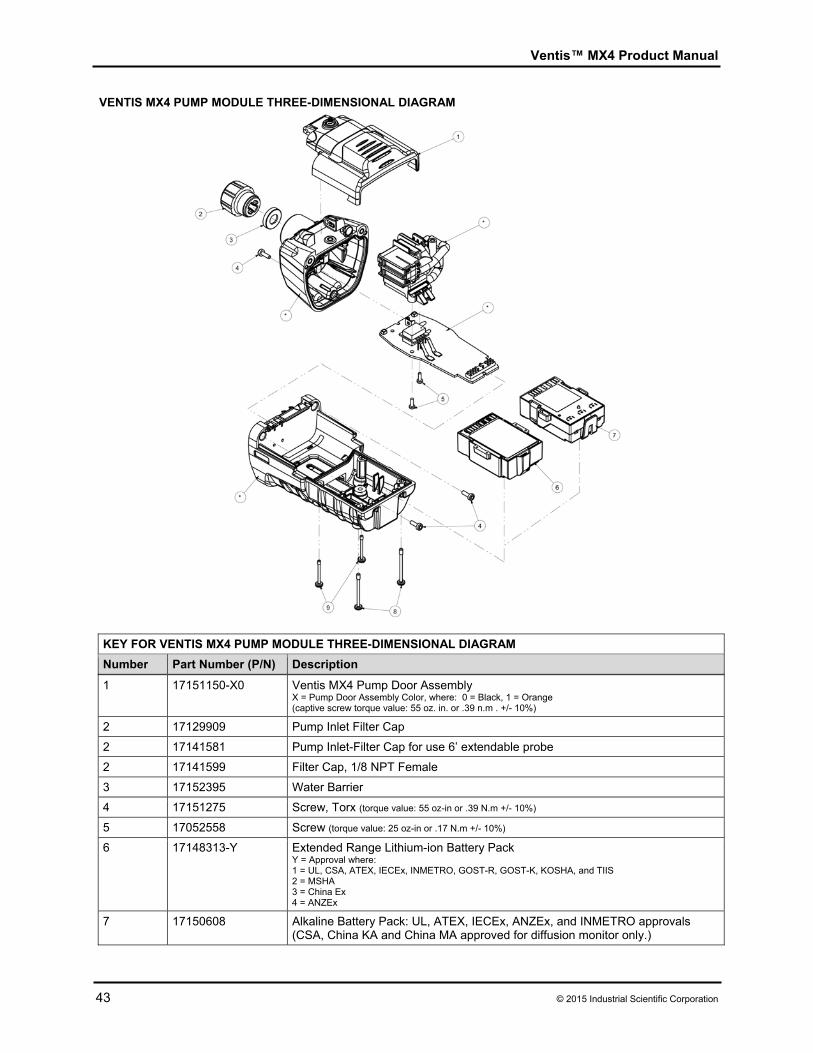
Ventis™ MX4 Product Manual
43 © 2015 Industrial Scientific Corporation
VENTIS MX4 PUMP MODULE THREE-DIMENSIONAL DIAGRAM
1 17151150-X0 Ventis MX4 Pump Door Assembly X = Pump Door Assembly Color, where: 0 = Black, 1 = Orange (captive screw torque value: 55 oz. in. or .39 n.m . +/- 10%)
2 17129909 Pump Inlet Filter Cap
2 17141581 Pump Inlet-Filter Cap for use 6’ extendable probe
2 17141599 Filter Cap, 1/8 NPT Female
3 17152395 Water Barrier
4 17151275 Screw, Torx (torque value: 55 oz-in or .39 N.m +/- 10%)
5 17052558 Screw (torque value: 25 oz-in or .17 N.m +/- 10%)
6 17148313-Y Extended Range Lithium-ion Battery Pack Y = Approval where: 1 = UL, CSA, ATEX, IECEx, INMETRO, GOST-R, GOST-K, KOSHA, and TIIS 2 = MSHA 3 = China Ex 4 = ANZEx
7 17150608 Alkaline Battery Pack: UL, ATEX, IECEx, ANZEx, and INMETRO approvals (CSA, China KA and China MA approved for diffusion monitor only.)
KEY FOR VENTIS MX4 PUMP MODULE THREE-DIMENSIONAL DIAGRAM
Number Part Number (P/N) Description
Ventis™ MX4 Product Manual
© 2015 Industrial Scientific Corporation 44
8 17151002 Captive Case Screw, Phillips (torque value: 55 oz-in or .39 N.m +/- 10%)
8 17151028 Captive Case Screw, Torx (torque value: 55 oz-in or .39 N.m +/- 10%)
9 17151010 Captive Case Screw, Phillips (torque value: 55 oz-in or .39 N.m +/- 10%)
9 17151036 Captive Case Screw, Torx (torque value: 55 oz-in or .39 N.m +/- 10%)
* Item is not user replaceable. The Ventis MX4 Pump Module must be sent to an authorized ISC Service Center for this item to be replaced.
►Products, Specifications, and Certifications VENTIS MX4 ACCESSORIES AND PARTS
Docking and Calibration Stations
18108630-0BC DS2 Docking Station™ for Ventis MX4 B = Quantity of iGas® Readers C = Power Cord, where 0 = US, 1 = UK, 2 = EU, 3 = AUS, 4 = ITA, 5 = DEN, 6 = SWZ
18108631-AB V•Cal ™ Calibration Station A = Instrument Type, where 0 = Diffusion, 1 = Aspirated B = Power Cord, where 0 = US, 1 = UK, 2 = EU, 3 = AUS, 4 = ITA, 5 = DEN, 6 = SWZ
Printer
18107763 Serial data dot matrix printer for V•Cal™ – 120 VAC powered
Chargers
18108191 Ventis Single-Unit Charger
18108209 Ventis Single-Unit Charger/Datalink
18108651 Ventis Single-Unit Automotive Charger, 12VDC
18108652 Ventis Single-Unit Truck-Mount Charger, 12VDC, with Cigarette Adapter
18108653 Ventis Single-Unit Truck-Mount Charger, 12VDC, Hard Wired
18108650-A Ventis 6-Unit Charger
Pumps
18108830 Ventis MX4 Hand Pump (manual bulb)
VTSP-ABCD Ventis MX4 Pump Module* A = Battery Type, where 0 = No Battery, 2 = Li-ion Extended Range Battery Pack, 3 = Alkaline Battery Pack B = Color, where: 0 = Black, 1 = Orange C = Approvals, where 1 = UL and CSA; 2 = ATEX, and IECEx,; 3=MSHA; 4= ANZEx; 5 = China EX; 7 = GOST-R and GOST-K; 8 = KOSHA; 9 = INMETRO; A = MED; and D = TIIS D = Assembly Guide language, where: 1 = English, 2 = French, 3 = Spanish, 4 = German, 5 = Italian, 6 = Dutch, 7 = Portuguese, 9 = Russian, A = Polish, B = Czech, C = Chinese, D = Danish, E = Norwegian, F = Finnish, G = Swedish, J = Japanese
*Ventis MX4 Pump Module replacement parts
17151150-X0 Ventis MX4 Pump Door Assembly X = Pump Door Assembly Color, where: 0 = Black, 1 = Orange
17129909 Pump Inlet Filter Cap
17152395 Water Barrier
17151275 Screw, Torx
17052558 Screw
17148313-Y Extended Range Lithium-ion Battery Pack, Y = Approvals where: 1 = UL, CSA, ATEX, IECEx, INMETRO, GOST-R, GOST-K, KOSHA, and TIIS 2 = MSHA 3 = China Ex 4 = ANZEx
17151002 Captive Case Screw, Phillips
17151028 Captive Case Screw, Torx
17151010 Captive Case Screw, Phillips
Ventis™ MX4 Product Manual
45 © 2015 Industrial Scientific Corporation
17151036 Captive Case Screw, Torx
17116096 Calibration Tubing Assembly with Integrated “T” Fitting (For use when calibrating a monitor with pump using a positive flow regulator)
Carrying Cases
18108175 Ventis Diffusion Soft Carrying Case, Lithium-ion Battery (black)
18109150 Ventis Diffusion Soft Carrying Case, Lithium-ion Battery (orange)
18108183 Ventis Diffusion Soft Carrying Case, Extended Range Lithium-ion Battery or Alkaline (black)
18109151 Ventis Diffusion Soft Carrying Case, Extended Range Lithium-ion Battery or Alkaline (orange)
18108813 Ventis Diffusion Hard Carrying Case with Display, Lithium-ion Battery
18108814 Ventis Diffusion Hard Carrying Case with Display, Extended Range Lithium-ion Battery or Alkaline
18108815 Ventis Diffusion Hard Carrying Case without Display, Lithium-ion Battery
18108816 Ventis Diffusion Hard Carrying Case without Display, Extended Range Lithium-ion Battery or Alkaline
18108810 Ventis Aspirated Soft Carrying Case (black)
18109152 Ventis Aspirated Soft Carrying Case (orange)
18108811 Ventis Aspirated Hard Carrying Case with Display
18108812 Ventis Aspirated Hard Carrying Case without Display
Clip Assembly
17120528 Suspender Clip (for diffusion monitor with Lithium-ion Battery Pack)
17139262 Clip screw and washer (for diffusion monitor with Lithium-ion Battery Pack)
Sensors, Sensor Barrier, Vibrating Motor, LCD, and Calibration Cup
17134495 Ventis MX4 Sensor, Combustible Gas (LEL/CH4)
17134461 Ventis MX4 Sensor, Oxygen (O2)
17134487 Ventis MX4 Sensor, Carbon Monoxide (CO)
17155564 Ventis MX4 Sensor, Carbon Monoxide/Low Hydrogen Interference (CO/H2 Low)
17134479 Ventis MX4 Sensor, Hydrogen Sulfide (H2S)
17134503 Ventis MX4 Sensor, Nitrogen Dioxide (NO2)
17143595 Ventis MX4 Sensor, Sulfur Dioxide (SO2)
17152380-X Diffusion Case Top Assembly (includes Sensor Barrier Assembly) X = Case Top Color, where: 0 = Black, 1 = Orange
17152429 Sensor Barrier Assembly
17145285 Vibrating Motor
17150772 Ventis MX4 LCD Assembly
17156189 Ventis Calibration Cup Assembly, calibration cup with tubing
17152455 Ventis Calibration Cup
Battery Packs and Components
17134453-XY Lithium-ion Battery Kit X = Battery Cover Color, where: 0 = Black, 1 = Orange (captive screw torque value: 55 oz-in or .39 N.m +/- 10%) Y = Approvals where: 1 = UL, CSA, ATEX, IECEx, GOST-R, GOST-K, KOSHA, MED, and SANS 2 = MSHA 3 = China Ex 4 = ANZEx 5 = INMETRO XY=0D; TIIS
Ventis™ MX4 Product Manual
© 2015 Industrial Scientific Corporation 46
17148313-Y Extended Range Lithium-ion Battery Pack Y = Approvals where: 1 = UL, CSA, ATEX, IECEx, INMETRO, GOST-R, GOST-K, KOSHA, MED, SANS, and TIIS 2 = MSHA 3 = China Ex 4 = ANZEx
17150608 Alkaline Battery Pack: UL, ATEX, IECEx, ANZEx, and INMETRO approvals (CSA, China KA and China MA approved for diffusion monitor only.)
Conversion Kit** for the diffusion monitor. NOTE: For use in converting an aspirated monitor with a rechargeable Extended Range Lithium-ion battery pack to a diffusion monitor with a rechargeable Extended Range Lithium-ion (or Alkaline) Battery Pack. (Batteries sold separately.) Kit parts listed below can be ordered separately as replacement parts.
**17151184-XY Cover, Extended Range Lithium-ion or Alkaline X = Cover Color, where: 0 = Black, 1 = Orange (captive screw torque value: 55 oz-in or .39 n.m . +/- 10%) Y = Approvals where: 1 = UL, CSA, ATEX, IECEx, GOST-R, GOST-K, and KOSHA; MED (Lithium-ion only) 2 = MSHA (Extended Range Lithium-ion only) 3 = China Ex 4 = ANZEx 5 = INMETRO C = China KA
**17152506 Suspender Clip Spacer
**17120528 Suspender Clip
**17153137 Locking Washer
** 17152507 Screw, Phillips
MONITOR SPECIFICATIONS Item Description
Display Backlit Liquid Crystal Display (LCD)
Buttons Two (ON/OFF/MODE and ENTER)
Monitor case Polycarbonate with ESD protective rubber overmold
Alarms Ultra-bright LEDs, loud audible alarm (95dB at 30 cm), and vibrating alarm
Size and Weight Diffusion with Lithium-ion (typical) Aspirated with Extended Range Lithium-ion (typical)
Size 103 mm x 58 mm x 30 mm (4.1” x 2.3” x 1.2”)
172 mm x 67 mm x 66 mm (6.8” x 2.6” x 2.6”)
Weight 182 g (6.4 oz) 380 g (13.4 oz)
OPERATING CONDITIONS
Warm-up time 40 seconds (includes stabilization time)
Temperature range -20 °C to +50 °C (-4 °F to +122 °F)
Humidity range
15–95% relative humidity (RH) noncondensing (during continuous operation)
Pressure range 1 atm ±20%
STORAGE CONDITIONS
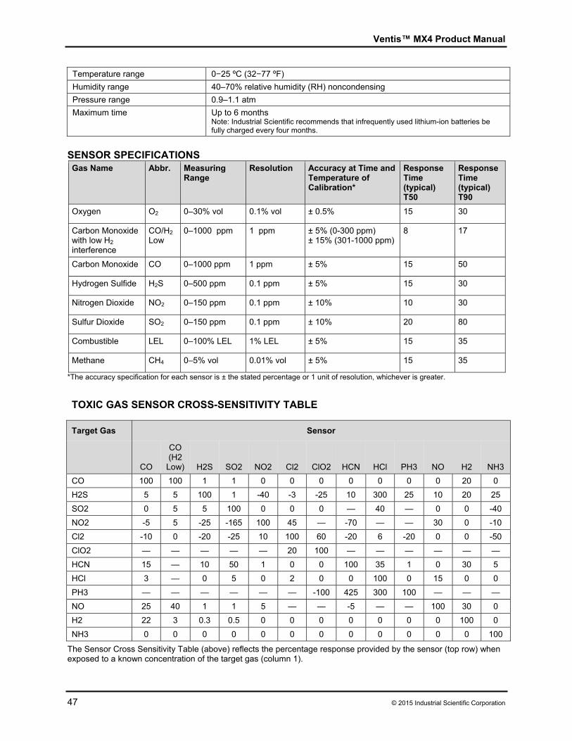
Ventis™ MX4 Product Manual
47 © 2015 Industrial Scientific Corporation
Temperature range 0−25 ºC (32−77 ºF)
Humidity range 40–70% relative humidity (RH) noncondensing
Pressure range 0.9–1.1 atm
Maximum time Up to 6 months Note: Industrial Scientific recommends that infrequently used lithium-ion batteries be fully charged every four months.
SENSOR SPECIFICATIONS Gas Name Abbr. Measuring
Range Resolution Accuracy at Time and
Temperature of Calibration*
Response Time (typical) T50
Response Time (typical) T90
Oxygen O2 0–30% vol 0.1% vol ± 0.5% 15 30
Carbon Monoxide with low H2 interference
CO/H2 Low
0–1000 ppm 1 ppm ± 5% (0-300 ppm) ± 15% (301-1000 ppm)
8 17
Carbon Monoxide CO 0–1000 ppm 1 ppm ± 5% 15 50
Hydrogen Sulfide H2S 0–500 ppm 0.1 ppm ± 5% 15 30
Nitrogen Dioxide NO2 0–150 ppm 0.1 ppm ± 10% 10 30
Sulfur Dioxide SO2 0–150 ppm 0.1 ppm ± 10% 20 80
Combustible LEL 0–100% LEL 1% LEL ± 5% 15 35
Methane CH4 0–5% vol 0.01% vol ± 5% 15 35
*The accuracy specification for each sensor is ± the stated percentage or 1 unit of resolution, whichever is greater.
TOXIC GAS SENSOR CROSS-SENSITIVITY TABLE
Target Gas Sensor
CO
CO (H2
Low) H2S SO2 NO2 Cl2 ClO2 HCN HCl PH3 NO H2 NH3
CO 100 100 1 1 0 0 0 0 0 0 0 20 0
H2S 5 5 100 1 -40 -3 -25 10 300 25 10 20 25
SO2 0 5 5 100 0 0 0 — 40 — 0 0 -40
NO2 -5 5 -25 -165 100 45 — -70 — — 30 0 -10
Cl2 -10 0 -20 -25 10 100 60 -20 6 -20 0 0 -50
ClO2 — — — — — 20 100 — — — — — —
HCN 15 — 10 50 1 0 0 100 35 1 0 30 5
HCl 3 — 0 5 0 2 0 0 100 0 15 0 0
PH3 — — — — — — -100 425 300 100 — — —
NO 25 40 1 1 5 — — -5 — — 100 30 0
H2 22 3 0.3 0.5 0 0 0 0 0 0 0 100 0
NH3 0 0 0 0 0 0 0 0 0 0 0 0 100
The Sensor Cross Sensitivity Table (above) reflects the percentage response provided by the sensor (top row) when exposed to a known concentration of the target gas (column 1).
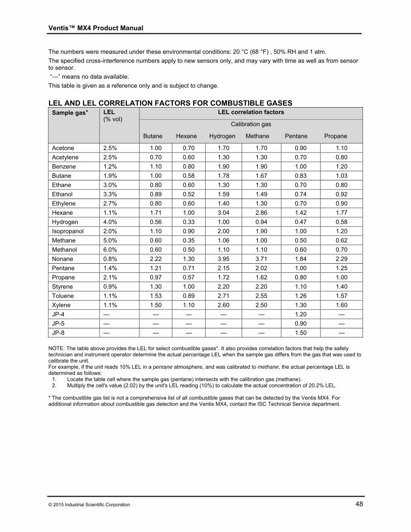
Ventis™ MX4 Product Manual
© 2015 Industrial Scientific Corporation 48
The numbers were measured under these environmental conditions: 20 °C (68 °F) , 50% RH and 1 atm.
The specified cross-interference numbers apply to new sensors only, and may vary with time as well as from sensor to sensor.
“—” means no data available.
This table is given as a reference only and is subject to change.
LEL AND LEL CORRELATION FACTORS FOR COMBUSTIBLE GASES
Sample gas*
LEL (% vol)
LEL correlation factors
Calibration gas
Butane Hexane Hydrogen Methane Pentane Propane
Acetone 2.5% 1.00 0.70 1.70 1.70 0.90 1.10
Acetylene 2.5% 0.70 0.60 1.30 1.30 0.70 0.80
Benzene 1.2% 1.10 0.80 1.90 1.90 1.00 1.20
Butane 1.9% 1.00 0.58 1.78 1.67 0.83 1.03
Ethane 3.0% 0.80 0.60 1.30 1.30 0.70 0.80
Ethanol 3.3% 0.89 0.52 1.59 1.49 0.74 0.92
Ethylene 2.7% 0.80 0.60 1.40 1.30 0.70 0.90
Hexane 1.1% 1.71 1.00 3.04 2.86 1.42 1.77
Hydrogen 4.0% 0.56 0.33 1.00 0.94 0.47 0.58
Isopropanol 2.0% 1.10 0.90 2.00 1.90 1.00 1.20
Methane 5.0% 0.60 0.35 1.06 1.00 0.50 0.62
Methanol 6.0% 0.60 0.50 1.10 1.10 0.60 0.70
Nonane 0.8% 2.22 1.30 3.95 3.71 1.84 2.29
Pentane 1.4% 1.21 0.71 2.15 2.02 1.00 1.25
Propane 2.1% 0.97 0.57 1.72 1.62 0.80 1.00
Styrene 0.9% 1.30 1.00 2.20 2.20 1.10 1.40
Toluene 1.1% 1.53 0.89 2.71 2.55 1.26 1.57
Xylene 1.1% 1.50 1.10 2.60 2.50 1.30 1.60
JP-4 — — — — — 1.20 —
JP-5 — — — — — 0.90 —
JP-8 — — — — — 1.50 —
NOTE: The table above provides the LEL for select combustible gases*. It also provides correlation factors that help the safety technician and instrument operator determine the actual percentage LEL when the sample gas differs from the gas that was used to calibrate the unit. For example, if the unit reads 10% LEL in a pentane atmosphere, and was calibrated to methane, the actual percentage LEL is determined as follows:
1. Locate the table cell where the sample gas (pentane) intersects with the calibration gas (methane). 2. Multiply the cell's value (2.02) by the unit's LEL reading (10%) to calculate the actual concentration of 20.2% LEL.
* The combustible gas list is not a comprehensive list of all combustible gases that can be detected by the Ventis MX4. For additional information about combustible gas detection and the Ventis MX4, contact the ISC Technical Service department.
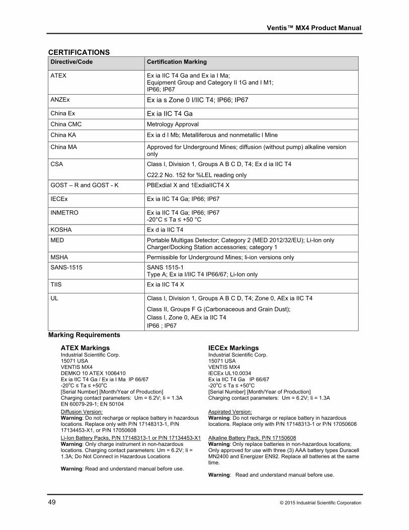
Ventis™ MX4 Product Manual
49 © 2015 Industrial Scientific Corporation
CERTIFICATIONS Directive/Code Certification Marking
ATEX Ex ia IIC T4 Ga and Ex ia I Ma; Equipment Group and Category II 1G and I M1; IP66; IP67
ANZEx Ex ia s Zone 0 I/IIC T4; IP66; IP67
China Ex Ex ia IIC T4 Ga
China CMC Metrology Approval
China KA Ex ia d I Mb; Metalliferous and nonmetallic l Mine
China MA Approved for Underground Mines; diffusion (without pump) alkaline version only
CSA Class I, Division 1, Groups A B C D, T4; Ex d ia IIC T4 C22.2 No. 152 for %LEL reading only
GOST – R and GOST - K PBExdiaI X and 1ExdiaIICT4 X
IECEx Ex ia IIC T4 Ga; IP66; IP67
INMETRO Ex ia IIC T4 Ga; IP66; IP67 -20°C ≤ Ta ≤ +50 °C
KOSHA Ex d ia IIC T4
MED Portable Multigas Detector; Category 2 (MED 2012/32/EU); Li-Ion only Charger/Docking Station accessories; category 1
MSHA Permissible for Underground Mines; li-ion versions only
SANS-1515 SANS 1515-1 Type A; Ex ia I/IIC T4 IP66/67; Li-Ion only
TIIS Ex ia IIC T4 X
UL Class I, Division 1, Groups A B C D, T4; Zone 0, AEx ia IIC T4 Class II, Groups F G (Carbonaceous and Grain Dust); Class I, Zone 0, AEx ia IIC T4 IP66 ; IP67
Marking Requirements
ATEX Markings Industrial Scientific Corp. 15071 USA VENTIS MX4 DEMKO 10 ATEX 1006410 Ex ia IIC T4 Ga / Ex ia I Ma IP 66/67 -20oC ≤ Ta ≤ +50oC [Serial Number] [Month/Year of Production] Charging contact parameters: Um = 6.2V; Ii = 1.3A EN 60079-29-1; EN 50104
IECEx Markings Industrial Scientific Corp. 15071 USA VENTIS MX4 IECEx UL10.0034 Ex ia IIC T4 Ga IP 66/67 -20oC ≤ Ta ≤ +50oC [Serial Number] [Month/Year of Production] Charging contact parameters: Um = 6.2V; Ii = 1.3A
Diffusion Version: Warning: Do not recharge or replace battery in hazardous locations. Replace only with P/N 17148313-1, P/N 17134453-X1, or P/N 17050608
Aspirated Version: Warning: Do not recharge or replace battery in hazardous locations. Replace only with P/N 17148313-1 or P/N 17050608
Li-Ion Battery Packs, P/N 17148313-1 or P/N 17134453-X1 Warning: Only charge instrument in non-hazardous locations. Charging contact parameters: Um = 6.2V; Ii = 1.3A; Do Not Connect in Hazardous Locations Warning: Read and understand manual before use.
Alkaline Battery Pack, P/N 17150608 Warning: Only replace batteries in non-hazardous locations; Only approved for use with three (3) AAA battery types Duracell MN2400 and Energizer EN92. Replace all batteries at the same time. Warning: Read and understand manual before use.
Ventis™ MX4 Product Manual
© 2015 Industrial Scientific Corporation 50
►Warranty Industrial Scientific Corporation's Ventis MX4 portable gas monitors are warranted to be free from defects in material and workmanship for a period of two years after purchase. This warranty includes the sensors, the pump, and the lithium-ion battery pack as shipped with the Ventis MX4. Filters are warranted to be free from defects in material and workmanship for 18 months from date of shipment, or one year from date of first use, whichever occurs first, except where otherwise stated in writing in Industrial Scientific literature. LIMITATION OF LIABILITY INDUSTRIAL SCIENTIFIC MAKES NO OTHER WARRANTIES, EITHER EXPRESSED OR IMPLIED, INCLUDING BUT NOT LIMITED TO THE WARRANTIES OF MERCHANTABILITY OR FITNESS FOR PARTICULAR PURPOSE. SHOULD THE PRODUCT FAIL TO CONFORM TO THE ABOVE WARRANTY, BUYER’S ONLY REMEDY AND INDUSTRIAL SCIENTIFIC’S ONLY OBLIGATION SHALL BE, AT INDUSTRIAL SCIENTIFIC’S SOLE OPTION, REPLACEMENT OR REPAIR OF SUCH NON-CONFORMING GOODS OR REFUND OF THE ORIGINAL PURCHASE PRICE OF THE NON-CONFORMING GOODS. IN NO EVENT WILL INDUSTRIAL SCIENTIFIC BE LIABLE FOR ANY OTHER SPECIAL, INCIDENTAL, OR CONSEQUENTIAL DAMAGES, INCLUDING LOSS OF PROFIT OR LOSS OF USE, ARISING OUT OF THE SALE, MANUFACTURE, OR USE OF ANY PRODUCTS SOLD HEREUNDER WHETHER SUCH CLAIM IS PLEADED IN CONTRACT OR IN TORT, INCLUDING STRICT LIABILITY IN TORT. It shall be an express condition to Industrial Scientific’s warranty that all products be carefully inspected for damage by Buyer upon receipt, be properly calibrated for Buyer’s particular use, and be used, repaired, and maintained in strict accordance with the instructions set forth in Industrial Scientific’s product literature. Repair or maintenance by non-qualified personnel will invalidate the warranty, as will the use of non-approved consumables or spare parts. As with any other sophisticated product, it is essential and a condition of Industrial Scientific’s warranty that all personnel using the products be fully acquainted with their use, capabilities, and limitations as set forth in the applicable product literature. Buyer acknowledges that it alone has determined the intended purpose and suitability of the goods purchased. It is expressly agreed by the parties that any technical or other advice given by Industrial Scientific with respect to the use of the goods or services is given without charge and at Buyer’s risk; therefore, Industrial Scientific assumes no obligations or liability for the advice given or results obtained.
Ventis™ MX4 Product Manual
51 © 2015 Industrial Scientific Corporation
►Ventis MX4 Resource Center Product documentation. Online training. And more! www.indsci.com/ventis
Contact Information Industrial Scientific Corporation 1 Life Way Pittsburgh, PA 15205-7500 USA Web: www.indsci.com Phone: +1 412-788-4353 or 1-800-DETECTS (338-3287) E-mail: [email protected] Fax: +1 412-788-8353 Industrial Scientific France S.A.S. 5 Rue Frédéric Degeorge, CS 80097 62002 Arras Cedex, France Web: www.indsci.com Phone: +33 (0)1 57 32 92 61 E-mail: [email protected] Fax: +33 (0)1 57 32 92 67 英思科传感仪器(上海)有限公司 地址:中国上海市浦东金桥出口加工区桂桥路290号 邮编:201206 电话:+86 21 5899 3279 传真:+86 21 5899 3280 E-mail: [email protected] 网址: www.indsci.com 服务热线:+86 400 820 2515
To locate a nearby distributor of our products or an Industrial Scientific service center or business office, visit us at www.indsci.com. Rendez-vous sur notre site Web www.indsci.com, si vous voulez trouver un distributeur de nos produits près de chez vous, ou, si vous recherchez un centre de service ou un bureau Industrial Scientific. Besuchen Sie uns unter www.indsci.com, um einen Vertriebshändler unserer Produkte oder ein Servicecenter bzw. eine Niederlassung von Industrial Scientific zu finden. Para buscar un distribuidor local de nuestros productos o un centro de servicio u oficina comercial de Industrial Scientific, visite www.indsci.com. 如需查找就近的产品经销商或 Industrial Scientific 服务中心或业务办事处,请访问我们的网
站 www.indsci.com。


![INDEX [zaffgroup.co]zaffgroup.co/wp-content/uploads/2018/06/Zaff-Profie.pdf · Ventis™ MX4 accessories. Configured for your safety, the highly configurable and I Net-compatible](https://static.documents.pub/doc/80x56/5f4e7eb5b6f9633f2c3be5c7/index-ventisa-mx4-accessories-configured-for-your-safety-the-highly-configurable.jpg)


