DULCOTEST ® Sensor CGE, Type: CGE 3-mA-2 ppm; CGE 3-mA-10 ppm Assembly and operating instructions A1953 EN 984482 BA DT 045 07/14 EN Please carefully read these operating instructions before use! · Do not discard! The operator shall be liable for any damage caused by installation or operating errors! Technical changes reserved.
Please carefully read these operating instructions before use! · Do not discard!The operator shall be liable for any damage caused by installation or operating errors!
Technical changes reserved.
General non-discriminatory approach
In order to make it easier to read, thisdocument uses the male form in grammat‐ical structures but with an implied neutralsense. It is aimed equally at both men andwomen. We kindly ask female readers fortheir understanding in this simplification ofthe text.
Supplementary information
Read the following supplementary infor‐mation in its entirety!
The following are highlighted separately inthe document:
n Enumerated lists
Instructions
ð Results of the instructions
Information
This provides important informationrelating to the correct operation of thesystem or is intended to make yourwork easier.
Safety information
Safety information are provided withdetailed descriptions of the endangeringsituation, see Ä Chapter 1.1 ‘Explanationof the safety information’ on page 4
Supplemental instructions
2
Table of contents1 Introduction............................................................................................................. 4
1.1 Explanation of the safety information............................................................. 41.2 Users' qualifications........................................................................................ 61.3 General safety information ............................................................................ 71.4 Intended Use.................................................................................................. 81.5 Information in the event of an emergency...................................................... 8
2 Brief Description of the Functions........................................................................... 92.1 Measured variable.......................................................................................... 92.2 Construction of the sensor........................................................................... 10
3 Transport and Storage.......................................................................................... 113.1 Storage ........................................................................................................ 113.2 Transport...................................................................................................... 11
6 Putting the Sensor into Operation......................................................................... 186.1 Calibration.................................................................................................... 19
7 Information on Troubleshooting and Fault Elimination......................................... 21
8 Maintenance and Repair Work on the Sensor...................................................... 23
9 Decommissioning and Disposal............................................................................ 24
1 IntroductionThese operating instructions provide infor‐mation on the technical data and functionsof the DULCOTEST ® Sensor for Organi‐cally Bound Chlorine, Type CGE 3.
Standard scope of supply
n Sensor complete with sensor cap,protective cap and clamp ring
n Bottle of electrolyten Spare membrane capn Operating instructionsn Screw driver
1.1 Explanation of the safetyinformation
Introduction
These operating instructions provide infor‐mation on the technical data and functionsof the product. These operating instruc‐tions provide detailed safety informationand are provided as clear step-by-stepinstructions.
The safety information and notes are cate‐gorised according to the followingscheme. A number of different symbolsare used to denote different situations.The symbols shown here serve only asexamples.
DANGER!
Nature and source of the dangerConsequence: Fatal or very seriousinjuries.
Measure to be taken to avoid thisdanger
Danger!
– Denotes an immediate threat‐ening danger. If this is disre‐garded, it will result in fatal orvery serious injuries.
WARNING!
Nature and source of the dangerPossible consequence: Fatal or veryserious injuries.
Measure to be taken to avoid thisdanger
Warning!
– Denotes a possibly hazardous sit‐uation. If this is disregarded, itcould result in fatal or veryserious injuries.
Introduction
4
CAUTION!
Nature and source of the dangerPossible consequence: Slight orminor injuries, material damage.
Measure to be taken to avoid thisdanger
Caution!
– Denotes a possibly hazardous sit‐uation. If this is disregarded, itcould result in slight or minor inju‐ries. May also be used as awarning about material damage.
NOTICE!
Nature and source of the dangerDamage to the product or its sur‐roundings
Measure to be taken to avoid thisdanger
Note!
– Denotes a possibly damaging sit‐uation. If this is disregarded, theproduct or an object in its vicinitycould be damaged.
Type of informationHints on use and additional informa‐tionSource of the information, additionalmeasuresInformation!– Denotes hints on use and other
useful information. It does notindicate a hazardous or dam‐aging situation.
Introduction
5
1.2 Users' qualifications
WARNING!
Danger of injury with inadequately qualified personnel!The operator of the plant / device is responsible for ensuring that the qualificationsare fulfilled.
If inadequately qualified personnel work on the unit or loiter in the hazard zone of theunit, this could result in dangers that could cause serious injuries and materialdamage.
– All work on the unit should therefore only be conducted by qualified personnel.– Unqualified personnel should be kept away from the hazard zone
Training Definition
Instructed personnel An instructed person is deemed to be a person who has beeninstructed and, if required, trained in the tasks assigned to him/her and possible dangers that could result from improperbehaviour, as well as having been instructed in the requiredprotective equipment and protective measures.
Trained user A trained user is a person who fulfils the requirements made ofan instructed person and who has also received additionaltraining specific to the system from ProMinent or anotherauthorised distribution partner.
Trained qualified per‐sonnel
A qualified employee is deemed to be a person who is able toassess the tasks assigned to him and recognize possible haz‐ards based on his/her training, knowledge and experience, aswell as knowledge of pertinent regulations. The assessment ofa person's technical training can also be based on severalyears of work in the relevant field.
Introduction
6
Training Definition
Electrician Electricians are deemed to be people, who are able to com‐plete work on electrical systems and recognize and avoid pos‐sible hazards independently based on his/her technical trainingand experience, as well as knowledge of pertinent standardsand regulations.
Electricians should be specifically trained for the working envi‐ronment in which the are employed and know the relevantstandards and regulations.
Electricians must comply with the provisions of the applicablestatutory directives on accident prevention.
Customer Servicedepartment
Customer Service department refers to service technicians,who have received proven training and have been authorisedby ProMinent to work on the system.
Note for the system operatorThe pertinent accident prevention regulations, as well as all other generally acknowl‐edged safety regulations, must be adhered to!
1.3 General safety information
WARNING!
Unauthorised access!Possible consequence: Fatal or veryserious injuries
– Measure: Ensure that there canbe no unauthorised access to theunit
– The sensor may only be fitted,installed, serviced and operatedby personnel trained for this
CAUTION!
Functional limitationsPossible consequence: Slight orminor injuries, material damage
– Check the sensor regularly for dirtand impurities
– Check the membrane cap regu‐larly for air bubbles adhering to it
– Observe all applicable nationalregulations relating to mainte‐nance, service and calibrationintervals.
Introduction
7
CAUTION!
Prerequisites for operationPossible consequence: Slight orminor injuries, material damage
– The sensor may only be used inflow gauges that ensure the cor‐rect flow parameters.
– There must be a free outlet or atmost a counter pressure of 1 barat the outlet of the flow gauge.The maximum operating pressureof the respective single compo‐nents must be observed.
– The sensor's voltage supply maynot be interrupted
– Following longer interruptions tothe voltage supply (> 2 h), allowthe sensor to run-in again andrecalibrate it
1.4 Intended Use
NOTICE!
Intended use– Only use the sensor to determine
and regulate the concentration offree chlorine or chlorine bound tocyanuric acid in swimming poolwater or water of a similar quality.
– Any other uses or modificationsto the system are prohibited
– The sensor is not a safety com‐ponent in the sense of DIN ENISO 13849-1:2008-12. If there isa critical process in your meas‐urement and control system, thenit is your responsibility to makesure this process is safe.
1.5 Information in the event ofan emergency
n In the event of an emergency, switchoff the controller
n If liquid escapes from the continuousflow gauge, close the stopcocks onthe inlet and outlet installed by thecustomer.
n Observe the plant operator's safetyinformation before opening the contin‐uous flow gauge.
Introduction
8
2 Brief Description of the FunctionsBrief description of the functions
The DULCOTEST® CGE is a membrane-covered, amperometric two-electrodesensor. Use the DULCOTEST® CGE tomeasure the concentration of total avail‐able chlorine in swimming pool water orwater of a similar quality.
The chlorine compounds dissolved in thewater pass through the sensor membraneand are electrochemically transformed onthe working electrode. The primary currentsignal resulting from the transformationcan be evaluated to determine the con‐centration (of chlorine).
The integral sensor signal transformerconverts the primary sensor current intoan output signal of 4 ... 20 mA.
Typical applications:
n Measurement of total availablechlorine in swimming pool water– from stabilised chlorine (chloro
(iso) cyanuric acid derivatives),also in combination with freechlorine from electrolysis pro‐cesses, with and without dia‐phragm between the anode andthe cathode.
2.1 Measured variableThe sensor measures the concentration oftotal available chlorine in swimming poolwater. This is understood as being thetotal chlorine, bound to organic carriermolecules (e.g. cyanuric acid) and theresulting free chlorine released (HOCl andOCl- ). The sensor measures independ‐ently of the content of combined chlorine(chloramines)
The measuring signal of the CGE3 sensorfollows the value determined by theDPD-1.
Brief Description of the Functions
9
2.2 Construction of the sensor
A1954
1.
2.
3.
4.
5.
6.
7.
8.
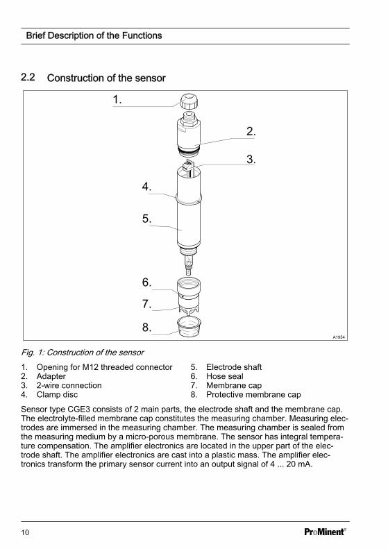
Fig. 1: Construction of the sensor1. Opening for M12 threaded connector2. Adapter3. 2-wire connection4. Clamp disc
5. Electrode shaft6. Hose seal7. Membrane cap8. Protective membrane cap
Sensor type CGE3 consists of 2 main parts, the electrode shaft and the membrane cap.The electrolyte-filled membrane cap constitutes the measuring chamber. Measuring elec‐trodes are immersed in the measuring chamber. The measuring chamber is sealed fromthe measuring medium by a micro-porous membrane. The sensor has integral tempera‐ture compensation. The amplifier electronics are located in the upper part of the elec‐trode shaft. The amplifier electronics are cast into a plastic mass. The amplifier elec‐tronics transform the primary sensor current into an output signal of 4 ... 20 mA.
Brief Description of the Functions
10
3 Transport and Storage
NOTICE!
Original packagingDamage to the product
– Only transport, ship and store thesensor in its original packaging
– Retain the packaging in itsentirety including the polystyreneinserts
NOTICE!
Maximum storage periodDamage to the product
If the sensor is stored for a longperiod of time, return it to ProMinentfor checking or servicing. Otherwisethe safe operation and measuringaccuracy of the sensor can no longerbe guaranteed
3.1 StoragePermissible ambient temperature: +5 °Cto +50 °C
Humidity: maximum 90 % relative airhumidity, non-condensing
Other: no dust, no direct sunlight
Maximum storage period of the electro‐lytes in their original packaging: see labelon the bottle
Maximum storage period of the sensor inits original packaging and normal atmos‐phere: 3 years
3.2 TransportThe sensor should be transported in itsoriginal packaging and in compliance withthe permissible environmental conditions.No further special conditions have to beobserved in relation to transport.
Transport and Storage
11
4 Assemblyn User qualification: trained user, see
Ä Chapter 1.2 ‘Users' qualifications’on page 6
Filling electrolyte
WARNING!
Danger from hazardous substances!Possible consequence: Fatal or veryserious injuries.
Please ensure when handling haz‐ardous substances that you haveread the latest safety data sheets pro‐vided by the manufacture of the haz‐ardous substance. The actionsrequired are described in the safetydata sheet. Check the safety datasheet regularly and replace, if neces‐sary, as the hazard potential of a sub‐stance can be re-evaluated at anytime based on new findings.
The system operator is responsiblefor ensuring that these safety datasheets are available and that they arekept up to date, as well as for pro‐ducing an associated hazard assess‐ment for the workstations affected.
Do not touch the membrane capand electrodes at the bottom of theelectrode shaftDo not touch or damage the mem‐brane at the bottom of the membranecap and the electrodes at the bottomof the electrode shaft or bring theminto contact with greasy substances.Otherwise the sensor will no longerwork accurately. Replace the mem‐brane cap with a new membrane capor send the sensor away to have theelectrodes cleaned.
Assembly
12
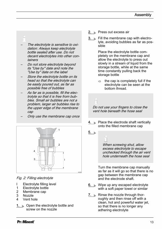
– The electrolyte is sensitive to oxi‐dation: Always keep electrolytebottle sealed after use. Do notdecant electrolytes into other con‐tainers
– Do not store electrolyte beyondits "Use by" date and note the"Use by" date on the label
– Store the electrolyte bottle on itshead so that the electrolyte canbe easily poured out, as far aspossible free of bubbles
– As far as is possible, fill the elec‐trolyte so that it is free from bub‐bles. Small air bubbles are not aproblem, larger air bubbles rise tothe upper edge of the membranecap
1. Open the electrolyte bottle andscrew on the nozzle
2. Press out excess air
3. Fill the membrane cap with electro‐lyte, avoiding bubbles as far as pos‐sible
Place the electrolyte bottle com‐pletely on the membrane cap andallow the electrolyte to press outslowly in a stream of liquid from thestorage bottle, while at the sametime constantly pulling back thestorage bottle
ð the cap is completely full if theelectrolyte can be seen at thebottom thread.
Do not use your fingers to close thevent hole beneath the hose seal
4. Place the electrode shaft verticallyonto the filled membrane cap
5.
When screwing shut, allowexcess electrolyte to escapeunchecked through the air venthole underneath the hose seal
Turn the membrane cap manuallyas far as it will go so that there is nogap between the membrane capand the electrode shaft.
6. Wipe up any escaped electrolytewith a soft paper towel or similar
7. Rinse the nozzle through thor‐oughly and then rinse off with aclean, hot and powerful water jet,so that there is no longer anyadhering electrolyte
Assembly
13
Installing the sensor in the in-line probehousing
Installation instructions– Only push in or pull out the
sensor slowly to or from the in-line probe housing. Otherwise themembrane could be damaged.
– Do not allow the membrane totouch the in-line probe housingflow resister
– Always keep the sensor moistafter commissioning, that is tosay never allow the flow gauge torun dry!
– Do not allow the flow to fall belowthe minimum flow rate. Monitorthe flow of the connected con‐troller. If the measured value isused for control, switch off thecontrol if the flow falls below theminimum flow rate and/or switchto basic load
– Only install the sensor in in-lineprobe housing type DLG III A,DLG III B or in DGM (25 mmmodule) to guarantee the neces‐sary flow requirements. No guar‐antee can be provided if other in-line probe housings are used
– Avoid installations that allow airbubbles to form in the samplewater– Air bubbles, which adhere to
the sensor's membrane, canresult in too low a measuredvalue and thus lead to incor‐rect metering in a control cir‐cuit
Observe the instructions and safetyinformation contained in the operatinginstructions for the in-line probehousing
1. Push the O-ring from below overthe sensor up to the clamp disc.
2. DLG III: Insert the sensor into theDLG III and tighten with thethreaded rod
Assembly
14
3. DGM: leave a washer in the DGM.Insert the sensor into the DGM andtighten securely with a clampingscrew until the O-ring seals
ð The correct insertion depth ofthe sensor is defined by theclamp disc.
Assembly
15
5 Installationn User qualification: trained qualified
Connection to external devicesPossible consequence: Fatal or veryserious injuries
– Ensure that the measuringdevice/control device connectedis galvanically isolated from thesensor
– Do not allow the supply voltage tofall below 16 V DC, even for shortperiods of time– Ensure that the current
source can be loaded with aminimum of 35 mA at a min‐imum of 16 V DC
– Too low a supply voltagemay result in an incorrectmeasured value
The interface requirements are auto‐matically met when connecting toProMinent control devices.
CAUTION!
Incorrect meteringPossible consequence: Slight orminor injuries. Material damage.
– Do not switch off the measuringsystem during intermittent opera‐tion– Switch on feeder assembly
with a time delay if necessary– Ensure that the water to be
measured always contains a suf‐ficient quantity of the appropriatefeed chemical– Otherwise you will have to
factor in longer run-in periods
Installation
16
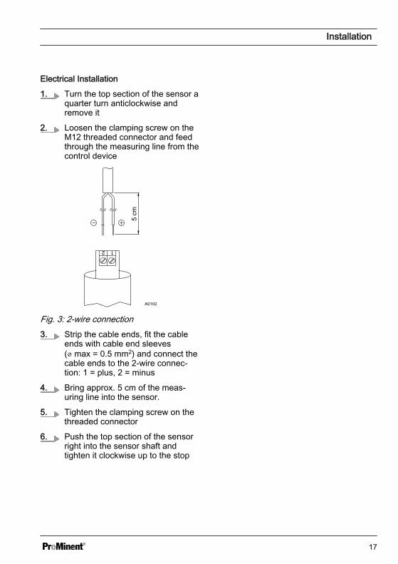
Electrical Installation
1. Turn the top section of the sensor aquarter turn anticlockwise andremove it
2. Loosen the clamping screw on theM12 threaded connector and feedthrough the measuring line from thecontrol device
A0102
Fig. 3: 2-wire connection3. Strip the cable ends, fit the cable
ends with cable end sleeves(⌀ max = 0.5 mm2) and connect thecable ends to the 2-wire connec‐tion: 1 = plus, 2 = minus
4. Bring approx. 5 cm of the meas‐uring line into the sensor.
5. Tighten the clamping screw on thethreaded connector
6. Push the top section of the sensorright into the sensor shaft andtighten it clockwise up to the stop
Installation
17
6 Putting the Sensor into Operationn User qualification: trained user, see Ä Chapter 1.2 ‘Users' qualifications’ on page 6
WARNING!
Danger from hazardous substances!Possible consequence: Fatal or very serious injuries.
Please ensure when handling hazardous substances that you have read the latestsafety data sheets provided by the manufacture of the hazardous substance. Theactions required are described in the safety data sheet. Check the safety data sheetregularly and replace, if necessary, as the hazard potential of a substance can be re-evaluated at any time based on new findings.
The system operator is responsible for ensuring that these safety data sheets areavailable and that they are kept up to date, as well as for producing an associatedhazard assessment for the workstations affected.
CAUTION!
Incorrect metering due to sensor failurePossible consequence: Slight or minor injuries. Material damage.
– If a sensor fails then there may be an incorrect measured value at the input ofthe controller/measuring instrument
– This may result in uncontrolled metering– The operator should therefore ensure that no subsequent damage results from
this
Putting the Sensor into Operation
18
CAUTION!
Incorrect metering due to premature ageing of the sensorPossible consequence: Slight or minor injuries. Material damage.
Measure: Do not electrically disconnect the sensor during measuring breaks.
Exception: If there is a break between measurements lasting more than a week andthe proportion of disinfectant in the sample water falls during this period to 0 ppmthen electrically disconnect the sensor.
– An extra run-in period will be necessary following operation without disinfectant.Switch on feeder assembly with a time delay if necessary.
Run-in period
The sensor requires a specific run-in period to display a steady display value.
Initial commissioning: 1 - 24 h (typically 6 h)*
Recommissioning: 1 - 24 h (typically 3 h)*
Electrolyte or membrane change: 3 h
* the exact run-in time depends on the application.
6.1 Calibration
CAUTION!
– Perform a slope calibration everytime if the sensor has been tam‐pered with (e.g. electrolytereplacement etc.)!
– Repeat slope calibration at reg‐ular intervals to ensure the per‐fect operation of the sensor! Ifthere are no other regulations,then only calibrate the sensorevery 3-4 weeks for use indrinking water and swimmingpool water.
Putting the Sensor into Operation
19
– Avoid air bubbles in the samplewater! Air bubbles, which adhereto the sensor membrane, canresult in too low a measuredvalue and thus lead to dangerousincorrect metering.
– Please note the pertinent nationalguidelines for calibration inter‐vals!
Prerequisites– The sensor is ready for meas‐
uring (wait for run-in period)– Constant flow rate at the in-line
probe housing– Constant temperature of the
sample water– Each time the sensor is removed
or inserted, wait until the run-inperiod has expired and a con‐stant measured value is ach‐ieved, a minimum of 15 minutesto avoid drifts caused by temper‐ature compensation.
– No concentration fluctuations ofthe feed chemical in the samplewater
– Constant pH value within the per‐missible range
– Ensure that the sample is takenat the place the sensor isinstalled
Zero point calibration
If the sensor is operated with a ProMinentcontroller, then zero point calibration is notgenerally necessary. Zero point calibrationis recommended if you wish to use thesensor at the lower threshold of the meas‐uring range.
1. Place the sensor in a vessel withclean water free of chlorine and oxi‐dising agent (e.g. mineral waterwithout gas).
2. Use the sensor to stir it until themeasured value on the controllerremains stable for 5 minutes.
3. Calibrate the controller to zero inaccordance with its operatinginstructions.
4. Refit the sensor into the in-lineprobe housing (DGM; DLG III).
Slope calibration
1. Use an appropriate referencemethod (e.g. DPD 1) to determinethe chlorine content of the samplewater.
2. Set the determined value on thecontroller in line with its operatinginstructions.
ð Repeat calibration during com‐missioning, and on the day fol‐lowing any tampering with thesensor.
Putting the Sensor into Operation
20
7 Information on Troubleshooting and Fault EliminationUser qualification: instructed user, see Ä Chapter 1.2 ‘Users' qualifications’ on page 6
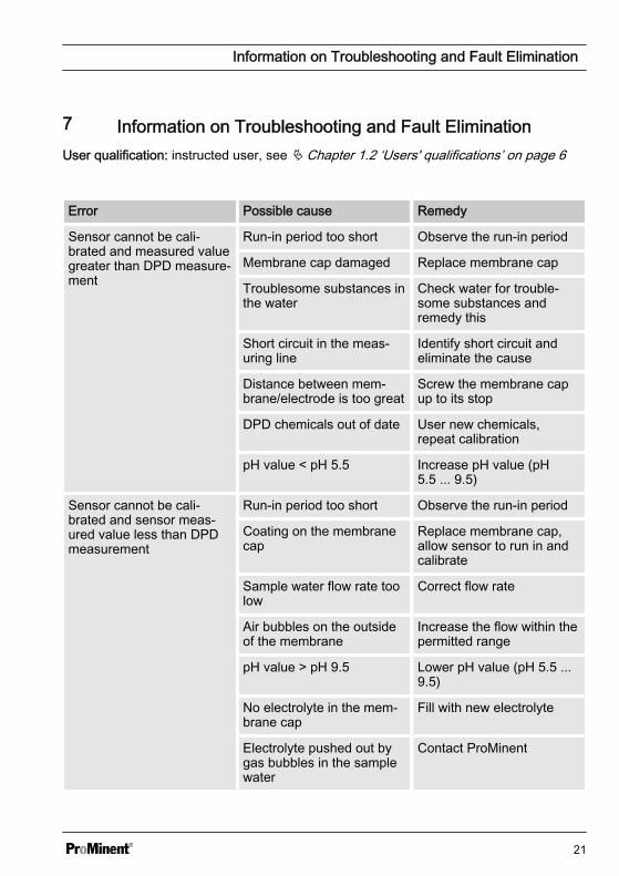
Error Possible cause Remedy
Sensor cannot be cali‐brated and measured valuegreater than DPD measure‐ment
Run-in period too short Observe the run-in period
Membrane cap damaged Replace membrane cap
Troublesome substances inthe water
Check water for trouble‐some substances andremedy this
Short circuit in the meas‐uring line
Identify short circuit andeliminate the cause
Distance between mem‐brane/electrode is too great
Screw the membrane capup to its stop
DPD chemicals out of date User new chemicals,repeat calibration
pH value < pH 5.5 Increase pH value (pH5.5 ... 9.5)
Sensor cannot be cali‐brated and sensor meas‐ured value less than DPDmeasurement
Run-in period too short Observe the run-in period
Coating on the membranecap
Replace membrane cap,allow sensor to run in andcalibrate
Sample water flow rate toolow
Correct flow rate
Air bubbles on the outsideof the membrane
Increase the flow within thepermitted range
pH value > pH 9.5 Lower pH value (pH 5.5 ...9.5)
No electrolyte in the mem‐brane cap
Fill with new electrolyte
Electrolyte pushed out bygas bubbles in the samplewater
Contact ProMinent
Information on Troubleshooting and Fault Elimination
21
Error Possible cause Remedy
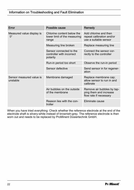
Measured value display is‘0’
Chlorine content below thelower limit of the measuringrange
Add chlorine and thenrepeat calibration and/oruse a suitable sensor
Measuring line broken Replace measuring line
Sensor connected to thecontroller with incorrectpolarity
Connect the sensor cor‐rectly to the controller
Run-in period too short Observe the run-in period
Sensor defective Send sensor in for regener‐ation
Sensor measured value isunstable
Membrane damaged Replace membrane cap;allow sensor to run in andcalibrate
Air bubbles on the outsideof the membrane
Remove air bubbles by tap‐ping them and increaseflow rate if necessary
Reason lies with the con‐troller
Eliminate cause
When you have tried everything: Check whether the reference electrode at the end of theelectrode shaft is silvery-white instead of brownish-grey. The reference electrode is thenworn out and needs to be replaced by ProMinent Dosiertechnik GmbH.
Information on Troubleshooting and Fault Elimination
22
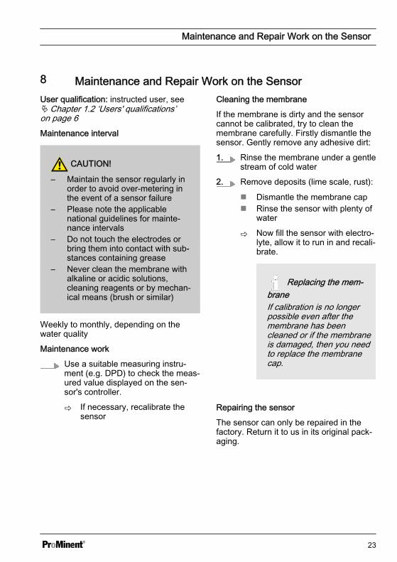
8 Maintenance and Repair Work on the SensorUser qualification: instructed user, seeÄ Chapter 1.2 ‘Users' qualifications’on page 6Maintenance interval
CAUTION!
– Maintain the sensor regularly inorder to avoid over-metering inthe event of a sensor failure
– Please note the applicablenational guidelines for mainte‐nance intervals
– Do not touch the electrodes orbring them into contact with sub‐stances containing grease
– Never clean the membrane withalkaline or acidic solutions,cleaning reagents or by mechan‐ical means (brush or similar)
Weekly to monthly, depending on thewater quality
Maintenance work
Use a suitable measuring instru‐ment (e.g. DPD) to check the meas‐ured value displayed on the sen‐sor's controller.
ð If necessary, recalibrate thesensor
Cleaning the membrane
If the membrane is dirty and the sensorcannot be calibrated, try to clean themembrane carefully. Firstly dismantle thesensor. Gently remove any adhesive dirt:
1. Rinse the membrane under a gentlestream of cold water
2. Remove deposits (lime scale, rust):
n Dismantle the membrane capn Rinse the sensor with plenty of
water
ð Now fill the sensor with electro‐lyte, allow it to run in and recali‐brate.
Replacing the mem‐braneIf calibration is no longerpossible even after themembrane has beencleaned or if the membraneis damaged, then you needto replace the membranecap.
Repairing the sensor
The sensor can only be repaired in thefactory. Return it to us in its original pack‐aging.
Maintenance and Repair Work on the Sensor
23
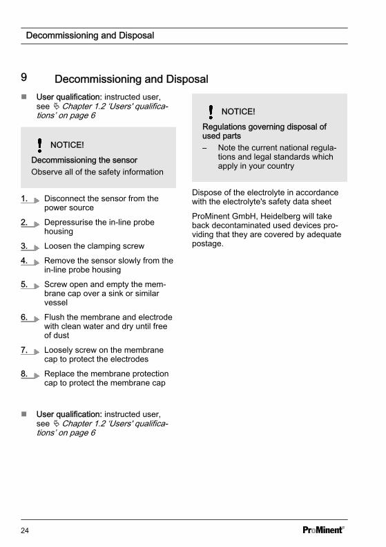
9 Decommissioning and Disposaln User qualification: instructed user,
see Ä Chapter 1.2 ‘Users' qualifica‐tions’ on page 6
NOTICE!
Decommissioning the sensorObserve all of the safety information
1. Disconnect the sensor from thepower source
2. Depressurise the in-line probehousing
3. Loosen the clamping screw
4. Remove the sensor slowly from thein-line probe housing
5. Screw open and empty the mem‐brane cap over a sink or similarvessel
6. Flush the membrane and electrodewith clean water and dry until freeof dust
7. Loosely screw on the membranecap to protect the electrodes
8. Replace the membrane protectioncap to protect the membrane cap
n User qualification: instructed user,see Ä Chapter 1.2 ‘Users' qualifica‐tions’ on page 6
NOTICE!
Regulations governing disposal ofused parts– Note the current national regula‐
tions and legal standards whichapply in your country
Dispose of the electrolyte in accordancewith the electrolyte's safety data sheet
ProMinent GmbH, Heidelberg will takeback decontaminated used devices pro‐viding that they are covered by adequatepostage.
Decommissioning and Disposal
24
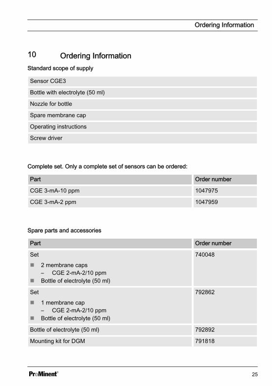
10 Ordering InformationStandard scope of supply
Sensor CGE3
Bottle with electrolyte (50 ml)
Nozzle for bottle
Spare membrane cap
Operating instructions
Screw driver
Complete set. Only a complete set of sensors can be ordered:
Part Order number
CGE 3-mA-10 ppm 1047975
CGE 3-mA-2 ppm 1047959
Spare parts and accessories
Part Order number
Set
n 2 membrane caps– CGE 2-mA-2/10 ppm
n Bottle of electrolyte (50 ml)
740048
Set
n 1 membrane cap– CGE 2-mA-2/10 ppm
n Bottle of electrolyte (50 ml)
792862
Bottle of electrolyte (50 ml) 792892
Mounting kit for DGM 791818
Ordering Information
25
Part Order number
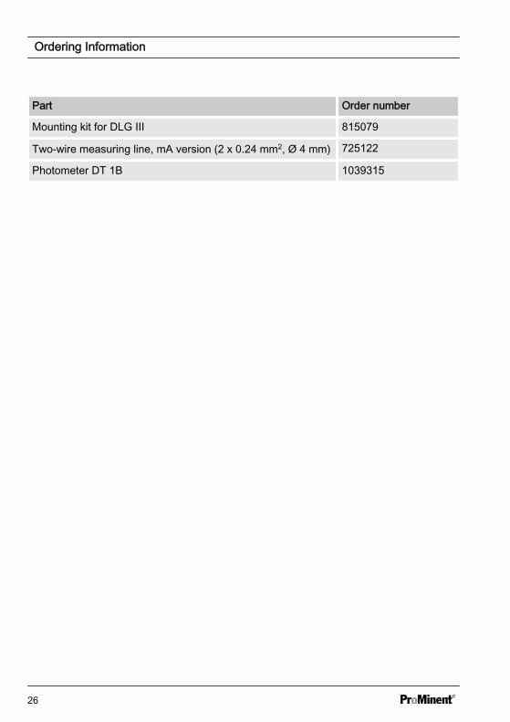
Mounting kit for DLG III 815079
Two-wire measuring line, mA version (2 x 0.24 mm2, Ø 4 mm) 725122
Photometer DT 1B 1039315
Ordering Information
26
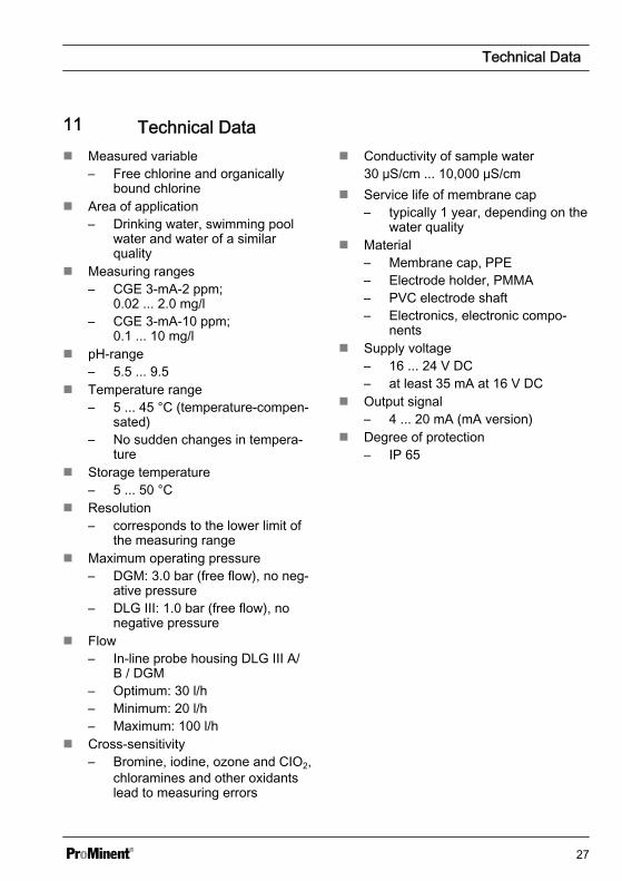
11 Technical Datan Measured variable
– Free chlorine and organicallybound chlorine
n Area of application– Drinking water, swimming pool
water and water of a similarquality
n Measuring ranges– CGE 3-mA-2 ppm;
0.02 ... 2.0 mg/l– CGE 3-mA-10 ppm;
0.1 ... 10 mg/ln pH-range
– 5.5 ... 9.5n Temperature range
– 5 ... 45 °C (temperature-compen‐sated)
– No sudden changes in tempera‐ture
n Storage temperature– 5 ... 50 °C
n Resolution– corresponds to the lower limit of
the measuring rangen Maximum operating pressure
– DGM: 3.0 bar (free flow), no neg‐ative pressure
– DLG III: 1.0 bar (free flow), nonegative pressure
ProMinent GmbHIm Schuhmachergewann 5 - 1169123 HeidelbergTelephone: +49 6221 842-0Fax: +49 6221 842-419email: [email protected]: www.prominent.comThe latest version of the operating instructions is available on our homepage.