208
DuraBluer Adhesive Melters Models D10 and D16 (Gerotor) Customer Product Manual Part 1073400A 04 Issued 4/15 NORDSON CORPORATION DULUTH, GEORGIA USA www.nordson.com

DuraBlue� Adhesive MeltersModels D10 and D16 (Gerotor)
Customer Product ManualPart 1073400A04
Issued 4/15
NORDSON CORPORATION DULUTH, GEORGIA USAwww.nordson.com

Part 1073400A04 � 2015 Nordson CorporationAll rights reserved
Nordson Corporation welcomes requests for information, comments, and inquiries about its products. General informationabout Nordson can be found on the Internet using the following address: http://www.nordson.com.
Address all correspondence to:
Nordson CorporationAttn: Customer Service11475 Lakefield Drive
Duluth, GA 30097
Notice
This is a Nordson Corporation publication which is protected by copyright. Original copyright date 2006.No part of this document may be photocopied, reproduced, or translated to another language without the prior written
consent of Nordson Corporation. The information contained in this publication is subject to change without notice.
Trademarks
AccuJet, AeroCharge, Apogee, AquaGuard, Asymtek, Automove, Baitgun, Blue Box, CanWorks, Century, CF, Clean Coat, CleanSleeve, CleanSpray,ColorMax, Control Coat, Coolwave, Cross-Cut, Cyclo-Kinetic, Dispensejet, DispenseMate, DuraBlue, Durafiber, Dura-Screen, Durasystem, Easy Coat,Easymove Plus, Ecodry, Econo-Coat, e.dot, EFD, e stylized, ETI, Excel 2000, Fillmaster, FlexiCoat, Flexi-Spray, Flex-O-Coat, Flow Sentry, Fluidmove,
FoamMelt, FoamMix, HDLV, Heli-flow, Helix, Horizon, Hot Shot, iControl, iFlow, Isocoil, Isocore, Iso-Flo, iTRAX, Kinetix, Little Squirt, LogiComm,Magnastatic, March, Maverick, MEG, Meltex, Microcoat, Micromark, MicroSet, Millennium, Mini Squirt, Mountaingate, MultiScan, Nordson, OptiMix,Package of Values, Pattern View, PermaFlo, Plasmod, Porous Coat, PowderGrid, Powderware, Printplus, Prism, ProBlue, Prodigy, Pro-Flo, ProLink,
Pro-Meter, Pro-Stream, RBX, Rhino, Saturn, Scoreguard, Seal Sentry, Select Charge, Select Coat, Select Cure, Slautterback, Smart-Coat, Solder Plus,Spectrum, Speed-Coat, SureBead, Sure Clean, Sure Coat, Sure-Max, Tracking Plus, TRAK, Trends, Tribomatic, TrueBlue, Ultra, Ultrasaver, UpTime,
Vantage, Veritec, VersaBlue, Versa-Coat, Versa-Screen, Versa-Spray, Walcom, Watermark, and When you expect more. are registered trademarks of Nordson Corporation.
Accubar, Advanced Plasma Systems, AeroDeck, AeroWash, AltaBlue, AquaCure, ATS, Auto-Flo, AutoScan, Best Choice, Blue Series, Check Mate,Classicblue, Color-on-Demand, Controlled Fiberization, Control Weave, CPX, CScan, DispensLink, Dry Cure, DuraBraid, DuraCoat, DuraDrum, DuraPail,Easy Clean, EasyOn, Eclipse, E-Nordson, EquiBead, ESP, FillEasy, Fill Sentry, FluxPlus, G−Net, G−Site,, iON, Iso-Flex, iTrend, Lacquer Cure, Lean Cell,
Maxima, MicroFin, MicroMax, Mikros, MiniBlue, MiniEdge, Minimeter, Multifil, Myritex, OptiStroke, Partnership+Plus, PatternJet, PatternPro, PCI,Powder Pilot, Powercure, Precise Coat, Primarc, Process Sentry, Pulse Spray, Quad Cure, Ready Coat, Royal Blue, Select Series, Sensomatic, Shaftshield,
SheetAire, Smart, SolidBlue, Spectral, Spectronic, SpeedKing, Spray Works, Summit, Sure Brand, SureMix, SureSeal, Sure Wrap, Swirl Coat, Tempus,Trade Plus, ThruWave, Ultrasmart, Universal, ValveMate, VersaDrum, VersaPail, Vista, Web Cure, and 2 Rings (Design)
are trademarks of Nordson Corporation.
Designations and trademarks stated in this document may be brands that, when used by third parties for their own purposes, could lead to violation of the owners’ rights.
DeviceNet is a trademark of Open DeviceNet Vendor Association, Inc.Parker Lubricant is a registered trademark of Parker Seal.
Profibus is a trademark of Profibus International.Viton is a registered trademark of DuPont Dow Elastomers. L.L.C.
Windows is a registered trademark of Microsoft Corporation.

Table of Contents i
Part 1073400A04� 2015 Nordson Corporation
Table of Contents
Safety 1-1. . . . . . . . . . . . . . . . . . . . . . . . . . . . . . . . . . . . . . . . . . . . . . . . . . . . .Safety Alert Symbols 1-1. . . . . . . . . . . . . . . . . . . . . . . . . . . . . . . . . . . . . . . . .Responsibilities of the Equipment Owner 1-2. . . . . . . . . . . . . . . . . . . . . . .
Safety Information 1-2. . . . . . . . . . . . . . . . . . . . . . . . . . . . . . . . . . . . . . . .Instructions, Requirements, and Standards 1-2. . . . . . . . . . . . . . . . . .User Qualifications 1-3. . . . . . . . . . . . . . . . . . . . . . . . . . . . . . . . . . . . . . .
Applicable Industry Safety Practices 1-3. . . . . . . . . . . . . . . . . . . . . . . . . . .Intended Use of the Equipment 1-3. . . . . . . . . . . . . . . . . . . . . . . . . . . . .Instructions and Safety Messages 1-3. . . . . . . . . . . . . . . . . . . . . . . . . .Installation Practices 1-4. . . . . . . . . . . . . . . . . . . . . . . . . . . . . . . . . . . . . .Operating Practices 1-4. . . . . . . . . . . . . . . . . . . . . . . . . . . . . . . . . . . . . . .Maintenance and Repair Practices 1-5. . . . . . . . . . . . . . . . . . . . . . . . . .
Equipment Safety Information 1-5. . . . . . . . . . . . . . . . . . . . . . . . . . . . . . . .Equipment Shutdown 1-6. . . . . . . . . . . . . . . . . . . . . . . . . . . . . . . . . . . . .
Relieving System Hydraulic Pressure 1-6. . . . . . . . . . . . . . . . . . . . .De-energizing the System 1-6. . . . . . . . . . . . . . . . . . . . . . . . . . . . . . .Disabling the Applicators 1-6. . . . . . . . . . . . . . . . . . . . . . . . . . . . . . . .
General Safety Warnings and Cautions 1-7. . . . . . . . . . . . . . . . . . . . . .Other Safety Precautions 1-10. . . . . . . . . . . . . . . . . . . . . . . . . . . . . . . . . .First Aid 1-10. . . . . . . . . . . . . . . . . . . . . . . . . . . . . . . . . . . . . . . . . . . . . . . . .
Safety Labels and Tags 1-10. . . . . . . . . . . . . . . . . . . . . . . . . . . . . . . . . . . . . .
Introduction 2-1. . . . . . . . . . . . . . . . . . . . . . . . . . . . . . . . . . . . . . . . . . . . . . . .Other Sources of Information 2-2. . . . . . . . . . . . . . . . . . . . . . . . . . . . . . . . .
Installation Guide 2-2. . . . . . . . . . . . . . . . . . . . . . . . . . . . . . . . . . . . . . .User’s Guide 2-2. . . . . . . . . . . . . . . . . . . . . . . . . . . . . . . . . . . . . . . . . . .Online Support 2-2. . . . . . . . . . . . . . . . . . . . . . . . . . . . . . . . . . . . . . . . .Product Resource CD 2-2. . . . . . . . . . . . . . . . . . . . . . . . . . . . . . . . . . .
Product Description 2-3. . . . . . . . . . . . . . . . . . . . . . . . . . . . . . . . . . . . . . . . .Intended Use 2-4. . . . . . . . . . . . . . . . . . . . . . . . . . . . . . . . . . . . . . . . . . . .Limitations of Use 2-4. . . . . . . . . . . . . . . . . . . . . . . . . . . . . . . . . . . . . . . .Modes of Operation 2-4. . . . . . . . . . . . . . . . . . . . . . . . . . . . . . . . . . . . . . .Melter Identification 2-5. . . . . . . . . . . . . . . . . . . . . . . . . . . . . . . . . . . . . . .
Key Components 2-6. . . . . . . . . . . . . . . . . . . . . . . . . . . . . . . . . . . . . . . . . . .Optional Equipment 2-8. . . . . . . . . . . . . . . . . . . . . . . . . . . . . . . . . . . . . . . . .

Table of Contentsii
Part 1073400A04 � 2015 Nordson Corporation
Installation 3-1. . . . . . . . . . . . . . . . . . . . . . . . . . . . . . . . . . . . . . . . . . . . . . . . .Quick-Start 3-1. . . . . . . . . . . . . . . . . . . . . . . . . . . . . . . . . . . . . . . . . . . . . . . . .Overview 3-1. . . . . . . . . . . . . . . . . . . . . . . . . . . . . . . . . . . . . . . . . . . . . . . . . .
Additional Information 3-2. . . . . . . . . . . . . . . . . . . . . . . . . . . . . . . . . . . . .Installation Tasks 3-2. . . . . . . . . . . . . . . . . . . . . . . . . . . . . . . . . . . . . . . . .Experience of Installation Personnel 3-2. . . . . . . . . . . . . . . . . . . . . . . . .
Installation Requirements 3-3. . . . . . . . . . . . . . . . . . . . . . . . . . . . . . . . . . . .Clearances 3-3. . . . . . . . . . . . . . . . . . . . . . . . . . . . . . . . . . . . . . . . . . . . . .Electrical Power 3-4. . . . . . . . . . . . . . . . . . . . . . . . . . . . . . . . . . . . . . . . . .Other Considerations 3-4. . . . . . . . . . . . . . . . . . . . . . . . . . . . . . . . . . . . .
Unpacking the Melter 3-6. . . . . . . . . . . . . . . . . . . . . . . . . . . . . . . . . . . . . . . .Contents of the Installation Kit 3-6. . . . . . . . . . . . . . . . . . . . . . . . . . . . . .Customer-Supplied Materials 3-6. . . . . . . . . . . . . . . . . . . . . . . . . . . . . .
Mounting the Melter 3-8. . . . . . . . . . . . . . . . . . . . . . . . . . . . . . . . . . . . . . . . .Configuring the Electrical Service 3-10. . . . . . . . . . . . . . . . . . . . . . . . . . . . .Connecting Hoses and Applicators 3-14. . . . . . . . . . . . . . . . . . . . . . . . . . . .Setting Up the Melter 3-16. . . . . . . . . . . . . . . . . . . . . . . . . . . . . . . . . . . . . . . .
Quick Setup 3-16. . . . . . . . . . . . . . . . . . . . . . . . . . . . . . . . . . . . . . . . . . . . .Operating Parameters 3-18. . . . . . . . . . . . . . . . . . . . . . . . . . . . . . . . . . . . .
Selecting Operating Parameters 3-18. . . . . . . . . . . . . . . . . . . . . . . . . .Reading or Editing Operating Parameters 3-19. . . . . . . . . . . . . . . . .
Setpoint Temperature of the Tank, Hoses, and Applicators 3-24. . . . . .Save and Restore Melter Settings 3-26. . . . . . . . . . . . . . . . . . . . . . . . . . .Review Parameter and Setpoint Temperature Changes 3-28. . . . . . . .
Installing Melter Inputs 3-30. . . . . . . . . . . . . . . . . . . . . . . . . . . . . . . . . . . . . . .Installing Melter Outputs 3-34. . . . . . . . . . . . . . . . . . . . . . . . . . . . . . . . . . . . .Installing Optional Equipment 3-37. . . . . . . . . . . . . . . . . . . . . . . . . . . . . . . . .Connecting a Applicator Driver, Pattern Controller, or Timer 3-37. . . . . . .Flushing the Melter 3-37. . . . . . . . . . . . . . . . . . . . . . . . . . . . . . . . . . . . . . . . . .Adjusting the Pressure Control Valve 3-38. . . . . . . . . . . . . . . . . . . . . . . . . .Setting Up Melter Communications 3-38. . . . . . . . . . . . . . . . . . . . . . . . . . . .
Operation 4-1. . . . . . . . . . . . . . . . . . . . . . . . . . . . . . . . . . . . . . . . . . . . . . . . . .Additional Information 4-1. . . . . . . . . . . . . . . . . . . . . . . . . . . . . . . . . . . . . . .
More about Heated Components 4-2. . . . . . . . . . . . . . . . . . . . . . . . . . .Filling the Tank 4-3. . . . . . . . . . . . . . . . . . . . . . . . . . . . . . . . . . . . . . . . . . . . . .Starting the Melter 4-4. . . . . . . . . . . . . . . . . . . . . . . . . . . . . . . . . . . . . . . . . .Monitoring the Melter 4-6. . . . . . . . . . . . . . . . . . . . . . . . . . . . . . . . . . . . . . . .
Confirm that the Melter is Operating Correctly 4-6. . . . . . . . . . . . . . . .Monitor Component Temperatures 4-7. . . . . . . . . . . . . . . . . . . . . . . . . .Monitor Melter Faults 4-10. . . . . . . . . . . . . . . . . . . . . . . . . . . . . . . . . . . . .
How F1, F2, and F3 Faults are Handled 4-12. . . . . . . . . . . . . . . . . . .How F4 Faults are Handled 4-13. . . . . . . . . . . . . . . . . . . . . . . . . . . . .
Monitor the Service Interval 4-18. . . . . . . . . . . . . . . . . . . . . . . . . . . . . . . .Adjusting Component Temperatures 4-20. . . . . . . . . . . . . . . . . . . . . . . . . . .Entering the Melter Password 4-24. . . . . . . . . . . . . . . . . . . . . . . . . . . . . . . .Using Melter Function Keys 4-26. . . . . . . . . . . . . . . . . . . . . . . . . . . . . . . . . .
Heater Key 4-26. . . . . . . . . . . . . . . . . . . . . . . . . . . . . . . . . . . . . . . . . . . . . .Pump Key 4-26. . . . . . . . . . . . . . . . . . . . . . . . . . . . . . . . . . . . . . . . . . . . . . .Setup Key 4-27. . . . . . . . . . . . . . . . . . . . . . . . . . . . . . . . . . . . . . . . . . . . . . .Seven-day Clock Key 4-27. . . . . . . . . . . . . . . . . . . . . . . . . . . . . . . . . . . . .Standby Key 4-28. . . . . . . . . . . . . . . . . . . . . . . . . . . . . . . . . . . . . . . . . . . . .
Shutting Down the Melter 4-29. . . . . . . . . . . . . . . . . . . . . . . . . . . . . . . . . . . .

Table of Contents iii
Part 1073400A04� 2015 Nordson Corporation
Maintenance 5-1. . . . . . . . . . . . . . . . . . . . . . . . . . . . . . . . . . . . . . . . . . . . . . .Relieving System Pressure 5-2. . . . . . . . . . . . . . . . . . . . . . . . . . . . . . . . . . .Locking Out External Communications 5-2. . . . . . . . . . . . . . . . . . . . . . . . .Cleaning the Melter 5-4. . . . . . . . . . . . . . . . . . . . . . . . . . . . . . . . . . . . . . . . .Replacing the Filter 5-6. . . . . . . . . . . . . . . . . . . . . . . . . . . . . . . . . . . . . . . . .Cleaning the Tank 5-8. . . . . . . . . . . . . . . . . . . . . . . . . . . . . . . . . . . . . . . . . . .
Troubleshooting 6-1. . . . . . . . . . . . . . . . . . . . . . . . . . . . . . . . . . . . . . . . . . . .Safety 6-1. . . . . . . . . . . . . . . . . . . . . . . . . . . . . . . . . . . . . . . . . . . . . . . . . . . . . .Melter Faults 6-2. . . . . . . . . . . . . . . . . . . . . . . . . . . . . . . . . . . . . . . . . . . . . . .Pump Operating Variables 6-4. . . . . . . . . . . . . . . . . . . . . . . . . . . . . . . . . . .Using the Troubleshooting Flow Chart 6-6. . . . . . . . . . . . . . . . . . . . . . . . .
Troubleshooting Quick-checks 6-6. . . . . . . . . . . . . . . . . . . . . . . . . . . . . .Returning the Melter Setup to Factory Settings 6-7. . . . . . . . . . . . . . .Identifying Electrical Components 6-7. . . . . . . . . . . . . . . . . . . . . . . . . . .
DuraBlue Troubleshooting Charts 6-13. . . . . . . . . . . . . . . . . . . . . . . . . . . . .
Parts 7-1. . . . . . . . . . . . . . . . . . . . . . . . . . . . . . . . . . . . . . . . . . . . . . . . . . . . . .Using the Illustrated Parts List 7-1. . . . . . . . . . . . . . . . . . . . . . . . . . . . . . . .Front Panel Service Kits 7-2. . . . . . . . . . . . . . . . . . . . . . . . . . . . . . . . . . . . .Electrical Component Service Kits 7-4. . . . . . . . . . . . . . . . . . . . . . . . . . . . .
Circuit Boards 7-4. . . . . . . . . . . . . . . . . . . . . . . . . . . . . . . . . . . . . . . . . . . .Fuses 7-6. . . . . . . . . . . . . . . . . . . . . . . . . . . . . . . . . . . . . . . . . . . . . . . . . . .Thermostat 7-7. . . . . . . . . . . . . . . . . . . . . . . . . . . . . . . . . . . . . . . . . . . . . .RTDs 7-7. . . . . . . . . . . . . . . . . . . . . . . . . . . . . . . . . . . . . . . . . . . . . . . . . . .Heaters 7-7. . . . . . . . . . . . . . . . . . . . . . . . . . . . . . . . . . . . . . . . . . . . . . . . .Cables and Harnesses 7-7. . . . . . . . . . . . . . . . . . . . . . . . . . . . . . . . . . . .
Tank Strainer 7-8. . . . . . . . . . . . . . . . . . . . . . . . . . . . . . . . . . . . . . . . . . . . . . .Drive Assembly Service Kits 7-9. . . . . . . . . . . . . . . . . . . . . . . . . . . . . . . . . .
Motor 7-10. . . . . . . . . . . . . . . . . . . . . . . . . . . . . . . . . . . . . . . . . . . . . . . . . . .Pump 7-12. . . . . . . . . . . . . . . . . . . . . . . . . . . . . . . . . . . . . . . . . . . . . . . . . . .Manifold 7-14. . . . . . . . . . . . . . . . . . . . . . . . . . . . . . . . . . . . . . . . . . . . . . . . .Drive Assembly (Complete) 7-16. . . . . . . . . . . . . . . . . . . . . . . . . . . . . . . .
Optional Equipment 7-18. . . . . . . . . . . . . . . . . . . . . . . . . . . . . . . . . . . . . . . . .Flow/Pressure Control and Pressure Indication 7-18. . . . . . . . . . . . . . .Expansion and Control Kits 7-18. . . . . . . . . . . . . . . . . . . . . . . . . . . . . . . .FillMaster Accessory Kits 7-18. . . . . . . . . . . . . . . . . . . . . . . . . . . . . . . . . .General Melter Accessory Kits 7-18. . . . . . . . . . . . . . . . . . . . . . . . . . . . .
Technical Data 8-1. . . . . . . . . . . . . . . . . . . . . . . . . . . . . . . . . . . . . . . . . . . . .General Specifications 8-1. . . . . . . . . . . . . . . . . . . . . . . . . . . . . . . . . . . . . . .Electrical Specifications 8-2. . . . . . . . . . . . . . . . . . . . . . . . . . . . . . . . . . . . . .Heater Specifications 8-2. . . . . . . . . . . . . . . . . . . . . . . . . . . . . . . . . . . . . . . .Motor and Pump Specifications 8-3. . . . . . . . . . . . . . . . . . . . . . . . . . . . . . .Dimensions 8-4. . . . . . . . . . . . . . . . . . . . . . . . . . . . . . . . . . . . . . . . . . . . . . . .Conduit Penetration Sizes 8-5. . . . . . . . . . . . . . . . . . . . . . . . . . . . . . . . . . . .

Table of Contentsiv
Part 1073400A04 � 2015 Nordson Corporation
Calculating Melter Power Requirements A-1. . . . . . . . . . . . . . . . . . . . .
Operating Parameters B-1. . . . . . . . . . . . . . . . . . . . . . . . . . . . . . . . . . . . . .Standard B-2. . . . . . . . . . . . . . . . . . . . . . . . . . . . . . . . . . . . . . . . . . . . . . . . . . .Pressure Control B-7. . . . . . . . . . . . . . . . . . . . . . . . . . . . . . . . . . . . . . . . . . . .Temperature Control B-8. . . . . . . . . . . . . . . . . . . . . . . . . . . . . . . . . . . . . . . .Input Setup B-11. . . . . . . . . . . . . . . . . . . . . . . . . . . . . . . . . . . . . . . . . . . . . . . .Output Setup B-14. . . . . . . . . . . . . . . . . . . . . . . . . . . . . . . . . . . . . . . . . . . . . . .Seven-day Clock B-16. . . . . . . . . . . . . . . . . . . . . . . . . . . . . . . . . . . . . . . . . . . .
Example 1 B-17. . . . . . . . . . . . . . . . . . . . . . . . . . . . . . . . . . . . . . . . . . . .Example 2 B-17. . . . . . . . . . . . . . . . . . . . . . . . . . . . . . . . . . . . . . . . . . . .Example 3 B-17. . . . . . . . . . . . . . . . . . . . . . . . . . . . . . . . . . . . . . . . . . . .
Automatic Fill Timer B-26. . . . . . . . . . . . . . . . . . . . . . . . . . . . . . . . . . . . . . . . .PID Selection B-26. . . . . . . . . . . . . . . . . . . . . . . . . . . . . . . . . . . . . . . . . . . . . . .
Melter Communications C-1. . . . . . . . . . . . . . . . . . . . . . . . . . . . . . . . . . . . .Software Availability C-1. . . . . . . . . . . . . . . . . . . . . . . . . . . . . . . . . . . . . . . . .System Requirements C-1. . . . . . . . . . . . . . . . . . . . . . . . . . . . . . . . . . . . . . .Installing the Software C-2. . . . . . . . . . . . . . . . . . . . . . . . . . . . . . . . . . . . . . .
Removing the Software from Your PC C-3. . . . . . . . . . . . . . . . . . . . . . . .Connecting the PC and the Melter C-4. . . . . . . . . . . . . . . . . . . . . . . . . . . .Using Nordson Configuration Manager C-4. . . . . . . . . . . . . . . . . . . . . . . . .
Saving and Restoring Melter Settings C-5. . . . . . . . . . . . . . . . . . . . . . .Upgrading or Restoring Melter Firmware C-6. . . . . . . . . . . . . . . . . . . . .
Troubleshooting C-9. . . . . . . . . . . . . . . . . . . . . . . . . . . . . . . . . . . . . . . . . . . .Using Nordson Configuration Manager C-9. . . . . . . . . . . . . . . . . . . . . .

Safety 1-1
A1EN−01−[XX−SAFE]−10� 2015 Nordson Corporation Issued 4-02
Section 1Safety
Read this section before using the equipment. This section containsrecommendations and practices applicable to the safe installation,operation, and maintenance (hereafter referred to as “use”) of the productdescribed in this document (hereafter referred to as “equipment”). Additionalsafety information, in the form of task-specific safety alert messages,appears as appropriate throughout this document.
WARNING: Failure to follow the safety messages, recommendations, andhazard avoidance procedures provided in this document can result inpersonal injury, including death, or damage to equipment or property.
Safety Alert SymbolsThe following safety alert symbol and signal words are used throughout thisdocument to alert the reader to personal safety hazards or to identifyconditions that may result in damage to equipment or property. Comply withall safety information that follows the signal word.
WARNING: Indicates a potentially hazardous situation that, if not avoided,can result in serious personal injury, including death.
CAUTION: Indicates a potentially hazardous situation that, if not avoided,can result in minor or moderate personal injury.
CAUTION: (Used without the safety alert symbol) Indicates a potentiallyhazardous situation that, if not avoided, can result in damage to equipmentor property.

Safety1-2
A1EN−01−[XX−SAFE]−10 � 2015 Nordson CorporationIssued 4-02
Responsibilities of the Equipment Owner Equipment owners are responsible for managing safety information,ensuring that all instructions and regulatory requirements for use of theequipment are met, and for qualifying all potential users.
Safety Information � Research and evaluate safety information from all applicable sources,
including the owner-specific safety policy, best industry practices,governing regulations, material manufacturer’s product information, andthis document.
� Make safety information available to equipment users in accordancewith governing regulations. Contact the authority having jurisdiction forinformation.
� Maintain safety information, including the safety labels affixed to theequipment, in readable condition.
Instructions, Requirements, and Standards � Ensure that the equipment is used in accordance with the information
provided in this document, governing codes and regulations, and bestindustry practices.
� If applicable, receive approval from your facility’s engineering or safetydepartment, or other similar function within your organization, beforeinstalling or operating the equipment for the first time.
� Provide appropriate emergency and first aid equipment.
� Conduct safety inspections to ensure required practices are beingfollowed.
� Re-evaluate safety practices and procedures whenever changes aremade to the process or equipment.

Safety 1-3
A1EN−01−[XX−SAFE]−10� 2015 Nordson Corporation Issued 4-02
User Qualifications Equipment owners are responsible for ensuring that users:
� receive safety training appropriate to their job function as directed bygoverning regulations and best industry practices
� are familiar with the equipment owner’s safety and accidentprevention policies and procedures
� receive, equipment- and task-specific training from another qualifiedindividual
NOTE: Nordson can provide equipment-specific installation,operation, and maintenance training. Contact your Nordsonrepresentative for information
� possess industry- and trade-specific skills and a level of experienceappropriate to their job function
� are physically capable of performing their job function and are notunder the influence of any substance that degrades their mentalcapacity or physical capabilities
Applicable Industry Safety Practices The following safety practices apply to the use of the equipment in themanner described in this document. The information provided here is notmeant to include all possible safety practices, but represents the best safetypractices for equipment of similar hazard potential used in similar industries.
Intended Use of the Equipment � Use the equipment only for the purposes described and within the limits
specified in this document.
� Do not modify the equipment.
� Do not use incompatible materials or unapproved auxiliary devices.Contact your Nordson representative if you have any questions onmaterial compatibility or the use of non-standard auxiliary devices.
Instructions and Safety Messages � Read and follow the instructions provided in this document and other
referenced documents.
� Familiarize yourself with the location and meaning of the safety warninglabels and tags affixed to the equipment. Refer to Safety Labels andTags at the end of this section.
� If you are unsure of how to use the equipment, contact your Nordsonrepresentative for assistance.

Safety1-4
A1EN−01−[XX−SAFE]−10 � 2015 Nordson CorporationIssued 4-02
Installation Practices � Install the equipment in accordance with the instructions provided in this
document and in the documentation provided with auxiliary devices.
� Ensure that the equipment is rated for the environment in which it will beused and that the processing characteristics of the material will notcreate a hazardous environment. Refer to the Safety Data Sheet (SDS)for the material.
� If the required installation configuration does not match the installationinstructions, contact your Nordson representative for assistance.
� Position the equipment for safe operation. Observe the requirements forclearance between the equipment and other objects.
� Install lockable power disconnects to isolate the equipment and allindependently powered auxiliary devices from their power sources.
� Properly ground all equipment. Contact your local building codeenforcement agency for specific requirements.
� Ensure that fuses of the correct type and rating are installed in fusedequipment.
� Contact the authority having jurisdiction to determine the requirement forinstallation permits or inspections.
Operating Practices � Familiarize yourself with the location and operation of all safety devices
and indicators.
� Confirm that the equipment, including all safety devices (guards,interlocks, etc.), is in good working order and that the requiredenvironmental conditions exist.
� Use the personal protective equipment (PPE) specified for each task.Refer to Equipment Safety Information or the material manufacturer’sinstructions and SDS for PPE requirements.
� Do not use equipment that is malfunctioning or shows signs of apotential malfunction.

Safety 1-5
A1EN−01−[XX−SAFE]−10� 2015 Nordson Corporation Issued 4-02
Maintenance and Repair Practices � Perform scheduled maintenance activities at the intervals described in
this document.
� Relieve system hydraulic and pneumatic pressure before servicing theequipment.
� De-energize the equipment and all auxiliary devices before servicing theequipment.
� Use only new factory-authorized refurbished or replacement parts.
� Read and comply with the manufacturer’s instructions and the SDSsupplied with equipment cleaning compounds.
NOTE: SDSs for cleaning compounds that are sold by Nordson areavailable at www.nordson.com or by calling your Nordsonrepresentative.
� Confirm the correct operation of all safety devices before placing theequipment back into operation.
� Dispose of waste cleaning compounds and residual process materialsaccording to governing regulations. Refer to the applicable SDS orcontact the authority having jurisdiction for information.
� Keep equipment safety warning labels clean. Replace worn or damagedlabels.
Equipment Safety Information This equipment safety information is applicable to the following types ofNordson equipment:
� hot melt and cold adhesive application equipment and all relatedaccessories
� pattern controllers, timers, detection and verification systems, and allother optional process control devices

Safety1-6
A1EN−01−[XX−SAFE]−10 � 2015 Nordson CorporationIssued 4-02
Equipment Shutdown To safely complete many of the procedures described in this document, theequipment must first be shut down. The level of shut down required variesby the type of equipment in use and the procedure being completed. If required, shut down instructions are specified at the start of theprocedure. The levels of shut down are:
Relieving System Hydraulic Pressure Completely relieve system hydraulic pressure before breaking any hydraulicconnection or seal. Refer to the melter-specific product manual forinstructions on relieving system hydraulic pressure.
De-energizing the System Isolate the system (melter, hoses, applicators, and optional devices) from allpower sources before accessing any unprotected high-voltage wiring orconnection point.
1. Turn off the equipment and all auxiliary devices connected to theequipment (system).
2. To prevent the equipment from being accidentally energized, lock andtag the disconnect switch(es) or circuit breaker(s) that provide inputelectrical power to the equipment and optional devices.
NOTE: Government regulations and industry standards dictate specificrequirements for the isolation of hazardous energy sources. Refer to theappropriate regulation or standard.
Disabling the Applicators All electrical or mechanical devices that provide an activation signal to theapplicators, applicator solenoid valve(s), or the melter pump must bedisabled before work can be performed on or around a applicator that isconnected to a pressurized system.
1. Turn off or disconnect the applicator triggering device (pattern controller,timer, PLC, etc.).
2. Disconnect the input signal wiring to the applicator solenoid valve(s).
3. Reduce the air pressure to the applicator solenoid valve(s) to zero; thenrelieve the residual air pressure between the regulator and theapplicator.

Safety 1-7
A1EN−01−[XX−SAFE]−10� 2015 Nordson Corporation Issued 4-02
General Safety Warnings and CautionsTable 1-1 contains the general safety warnings and cautions that apply toNordson hot melt and cold adhesive equipment. Review the table andcarefully read all of the warnings or cautions that apply to the type ofequipment described in this manual.
Equipment types are designated in Table 1-1 as follows:
HM = Hot melt (melters, hoses, applicators, etc.)
PC = Process control
CA = Cold adhesive (dispensing pumps, pressurized container, andapplicators)
Table 1-1 General Safety Warnings and Cautions
EquipmentType Warning or Caution
HM
WARNING: Hazardous vapors! Before processing any polyurethanereactive (PUR) hot melt or solvent-based material through acompatible Nordson melter, read and comply with the material’s SDS.Ensure that the material’s processing temperature and flashpoints willnot be exceeded and that all requirements for safe handling,ventilation, first aid, and personal protective equipment are met.Failure to comply with SDS requirements can cause personal injury,including death.
HM
WARNING: Reactive material! Never clean any aluminum componentor flush Nordson equipment with halogenated hydrocarbon fluids.Nordson melters and applicators contain aluminum components thatmay react violently with halogenated hydrocarbons. The use ofhalogenated hydrocarbon compounds in Nordson equipment cancause personal injury, including death.
HM, CA
WARNING: System pressurized! Relieve system hydraulic pressurebefore breaking any hydraulic connection or seal. Failure to relievethe system hydraulic pressure can result in the uncontrolled release ofhot melt or cold adhesive, causing personal injury.
HM
WARNING: Molten material! Wear eye or face protection, clothing thatprotects exposed skin, and heat-protective gloves when servicingequipment that contains molten hot melt. Even when solidified, hotmelt can still cause burns. Failure to wear appropriate personalprotective equipment can result in personal injury.
Continued...

Safety1-8
A1EN−01−[XX−SAFE]−10 � 2015 Nordson CorporationIssued 4-02
General Safety Warnings and Cautions (contd)
Table 1-1 General Safety Warnings and Cautions (contd)
EquipmentType Warning or Caution
HM, PC
WARNING: Equipment starts automatically! Remote triggeringdevices are used to control automatic hot melt applicators. Beforeworking on or near an operating applicator, disable the applicator’striggering device and remove the air supply to the applicator’ssolenoid valve(s). Failure to disable the applicator’s triggering deviceand remove the supply of air to the solenoid valve(s) can result inpersonal injury.
HM, CA, PC
WARNING: Risk of electrocution! Even when switched off andelectrically isolated at the disconnect switch or circuit breaker, theequipment may still be connected to energized auxiliary devices.De-energize and electrically isolate all auxiliary devices beforeservicing the equipment. Failure to properly isolate electrical power toauxiliary equipment before servicing the equipment can result inpersonal injury, including death.
HM. CA, PC
WARNING: Risk of fire or explosion! Nordson adhesive equipment isnot rated for use in explosive environments and should not be usedwith solvent-based adhesives that can create an explosiveatmosphere when processed. Refer to the SDS for the adhesive todetermine its processing characteristics and limitations. The use ofincompatible solvent-based adhesives or the improper processing ofsolvent-based adhesives can result in personal injury, including death.
HM, CA, PC
WARNING: Allow only personnel with appropriate training andexperience to operate or service the equipment. The use of untrainedor inexperienced personnel to operate or service the equipment canresult in injury, including death, to themselves and others and candamage the equipment.
Continued...

Safety 1-9
A1EN−01−[XX−SAFE]−10� 2015 Nordson Corporation Issued 4-02
EquipmentType Warning or Caution
HM
CAUTION: Hot surfaces! Avoid contact with the hot metal surfaces ofapplicators, hoses, and certain components of the melter. If contactcan not be avoided, wear heat-protective gloves and clothing whenworking around heated equipment. Failure to avoid contact with hotmetal surfaces can result in personal injury.
HM
CAUTION: Some Nordson melters are specifically designed toprocess polyurethane reactive (PUR) hot melt. Attempting to processPUR in equipment not specifically designed for this purpose candamage the equipment and cause premature reaction of the hot melt.If you are unsure of the equipment’s ability to process PUR, contactyour Nordson representative for assistance.
HM, CA
CAUTION: Before using any cleaning or flushing compound on or inthe equipment, read and comply with the manufacturer’s instructionsand the SDS supplied with the compound. Some cleaning compoundscan react unpredictably with hot melt or cold adhesive, resulting indamage to the equipment.
HM
CAUTION: Nordson hot melt equipment is factory tested withNordson Type R fluid that contains polyester adipate plasticizer.Certain hot melt materials can react with Type R fluid and form a solidgum that can clog the equipment. Before using the equipment,confirm that the hot melt is compatible with Type R fluid.

Safety1-10
A1EN−01−[XX−SAFE]−10 � 2015 Nordson CorporationIssued 4-02
Other Safety Precautions � Do not use an open flame to heat hot melt system components.
� Check high pressure hoses daily for signs of excessive wear, damage,or leaks.
� Never point a dispensing hand-held applicator at yourself or others.
� Suspend dispensing hand-held applicators by their proper suspensionpoint.
First Aid If molten hot melt comes in contact with your skin:
1. Do NOT attempt to remove the molten hot melt from your skin.
2. Immediately soak the affected area in clean, cold water until the hot melta has cooled.
3. Do NOT attempt to remove the solidified hot melt from your skin.
4. In case of severe burns, treat for shock.
5. Seek expert medical attention immediately. Give the SDS for the hotmelt to the medical personnel providing treatment.
Safety Labels and Tags Figure1-1 illustrates the location of the product safety labels and tags affixedto the equipment. Table 1-2 provides an illustration of the hazardidentification symbols that appear on each safety label and tag, the meaningof the symbol, or the exact wording of any safety message.
The installation kit provided with the melter may contain label overlays thatare printed in a variety of languages. If required by governing safetyregulations, apply the appropriate overlay to the text portion of the labelsshown in Figure 1-1.

Safety 1-11
A1EN−01−[XX−SAFE]−10� 2015 Nordson Corporation Issued 4-02
5
Figure 1-1 Safety labels and tags
Table 1-2 Safety Labels and Tags
Item Description
1
WARNING:Hazardous voltage.Disconnect all power supplyconnections before servicing.
2 CAUTION:Burn hazard. Hot surfaces.
3
WARNING:Hazardous voltage.Disconnect all power supplyconnections before servicing.
4 CAUTION:Burn hazard. Hot surfaces.
5
WARNING:Burn hazard.Hot adhesive.Release pressurebefore servicing.
NS
Tag, hazardous votage [located inside theelectrical cabinet on the main board—refer toSection 8, Parts, for an illustration that showsthe location of the main board]
NS: Not Shown

Safety1-12
A1EN−01−[XX−SAFE]−10 � 2015 Nordson CorporationIssued 4-02

Introduction 2-1
Part 1073400A04� 2015 Nordson Corporation
Section 2Introduction
This manual describes the installation and use of the DuraBlue 10 (D10)and DuraBlue 16 (D16) adhesive melters. When necessary, the reader isreferred to the documentation supplied with other Nordson products orproducts supplied by third parties.
With the exception of tank capacity, hose/gun capacity, and exteriorappearance, all DuraBlue melters are functionally identical. To simplify thepresentation of information in this manual, depictions of the model D16 areused generically throughout this manual to represent all DuraBlue melters.

Introduction2-2
Part 1073400A04 � 2015 Nordson Corporation
Other Sources of Information Refer to the following additional resources for quick-reference information,technical support, and information about getting the most out of yourDuraBlue melter.
Installation GuideThe installation guide shipped with the melter provides a visualquick-reference for installing the melter.
User’s GuideThe user’s guide shipped with the melter provides a visual quick-referenceto the most common operator-level tasks. The guide is appropriately sizedand laminated so that it can be kept with the melter on the production floor.
Online SupportVisit www.enordson/support to download melter firmware updates and BlueSeries software utilities.
Product Resource CDThe resource CD, which is stored in the back of this manual, contains anelectronic version of this manual, parts information, and other usefulresources that are designed to assist you with using and servicing yourmelter.

Introduction 2-3
Part 1073400A04� 2015 Nordson Corporation
Product Description See Figure 2-1. Nordson DuraBlue adhesive melters are used inconjunction with Nordson hot melt hoses and applicators to create a hotmelt application system.
The melter liquifies solid-form hot melt and maintains the hot melt at thedesired temperature. When the applicators are activated, the melter pumpsthe liquified hot melt through the hoses and out the applicator nozzles,where it is commonly applied to the surface of a product.
1
2
3
Figure 2-1 System components
1. DuraBlue melter2. Hot melt hose
3. Hot melt hand-held applicator

Introduction2-4
Part 1073400A04 � 2015 Nordson Corporation
Intended Use DuraBlue melters are specifically designed to:
� Melt and pump solid-form hot melt materials that are engineered tobe liquified and extruded at temperatures below 230 �C (450 �F)
� Be used with compatible hot melt hoses and applicators that aremanufactured by Nordson Corporation
� Be used in non-explosive environments
Limitations of Use Use DuraBlue melters only for the purpose for which they are designed.DuraBlue melters should not be used:
� to melt or pump polyurethane reactive hot melt materials or anyother material that creates a health or safety hazard when heated
� in environments that will require the melter to be cleaned using awater wash or spray
Modes of Operation DuraBlue melters operate in the following modes:
Automatic scan—The melter automatically checks and displays thecurrent temperature of the tank, hoses, and applicators to confirm thatthey are within their pre-defined temperature range. By default, themelter is always in the automatic scan mode unless it is placed intoanother operating mode.
Standby—The temperatures of the tank, hoses, and applicators arereduced down from their operating temperature (hereafter referred to assetpoint temperature) by a pre-set number of degrees.
Setup—The setup mode is used to configure melter control options andfeatures and to review stored operating data. To prevent unauthorizedchanges to the melter’s configuration, the melter can bepassword-protected.
Fault—The melter alerts the operator when an abnormal event occurs.

Introduction 2-5
Part 1073400A04� 2015 Nordson Corporation
Melter Identification See Figure 2-2. You will need the model and part number of your melterwhen requesting service or ordering spare parts and optional equipment.The model and part number are indicated on the equipment identificationplate that is located on the front of the melter.
Figure 2-2 Equipment identification plate

Introduction2-6
Part 1073400A04 � 2015 Nordson Corporation
Key Components Figure 2-3 provides the name and the location of key melter components.
3
5
12
13
1
2
4
11
6
7
9
10
8
Figure 2-3 Key components
1. Electrical enclosure door2. Control panel (see Figure 2-4)3. Tank lid4. Side panels
5. Tank6. Hose/gun receptacles7. Tank isolation valve8. Manifold
9. Pressure control valve10. Filter11. Pump12. Mounting bracket13. Motor

Introduction 2-7
Part 1073400A04� 2015 Nordson Corporation
0.20
1”
11 22
00
44 55
77 88
33
66
99
1 3
5
78
2
10
6
4
9
Figure 2-4 Control panel
1. Fault LED2. Ready LED3. Component keys/LEDs4. Control switch
5. Keypad6. Serial port7. Right display and scroll keys
8. Left display and scroll key9. Function keys
10. Service LED

Introduction2-8
Part 1073400A04 � 2015 Nordson Corporation
Optional Equipment Optional equipment may be ordered to expand the functionality of DuraBluemelters, including, but not limited to, the following:
� Input/output (I/O) expansion cards that allow you to expand thenumber of available control inputs.
� Communications cards that allow the melter to communicate withother process equipment or a controller using standard networkprotocols.
� Automatic pressure control kit that allows the melter toautomatically adjust adhesive output based on productionrequirements.
� Pressure gauge that provides a manifold hydraulic pressurereading.
� Footswitch that allows manual pump activation.
� Air control kit that controls the module-actuating air for a manualmanifold-mounted applicator or a manual spray applicator.
� Hand−held applicator hanger that provides a convenient and safemethod for storing a hand-held applicator that is not in use.
� Pressure control valve knob that replaces the hex screw pressureadjustment with a hand knob.
Refer to Section 7, Parts, for a complete list of optional equipment.

Installation 3-1
Part 1073400A04� 2015 Nordson Corporation
Section 3Installation
WARNING: Allow only personnel with appropriate training and experienceto operate or service the equipment. The use of untrained or inexperiencedpersonnel to operate or service the equipment can result in injury, includingdeath, to themselves and others, and damage to the equipment.
Quick-Start If you have already installed the melter using the installation guide(P/N 1024498) that is provided inside the shipping container, and you haveno questions concerning the installation, go to Setting Up the Melter later inthis section for information about how to prepare the melter to operate withyour manufacturing process.
Overview DuraBlue melters are factory-configured for each order and require only theassembly and set up tasks described in this section. If your melter wasordered as a complete system, the shipping container will also contain oneor more hot melt hoses and applicators.
The melter is shipped from the factory with an installation kit that containscomponents that must be assembled on the melter by the customer. Someadditional materials must also be supplied by the customer to complete theinstallation.
If optional equipment was ordered with the melter, refer to thedocumentation provided with the optional equipment for installation andoperating instructions.
The illustrations accompanying the procedures in this section depict theD16 melter. Unless otherwise noted, the instructions also apply to theD10 melter.

Installation3-2
Part 1073400A04 � 2015 Nordson Corporation
Additional InformationThis section presents installation procedures in their most commonly usedform. Procedural variations or special considerations are explained in theadditional information table that follows most procedures. Where applicable,some table entries also contain cross-reference information. Additionalinformation tables are indicated by the symbol shown to the left.
Installation Tasks The installation sequence is as follows:
1. Verify that the required installation conditions and utilities exist.
2. Unpack and inspect the melter.
3. Mount the melter on the parent machine or support structure.
4. Configure the electrical service.
5. Connect hot melt hoses and applicators.
6. Set up the melter to work with the manufacturing process.
7. (Optional) Install inputs and outputs.
8. Install optional equipment.
9. (If used) Connect a applicator driver, pattern controller, or timer.
10. Flush the melter.
11. Adjust the pressure control valve.
12. Set up melter-to-PC communications
Experience of Installation PersonnelThe instructions provided in this section are intended to be used bypersonnel who have experience in the following subjects:
� Hot melt application processes
� Industrial power and control wiring
� Industrial mechanical installation practices
� Basic process control and instrumentation

Installation 3-3
Part 1073400A04� 2015 Nordson Corporation
Installation Requirements Before installing the melter, ensure that the desired installation locationprovides the required clearances, environmental conditions, and utilities.
Clearances Figure 3-1 illustrates the minimum clearances that are required between themelter and surrounding objects. Table 3-1 describes each clearance.
Figure 3-1 Minimum installation clearances
Table 3-1 Minimum Installation Clearances
Item Description RequiredClearance
AWidth of melter at the outside of the mountingbrackets.
393 mm(15.48 in.)
BClearance required between the melter and thenearest object in order to remove the filter.
203 mm(8.00 in.)
CClearance required between the front end of themelter (control panel) and the nearest object inorder to fully open the electrical enclosure door
330 mm(12.99 in.)
DMinimum horizontal space required for themelter when both the electrical enclosure doorand tank lid are fully opened.
1052 mm(41.40 in.)
EMinimum vertical space required for the melterwhen the tank lid is at its highest point.
878 mm(34.57 in.)

Installation3-4
Part 1073400A04 � 2015 Nordson Corporation
Electrical Power Before installing the melter, ensure that the melter will not be overloadedand that the plant’s electrical service is rated to handle the power requiredby the melter and the hoses and applicators that you plan to use.
Refer to Appendix A, Calculating Melter Power Requirements, forinformation about how to calculate the maximum allowable hose lengthsand applicator wattages that can be used in your manufacturing application.
WARNING: Risk of electrocution! Install a lockable power disconnectswitch between the electrical service and the melter. Failure to install orproperly use the disconnect switch when servicing the melter can result inpersonal injury, including death.
Other Considerations Consider the following additional factors when determining where to installthe melter.
� The maximum distance between the melter and each applicator isdictated by the power requirement of each hose. Refer to Appendix A,Calculating Melter Power Requirements, for information about how todetermine the maximum allowable length.
� The operator must be able to safely reach the control panel andaccurately monitor the control panel indicators.
� The operator must be able to safely observe the level of hot melt insidethe tank.
� The melter must be installed away from areas with strong drafts orwhere sudden temperature changes occur.
� The melter must be installed where it will be in conformance with theventilation requirements specified in the Material Safety Data Sheet forthe hot melt being used.

Installation 3-5
Part 1073400A04� 2015 Nordson Corporation
This page intentionally left blank.

Installation3-6
Part 1073400A04 � 2015 Nordson Corporation
Unpacking the Melter Before starting the installation, remove the melter from the pallet, locate theinstallation kit, and inspect the melter for damaged and missing parts.Report any problems to your Nordson representative.
Contents of the Installation KitThe installation kit provided with the melter contains the components shownin Figure 3-2. The quantity and type of hose fittings provided in the kitdepends upon the melter’s model number and configuration.
NOTE: Fuses are provided as spares.
The installation kit also contains a package of safety label overlays that areprinted in variety of languages. If required by local regulations, theappropriate language overlay should be applied over the English version ofthe same label. Refer to Safety Labels and Tags in Section 1, Safety, for thelocation of each safety label.
Customer-Supplied Materials The following additional materials are also required to install the melter:
� An 10 mm2 (8 AWG) power cable
� Four 8 mm (5/16 in.) machine bolts and locking hardware

Installation 3-7
Part 1073400A04� 2015 Nordson Corporation
Figure 3-2 Installation kit components
1. Voltage plug (2)2. Voltage plug with neutral (2)3. Input/output connectors (2)4. Spare fuses (5)5. Straight hose fitting6. 90-degree hose fitting (4-hose/gun
units only)

Mounting holes
Installation3-8
Part 1073400A04 � 2015 Nordson Corporation
Mounting the Melter Before mounting the melter, ensure that the parent machine or supportstructure is level with respect to the floor, provides an even mountingsurface, is not subject to extreme vibration, and is capable of supporting theweight of the melter, a full tank of hot melt, and the hoses and applicators.
Refer to Section 8, Technical Data, for the weight of the melter. Refer to thetechnical data provided by the hot melt manufacturer for information aboutthe volumetric weight of the hot melt.
To mount the melter
See Figure 3-3. Use 8 mm (5/16 in.) machine bolts and locking hardware tosecure the melter mounting brackets to the mounting surface.
NOTE: The bolt mounting pattern of DuraBlue melters can be adapted tothat of many other Nordson melters. Refer to Table 3-2.
10 mm(0.38 in.)
16 mm(0.63 in.)
432 mm(17.00 in.)
381 mm(15.00 in.)
249 mm(9.80 in.)
318 mm(12.50 in.)
260 mm(10.25 in.)
Figure 3-3 Bolt mounting patterns (refer to Table 3-2)

Installation 3-9
Part 1073400A04� 2015 Nordson Corporation
Table 3-2 Comparison of DuraBlue Melter Dimensions with Other Melter Dimensions
Dimension 31003400
3500370038303930
LS10KB10 KB20
A B C D E

Opening the electrical enclosuredoor
Installation3-10
Part 1073400A04 � 2015 Nordson Corporation
Configuring the Electrical Service DuraBlue melters are shipped from the factory without an attached powercable and without a designated service-type To configure the melter tofunction in your facility, you must connect a power cable to the melter anddesignate the service-type by installing a Nordson-supplied voltage plug intothe melter.
To connect a power cable to the melter
WARNING: Risk of electrocution! Install a lockable power disconnectswitch between the electrical service and the melter. Failure to install orproperly use the disconnect switch when servicing the melter can result inpersonal injury, including death.
1. Select a 10 mm2 (8 AWG) power cable that meets applicable electricalcodes and standards. The maximum amperages of DuraBlue meltersoperating at a specified voltage are shown in Table 3-3.
Table 3-3 Maximum Amperages
Voltage (VAC) Model Maximum Amperage200−240, 1-phase200−240, 3-phase
400, 3-phaseD10 25
200−240, 1-phase200−240, 3-phase
400, 3-phaseD16 27
2. Open the electrical enclosure door.
3. Route the power cable between the power disconnect switch and themelter and then through the PG-21 or 1-inch conduit penetration on thefloor of the electrical compartment.
See Figure 3-4.
4. Connect each power cable lead to terminal block XT1. Table 3-4 lists theterminals that are used for each of the electrical service types that arecompatible with the melter.
5. Connect the ground lead from the power cable to the ground lug that islocated on the chassis. The ground lug is marked PE/G.

Installation 3-11
Part 1073400A04� 2015 Nordson Corporation
EXAMPLE ONLY(3/N/PE AC wiring shown)
PE/G
L1L2L3N
XT1
Figure 3-4 Connecting the power cable and ground lead
Table 3-4 Electrical Service Information
Use Electrical ConnectorTerminals..
Use Voltage Plug..
If the Electrical Service Type is..L1 L2 L3 N
400/230 VAC 3-phase (4-wire service, including aneutral) See note.
3/N/PE AC400/230V 227569
Red/Yellow
230 VAC 1-phase(2-wire service, including aneutral) See note.
1/N/PE AC200–240V 232617
Blue/Yellow
200 to 240 VAC 3-phase(3-wire service without aneutral)
3/PE AC200–240V 227568
Red/Green
200 to 240 VAC 1-phase(2-wire service without aneutral)
1/PE AC200–240V 227567
Blue/Green
NOTE: The 400/230 VAC 3-phase service (4-wire service including neutral) includes the 415/240 VAC 3-phase (4-wire service,including neutral) voltage. The 230 VAC 1-phase service (2-wire service, including a neutral) includes the 240 VAC 1-phase (2-wireservice, including a neutral) voltage.

Typical voltage plugs(plugs with and without the neutrallead shown)
Installation3-12
Part 1073400A04 � 2015 Nordson Corporation
To connect a voltage plug to the melter1. Refer to Table 3-4 to determine the part number of the voltage plug that
matches the required electrical service. Each voltage plug is labeled withits part number and service type.
See Figure 3-5.
2. Insert the correct voltage plug into receptacle X1. Ensure that the plugsnaps into place. If the plug contains a neutral lead, connect the neutrallead to receptacle X2.
3. When the electrical service is completely installed and inspected inaccordance with local electrical codes and standards, close the electricalenclosure door and switch the local power disconnect switch on.
If the electrical service was configured correctly, the melter control panelwill display dashes.
X2
X1 X1
P/N 232617P/N 227569
P/N 227567P/N 227568
Figure 3-5 Connecting a voltage plug

Installation 3-13
Part 1073400A04� 2015 Nordson Corporation
This page intentionally left blank.

Hose ports on manifold
Switch receptacle
Installation3-14
Part 1073400A04 � 2015 Nordson Corporation
Connecting Hoses and ApplicatorsDuraBlue melters use standard Nordson hoses and applicators and supportthe connection of up to four hose/gun pairs. The hose/gun capacity of eachmelter is determined by the number of hose/gun receptacles on the melter.Each hose/gun receptacle supports the connection of one hose/gun pair.
WARNING: Risk of fire or equipment damage. Before connecting hosesand applicators to the melter, confirm that the power required by the hosesand the applicators does not exceed the maximum wattages specified inAppendix A, Calculating Melter Power Requirements.
To connect hoses
See Figure 3-6.
Observe the following guidelines:
� For information about choosing the correct Nordson hot melt hose foryour manufacturing process, refer to the latest edition of Nordson’s hotmelt dispensing equipment Replacement Parts Catalog or contact yourNordson representative.
� Connect hoses to any of the hose ports provided on the manifold. Themelter is shipped with one hose fitting (capped) pre-installed on themanifold.
� Use a 90-degree fitting when connecting a hose to any of the bottomhose ports or to the end hose port.
� Refer to the user’s guide provided with each Nordson hose. The guidecontains important information about routing and installing the hose.
� Save all of the plugs that were removed from the hose ports. A plug willneed to be reinstalled into a hose port if a hose is later removed.
� Connect switched hand-held applicator hoses or a footswitches, to theswitch receptacles on the back of the melter.
NOTE: Only connect a switched hand-held applicator, the optionalfootswitch, or a cordset that is approved by Nordson Corporation to theswitch receptacle.

Installation 3-15
Part 1073400A04� 2015 Nordson Corporation
P/N 1030542
12
4 3
12
4 3
B900
Figure 3-6 Connecting a switched hand-held applicator hose, footswitch, or a B900N electric applicator
To connect applicators
Observe the following guidelines:
� For information about choosing the most appropriate Nordson hot meltapplicator for your manufacturing process, refer to the latest edition ofNordson’s hot melt dispensing equipment Replacement Parts Catalog orcontact your Nordson representative. Refer to Appendix A, CalculatingMelter Power Requirements, for information about how to calculate thepower required by Nordson hot melt applicators.
� Refer to the user’s guide that is shipped with each applicator forinformation about installing the applicator and connecting a hose to theapplicator.
� See Figure 3-6. The B900N electric applicator can be connected directlyto the manifold. Operating parameter 12 or 13 must be enabled if aB900N is connected. Refer to Appendix B, Operating Parameters.
NOTE: DuraBlue melters are shipped with a 100-mesh (0.15 mm) hot meltfilter installed in the pump body. Filters with 50- and 150-mesh screens(0.11 mm and 0.07 mm respectively) are also available. Order theappropriate filter based on the smallest nozzle size used in your application.

Installation3-16
Part 1073400A04 � 2015 Nordson Corporation
Setting Up the Melter After physically installing the melter, it must be set up to support yourmanufacturing process. Melter setup consists of enabling or makingchanges to factory-set operating parameters that affect the use and functionof the melter. The operating temperature (setpoint) of the tank and eachhose and applicator is also established during melter setup.
The melter is shipped from the factory with the most commonly usedoperating parameters already set up. The factory setup can be modified atany time to suit your manufacturing process.
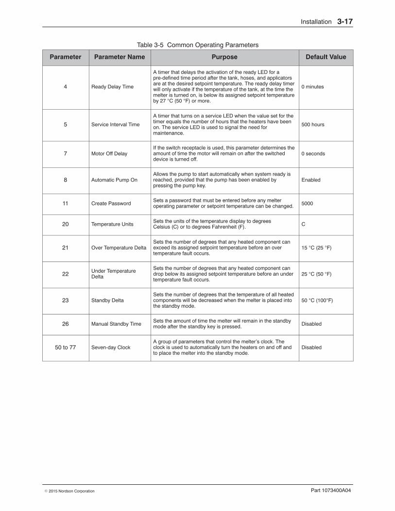
Quick Setup Table 3-5 describes the most commonly used operating parameters andtheir factory settings. Review the table to determine if the factory settings foreach parameter will support your manufacturing process. If the defaultvalues for each of these operating parameters are appropriate for yourmanufacturing process, then no melter setup is required. Go directly toSetpoint Temperature of the Tank, Hoses, and Applicators later in thissection to complete the installation process.
If you need to make changes to the factory setup or if you want to learnabout other operating parameters, go to the next part in this section,Operating Parameters.
Installation 3-17
Part 1073400A04� 2015 Nordson Corporation
Table 3-5 Common Operating Parameters
Parameter Parameter Name Purpose Default Value
4 Ready Delay Time
A timer that delays the activation of the ready LED for apre-defined time period after the tank, hoses, and applicatorsare at the desired setpoint temperature. The ready delay timerwill only activate if the temperature of the tank, at the time themelter is turned on, is below its assigned setpoint temperatureby 27 C (50 F) or more.
0 minutes
5 Service Interval Time
A timer that turns on a service LED when the value set for thetimer equals the number of hours that the heaters have beenon. The service LED is used to signal the need formaintenance.
500 hours
7 Motor Off DelayIf the switch receptacle is used, this parameter determines theamount of time the motor will remain on after the switcheddevice is turned off.
0 seconds
8 Automatic Pump OnAllows the pump to start automatically when system ready isreached, provided that the pump has been enabled bypressing the pump key.
Enabled
11 Create PasswordSets a password that must be entered before any melteroperating parameter or setpoint temperature can be changed. 5000
20 Temperature UnitsSets the units of the temperature display to degreesCelsius (C) or to degrees Fahrenheit (F). C
21 Over Temperature DeltaSets the number of degrees that any heated component canexceed its assigned setpoint temperature before an overtemperature fault occurs.
15 C (25 F)
22 Under TemperatureDelta
Sets the number of degrees that any heated component candrop below its assigned setpoint temperature before an undertemperature fault occurs.
25 C (50 F)
23 Standby DeltaSets the number of degrees that the temperature of all heatedcomponents will be decreased when the melter is placed intothe standby mode.
50 C (100F)
26 Manual Standby TimeSets the amount of time the melter will remain in the standbymode after the standby key is pressed. Disabled
50 to 77 Seven-day ClockA group of parameters that control the melter’s clock. Theclock is used to automatically turn the heaters on and off andto place the melter into the standby mode.
Disabled

Installation3-18
Part 1073400A04 � 2015 Nordson Corporation
Operating Parameters The melter uses operating parameters to store noneditable and editablevalues. Noneditable values are those that provide information about thehistorical performance of the melter. Editable values are either a numericsetpoint or a control option setting. Control option settings affect the displayof information or the function of the melter.
Operating parameters are stored in the melter’s firmware in the form of asequentially numbered list. The list is organized into the logical groupsdescribed in Table 3-6.
Table 3-6 Parameter Groups
Group ParameterNumbers Group Description
Standard0 to 8 and10 to 14 Frequently used parameters
Pressure Control 15 to 17 Configure pressure settings
Temperature Control 20 to 26 Control heater function
Input Setup 30 to 39 Configure the standard and optional inputs
Output Setup 40 to 46 Configure the standard and optional outputs
Seven-day Clock 50 to 77 Configure the clock feature
Automatic Fill Timer 78 Configure the external motor control switch
PID Selection 80 to 91 Configure the PID settings
In addition to the ability to read and edit parameter values, you can alsosave and restore the current value of every operating parameter and reviewa log of the last ten changes that were made to editable parameters.
Selecting Operating ParametersTable 3-7 provides a complete list of the operating parameters. Review thelist to determine which operating parameters would best support yourmanufacturing process. Refer to Appendix B, Operating Parameters, fordetailed information about each parameter. Appendix B contains a completedescription of each parameter, including its affect on the melter, defaultvalue, and format.
NOTE: Parameters that are used to configure optional equipment or thatare otherwise reserved in the firmware are excluded from Table 3-7.

Control switch (on/off)
Setup key
Clear/Reset key
Enter key
Installation 3-19
Part 1073400A04� 2015 Nordson Corporation
Reading or Editing Operating Parameters Regardless of whether a parameter’s value is editable or not, the procedurefor accessing each parameter in order to read or edit its current value is thesame.
To read or edit a parameter
1. Switch the melter on.
The melter performs a start-up check.
2. Press the Setup key.
The left display flashes parameter 1.
3. Use the numeric keypad to enter the number of the desired parameter.Refer to Table 3-7 for a complete list of parameters.
NOTE: If you incorrectly enter the parameter number, press theClear/Reset key to return to parameter 1 and then re-enter the correctparameter number.
When you have finished entering the one- or two-digit parameternumber, the right display indicates the parameter’s current value.
4. Do one of the following:
� If the value is noneditable, refer to Monitoring the Melter inSection 4, Operation.
� If the value is editable go to step 5.
5. Press the Enter key.
The right display flashes.
6. Use the keypad to enter the desired numeric setpoint or control optioninto the right display. Refer to Appendix B, Operating Parameters, forinformation about the numeric value or control option choices for eachparameter.
NOTE: If the keypad has no affect on the right display, the melter ispassword protected. You must enter a valid password before you canedit parameters. Refer to Entering the Melter Password in Section 4,Operation.

Installation3-20
Part 1073400A04 � 2015 Nordson Corporation
Reading or Editing Operating Parameters (contd)
To read or edit a parameter (contd)
7. Press the Enter key.
The melter checks that the new value or control option is acceptable.
� If the numeric setpoint or control option is accepted, the left and rightdisplays index to the next sequential parameter number and value.
� If the numeric setpoint or control option is not accepted, the rightdisplay will indicate dashes (----) for three seconds and then it willchange back to the original value.
8. Repeat step 5 through step 7 to read or change the next sequentialparameter number or press the Setup key to exit the setup mode.
Table 3-7 Operating Parameters
Parameter Name Range of Values Default Value
Standard
0 Enter Password 0 to 9999 4000
1 Total Hours with Heaters On (noneditable) 9999 0
2 Fault Log (noneditable) — _-F0 (empty)
3 Change History Log (noneditable) — P-_ (empty)
4 Ready Delay Time 0 to 60 minutes 0 minutes
5 Service Interval Time 0 to 8736 hours 500 hours
6 Service LED Heater Hours 0 to 9999 hours 0
7 Motor Off Delay 0 to 360 seconds 0 seconds
8 Automatic Pump On 0 (disabled) or 1 (enabled) 1 (enabled)
10 Enable or Disable Password 0 (disabled) or 1 (enabled) 0 (disabled)
11 Create Password 0 to 9999 5000
12Change Hose 1 Output to Electric ApplicatorActivation 0 (disabled) or 1 (enabled) 0 (disabled)
13Change Hose 2 Output to Electric ApplicatorActivation 0 (disabled) or 1 (enabled) 0 (disabled)
14 External Communications Lock-out 0 or 1 0 (disabled)
Temperature Control
20 Temperature Units (degrees �C or �F) C (degrees Celsius) or F (degreesFahrenheit) C (degrees Celsius)
21 Over Temperature Delta 5 �C (10 �F) to 60 �C (110 �F) 15 �C (25 �F)
22 Under Temperature Delta 5 �C (10 �F) to 60 �C (110 �F) 25 �C (50 �F)
23 Standby Delta 5 �C (10 �F) to 190 �C (350 �F) 50 �C (100 �F)
24 Automatic Standby Timeout 0 to 1440 minutes 0 (disabled)
25 Automatic Heaters Off Time 0 to 1440 minutes 0 (disabled)
26 Manual Standby Time 0 to 180 minutes 0 (disabled)
Continued...

Installation 3-21
Part 1073400A04� 2015 Nordson Corporation
Parameter Name Range of Values Default Value
Input Setup
30 Standard Input 1 0–10 and 11−14 10 (Automatic Standby)
31 Standard Input 2 0−9, 11, and 13−14 1 (Standby on/off)
32 Standard Input 3 0−9, 11, and 13−14 2 (Heaters on/off)
33 Standard Input 40−9, 11, and 13−14
4 (Hose/gun 1enable/disable)
34 Optional Input 5 0−9, 11, and 13−14 0 (disabled)
35 Optional Input 6 0−9, 11, and 13−14 0 (disabled)
36 Optional Input 7 0−9, 11, and 13−14 0 (disabled)
37 Optional Input 8 0−9, 11, and 13−14 0 (disabled)
38 Optional Input 9 0−9, 11, and 13−14 0 (disabled)
39 Optional Input 10 0−9, 11, and 13−14 0 (disabled)
Output Setup
40 Standard Output 1 0–6 1 (Ready)
41 Standard Output 2 0–6 3 (Fault)
42 Standard Output 3 0–6 4 (Not used)
43 Optional Output 4 0–6 0 (disabled)
44 Optional Output 5 0–6 0 (disabled)
45 Optional Output 6 0–6 0 (disabled)
46 Optional Output 7 0–6 0 (disabled)
Seven-day Clock
50 Current Day 1 to 7 (1 = Monday) —
51 Current Hour 0000 to 2359 —
55 Schedule 1 Heaters On 0000 to 2359 06:00
56 Schedule 1 Heaters Off 0000 to 2359 17:00
57 Schedule 1 Enter Standby 0000 to 2359 —:—
58 Schedule 1 Exit Standby 0000 to 2359 —:—
60 Schedule 2 Heaters On 0000 to 2359 —:—
61 Schedule 2 Heaters Off 0000 to 2359 —:—
62 Schedule 2 Enter Standby 0000 to 2359 —:—
63 Schedule 2 Exit Standby 0000 to 2359 —:—
65 Schedule 3 Heaters On 0000 to 2359 —:—
66 Schedule 3 Heaters Off 0000 to 2359 —:—
67 Schedule 3 Enter Standby 0000 to 2359 —:—
68 Schedule 3 Exit Standby 0000 to 2359 —:—
71 Schedule for Monday 0−7 0
72 Schedule for Tuesday 0−7 0
73 Schedule for Wednesday 0−7 0
74 Schedule for Thursday 0−7 0
75 Schedule for Friday 0−7 0
76 Schedule for Saturday 0−7 0
77 Schedule for Sunday 0−7 0
Continued...

Installation3-22
Part 1073400A04 � 2015 Nordson Corporation
Reading or Editing Operating Parameters (contd)
Table 3-7 Operating Parameters (contd)
Parameter Name Range of Values Default Value
Automatic Fill Timer
78 Automatic Fill Timer 0−99 seconds 0 (Disabled)
PID Selection
80−91 PID Selection for Hose/ApplicatorReceptacles 0−3 0 or 1
You can exit the setup mode at any time bypressing the Setup key.
Parameter numbers that are not applicableare skipped when you scroll through theoperating parameter list in the left display.
When the right display is flashing, you canquickly set the value of the current parameterto it’s lowest possible value by simultaneouslypressing both of the right-display scroll keys.
While in the setup mode, if no key is pressedfor two minutes, the melter will return to theautomatic scan mode.
You can also use the right-display scroll keysto enter or change a parameter’s value orcontrol option. After entering the parameter’snumber in the left display, press either of theright-display scroll keys to change the value orcontrol option.
Using a personal computer that is connectedto the melter through the serial port, you canview and change all of the operatingparameters from a single computer screen.
Refer to Appendix C, MelterCommunications
If password protection is enabled, the melterwill return to the password protected modewhenever you exit the setup mode.
Appendix B, parameter 10

Installation 3-23
Part 1073400A04� 2015 Nordson Corporation
This page intentionally left blank.

Installation3-24
Part 1073400A04 � 2015 Nordson Corporation
Setpoint Temperature of the Tank, Hoses, and ApplicatorsThe melter is shipped from the factory with the tank setpoint temperature at175 C (350 F) and the hose and applicator setpoint temperatures at 0degrees (turned off).
Before the melter can be used, a setpoint temperature must be assigned tothe tank, hoses, and applicators. Assign setpoint temperatures using any ofthe following methods:
� Global—The tank and all hoses and applicators are set to the samesetpoint temperature.
� Global-by-component group—All of the hoses or all of the applicatorsare set to the same setpoint temperature.
� Individual Component—The setpoint temperature of the tank and eachhose and applicator is set individually.
Since most manufacturing processes will require the tank, hoses, andapplicators to be set to the same temperature, only the global method ofassigning setpoint temperatures is described in this section. For informationabout the other two methods of assigning setpoint temperatures, refer toAdjusting Component Temperatures in Section 4, Operation.
As with operating parameters, you can also save and restore setpointtemperatures and review past changes that were made to setpointtemperatures.

Tank key
Left display andscroll key
Enter key
Ready LED
Installation 3-25
Part 1073400A04� 2015 Nordson Corporation
To assign a global setpoint temperature
1. Press and hold the Tank key for three seconds.
The left display flashes 1.
2. Scroll the left display to 0.
The right display indicates all dashes (----) and the LEDs on the tank,hose, and applicator keys turn green.
3. Press the Enter key.
The right display flashes.
4. Use the numeric keypad to enter the setpoint temperaturerecommended by the manufacturer of the hot melt.
Refer to the technical data sheet provided by the manufacturer of thehot melt to determine the optimal setpoint temperature.
5. Press the Tank key.
Each component begins to heat or cool to the new global setpointtemperature and the melter returns to the automatic scan mode.
When all of the components reach the global setpoint temperature, theready LED turns on (green).

+
Saving current settings
+
Restoring saved settings
Installation3-26
Part 1073400A04 � 2015 Nordson Corporation
Save and Restore Melter SettingsThe current value of all editable operating parameters and the setpointtemperature of each component can be saved and, if necessary, restored ata later time. When saved settings are restored, they overwrite the settingsthat are presently in use.
This save-restore feature is useful in instances where the settings that arein use are deliberately or accidentally changed and you need to return themelter to its pre-change setup.
To save current settings
With the melter in the automatic scan mode, simultaneously press thenumber 1 key and the Setup key.
S-1 appears momentarily in the right display.
To restore saved settings
CAUTION: All melter settings will be deleted! Before restoring savedsettings, ensure that use of the restored settings will not disrupt the currentprocess or create an unsafe operating condition.
With the melter in the automatic scan mode, simultaneously press thenumber 2 key and the Setup key.
S-2 appears momentarily in the right display.
If you use the restore feature before the savefeature is used for the very first time, thefactory default setpoint temperatures will berestored. This will cause the hoses andapplicators to stop heating.
You can transfer melter settings from onemelter to another using the NordsonConfiguration Manager software utility.
Refer to Appendix C, MelterCommunications

Installation 3-27
Part 1073400A04� 2015 Nordson Corporation
This page intentionally left blank.

Setup key
Left display andscroll key
Component key LEDs
Scrolling through the log
Installation3-28
Part 1073400A04 � 2015 Nordson Corporation
Review Parameter and Setpoint Temperature Changes The melter stores in a change history log, a record of the last ten changesthat were made to either operating parameters or setpoint temperatures.Since the log only stores ten changes, old log entries are overwrittenbeginning with the first log entry, by the eleventh and following log entries.
To review the change history log
1. Press the Setup key.
Operating parameter 1 flashes in the left display.
2. Press the left-display scroll key to change the display to parameter 3(the change history log).
The following occurs:
� If the last change was to an editable parameter, all of the componentkey LEDs remain off.
or
� If the last change was to a setpoint temperature, the LED on theassociated component key(s) turns on.
and
� The right display indicates the four-digit log entry associated with thelast change that was made.
Table 3-8 provides the meaning, from left to right, of each digit in thelog entry. Following the table are two example log entries.
3. Press a right-display scroll key to review each of the remaining nine logentries. Each press of a scroll key displays a progressively older logentry.
4. Press the Setup key to return to the automatic scan mode.

Installation 3-29
Part 1073400A04� 2015 Nordson Corporation
Table 3-8 Change History Log
First Digit SecondDigit Third and Fourth Digits
P (Parameter)
−
Indicates the number of the parameter that was changed
S (Setpoint)
Are used in conjunction with the LEDs on the component keys to indicate thelocation and method of a setpoint temperature change.
When this LED ison..
And the FourthDigit Indicates..
The change wasto..
And the Methodof Change was..
Tank Key 1 The tank Individual
Hose Key 1– 6 A single hose Individual
Applicator Key 1– 6A singleapplicator Individual
All Keys 0 All components Global
Hose Key 0 All hosesGlobal-by-component
Applicator Key 0 All applicatorsGlobal-by-component
Change History Log Examples
Example 1:
Parameter 4 (ready delay) was changed.
Example 2:
If the LED on the applicator key is on, then this displaywould indicate that the global-by-component method was used to changethe temperature of the applicators.
Unused log entries in the change history log areindicated by “P-_” in the right display.
To view how many heater hours have elapsedsince a specific change (displayed) was made,simultaneously press both of the right-displayscroll keys.

Opening the electrical enclosuredoor
Connector P/N 277909
Installation3-30
Part 1073400A04 � 2015 Nordson Corporation
Installing Melter Inputs DuraBlue melters are equipped with four standard inputs. Each input iscustomer-wired to the melter and then set up to provide one of the followingcontrol options:
� Place the melter into the standby mode
� Turn the heaters on and off
� Enable or disable a specific hose or applicator
� Turn the motor on and off
The inputs require a 10 to 30 VDC signal voltage. The inputs are notpolarity-sensitive.
WARNING: The operator can override the melter inputs by using thecontrol panel function keys. Ensure that the control logic for any externaldevice that sends an input signal to the melter is programmed to prevent thecreation of an unsafe condition in the event that the operator overrides anexternal input to the melter.
To wire inputs to the melter
1. Route a 2-, 4-, 6-, or 8-conductor signal cable from the controlequipment to the melter and through the PG-16 penetration on the floorof the electrical compartment. Use rigid or flexible conduit or a suitablestrain relief to protect the cable from the sharp edge of the conduitpenetration.
NOTE: Use a signal cable suitable for NEC class1 remote control andsignaling circuits. To reduce the possibility of electrical shorting, routethe cable so that it does not touch nearby circuit boards.
See Figure 3-7.
2. Connect each pair of input wires to the appropriate terminals (8 through14) on connector P/N 277909. If input number four is used, terminal 7 onconnector P/N 277908 must also be used. Both connectors are providedin the installation kit. Table 3-9 lists the terminal numbers thatcorrespond to each input.
NOTE: Connector P/N 277909 is physically keyed to prevent it frombeing used in place of connector P/N 277908, which has terminalsnumbered 1 through 7.
3. Plug the connector (P/N 277909) into the bottom receptacle of terminalXT7, which is located on the expansion board. If input number four isused, plug connector P/N 277908 into the top receptacle on terminalXT7.

Installation 3-31
Part 1073400A04� 2015 Nordson Corporation
Figure 3-7 Wiring inputs
To set up an input
Set up the parameter control option for each input that you connected to themelter. Table 3-9 lists the available control options. Refer to Setting Up theMelter earlier in this section, for information about how to select operatingparameters and edit parameter control options.
With the exception of the pumpenable/disable control option, all inputsare transition-based.
Input Setup in Appendix B
The input capacity of the melter may beincreased from four inputs to a total often inputs by adding an optional I/Oexpansion card that is available fromNordson Corporation.
Section 7, Parts

Installation3-32
Part 1073400A04 � 2015 Nordson Corporation
Installing Melter Inputs (contd)
Table 3-9 Input Data
Input Terminals Operating Parameter Control Option NoteStandard Inputs
1 8 and 9 30
0 - Input Disabled
1 - Standby On/Off
2 - Heaters On/Off
3 - Motor 1 Enable/Disable
4 - Hose/Gun 1 Enable/Disable
5 - Hose/Gun 2 Enable/Disable
6 - Hose/Gun 3 Enable/Disable
7 - Hose/Gun 4 Enable/Disable
8 - Hose/Gun 5 Enable/Disable
9 - Hose/Gun 6 Enable/Disable
10 – Automatic standby (Default)
11 - Motor 2 Enable/Disable
13 − Automatic Fill Timer No. 1
14 − Automatic Fill Timer No. 2
A
B
2 10 and 11 31
0 - Input Disabled
1 - Standby On/Off (Default)
2 - Heaters On/Off
3 - Motor Enable/Disable
4 - Hose/Gun 1 Enable/Disable
5 - Hose/Gun 2 Enable/Disable
6 - Hose/Gun 3 Enable/Disable
7 - Hose/Gun 4 Enable/Disable
8 - Hose/Gun 5 Enable/Disable
9 - Hose/Gun 6 Enable/Disable
11 - Motor 2 Enable/Disable
13 − Automatic Fill Timer No. 1
14 − Automatic Fill Timer No. 2
A
3 12 and 13 32 Same as parameter 31 (Default=2)
4 7 and 14 33 Same as parameter 31 (Default=4)
Continued...

Installation 3-33
Part 1073400A04� 2015 Nordson Corporation
Table 3-9 Input Data (contd)
Input Terminals Operating Parameter Control Option NoteOptional Inputs
5 11 and 12 34 Same as parameter 31 (Default=0) C, D
6 13 and 14 35 Same as parameter 31 (Default=0) C, D
7 15 and 16 36 Same as parameter 31 (Default=0) C, D
8 17 and 18 37 Same as parameter 31 (Default=0) C, D
9 19 and 20 38 Same as parameter 31 (Default=0) C, D
10 9 and 10 39 Same as parameter 31 (Default=0) C, D
NOTE A: If control option 3 is selected, the motor will not turn on—even if you press the pump key—if voltage is not present onthe input’s contacts.
B: If control option 10 is selected for input 1, a time must be set in parameter 24.
C: Parameters 34 through 39 are reserved for the inputs created when either the optional I/O expansion card or optionalI/O board is installed. Refer to Appendix B, Operating Parameters, for more information.
D: Refer to the instruction sheet provided with the optional I/O expansion card or analog I/O board for wiringinformation.

Opening the electrical enclosuredoor
Output connector P/N 277908
Installation3-34
Part 1073400A04 � 2015 Nordson Corporation
Installing Melter Outputs The melter is equipped with three user-configurable outputs. Outputs areused to communicate with user-supplied production equipment or controlhardware, such as a programmable logic controller.
Each output is customer-wired and then set up in the melter’s firmware toprovide one of the following outputs:
� The melter is ready
� The melter is ready and the motor is on
� A fault has occurred
� The hot melt level is low
� The service LED is on
All outputs contacts are rated at 240 VAC 2 A or 30 VDC 2 A. All contactsare normally open when the melter is turned off.
To connect an output to the melter
1. Route a 2-, 4, or 6-conductor signal cable from the control equipment tothe melter, through the PG-16 penetration on the floor of the electricalcompartment. Use rigid or flexible conduit or a suitable strain relief toprotect the cable from the sharp edge of the conduit penetration.
NOTE: Use a signal cable suitable for NEC class1 remote control andsignaling circuits. To reduce the possibility of electrical shorting, routethe cable so that it does not touch nearby circuit boards.
See Figure 3-8.
2. Connect each pair of output wires to the appropriate terminals(1 through 7) on connector P/N 277908. The connector is provided inthe installation kit. Table 3-10 lists the terminal numbers that correspondto each output.
NOTE: Terminal number 7 on connector P/N 277908 is reserved forinput number four.Connector P/N 277908 is physically keyed to preventit from being used as connector P/N 277909, which has terminalsnumbered 8 through 14.
3. Plug connector P/N 277908 into the top receptacle on terminal XT7,which is located on the expansion board.

Installation 3-35
Part 1073400A04� 2015 Nordson Corporation
Figure 3-8 Wiring outputs
To set up an output
Set up the parameter control option for each output that you connected tothe melter. Table 3-10 lists the available control options. Refer to Setting Upthe Melter earlier in this section for information about how to selectoperating parameters and edit parameter control options.
The output capacity of the melter may beincreased from three outputs to seven outputsby adding an optional I/O expansion card thatis available from Nordson Corporation.
Refer to Section 7, Parts

Installation3-36
Part 1073400A04 � 2015 Nordson Corporation
Installing Melter Outputs (contd)
Table 3-10 Output Data
Output Terminals OperatingParameter Control Options Note
Standard Outputs
1 1 and 2 40 0 - Output Disabled
1 - Ready (Default)
2 - Ready and the Motor is On
3 - Fault
4 - Tank Low Level (not available)
5 - Service LED is On
6 - Alert
A
A
B
A
A
C
2 3 and 4 41 Same as parameter 40 (Default=3)
3 5 and 6 42
Same as parameter 40 (Default=4)
Optional Outputs
4 1 and 2 43 Same as parameter 40 (Default=0)
D, E5 3 and 4 44 Same as parameter 40 (Default=0)
6 5 and 6 45 Same as parameter 40 (Default=0)
7 7 and 8 46 Same as parameter 40 (Default=0)
NOTE A: When control option condition occurs, contacts close. Contacts are normally open when power is off.
B: When control option condition occurs, contacts open. Contacts are normally open when power is off.
C: Control option 6 provides an output signal when a potential fault is detected. If control option 3 and 6 are both used,then both a fault output and an alert output signal will be present when the fault LED turns on.
D: Parameters 43 through 45 are reserved for the outputs created when either the optional I/O expansion card oroptional I/O board is installed. Refer to Appendix B, Operating Parameters, for more information.
E: For wiring information, refer to the instruction sheet that is provided with the optional I/O expansion card or analogI/O board.

Installation 3-37
Part 1073400A04� 2015 Nordson Corporation
Installing Optional Equipment Each item of optional equipment is shipped with instructions for installingand operating the equipment. Refer to Section 7, Parts, for equipment partnumbers.
Connecting a Applicator Driver, Pattern Controller,or Timer
If applicable, complete the melter installation by connecting the applicatorsto the desired applicator driver, pattern control, or timer. Refer to the productmanual provided with the device for information about installing andoperating the equipment.
Flushing the Melter WARNING: Risk of Burns! New melters contain a small quantity oflow-viscosity test fluid. Test fluid may splatter when discharged under highpressure. Before flushing the melter, ensure that the pressure control valveis set to low pressure.
Before using the melter for production, it should be flushed to remove anyresidue left over from factory-testing. Flushing the melter is accomplishedby processing a minimum of one tank volume of hot melt through the melter,hoses, and applicators.
Refer to Section 4, Operation, for information about filling the tank andoperating the melter.

Adjusting the pressure control valve
Installation3-38
Part 1073400A04 � 2015 Nordson Corporation
Adjusting the Pressure Control Valve NOTE: The pressure control valve screw is turned fully counterclockwise(at or near the valve’s lowest pressure setting) at the factory and then thelock nut is tightened.
CAUTION: Do not exceed 16 N�m (12 ft-lb) of torque when adjusting thepressure control valve.
Before placing the melter into routine operation, loosen the lock nut andadjust the pressure control valve to achieve the desired adhesive outputrate for your manufacturing process. With the melter at operatingtemperature, the line running, and the applicators dispensing adhesive, turnthe adjustment screw on the pressure control valve
� clockwise to increase the adhesive output
� counterclockwise to decrease the adhesive output
Setting Up Melter Communications You can view and change all melter settings, transfer settings betweenmelters, and upgrade or downgrade the melters operating firmware by usinga personal computer that is connected to your melter’s serial port.
Refer to Appendix C, Melter Communications, for information aboutdownloading, installing, and using the software that is required in order toconnect a personal computer to your melter.

Operation 4-1
Part 1073400A04� 2015 Nordson Corporation
Section 4Operation
WARNING: Allow only personnel with appropriate training and experienceto operate or service the equipment. The use of untrained or inexperiencedpersonnel to operate or service the equipment can result in injury, includingdeath, to themselves and others, and damage to the equipment.
This section provides information about the following operator-level tasks:
� Filling the melter tank
� Starting the melter
� Monitoring melter operation
� Adjusting the operating temperature of heated components
� Using the melter function keys
� Shutting the melter down
Most of the controls described in this section are located on thecontrol panel. Refer to Key Components in Section 2, Introduction, forthe location of the controls and indicators described in this section.
Additional Information This section presents operating procedures in their most commonly usedform. Procedural variations or special considerations are explained in theadditional information table that follows most procedures. Where applicable,some table entries also contain cross-reference information. Additionalinformation tables are indicated by the symbol shown to the left.

Component keys(tank, hose, and applicator)
Operation4-2
Part 1073400A04 � 2015 Nordson Corporation
More about Heated Components The melter contains three groups of heated components. These are thetank group, which contains the tank and the pump, the hose group, and theapplicator group. Component groups are represented on the control panelby the component keys shown to the left.
Heated components within each group are identified by their positionnumber. The position of the tank and pump is fixed at 1. Hose andapplicator position numbers are automatically assigned based on thehose/applicator receptacle they are connected to. For example, the positionnumbers of a hose/applicator pair that is connected to the secondreceptacle would be hose position 2 and applicator position 2.
The number of hose/applicator receptacles available on each melterdepends on the configuration in which the melter was ordered. DuraBluemelters may have either two or four hose/applicator receptacles.
NOTE: In some installations, auxiliary devices (such as a heated airmanifold) may be connected to a hose/applicator receptacle. In such cases,you should label (or otherwise identify) the auxiliary device as to the hose orapplicator position number that represents the device. The control panel willidentify such devices as a hose or applicator, regardless of what the deviceactually is.

Filling the tank
Operation 4-3
Part 1073400A04� 2015 Nordson Corporation
Filling the TankBefore filling the tank, confirm that the hot melt material is compatible withthe melter. Refer to Intended Use in Section 2, Introduction, for informationabout hot melt materials that should not be used in DuraBlue melters.
To fill the tank
WARNING: Hot! Risk of burns! Use a scoop to fill the tank with hot meltNever use your bare hands. Using your bare hands to fill the tank mayresult in personal injury.
1. Open the tank lid.
2. Use a scoop to fill the tank with hot melt. Table 4-1 lists the tank capacityof each DuraBlue melter.
NOTE: Nordson Corporation recommends that the tank be kept at leastone-half full while the melter is operating.
3. Close the tank lid when you are finished filling the tank.
Table 4-1 Tank Capacity
ModelCapacity*
Liters Kilograms PoundsD10 10 10 22
D16 16 16 35
*Assumes a hot melt with a specific gravity of 1

Melter control switch (on/off)
Heaters LED
Automatic scan sequence
Ready LED
Pump key
Operation4-4
Part 1073400A04 � 2015 Nordson Corporation
Starting the Melter Before starting the melter for the first time, confirm that the
� melter is fully installed including any required inputs and outputs,applicator drivers, pattern controllers, or timers.
� melter’s operating parameters are set up to support thecurrent manufacturing process.
Refer to Section 3, Installation, if any of the items listed above arenot complete.
To start the melter
1. Switch the melter on.
The melter:
� Tests the control panel LEDs
� Turns on the heaters (the heaters LED turns green)
� Begins to automatically scan through and display theactual temperature of the tank and each hose and applicator thathas a setpoint temperature that is greater than zero degrees. Thesequence of the automatic scan is: tank, each hose andapplicator pair, and then back to the tank.
� Turns on the ready LED (green) when the tank and all of thehoses and applicators are within 3 �C (5 �F) of their assignedsetpoint temperature.
2. Press the pump key to enable the pump.
� If the system has not reached the system-ready state at the time thatthe pump key is pressed, the LED on the pump key will turn yellow,indicating that the pump is enabled, but not started. The pump willstart automatically when the system-ready state is reached.
� If the system has reached the system-ready state at the time that thepump key is pressed, the pump will start and the LED on the pumpkey will turn green, indicating that the pump is running.
� If the melter is set up for manual pump activation, the pump LED willnot turn on and the pump will not start until the pump is manuallystarted using the switching device.
NOTE: You can change the way the pump key operates by changingparameter 8 (automatic pump on). Refer to Appendix B, OperatingParameters.

Operation 4-5
Part 1073400A04� 2015 Nordson Corporation
If the melter is switched on whenthe temperature of the tank is 27 �C (50 �F)or greater below its assignedsetpoint temperature (cold start condition), theready LED will not turn on until the readydelay (defined when the melter was setup) has elapsed.
Appendix B, parameter 4
The time remaining on the ready delay (inminutes) appears in the right display at theend of every scan cycle. When only oneminute remains in the ready delay time, theright display counts down in seconds.
Appendix B, parameter 4
You can by-pass the ready delay time bypressing the Heaters key twice.
The appearance of F4 in the rightdisplay immediately after the melter isswitched on indicates a problem with themelter’s processor or main board.
Section 4, Monitor Melter Faults
The appearance of F1 in the rightdisplay immediately after starting themelter indicates that a hose or applicatorcordset may be loose or disconnected.
Section 6, Troubleshooting
If the melter is set up for manual pumpactivation and parameter 7 (motor off delay)has been changed from the default, the pumpwill not stop until a user-specified amount oftime has elapsed.
Appendix B, parameter 7
The condition of one or more inputs,may prevent the heaters from turning on.
Installing Melter Inputs in Section 3,Installation
If the seven-day clock feature was set up andturned on when the melter was last switchedoff, the clock will automatically turn on the nexttime the melter is switched on.
Section 4, Using Melter FunctionKeys
If a power failure occurs, the melter will restartin it’s normal heat-up cycle, even if the heaterswere off or the melter was in standby prior tothe power failure. If the seven-day clock wason prior to the power failure, the melter willrestart in the mode dictated by the clockschedule at the time the melter restarts.

Ready LED
Operation4-6
Part 1073400A04 � 2015 Nordson Corporation
Monitoring the Melter The melter provides indicators that allow you to:
� Quickly confirm that the melter is operating correctly
� Monitor the actual temperature of the tank group and each hoseand applicator
� Identify melter faults
� Determine when service is required
The melter automatically determines the number and location of allhoses and applicators that are connected to it. Refer to More AboutHeated Components, earlier in this section, for information abouthose/applicator capacity and the identification of heated components.
You can also use a personal computer to monitor the melter. Refer toAppendix C, Melter Communications, for information about connecting apersonal computer to the melter and installing the required software.
Confirm that the Melter is Operating Correctly The ready LED turns on (green) when all of the heated componentsare within 3 �C (5 �F) of their setpoint temperature.
The ready LED will not turn on, or will turn off, if any of the following eventsoccur:
� The ready delay is still counting down.
� The operator or a remote input places the melter in the standbymode.
� The seven-day clock places the melter in the standby mode.
� There is a fault (the fault LED will turn on).
Refer to Monitoring Melter Faults and Using Melter Function Keys laterin this section for information about melter faults and using the seven-dayclock and standby functions. Refer to Appendix B, parameter 4, forinformation about the ready delay.

LEDs on component keys
Operation 4-7
Part 1073400A04� 2015 Nordson Corporation
Heated components with asetpoint temperature of zero degrees areskipped during the automatic scan cycle.
The setpoint temperature of the tank andthe pump cannot be set independently.
The time remaining on the ready delayappears in the right display at the end of eachscan cycle.
Appendix B, parameter 4
You can override the seven-day clock atany time. If the clock has turned the heatersoff, pressing the heaters key will turnthe heaters back on. If the clock has placedthe melter into the standby mode, pressingthe standby key will return theheated components to their assigned setpointtemperature.
Section 4, Using Melter FunctionKeys
Monitor Component Temperatures You can check the actual temperature of each heated component—the tankand each hose and applicator—using the automatic scan mode or bymanually selecting and checking each component.
By default, the melter remains in the automatic scan mode except when:
� The melter is placed into the setup mode
� The setpoint temperature of all hoses and applicators is set to zerodegrees
� A fault occurs
To check component temperatures using the automatic scan mode
1. When the ready LED is on, observe the LEDs on the component keys.
2. When the LED on the key that represents the desired componentgroup (tank, hose, or applicator) turns on, observe the left display until itindicates the position number of the specific component you want tocheck.
3. When the position number of the desired component appears in theleft display, observe the right display to determine the component’sactual temperature.

Left display andscroll key
Component temperature display
Operation4-8
Part 1073400A04 � 2015 Nordson Corporation
Monitor Component Temperatures (contd)
To manually check a component’s temperature
1. Press the key (tank, hose, or applicator) that represents the componentgroup you want to check.
The automatic scan stops and the left display indicates the numberof the first sequential component in the selected component group. Theright display indicates the component’s actual temperature.
NOTE: When the tank key is pressed, the left display does notindicate a component number (blank display).
2. If the first sequential component is not the component you wantto check, use the left-display scroll key to change to the correctcomponent number.
The right display indicates the actual temperature of theselected component.
3. Press the Setup key twice to return to the automatic scan mode.
When you scroll the left display pastthe number of the last sequential componentin a component group, the number of thefirst sequential component in the nextcomponent group appears in the left display.
The melter will return to the automaticscan mode two minutes after the last keyis pressed.
When you press the Tank key, it is the pumptemperature that is actually indicated in theright display. To check the actual temperatureof the tank, simultaneously press the Tankkey and the left-display scroll key.
The default unit for temperature displayis degrees Celsius (C). This may bechanged to degrees Fahrenheit usingoperating parameter 20.
Appendix B, Parameter 20
The LEDs on each component key will changefrom green to yellow if any component in thecomponent group drops more than 3 �C (5 �F)below its assigned setpoint temperature.
You can check the setpoint temperature of acomponent at any time, by pressing theright-display UP scroll key. Holding down thescroll key while the melter is in the automaticscan mode reveals the setpoint of eachcomponent that is scanned.

Operation 4-9
Part 1073400A04� 2015 Nordson Corporation
This page intentionally left blank.

Operation4-10
Part 1073400A04 � 2015 Nordson Corporation
Monitor Melter Faults The melter alerts the operator to the faults listed in Table 4-2. Faults affectthe melter in one of three ways: the heaters turn off; the heaters remain on,but the fault condition persists; or the melter stops functioning.
When a fault occurs, you must diagnose and correct the fault condition andthen place the melter back into operation. You can use the fault log todetermine the type, order, and relative time of the last ten faults.
Table 4-2 Melter Faults
DisplayCode/Sub-code Name Affect on Melter Cause Corrective Action
F1/None RTD Heaters turn off
The RTD for thecomponent indicatedhas failed or thecomponent wasdisconnected fromthe melter.
Replace RTD
Check hose/applicatorconnections
See flowchart T.2
F2/NoneUndertemperature Heaters turn off
The actual temperatureof the componentindicated has droppedbelow the undertemperature delta,which was set usingparameter 22.
Check for conditionsthat may cause a dropin ambient temperature
Raise the setpointtemperature of thecomponent
Replace RTD
See flowchart T.2
F3/None Over temperature Heaters turn off
The actual temperatureof the componentindicated has increasedbeyond the overtemperature delta,which was set usingparameter 21.
Replace RTD
See flowchart T.2
F4/1 RAM testMelter stopsfunctioning
Internal RAM failure Replace CPU
F4/2Internal Clocktime
Heaters remain on,but fault conditionpersists
Internal clock failure Replace CPU
F4/4Internal clockbattery backedRAM
Heaters remain on,but fault conditionpersists
Battery-backed RAMfailure
Replace CPU
F4/5Internal clockbattery
Heaters remain on,but fault conditionpersists
Battery-backed RAMbattery dead
Replace CPU
Continued...

Operation 4-11
Part 1073400A04� 2015 Nordson Corporation
Table 4-2 Melter Faults (contd)
DisplayCode/Sub-code Name Affect on Melter Cause Corrective Action
F4/6 Analog-to-digitalMelter stopsfunctioning
RTD analog-to-digitalconverter failed
Replace main board orCPU
F4/7Analog-to-digitalcalibration
Melter stopsfunctioning
Failed hose orapplicator
RTD analog-to-digitalconverter could not becalibrated
Replace hose orapplicator. Note: Setsetpoint to zero to avoidF1 fault.
Replace main board orribbon cable, or CPU
F4/8Main boardfeedback
Melter stopsfunctioning
Communication failurebetween main boardand CPU
Replace main board,ribbon cable, or CPU
F4/A ThermostatMelter stopsfunctioning
Tank or manifoldthermostat is open
Replace thermostat,XP6 harness, or mainboard
F4/CExpansion boardconnection
Melter stopsfunctioning
Ribbon cableP/N 1026662 is notconnected at J1 on themain board and/or at J2on the expansion board
Check the ribbon cableconnections and makeconnections asapplicable.
F4/dCommunicationswith optional I/Ocard
Heaters remain on,but fault conditionpersists
Communication failurebetween CPU and theoptional I/O card
Replace the I/O card orCPU
F4/EFieldbuscommunicationsfailure
Alert output (ifoutput option 6 isselected)Melter continues tooperate normally.
Fieldbus card failure. Replace the Fieldbuscard

Fault LED (red)
Operation4-12
Part 1073400A04 � 2015 Nordson Corporation
How F1, F2, and F3 Faults are Handled
When the melter detects an F1, F2, or an F3 fault:
1. The automatic scan stops and the melter begins to monitor the potentialfault for up to two minutes. The ready and heater LEDs remain on duringthe two-minute time period. If, at any time during the two-minute period,the melter detects that the fault condition no longer exists, the melter willreturn to the automatic scan mode.
2. The LED on the affected component key (tank, hose, or applicator) turnson to indicate the type of component that has, or is, failing.
3. The right display indicates the type of fault (F1, F2, or F3).
4. The left display indicates, as follows, the component that has, or is,failing.
� If the LED on the tank key is on, the left display will indicate either 1for the tank or 2 for the pump.
� If the LED on the hose or applicator key is on, the left display willindicate the number of the affected hose or applicator.
5. If the fault condition still exists at the end of the two-minute monitoringperiod, the ready LED will turn off, the red fault LED will turn on, theheaters turn off, and the melter records the fault in the fault log. Refer toTo review the fault log later in this section.

Operation 4-13
Part 1073400A04� 2015 Nordson Corporation
How F4 Faults are Handled When the melter detects an F4 fault:
1. The ready LED turns off and the red fault LED turns on.
2. All of the component key LEDs (tank, hose, and applicator) turn off.
3. The right display indicates F4.
4. The left display indicates a sub-code. Sub-codes classify the fault asbeing fatal or nonfatal. The affect on the melter of each of these twoclasses of F4 faults is:
Fatal—The fault LED turns on and stays on and the melter stopsfunctioning completely.
Nonfatal—The fault LED turns on for five seconds, but the heaters andpump continue to operate normally. Nonfatal faults affect the internalclock and the optional I/Os.
Refer to Section 6, Troubleshooting, for information about diagnosing F4faults.
5. The melter records the fault in the fault log. Refer to To review the faultlog later in this section.

Clear/Reset key
Heater key
Operation4-14
Part 1073400A04 � 2015 Nordson Corporation
Monitor Melter Faults (contd)
To put the melter back into operation
1. Diagnose and correct the fault condition. Refer to Section 6,Troubleshooting, for information about diagnosing and correcting faultconditions.
NOTE: When a fatal F4 fault exists, the control switch will not function.Remove power to the melter at the local disconnect switch.
2. Return the melter to the automatic scan mode by pressing the Setupkey twice.
3. Press the Clear/Reset key.
4. Press the Heater key to turn on the heaters.
To view the temperature of a heated componentwhen an F2 or F3 fault exists, simultaneouslypress and hold both of the right-display scrollkeys.
You can temporarily dismiss an F1 fault (RTD)and return to the automatic scan mode bypressing the Clear/Reset key. The heaters will,however, remain off. If the fault condition stillexists two minutes after pressing the clear/resetkey, the fault LED will turn back on.
When an F1 fault code appears, youcan determine whether the fault was causedby an open or a shorted RTD bysimultaneously pressing both of the right-displayscroll keys. If the right display indicates OP,the RTD is open, if it indicates SH, the RTDhas shorted.
If, for any reason, a component reaches235 �C (458 �F), an immediate F3 fault will occur(no two-minute monitoring period).
If F4 appears in the right display when you pressthe clock key, the internal clock function hasfailed.

Operation 4-15
Part 1073400A04� 2015 Nordson Corporation
This page intentionally left blank.

Setup Key
Left display and scroll key
Scrolling through the fault log
Operation4-16
Part 1073400A04 � 2015 Nordson Corporation
Monitor Melter Faults (contd)
To review the fault log
1. Press and hold the Setup key.
The automatic scan stops and operating parameter 1 appears in theleft display.
2. Scroll the left display to parameter 2 (the fault log).
The right display indicates the last fault that occurred as follows:
� If the last fault was an F1, F2, or F3 fault, then the LED onthe affected component key turns yellow.
� If the last fault to occur was an F4 fault, then the LEDs on all ofthe component keys turn off.
� The right display indicates the log entry for the last fault tooccur. Table 4-3 provides the meaning of each digit in the logentry. Following the table are two example fault log entries.
3. Press the right-display scroll key to review each of the remainingnine log entries. Each press of the scroll key displays a progressivelyolder log entry.
NOTE: The fault log only stores the last ten faults. After ten faultsoccur, the existing log entries are overwritten, beginning with the oldestentry, by the eleventh and following log entries.
4. Press the Setup key to return to the automatic scan mode.
Table 4-3 Fault Log
First Digit Second and Third Digits Fourth Digit
Component:
- FType of fault:
1 = Tank or hose/gun 1 0 = Unused log entry
2 = Pump or hose/gun 2 1 = RTD (open or short)
3 = Hose 3 or gun 3 2 = Component under temperature
4 = Hose 4 or gun 4 3 = Component over temperature
5 = Hose 5 or gun 5 4 = Processor or electrical failure
6 = Hose 6 or gun 6

Operation 4-17
Part 1073400A04� 2015 Nordson Corporation
Fault Log Examples
Example 1:
An unused log entry.
Example 2:
If the LED on the tank key were on, this log entrywould indicate that the tank is under temperature. If the LED on the hosekey were on, this log entry would indicate that hose 1 is under temperature.
To view the number of heater hours that haveelapsed since a log entry was created,simultaneously press both of the right-displayscroll keys. The hours are indicated in the rightdisplay.
The melter will return to the automaticscan mode if the fault log is left open for a periodof two minutes without any key being pressed.
When an F1 fault is the result of ahose/applicator pair being disconnected from themelter, two fault log entries are created. The firstentry is for the applicator and the second entry isfor the hose.

Service LED (yellow)
Clear/Reset key
Operation4-18
Part 1073400A04 � 2015 Nordson Corporation
Monitor the Service Interval The melter can be set up so that the service LED located on the left sideof the control panel turns on after a customer-defined time period haselapsed. The service LED may be used to signal the need to change thehot melt filter or to complete any other customer-specified maintenanceactivity. Once the specified maintenance is performed, the service LED mustbe reset.
To reset the service LED
With the melter in the scan mode, press the Clear/Reset key to turn off theservice LED and reset the service interval time.
The default setting for the service interval timeis 500 hours.
Appendix B, parameter 5

Operation 4-19
Part 1073400A04� 2015 Nordson Corporation
This page intentionally left blank.

Tank key
Left display andscroll key
Enter key
Ready LED
Operation4-20
Part 1073400A04 � 2015 Nordson Corporation
Adjusting Component Temperatures You can adjust the setpoint temperature of heated components using thefollowing methods:
� Global—The tank and all hoses and applicators are set to the samesetpoint temperature.
� Global-by-component group—All of the hoses or all of theapplicators are set to the same setpoint temperature.
� Individual Component—The setpoint temperature of the tankand each hose and applicator is adjusted independently.
Before adjusting setpoint temperatures, confirm that each hose/applicatorpair is connected to the correct hose/applicator receptacle. For example,hose/applicator pair 1 should be connected to the receptacle 1. Refer toMore About Heated Components earlier in this section for information abouthose/applicator positions.
To adjust setpoint temperatures using the global method
1. Press and hold the Tank key for three seconds.
The left display flashes 1.
2. Scroll the left display to 0 (flashing).
The right display indicates all dashes (----) and the LEDs on all ofthe component keys turn green.
3. Press the Enter key.
The right display flashes.
4. Use the keypad to enter the setpoint temperature recommended bythe manufacturer of the hot melt. Refer to the technical datasheet provided by the manufacturer of the hot melt to determine theoptimal setpoint temperature.
NOTE: If the keypad or the right-display scroll keys have no affecton the right display, the melter is password protected. You must entera valid password before you can change setpoint temperatures. ReferEnter the Melter Password, later in this section.
5. Press the Tank key.
All components begin to heat or cool to the new globalsetpoint temperature. When all of the components reach theirsetpoint temperature, the ready LED turns on (green).

Tank, hose, and applicator keys
Operation 4-21
Part 1073400A04� 2015 Nordson Corporation
To adjust the setpoint temperature using the global-by-componentmethod
1. Press and hold the Hose or Applicator key for three seconds.
The left display indicates the number of the first sequential hose orapplicator. The right display indicates the current setpoint temperature ofthe hose or the applicator.
2. Scroll the left display to 0.
The right display indicates all dashes (- - - -).
3. Press the Enter key.
The right display flashes.
4. Use the keypad to enter the setpoint temperature recommended bythe manufacturer of the hot melt. Refer to the technical datasheet provided by the manufacturer of the hot melt to determine theoptimal setpoint temperature.
NOTE: If the keypad or the right-display scroll keys have no affecton the right display, the melter is password protected. You must entera valid password before you can change setpoint temperatures. Refer toEntering the Melter Password later in this section.
5. Press the Enter key.
The hoses or the applicators begin to heat or cool to their newsetpoint temperature.

Operation4-22
Part 1073400A04 � 2015 Nordson Corporation
Adjusting Component Temperatures (contd)
To adjust the setpoint temperature of an individual component
1. Press and hold the Tank, Hose, or Applicator key for three seconds.
If the tank key was pressed, the left display indicates 1 (Flashing). If ahose or applicator key was pressed, the left display indicates thenumber of the first sequential hose or applicator (Flashing). The rightdisplay indicates the current setpoint temperature of the componentindicated in the left display.
2. Scroll the left display to the number of the desired component.
The right display indicates the current setpoint temperature of thecomponent that you selected in the left display.
3. Press the Enter key.
The right display flashes.
4. Use the keypad to enter the setpoint temperature recommended bythe manufacturer of the hot melt. Refer to the technical datasheet provided by the manufacturer of the hot melt to determine theoptimal setpoint temperature.
NOTE: If the keypad or the right-display scroll keys have no affecton the right display, the melter is password protected. You must entera valid password before you can change setpoint temperatures. Refer toEntering the Melter Password later in this section.
5. Do one of the following:
� To register the new setpoint temperature and then move on tochange the setpoint temperature of the next sequential component,press the Enter key and then repeat steps 4 and 5.
� To register the new setpoint temperature and return to the automaticscan mode, go to step 6.
6. Press any component key (tank, hose, or applicator).
The selected component begins to heat or cool to its newsetpoint temperature.

Operation 4-23
Part 1073400A04� 2015 Nordson Corporation
If you enter a valid setpoint temperature for ahose/applicator that is not connected to the melter orif you enter a setpoint temperature that is out ofrange, the right display will indicate dashes (----) forthree seconds and then change back to the originalsetpoint temperature.
When the right display is flashing, you can quicklychange the current setpoint temperature to 0degrees (off) by simultaneously pressing both ofright-display scroll keys.
After removing a hose or a applicator, usethe individual component method of setpointtemperature adjustment to set the component’stemperature to zero degrees (off). This willavoid causing an F1 fault when a hose or applicatoris added, use the individual component method to setthe desired temperature.
The factory setpoint temperature of the tank is 175�C (350 �F). The factory setpoint temperature of allothers components is zero degrees (off).
When the units of temperature is set to degreesCelsius, the minimum and maximum setpointtemperatures are 40 �C and 230 �C. When the unitsof temperature are set to degrees Fahrenheit, theminimum and maximum setpoint temperatures are100 �F and 450 �F.
When using the right-display scroll keys to adjust asetpoint temperature, the right displayautomatically increments between 0, 175, and 230�C or between 0, 350, and 450 �F.
If you make a mistake while you are changing asetpoint temperature, but you have not yet pressedthe enter key, press the Clear/Reset key to reset theright display to the original temperature.
The melter will exit the setup mode and return to theautomatic scan mode two minutes after the last keyis pressed.
A global setpoint temperature of zero degrees(Celsius or Fahrenheit) turns all components off.
When scrolling through component numbers in theleft display, component numbers that are associatedwith unused hose/applicator receptacles are skipped.
The melter stores a record of the last ten changesmade to the setpoint temperatures (and operatingparameters) in the change history log.
Refer to Section 3, Installation,Review Parameter and setpointTemperature Changes
You can save setpoint temperature changes bysimultaneously pressing the 1 key and the Setupkey.
Refer to Section 3, Installation, Saveand Restore Melter Settings

Operation4-24
Part 1073400A04 � 2015 Nordson Corporation
Entering the Melter Password If the melter is password protected, a valid password must beentered before any setpoint temperature or melter parameter can bechanged.
To enter a melter password
1. Press the Setup key.
The left display indicates parameter 0 (flashing) and the rightdisplay indicates 4000.
2. Press the Enter key.
The right display begins flashing.
3. Use the keypad to enter the melter password.
4. Press the Enter key.
One of the following occurs:
� If the password is correct, the left display indicates parameter 1.
� If the password is incorrect, the left display remains at 0 and theright display momentarily indicates dashes (----) and then returns to4000.
If the password is incorrect, re-enter it and then press the Enter key.
The melter will automatically revert back to thepassword-protected mode two minutes afterthe last key press (any key). To force themelter back into the password protected modebefore two minutes has elapsed, press theSetup key twice.
The melter password is created andenabled/disabled during system setup.
Setting Up the Melter in Section 3,Installation

Operation 4-25
Part 1073400A04� 2015 Nordson Corporation
This page intentionally left blank.

Heater key
Pump key
Operation4-26
Part 1073400A04 � 2015 Nordson Corporation
Using Melter Function Keys The control panel provides the following standard and special function keys:
Standard function keys
� Heater
� Pump
� Setup
Special function keys
� Seven-day clock
� Standby
CAUTION: Unintentionally activating function keys can, under thecorrect circumstances, have undesirable effects on the melter or themanufacturing process. Only personnel who are familiar with the melter’ssetup and its connection with the manufacturing process should use thefunction keys. Improper use of the function keys can result in erratic processbehavior or personal injury.
Heater Key Use the heater key to manually turn the component heaters on andoff. Pressing the heater key overrides the control (on or off) of the heatersby either the seven-day clock feature or a remote input. The LED on theheater key illuminates when the heaters are on.
When a fault occurs (refer to Monitoring Melter Faults earlier in thissection) the heaters automatically turn off. The heater key is used to turn theheaters back on after correcting a fault condition.
Pump Key Use the pump key to enable, start, and stop the pump. The LED on thepump key is yellow when the pump is enabled (not running) and is greenwhen the pump is running.
If the automatic pump on feature (parameter 8) is disabled, then thepump key must be used to start the pump when the melter is ready.
If any of the inputs are set up to use the pump enable/disable control option,the pump motor will not start until the pump is enabled and the correctvoltage is applied to the input contacts. If the pump is enabled, but the inputvoltage is not present, the pump LED will flash green.

Setup key
Seven-day clock key
Operation 4-27
Part 1073400A04� 2015 Nordson Corporation
Setup Key Use the setup key to place the melter into and take the melter out ofthe setup mode. When the melter is placed into the setup mode, theautomatic scan stops and the left and right displays are used to select andread or edit operating parameters.
Seven-day Clock Key Use the seven-day clock key to turn the melter’s clock feature on and off.When the clock is on, the temperature of each heated component isautomatically regulated based on a set of user-defined schedules.
To accommodate daily shift work and non-working days, fourclock schedules are available. Schedules 1, 2, and 3 are used to specifywhen the heaters should turn on and off or when the melter should enterand exit the standby mode. Schedule 0 is used to keep the melter in the lastcondition dictated by the clock (heaters on or off, or standby).
When a clock schedule calls for the heaters to be on, the heatersare regulated at their pre-assigned setpoint temperatures. When theclock activates the standby mode, the setpoint temperature of eachcomponent is temporarily reduced by a pre-set standby delta.
Refer to Appendix B, Operating Parameters, Seven-day Clock, forinformation about setting up the seven-day clock and the standby delta.
If the melter is switched off while the clock is on,the clock will automatically turn back on the nexttime the melter is switched back on.
If the heaters are manually turned off at the timethat a clock schedule calls for the heaters to beon, the heaters will not turn back on until the nextclock schedule calls for them to be on.
The clock will still operate when the melteris faulting or is in the setup mode.
If F4 appears in the right display when you pressthe clock key, the internal clock function hasfailed.
Section 7, Troubleshooting

Standby key
Operation4-28
Part 1073400A04 � 2015 Nordson Corporation
Using Melter Function Keys (contd)
Standby Key Use the standby key to manually place the melter into, and take it out of, thestandby mode. Using the standby mode during periods of time whenthe melter is inactive helps conserve energy and allows heated componentsto quickly return to their setpoint temperatures when the melter is onceagain needed.
When the melter is placed into the standby mode, the temperatures ofall components are reduced down from their setpoint temperature by apre-set standby delta. The melter will remain in the standby mode until thestandby key is pressed or the function of one of the operating parameterstakes the melter out of the standby mode.
If the melter was set up to use the manual standby timer(parameter 26), pressing the standby key will place the melter in thestandby mode for the period of time specified by the timer. After the manualstandby time has elapsed, the melter will once again begin heating all of thecomponents to their assigned setpoint temperature.
Using the standby key overrides the control of the melter (on or off) bythe seven-day clock or a remote input.
Refer to Section 3, Installation, Setting Up the Melter, and to Appendix B,Operating Parameters, for information about setting the standby delta andthe standby timer.
The melter may also be set up to automaticallyenter the standby mode using a variety ofoperating parameters.
Appendix B, Parameters 25, 26, 57,30–33, 62, and 67
Whenever manual standby is enabled, thestandby LED blinks.
Appendix B, Parameter 26

Melter control switch (on/off)
Operation 4-29
Part 1073400A04� 2015 Nordson Corporation
Shutting Down the Melter Shut the melter down when it will not be used for an extended period oftime.
To shut the melter down
1. Switch the melter off.
2. Disable the applicators as follows:
� Air-operated applicators: Turn off the air supply to the applicators.
� Electric applicators: Turn off the applicator driver, pattern controller,or timer.

Operation4-30
Part 1073400A04 � 2015 Nordson Corporation

Maintenance 5-1
Part 1073400A04� 2015 Nordson Corporation
Section 5Maintenance
WARNING: Allow only personnel with appropriate training and experienceto operate or service the equipment. The use of untrained or inexperiencedpersonnel to operate or service the equipment can result in injury, includingdeath, to themselves and others, and damage to the equipment.
Table 5-1 describes the preventive maintenance tasks required to keepDuraBlue melters operating within their specified limits and to preventequipment malfunctions. For information about maintaining optionalequipment that was supplied by Nordson, refer to the instructions providedwith the equipment.
If the melter stops operating or is operating incorrectly, refer to Section 6,Troubleshooting, for information about diagnosing common problems andperforming corrective maintenance.
Table 5-1 Preventive Maintenance Tasks
Task Frequency Reference
Relieving system pressure Before performing any maintenancetask that requires opening ahydraulic connection or port
Relieving System Pressure
Cleaning the exterior of the melter,hoses, and applicators
Daily Cleaning the Melter
Replacing the filter � As needed
� When changing the type or grade of
hot melt
Replacing the Filter
Instruction sheet provided withreplacement filter
Cleaning the tank � When changing the type or grade ofhot melt
� When excessive charring occurs
Cleaning the Tank

Pump key
Maintenance5-2
Part 1073400A04 � 2015 Nordson Corporation
Relieving System Pressure Before disconnecting any hydraulic fitting or opening any pressurized port,always complete the following procedure to safely relieve hydraulic pressurethat may be trapped inside the melter, hoses, and applicators.
To relieve system pressure
1. Press the Pump key to stop the pump.
2. Trigger the applicators until hot melt no longer flows from theapplicators.
Locking Out External Communications WARNING: Disable external inputs and fieldbus communcations with themelter before performing maintenance. Failure to disable external inputs orfieldbus communications with the melter can result in personal injury due tounexpected operation of the melter while performing maintenance.
To lockout external communications with the melter
� Set the control option for operating parameter 14 to 1 (enabled).
Refer to Section 3, Setting Up the Melter, for information about changingoperating parameters.

Maintenance 5-3
Part 1073400A04� 2015 Nordson Corporation
This page intentionally left blank.

Maintenance5-4
Part 1073400A04 � 2015 Nordson Corporation
Cleaning the Melter To prevent components from overheating due to heat build-up or loss of aircirculation, regularly remove any hot melt that collects on the exterior of themelter, hoses, and applicators.
If hot melt inadvertently spills inside the melter’s interior spaces, the sidepanels can be removed in order to clean out the spilled hot melt.
WARNING: Risk of electricution and fire! Do not clean the melter with adirect stream of water or steam. Use only water or an appropriate,non-flammable cleaning solution that is applied using a clean cloth.Cleaning the melter using a direct stream of water or steam or a flammablesolvent can result in property damage and personal injury, including death.
To clean the exterior of the melter
� Use only cleaning compounds that are compatible with polyester.
� Apply cleaning compounds using a soft cloth.
� Do not use pointed or sharp tools to clean the exterior surface.
To remove and replace the exterior panels
See Figure 5-1.
1. De-energize the melter. Refer to Section 1, Safety.
2. Use a 4 mm (5/32-inch) hex-head wrench to turn the 1/2-turn fastenerlocated in the center of each side panel counterclockwise.
3. Lift the panel out of the melter’s frame.
4. Reverse steps 2 and 3 to reinstall each panel.

Maintenance 5-5
Part 1073400A04� 2015 Nordson Corporation
Figure 5-1 Removing the exterior panels

Hot melt flow path
Maintenance5-6
Part 1073400A04 � 2015 Nordson Corporation
Replacing the Filter Some DuraBlue melters are equipped with a 100-mesh (0.15-mm)disposable hot melt filter. The filter removes debris and char from the hotmelt as it flows from the tank. Hot melt flows from the inside to the outsideof the filter, trapping contaminants inside the filter. There is no need toback-flush or clean the filter.
When the filter reaches the end of its service life, it should be replaced. Thefactors that determine the service life of the filter are:
� the type, grade, and purity of the solid-form hot melt
� the set point temperature of the tank
� the period of time that the hot melt remains in the tank
The filter should also be replaced when making the change to a differenttype or grade of hot melt.
To determine the optimal service life for the filter, monitor and compare thetotal number of hours that the heaters are on with observations of:
� the purity of the dispensed hot melt
� increases in operating pressure
� the frequency of applicator nozzle replacement or cleaning
As an aid to ensuring that the filter is replaced at the end of its service life,the melter is equipped with a service LED that turns on at the end of acustomer-defined time period. Refer to Setting Up the Melter in Section 3,Installation, for information about the service interval time.

Pump key
Loosening the filter
Maintenance 5-7
Part 1073400A04� 2015 Nordson Corporation
To replace the filter
1. Relieve the system pressure. Refer to Relieving System Pressure at thebeginning of this section.
2. Use an 8 mm (5/16-inch) hex-head wrench or an adjustable wrench toloosen (counterclockwise) and then remove the filter.
3. Properly dispose of the old filter.
4. Confirm that the O-ring on the new filter is in good condition (100-meshfilter is P/N 1028305).
NOTE: 50- and 150-mesh filters are also available (P/Ns 1021941 and1034720).
5. Screw the filter into the pump body and then tighten the filter to4.5 Nm (40 in.-lb).
6. Resume normal operation.

Pump key
Maintenance5-8
Part 1073400A04 � 2015 Nordson Corporation
Cleaning the Tank To avoid the problems that can occur when different hot melt materials aremixed or when hot melt char forms in the tank, clean the tank when:
� changing to a different type of hot melt
� excessive char builds up inside the tank
NOTE: The tank cleaning procedures provided in this section require thatan appropriate flushing material be used. The flushing material should becompatible with both the previous adhesive and the new adhesive, ifapplicable.
To clean the tank when changing hot melt
1. Operate the melter normally until the tank is empty.
2. Press the Pump key to stop the pump.
3. Allow the melter to heat or cool to the temperature recommended by themanufacturer of the flushing material.
4. While wearing the appropriate protective equipment, wipe any residualhot melt from the inside of the tank.
5. Add the appropriate type and quantity of flushing material to the tank.
6. Press the Pump key to start the pump.
7. Pump all of the flushing material from the tank and through the hosesand applicators.
8. Return the melter to normal operation and pump a minimum of one tankvolume of fresh hot melt through the tank, hoses, and applicators.

Pump key
Tank strainer
Closing the pressure control valve
Maintenance 5-9
Part 1073400A04� 2015 Nordson Corporation
To clean the tank of excessive char
1. Remove the old hot melt and loose char as follows:
a. Operate the melter normally until the tank is empty.
b. Press the Pump key to stop the pump.
c. Allow the melter to heat or cool to the temperature recommended bythe manufacturer of the flushing material.
d. While wearing the appropriate protective equipment, wipe anyresidual hot melt and loose char from the inside of the tank.
e. Remove the tank strainer, clean it with an appropriate flushingmaterial, and then reinstall it.
2. Add the appropriate type and quantity of hot melt solvent to the tank.
3. Disconnect a hose from a applicator and direct the hose into a wastecontainer.
4. Close the pressure control valve by turning the valve all the wayclockwise.
WARNING: Risk of burns! Wear protective equipment and use cautionwhen pumping hot material into a waste container.
5. Press the Pump key to start the pump.
6. When the tank is empty, stop the pump.
7. Fill the tank with fresh hot melt.
8. Repeat steps 5 and 6 to pump all of the hot melt out of the tank.
9. Reconnect the disconnected hose to its applicator.
10. Replace the filter. Refer to Replacing the Filter earlier in this section.
11. Fill the tank with fresh hot melt and then purge all of the hoses andapplicators with the fresh hot melt.
12. Restore the system to normal operation.

Maintenance5-10
Part 1073400A04 � 2015 Nordson Corporation

Troubleshooting 6-1
Part 1073400A04� 2015 Nordson Corporation
Section 6Troubleshooting
WARNING: Allow only personnel with appropriate training and experienceto operate or service the equipment. The use of untrained or inexperiencedpersonnel to operate or service the equipment can result in injury, includingdeath, to themselves and others, and damage to the equipment.
This section provides quick-reference information for diagnosing melterfaults and pump operating variables as well as comprehensive melterdiagnostic information that is provided in flowchart format.
If you cannot resolve the problem using the troubleshooting flowchart,contact your Nordson representative for technical assistance.
Safety� Never disconnect cables from, or reconnect cables to, any circuit board
while the melter is energized.
� Before breaking any hydraulic connection, always relieve systempressure. Refer to Relieving System Pressure in Section 5,Maintenance.
� Refer to the safety information provided with optional equipment.

Troubleshooting6-2
Part 1073400A04 � 2015 Nordson Corporation
Melter Faults Table 6-1 lists the four types of melter faults, potential causes, and expectedcorrective actions.
Table 6-1 Melter Faults
DisplayCode/Sub-code Name Affect on Melter Cause Corrective Action
F1/None RTD Heaters turn off
The RTD for thecomponent indicatedhas failed or thecomponent wasdisconnected fromthe melter.
Replace RTD
Check hose/applicatorconnections
See flowchart T.2
F2/NoneUndertemperature Heaters turn off
The actual temperatureof the componentindicated has droppedbelow the undertemperature delta,which was set usingparameter 22.
Check for conditionsthat may cause a dropin ambient temperature
Raise the setpointtemperature of thecomponent
Replace RTD
See flowchart T.2
F3/None Over temperature Heaters turn off
The actual temperatureof the componentindicated has increasedbeyond the overtemperature delta,which was set usingparameter 21.
Replace RTD
See flowchart T.2
F4/1 RAM testMelter stopsfunctioning
Internal RAM failure Replace CPU
F4/2Internal Clocktime
Heaters remain on,but fault conditionpersists
Internal clock failure Replace CPU
F4/4Internal clockbattery backedRAM
Heaters remain on,but fault conditionpersists
Battery-backed RAMfailure
Replace CPU
F4/5Internal clockbattery
Heaters remain on,but fault conditionpersists
Battery-backed RAMbattery dead
Replace CPU
Continued...

Troubleshooting 6-3
Part 1073400A04� 2015 Nordson Corporation
Table 6-1 Melter Faults (contd)
DisplayCode/Sub-code Name Affect on Melter Cause Corrective Action
F4/6 Analog-to-digitalMelter stopsfunctioning
RTD analog-to-digitalconverter failed
Replace main board orCPU
F4/7Analog-to-digitalcalibration
Melter stopsfunctioning
Failed hose orapplicator
RTD analog-to-digitalconverter could not becalibrated
Replace hose orapplicator. Note: Setsetpoint to zero to avoidF1 fault.
Replace main board orribbon cable, or CPU
F4/8Main boardfeedback
Melter stopsfunctioning
Communication failurebetween main boardand CPU
Replace main board,ribbon cable, or CPU
F4/A ThermostatMelter stopsfunctioning
Tank or manifoldthermostat is open
Replace thermostat,XP6 harness, or mainboard
F4/CExpansion boardconnection
Melter stopsfunctioning
Ribbon cableP/N 1026662 is notconnected at J1 on themain board and/or at J2on the expansion board
Check the ribbon cableconnections and makeconnections asapplicable.
F4/dCommunicationswith optional I/Ocard
Heaters remain on,but fault conditionpersists
Communication failurebetween CPU and theoptional I/O card
Replace the I/O card orCPU
F4/EFieldbuscommunicationsfailure
Alert output (ifoutput option 6 isselected)Melter continues tooperate normally.
Fieldbus card failure. Replace the Fieldbuscard

Troubleshooting6-4
Part 1073400A04 � 2015 Nordson Corporation
Pump Operating Variables When diagnosing apparent melter malfunctions, it is helpful to understandthe following variables that control the status of the pump—enabled,disabled, running—and the associated indication that is provided by thepump LED.
� Use/activation of a remote input to control the motor
� Use of parameter 8, Automatic Pump On
� Ready status of the melter
� Activation of a switched input (hand-held applicator or footswitch)
� Activation of the pump key
Table 6-2 provides the status of the pump LED for each combination of thepump operating variables.
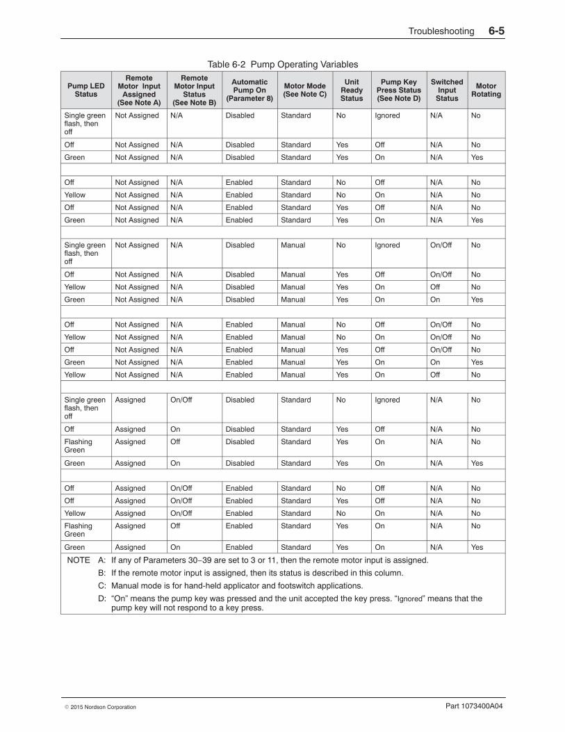
Troubleshooting 6-5
Part 1073400A04� 2015 Nordson Corporation
Table 6-2 Pump Operating Variables
Pump LEDStatus
RemoteMotor Input
Assigned(See Note A)
RemoteMotor Input
Status(See Note B)
AutomaticPump On
(Parameter 8)
Motor Mode(See Note C)
UnitReadyStatus
Pump KeyPress Status(See Note D)
SwitchedInput
Status
MotorRotating
Single greenflash, thenoff
Not Assigned N/A Disabled Standard No Ignored N/A No
Off Not Assigned N/A Disabled Standard Yes Off N/A No
Green Not Assigned N/A Disabled Standard Yes On N/A Yes
Off Not Assigned N/A Enabled Standard No Off N/A No
Yellow Not Assigned N/A Enabled Standard No On N/A No
Off Not Assigned N/A Enabled Standard Yes Off N/A No
Green Not Assigned N/A Enabled Standard Yes On N/A Yes
Single greenflash, thenoff
Not Assigned N/A Disabled Manual No Ignored On/Off No
Off Not Assigned N/A Disabled Manual Yes Off On/Off No
Yellow Not Assigned N/A Disabled Manual Yes On Off No
Green Not Assigned N/A Disabled Manual Yes On On Yes
Off Not Assigned N/A Enabled Manual No Off On/Off No
Yellow Not Assigned N/A Enabled Manual No On On/Off No
Off Not Assigned N/A Enabled Manual Yes Off On/Off No
Green Not Assigned N/A Enabled Manual Yes On On Yes
Yellow Not Assigned N/A Enabled Manual Yes On Off No
Single greenflash, thenoff
Assigned On/Off Disabled Standard No Ignored N/A No
Off Assigned On Disabled Standard Yes Off N/A No
FlashingGreen
Assigned Off Disabled Standard Yes On N/A No
Green Assigned On Disabled Standard Yes On N/A Yes
Off Assigned On/Off Enabled Standard No Off N/A No
Off Assigned On/Off Enabled Standard Yes Off N/A No
Yellow Assigned On/Off Enabled Standard No On N/A No
FlashingGreen
Assigned Off Enabled Standard Yes On N/A No
Green Assigned On Enabled Standard Yes On N/A Yes
NOTE A: If any of Parameters 30−39 are set to 3 or 11, then the remote motor input is assigned.
B: If the remote motor input is assigned, then its status is described in this column.
C: Manual mode is for hand-held applicator and footswitch applications.
D: “On” means the pump key was pressed and the unit accepted the key press. “Ignored” means that thepump key will not respond to a key press.

a
b
Troubleshooting question and actionblocks
a) Question b) Action
Troubleshooting6-6
Part 1073400A04 � 2015 Nordson Corporation
Using the Troubleshooting Flow Chart The flowchart, which is provided at the end of this section, is designed toassist you in diagnosing and correcting a complete or partial stop in hot meltoutput from the applicators. The chart is organized in a simplequestion-action block format. If your response to a question is yes (Y),continue downward in the chart to the next question or action block. If youresponse is no (N), continue to the right to the next question or action block.All diagnostic paths within the chart end with an action block that specifiesone of the following three courses of action:
� Refer to information provided elsewhere in this manual
� Replace a component
� Complete a diagnostic procedure (DP.x)
To return your melter to service as quickly as possible, the chart is designedunder the assumption that it is preferable to immediately replace a faultyassembly as opposed to conducting detailed diagnostics and repair of theassembly while the melter is out of service.
Use of the chart assumes that the melter is installed correctly and that it isset up to support the current manufacturing process. Refer to Section 3,Installation, for information about installing and setting up the melter.
Troubleshooting Quick-checksBefore using the troubleshooting charts confirm:
� whether or not service was recently performed on the melter or themelter’s settings were recently adjusted.
� the correct voltage plug is installed on terminal J1. Refer to Section 3,Installation, for information about selecting the correct voltage plug.
� external inputs (if used) are functioning properly.
� the standby or clock functions are not turned on (if not required orexpected at the current time).

Troubleshooting 6-7
Part 1073400A04� 2015 Nordson Corporation
Returning the Melter Setup to Factory Settings By returning the melter to its factory setting many common melter problemscan be isolated to either a problem with the melter settings or the melterhardware.
To return the melter to its factory settings, simultaneously press and holdthe Setup key and the right-display DOWN arrow key, and then, whileholding down these keys, cycle the melter control switch off and on. Whenthe melter restarts, release the two keys.
Identifying Electrical Components Tables 6-3 through 6-6 provide detailed descriptions of the circuit boardindicators, connection points, and test points that are referred to in thetroubleshooting chart. Figure 6-1 illustrates the location of each of thesecircuit board components.
Table 6-3 Main Board Components
Item Number Type DescriptionIndicators
DS2 Neon Power to tank heater
DS3 Neon Power to pump heater
DS4 Neon Power to 5 VDC and 24 VDC power supplies
DS5 Neon Power to hose/gun 1 heaters
DS6 Neon Power to hose/gun 2 heaters
DS7 Neon Power to motor
DS8 LED Control signal for hose 1 heater
DS9 LED Control signal for applicator 1 heater
DS10 LED Control signal for tank heaters
DS11 LED Control signal for motor
DS12 LED Control signal for applicator 2 heater
DS13 LED Control signal for hose 2 heater
DS14 LED Control signal for pump heater
DS15 LED +5 VDC control voltage present
DS17 LED Trigger closure present at XP3 or XP4
Fuses
F1/F2 −− Tank heaters (10 A, 250 V, fast-acting)
F3/F4 −− 5 VDC and 24 VDC power supplies (2A, 250 V, slow-blow)
F5/F6 −− Pump heater (5 A, 250 V, fast-acting, 5 x 20 mm)
F7/F8 −− Hose/gun 1 heaters (6.3 A, 250 V, 5 x 20 mm)
F9/F10 −− Hose/gun 2 heaters (6.3 A, 250 V, 5 x 20 mm)
F11/F12 −− Motor power (6.3 A, 250 V, 5 x 20 mm)
Continued...

Troubleshooting6-8
Part 1073400A04 � 2015 Nordson Corporation
Identifying Electrical Components (contd)
Table 6-3 Main Board Components (contd)
Item Number Type DescriptionConnection Points
XT1 Input High-voltage power connection to board
J1 Input/output Signal ribbon cable between main board and CPU
XP1 Output Control voltage to applicator solenoid 1
XP2 Output Control voltage to applicator solenoid 2
XP3 Input Switch closure from hand-held applicator 1
XP4 Input Switch closure from hand-held applicator 2
XP5 Output Control voltage to pump RTD
XP6 Output Control voltage to tank RTD and tank overtemperature thermostat
X1 Output High-voltage to pump heater
X2 Output High-voltage to tank heaters
X3 Output High-voltage to motor
X4 Output High-voltage and control voltage out to hose/gun 1
X5 Output High-voltage and control voltage out to hose/gun 2
X6 Output 24 VDC to expansion board
X7 Input Unit on/off control switch
Test Points
TP7 Contact +5 VDC control voltage present
TP2 Contact Circuit common of low-voltage power supply
Table 6-4 Expansion Board Components
Item Number Type DescriptionIndicators
DS1 LED 24 VDC present at X3
Connection Points
XT1 Output AC power into board
XT2 Output AC power out to power module (Hose/Guns 3 and 4)
XT3 Input AC power out to main board
XT7 Output/Input Positions 1–6 are control outputs; Positions 7–14 are control inputs
X1/X2 Jumper Input voltage configuration plugs
X3 Input 24 VDC in from main board
X4 Input/output Ribbon cable connection between expansion board and power module(Hose/gun 3 and 4)
J2 Input/output Ribbon cable connection between expansion board and main board

Troubleshooting 6-9
Part 1073400A04� 2015 Nordson Corporation
Table 6-5 Power Module Components
Item Number Type DescriptionIndicators
N1 Neon Hose 4 is turned on
N2 Neon Applicator 4 is turned on
N3 Neon Hose 3 is turned on
N4 Neon Applicator 3 is turned on
Connection Points
J1 Input/output Ribbon cable connection between power module and expansion board
J2 Input/output Connection point for the wire harness between hose/gun 4 and the powermodule
J3 Input/output Connection point for the wire harness between hose/gun 3 and the powermodule
J4/J5 Input AC power input from XT2 on the expansion board
Fuses
F1, F2 −− Hose 4 and applicator 4
F3, F4 −− Hose 3 and applicator 3

Troubleshooting6-10
Part 1073400A04 � 2015 Nordson Corporation
Identifying Electrical Components (contd)
Table 6-6 Part Numbers of Cable and Boards in Figure 6-1
Identifier Component Connection One Connection Two Part NumberB1 Expansion board Not applicable Not applicable 1031201
B2 Main board Not applicable Not applicable 1097997
B3 Power module Not applicable Not applicable 1031202
B4 CPU board Not applicable Not applicable 1028325
C1 Cable Tank heaters X2 (TANK CONN) onmain board
See Note A
C2 Cable Tank thermostat and RTD XP6 (TANK RTD) onmain board
1031234
C3 Cable Pump RTD XP5 (PUMP RTD) onmain board
1031233
C4 Cable Pump heater X1 (PUMP CONN) onmain board
See Note A
C5 Cable Motor bulkheadconnector
X3 (MOTOR CONN) onmain board
1055958 (240V)
NOTE: The motor cable is included with the motorassembly and is not available separately.
C6 Cable XT2 on expansion board J4/J5 on power modules 1027340
C7 Cable XT3 on expansion board XT1 on main board 1027341
C8 Cable X3 (24V SUPPLY) onexpansion board
X6 on main board 1027342
C9 Cable XP1 or XP2 on mainboard
Applicator solenoid 1 or 2 1045269
C10 Cable X4 or X5 (HOSE/GUN)on main board
Hose/gun 1 and 2receptacles on backpanel
1024925 (240V)
Cable J3 or J2 (HOSE/GUN) onpower module
Hose/gun 3 and 4receptacles on backpanel
1024925 (240V)
C11 Cable X7 (PWR SWITCHINPUT) on main board
Control switch onelectrical cabinet door
1026663
C12 Cable XP3 or XP4 (HANDGUNTRIG INPUT) on mainboard
Switch receptacles onback panel
1025746
RC1 Ribbon cable X4 on expansion board J1 on power module 189211
RC2 Ribbon cable J1 on CPU board J1 on main board and J2on expansion board
1026662
RC3 Ribbon cable J3 on CPU board RS232 connector onelectrical cabinet door
1029938
NOTE A: Refer to Heaters in Section 7, Parts, for heater kit part numbers.

Troubleshooting 6-11
Part 1073400A04� 2015 Nordson Corporation
Exp
ansi
on
Bo
ard
(B
1)
C6
RC
1
RC
2
C1
C2
C3 C4
C5
C7
C8
C9
C9
C10
C10
Mai
n B
oar
d (
B2)
C11
C12
C12
C10
C10
RC
3
CP
U B
oar
d (
B4)
Po
wer
Mo
du
le (
B3)
Bac
k P
anel
Co
ntr
ol S
wit
ch
Fig
ure
6-1
Loca
tion
of e
lect
rical
com
pone
nts
(ref
er to
Tab
le 6
-6 fo
r pa
rt n
umbe
rs)

Troubleshooting6-12
Part 1073400A04 � 2015 Nordson Corporation
Thi
s pa
ge in
tent
iona
lly le
ft bl
ank.

Troubleshooting 6-13
Part 1073400A04� 2015 Nordson Corporation
+
−
No
ad
hes
ive
ou
tpu
t fr
om
on
e o
r m
ore
ap
plic
ato
rs
Go
toT.
3
+
−
+
−
Do
dash
es a
ppea
r in
bot
hth
e le
ft an
d rig
ht d
ispl
ay?
Turn
the
cont
rol s
witc
h on
.D
oes
the
mel
ter
star
t?
Sto
p.
+
−
Upl
oad
new
sof
twar
e.
Ref
er to
App
endi
x C
.
+
−
Do
the
wor
ds U
P L
OA
Dap
pear
acr
oss
the
disp
lays
?
Is th
e w
ire h
arne
ss th
at is
conn
ecte
d to
term
inal
X7
on th
e m
ain
boar
d lo
ose?
Turn
the
cont
rol s
witc
h of
f,se
cure
the
harn
ess
tote
rmin
al X
7, a
nd th
en tu
rnth
e co
ntro
l sw
itch
back
on
+
−
Is th
e fa
ult L
ED
illum
inat
ed?
Rep
lace
the
cont
rol s
witc
h.
P/N
101
7947
.
Has
glu
e ou
tput
sto
pped
from
all
appl
icat
ors?
+
−
Is th
e re
ady
LED
illum
inat
ed?
+
−
Is th
e co
ntro
l pan
elill
umin
ated
?G
o to
T.1
Go
toT.
5
Go
toT.
4
Du
raB
lue
Tro
ub
lesh
oo
tin
gC
har
ts
Sta
rt
Go
toT.
2

Troubleshooting6-14
Part 1073400A04 � 2015 Nordson Corporation

Troubleshooting 6-15
Part 1073400A04� 2015 Nordson Corporation
Con
trol
pan
el is
not
illu
min
ated
T.1
+
−
+
−
Is th
ere
pow
er a
t ter
min
albl
ock
XT
1 on
the
expa
nsio
n bo
ard?
See
Fig
ure
6-1.+
−
Is th
e po
wer
dis
conn
ect
switc
h th
at is
ser
ving
the
mel
ter
turn
ed o
n?
Is th
e co
rrec
t vol
tage
plu
gse
cure
ly a
ttach
ed to
conn
ecto
rs X
1/X
2 on
the
mai
n bo
ard?
Ref
er to
Tabl
e 3-
4, S
ectio
n3,
Inst
alla
tion.
+
−
Is th
ere
pow
er a
t ter
min
alX
T1
on th
e m
ain
boar
d?
Che
ck th
e pl
ant w
iring
betw
een
the
disc
onne
ctsw
itch
and
the
mel
ter.
Turn
the
disc
onne
ct s
witc
hon
.
Rep
lace
/sec
ure
the
volta
ge p
lug.
Che
ck th
e w
ire h
arne
ssbe
twee
n co
nnec
tor
XT
3 on
the
expa
nsio
n bo
ard
and
term
inal
blo
ck X
T1
on th
em
ain
boar
d.
See
Fig
ure
6-1.
+
−
Hav
e fu
ses
F3/
F4
on th
em
ain
boar
d bl
own?
See
Fig
ure
6-1.
Rep
lace
bot
h fu
se F
3 an
dfu
se F
4.
P/N
103
1203
Rep
lace
the
mai
n bo
ard.
P/N
109
7997
+
−
Is th
e po
wer
on
the
plan
tsi
de o
f the
dis
conn
ect
switc
h th
at is
ser
ving
the
mel
ter?
Che
ck/r
epai
r th
e pl
ant
wiri
ng.
Go
to T
.1.1
+
−
Is in
dica
tor
DS
4 on
the
mai
n bo
ard
illum
inat
ed?
See
Fig
ure
6-1.

Troubleshooting6-16
Part 1073400A04 � 2015 Nordson Corporation

Troubleshooting 6-17
Part 1073400A04� 2015 Nordson Corporation
T.1.
1
+
−
+
−
Is th
e gr
een
pow
er L
ED
on
the
CP
U b
oard
illum
inat
ed?
See
Fig
ure
6-1.+
−
Is th
e vo
ltage
acr
oss
TP
7(+
) an
d T
P2
(−)
on th
em
ain
boar
d be
twee
n 4.
75an
d 5.
25 V
DC
?
See
Fig
ure
6-1.
Is th
e vo
ltage
acr
oss
TP
2(+
) an
d T
P4
(−)
on th
eC
PU
boa
rd b
etw
een
4.75
and
5.25
VD
C?
See
Fig
ure
6-1. +
−
Is th
e re
d C
PU
faul
t LE
Dill
umin
ated
?
See
Fig
ure
6-1.
Rep
lace
the
mai
n bo
ard.
P/N
109
7997
Che
ck th
e rib
bon
cabl
e or
repl
ace
the
CP
U b
oard
.
CP
U -
P/N
102
8325
Rep
lace
the
CP
U b
oard
.
P/N
102
8325
+
−
+
−
Doe
s ch
angi
ng th
e m
ain
boar
d co
rrec
t the
pro
blem
?
P/N
109
7997
Sec
ure
or r
epla
ce th
eca
ble.
P/N
102
6662
Is th
e rib
bon
cabl
ebe
twee
n th
e m
ain
boar
dan
d th
e C
PU
boa
rd lo
ose
or v
isib
ly d
amag
ed?
See
Fig
ure
6-1.
Sec
ure
or r
epla
ce th
eca
ble.
P/N
102
6662
+
−
Con
tact
Nor
dson
for
tech
nica
l ass
ista
nce.
Rep
lace
the
CP
U b
oard
.
P/N
103
1179
Doe
s ch
angi
ng th
e C
PU
boar
d co
rrec
t the
pro
blem
?
P/N
102
8325
Sto
p.
+
−
Is L
ED
DS
15 o
n th
e m
ain
boar
d ill
umin
ated
?
See
Fig
ure
6-1.
Rep
lace
the
mai
n bo
ard.
P/N
109
7997
+
−
Is th
e rib
bon
cabl
ebe
twee
n th
e m
ain
boar
dan
d th
e C
PU
boa
rd lo
ose
or v
isib
ly d
amag
ed?
See
Fig
ure
6-1.
Con
trol
pan
el is
not
illum
inat
ed >
Dis
conn
ect s
witc
h is
on
>
DS
4 is
illu
min
ated

Troubleshooting6-18
Part 1073400A04 � 2015 Nordson Corporation

Troubleshooting 6-19
Part 1073400A04� 2015 Nordson Corporation
Fau
lt LE
D is
illu
min
ated
T.2
?
+
−
Is th
e ta
nk k
ey L
ED
illum
inat
ed?
Con
firm
that
the
RT
D h
asfa
iled.
+
−
Go
toT.
2.1
+
−
Are
all
of th
eap
plic
ator
-to-
hose
and
hose
-to-
mel
ter
elec
tric
alco
rdse
ts s
ecur
ely
conn
ecte
d?
Doe
s th
e fa
ult r
eocc
ur if
you
mov
e th
e fa
ultin
gho
se/a
pplic
ator
pai
r to
akn
own
good
hose
/app
licat
or c
onne
ctor
?
Rep
lace
the
hose
or
repl
ace
the
appl
icat
orR
TD
.
Ref
er to
the
hose
or
appl
icat
or m
anua
l.
Go
toT.
2.2
Sec
ure
the
elec
tric
alco
nnec
tors
and
then
pre
ssth
e re
set k
ey.
Con
tact
Nor
dson
for
tech
nica
l ass
ista
nce.
Rec
ord
the
faul
t cod
esin
dica
ted
in b
oth
the
left
and
right
dis
play
s an
d th
enco
ntac
t Nor
dson
for
tech
nica
l ass
ista
nce.
+
−
Is a
n F
1 (R
TD
) fa
ult
indi
cate
d in
the
right
disp
lay?
+
−
Is a
n F
2(u
nder
tem
pera
ture
) fa
ult
indi
cate
d in
the
right
disp
lay?
+
−
Is a
n F
3 (o
vert
empe
ratu
re)
faul
t ind
icat
ed in
the
right
disp
lay?
+
Is a
n F
4 fa
ult i
ndic
ated
inth
e rig
ht d
ispl
ay?

Troubleshooting6-20
Part 1073400A04 � 2015 Nordson Corporation
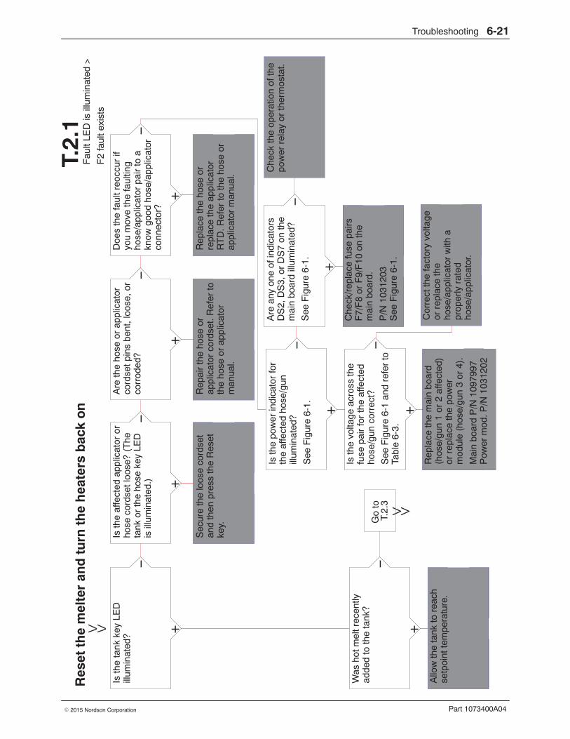
Troubleshooting 6-21
Part 1073400A04� 2015 Nordson Corporation
+
−
+
−
Res
et t
he
mel
ter
and
tu
rn t
he
hea
ters
bac
k o
n
Fau
lt LE
D is
illu
min
ated
>
F2
faul
t exi
sts
T.2.
1
Go
toT.
2.3
Was
hot
mel
t rec
ently
adde
d to
the
tank
?
? Allo
w th
e ta
nk to
rea
chse
tpoi
nt te
mpe
ratu
re.
Sec
ure
the
loos
e co
rdse
tan
d th
en p
ress
the
Res
etke
y.
+
−
Rep
air
the
hose
or
appl
icat
or c
ords
et. R
efer
toth
e ho
se o
r ap
plic
ator
man
ual.
Is th
e po
wer
indi
cato
r fo
rth
e af
fect
ed h
ose/
gun
illum
inat
ed?
See
Fig
ure
6-1. +
Rep
lace
the
mai
n bo
ard
(hos
e/gu
n 1
or 2
affe
cted
)or
rep
lace
the
pow
erm
odul
e (h
ose/
gun
3 or
4).
Mai
n bo
ard
P/N
109
7997
Pow
er m
od. P
/N 1
0312
02
+
−
Is th
e vo
ltage
acr
oss
the
fuse
pai
r fo
r th
e af
fect
edho
se/g
un c
orre
ct?
See
Fig
ure
6-1
and
refe
r to
Tabl
e 6-
3.
Rep
lace
the
hose
or
repl
ace
the
appl
icat
orR
TD
. Ref
er to
the
hose
or
appl
icat
or m
anua
l.
Cor
rect
the
fact
ory
volta
geor
rep
lace
the
hose
/app
licat
or w
ith a
prop
erly
rat
edho
se/a
pplic
ator
.
+
−
Are
any
one
of i
ndic
ator
sD
S2,
DS
3, o
r D
S7
on th
em
ain
boar
d ill
umin
ated
?
See
Fig
ure
6-1.
Che
ck/r
epla
ce fu
se p
airs
F7/
F8
or F
9/F
10 o
n th
em
ain
boar
d.
P/N
103
1203
See
Fig
ure
6-1.
+
−
Is th
e ta
nk k
ey L
ED
illum
inat
ed?
+
−
Is th
e af
fect
ed a
pplic
ator
or
hose
cor
dset
loos
e? (
The
tank
or
the
hose
key
LE
Dis
illu
min
ated
.)
+
−
Are
the
hose
or
appl
icat
orco
rdse
t pin
s be
nt, l
oose
, or
corr
oded
?
Doe
s th
e fa
ult r
eocc
ur if
you
mov
e th
e fa
ultin
gho
se/a
pplic
ator
pai
r to
akn
ow g
ood
hose
/app
licat
orco
nnec
tor?
Che
ck th
e op
erat
ion
of th
epo
wer
rel
ay o
r th
erm
osta
t.

Troubleshooting6-22
Part 1073400A04 � 2015 Nordson Corporation

Troubleshooting 6-23
Part 1073400A04� 2015 Nordson Corporation
+
−
Res
et t
he
mel
ter
and
tu
rn t
he
hea
ters
bac
k o
n
Fau
lt LE
D is
illu
min
ated
>
F3
faul
t exi
sts
T.2.
2
Is th
ere
a D
C d
rive
near
the
mel
ter?
? Sto
p.
+
−
Doe
s in
stal
ling
an R
Csn
ubbe
r on
the
DC
driv
ean
d re
setti
ng th
e m
elte
rcl
ear
the
faul
t?
P/N
332
182
Sto
p.
+
−
Doe
s el
ectr
ical
ly g
roun
ding
the
mel
ter’s
cha
ssis
to th
epa
rent
mac
hine
/sup
port
and
then
res
ettin
g th
em
elte
r cl
ear
the
faul
t?
Cor
rect
the
setp
oint
tem
pera
ture
of t
heco
mpo
nent
or
incr
ease
the
over
tem
pera
ture
set
poin
t.
Inst
all a
n R
C s
nubb
er o
nth
e m
elte
r.
P/N
332
182
+
−
Is th
e ta
nk/p
ump
TR
IAC
oper
atin
g pr
oper
ly?
Rep
lace
the
grid
or
rese
rvoi
r R
TD
.
P/N
103
1234
Rep
lace
the
mai
n bo
ard.
P/N
109
7997
Go
toT.
2.4
+
−
Is m
ore
than
one
com
pone
nt o
verh
eatin
g?(C
heck
the
actu
alte
mpe
ratu
re o
f the
faul
ting
com
pone
nt.)
+
−
Is th
e ta
nk L
ED
illum
inat
ed?
+
−
Was
the
setp
oint
tem
pera
ture
of t
he fa
ultin
gho
se/a
pplic
ator
just
redu
ced?

Troubleshooting6-24
Part 1073400A04 � 2015 Nordson Corporation

Troubleshooting 6-25
Part 1073400A04� 2015 Nordson Corporation
+
−
Fau
lt LE
D is
illu
min
ated
>
F2
faul
t exi
sts
>
Tank
key
LE
D is
illu
min
ated
>
No
hot m
elt w
as r
ecen
tly a
dded
to th
eta
nkT.2.
3?
+
−
Is th
e re
sist
ance
cor
rect
for
the
tank
hea
ters
(2)
and
the
pum
p he
ater
(1)
?R
efer
to H
eate
rS
peci
ficat
ions
in S
ectio
n 8
for
resi
stan
ce v
alue
s.
+
−
Is th
e vo
ltage
acr
oss
the
dow
nstr
eam
sid
e of
fuse
sF
1 an
d F
2 on
the
mai
nbo
ard
180−
265
VA
C?
See
Fig
ure
6-1.
Are
the
tank
and
pum
pT
RIA
CS
func
tioni
ngpr
oper
ly?
?C
onta
ct N
ords
on fo
rte
chni
cal a
ssis
tanc
e.
+
−
Are
the
tank
and
man
ifold
RT
Ds
func
tioni
ngpr
oper
ly?
Rep
lace
the
tank
or
the
pum
p he
ater
.
Ref
er to
Sec
tion
7, P
arts
.
Che
ck/c
orre
ct h
ouse
volta
ge.
Rep
lace
the
mai
n bo
ard.
P/N
109
7997
Rep
lace
the
mal
func
tioni
ng R
TD
.
Tank
- P
/N 1
0312
34P
ump
- P
/N 1
0312
33
Sto
p.
+
−
Doe
s re
plac
ing
fuse
s F
1an
d F
2 on
the
mai
n bo
ard
and
then
res
ettin
g th
em
elte
r cl
ear
the
faul
t?
P/N
102
8329
Rep
lace
the
mai
n bo
ard.
P/N
109
7997
+
−
Are
any
of t
he in
dica
tors
DS
2, D
S3,
or
DS
7 on
the
mai
n bo
ard
illum
inat
ed?
See
Fig
ure
6-1.
+
−
Is th
e po
wer
indi
cato
r fo
rth
e af
fect
ed h
ose/
gun
illum
inat
ed?
See
Fig
ure
6-1.
Che
ck th
e op
erat
ion
of th
epo
wer
rel
ay o
r th
eth
erm
osta
t.

Troubleshooting6-26
Part 1073400A04 � 2015 Nordson Corporation

Troubleshooting 6-27
Part 1073400A04� 2015 Nordson Corporation
Fau
lt LE
D is
illu
min
ated
>
An
F3
faul
t exi
sts
on a
hos
e or
ap
plic
ator
>
The
set
poin
t tem
pera
ture
was
not
chan
ged
T.2.
4
Sto
p.R
epla
ce th
e m
ain
boar
d.
P/N
109
7997
+
−
Doe
s re
plac
ing
the
mai
nbo
ard
and
rese
tting
the
mel
ter
clea
r th
e fa
ult
Rep
lace
the
CP
U b
oard
.
P/N
103
1179
+
−
Doe
s th
e fa
ult c
lear
if y
ousw
itch
the
faul
ting
hose
/gun
pai
r to
a k
now
ngo
od h
ose/
gun
conn
ecto
ran
d th
en r
eset
the
mel
ter?
+
−
Doe
s th
e fa
ult c
lear
if y
oure
plac
e ju
st th
e ho
se o
rju
st th
e ap
plic
ator
RT
Dan
d th
en r
eset
the
mel
ter?
+
−
Hav
e LE
Ds
DS
8/D
S9
orD
S12
/DS
13 o
n th
e m
ain
boar
d st
oppe
d fla
shin
g?
See
Fig
ure
6-1.
Sto
p.
Rep
lace
the
mai
n bo
ard
(hos
e/gu
n 1
or 2
affe
cted
)or
rep
lace
the
pow
erm
odul
e (h
ose/
gun
3 or
4).
Mai
n bo
ard
P/N
109
7997
Pow
er m
od. P
/N 1
0312
02

Troubleshooting6-28
Part 1073400A04 � 2015 Nordson Corporation

Troubleshooting 6-29
Part 1073400A04� 2015 Nordson Corporation
+
−
No
faul
ts >
Rea
dy L
ED
is n
ot il
lum
inat
ed
T.3
Doe
s th
e rig
ht d
ispl
ayin
dica
te th
at c
ompo
nent
sar
e st
ill h
eatin
g up
?
? Wai
t for
all
com
pone
nts
tore
ach
setp
oint
tem
pera
ture
.
+
−
Wai
t the
the
inpu
t to
initi
ate
the
heat
ers
or u
se th
eH
eate
rs k
ey to
man
ually
turn
the
heat
ers
on.
Is th
e re
ady
dela
y co
untin
gdo
wn?
Wai
t for
the
read
y de
lay
toco
unt d
own.
Ref
er to
App
endi
x B
,pa
ram
eter
4.
+
−
The
cur
rent
clo
ck s
ched
ule
has
the
heat
ers
turn
ed o
ff.
Is th
e st
andb
y LE
D o
n?
The
mel
ter
is in
the
stan
dby
mod
e.
Ref
er to
Sta
ndby
Key
inS
ectio
n 4,
Ope
ratio
n.
Con
tact
Nor
dson
for
tech
nica
l ass
ista
nce.
+
−
Is th
e H
eate
rs k
ey L
ED
illum
inat
ed?
+
−
Is a
rem
ote
inpu
t bei
ngus
ed to
con
trol
the
heat
ers?
+
−
Is th
e cl
ock
LED
on?
Pre
ss th
e H
eate
rs k
ey to
turn
the
heat
ers
on.
?
+
−
Rep
lace
the
tank
or
the
pum
p he
ater
.
Ref
er to
Sec
tion
7, P
arts
.
Is th
e re
sist
ance
cor
rect
for
the
tank
hea
ters
(2)
and
the
pum
p he
ater
(1)
?R
efer
to H
eate
rS
peci
ficat
ions
in S
ectio
n 8
for
resi
stan
ce v
alue
s.

Troubleshooting6-30
Part 1073400A04 � 2015 Nordson Corporation

Troubleshooting 6-31
Part 1073400A04� 2015 Nordson Corporation
No
faul
ts >
Rea
dy L
ED
is il
lum
inat
ed >
No
hot m
elt o
utpu
t fro
m a
ll ap
plic
ator
s
T.4
Go
toT.
4.2
The
mel
ter
is w
aitin
g fo
r an
exte
rnal
inpu
t bef
ore
the
mot
or w
ill s
tart
.
Sto
p.
+
−
Doe
s th
e m
otor
sta
rt if
you
activ
ate
the
appl
icat
ortr
igge
r or
foot
sw
itch?
+
−
Is th
e se
tpoi
nt te
mpe
ratu
reof
the
tank
bel
ow th
ete
mpe
ratu
rere
com
men
ded
by th
em
anuf
actu
rer
of th
e ho
tm
elt?
+
−
Is th
e ap
plic
ator
trig
ger
cord
set o
r fo
ot s
witc
hpr
oper
ly c
onne
cted
to th
eba
ck o
f the
mel
ter.
Ref
er to
Con
nect
ing
Hos
es a
ndA
pplic
ator
s in
Sec
3,
Inst
alla
tion.
Adj
ust t
he s
etpo
int
tem
pera
ture
of t
he ta
nk.
Con
nect
the
cord
set o
rfo
ot s
witc
h.
Go
toT.
4.1
+
−
Is th
e m
otor
run
ning
?
+
−
Is th
e pu
mp
key
LED
flash
ing
yello
w?
+
−
Is th
e pu
mp
key
LED
illum
inat
ed y
ello
w, b
ut n
otfla
shin
g?
+
Pre
ss th
e pu
mp
key
toen
able
the
pum
p.

Troubleshooting6-32
Part 1073400A04 � 2015 Nordson Corporation

Troubleshooting 6-33
Part 1073400A04� 2015 Nordson Corporation
No
faul
ts >
Rea
dy L
ED
is il
lum
inat
ed >
No
hot m
elt o
utpu
t fro
m a
ll ap
plic
ator
s >
Mot
or is
not
turn
ing
>
All
mot
or s
tart
con
ditio
ns a
re c
orre
ct >
Tank
set
poin
t tem
pera
ture
is c
orre
ct
T.4.
1
?
+
−
Is th
e m
otor
exc
essi
vely
hot?
+
−
Is th
e el
ectr
ical
har
ness
that
exi
ts th
e m
otor
junc
tion
box
conn
ecte
d to
the
rece
ptac
le u
nder
neat
hth
e m
elte
r?
Rep
lace
the
driv
eas
sem
bly.
Ref
er to
Sec
tion
7, P
arts
,fo
r dr
ive
asse
mbl
y pa
rtnu
mbe
rs.
+
−
Doe
s sw
appi
ng th
e m
ain
boar
d w
ith a
kno
wn
good
boar
d co
rrec
t the
pro
blem
?
Con
nect
the
harn
ess.
Sto
p.C
onta
ct N
ords
on fo
rte
chni
cal a
ssis
tanc
e.
+
−
Is in
dica
tor
DS
7 on
the
mai
n bo
ard
illum
inat
ed?
Rep
lace
fuse
s F
11 a
ndF
12.
P/N
103
1203
?
+
−
Allo
w th
e m
otor
to c
ool
and
then
aut
omat
ical
lyst
art o
nce
its in
tern
alth
erm
osta
t res
ets.
Doe
sth
is c
orre
ct th
e pr
oble
m?
Sto
p.
?
+
−
Is th
e pu
mp
oper
atin
gco
rrec
tly?
Rep
lace
the
pum
p.
Ref
er to
Sec
tion
7, P
arts
,fo
r pu
mp
part
num
bers
.

Troubleshooting6-34
Part 1073400A04 � 2015 Nordson Corporation

Troubleshooting 6-35
Part 1073400A04� 2015 Nordson Corporation
No
faul
ts >
Rea
dy L
ED
is il
lum
inat
ed >
No
hot m
elt o
utpu
t fro
m a
ll ap
plic
ator
s >
Mot
or is
turn
ing
T.4.
2
Fill
the
tank
.
Rep
air
the
pum
p or
man
ifold
sea
ls.
Ref
er to
Sec
tion
7, P
arts
,fo
r se
rvic
e ki
ts.
+
−
Is th
e di
rect
ion
of th
epu
mp
shaf
t rot
atio
nco
rrec
t?
+
−
Is th
e ta
nk is
olat
ion
valv
ecl
osed
?
See
Fig
ure
6-2.
Turn
the
valv
eco
unte
rclo
ckw
ise
to o
pen.
+
−
Is th
e pr
essu
re c
ontr
olva
lve
turn
ed fu
llyco
unte
rclo
ckw
ise
(no
pres
sure
)?
Adj
ust t
he p
ress
ure
cont
rol
valv
e.
Ref
er to
Adj
ustin
g th
eP
ress
ure
Con
trol
Val
ve in
Sec
tion
3, In
stal
latio
n.
+
−
Che
ck a
nd c
lean
or
repl
ace
the
pres
sure
cont
rol v
alve
.
Ref
er to
Sec
tion
7, P
arts
.
Is th
e fil
ter
exce
ssiv
ely
dirt
y?
Ref
er to
Rep
laci
ng th
eF
ilter
in S
ectio
n 5,
Mai
nten
ance
.
Rep
lace
the
filte
r.
50-m
esh
P/N
102
1941
100-
mes
h P
/N 1
0283
0520
0-m
esh
P/N
102
1918
+
−
Is th
e ta
nk e
mpt
y?
+
−
Is th
e pu
mp
inpu
t sha
fttu
rnin
g?R
epla
ce th
em
otor
-to-
pum
p co
uplin
g or
repl
ace
the
shaf
t key
.
−
+
Is th
ere
hot m
elt l
eaka
gear
ound
the
pum
p or
man
ifold
?
Rep
lace
the
capa
cito
r.R
efer
to th
e m
otor
par
tslis
t in
Sec
tion
7, P
arts
, for
the
corr
ect c
apac
itor
part
num
ber.

Troubleshooting6-36
Part 1073400A04 � 2015 Nordson Corporation
Thi
s pa
ge in
tent
iona
lly le
ft bl
ank.

Troubleshooting 6-37
Part 1073400A04� 2015 Nordson Corporation
No
faul
ts >
Rea
dy L
ED
is il
lum
inat
ed >
No
hot m
elt o
utpu
t fro
m s
ome
appl
icat
ors
T.5
?The
hea
ters
in th
e af
fect
edho
se/a
pplic
ator
may
be
turn
ed o
ff by
the
rem
ote
inpu
t.
−
+
Is th
e m
elte
r se
t up
for
are
mot
e ho
se/a
pplic
ator
inpu
t?
?
Che
ck th
e op
erat
ion
of th
eap
plic
ator
, app
licat
orso
leno
id, a
nd a
pplic
ator
driv
er. R
efer
to th
eap
prop
riate
equ
ipm
ent
man
uals
.
+
−
Is th
e sw
itchi
ng d
evic
epr
oper
ly c
onne
cted
to th
eba
ck o
f the
mel
ter?
Ref
er to
Con
nect
ing
Hos
esan
d A
pplic
ator
s in
Sec
tion
3.
+
−
Are
you
usi
ng a
sw
itche
dha
nd-h
eld
appl
icat
or o
r a
foot
sw
itch
to tr
igge
r th
epu
mp?
Con
nect
sw
itchi
ng d
evic
e.
+
−
Is th
e se
tpoi
nt te
mpe
ratu
reof
the
affe
cted
hose
/app
licat
or w
ithin
the
tem
pera
ture
ran
gere
com
men
ded
by th
e ho
tm
elt m
anuf
actu
rer?
Adj
ust t
he s
etpo
int
tem
pera
ture
.
+
−
Is th
e af
fect
edho
se/a
pplic
ator
at i
tste
mpe
ratu
re s
etpo
int?
?
+
−
Is th
e sy
stem
hyd
raul
icpr
essu
re c
orre
ct (
allo
win
gth
e ap
plic
ator
sol
enoi
ds to
oper
ate
prop
erly
)?
Cor
rect
the
syst
empr
essu
re.

Troubleshooting6-38
Part 1073400A04 � 2015 Nordson Corporation
Thi
s pa
ge in
tent
iona
lly le
ft bl
ank.

Troubleshooting 6-39
Part 1073400A04� 2015 Nordson Corporation
1
2
Figure 6 2 Opening the tank isolation valve
1. Open2. Closed

Troubleshooting6-40
Part 1073400A04 � 2015 Nordson Corporation

Parts 7-1
Part 1073400A04� 2015 Nordson Corporation
Section 7Parts
Using the Illustrated Parts List The parts lists provided in this section are organized into the followingcolumns:
Item—Identifies illustrated parts that are available from NordsonCorporation.
Part—Provides the Nordson Corporation part number for each saleablepart shown in the illustration. A series of dashes in the parts column(- - - - - -) means the part cannot be ordered separately.
Description—Provides the part name, as well as its dimensions andother characteristics when appropriate. Bullets in the description,indicate the relationships between assemblies, subassemblies, andparts.
Quantity—The quantity required per unit, assembly, or subassembly.The code AR (As Required) is used if the part number is a bulk itemordered in quantities or if the quantity per assembly depends on theproduct version or model.
NOTE: Illustrations of the model D16 melter are used throughout thissection to represent all DuraBlue melters.

Parts7-2
Part 1073400A04 � 2015 Nordson Corporation
Front Panel Service Kits
Figure 7-1 Front panel service kit parts
Item Part Description Quantity Note— 1031178 Service Kit, panel, front, D10/D16, with tags —
1 - - - - - - � Panel, front 1
2 1017947 Switch, rocker, SPsT, 250 V, 16 A 1

Parts 7-3
Part 1073400A04� 2015 Nordson Corporation
This page intentionally left blank.

Parts7-4
Part 1073400A04 � 2015 Nordson Corporation
Electrical Component Service Kits Electrical components include circuit boards, fuses, thermostats, heaters,RTDs, and ribbon cables.
Circuit Boards
Figure 7-2 Circuit board service kit parts

Parts 7-5
Part 1073400A04� 2015 Nordson Corporation
Item Part Description Quantity Note— 1028325 Service kit, board, display/central processing unit
(CPU)— A
1 - - - - - - � PCA, display/CPU 1
NS - - - - - - � Stand-off, hex, M3 x 8 mm 6
NS - - - - - - � Washer, lock, M3 6
— 1122064 Service kit, main PCA, IP54 & IP32 — A, B
2 - - - - - - � Board, with heat-sink 1
— 1031201 Service kit, board, expansion — A
3 - - - - - - � PCA , expansion 1
— 1031202 Service kit, PCA, power module, 4-channel — A
4 - - - - - - � PCA, power module, 4-channel, 240 V 1
5 - - - - - - Capacitor 1 C
NOTE A: Circuit board service kits include an anti-static wrist strap.
B: For fuses, see Figure 7-3.
C: For the part numbers of kits that include the capacitor, refer to Motor in Drive Assembly Service Kitslater in this section.

Parts7-6
Part 1073400A04 � 2015 Nordson Corporation
Fuses
Figure 7-3 Fuse service kit parts
Item Part Description Quantity Note— 1031203 Service kit, fuses, main board —
1 105419 � Fuse, fast, 10 A, 250 VAC, 1/4 x 11/4 in., F1−F2 2
2 939955 � Fuse, slow, 2 A, 250 VAC, 5 x 20 mm, F3−F4 2
3 - - - - - - � Fuse, fast, 5 A, 250 VAC, 5 x 20 mm, F5−F6 2
4 939683 � Fuse, 6.3 A, 250 VAC, 5 x 20 mm, F7−F12 6

Parts 7-7
Part 1073400A04� 2015 Nordson Corporation
Thermostat
Item Part Description Quantity NoteNS 1028321 Service kit, thermostat, —
NS - - - - - - � Thermostat, 500-degree, open-on-rise 1
NS - - - - - - � Screw, M4 x 6 2
NS - - - - - - � Compound, thermal, 1 gram 1
NS: Not Shown
RTDs
Item Part Description Quantity NoteNS 1031233 Service kit, RTD, pump — A
NS 1031234 Service kit, RTD, tank — A
NOTE A: All RTD service kits include thermal compound.
NS: Not Shown
Heaters
Item 240V Part Description Quantity NoteNS 1031228 Service kit, heater, pump, 7.8 cc/rev — A
NS 1031229 Service kit, heater, tank, D10 — A
NS 1031230 Service kit, heater, tank, D16 — A
NOTE A: All heater service kits include thermal compound.
NS: Not Shown
Cables and Harnesses Refer to Identifying Electrical Components in Section 6, Troubleshooting, foran illustration and part numbers for cables and harnesses.

Parts7-8
Part 1073400A04 � 2015 Nordson Corporation
Tank Strainer
1
Figure 7-4 Tank strainer
Item Part Description Quantity Note1 1028334 Strainer, tank, D10 1
1 1028336 Strainer, tank, D16 1

Parts 7-9
Part 1073400A04� 2015 Nordson Corporation
Drive Assembly Service Kits Table 7-1 lists the motor, pump, and manifold service kits associated witheach melter part number. The seven-digit part number for your melter isprovided on the ID plate, which is located on the front of the melter.
Standard melters are recommended for use in applications with operatingtemperatures up to 191 �C (375 �F). Melters and parts designated as “PA”are recommended for use in product assembly applications with operatingtemperatures greater than 191 �C (375 �F). PA-type O-rings provideexceptionally high chemical and temperature resistance.
Table 7-1 Drive Assembly Components (Standard)
Melter P/N Motor P/N Pump P/N Manifold P/N Complete DriveAssembly P/N
1026756 1056358 1050729 1031208 1031217
1026757 1056358 1050729 1031208 1031217
1026758 1031212 1050729 1031208 1031219
1026759 1031212 1050729 1031208 1031219
1026762 1056358 1050729 1031208 1031217
1026763 1056358 1050729 1031208 1031217
1026764 1031212 1050729 1031208 1031219
1026765 1031212 1050729 1031208 1031219
1039107 1031213 1050729 1043464 1043469
Table 7-2 Drive Assembly Components (PA)
Melter P/N Motor P/N Pump P/N Manifold P/N Complete DriveAssembly P/N
1069739 1056358 1067875 1069148 —
1069740 1031212 1067875 1069148 —
1069741 1056358 1067875 1069148 —
1069742 1031212 1067875 1069148 —
1069743 1031212 1067875 1067878 —

Parts7-10
Part 1073400A04 � 2015 Nordson Corporation
Motor
WHITE
ORANGE
YELLOW
BROWN
1
3
2
GRN/YEL
6
RED
WHITE
BLACK
RED
BLUE7
4
BLACK
Figure 7-5 1/6 and 1/4 hp motor service kit parts

Parts 7-11
Part 1073400A04� 2015 Nordson Corporation
Item Part Description Quantity Note1 1056358 Motor, 1/6 hp, with pigtail, 55.3 rpm 1
NS 1056056 � Capacitor, 18 F, 240 VAC 1 A
1 1031212 Motor, 1/4 hp, with pigtail, 89 rpm 1
NS - - - - - - � Capacitor, 25 F, 440 VAC 1 A
1 1031213 Motor, 1/4 hp, with pigtail, 131 rpm 1
NS - - - - - - � Capacitor, 25 F, 440 VAC 1 A
NOTE A: For the location of the capacitor, see Figure 7-2.
NS: Not Shown
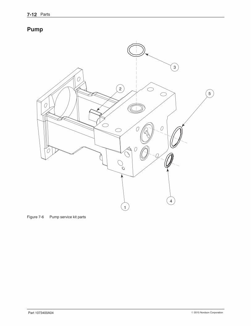
Parts7-12
Part 1073400A04 � 2015 Nordson Corporation
Pump
Figure 7-6 Pump service kit parts

Parts 7-13
Part 1073400A04� 2015 Nordson Corporation
Item StandardPart
PA Part(Note A) Description Quantity Note
— 1050729 1067875 Service kit, pump, 7.8 cc/rev —
1 - - - - - - - - - - - - � Pump 1
2 1033445 1033445 � Key, machine drive, 0.1875 x .70 in. 1
3 - - - - - - - - - - - - � O-ring, -118, Viton, 0.862 x 0.103 in. 1
4 - - - - - - - - - - - - � O-ring, -116, 0.737 x 0.103 in. 1
5 - - - - - - - - - - - - � O-ring, -123, 1.174 x 0.103 in. 1
NS - - - - - - - - - - - - � Screw, hex, cap, M8 x 90, 304stainless-steel
2 B
NS - - - - - - - - - - - - � Washer, flat, narrow, M8 2 B
NS - - - - - - - - - - - - � Grease, high-temperature, 0.50 oz 1
— 1031232 1067874 Service kit, pump O-rings —
3 940024 1047564 � O-ring, -118, 0.862 x 0.103 in. 1
4 941161 1047563 � O-ring, -116, 0.737 x 0.103 in. 1
5 941250 1067551 � O-ring, -123, 1.174 x 0.103 in. 1
NS - - - - - - - - - - - - � Grease, high-temperature, 0.50 oz 1
— 1037757 1067876 Service kit, seal, pump, 7.8 cc/rev —
NS - - - - - - - - - - - - � Shaft, pump, 7.8 cc 1
NS - - - - - - - - - - - - � Retaining ring, external, 75 2
NS - - - - - - - - - - - - � Pin, dowel, 0.185/0.184 dia. x 0.438long
1
NS - - - - - - - - - - - - � Seal, spring, 1/8 x 1 x 0.250 3
NS - - - - - - - - - - - - � Washer, 0.989 x 0.789 x 0.040 1
NS - - - - - - - - - - - - � Retaining ring, internal, 100, inverted 1
NS - - - - - - - - - - - - � O-ring,-147, 2.675 x 0.103 in. 1
NS - - - - - - - - - - - - � O-ring,-116, 0.737 x 0.103 in. 1
NS - - - - - - - - - - - - � O-ring, -123, 1.174 x 0.103 in. 1
NS - - - - - - - - - - - - � O-ring, -118, 0.862 x 0.103 in. 1
NS - - - - - - - - - - - - � Grease, high-temperature, 0.50 oz. 1
NS - - - - - - - - - - - - � Key, machine drive, 0.1875 x 0.70 1
NS - - - - - - - - - - - - � Tool, seal insertion 1
NOTE A: Parts designated as “PA” are recommended for use in product assembly applications with operatingtemperatures greater than 191 �C (375 �F). PA-type O-rings provide exceptionally high chemical andtemperature resistance.
B: Refer to Drive Assembly (Complete).
NS: Not Shown

Parts7-14
Part 1073400A04 � 2015 Nordson Corporation
Manifold
Figure 7-7 Manifold service kit parts (filtered manifold shown)

Parts 7-15
Part 1073400A04� 2015 Nordson Corporation
Item StandardPart
PA Part(Note A) Description Quantity Note
— 1031208 1069148 Service kit, manifold, 4-port, 1100 psi,filtered
—
— — 1067878 Service kit, manifold, 4-port, 1100 psi,non-filtered
—
— 1043464 — Service kit, manifold, 4-port, 600 psi,filtered
—
1 - - - - - - - - - - - - � Manifold assembly 1
2 - - - - - - - - - - - - � O-ring, -116, 0.737 x 0.103 in. 1
3 - - - - - - - - - - - - � O-ring, -123, 1.174 x 0.103 in. 1
4 - - - - - - - - - - - - � Screw, hex, cap, M8 x 90, 304stainless-steel
2
5 - - - - - - - - - - - - � Washer, flat, narrow, M8 2
6 - - - - - - - - - - - - � Connector, with O-ring, hose, 9/16-18 2
NS - - - - - - - - - - - - � Connector, 90 degree, 9/16-18 x9/16-18
1
NS - - - - - - - - - - - - � Grease, high-temperature, 0.50 oz 1
— 1031222 1067877 Service kit, valve, pressure control,1100 psi
—
7 - - - - - - - - - - - - � Valve, PCV, 1100 psi 1
— 1031221 1071502 Service kit, valve, pressure control,600 psi
—
7 - - - - - - — � Valve, PCV, 600 psi 1
8 1031235 — Filter, with O-ring, 50-mesh 1 B
1028305 1070899 Filter, with O-ring, 100-mesh 1 B
1031236 — Filter, with O-ring, 200-mesh 1 B
NS - - - - - - - - - - - - � O-ring, Viton, 3/4 in. tube 1
NS - - - - - - - - - - - - � Lubricant, Parker, high-temperature 1
NOTE A: Parts designated as “PA” are recommended for use in product assembly applications with operatingtemperatures greater than 191 �C (375 �F). PA-type O-rings provide exceptionally high chemical andtemperature resistance.
B: Present only on filtered manifolds.
NS: Not Shown

Parts7-16
Part 1073400A04 � 2015 Nordson Corporation
Drive Assembly (Complete)
13
13.5−16.3 N�m (10−12 ft-lb)
6.1−6.8 N�m (54−60 in.-lb)
Figure 7-8 Drive assembly (complete)

Parts 7-17
Part 1073400A04� 2015 Nordson Corporation
Item StandardPart Description Quantity Note
— 1031217 Service kit, drive assembly, 1/6 hp, 1100 psi,filtered
—
— 1031219 Service kit, drive assembly, 1/4 hp, 1100 psi,filtered
—
— 1043469 Service kit, drive assembly, 1/4 hp, 600 psi, filtered —
1 - - - - - - � Pump 1 A
2 - - - - - - � Manifold 1 B
3 - - - - - - � Motor 1 C
4 - - - - - - � Coupling, drive, 5/8 x 5/8 in. 1 D
5 - - - - - - � O-ring, -118, Viton, 0.862 x 0.103 in. 1
6 - - - - - - � O-ring, Viton, 1.188 x 1.388 x 0.094 in. 1 A
7 - - - - - - � O-ring, Viton, 0.750 x 0.938 x 0.094 in. 1 A
8 - - - - - - � Key, machine, drive, 0.1875 x 0.70 in. 1 D
9 - - - - - - � Screw, hex, cap, M8 x 90, 304 stainless-steel 2 A
10 - - - - - - � Washer, flat, narrow, M8 2 A
11 - - - - - - � Screw, hex, cap, M6 x 25 4
12 - - - - - - � Washer, lock, split, M6 4
13 - - - - - - � Bracket, pump support 1
NS - - - - - - � Capacitor 1 C
NS - - - - - - � Grease, high-temperature, 0.50 oz 1
— 1043467 Service kit, motor coupling, gerotor —
4 - - - - - - � Coupling, drive, 5/8 x 5/8 in. 1
8 - - - - - - � Key, machine, drive, 0.1875 x 0.70 in. 1
NOTE A: Provided in pump service kit. Refer to Pump earlier in this section for kit part numbers.
B: Refer to Manifold earlier in this section.
C: Refer to Motor earlier in this section.
D: Provided in the motor coupling service kit.
NS: Not Shown

Parts7-18
Part 1073400A04 � 2015 Nordson Corporation
Optional Equipment
Flow/Pressure Control and Pressure Indication
Part Description Quantity1032537 Flow controller, FC1, DuraBlue (also requires 1034042, 1028627, and 1030537) —
1034042 Valve, run-up PCV, 1100 psi —
1028627 Assembly, tachometer, generator, and cable, FC1, 0−225 VDC —
1030537 Kit, gauge, 1500 psi —
1034248 Kit, knob, adjustment, pressure control valve —
1037495 Kit, drain valve —
Expansion and Control Kits
Part Description Quantity1036607 Kit, I/O expansion card (digital) —
1063740 Kit, analog I/O board —
1053288 Kit, DeviceNet card —
1053289 Kit, Ethernet card —
1053300 Kit, PROFIBUS card —
1031175 Kit, 2-hose to 4-hose conversion, D10/D16 —
1050598 Kit, air control —
1030542 Kit, footswitch —
1047093 Kit, remote trigger —
FillMaster Accessory Kits
Part Description Quantity735162 Kit, lid, FillMaster, D10/D16 —
735161 Kit, sensor, FillMaster, D10/D16 —
General Melter Accessory Kits
Part Description Quantity1050595 Kit, support, hose, double —
1030530 Kit, hand-held applicator hanger —
1043074 Kit, return feed, D10/D10L/D16/D16L —

Technical Data 8-1
Part 1073400A04� 2015 Nordson Corporation
Section 8Technical Data
General Specifications
Item Data NoteMelter weight (empty)
D10 74 kg (162 lb)
D16 80 kg (176 lb)
Hose ports 2 to 4 A
Melt rate
D10 7.7 kg/hr (17.0 lb/hr)
D16 11.2 kg/hr (24.7 lb/hr)
Noise 64dB (A) at maximum pump speed B
Workplace temperature 0 to 50C (32 to 120 F)
Throughput rate
D10 12.5 kg/hr (27.5 lb/hr)
D16 20 kg/hr (44 lb/hr)
Pump rate22 or 35 kg/hr (48 or 77 lb/hr) at 60 Hz18 or 29 kg/hr (40 or 64 lb/hr) at 50 Hz C
NOTE A: Depends on the melter configuration.
B: The noise level is measured at a distance of 1 m (3.3 ft.) from the surface of the melter.
C: The pump rate for melter P/N 1039107 is 50 kg/hr (110 lb/hr) at 60 Hz.

Technical Data8-2
Part 1073400A04 � 2015 Nordson Corporation
Electrical Specifications NOTE: Refer to Configuring the Electrical Service in Section 3, Installation,for maximum amperage specifications.
Item Data NoteHose/gun heating capacity 2 or 4 hose/gun pairs A
Control temperature range 40 to 230 C (100 to 450 F)
Control temperature accuracy � .5 C (� 1 F)
IP rating IP 32
NOTE A: Depends on melter configuration
Heater Specifications NOTE: Refer to the hose and applicator manuals for hose/applicator heaterspecifications.
Location Voltage Wattage(see Note A)
Cold Resistance(see Note B)
Pump 240 V 400 130−152 ohms
Tank, D10 240 V 2 x 650 80.2−93.5 ohms each
Tank, D16 240 V 2 x 900 57.9−67.6 ohms each
NOTE A: Nominal wattage at 177−204 �C (350−400 �F).
B: Measured at room temperature for a previously heated element.

Technical Data 8-3
Part 1073400A04� 2015 Nordson Corporation
Motor and Pump Specifications
Item Data NoteViscosity range 1000–30,000 cps. A
Maximum hydraulic pressure 75 bar (1100 psi) B
Displacement 7.8 cc/rev
Motor size and speed C1/6 hp 54.6 rpm at 60 Hz or 45 rpm at 50 Hz1/4 hp 86.25 rpm at 60 Hz or 71.25 rpm at 50 Hz
NOTE A: The viscosity range for melter P/N 1039107 is 1000–10,000 cps.
B: The maximum hydraulic pressure for melter P/N 1039107 is 40 bar (600 psi).
C: The motor size and speed for melter P/N 1039107 is 135 rpm at 60 Hz.

Technical Data8-4
Part 1073400A04 � 2015 Nordson Corporation
Dimensions
392 mm(15.44 in.)307 mm
(12.07 in.)
878 mm(34.57 in.)
851 mm(33.50)
393 mm(15.48 in.)
584 mm(23.00 in)
647 mm(25.45 in.)
330 mm(12.99 in.)
1052 mm(41.40 in.) 163 mm
(6.40 in.)
Figure 8-1 D10/D16 melter dimensions
Figure 8-2 B900N mounting dimensions (from manifold)

Technical Data 8-5
Part 1073400A04� 2015 Nordson Corporation
Conduit Penetration Sizes
Figure 8-3 Conduit penetration sizes

Technical Data8-6
Part 1073400A04 � 2015 Nordson Corporation

Calculating Melter Power Requirements A-1
Part 1073400A04� 2015 Nordson Corporation
Appendix ACalculating Melter Power Requirements
Before locating the melter on the production floor or attaching hoses andapplicators to the melter, you must calculate the electrical power required bythe hoses and applicators and confirm that the required power does notexceed maximum allowable wattages. Properly calculating melter powerrequirements will prevent damage to the melter and identify the maximumallowable distance between the melter and the point at which the hot melt isdispensed.
The following three maximum wattages must be considered whencalculating melter power requirements.
� Single-component maximum—The wattage of any single hose orapplicator
� Hose/applicator pair maximum—The combined wattage of anyhose and applicator (hose/applicator pair)
� Two hose/applicator pair maximum—The combined wattage ofhose/applicator pairs 1 and 2 or hose/applicators pairs 3 and 4
If your Nordson representative has already calculated the hose/applicatorpower requirements and confirmed that the maximum allowable wattageswill not be exceeded, then no further calculation is necessary. However, youshould re-evaluate the hose and applicator power requirements before you:
� add a new hose or applicator to the melter that was not factored intothe original wattage evaluation
� replace an existing hose with a higher wattage hose or an existingapplicator with a higher wattage applicator

Calculating Melter Power RequirementsA-2
Part 1073400A04 � 2015 Nordson Corporation
To evaluate the hose/applicator power requirements
1. Identify all hose/applicator pairs based on the hose/applicator receptacleto which they are connected.
2. Examine the identification tag or plate on each hose and applicator andrecord the wattage of each in Column A of Table A-1. Enter a zero forany hose or applicator that is not installed.
3. Add the wattages of each hose/applicator pair and place the sum inColumn B of Table A-1.
4. Add the wattages of hose/applicator pairs 1 and 2 and hose/applicatorpairs 3 and 4 and place the sum in Column C of Table A-1.
5. Compare each of the wattages tabulated in Columns A, B, and C ofTable A-1 with the associated maximum allowable wattages inTable A-2.
6. Do one of the following:
� If each of the wattages calculated in step 5 do not exceed theassociated maximum allowable wattages listed in Table A-2, then thepower required by the hoses and applicators is within acceptablelimits.
� If any of the wattages calculated in step 5 does exceed anassociated maximum allowable wattage listed in Table A-2, then theconfiguration or position of the hose/applicator pairs must berearranged, shorter hoses must be used, or lower power applicatorsmust be used in order to reduce the power requirement.

Calculating Melter Power Requirements A-3
Part 1073400A04� 2015 Nordson Corporation
Table A-1 Hose/Gun Wattages
ComponentNumber Type/Size
A B C
ComponentWattage
Hose/Gun PairWattage
Two Hose/GunPair Wattage
Hose 1
Gun 1
Hose 2
Gun 2
Hose 3
Gun 3
Hose 4
Gun 4
Table A-2 Maximum Allowable Hose/Gun Wattages
Column inTable A-1 Component Maximum Wattage
A Any single hose or applicator 1000 W
B Any hose/gun pair 1200 W
CSum of hose/gun pairs 1 and 2 2000 W
Sum of hose/gun pairs 3 and 4 2000 W

Calculating Melter Power RequirementsA-4
Part 1073400A04 � 2015 Nordson Corporation

Operating Parameters B-1
Part 1073400A04� 2015 Nordson Corporation
Appendix BOperating Parameters
Operating parameters are organized in this appendix according to thelogical groups listed in Table B-1. For information about selecting andediting operating parameters, refer to Section 3, Installation, Setting Up theMelter.
NOTE: Parameter numbers that are reserved or that are not used do notappear in this appendix.
Table B-1 Parameter Groups
Group ParameterNumbers Group Description
Standard0 to 8 and10 to 14 Frequently used parameters
Pressure Control 15 to 17 Configure pressure settings
Temperature Control 20 to 26 Control heater function
Input Setup 30 to 39 Configure the standard and optional inputs
Output Setup 40 to 46 Configure the standard and optional outputs
Seven-day Clock 50 to 77 Configure the clock feature
Automatic Fill Timer 78 Configure the external motor control switch
PID Selection 80 to 91 Configure the PID settings

Operating ParametersB-2
Part 1073400A04 � 2015 Nordson Corporation
Standard
0 Enter PasswordDescription: A user-defined password that prevents unauthorized changes to setpoint
temperatures and operating parameters.
Value: 0 to 9999
Resolution: 1
Default Value: 4000
Format: —
Use: This parameter only appears if a password is created using parameter 11and then enabled using parameter 10.
NOTE: The melter remains in the password-protected mode for twominutes after the last key press. After exiting the setup mode, attemptingto re-enter the setup mode, even before two minutes has elapsed, willrequire you to re-enter the password.
1 Total Hours with Heaters On (Noneditable)
Description: A noneditable value that indicates the total number of hours that theheaters have been on.
Value: 999,999 (using abbreviated convention described below)
Resolution: 1 hour
Default Value: 0
Format: —
Use: The right display indicates up to 9999 hours of heater operation. Whenthe accumulated heater hours reaches 10,000, the display alternatesevery two seconds between the three left most digits (thousands) and thethree right digits (hundreds). For example, 10,001 hours would bedisplayed as ”10,” for two seconds and then ”001” for two seconds. Thecomma is present if parameter 20, Temperature Units, is set to degreesFahrenheit. A period is present if parameter 20 is set to degrees Celsius.
2 Fault Log (Noneditable)
Description: Stores a record of the last ten faults.
Value: —
Resolution: —
Default Value: _-F0 (unused log entry)
Format: F1, F2, F3, and F4
Use: Use the right-display scroll keys to review the log entries for the last tenfaults. Empty log entries are indicated by “_-F0.” Refer to Monitoring theMelter in Section 4, Operation.

Operating Parameters B-3
Part 1073400A04� 2015 Nordson Corporation
3 Change History Log (Noneditable)
Description: Records the last ten changes made to either the setpoint temperatures orthe operating parameters.
Value: —
Resolution: —
Default Value: P-_ (unused log entry)
Format: Refer to Section 3, Installation, Review Parameter and SetpointTemperature Changes.
Use: Use the right-display key to review the log entries for the last ten changesthat were made to the operating parameters or the setpoint temperatures.Empty log entries are indicated by “P-_.”
4 Ready Delay TimeDescription: The amount of time that will elapse after all of the components
have reached their setpoint temperature before the ready LEDwill turn on. The ready delay time only functions when thetemperature of the tank, at the time the melter is turned on, ismore than 27 C (50 F) from its setpoint temperature. Theready delay time begins when all components are within 3 C(5 F) of their respective setpoint temperature.
Value: 0 to 60 minutes
Resolution: 1 minute
Default Value: 0 minutes
Format: Left display “rd.” Right display, minutes or seconds remaining.
Use: The ready delay allows the contents of the tank an additionalamount of time to heat before pump turns on.
NOTE: The time remaining on the ready delay is indicated inminutes in the right display at the end of every automatic scancycle. When the delay time reaches 1 minute, the timeremaining appears in seconds.
5 Service Interval TimeDescription: The number of heater-on hours that must elapse before the service LED
turns on.
Value: 0 hours (disabled) to 8736 (one year)
Resolution: 1 hour
Default Value: 500 hours
Format: —
Use: Set the service interval time to signal a user-defined service check ormaintenance event, such as changing the filter. The service LED will turnon after the pre-set time elapses. With the melter in the scan mode, pressthe Clear/Reset key to turn off the service LED and reset the time.

Operating ParametersB-4
Part 1073400A04 � 2015 Nordson Corporation
Standard (contd)
6 Service LED Heater Hours (Noneditable)
Description: A timer indicates how many more hours the heaters need to remain onbefore the service LED illuminates (service required).
Value: 0 hours (disabled) to 9999
Resolution: 1 hour
Default Value: 0
Format: —
Use: The service interval time (parameter 5) must be enabled before thisparameter will work.
Note: Heater hours accumulate whenever the heaters LED is illuminated.
7 Motor Off DelayDescription: Determines the amount of time the motor will remain on after the
switching device turns off.
Value: 0 to 360 seconds
OR
- - - - (infinite)
Resolution: seconds
Default Value: 0 seconds
Format: —
Use: This parameter functions only when a switching device (switchedhand-held applicator hose, footswitch, etc.) is connected to the switchreceptacle.
8 Automatic Pump OnDescription: Determines if the pump will turn on automatically when the melter is
ready.
Value: 0 = disabled or 1 = enabled
Resolution: —
Default Value: 1 (enabled)
Format: —
Use: If Automatic Pump On is disabled, you must press the pump key to turnthe pump on.
If Automatic Pump On is enabled, the pump will turn on automaticallywhen the melter is ready.
NOTE: If Automatic Pump On is disabled (0) while the pump is running,the pump will remain on until the pump key is pressed.

Operating Parameters B-5
Part 1073400A04� 2015 Nordson Corporation
10 Enable or Disable the Melter PasswordDescription: Activates or deactivates the melter password. When password protection
is activated, component setpoint temperatures or melter operatingparameters cannot be changed until a valid password is entered usingparameter 0.
Value: 0 (disabled)
1 (enabled)
Resolution: —
Default Value: 0
Format: —
Use: A password must first be created using parameter 11 before it can beenabled or disabled using parameter 10.
11 Create PasswordDescription: A user-defined password that prevents unauthorized changes to
operating parameters or setpoint temperatures.
Value: 0 to 9999
Resolution: 1
Default Value: 5000
Format: —
Use: Refer to Section 4, Operation, Entering the Melter Password.
NOTE: When the password is created and enabled, parameter 10 will notappear again in the right display until the password is entered.
12 Change Hose 1 Output to Electric ApplicatorActivation
Description: Changes the proportioned 240 VAC current that is provided to the hose 1heater to a switched 240 VAC current that is used to activate amanifold-mounted electric applicator.
Value: 0 (disabled)
1 (enabled)
Resolution: —
Default Value: 0 (disabled)
Format: —
Use: Use only when a Nordson manifold-mounted electric applicator isinstalled and a switching device is connected to the melter’s switchreceptacle. Refer to the electric applicator manual for information onmounting and using the applicator.

Operating ParametersB-6
Part 1073400A04 � 2015 Nordson Corporation
Standard (contd)
13 Change Hose 2 Output to Electric ApplicatorActivation
Description: Changes the proportioned 240 VAC current that is provided to the hose 1heater to a switched 240 VAC current that is used to activate amanifold-mounted electric applicator.
Value: 0 (disabled)
1 (enabled)
Resolution: —
Default Value: 0 (disabled)
Format: —
Use: Use only when a Nordson manifold-mounted electric applicator isinstalled and a switching device is connected to the melter’s switchreceptacle. Refer to the electric applicator manual for information onmounting and using the applicator.
14 External Communications Lock-outDescription: Used as a safety feature when performing maintenance on the melter.
Prevents external control of the melter through standard or optionalinputs/outputs or network communications (optional)
Value: 0 (disabled)
or
1 (enabled)
Resolution: —
Default Value: 0 (disabled
Format: —
Use: Set parameter to 1 (enabled) before performing any maintenance on themelter. When enabled, all external control of the melter stops until theparameter is once again set to 0 (disabled).

Operating Parameters B-7
Part 1073400A04� 2015 Nordson Corporation
Pressure Control
15 Pressure SetpointDescription: Used to set the percentage of maximum output pressure (from
0−100 percent).
Value: 0 to 100 (percent)
Resolution: —
Default Value: 0 (disabled)
Format: —
Use: This parameter is available only when the optional analog input/output(I/O) board is installed on the melter. Refer to Section 7, Parts, for the I/Oboard kit part number. The pressure is displayed after the last applicatortemperature: the left display shows a P (for pressure) and the rightdisplay shows the pressure reading.
16 Over Pressure SetpointDescription: If the pressure in the system exceeds the value of this setting, an
over-pressure alarm will occur.
Value: 0 to 50 (percent) above the pressure setpoint (parameter 15)
Resolution: —
Default Value: 0
Format: —
Use: This parameter is available only when the optional analog I/O board isinstalled on the melter. Refer to Section 7, Parts, for the I/O board kit partnumber.
17 Under Pressure SetpointDescription: If the pressure in the system drops below the value of this setting, an
under-pressure alarm will occur.
Value: 0 to 50 (percent) below the pressure setpoint (parameter 15)
Resolution: —
Default Value: 0
Format: —
Use: This parameter is available only when the optional analog I/O board isinstalled on the melter. Refer to Section 7, Parts, for the I/O board kit partnumber.

Operating ParametersB-8
Part 1073400A04 � 2015 Nordson Corporation
Temperature Control
20 Temperature UnitsDescription: Sets the units for temperature display.
Value: C (degrees Celsius) or F (degrees Fahrenheit)
Resolution: 1 degree
Default Value: C
Format: —
Use: —
21 Over Temperature DeltaDescription: The number of degrees that the temperature of any component can
increase over its assigned setpoint temperature before an overtemperature fault (F3) will occur.
Value: 5 �C (10 �F) to 60 �C (110 �F)
Resolution: 1�C
1�F
Default Value: 15 �C (25 �F)
Format: —
Use: —
22 Under Temperature DeltaDescription: The number of degrees that the temperature of any component can
decrease from its setpoint temperature before an under temperature fault(F2) occurs.
Value: 5 �C (10 �F) to 60 �C (110 �F)
Resolution: 1�C
1�F
Default Value: 25 �C (50 �F)
Format: —
Use: —

Operating Parameters B-9
Part 1073400A04� 2015 Nordson Corporation
23 Standby DeltaDescription: The number of degrees by which all heated components will be
decreased when the applicator is placed into the standby mode.
Value: 5 �C to 190 �C (10 �F to 350 �F)
Resolution: 1 �C 1 �F
Default Value: 50 �C (100 �F)
Format: —
Use: A standby delta should be selected that results in a balance betweenmelter energy savings during periods of inactivity, the amount of time andenergy required to bring the melter back up to setpoint temperature, anda temperature at which the hot melt can be held in the tank for extendedperiods of time without charring. Refer to Section 4, Operation, UsingMelter Function Keys.
NOTE: The standby delta does not affect the under temperature delta(parameter 22).
24 Automatic Standby TimeoutDescription: The amount of time that must elapse after the last signal (applicator
driver) is sent to input 1 before the melter will enter the standby mode.The automatic standby timeout feature saves energy by allowing themelter to automatically go into the standby mode if the melter detects thatthe applicators are no longer firing.
Value: 0 to 1440 minutes (24 hours)
Resolution: 1 minute
Default Value: 0 (disabled)
Format: —
Use: 1. Change parameter 23 if required.
2. Set the control option for parameter 30 (input 1) to option 10(automatic standby)
NOTE: Only enable parameter 24 when a 24 VDC signal voltage isconnected to input 1. If there is no voltage on the input contacts when themelter is ready, the melter will enter the standby mode after the automaticstandby time.
25 Automatic Heaters Off TimeDescription: The amount of time that must elapse after the automatic standby time
elapses (parameter 24) before the heaters turn off.
Value: 0 to 1440 minutes (24 hours)
Resolution: 1 minute
Default Value: 0 (disabled)
Format: —
Use: Set parameter 24 (automatic standby timeout) to the desired value beforesetting parameter 25.

Operating ParametersB-10
Part 1073400A04 � 2015 Nordson Corporation
Temperature Control (contd)
26 Manual Standby TimeDescription: The amount of time that the melter will remain in the standby mode after
the standby key is pressed.
Value: 0 to 180 minutes
Resolution: 1 minute
Default Value: 0
Format: —
Use: Set the standby time when you want the operator to be able to place themelter into the standby mode for a limited period of time (break, lunch,etc.). When manual standby is enabled (value greater than 0 minutes),the standby LED blinks.
Set the standby delta (parameter 23) to the desired value before settingparameter 26.
Note: When a time value equal to or greater than 1 minute is entered, thestandby LED will flash to indicate that the manual standby timer iscounting down.

Operating Parameters B-11
Part 1073400A04� 2015 Nordson Corporation
Input Setup
30 Standard Input 1Description: Control options that determine the function of input 1.
Value: 0 – Input Disabled1 – Standby On/Off2 – Heaters On/Off3 – Motor Enable/Disable4 – Hose/Gun 1 Enable/Disable5 – Hose/Gun 2 Enable/Disable6 – Hose/Gun 3 Enable/Disable7 – Hose/Gun 4 Enable/Disable8 – Hose/Gun 5 Enable/Disable9 – Hose/Gun 6 Enable/Disable10 – Automatic standby11 – Motor 2 Enable/Disable (DuraBlue D50 and D100 melters only)13 − Automatic Fill Timer 114 − Automatic Fill Timer 2 (DuraBlue D50 and D100 melters only)
Resolution: 1
Default Value: 10
Format: —
Use: Multiple inputs can be set to the same input value. After one or moreinputs that have the same input value are energized, the inputfunctionality will not be considered inactive (off) until all of the inputs withthe same input value are de-energized (Multiple inputs set to the sameinput value are logical ORed.).
NOTE: Parameter 78, Automatic Fill Timer, must be set to a value of 1 orgreater in order to use option 13 or 14. Output option 6, Alert, can beused to signal when the Automatic Fill Timer expires.
31 Standard Input 2Description: Control options that determine the function of input 2.
Value: 0 – Input Disabled1 – Standby On/Off2 – Heaters On/Off3 – Motor Enable/Disable4 – Hose/Gun 1 Enable/Disable5 – Hose/Gun 2 Enable/Disable6 – Hose/Gun 3 Enable/Disable7 – Hose/Gun 4 Enable/Disable8 – Hose/Gun 5 Enable/Disable9 – Hose/Gun 6 Enable/Disable11 – Motor 2 Enable/Disable (DuraBlue D50 and D100 melters only)13 − Automatic Fill Timer 114 − Automatic Fill Timer 2 (DuraBlue D50 and D100 melters only)
Resolution: 1
Default Value: 1
Format: —
Use: Multiple inputs can be set to the same input value. After one or moreinputs that have the same input value are energized, the inputfunctionality will not be considered inactive (off) until all of the inputs withthe same input value are de-energized (Multiple inputs set to the sameinput value are logical ORed.).
NOTE: Parameter 78, Automatic Fill Timer, must be set to a value of 1 orgreater in order to use option 13 or 14. Output option 6, Alert, can beused to signal when the Automatic Fill Timer expires.

Operating ParametersB-12
Part 1073400A04 � 2015 Nordson Corporation
Input Setup (contd)
32 Standard Input 3Description: Control options that determine the function of input 3.
Value: 0 – Input Disabled1 – Standby On/Off2 – Heaters On/Off3 – Motor Enable/Disable4 – Hose/Gun 1 Enable/Disable5 – Hose/Gun 2 Enable/Disable6 – Hose/Gun 3 Enable/Disable7 – Hose/Gun 4 Enable/Disable8 – Hose/Gun 5 Enable/Disable9 – Hose/Gun 6 Enable/Disable11 – Motor 2 Enable/Disable (DuraBlue D50 and D100 melters only)13 − Automatic Fill Timer 114 − Automatic Fill Timer 2 (DuraBlue D50 and D100 melters only)
Resolution: 1
Default Value: 2
Format: —
Use: Multiple inputs can be set to the same input value. After one or moreinputs that have the same input value are energized, the inputfunctionality will not be considered inactive (off) until all of the inputs withthe same input value are de-energized (Multiple inputs set to the sameinput value are logical ORed.).
NOTE: Parameter 78, Automatic Fill Timer, must be set to a value of 1 orgreater in order to use option 13 or 14. Output option 6, Alert, can beused to signal when the Automatic Fill Timer expires.
33 Standard Input 4Description: Control options that determine the function of input 4.
Value: 0 – Input Disabled1 – Standby On/Off2 – Heaters On/Off3 – Motor Enable/Disable4 – Hose/Gun 1 Enable/Disable5 – Hose/Gun 2 Enable/Disable6 – Hose/Gun 3 Enable/Disable7 – Hose/Gun 4 Enable/Disable8 – Hose/Gun 5 Enable/Disable9 – Hose/Gun 6 Enable/Disable11 – Motor 2 Enable/Disable (DuraBlue D50 and D100 melters only)13 − Automatic Fill Timer 114 − Automatic Fill Timer 2 (DuraBlue D50 and D100 melters only)
Resolution: 1
Default Value: 4
Format: —
Use: Multiple inputs can be set to the same input value. After one or moreinputs that have the same input value are energized, the inputfunctionality will not be considered inactive (off) until all of the inputs withthe same input value are de-energized (Multiple inputs set to the sameinput value are logical ORed.).
NOTE: Parameter 78, Automatic Fill Timer, must be set to a value of 1 orgreater in order to use option 13 or 14. Output option 6, Alert, can beused to signal when the Automatic Fill Timer expires.

Operating Parameters B-13
Part 1073400A04� 2015 Nordson Corporation
34 – 35 Optional Inputs 5 and 6Description: Control options that determine the function of two of the optional inputs
provided when either the optional I/O expansion card (digital) or theanalog I/O board is installed on the CPU board.
Value: 0 – Input Disabled1 – Standby On/Off2 – Heaters On/Off3 – Motor Enable/Disable4 – Hose/Gun 1 Enable/Disable5 – Hose/Gun 2 Enable/Disable6 – Hose/Gun 3 Enable/Disable7 – Hose/Gun 4 Enable/Disable8 – Hose/Gun 5 Enable/Disable9 – Hose/Gun 6 Enable/Disable11 – Motor 2 Enable/Disable (DuraBlue D50 and D100 melters only)13 − Automatic Fill Timer 114 − Automatic Fill Timer 2 (DuraBlue D50 and D100 melters only)
Resolution: 1
Default Value: 0 (disabled)
Format: —
Use: Multiple inputs can be set to the same input value. After one or moreinputs that have the same input value are energized, the inputfunctionality will not be considered inactive (off) until all of the inputs withthe same input value are de-energized (Multiple inputs set to the sameinput value are logical ORed.).
NOTE: Parameter 78, Automatic Fill Timer, must be set to a value of 1 orgreater in order to use option 13 or 14. Output option 6, Alert, can beused to signal when the Automatic Fill Timer expires.
36 − 39 Optional Inputs 7, 8, 9, and 10Description: Control options that determine the function of four of the optional inputs
provided when the optional I/O expansion card (digital) is installed on theCPU board.
Value: 0 – Input Disabled1 – Standby On/Off2 – Heaters On/Off3 – Motor Enable/Disable4 – Hose/Gun 1 Enable/Disable5 – Hose/Gun 2 Enable/Disable6 – Hose/Gun 3 Enable/Disable7 – Hose/Gun 4 Enable/Disable8 – Hose/Gun 5 Enable/Disable9 – Hose/Gun 6 Enable/Disable11 – Motor 2 Enable/Disable (DuraBlue D50 and D100 melters only)13 − Automatic Fill Timer 114 − Automatic Fill Timer 2 (DuraBlue D50 and D100 melters only)
Resolution: 1
Default Value: 0 (disabled)
Format: —
Use: Multiple inputs can be set to the same input value. After one or moreinputs that have the same input value are energized, the inputfunctionality will not be considered inactive (off) until all of the inputs withthe same input value are de-energized (Multiple inputs set to the sameinput value are logical ORed.).
NOTE: Parameter 78, Automatic Fill Timer, must be set to a value of 1 orgreater in order to use option 13 or 14. Output option 6, Alert, can beused to signal when the Automatic Fill Timer expires.

Operating ParametersB-14
Part 1073400A04 � 2015 Nordson Corporation
Output Setup
40 − 42 Standard Outputs 1, 2, and 3Description: Determines the function of the output.
Value: 0 = Output Disabled1 = Ready2 = Ready and motor is on3 = Fault4 = Low level5 = Service LED is on6 = Alert (Potential fault)
Resolution: 1
Default Value: Output 1 = 1Output 2 = 3Output 3 = 4
Format: —
Use: Refer to Installing Melter Outputs in Section 3, Installation, for informationon setting up outputs.
When control option 6, Alert is selected, the output is active whenever themelter enters the two minute fault monitoring period. If the potential faultcondition clears before the end of the two minute period, the output signalends. Refer to Section 4, Operation, Monitor Melter Faults, forinformation about fault monitoring.
43 Optional Output 4Description: Control options that determine the function of one of the optional outputs
provided when either the optional I/O expansion card (digital) or the I/Oanalog board is installed on the CPU board.
Value: 0 = Output Disabled1 = Ready2 = Ready and motor is on3 = Fault4 = Low level5 = Service LED is on6 = Alert (Potential fault)
Resolution: 1
Default Value: 0 (all optional outputs)
Format: —
Use: Refer to the instruction sheet provided with the optional I/O expansioncard or analog I/O board for information about wiring and setting up theoptional outputs.
When control option 6, Alert is selected, the output is active whenever themelter enters the two minute fault monitoring period. If the potential faultcondition clears before the end of the two minute period, the output signalends. Refer to Section 4, Operation, Monitor Melter Faults, forinformation about fault monitoring.

Operating Parameters B-15
Part 1073400A04� 2015 Nordson Corporation
44 − 46 Optional Outputs 5, 6, and 7Description: Control options that determine the function of three of the optional
outputs provided when the optional I/O expansion card (digital) isinstalled on the CPU board.
Value: 0 = Output Disabled1 = Ready2 = Ready and motor is on3 = Fault4 = Low level5 = Service LED is on6 = Alert (Potential fault)
Resolution: 1
Default Value: 0 (all optional outputs)
Format: —
Use: Refer to the instruction sheet provided with the optional I/O expansioncard for information about wiring and setting up the optional outputs.
When control option 6, Alert is selected, the output is active whenever themelter enters the two minute fault monitoring period. If the potential faultcondition clears before the end of the two minute period, the output signalends. Refer to Section 4, Operation, Monitor Melter Faults, forinformation about fault monitoring.

Seven-day clock key
Operating ParametersB-16
Part 1073400A04 � 2015 Nordson Corporation
Seven-day Clock Before setting up the clock, refer to Using Melter Function Keys inSection 4, Operation, to familiarize yourself with the function and use of theclock feature.
If you are unfamiliar with the procedure for accessing and editing operatingparameters, refer to Section 3, Installation, Setting Up the Melter.
To set the clock
Refer to the examples on the next page.
1. Use parameter 50 to select the current day of the week.
2. Use parameter 51 to set the current time of day.
3. Create schedule 1 by:
a. Setting parameters 55 and 56 to the time of the day that the heatersshould turn on and off.
b. Setting parameters 57 and 58 to the time of the day that the meltershould enter and exit the standby mode.
4. Using parameters 60 through 68, create schedules 2 and 3 by repeatingstep 3.
5. Use parameters 71 through 77 to assign which of the four schedulesshould be used on each day of the week. Up to three schedules may beassigned each day (to support three work shifts). Each of the eightcontrol options (0 to 7) that is available in parameters 71 through 77assigns a different combination of the three schedules. Option 0 is usedhold the melter in the state dictated by the last clock transition until thenext clock transition occurs.
6. Press the Clock key.
In order for the clock to operate continuouslythroughout the week, a valid schedule mustbe assigned to every day of the week (param-eters 71 through 77).
To prevent unintentional activation of the clockthe default setting for parameters 71 through77 is schedule 0, which has no time valuesassigned to it. With the default set to sched-ule 0, unintentionally pressing the clock keywill have no affect on the melter.

Operating Parameters B-17
Part 1073400A04� 2015 Nordson Corporation
Example 1 To turn the heaters on at 0600 and turn them off at 0015 every day of theweek:
Par 55 = 0600Par 56 = 0015Par 60 = − − − −Par 61 = − − − −Par 71 through 77 = 1
Example 2 To turn the heaters on at 0700 and off at 1700 Monday through Friday, andturn the heaters off Saturday and Sunday:
Par 55 = 0700Par 56 = 1700Par 57 = − − − −Par 58 = − − − −Par 71 through 75 = 1Par 76 and 77 = 0
Example 3 To turn the heaters on at 0600 each morning, go into standby for lunch at1130, come out of standby after lunch at 1230, and turn the heaters off at1600 at the end of the day, every day of the week:
Par 55 = 0600Par 56 = 1600Par 57 = 1130Par 58 = 1230Par 71 through 75 = 1Par 71 and 77 = 1

Operating ParametersB-18
Part 1073400A04 � 2015 Nordson Corporation
Seven-day Clock (contd)
50 Current DayDescription: Used to set the current day of the week.
Value: 1 to 7 (1 = Monday, 2 = Tuesday, etc.)
Resolution: 1
Default Value: —
Format: —
Use: Refer to Section 4, Operation, Using Melter Function Keys, forinformation about the use and affects of the seven-day clock feature.
51 Current HourDescription: Used to set the local time of the day.
Value: 0000 to 2359 (European time format)
Resolution: 1 minute
Default Value: (Time set at factory)
Format: Hours, Hour: Minute, Minute
Use: This setting only needs to be made once for all daily schedules
55 Schedule 1 Heaters OnDescription: Used to set the time that the clock will turn on the heaters during
schedule 1.
Value: 0000 to 2359, - - - -
Resolution: 1 minute
Default Value: 0600
Format: Hours, Hour: Minute, Minute
Use: Set the desired time for the heaters to turn on.
To disable this parameter, set the parameter’s value to “- - - -” bysimultaneously pressing both of the right-display scroll keys.
56 Schedule 1 Heaters OffDescription: Used to set the time that the clock will turn off the heaters during
schedule 1.
Value: 0000 to 2359, - - - -
Resolution: 1 minute
Default Value: 1700
Format: Hours, Hour: Minute, Minute
Use: To disable this parameter, set the parameter’s value to “- - - -” bysimultaneously pressing both of the right-display scroll keys.

Operating Parameters B-19
Part 1073400A04� 2015 Nordson Corporation
57 Schedule 1 Enter StandbyDescription: Used to set the time that the melter will enter the standby mode during
schedule 1.
Value: 0000 to 2359, - - - -
Resolution: 1 minute
Default Value: - - - -
Format: Hour, Hour: Minute, Minute
Use: Set the time that the applicator will enter the standby mode duringschedule 1.
To disable this parameter, set the parameter’s value to “- - - -” bysimultaneously pressing both of the right-display scroll keys.
Note: Do not set an enter standby time that is outside of the time perioddefined by the schedule’s heater on and off time. The melter cannot enterthe standby mode when the heaters are off.
58 Schedule 1 Exit StandbyDescription: Used to set the time that the melter will exit the standby mode during
schedule 1.
Value: 0000 to 2359, - - - -
Resolution: 1 minute
Default Value: - - - -
Format: Hour, Hour: Minute, Minute
Use: Set the time that the applicator will exit the standby mode duringschedule 1.
To disable this parameter, set the parameter’s value to “- - - -” bysimultaneously pressing both of the right-display scroll keys.
Note: Do not set an exit standby time that is outside of the time perioddefined by the schedule’s heater on and off time. The melter cannot enterthe standby mode when the heaters are off.
60 Schedule 2 Heaters OnDescription: Used to set the time that the clock will turn on the heaters during
schedule 2.
Value: 0000 to 2359, - - - -
Resolution: 1 minute
Default Value: - - - -
Format: Hours, Hour: Minute, Minute
Use: Set the desired time for the heaters to turn on.
To disable this parameter, set the parameter’s value to “- - - -” bysimultaneously pressing both of the right-display scroll keys.

Operating ParametersB-20
Part 1073400A04 � 2015 Nordson Corporation
Seven-day Clock (contd)
61 Schedule 2 Heaters OffDescription: Used to set the time that the clock will turn off the heaters during
schedule 2.
Value: 0000 to 2359, - - - -
Resolution: 1 e
Default Value: - - - -
Format: Hours, Hour: Minute, Minute
Use: To disable this parameter, set the parameter’s value to “- - - -” bysimultaneously pressing both of the right-display scroll keys.
62 Schedule 2 Enter StandbyDescription: Used to set the time that the melter will enter the standby mode during
schedule 2.
Value: 0000 to 2359, - - - -
Resolution: 1 minute
Default Value: - - - -
Format: Hour, Hour: Minute, Minute
Use: Set the time that the applicator will enter the standby mode duringschedule 2.
To disable this parameter, set the parameter’s value to “- - - -” bysimultaneously pressing both of the right-display scroll keys.
Note: Do not set an enter standby time that is outside of the time perioddefined by the schedule’s heater on and off time. The melter cannot enterthe standby mode when the heaters are off.
63 Schedule 2 Exit StandbyDescription: Used to set the time that the melter will exit the standby mode during
schedule 2.
Value: 0000 to 2359, - - - -
Resolution: 1 minute
Default Value: - - - -
Format: Hour, Hour: Minute, Minute
Use: Set the time that the applicator will exit the standby mode duringschedule 2.
To disable this parameter, set the parameter’s value to “- - - -” bysimultaneously pressing both of the right-display scroll keys.
Note: Do not set an exit standby time that is outside of the time perioddefined by the schedule’s heater on and off time. The melter cannot enterthe standby mode when the heaters are off.

Operating Parameters B-21
Part 1073400A04� 2015 Nordson Corporation
65 Schedule 3 Heaters OnDescription: Used to set the time that the clock will turn on the heaters during
schedule 3.
Value: 0000 to 2359, - - - -
Resolution: 1 minute
Default Value: - - - -
Format: Hours, Hour: Minute, Minute
Use: Set the desired time for the heaters to turn on.
To disable this parameter, set the parameter’s value to “- - - -” bysimultaneously pressing both of the right-display scroll keys.
66 Schedule 3 Heaters OffDescription: Used to set the time that the clock will turn off the heaters during
schedule 3.
Value: 0000 to 2359, - - - -
Resolution: 1 minute
Default Value: - - - -
Format: Hours, Hour: Minute, Minute
Use: To disable this parameter, set the parameter’s value to “- - - -” bysimultaneously pressing both of the right-display scroll keys.
67 Schedule 3 Enter StandbyDescription: Used to set the time that the melter will enter the standby mode during
schedule 3.
Value: 0000 to 2359, - - - -
Resolution: 1 minute
Default Value: - - - -
Format: Hour, Hour: Minute, Minute
Use: Set the time that the applicator will enter the standby mode duringschedule 3.
To disable this parameter, set the parameter’s value to “- - - -” bysimultaneously pressing both of the right-display scroll keys.
Note: Do not set an enter standby time that is outside of the time perioddefined by the schedule’s heater on and off time. The melter cannot enterthe standby mode when the heaters are off.

Operating ParametersB-22
Part 1073400A04 � 2015 Nordson Corporation
Seven-day Clock (contd)
68 Schedule 3 Exit StandbyDescription: Used to set the time that the melter will exit the standby mode during
schedule 3.
Value: 0000 to 2359, - - - -
Resolution: 1 minute
Default Value: - - - -
Format: Hour, Hour: Minute, Minute
Use: Set the time that the applicator will exit the standby mode duringschedule 3.
To disable this parameter, set the parameter’s value to “- - - -” bysimultaneously pressing both of the right-display scroll keys.
Note: Do not set an exit standby time that is outside of the time perioddefined by the schedule’s heater on and off time. The melter cannot enterthe standby mode when the heaters are off.
71 Schedules for MondayDescription: Used to select which schedule(s) should be used on Monday.
Value: 0 – Remain at last clock transition1 – Use just schedule 12 – Use just schedule 23 – Use just schedule 34 – Use schedule 1 and 25 – Use schedule 2 and 36 – Use schedule 1 and 37 – Use schedule 1, 2, and 3
Resolution: 1
Default Value: 0
Format: —
Use: Selects the active schedule(s) for the day.
NOTES: If the 0 schedule option is used, the heaters will not turn onagain until the next scheduled heaters on time arrives.

Operating Parameters B-23
Part 1073400A04� 2015 Nordson Corporation
72 Schedules for TuesdayDescription: Used to select which schedule(s) should be used on Tuesday.
Value: 0 – Remain at last clock transition1 – Use just schedule 12 – Use just schedule 23 – Use just schedule 34 – Use schedule 1 and 25 – Use schedule 2 and 36 – Use schedule 1 and 37 – Use schedule 1, 2, and 3
Resolution: 1
Default Value: 0
Format: —
Use: Selects the active schedule(s) for the day.
NOTES: If the 0 schedule option is used, the heaters will not turn onagain until the next scheduled heaters on time arrives.
73 Schedules for WednesdayDescription: Used to select which schedule(s) should be used on Wednesday.
Value: 0 – Remain at last clock transition1 – Use just schedule 12 – Use just schedule 23 – Use just schedule 34 – Use schedule 1 and 25 – Use schedule 2 and 36 – Use schedule 1 and 37 – Use schedule 1, 2, and 3
Resolution: 1
Default Value: 0
Format: —
Use: Selects the active schedule(s) for the day.
NOTES: If the 0 schedule option is used, the heaters will not turn onagain until the next scheduled heaters on time arrives.

Operating ParametersB-24
Part 1073400A04 � 2015 Nordson Corporation
Seven-day Clock (contd)
74 Schedules for ThursdayDescription: Used to select which schedule(s) should be used on Thursday.
Value: 0 – Remain at last clock transition1 – Use just schedule 12 – Use just schedule 23 – Use just schedule 34 – Use schedule 1 and 25 – Use schedule 2 and 36 – Use schedule 1 and 37 – Use schedule 1, 2, and 3
Resolution: 1
Default Value: 0
Format: —
Use: Selects the active schedule(s) for the day.
NOTES: If the 0 schedule option is used, the heaters will not turn onagain until the next scheduled heaters on time arrives.
75 Schedules for FridayDescription: Used to select which schedule(s) should be used on Friday.
Value: 0 – Remain at last clock transition1 – Use just schedule 12 – Use just schedule 23 – Use just schedule 34 – Use schedule 1 and 25 – Use schedule 2 and 36 – Use schedule 1 and 37 – Use schedule 1, 2, and 3
Resolution: 1
Default Value: 0
Format: —
Use: Selects the active schedule(s) for the day.
NOTES: If the 0 schedule option is used, the heaters will not turn onagain until the next scheduled heaters on time arrives.

Operating Parameters B-25
Part 1073400A04� 2015 Nordson Corporation
76 Schedules for SaturdayDescription: Used to select which schedule(s) should be used on Saturday.
Value: 0 – Remain at last clock transition1 – Use just schedule 12 – Use just schedule 23 – Use just schedule 34 – Use schedule 1 and 25 – Use schedule 2 and 36 – Use schedule 1 and 37 – Use schedule 1, 2, and 3
Resolution: 1
Default Value: 0
Format: —
Use: Selects the active schedule(s) for the day.
NOTES: If the 0 schedule option is used, the heaters will not turn onagain until the next scheduled heaters on time arrives.
77 Schedules for SundayDescription: Used to select which schedule(s) should be used on Sunday.
Value: 0 – Remain at last clock transition1 – Use just schedule 12 – Use just schedule 23 – Use just schedule 34 – Use schedule 1 and 25 – Use schedule 2 and 36 – Use schedule 1 and 37 – Use schedule 1, 2, and 3
Resolution: 1
Default Value: 0
Format: —
Use: Selects the active schedule(s) for the day.
NOTES: If the 0 schedule option is used, the heaters will not turn onagain until the next scheduled heaters on time arrives.

Operating ParametersB-26
Part 1073400A04 � 2015 Nordson Corporation
Automatic Fill Timer
78 Automatic Fill TimerDescription: A count-down timer that can be associated with a switch connected to an
input.
Value: 0 to 90 seconds
Resolution: 1
Default Value: 0 (Disabled)
Format: —
Use: Used in conjunction with input control option 13 or 14. Enable outputcontrol option 6, Alert, to send a signal when the timer expires.
PID Selection
80−87 PID Selection for Hose/Gun Receptacles 1, 2, 3,and 4
Description: Used to change the preset PID selections. Use parameter 80 to selectthe value for hose 1, parameter 81 to select the value for applicator 1,and so on, up to hose 4/gun 4.
Value: 0 = Hose1 = Standard applicator2 = Large applicator3 = Air heater
Resolution: —
Default Value: 0 or 1 depending on the channel type (hose or applicator)
Format: —
Use: Consult your Nordson representative before changing PID settings.
88 − 91 PID Selection for Hose/Gun Receptacles 5, 6, 7,and 8 (DuraBlue D25, D50, and D100 melters only)
Description: Used to change the preset PID selections. Use parameter 88 to selectthe value for hose 5, parameter 89 to select the value for applicator 5,and so on, up to hose 8/gun 8.
Value: 0 = Hose1 = Standard applicator2 = Large applicator3 = Air heater
Resolution: —
Default Value: 0 or 1 depending on the channel type (hose or applicator)
Format: —
Use: Consult your Nordson representative before changing PID settings.

Melter Communications C-1
Part 1073400A04� 2015 Nordson Corporation
Appendix CMelter Communications
This appendix describes the installation and use of the NordsonConfiguration Manager (NCM) communications utility. With this utility youcan:
� transfer operating parameters and temperature set-points betweenmelters
� upgrade or reload your melter’s firmware
Software Availability If you do not already have the NCM utility, you can download it from theinternet by navigating to www.enordson.com/support.
If you do not have a connection to the internet, you can request a softwareCD from your Nordson representative.
System Requirements The following hardware and software requirements are necessary to installand run Blue Series software:
� Any ProBlue adhesive melter or a DuraBlue 10/16 adhesive melter
� Serial cable
� Personal computer with:
� CD-RW drive or 3.5-inch floppy drive
� Available COM port
� 640 x 480 color monitor
� Windows 95, 98 (second edition), ME, XP, or 2000
� Internet Explorer version 4.0 or later (IE 5.0 is recommended)
� Administrative privileges (Windows XP, 2000, and NT)

Melter CommunicationsC-2
Part 1073400A04 � 2015 Nordson Corporation
Installing the Software To meet your specific installation conditions, two versions of the softwareare available. Refer to Table C-1 to determine which version you need.
Table C-1 Blue Series Software Versions
Version Use When...
Single installation file:
BlueSeries.exe
You are downloading the software from www.enordson.com and the PC you aredownloading onto is connected or can be connected to the melter
OR
You are downloading the software from www.enordson.com onto a PC that can not beconnected to the melter, but the PC does have a CD-RW and the PC that is connected tothe melter does have a CD drive
OR
You have a CD with the software and you have a PC with a CD drive that can beconnected to the melter
Self-extracting span diskette set:
BlueSeriesSpan.exe
You are downloading the software from www.enordson.com onto a PC that cannot beconnected to the melter and the PC that is connected to your melter only has a 3.5-inchfloppy drive
When the installation file is executed, an installation wizard will detect youroperating system and start the installation routine.
NOTE: Installing the NCM for the first time also installs the latest version ofthe melter’s firmware.

Melter Communications C-3
Part 1073400A04� 2015 Nordson Corporation
To install Blue Series software1. Do one of the following:
� If you are installing using the single file installation, locate anddouble-click on the file BlueSeries.exe.
� If you are installing from the span diskette set, insert Disk 1, andthen locate and double-click on the file Setup.exe.
The Blue Series Software Setup wizard appears.
2. Click Next, and then follow the on-screen instructions. If you areinstalling from the span disk set, you will be prompted to insert additionaldiskettes (2 through 5) as required by your operating system.
NOTE: When prompted to select an installation location, NordsonCorporation recommends that you select the default location offered.
3. When the installation complete message appears, click Finished.
Removing the Software from Your PCUse the Remove feature provided by the Blue Series InstallShield� Wizardto remove the software from your PC. Removing Blue Series software fromyour PC will not remove melter settings files that you have saved using theNCM. Settings files (.ncm extension) are stored in your Windows MyDocuments folder.
NOTE: Windows XP, 2000, and NT users must have administrator rights inorder to remove software from their PC.
To remove Blue Series software 1. From the Windows Start menu, select Settings > Control Panel, and
then double-click Add/Remove Programs.
The Add/Remove Programs dialog box appears.
2. Select Blue Series Software from the list, and then click Remove.

11 22
00
44 55
33
66
99
Serial port
Configuration Managerdesktop icon
Melter CommunicationsC-4
Part 1073400A04 � 2015 Nordson Corporation
Connecting the PC and the Melter
Connect a serial cable between the PC COM port (selected during thesoftware installation routine) and the serial port connection (COM port) onyour melter’s control panel.
Using Nordson Configuration ManagerConfiguration Manager is launched from your Windows desktop using theicon shown to the left.
Use Configuration Manager when you want to... � copy melter settings from one melter to another melter
� create and save more than one version of melter settings
� upgrade or restore a melter’s firmware
Configuration Manager communicates with your melter through a PCconnected to your melter’s serial port. Once connected, ConfigurationManager offers the choice of saving settings, restoring settings, orupgrading the melter’s firmware.
The first time you download and install Configuration Manager, the latestversion of the melter’s firmware is also downloaded.

Melter Communications C-5
Part 1073400A04� 2015 Nordson Corporation
Saving and Restoring Melter Settings Saving settings copies all current set-point and operating parameter valuesto your PC. Saved settings can be transferred back to the same melter or toany other compatible Blue Series adhesive melter.
To save melter settings 1. Place the melter into the configuration mode by simultaneously pressing
the Standby and Setup keys.
“COnF” appears in the right display.
2. Double-click the NCM icon on the Windows desktop.
The NCM dialog box appears.
3. Click Select Device.
The Select Product dialog box appears.
4. Select your melter from the list, and then click Ok.
The Select COM Port dialog box appears.
5. Select the COM port you are using to connect to the melter, and thenclick Ok.
The PC and melter establish communications and a picture of the melteryou selected appears in the device status area. The right side of thestatus area indicates “CONNECTED”.
6. Click Save Settings.
The Save As dialog box appears.
NOTE: The default location for saving settings files is Windows MyDocuments folder. To avoid loosing saved settings files, NordsonCorporation recommends that you do not change the default savelocation.
7. Type a file name to identify the group of settings you are saving, andthen click Save.
The save settings progress bar indicates the status of the save. Whenthe save is complete, the melter automatically returns to the scan mode.
NOTE: If you are using the NCM to save multiple variations of meltersettings, use a file naming convention that will allow you to easilyassociate each settings file (.ncm extension) with its related process orend-use.
8. Click Ok to close the NCM.
Melter CommunicationsC-6
Part 1073400A04 � 2015 Nordson Corporation
Saving and Restoring Melter Settings (contd)
To restore melter settings 1. Follow steps 1 through 5 of To save melter settings.
2. Click Restore Settings.
The Open dialog box appears.
3. Select the settings file (.ncm extension) that you want to restore, andthen click Open.
The Restore Settings progress bar indicates the status of the restore.When the restore is complete, the melter automatically returns to thescan mode.
Upgrading or Restoring Melter Firmware Use the NCM to upgrade your melter to a newer version of firmware orreload the current version of the firmware. The version of Blue Seriesadhesive melter firmware that is currently available is posted on the internetat www.enordson.com/support.
NOTE: The version of firmware that is loaded on your melter appears onthe control panel when the melter is first switched on.
During the upgrade process, all current melter settings are downloaded andsaved on your PC. After upgrading or restoring a melter’s firmware, you canuse the NCM to restore the pre-upgrade settings.
CAUTION: The upgrade process returns the melter’s settings to factoryconfiguration, with the exception that current heater hours data is saved.Data in both the fault log and the change log is lost after upgrading thefirmware.

Melter Communications C-7
Part 1073400A04� 2015 Nordson Corporation
To upgrade or reload melter firmware 1. Connect your PC to the melter. Refer to Connecting the PC and the
Melter earlier in this guide.
2. Place the melter into the upgrade mode by switching the melter off andthen on again, and then immediately pressing and holding both theSetup and left display Scroll key.
UPLOAd appears in the right display.
3. Double-click the NCM icon on the Windows desktop.
The NCM dialog box appears.
4. Click Select.
The device dialog box appears.
5. Select your melter from the list, and then click Ok.
The Select COM Port dialog box appears.
6. Select the COM port you are using to connect to the melter, and thenclick Ok.
The PC and melter establish communications and a picture of the melteryou selected appears in the device status area. The right side of thestatus area indicates Connected.
7. Click Upgrade.
The Select Upgrade dialog box appears.
8. In the Available Upgrades list, select the firmware version you want toupload to the melter, and then click Ok.
The upgrade warning message appears.
9. Click OK.
The Upgrade in Progress dialog box appears. The upgrade can takeas long as 12 minutes. When the upgrade is complete, the Successdialog box appears and the melter restarts.

Melter CommunicationsC-8
Part 1073400A04 � 2015 Nordson Corporation
To upgrade or reload melter firmware (contd)
CAUTION: Once the uprade progress bar appears, do not interrupt theupgrade process for any reason. Interupting the upgrade can corrupt themelter’s firmware, which will require replacement of the IC chip(IC service kit P/N 1018817).
10. Click OK.
The communications link between the melter and the PC is terminated.
11. Do one of the following:
� To restore pre-upgrade melter settings, go to To restore pre-upgrademelter settings on the next page.
� To close the NCM, click Exit.
� To restore melter settings other than the settings that were in use bythe melter before the upgrade, go to Saving and Restoring MelterSettings earlier in this guide.
To restore pre-upgrade melter settings 1. Place the melter into the configuration mode by simultaneously pressing
the Standby and Setup keys.
“COnF” appears in the right display.
2. Click Connect.
The Select COM Port dialog box appears.
3. Select the COM port you are using to connect to the melter, and thenclick Ok.
The PC and melter establish communications and a picture of the melteryou selected appears in the device status area. The right side of thestatus area indicates “CONNECTED”.
4. Click Restore Pre-Upgrade Settings.
The pre-upgrade settings are restored and the melter returns to the scanmode.
5. Click Exit to close the NCM.

Melter Communications C-9
Part 1073400A04� 2015 Nordson Corporation
Troubleshooting
Using Nordson Configuration Manager Symptom/Message Action
After selecting a device and the COM port, an Access Deniedmessage appears.
PC-to-Blue communications may be running or anotherapplication may be using the COM port. Close Internet Explorerand end the communications connection (if prompted). Close allother applications.
Melter in UPLOAd mode, the update process has not beeninitiated, and you want to stop and exit the UPLOAd mode, butyou cannot get the melter out of UPLOAd.
Cycle power to the melter at the local power disconnect switch.
CAUTION: Ensure that the firmware update process is notrunning before taking power off of the melter.
UPLOAd does not appear on the melter’s display when you pressthe Setup and left display scroll keys.
You must cycle the control switch while holding the Setup and leftdisplay scroll keys.
Attempted a firmware update, but the melter display still indicatesUPLOAd.
OR
Attempted a firmware update, but the PC has stopped respondingor was interrupted during the update process.
Using the local power disconnect switch, cycle power to themelter, and then re-attempt the update.
If the update is unsuccessful or the melter will not reboot, thecentral processor chip may be corrupted. Replace the CPUboard.

Melter CommunicationsC-10
Part 1073400A04 � 2015 Nordson Corporation


