18
Copyright © 2014 Dynalene, Inc. All Rights Reserved. HC Engineering Guide | 0 Dynalene HC engineering guide
Copyright © 2014 Dynalene, Inc. All Rights Reserved. HC Engineering Guide | 0
Dynalene HC engineering guide
Copyright © 2014 Dynalene, Inc. All Rights Reserved. HC Engineering Guide | 1
Contents
Product Overview 2
Packing & Shipping 2
Vapor Pressure 2
Shelf Life 3
Metals Compatibility 3
Gasket & Polymer Compatibility 4
General Installation Guidelines 4
Retrofitting for Dynalene HC 6
Contaminants in Dynalene HC 8
New Systems Using Dynalene HC 8
Dynalene HC Property Comparisons 9
HC-50 Properties 10
HC-40 Properties 11
HC-30 Properties 12
HC-20 Properties 13
HC-10 Properties 14
Notice to all System Operators 15
Toxicological Report 15
Product Disclaimer 17
Locations and Contact Information 17
Copyright © 2014 Dynalene, Inc. All Rights Reserved. HC Engineering Guide | 2
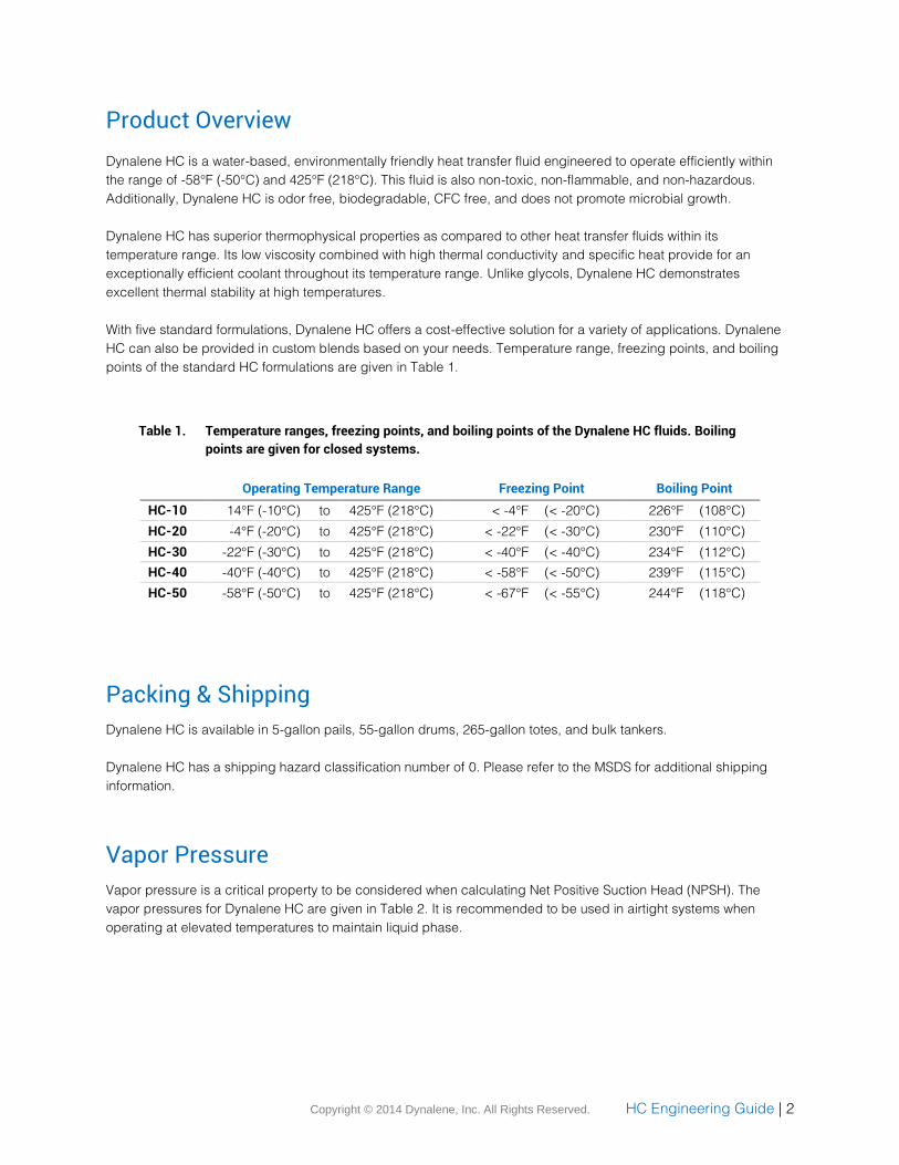
Product Overview
Dynalene HC is a water-based, environmentally friendly heat transfer fluid engineered to operate efficiently within
the range of -58°F (-50°C) and 425°F (218°C). This fluid is also non-toxic, non-flammable, and non-hazardous.
Additionally, Dynalene HC is odor free, biodegradable, CFC free, and does not promote microbial growth.
Dynalene HC has superior thermophysical properties as compared to other heat transfer fluids within its
temperature range. Its low viscosity combined with high thermal conductivity and specific heat provide for an
exceptionally efficient coolant throughout its temperature range. Unlike glycols, Dynalene HC demonstrates
excellent thermal stability at high temperatures.
With five standard formulations, Dynalene HC offers a cost-effective solution for a variety of applications. Dynalene
HC can also be provided in custom blends based on your needs. Temperature range, freezing points, and boiling
points of the standard HC formulations are given in Table 1.
Table 1. Temperature ranges, freezing points, and boiling points of the Dynalene HC fluids. Boiling
points are given for closed systems.
Operating Temperature Range Freezing Point Boiling Point
HC-10 14°F (-10°C) to 425°F (218°C) < -4°F (< -20°C) 226°F (108°C)
HC-20 -4°F (-20°C) to 425°F (218°C) < -22°F (< -30°C) 230°F (110°C)
HC-30 -22°F (-30°C) to 425°F (218°C) < -40°F (< -40°C) 234°F (112°C)
HC-40 -40°F (-40°C) to 425°F (218°C) < -58°F (< -50°C) 239°F (115°C)
HC-50 -58°F (-50°C) to 425°F (218°C) < -67°F (< -55°C) 244°F (118°C)
Packing & Shipping
Dynalene HC is available in 5-gallon pails, 55-gallon drums, 265-gallon totes, and bulk tankers.
Dynalene HC has a shipping hazard classification number of 0. Please refer to the MSDS for additional shipping
information.
Vapor Pressure
Vapor pressure is a critical property to be considered when calculating Net Positive Suction Head (NPSH). The
vapor pressures for Dynalene HC are given in Table 2. It is recommended to be used in airtight systems when
operating at elevated temperatures to maintain liquid phase.
Copyright © 2014 Dynalene, Inc. All Rights Reserved. HC Engineering Guide | 3
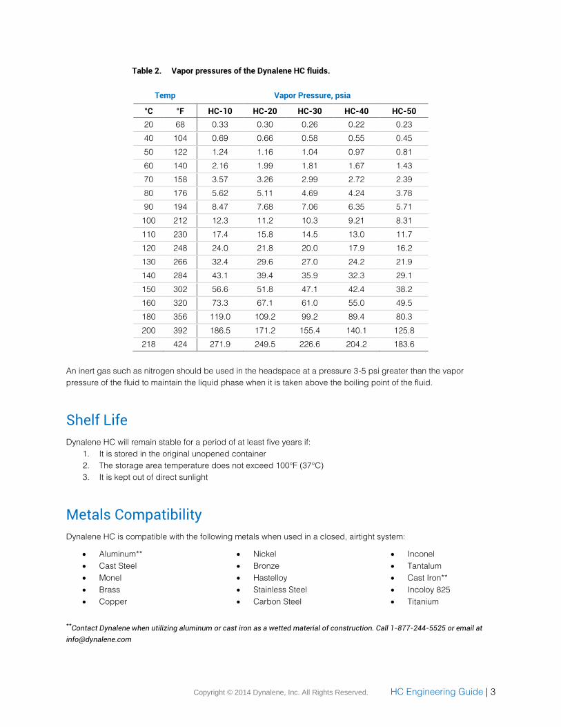
Table 2. Vapor pressures of the Dynalene HC fluids.
Temp Vapor Pressure, psia
°C °F HC-10 HC-20 HC-30 HC-40 HC-50
20 68 0.33 0.30 0.26 0.22 0.23
40 104 0.69 0.66 0.58 0.55 0.45
50 122 1.24 1.16 1.04 0.97 0.81
60 140 2.16 1.99 1.81 1.67 1.43
70 158 3.57 3.26 2.99 2.72 2.39
80 176 5.62 5.11 4.69 4.24 3.78
90 194 8.47 7.68 7.06 6.35 5.71
100 212 12.3 11.2 10.3 9.21 8.31
110 230 17.4 15.8 14.5 13.0 11.7
120 248 24.0 21.8 20.0 17.9 16.2
130 266 32.4 29.6 27.0 24.2 21.9
140 284 43.1 39.4 35.9 32.3 29.1
150 302 56.6 51.8 47.1 42.4 38.2
160 320 73.3 67.1 61.0 55.0 49.5
180 356 119.0 109.2 99.2 89.4 80.3
200 392 186.5 171.2 155.4 140.1 125.8
218 424 271.9 249.5 226.6 204.2 183.6
An inert gas such as nitrogen should be used in the headspace at a pressure 3-5 psi greater than the vapor
pressure of the fluid to maintain the liquid phase when it is taken above the boiling point of the fluid.
Shelf Life
Dynalene HC will remain stable for a period of at least five years if:
1. It is stored in the original unopened container
2. The storage area temperature does not exceed 100°F (37°C)
3. It is kept out of direct sunlight
Metals Compatibility
Dynalene HC is compatible with the following metals when used in a closed, airtight system:
Aluminum**
Cast Steel
Monel
Brass
Copper
Nickel
Bronze
Hastelloy
Stainless Steel
Carbon Steel
Inconel
Tantalum
Cast Iron**
Incoloy 825
Titanium
**Contact Dynalene when utilizing aluminum or cast iron as a wetted material of construction. Call 1-877-244-5525 or email at
Copyright © 2014 Dynalene, Inc. All Rights Reserved. HC Engineering Guide | 4
Caution: Do not use magnesium, zinc, zinc-plated, or galvanized metals in the heat transfer loop containing
Dynalene HC. These metals are acceptable to use as support framing, electrical conduit, and structural
components. If HC spills or splashes on any metals rinse immediately with water to prevent surface discoloration.
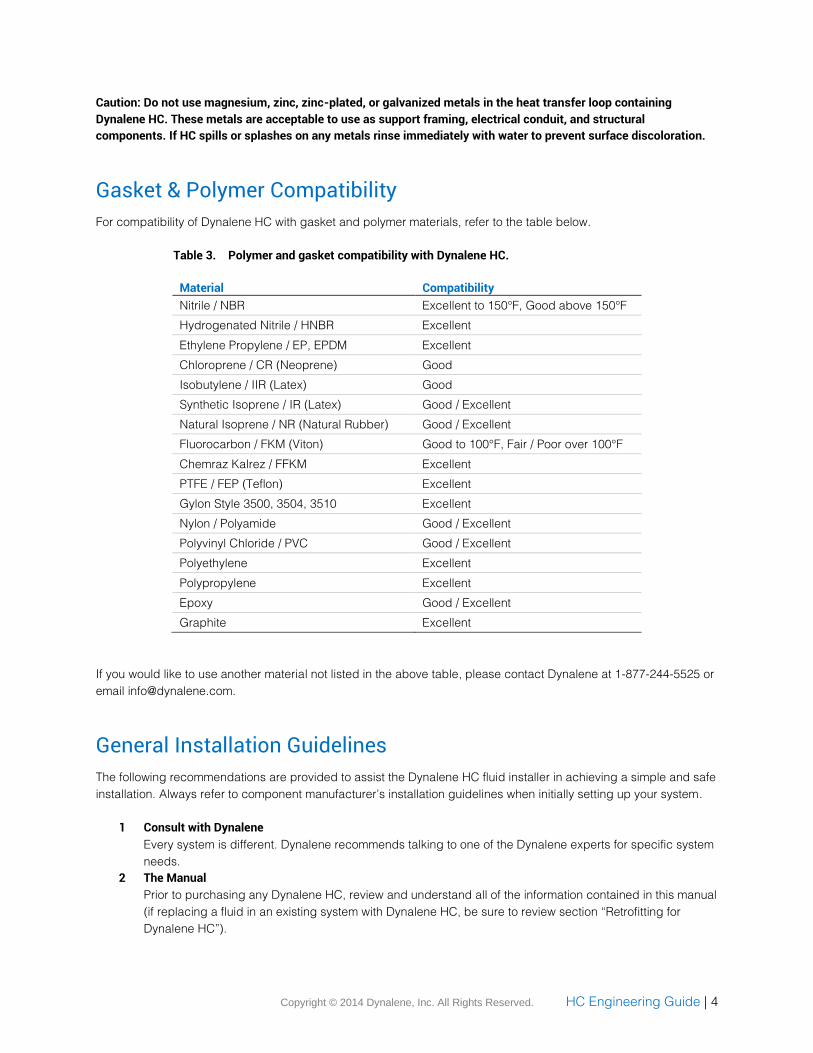
Gasket & Polymer Compatibility
For compatibility of Dynalene HC with gasket and polymer materials, refer to the table below.
Table 3. Polymer and gasket compatibility with Dynalene HC.
Material Compatibility
Nitrile / NBR Excellent to 150°F, Good above 150°F
Hydrogenated Nitrile / HNBR Excellent
Ethylene Propylene / EP, EPDM Excellent
Chloroprene / CR (Neoprene) Good
Isobutylene / IIR (Latex) Good
Synthetic Isoprene / IR (Latex) Good / Excellent
Natural Isoprene / NR (Natural Rubber) Good / Excellent
Fluorocarbon / FKM (Viton) Good to 100°F, Fair / Poor over 100°F
Chemraz Kalrez / FFKM Excellent
PTFE / FEP (Teflon) Excellent
Gylon Style 3500, 3504, 3510 Excellent
Nylon / Polyamide Good / Excellent
Polyvinyl Chloride / PVC Good / Excellent
Polyethylene Excellent
Polypropylene Excellent
Epoxy Good / Excellent
Graphite Excellent
If you would like to use another material not listed in the above table, please contact Dynalene at 1-877-244-5525 or
email [email protected].
General Installation Guidelines
The following recommendations are provided to assist the Dynalene HC fluid installer in achieving a simple and safe
installation. Always refer to component manufacturer’s installation guidelines when initially setting up your system.
1 Consult with Dynalene
Every system is different. Dynalene recommends talking to one of the Dynalene experts for specific system
needs.
2 The Manual
Prior to purchasing any Dynalene HC, review and understand all of the information contained in this manual
(if replacing a fluid in an existing system with Dynalene HC, be sure to review section “Retrofitting for
Dynalene HC”).
Copyright © 2014 Dynalene, Inc. All Rights Reserved. HC Engineering Guide | 5
3 Presence of Air
It is always recommended to eliminate the presence of air in your system. In closed systems, Dynalene
advises to use a nitrogen blanket 3-5 psi above the vapor pressure of the fluid. This will prevent outside
oxygen from entering the system.
4 Maximum Surface Temperature
Surface temperature of heat source components in systems using Dynalene HC should not exceed 500°F
(260°C). Fluid velocity should be maintained between 4 to 8 ft/sec to reduce overheating of the heater
walls.
5 Using Electric Resistance Heaters
In-line electric resistance heaters used in Dynalene HC systems should not exceed a maximum watt
density of 60 W/in2 with a minimum fluid velocity of 6 to 8 ft/sec. Watt density not exceeding 45 W/in2 is
recommended for direct “tank” immersion electric resistance heater applications.
Ensure electrical connections are properly contained and kept away from splash or spill areas. If there is a
thermal contact between the cold surface and electrical connection, there may be condensation resulting
in short circuiting.
6 Pump Equipment
Pumps with mechanical seals should be evaluated by the pump manufacturer. Dynalene recommends
using tungsten carbide or silicon carbide mechanical seals. Seal materials such as polymer, carbon, or soft
ceramics may abrade over time, causing leakage. Sealless, magnetically driven, and canned pumps are
also acceptable.
Elastomer compatibility, working temperatures and pressure limitations of a mechanical seal assembly
should be reviewed by the pump manufacturer prior to operating in a system with Dynalene HC.
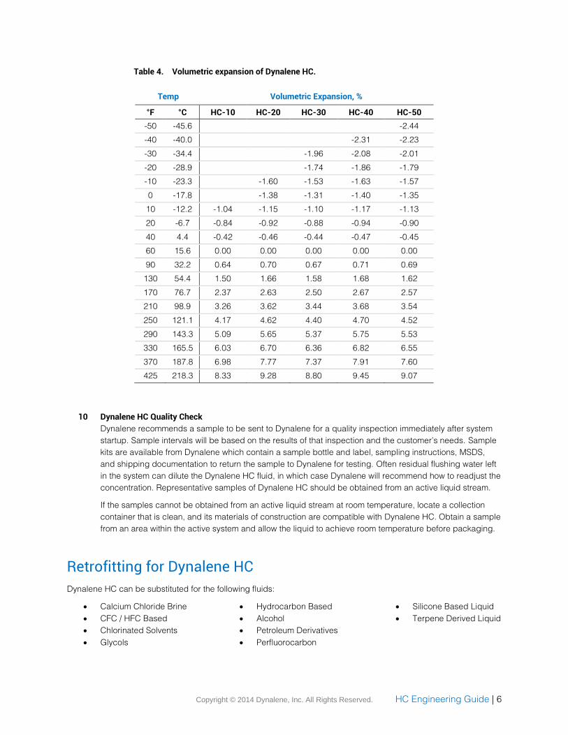
7 Volumetric Expansion
Volumetric expansion and/or contraction of Dynalene HC must be taken into consideration when
calculating the overall fluid volume within the entire system. For systems with large temperature ranges,
consider using an expansion tank. Refer to the volumetric expansion in Table 4.
8 Reservoir Tank
Purging and eliminating air from the headspace above the Dynalene HC in the reservoir tank is
recommended. Return fluid piping should enter a storage tank below the Dynalene HC fluid surface to
prevent foaming, air entrapment, and bubbles. Air bubbles can contribute to the damaging effects such as
erosion, corrosion, and loss of heat transfer.
9 Pressure Relief Valve Considerations
Pressure relief valves should be cleaned of salt residue to prevent clogging or sticking if Dynalene HC is
released through the valve.
Valve Sizing: Relief valve sizing depends on whether the valve is located to relieve liquid or vapor from
Dynalene HC. Regarding liquid, the relief valves should be sized using the Dynalene HC liquid
properties to permit sufficient liquid volumetric flow to match or exceed the maximum possible
pressure building volume rate increase in the system. If the relief temperature is above the fluid
saturated vapor temperature for the discharge pressure, flashing will occur and relief valve
must be sized for two-phase flow. Dynalene vapor is primarily water (steam). The latent heat of
water should be used to calculate flashing.
Copyright © 2014 Dynalene, Inc. All Rights Reserved. HC Engineering Guide | 6
Table 4. Volumetric expansion of Dynalene HC.
Temp Volumetric Expansion, %
°F °C HC-10 HC-20 HC-30 HC-40 HC-50
-50 -45.6
-2.44
-40 -40.0
-2.31 -2.23
-30 -34.4
-1.96 -2.08 -2.01
-20 -28.9
-1.74 -1.86 -1.79
-10 -23.3
-1.60 -1.53 -1.63 -1.57
0 -17.8
-1.38 -1.31 -1.40 -1.35
10 -12.2 -1.04 -1.15 -1.10 -1.17 -1.13
20 -6.7 -0.84 -0.92 -0.88 -0.94 -0.90
40 4.4 -0.42 -0.46 -0.44 -0.47 -0.45
60 15.6 0.00 0.00 0.00 0.00 0.00
90 32.2 0.64 0.70 0.67 0.71 0.69
130 54.4 1.50 1.66 1.58 1.68 1.62
170 76.7 2.37 2.63 2.50 2.67 2.57
210 98.9 3.26 3.62 3.44 3.68 3.54
250 121.1 4.17 4.62 4.40 4.70 4.52
290 143.3 5.09 5.65 5.37 5.75 5.53
330 165.5 6.03 6.70 6.36 6.82 6.55
370 187.8 6.98 7.77 7.37 7.91 7.60
425 218.3 8.33 9.28 8.80 9.45 9.07
10 Dynalene HC Quality Check
Dynalene recommends a sample to be sent to Dynalene for a quality inspection immediately after system
startup. Sample intervals will be based on the results of that inspection and the customer’s needs. Sample
kits are available from Dynalene which contain a sample bottle and label, sampling instructions, MSDS,
and shipping documentation to return the sample to Dynalene for testing. Often residual flushing water left
in the system can dilute the Dynalene HC fluid, in which case Dynalene will recommend how to readjust the
concentration. Representative samples of Dynalene HC should be obtained from an active liquid stream.
If the samples cannot be obtained from an active liquid stream at room temperature, locate a collection
container that is clean, and its materials of construction are compatible with Dynalene HC. Obtain a sample
from an area within the active system and allow the liquid to achieve room temperature before packaging.
Retrofitting for Dynalene HC
Dynalene HC can be substituted for the following fluids:
Calcium Chloride Brine
CFC / HFC Based
Chlorinated Solvents
Glycols
Hydrocarbon Based
Alcohol
Petroleum Derivatives
Perfluorocarbon
Silicone Based Liquid
Terpene Derived Liquid
Copyright © 2014 Dynalene, Inc. All Rights Reserved. HC Engineering Guide | 7
Review and understand all of the information contained in this manual prior to purchasing Dynalene HC for use as a
replacement heat transfer fluid.
Care must be taken when preparing an existing system for installation of Dynalene HC. Once the original heat
transfer fluid is removed, it is not unusual for systems to retain small amounts of the residual fluid in low lying areas
such as piping traps, inverted coils, pump housings, valve housings, drain pipes, etc. The residual fluids must be
removed if Dynalene HC is to function properly as specified.
The system preparation procedure is particularly important when the existing heat transfer fluid is a non-aqueous
fluid. Although Dynalene HC is miscible with glycols and alcohols, proper cleaning procedures should be followed.
The following recommendations are provided by Dynalene to assist the installer or end user in achieving a
successful retrofit.
Determine the actual volume of the heat transfer fluid used during the original system charge. Compare
against the volume of liquid removed during the draining process to determine the amount of residual fluid
remaining in the system. Storage tank level readings must also be taken into consideration.
To remove residual fluids, purge the existing system with compressed air or an inert gas such as nitrogen
(for combustible liquids). For best results, purge intermittently with disruptions to zero pressure once every
two minutes. For example, purge with pressure for one minute, and then disrupt purge to zero pressure in
system for the next minute. Continue this process for several minutes until there is no more fluid leaving the
system.
Collect the residual fluid from the purging process in a vented container for disposal.
Residual liquid that remains in an existing system after thorough gas purging can usually be removed by one of the
following methods discussed below:
1. System evacuation
2. Air and inert gas evaporation
3. Dilution
If the heat transfer fluid is water soluble, thoroughly flush the entire system with distilled or deionized water. Do not
use chlorinated tap water. Small amounts of clean, non-ionic flush water that remains in the system is acceptable if
free from contaminants. Performing analytical tests on the flush water to detect traces of residual heat transfer fluid
is the recommended method of determining the effectiveness of the procedure. Flush water that may be
contaminated should be disposed in accordance with local, state and federal regulations.
1 System Evacuation
System evacuation is usually performed for volatile heat transfer fluids. Residual fluid is removed by
creating a vacuum, usually more than 28”Hg within the existing system. As the vacuum within the system
increases, the boiling point of the residual liquid will decrease resulting in evaporation. The intent is to
evaporate the residual liquid completely by lowering its boiling point to below the internal temperature of
the system.
2 Air and Inert Gas Evaporation
For volatile heat transfer fluids, evaporation using air or inert gas may be another method of removing
residual fluid from an existing piping system. This is performed by allowing warm compressed air or
nitrogen to enter the existing system and flow through the wetted areas, including low points. The intent is
to evaporate the residual fluid and allow the effluent to exit the system at a point that is generally opposite
to the inlet air or inert gas connection.
Copyright © 2014 Dynalene, Inc. All Rights Reserved. HC Engineering Guide | 8
3 Dilution
Dilution of residual fluid can be performed in conjunction with the system evacuation or evaporation
methods. Dilution of the residual fluid can be performed by selecting a dilution solvent that is miscible with
the residual fluid and has a high vapor pressure.
After diluting the residual fluid with the solvent, drain and follow either step 1 or 2.
Contaminants in Dynalene HC
Residual fluid particulates can be removed from Dynalene HC by flowing the fluid through an inline or slipstream
filter. A type of filter that is frequently used with HC (TriModal Canister) is available through Dynalene for purchase.
New Systems Using Dynalene HC
The following recommendations are provided by Dynalene to assist the end user in achieving a proper installation.
Flush the System
New systems intending to use Dynalene HC should be properly flushed after installing components such
as pipes, valves, pumps, etc. Materials from welding operations, excess pipe joint compound, oils, and
other unwanted contaminants must be removed completely. Thoroughly flush the system with distilled or
deionized water and drain to remove as much water as possible. Small amounts of flush water that remain
in the system are acceptable if free from contaminants. Residual water may dilute the Dynalene HC upon
initial installation, in which case the HC concentration can be adjusted using Dynalene HC-Max.
Install Line Filtration
Dynalene HC should remain free of debris throughout the operational life of the liquid. Entrained sediment
and other solid contaminants accelerate erosion and corrosion, lowering the threshold velocities at which
erosion begins to occur. In the case of very low velocities, sediment is deposited in high fouling areas
(tubes, tank bottoms, etc.) and may increase localized corrosion. An appropriately sized in-line strainer
assembly using a perforation size (1/32”) or smaller is recommended to be installed directly in the flow of
fluid to allow the most effective particulate removal from the fluid. Providing filtration down to approximately
5 microns nominal, combined with an in-line strainer as a pre-filter, is the best method of conditioning
Dynalene HC. Strainer/filtration equipment that bypasses the main system can be installed for systems that
cannot be interrupted to change filter cartridges.
Copyright © 2014 Dynalene, Inc. All Rights Reserved. HC Engineering Guide | 9
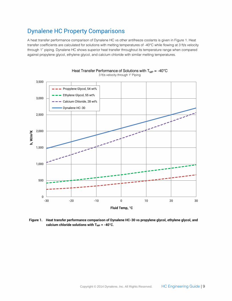
Dynalene HC Property Comparisons
A heat transfer performance comparison of Dynalene HC vs other antifreeze coolants is given in Figure 1. Heat
transfer coefficients are calculated for solutions with melting temperatures of -40°C while flowing at 3 ft/s velocity
through 1” piping. Dynalene HC shows superior heat transfer throughout its temperature range when compared
against propylene glycol, ethylene glycol, and calcium chloride with similar melting temperatures.
Figure 1. Heat transfer performance comparison of Dynalene HC-30 vs propylene glycol, ethylene glycol, and
calcium chloride solutions with TMP = -40°C.
0
500
1,000
1,500
2,000
2,500
3,000
3,500
-30 -20 -10 0 10 20 30
h,
W/m
2K
Fluid Temp, °C
Heat Transfer Performance of Solutions with TMP = -40°C3 ft/s velocity through 1" Piping
Propylene Glycol, 54 wt%
Ethylene Glycol, 55 wt%
Calcium Chloride, 28 wt%
Dynalene HC-30
Copyright © 2014 Dynalene, Inc. All Rights Reserved. HC Engineering Guide | 10
Dynalene HC -50 Properties
Thermophysical properties for Dynalene HC-50 are given in Tables 5a and 5b.
Table 5a. Dynalene HC-50 properties, SI units.
Viscosity Therm. Cond.
Specific Heat Density
°C mPa·s W/m·K kJ/kg·K kg/m3
-50 38.40 0.435 2.563 1378
-40 20.40 0.445 2.583 1373
-30 12.50 0.455 2.602 1367
-20 8.40 0.465 2.622 1362
-10 5.99 0.475 2.642 1356
0 4.70 0.485 2.661 1351
10 3.80 0.495 2.681 1345
20 3.20 0.505 2.701 1340
30 2.70 0.515 2.720 1334
40 2.40 0.525 2.740 1328
50 2.10 0.535 2.760 1323
60 1.80 0.545 2.780 1317
70 1.60 0.555 2.799 1312
80 1.50 0.565 2.819 1306
90 1.30 0.575 2.839 1301
100 1.20 0.585 2.858 1295
110 1.10 0.595 2.878 1290
120 1.00 0.605 2.898 1284
130 0.94 0.615 2.917 1279
140 0.87 0.625 2.937 1273
150 0.81 0.635 2.957 1267
160 0.76 0.645 2.977 1262
170 0.71 0.655 2.996 1256
180 0.66 0.665 3.016 1251
190 0.62 0.675 3.036 1245
200 0.58 0.685 3.055 1240
210 0.55 0.6945 3.075 1234
Table 5b. Dynalene HC-50 properties, English units.
Viscosity Therm. Cond.
Specific Heat Density
°F cP BTU/hr·ft·°F BTU/lb·°F lb/ft3
-58 38.40 0.256 0.612 85.9
-50 28.30 0.258 0.615 85.7
-40 20.40 0.262 0.617 85.6
-20 11.90 0.268 0.622 85.2
0 7.70 0.275 0.628 84.8
20 5.40 0.281 0.633 84.4
40 4.20 0.288 0.638 84.0
60 3.40 0.294 0.643 83.6
80 2.90 0.301 0.649 83.3
100 2.40 0.307 0.654 82.9
120 2.10 0.314 0.659 82.5
140 1.80 0.320 0.664 82.1
160 1.60 0.327 0.669 81.7
180 1.40 0.333 0.675 81.3
200 1.30 0.340 0.680 80.9
220 1.20 0.346 0.685 80.6
240 1.10 0.353 0.690 80.2
260 0.97 0.356 0.696 79.8
280 0.89 0.366 0.701 79.4
300 0.82 0.373 0.706 79.0
320 0.76 0.379 0.711 78.6
340 0.70 0.386 0.717 78.3
360 0.65 0.392 0.722 77.9
380 0.61 0.399 0.727 77.5
400 0.57 0.405 0.732 77.1
420 0.53 0.412 0.737 76.7
425 0.53 0.413 0.739 76.6
Copyright © 2014 Dynalene, Inc. All Rights Reserved. HC Engineering Guide | 11
Dynalene HC -40 Properties
Thermophysical properties for Dynalene HC-40 are given in Tables 6a and 6b.
Table 6a. Dynalene HC-40 properties, SI units.
Viscosity Therm. Cond.
Specific Heat Density
°C mPa·s W/m·K kJ/kg·K kg/m3
-40 14.90 0.449 2.80 1348
-30 9.20 0.459 2.82 1343
-20 6.50 0.469 2.84 1337
-10 4.90 0.479 2.87 1332
0 3.90 0.489 2.89 1326
10 3.20 0.499 2.91 1321
20 2.70 0.509 2.93 1315
30 2.30 0.519 2.96 1309
40 1.96 0.529 2.98 1304
50 1.70 0.539 3.00 1298
60 1.50 0.549 3.03 1293
70 1.40 0.559 3.05 1287
80 1.20 0.569 3.07 1281
90 1.10 0.579 3.09 1276
100 0.99 0.589 3.12 1270
110 0.91 0.599 3.14 1265
120 0.83 0.609 3.16 1259
130 0.77 0.619 3.19 1253
140 0.71 0.629 3.21 1248
150 0.66 0.639 3.23 1242
160 0.61 0.649 3.25 1237
165 0.59 0.654 3.27 1234
170 0.57 0.659 3.28 1231
180 0.53 0.669 3.30 1225
190 0.50 0.679 3.32 1220
200 0.47 0.689 3.35 1214
Table 6b. Dynalene HC-40 properties, English units.
Viscosity Therm. Cond.
Specific Heat Density
°F cP BTU/hr·ft·°F BTU/lb·°F lb/ft3
-40 14.90 0.264 0.669 84.0
-20 8.80 0.271 0.675 83.6
0 6.10 0.277 0.681 83.2
20 4.50 0.284 0.687 82.8
40 3.50 0.290 0.693 82.5
60 2.90 0.297 0.699 82.1
80 2.40 0.303 0.705 81.7
90 2.20 0.307 0.708 81.5
100 2.00 0.310 0.711 81.3
120 1.70 0.316 0.717 80.9
140 1.50 0.323 0.723 80.5
160 1.30 0.330 0.729 80.1
180 1.20 0.336 0.735 79.8
200 1.10 0.343 0.741 79.4
220 0.95 0.349 0.747 79.0
240 0.86 0.356 0.753 78.6
260 0.79 0.362 0.759 78.2
280 0.72 0.369 0.765 77.8
300 0.66 0.375 0.771 77.4
320 0.61 0.382 0.777 77.0
340 0.56 0.388 0.784 76.7
360 0.52 0.395 0.79 76.3
380 0.49 0.401 0.796 75.9
400 0.45 0.408 0.802 75.5
420 0.42 0.414 0.808 75.1
425 0.42 0.416 0.809 75.0
Copyright © 2014 Dynalene, Inc. All Rights Reserved. HC Engineering Guide | 12
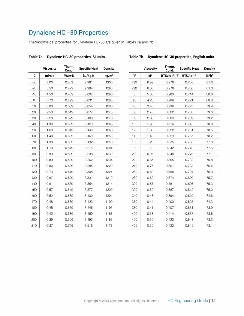
Dynalene HC -30 Properties
Thermophysical properties for Dynalene HC-30 are given in Tables 7a and 7b.
Table 7a. Dynalene HC-30 properties, SI units.
Viscosity Therm. Cond.
Specific Heat Density
°C mPa·s W/m·K kJ/kg·K kg/m3
-30 7.00 0.469 2.961 1300
-20 5.50 0.479 2.984 1295
-10 4.50 0.489 3.007 1290
0 3.70 0.499 3.031 1285
10 3.00 0.509 3.054 1280
20 2.50 0.519 3.077 1275
30 2.20 0.529 3.100 1270
40 1.90 0.539 3.123 1265
50 1.60 0.549 3.146 1260
60 1.40 0.559 3.169 1255
70 1.30 0.569 3.192 1250
80 1.10 0.579 3.215 1244
90 0.99 0.589 3.238 1239
100 0.89 0.599 3.262 1234
110 0.80 0.609 3.285 1229
120 0.73 0.619 3.308 1224
130 0.67 0.629 3.331 1219
140 0.61 0.639 3.354 1214
150 0.57 0.649 3.377 1209
160 0.52 0.659 3.400 1204
170 0.48 0.669 3.423 1199
180 0.45 0.679 3.446 1193
190 0.42 0.689 3.469 1188
200 0.39 0.699 3.493 1183
210 0.37 0.709 3.516 1178
Table 7b. Dynalene HC-30 properties, English units.
Viscosity Therm. Cond.
Specific Heat Density
°F cP BTU/hr·ft·°F BTU/lb·°F lb/ft3
-22 6.99 0.276 0.708 81.0
-20 6.80 0.276 0.708 81.0
0 5.30 0.283 0.714 80.6
20 4.20 0.289 0.721 80.3
40 3.40 0.296 0.727 79.9
60 2.70 0.302 0.733 79.6
80 2.30 0.309 0.739 79.2
100 1.90 0.316 0.745 78.9
120 1.60 0.322 0.751 78.5
140 1.40 0.329 0.757 78.2
160 1.20 0.335 0.763 77.8
180 1.10 0.342 0.770 77.5
200 0.95 0.348 0.776 77.1
220 0.85 0.355 0.782 76.8
240 0.76 0.361 0.788 76.4
260 0.69 0.368 0.794 76.0
280 0.62 0.374 0.800 75.7
300 0.57 0.381 0.806 75.3
320 0.52 0.387 0.812 75.0
340 0.48 0.394 0.819 74.6
360 0.44 0.400 0.825 74.3
380 0.41 0.407 0.831 73.9
400 0.38 0.414 0.837 73.6
420 0.36 0.420 0.843 73.2
425 0.35 0.422 0.845 73.1

Copyright © 2014 Dynalene, Inc. All Rights Reserved. HC Engineering Guide | 13
Dynalene HC -20 Properties
Thermophysical properties for Dynalene HC-20 are given in Tables 8a and 8b.
Table 8a. Dynalene HC-20 properties, SI units.
Viscosity Therm. Cond.
Specific Heat Density
°C mPa·s W/m·K kJ/kg·K kg/m3
-20 4.50 0.483 3.117 1258
-10 3.60 0.493 3.141 1253
0 3.00 0.503 3.164 1248
10 2.50 0.513 3.188 1242
20 2.10 0.523 3.212 1237
30 1.80 0.533 3.235 1232
40 1.60 0.543 3.259 1227
50 1.40 0.553 3.282 1222
60 1.20 0.563 3.306 1216
70 1.10 0.573 3.330 1211
80 0.95 0.583 3.353 1206
90 0.85 0.593 3.377 1201
100 0.77 0.603 3.400 1196
110 0.70 0.613 3.424 1191
120 0.63 0.623 3.448 1185
130 0.58 0.633 3.471 1180
140 0.54 0.643 3.495 1175
150 0.49 0.653 3.518 1170
160 0.46 0.663 3.542 1165
170 0.43 0.673 3.566 1159
180 0.40 0.683 3.589 1154
190 0.37 0.693 3.613 1149
200 0.35 0.703 3.636 1144
210 0.33 0.713 3.660 1139
Table 8b. Dynalene HC-20 properties, English units.
Viscosity Therm. Cond.
Specific Heat Density
°F cP BTU/hr·ft·°F BTU/lb·°F lb/ft3
-4 4.50 0.284 0.745 78.4
0 4.30 0.285 0.746 78.3
20 3.40 0.292 0.752 77.9
40 2.80 0.298 0.759 77.6
60 2.30 0.305 0.765 77.2
80 1.90 0.311 0.771 76.9
100 1.60 0.318 0.777 76.5
120 1.40 0.324 0.784 76.1
140 1.20 0.331 0.790 75.8
160 1.00 0.337 0.796 75.4
180 0.93 0.344 0.803 75.1
200 0.82 0.351 0.809 74.7
220 0.73 0.357 0.815 74.3
240 0.66 0.364 0.821 74.0
260 0.60 0.370 0.828 73.6
280 0.54 0.377 0.834 73.3
300 0.50 0.383 0.840 72.9
320 0.46 0.390 0.846 72.6
340 0.42 0.396 0.853 72.2
360 0.39 0.403 0.859 71.8
380 0.36 0.409 0.865 71.5
400 0.34 0.416 0.871 71.1
420 0.32 0.422 0.878 70.8
425 0.31 0.424 0.879 70.7
Copyright © 2014 Dynalene, Inc. All Rights Reserved. HC Engineering Guide | 14
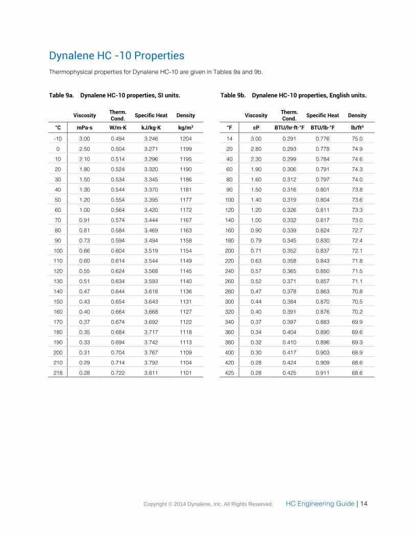
Dynalene HC -10 Properties
Thermophysical properties for Dynalene HC-10 are given in Tables 9a and 9b.
Table 9a. Dynalene HC-10 properties, SI units.
Viscosity Therm. Cond.
Specific Heat Density
°C mPa·s W/m·K kJ/kg·K kg/m3
-10 3.00 0.494 3.246 1204
0 2.50 0.504 3.271 1199
10 2.10 0.514 3.296 1195
20 1.80 0.524 3.320 1190
30 1.50 0.534 3.345 1186
40 1.30 0.544 3.370 1181
50 1.20 0.554 3.395 1177
60 1.00 0.564 3.420 1172
70 0.91 0.574 3.444 1167
80 0.81 0.584 3.469 1163
90 0.73 0.594 3.494 1158
100 0.66 0.604 3.519 1154
110 0.60 0.614 3.544 1149
120 0.55 0.624 3.568 1145
130 0.51 0.634 3.593 1140
140 0.47 0.644 3.618 1136
150 0.43 0.654 3.643 1131
160 0.40 0.664 3.668 1127
170 0.37 0.674 3.692 1122
180 0.35 0.684 3.717 1118
190 0.33 0.694 3.742 1113
200 0.31 0.704 3.767 1109
210 0.29 0.714 3.792 1104
218 0.28 0.722 3.811 1101
Table 9b. Dynalene HC-10 properties, English units.
Viscosity Therm. Cond.
Specific Heat Density
°F cP BTU/hr·ft·°F BTU/lb·°F lb/ft3
14 3.00 0.291 0.776 75.0
20 2.80 0.293 0.778 74.9
40 2.30 0.299 0.784 74.6
60 1.90 0.306 0.791 74.3
80 1.60 0.312 0.797 74.0
90 1.50 0.316 0.801 73.8
100 1.40 0.319 0.804 73.6
120 1.20 0.326 0.811 73.3
140 1.00 0.332 0.817 73.0
160 0.90 0.339 0.824 72.7
180 0.79 0.345 0.830 72.4
200 0.71 0.352 0.837 72.1
220 0.63 0.358 0.843 71.8
240 0.57 0.365 0.850 71.5
260 0.52 0.371 0.857 71.1
280 0.47 0.378 0.863 70.8
300 0.44 0.384 0.870 70.5
320 0.40 0.391 0.876 70.2
340 0.37 0.397 0.883 69.9
360 0.34 0.404 0.890 69.6
380 0.32 0.410 0.896 69.3
400 0.30 0.417 0.903 68.9
420 0.28 0.424 0.909 68.6
425 0.28 0.425 0.911 68.6
Copyright © 2014 Dynalene, Inc. All Rights Reserved. HC Engineering Guide | 15
Appendix
Notice to all System Operators
Dynalene HC is a non-toxic, high performance heat transfer fluid currently being used in this system. This product
will provide long life and low maintenance service in properly maintained systems. Also ask about our Engineering
Guide. Please practice the following procedures when handling or maintaining systems that contain Dynalene HC:
1. Do not use Dynalene HC in systems containing plated metals such as magnesium, zinc, or galvanized
metals.
2. To avoid degradation, metal surfaces exposed to air and wetted with Dynalene HC should be promptly
rinsed clean with water and dried.
3. To aid in obtaining leak-free pipe thread joints, it is recommended that ALL threads be clean and oil free
prior to assembly. Use a quality PTFE thread sealant, and then tightly wrap the entire thread surface area
with a minimum of three passes of PTFE tape. Cover the PTFE tape with a thin layer of PTFE-based pipe
dope and then proceed to assemble the threaded fitting. Flanged, welded or brazed joints are the
preferred sealing methods.
4. Use system components that are approved to operate with ionic fluids similar to Dynalene HC.
Consult the Dynalene engineering office at 1-610-262- 9686 (fax 1- 610-262-7437) for more information.
Toxicological Report
The following toxicological information on Dynalene HC heat transfer fluid are excerpts obtained from the “Detailed
Report” conducted by a 3rd party expert, Target Health Inc. (Dr. Jules T. Mitchell). Select proprietary information
has been omitted in this abbreviated report for the sole purpose of maintaining confidentiality on the product recipe.
More detailed information is available to qualified recipients. Please contact the Dynalene Engineering Department
at (610) 262-9686, fax (610) 262-7437 or through the Internet at www.dynalene.com, if you require additional
information.
1 Introduction
Dynalene HC is a heat transfer fluid used in food processing. Under normal conditions of use, the cooling
solution would not contact food, and thus human exposure is unlikely. It is nevertheless possible that an
unforeseen circumstance in the processing area might result in unintended contact with food, or that there
might be accidental exposure in the workplace. Therefore, an assessment of the toxicity of Dynalene HC
was undertaken. This safety assessment involved the following three steps:
Three non-clinical toxicology studies were conduct with Dynalene HC in order to characterize the
acute toxicity profile.
A literature review of the toxicity data of each of the components of Dynalene HC was conducted.
An overall assessment was made of the safety of the product.
2 Toxicity Data on Dynalene HC
Three acute toxicity studies, performed under contract by Sitek Research Laboratories, were conducted
using Dynalene HC. The studies evaluated:
Acute oral toxicity
Acute dermal toxicity
Dermal irritation potential
Copyright © 2014 Dynalene, Inc. All Rights Reserved. HC Engineering Guide | 16
All studies were performed under Good Laboratory Practice (GLP) standard:
United States Environmental Protection Agency Title 40 Code of Federal Regulations parts 160 and 792
Revised July 1, 1992.
Based on the data collected in animals, Dynalene HC did not product acute oral or dermal toxicity and was
not a skin irritant. “The limit doses” used in the toxicity studies were based on recommendations of
Hazardous Substances Labeling Act (HSLA), the Environmental Protection Agency (EPA) and the Food
and Drug Administration (FDA). Products that do not induce toxicity at the ‘limit doses” may be considered
non-toxic.
In the acute oral study, rats (n ¸ 5/sex) received a single oral dose of 5,000 mg/kg (the limit dose) and were
observed for 14 days (Cockerham 1999a). None of the rats died during the study and no advance clinical
signs were reported. The only finding noted at necropsy was the presence of small amorphous, fatty-like
deposits in the bladders of the five males. Similar findings were not noted in the females. A relationship to
treatment was neither proved nor disproved. Based on this data, the acute oral LD50 (lethal dose killing
50% of the animals) is greater than 5,000 mg/kg. It is concluded that Dynalene HC can be considered non-
toxic by the oral route and that no acute effects would be anticipated following accidental oral exposure.
In the acute dermal toxicity study, rabbits (in = 5/sex) received a single dermal dose of 2,000 mg/kg (the
limit dose) and were observed for 14 days (Cockerham 1999b). No treatment-related mortalities, clinical
signs or gross pathological changes were observed. The acute dermal LD50 was greater than 2,000
mg/kg. It is concluded that Dynalene HC can be considered non-toxic by the dermal route and that no skin
reactions would be anticipated following accidental dermal exposure.
The dermal irritation potential of Dynalene HC (0.5 ml) was examined in rabbits (n = 6 females) up to 72
hours post-dosing (Cockerham 1999C). No irritation occurred at any time. It is concluded that Dynalene HC
can be considered non-irritating to the skin.
3 Overall Safety Assessment
Based on the data collected in animals, Dynalene HC did not produce acute oral or dermal toxicity and
was not a skin irritant. The “limit doses” used in the toxicity studies were based on recommendations of the
Hazardous Substances labeling Act (HSLA), the Environmental protection Agency (EPA) and the Food and
Drug Administration (FDA). Products that do not induce toxicity at the "limit doses” may be considered non-
toxic. It is also concluded that Dynalene HC is unlikely to produce adverse effects after possible accidental
acute exposures. These conclusions are based on the:
Lack of toxic effects in a series of acute toxicity studies conducted Dynalene HC.
Minimal evidence of acute toxicity reported in the published literature on the components of
Dynalene HC.
While reports of long-term effects were noted [in the literature] for some of the components, the multiple or
lifetime doses [suspected of producing these long-term effects] are not an anticipated risk of Dynalene HC.
[One component (present in Dynalene HC at less than 0.5%) upon high, long-term dosing produced
equivocal evidence of carcinogenicity in rodents and weakly positive mutagenicity in an Ames test.
(Carcinogenicity: NTP: no, IARC: no, OSHA: no).] It is concluded that in the event of an accidental human
exposure to Dynalene HC, the material will not produce adverse effects.
All studies were performed under Good Laboratory Practice (GLP) standard: United States Environmental
Protection Agency Title 40 Code of Federal Regulations parts 160 and 792 Revised July 1, 1992 25.
Copyright © 2014 Dynalene, Inc. All Rights Reserved. HC Engineering Guide | 17
Product Disclaimer
The information contained in this entire Publication is presented in good faith at “No charge ” and is believed to be
correct as of the date indicated no representations or warranties are made as to its completeness or accuracy. The
information listed is supplied upon the condition that the persons receiving it will make their own determination as to
its suitability for their purposes prior to use. In no event will the seller be responsible for damages of any nature
whatsoever resulting from the use of, or reliance upon, this information or the product to which this information
refers. Nothing contained on this page is to be construed as a recommendation to use the product, process,
equipment or formulation in conflict with any patent. No representation or warranty, expressed or implied, is made
that the use of this product will not infringe any patent.
No representations or warranties, either expressed or implies, of merchantability, fitness for a particular purpose or
for any other nature are made with respect to the information, or the product to which the information refers.
Locations and Contact Information
Corporate Headquarters
Dynalene, Inc.
5250 West Coplay Road
Whitehall, PA 18052
USA
Phone: 610-262-9686 / 1-855-216-7639
Fax: 610-262-7437
Email: [email protected]
Website: www.dynalene.com
Midwest Location
648 Bennett Road
Elk Grove Village, IL 60007
USA
Phone: 1-855-216-7639
Fax: 847-228-2842
West Location
1701 S 5350 W
Salt Lake City, UT 84104
USA
Phone: 1-877-244-5525
Fax: 610-262-7437


