1 ISCORMA-3, Cleveland, Ohio, 19-23 September 2005 DYNAMIC ANALYSIS OF A TURBOCHARGER IN FLOATING BUSHING BEARINGS Edgar J. Gunter RODYN VIBRATION ANALYSIS, INC. 1932 Arlington Blvd., Suite 223 Charlottesville, VA 22903 [email protected]Wen Jeng Chen Eigen Technology, Inc. P.O. Box 2224 Davidson, NC 28036 [email protected]ABSTRACT This paper presents the linear and nonlinear dynamical behavior of a typical turbocharger in floating bush bearings. In this paper, the linearized stability of the system was computed for various bushing inner and outer clearance ratios. The turbocharger has two principal modes in which it can exhibit whirl instability. The first is a conical mode which is essentially a rigid body mode. The second mode is an in-phase whirling mode in which over 50% of the system strain energy is associated with shaft bending. These whirling modes may be only 1/6 and 1/4 of running speed. Experimental data indicates that either one or both of these modes may exist simultaneously. Although the turbocharger exhibits self excited bearing instability at very low onset speeds, the turbocharger is able to operate with controlled limit cycle motion at speeds of 100,000 RPM and higher due to the nonlinear action of the fluid film floating bush bearings. In order to examine limit cycle motion, the system finite element dynamical equations of motion were numerically integrated forward in time. Included also in the analysis are the effects of rotor unbalance and destabilizing Alford type forces acting at the compressor and turbine wheels. These effects can strongly influence the limit cycle orbits and the bearing forces transmitted. The rotor could be made to whirl in either the first conical mode or the second in-phase mode by changes in the compressor or turbine bushing bearing clearances. A third bending critical speed was evaluated for unbalance response. This third mode may occur at peak speeds and may limit the maximum operating speed due to the high compressor bearing forces encountered and subsequent shaft bending. Keywords: turbocharger, stability, limit cycle motion, rotor whirling, time transient rotor dynamics Dyrobes Rotordynamics Software https://dyrobes.com
Transcript
1
ISCORMA-3, Cleveland, Ohio, 19-23 September 2005
DYNAMIC ANALYSIS OF A TURBOCHARGER IN FLOATINGBUSHING BEARINGS
Edgar J. GunterRODYN VIBRATION ANALYSIS, INC.
1932 Arlington Blvd., Suite 223Charlottesville, VA 22903
ABSTRACTThis paper presents the linear and nonlinear dynamical behavior of a typical turbocharger
in floating bush bearings. In this paper, the linearized stability of the system was computed forvarious bushing inner and outer clearance ratios. The turbocharger has two principal modes inwhich it can exhibit whirl instability. The first is a conical mode which is essentially a rigid bodymode. The second mode is an in-phase whirling mode in which over 50% of the system strainenergy is associated with shaft bending. These whirling modes may be only 1/6 and 1/4 of runningspeed. Experimental data indicates that either one or both of these modes may exist simultaneously.Although the turbocharger exhibits self excited bearing instability at very low onset speeds, theturbocharger is able to operate with controlled limit cycle motion at speeds of 100,000 RPM andhigher due to the nonlinear action of the fluid film floating bush bearings. In order to examine limitcycle motion, the system finite element dynamical equations of motion were numerically integratedforward in time. Included also in the analysis are the effects of rotor unbalance and destabilizingAlford type forces acting at the compressor and turbine wheels. These effects can strongly influencethe limit cycle orbits and the bearing forces transmitted. The rotor could be made to whirl in eitherthe first conical mode or the second in-phase mode by changes in the compressor or turbine bushingbearing clearances.
A third bending critical speed was evaluated for unbalance response. This third mode mayoccur at peak speeds and may limit the maximum operating speed due to the high compressorbearing forces encountered and subsequent shaft bending.
INTRODUCTIONThe dynamical analysis of a turbocharger represents a number of challenging problems. The
typical turbocharger is often referred to as a double overhung rotor. That is, the turbine andcompressor wheels are outboard of the bearings. These turbochargers can operate in a speed rangeexceeding 100,000 RPM. The type of bearing and damper design for a turbocharger is dictated byits size and performance capabilities. For example, a large turbocharger for a diesel locomotive mayhave a 3 lobe or offset bearing supported in a centered squeeze-film damper. These elaboratebearing designs are not possible in the smaller turbochargers that are used in automotive applicationsdue to size and cost considerations. A standard type of bearing employed with automotiveturbochargers is the floating bush bearing. Turbocharger Design With Floating Bushing Bearings
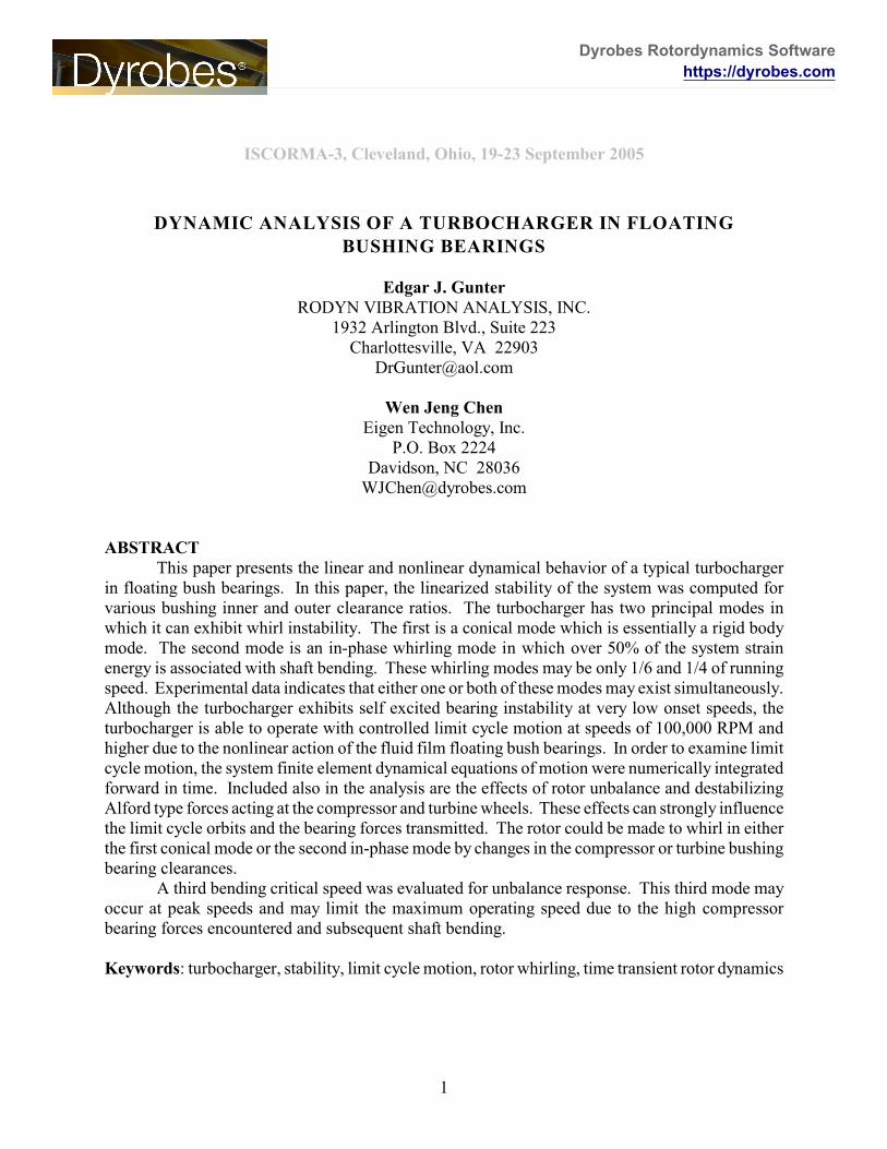
Fig. 1 represents a schematic drawing of a typical turbocharger as presented by Li (1982).The figure of Li has been modified to show the floating bushing bearings.
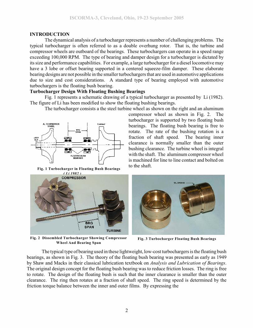
The turbocharger consists a the steel turbine wheel as shown on the right and an aluminumcompressor wheel as shown in Fig. 2. Theturbocharger is supported by two floating bushbearings. The floating bush bearing is free torotate. The rate of the bushing rotation is afraction of shaft speed. The bearing innerclearance is normally smaller than the outerbushing clearance. The turbine wheel is integralwith the shaft. The aluminum compressor wheelis machined for line to line contact and bolted onto the shaft.
The typical type of bearing used in these lightweight, low-cost turbochargers is the floating bushbearings, as shown in Fig. 3. The theory of the floating bush bearing was presented as early as 1949by Shaw and Macks in their classical lubrication textbook on Analysis and Lubrication of Bearings.The original design concept for the floating bush bearing was to reduce friction losses. The ring is freeto rotate. The design of the floating bush is such that the inner clearance is smaller than the outerclearance. The ring then rotates at a fraction of shaft speed. The ring speed is determined by thefriction torque balance between the inner and outer films. By expressing the
Fig. 1 Turbocharger in Floating Bush Bearings
( Li 1982 )
Fig. 2 Dissembled Turbocharger Showing Compressor
Wheel And Bearing Span Fig. 3 Turbocharger Floating Bush Bearings
ISCORMA-3, Cleveland, Ohio, 19-23 September 2005
3
Reynolds equation governing the pressure profile in rotating coordinates, Shaw and Macks explain themechanism by which the floating bush bearing generates a pressure profile as a combination of ringrotation, ring precession rate, and radial squeeze film motion..
The pressure profile is generated by the rotational speed of the ring, its precessional rate, andits local eccentricity velocity. For circular orbiting about the origin, this last term may be ignored. Themodeling of the floating bush bearing can become quite extensive, and the analysis is assisted byexperimental data. One of the major problems in the analysis of the floating bush is the assumptionof the ring speed. Theoretically, one could have a ring speed approaching one-half of shaft rotation,but this value never occurs in practice. Quite often, what is observed is a uniform increase in ring speedas a percentage of shaft speed until, at given speed, the ring speed is constant. In this analysis, ringspeed was assumed to be 20% of shaft speed although Li measured values as low as 11%. Detailedanalysis of the ring, including thermal effects, show that the inner temperature can be substantiallyhigher than the outer film temperature. The high inner temperature reduces the viscosity and causesa limit of the speed of rotation of the ring.
The floating bush ring is commonly employed because it is inexpensive to produce. However,with a fixed journal bearing, the stability is extremely poor as compared to a lobed or tilting-padbearing. The rotation of the outer surface of the floating bush bearing acts as an uncentered squeeze-film damper. The analysis is difficult because, even with the assumption of ring speed, the system isnonlinear. One can, however, perform a linearized analysis to determine the stiffness and dampingcoefficients of both the inner and outer clearances. The linearized stability analysis shows that thesystem is unstable at speeds of 100,000 RPM. In fact, the onset speed can be extremely low. Inaddition to being unstable, the instability can be exhibited in either the first mode, which has a conicalmode shape, or in the second mode, which involves shaft bending. The earlier analysis of Li (1982)did not have enough degrees of freedom to show the second unstable mode or the rotor third bendingcritical speed. Experimental Turbocharger Whirl Motion
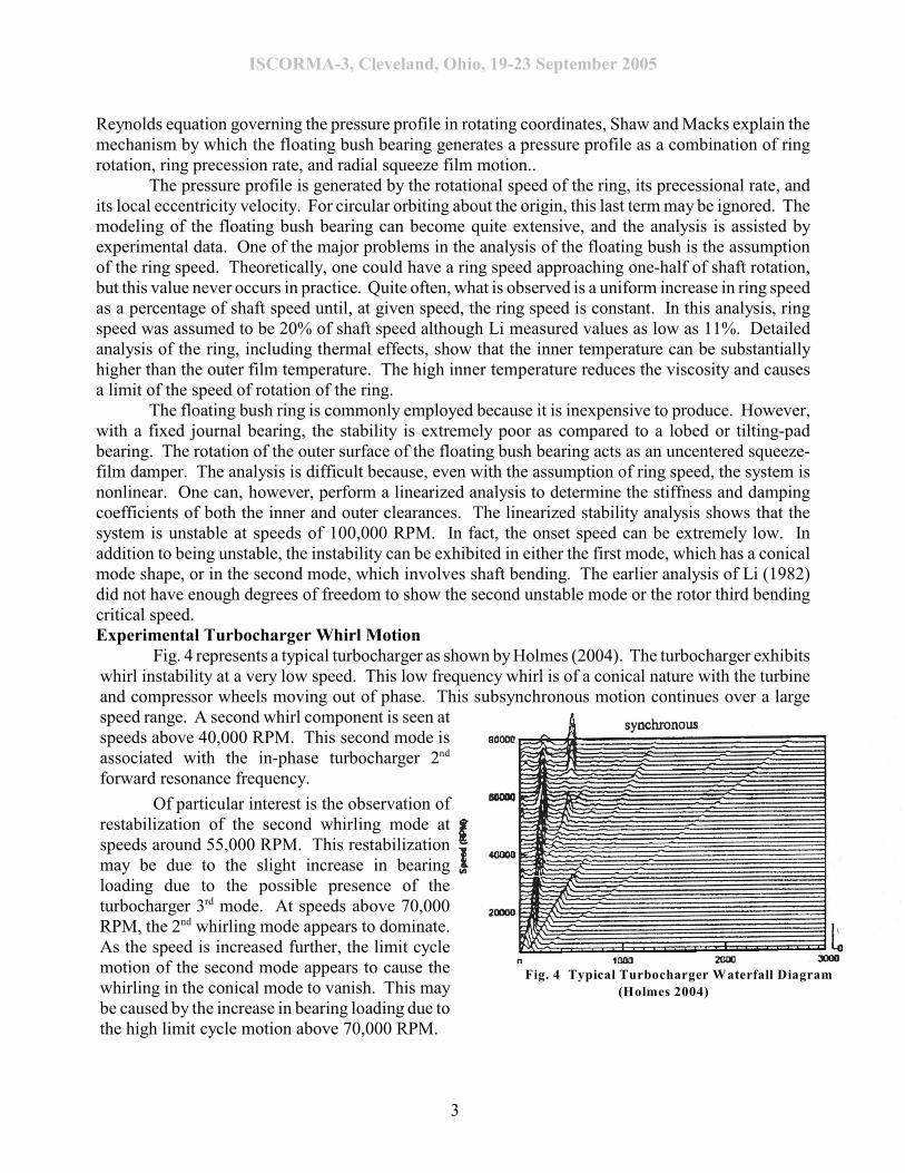
Fig. 4 represents a typical turbocharger as shown by Holmes (2004). The turbocharger exhibitswhirl instability at a very low speed. This low frequency whirl is of a conical nature with the turbineand compressor wheels moving out of phase. This subsynchronous motion continues over a largespeed range. A second whirl component is seen atspeeds above 40,000 RPM. This second mode isassociated with the in-phase turbocharger 2nd
forward resonance frequency.
Of particular interest is the observation ofrestabilization of the second whirling mode atspeeds around 55,000 RPM. This restabilizationmay be due to the slight increase in bearingloading due to the possible presence of theturbocharger 3 mode. At speeds above 70,000rd
RPM, the 2 whirling mode appears to dominate.nd
As the speed is increased further, the limit cyclemotion of the second mode appears to cause thewhirling in the conical mode to vanish. This maybe caused by the increase in bearing loading due tothe high limit cycle motion above 70,000 RPM.
Fig. 4 Typical Turbocharger Waterfall Diagram
(Holmes 2004)
ISCORMA-3, Cleveland, Ohio, 19-23 September 2005
4
Although the floating bush bearing may be unstable in the linear sense, when a nonlinear timetransient analysis is performed, then limit cycle whirl motion is observed. This limit cycle whirlmotion is a bounded motion, and the turbocharger may operate for an extended time with boundedlimit cycle whirl motion. There is the added paradox that rotating unbalance load may actually resultin a lower limit cycle whirl motion than a well-balanced rotor. In this paper, a typical turbochargerin floating bush bearings is analyzed for nonlinear transient motion with various clearance conditionsand unbalances. In addition to the problems of limit cycle whirl motion, which may be quite largeunder certain circumstances, there is an additional problem that can be encountered with turbochargers.As designs are attempted to run over 100,000 RPM, then certain turbochargers are encountering thethird flexible critical speed. This mode is very difficult to balance out and may have a highamplification factor leading to rubbing and bearing distress.
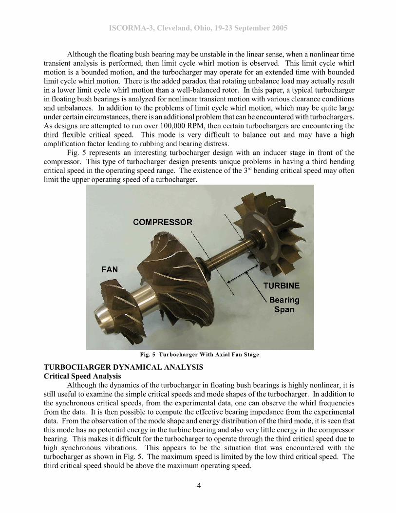
Fig. 5 represents an interesting turbocharger design with an inducer stage in front of thecompressor. This type of turbocharger design presents unique problems in having a third bendingcritical speed in the operating speed range. The existence of the 3 bending critical speed may oftenrd
limit the upper operating speed of a turbocharger.
Although the dynamics of the turbocharger in floating bush bearings is highly nonlinear, it isstill useful to examine the simple critical speeds and mode shapes of the turbocharger. In addition tothe synchronous critical speeds, from the experimental data, one can observe the whirl frequenciesfrom the data. It is then possible to compute the effective bearing impedance from the experimentaldata. From the observation of the mode shape and energy distribution of the third mode, it is seen thatthis mode has no potential energy in the turbine bearing and also very little energy in the compressorbearing. This makes it difficult for the turbocharger to operate through the third critical speed due tohigh synchronous vibrations. This appears to be the situation that was encountered with theturbocharger as shown in Fig. 5. The maximum speed is limited by the low third critical speed. Thethird critical speed should be above the maximum operating speed.
Fig. 5 Turbocharger With Axial Fan Stage
ISCORMA-3, Cleveland, Ohio, 19-23 September 2005
5
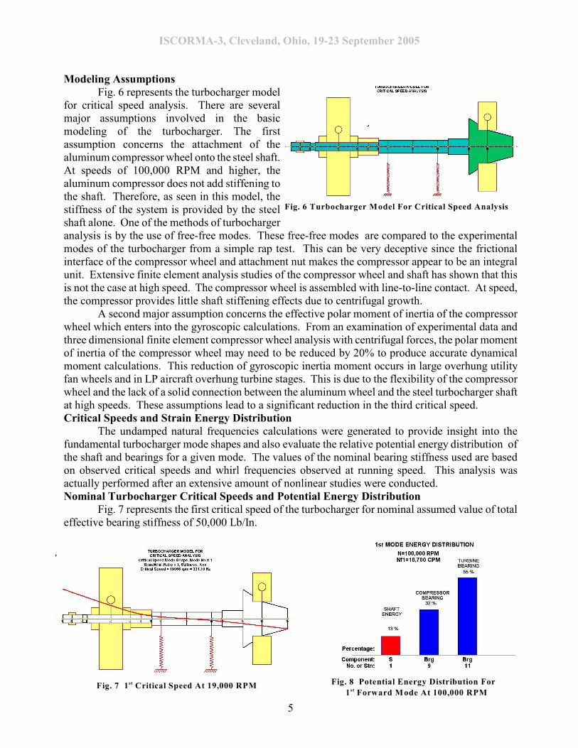
Modeling AssumptionsFig. 6 represents the turbocharger model
for critical speed analysis. There are severalmajor assumptions involved in the basicmodeling of the turbocharger. The firstassumption concerns the attachment of thealuminum compressor wheel onto the steel shaft.At speeds of 100,000 RPM and higher, thealuminum compressor does not add stiffening tothe shaft. Therefore, as seen in this model, thestiffness of the system is provided by the steelshaft alone. One of the methods of turbochargeranalysis is by the use of free-free modes. These free-free modes are compared to the experimentalmodes of the turbocharger from a simple rap test. This can be very deceptive since the frictionalinterface of the compressor wheel and attachment nut makes the compressor appear to be an integralunit. Extensive finite element analysis studies of the compressor wheel and shaft has shown that thisis not the case at high speed. The compressor wheel is assembled with line-to-line contact. At speed,the compressor provides little shaft stiffening effects due to centrifugal growth.
A second major assumption concerns the effective polar moment of inertia of the compressorwheel which enters into the gyroscopic calculations. From an examination of experimental data andthree dimensional finite element compressor wheel analysis with centrifugal forces, the polar momentof inertia of the compressor wheel may need to be reduced by 20% to produce accurate dynamicalmoment calculations. This reduction of gyroscopic inertia moment occurs in large overhung utilityfan wheels and in LP aircraft overhung turbine stages. This is due to the flexibility of the compressorwheel and the lack of a solid connection between the aluminum wheel and the steel turbocharger shaftat high speeds. These assumptions lead to a significant reduction in the third critical speed.Critical Speeds and Strain Energy Distribution
The undamped natural frequencies calculations were generated to provide insight into thefundamental turbocharger mode shapes and also evaluate the relative potential energy distribution ofthe shaft and bearings for a given mode. The values of the nominal bearing stiffness used are basedon observed critical speeds and whirl frequencies observed at running speed. This analysis wasactually performed after an extensive amount of nonlinear studies were conducted.Nominal Turbocharger Critical Speeds and Potential Energy Distribution
Fig. 7 represents the first critical speed of the turbocharger for nominal assumed value of totaleffective bearing stiffness of 50,000 Lb/In.
Fig. 6 Turbocharger Model For Critical Speed Analysis
Fig. 8 Potential Energy Distribution For
1 Forward Mode At 100,000 RPMstFig. 7 1 Critical Speed At 19,000 RPMst
ISCORMA-3, Cleveland, Ohio, 19-23 September 2005
6
The first mode is essentially a rigid body conical mode in which the turbine and compressor wheelsare out of phase. Fig. 8 represents the relative potential shaft and bearing energy distributions. Forthe first mode, the potential energy is greatest in the turbine bearing. This is due to the heavier weightof the turbine wheel. Thus the turbine bearing will have a greater control over the first critical speedand the conical whirl instability encountered at higher speeds.
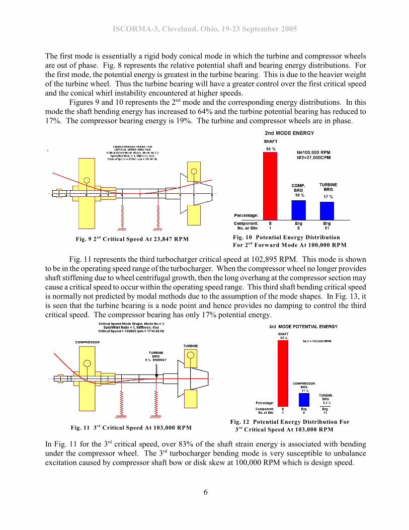
Figures 9 and 10 represents the 2 mode and the corresponding energy distributions. In thisnd
mode the shaft bending energy has increased to 64% and the turbine potential bearing has reduced to17%. The compressor bearing energy is 19%. The turbine and compressor wheels are in phase.
Fig. 11 represents the third turbocharger critical speed at 102,895 RPM. This mode is shownto be in the operating speed range of the turbocharger. When the compressor wheel no longer providesshaft stiffening due to wheel centrifugal growth, then the long overhang at the compressor section maycause a critical speed to occur within the operating speed range. This third shaft bending critical speedis normally not predicted by modal methods due to the assumption of the mode shapes. In Fig. 13, itis seen that the turbine bearing is a node point and hence provides no damping to control the thirdcritical speed. The compressor bearing has only 17% potential energy.
In Fig. 11 for the 3 critical speed, over 83% of the shaft strain energy is associated with bendingrd
under the compressor wheel. The 3 turbocharger bending mode is very susceptible to unbalancerd
excitation caused by compressor shaft bow or disk skew at 100,000 RPM which is design speed.
Fig. 10 Potential Energy Distribution
For 2 Forward Mode At 100,000 RPM ndFig. 9 2 Critical Speed At 23,847 RPMnd
Fig. 11 3 Critical Speed At 103,000 RPMrdFig. 12 Potential Energy Distribution For
3 Critical Speed At 103,000 RPMrd
ISCORMA-3, Cleveland, Ohio, 19-23 September 2005
7
Turbocharger Damped Natural Frequencies (Complex Eigenvalues)Fig. 13 represents the turbocharger model with the floating bushing bearings added. Two
additional bearing stations have been added in order to assign values of aerodynamic cross couplingacting at the turbine and compressor stations. Fig. 14 represents the specification of the floatingbushing characteristics such as clearances, film viscosities and ring spin speed ratio. The inner ringdiametral clearance Cdi is 2 mils and the outer ring clearance Cdo is taken as 4 mils.
Fig. 15 shows the first forward whirl mode at 100,000 RPM with a small amount ofaerodynamic cross-coupling of 100 Lb/In acting at both the compressor and turbine wheels. The whirlmode is essentially a rigid body conical mode with the turbine end bearing having the predominanteffect. Fig. 16 shows the second forward mode at 100,000 RPM. In this case, there is substantial shaftbending with the largest motion at the compressor end. This mode is only marginally stable as the logdecrement is only 0.022. This mode may also become unstable.
For the first conical mode as shown in Fig. 15, the turbine bearing has the most influence. Thestability in this mode is improved by a reduction of clearance in the turbine bearing. It is usually notpractical to close the turbine bearing up too tightly as there are cases of the ring welding on to theshaft. For the in-phase second whirl mode as shown in Fig. 16, the compressor end bearing has moreinfluence then the turbine end bearing. An increase of inner ring clearance on the compressor bearingmay induce the second whirling mode.
Fig. 13 Turbocharger Model With Floating Bush
Bearings And Aerodynamic Cross Coupling Fig. 14 Characteristics of Floating Bush Bearing
Fig. 15 Unstable Forward Conical Mode At 100,000 RPM
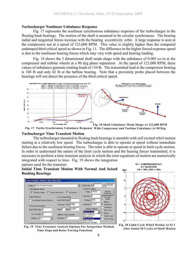
Turbocharger Nonlinear Unbalance ResponseFig. 17 represents the nonlinear synchronous unbalance response of the turbocharger in the
floating bush bearings. The motion of the shaft is assumed to be circular synchronous. The bearingradial and tangential forces increase with the bearing eccentricity orbit. A large response is seen atthe compressor nut at a speed of 123,000 RPM. This value is slightly higher than the computedundamped third critical speed as shown in Fig. 11. The difference in the higher forced response speedis due to the nonlinear bearing forces which may vary with speed and bearing loading.
Fig. 18 shows the 3 dimensional shaft mode shape with the unbalance of 0.005 oz-in at thecompressor and turbine wheels at a 90 deg phase separation. At the speed of 123,000 RPM, thesevalues of unbalance generate rotating loads of 134 lb. The transmitted load at the compressor bearingis 160 lb and only 62 lb at the turbine bearing. Note that a proximity probe placed between thebearings will not detect the presence of the third critical speed.
Turbocharger Time Transient MotionThe turbocharger mounted in floating bush bearings is unstable with self excited whirl motion
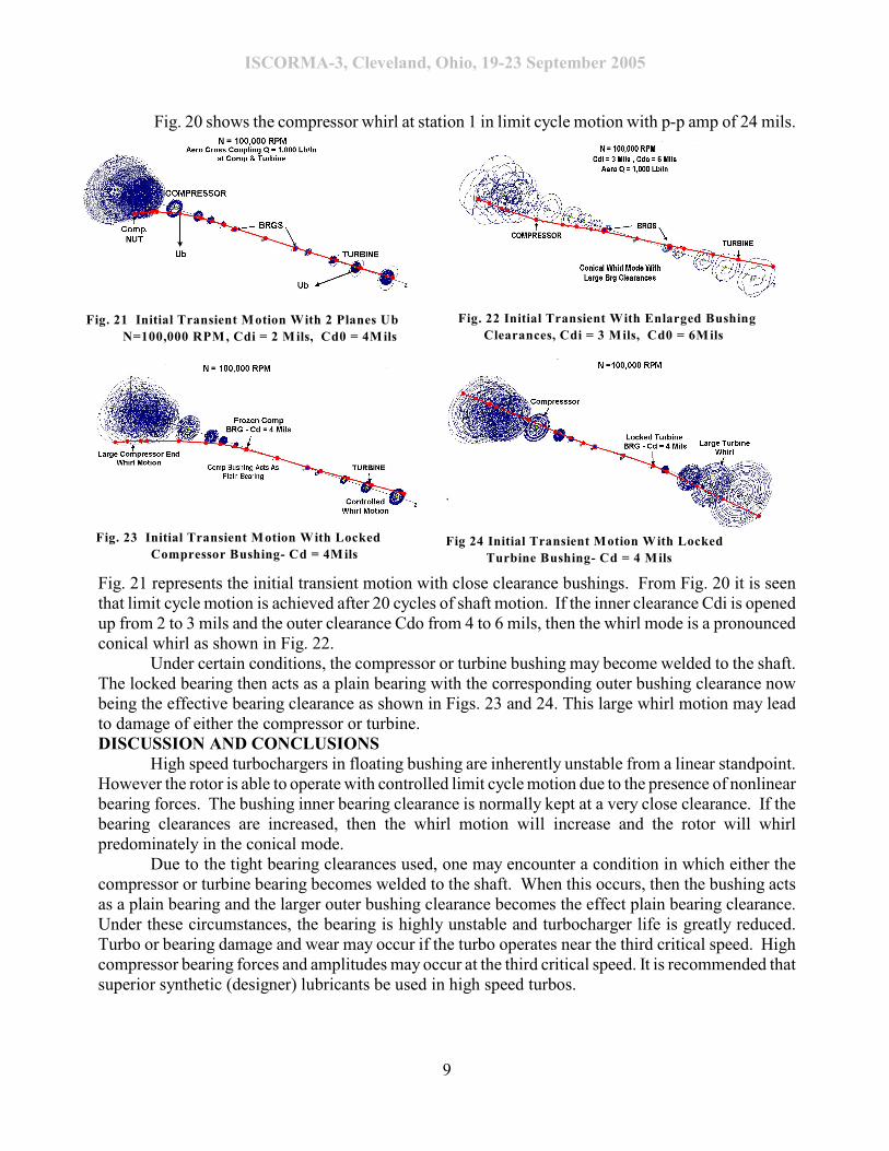
starting at a relatively low speed. The turbocharger is able to operate at speed without immediatefailure due to the nonlinear bearing forces. The rotor is able to operate at speed in limit cycle motion.In order to understand the nature of the limit cycle motion and the bearing forces transmitted, it isnecessary to perform a time transient analysis in which the rotor equations of motion are numericallyintegrated with respect to time. Fig. 19 shows the integrationoptions used for the transient.Initial Time Transient Motion With Normal And SeizedBushing Bearings.
After Initial 20 Cycles of Shaft Motion Fig. 19 Time Transient Analysis Options For Integration Method,
Time Steps and Rotor Forcing Functions
ISCORMA-3, Cleveland, Ohio, 19-23 September 2005
9
Fig. 20 shows the compressor whirl at station 1 in limit cycle motion with p-p amp of 24 mils.
Fig. 21 represents the initial transient motion with close clearance bushings. From Fig. 20 it is seenthat limit cycle motion is achieved after 20 cycles of shaft motion. If the inner clearance Cdi is openedup from 2 to 3 mils and the outer clearance Cdo from 4 to 6 mils, then the whirl mode is a pronouncedconical whirl as shown in Fig. 22.
Under certain conditions, the compressor or turbine bushing may become welded to the shaft.The locked bearing then acts as a plain bearing with the corresponding outer bushing clearance nowbeing the effective bearing clearance as shown in Figs. 23 and 24. This large whirl motion may leadto damage of either the compressor or turbine.DISCUSSION AND CONCLUSIONS
High speed turbochargers in floating bushing are inherently unstable from a linear standpoint.However the rotor is able to operate with controlled limit cycle motion due to the presence of nonlinearbearing forces. The bushing inner bearing clearance is normally kept at a very close clearance. If thebearing clearances are increased, then the whirl motion will increase and the rotor will whirlpredominately in the conical mode.
Due to the tight bearing clearances used, one may encounter a condition in which either thecompressor or turbine bearing becomes welded to the shaft. When this occurs, then the bushing actsas a plain bearing and the larger outer bushing clearance becomes the effect plain bearing clearance.Under these circumstances, the bearing is highly unstable and turbocharger life is greatly reduced.Turbo or bearing damage and wear may occur if the turbo operates near the third critical speed. Highcompressor bearing forces and amplitudes may occur at the third critical speed. It is recommended thatsuperior synthetic (designer) lubricants be used in high speed turbos.
Compressor Bushing- Cd = 4MilsFig 24 Initial Transient Motion With Locked
Turbine Bushing- Cd = 4 Mils
ISCORMA-3, Cleveland, Ohio, 19-23 September 2005
10
REFERENCES1 Alford, J., “Protecting Turbomachinery from Self-Excited Rotor Whirl”, ASME Journal of
Engineering for Power, pp. 333-337, 1965.2. Barrett, L. E., and E. J. Gunter, Steady-State and Transient Analysis of a Squeeze Film Damper
Bearing for Rotor Stability, NASA CR-2548, 1975.3. Chen, W. J., and E. J. Gunter, “Introduction to Dynamics of Rotor-Bearing Systems”
TRAFFORD Publishing, Victoria, BC, Canada, 2005.4. Dworski, J., “High-Speed Rotor Suspension Formed by Fully Floating Hydrodynamic Radial
and Thrust Bearings, “ASME Journal of Engineering for Power, Vol. 86, pp. 149-160, 1964.5. Gunter, E. J., and W. J. Chen, “DyRoBeS Dynamics of Rotor-Bearing Systems, Windows
Version 8, Users’ Manual, RODYN Vibration Analysis, Inc., Charlottesville, VA., 2003.6. Hill, H. C., “Slipper Bearings and Vibration Control in Small Gas Turbines,” ASME, Vol 80,
pp. 1756-1764, 1958.7. Holmes, R., “Turbocharger Vibrations - Case Study,” Institute of Mechanical Engineering
Conference on Turbochargers and Turbocharging, pp. 91-100, 2002.8. Holmes, R., “Vibrations of An Automotive Turbocharger - A Case Study,” C623, Institute of
Mechanical Engineering, pp. 445-450, 2004.9. Kettleborough, C. F., “Frictional Experiments on Lightly-Loaded Fully Floating Journal
Bearings,” Australian Journal of Applied Science, pp. 211-220, 1955.10. Kirk, R. G. and E. J. Gunter, “Nonlinear Transient Analysis of Multi-Mass Flexible Rotors -
Theory and Applications,” NASA CR-2300, NASA, Washington, D.C, 1973.11. Li, C. H., “On the Steady State and Dynamic Performance Characteristics of Floating Ring
Bearings,” Trans. ASME Journal of Lubrication Technology, Vol 103, pp. 389-397, 1981.12. Li, C. H., “Dynamics of Rotor Bearing System Supported by Floating Ring Bearings,” Trans.
ASME Journal of Lubrication Technology, Vol 104, pp. 469-477, 1982.13. Nakagawa, E., and H. Aoki, 1973, “Unbalance Vibration of a Rotor-Bearing System Supported
by Floating-Ring Journal Bearings,” Bull. ASME, Vol 16, 93, pp. 503-512.14. Nikolajsen, J. L., “The Effect of Variable Viscosity on the Stability of Plain Journal Bearings
and Floating-Ring Journal Bearings,” ASME Paper 73-Lub-H, 1973.15. Rohde, S. M. and H. A. Ezzat, “Analysis of Dynamically Loaded Floating-Ring Bearings for
Automotive Application,” Trans. ASME Journal of Lubrication Technology, Vol. 102, pp. 271-277, 1980.
16. Shaw, M. C. and T. J. Nussdorfer, “An Analysis of the Full-Floating Journal Bearing,” NACAReport No. 866, 1947.
17. Shaw, M. C. and F. Mack, Analysis And Lubrication Of Bearings, McGraw-Hill, New York,1949.
18. Tanaka, M. and Y. Hori, “Stability Characteristics of Floating Bush Bearings,” ASME Journalof Lubrication Technology, Vol 94, pp. 248-259, 1972.
19. Tartara, A., “An Experimental Study of the Stabilizing Effect of Floating-Bush JournalBearings,” Bull. ASME, Vol 13, 61, pp. 858-863 , 1972.
20. Trippett, R. J. and D. F. Li, “High Speed Floating-Ring Bearing Test and Analysis,” ASMETrans., Vol 27, pp. 73-81, 1983.