Dynamic Analysis of Tubular Systems in Tall Buildings
Palak Joshi1, Roshni John2
1ME Student, Dept. of Civil Engineering, Saraswati College of Engineering, Kharghar, Maharashtra, India 2Associate Professor, Dept. of Civil Engineering, Saraswati College of Engineering, Kharghar, Maharashtra, India
Abstract - While the world is full of fascinating structures, the most eye-catching and the ones that instil the greatest sense of wonder in the onlooker are the modern skyscrapers. They are monuments of power and prestige, supreme achievements in engineering and design, comforting landmarks, testimonials to the human spirit, and public relations at the highest level. As the population density of urban areas has amplified, so has the need for buildings that rise rather than spread. In the present study, four configurations are considered: Framed Tube, Tube in Tube, Bundled Tube and Moment Resisting Frame with Shear Wall Core. The analysis is carried out for tall 60 storied structures located in Seismic Zone IV for medium soil condition. Analysis is performed by Response Spectrum method and Wind Load calculation by Gust Factor method. The dynamic response of these structures in terms of Storey Displacement, Storey Drift, Base Shear and Fundamental Time Period is presented and compared within the considered configuration as well as a suitable configuration of the building is suggested for structural stability.
Key Words: Tall Buildings, Framed Tube, Tube in Tube, Bundled Tube, Response Spectrum Method, Moment Resisting Frame, Shear Wall, Storey Displacement, Storey Drift, Base Shear, Time Period
1.INTRODUCTION In the tall building design, the tube system is one of the common lateral stability systems. The tube system was innovated in the early 1960s by the famous structural engineer Fazlur Rahman Khan from the firm Skidmore, Owings & Merrill (SOM). The tube system can be likened to a system in which a hollow box column is cantilevering from the ground. This allows to create an indefinite stiff “shell” around the building exterior and so the building exterior exhibits a tubular behaviour against lateral loads. This system is evolved from the rigid frame system and can be defined as a three-dimensional rigid frame having the capability of resisting all lateral loads with the facade structure. It was an innovative lateral stability system for designing a taller, more efficient building at that time. It has dramatic difference compared to the traditional structural system for multi-storey buildings, such as frame system, core wall strengthened by outrigger, etc.
1.1 Framed Tube
The framed tube systems, which constitute the basis of tube systems, can be described as having evolved from rigid frame systems and are alternative to shear frame systems.
The most significant feature of the system, also known as the “Vierendeel” tube system” or “perforated tube system”, is the closely spaced perimeter/exterior columns, which are usually spaced at 1.5 to 4.5m centres, connected by deep spandrel beams at floor levels. If there is a need to increase the column spacing, in order to secure the behaviour of the framed tube system, it is necessary to increase the dimensions of the perimeter columns and spandrel beams.
1.2 Tube in Tube
When the building plan is large, sometimes, many columns may be required to support the gravity loads. Then, it may be beneficial to create a second tube of columns interconnected with beams inside the perimeter tube of columns interconnected with beams. This system is called the Tube in Tube System.
In the Tube in Tube system, the tubes should be tied together with a stiff and strong grid of beams. Depending on the total load to be transferred, the spacing of the gravity as well as main frame columns need to be adjusted – closely spaced columns with center-to-center spacing even up to 2m are used. This also helps in uniform distribution of forces to the perimeter tube columns. If the distance between the two tubes is large, intermediate secondary beams, along with additional gravity columns, may become necessary for effectively transferring lateral forces to the tubes; the additional gravity columns keep the intermediate beams from deflecting too much and thereby make them capable of transferring axial compression without much out-of-plane deformation. More uniform distribution of gravity forces is achieved with closely spaced beam grids between the tubes.
1.3 Bundled Tube
Bundled tube systems are a combination of more than one tube (framed tube and/or trussed tube) acting together as a single tube. In the bundled tube system, setbacks with floor plans of different shapes and dimensions are obtained by ending tubes at the desired levels. Single tubes in the system can be arranged together in different shapes such as rectangles and triangles, and thus different forms can be created.
In bundled tube systems, the increase in the cross-sectional dimensions at the ground floor in order to control the slenderness of the building makes it possible to reduce the cross-sectional dimensions by different amounts throughout the height of the building. In bundled tube systems formed from framed tubes and/or trussed tubes, greater building heights and wider column spaces are obtained than in framed tube systems.
International Research Journal of Engineering and Technology (IRJET) e-ISSN: 2395-0056
Volume: 08 Issue: 11 | Nov 2021 www.irjet.net p-ISSN: 2395-0072
2. LITERATURE REVIEW N. Khanna, et al. (2019) [1] presented a 50 storied moment frame, moment frame with shear wall at corners, moment frame with central core, framed tube system, tube-in-tube system, outrigger system and outrigger with belt truss. The structures were considered to be located in Seismic zone IV and the dynamic analysis was done by Response Spectrum Method. They studied the results on parameters Maximum Storey Displacement, Base Shear and Time Period. They found that the outrigger system was more efficient and outrigger with belt truss was more stable and rigid.
M. Eadukondalu, et al. (2018) [2] presented a plain frame system, shear wall system and framed tube system of 30, 40, 50 and 60 storeys. The structures were considered to be located in Seismic zone II. They studied the results on parameters Support Reactions, Lateral Displacement and Base Shear. They found that the shear wall system was best suitable for 30 storey structure as the lateral roof displacement had a difference of nearly 2% only and it was economical whereas for the 40, 50 and 60 storey structures, the framed tube system was very much effective in resisting lateral loads as compared to other systems.
Mohan K, et al. (2017) [3] presented a 60 storeyed framed tube structure and tube-in-tube structure of various geometric configurations such as square, rectangular, triangular and hexagonal. The structures were considered to be located in Seismic zone II and V. They studied the results on parameters Storey Displacement, Storey Drift, Base Shear and Time Period. They found that the tube-in-tube structure will get maximum reduction in displacement and drift. Compared to all forms of geometry, square tube-in-tube structure performed better for lateral loads and triangular geometry was the most vulnerable for lateral loads.
H. A. Ghasemi, et al. (2016) [4] presented a 41 storied bundled tube building. The design variables considered were column depth, column width, beam depth and beam width of sectional dimensions of exterior moment frames. They studied the results on parameters Overall and Critical (Maximum) Storey Drift and Shear Lag Behaviour. They found that the increase in column depth had reduction effects on overall building and storey drift. Increase in beam depth, column width and beam width reduced the overall building drift. Increase in column depth too much reduced the clear beam bay and subsequently stiffness of the beam increased to high degree.
M. M. Ali, et al. (2007) [5] reviewed the evolution of tall building’s structural systems and the technological driving force behind tall building developments. Unlike the height-based classifications in the past, they proposed a system-based broad classification (i.e., exterior versus interior structures). This classification was based on the distribution of the components of the primary lateral load-resisting system over the building. A system was categorized as an interior structure when the major part of the lateral load resisting system is located within the interior of the building. Likewise, if the major part of the lateral load-resisting system was located at the building perimeter, a system was categorized as an exterior structure.
3. RESEARCH METHODOLOGY
3.1 Problem Statement
To study the dynamic analysis on tall Tubular structures viz., Framed Tube, Tube in Tube and Bundled Tube along with a tall MRF structure with Shear Wall Core having a plan of size 42 m x 35 m and height of the structure as 220.8 m in medium soil with Zone IV (Delhi) as seismic zone; the Seismic analysis is carried out by Response Spectrum method and dynamic Wind analysis is done by Gust Factor method to study the structure for its performance according to the structural stability.
3.2 Objectives
To carry out the dynamic analysis of a 60 Storied building with Framed Tube, Tube in Tube, Bundled Tube and MRF with Shear Wall Core.
To perform dynamic Seismic analysis by using Response Spectrum method with factored modifiers (cracked section properties) as per IS 16700 (2017) and IS 1893: Part 1 (2016)
To perform dynamic Wind analysis by using Gust Factor calculation method with unfactored modifiers (cracked section properties) as per IS 875: Part 3 (2015) and IS 16700 (2017).
To analyze the building structures in Seismic Zone IV with Medium Soil condition to obtain the responses.
To suggest the most suitable structural system on the basis of performance of the structure from the responses obtained through parameters such as Storey Displacement, Storey Drift, Storey Shear and Time Period.
4. MODELLING AND ANALYSIS
4.1 Analysis
In the present study, dynamic analysis is performed under the guidelines of IS 16700 (2017), IS 1893: Part 1 (2016), IS 456 (2000), IS 13920 (2016), IS 875: Part 1 (2015), IS 875: Part 2 (1987) and IS 875: Part 3 (2015).
60 storied MRF with Shear Wall Core, Framed Tube, Tube in Tube and Bundled Tube systems with height 220.8 m and having plan size of 42 m x 35 m are analyzed.
Response Spectrum Method is used for the dynamic analysis in Seismic Zone IV.
Wind load calculation is carried out by Gust Factor calculation method using the formulae specified in IS 875: Part 3 (2015) in the form of excel spreadsheet.
Cracked RC cross sectional area properties are applied as per Table 6 of IS 16700 (2017).
Unfactored modifiers are incorporated for Wind Analysis whereas factored modifiers are incorporated for Seismic Analysis by Response Spectrum Method.
Rigid Diaphragms are added as equal to the no. of floors.
International Research Journal of Engineering and Technology (IRJET) e-ISSN: 2395-0056
Volume: 08 Issue: 11 | Nov 2021 www.irjet.net p-ISSN: 2395-0072
Buildings are considered to be fixed at their bases for determining the lateral effects.
Slabs as well as Shear Walls are designed as Thin Shell. Live Load reduction factors are considered. Mass Source consideration for the loads: DL: 1, LL: 0.5,
SIDL: 1. In the first run, the value of the scale factor is taken as
SF = I x g / (2R). After the first run, the scale factor of the first run is increased such that the resultant Base Shear matches the code specification.
For dynamic analysis, Ritz vectors are used instead of Eigen vectors because, for the same number of modes, Ritz vectors provide a better participation factor, which enables the analysis to run faster with the same level of accuracy.
Basic wind speed of Delhi is considered 50 m/s as per Amendment No. 2, June 2020 to IS 875: Part 3 (2015).
Total 8 number of models (4 for Seismic and 4 for Wind) will be modelled and analyzed.
Comparing the structural systems to suggest most suitable structure on the basis of structural stability performance.
The responses are Storey Displacement, Storey Drift, Storey Shear, and Time Period.
4.2 Input Parameters
Table -1: Input Data
A Building Structure 1 Height of Building 220.8 m 2 No. of Storeys 60 3 Plan size 42 m x 35 m
All tubular structures with close spaced columns at 3.5 m c/c.
4 Columns 1200 mm x 1200 mm 5 Beams 500 mm x 1000 mm 6 Slab Thickness 150 mm 7 Shear Wall Thickness 300 mm 8 Floor Height 3.6 m B Loading 1 Live load Terrace: 1.5 KN/m2
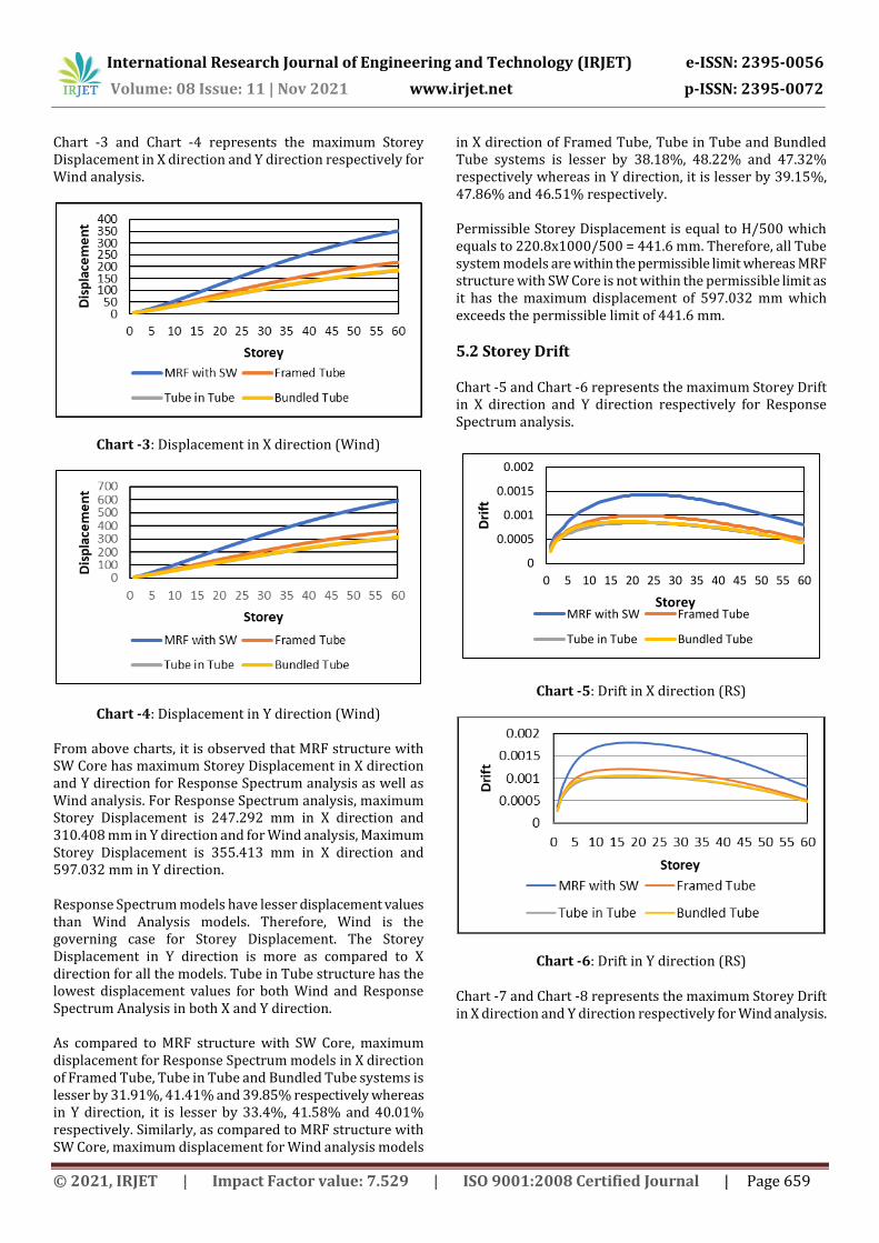
Chart -3 and Chart -4 represents the maximum Storey Displacement in X direction and Y direction respectively for Wind analysis.
Chart -3: Displacement in X direction (Wind)
Chart -4: Displacement in Y direction (Wind)
From above charts, it is observed that MRF structure with SW Core has maximum Storey Displacement in X direction and Y direction for Response Spectrum analysis as well as Wind analysis. For Response Spectrum analysis, maximum Storey Displacement is 247.292 mm in X direction and 310.408 mm in Y direction and for Wind analysis, Maximum Storey Displacement is 355.413 mm in X direction and 597.032 mm in Y direction. Response Spectrum models have lesser displacement values than Wind Analysis models. Therefore, Wind is the governing case for Storey Displacement. The Storey Displacement in Y direction is more as compared to X direction for all the models. Tube in Tube structure has the lowest displacement values for both Wind and Response Spectrum Analysis in both X and Y direction. As compared to MRF structure with SW Core, maximum displacement for Response Spectrum models in X direction of Framed Tube, Tube in Tube and Bundled Tube systems is lesser by 31.91%, 41.41% and 39.85% respectively whereas in Y direction, it is lesser by 33.4%, 41.58% and 40.01% respectively. Similarly, as compared to MRF structure with SW Core, maximum displacement for Wind analysis models
in X direction of Framed Tube, Tube in Tube and Bundled Tube systems is lesser by 38.18%, 48.22% and 47.32% respectively whereas in Y direction, it is lesser by 39.15%, 47.86% and 46.51% respectively. Permissible Storey Displacement is equal to H/500 which equals to 220.8x1000/500 = 441.6 mm. Therefore, all Tube system models are within the permissible limit whereas MRF structure with SW Core is not within the permissible limit as it has the maximum displacement of 597.032 mm which exceeds the permissible limit of 441.6 mm.
5.2 Storey Drift
Chart -5 and Chart -6 represents the maximum Storey Drift in X direction and Y direction respectively for Response Spectrum analysis.
0
0.0005
0.001
0.0015
0.002
0 5 10 15 20 25 30 35 40 45 50 55 60
Drift
StoreyMRF with SW Framed Tube
Tube in Tube Bundled Tube
Chart -5: Drift in X direction (RS)
Chart -6: Drift in Y direction (RS)
Chart -7 and Chart -8 represents the maximum Storey Drift in X direction and Y direction respectively for Wind analysis.
International Research Journal of Engineering and Technology (IRJET) e-ISSN: 2395-0056
Volume: 08 Issue: 11 | Nov 2021 www.irjet.net p-ISSN: 2395-0072
From above charts, it is observed that MRF structure with SW Core shows maximum Storey Drift in X direction and Y direction for Response Spectrum analysis as well as Wind analysis. For Response Spectrum analysis, maximum Storey Drift is 0.001431 m in X direction and 0.001803 m in Y direction and for Wind analysis, Maximum Storey Drift is 0.001987 m in X direction and 0.003290 m in Y direction. Response Spectrum models have lesser drift values than Wind Analysis models. Therefore, Wind is the governing case for Storey Drift. The Storey Drift in Y direction is more as compared to X direction for all the models. Tube in Tube structure has the lowest drift values for both Wind and Response Spectrum Analysis in both X and Y direction. As compared to MRF structure with SW Core, maximum drift for Response Spectrum models in X direction of Framed Tube, Tube in Tube and Bundled Tube systems is lesser by 31.03%, 41.23% and 39.76% respectively whereas in Y direction, it is lesser by 32.83%, 42.04% and 40.82% respectively. Similarly, as compared to MRF structure with SW Core, maximum drift for Wind analysis models in X direction of Framed Tube, Tube in Tube and Bundled Tube systems is lesser by 37.29%, 48.21% and 47.46% respectively whereas in Y direction, it is lesser by 37.72%, 47.72% and 46.63% respectively.
For Wind Analysis, permissible Storey Drift is equal to hi/400 which equals to 3.6 x 1000 / 400 = 9 mm as per clause 5.4.1, page no. 5 of IS 16700 2017. Therefore, all models are in permissible limits. For Response Spectrum Analysis, permissible Storey Drift is equal to hi/250 which equals to 3.6 x 1000 / 250 = 14.4 mm as per clause 5.4.1, page no. 5 of IS 16700 (2017) and IS 1893: Part 1 (2016). Therefore, all models are within permissible limits.
5.3 Storey Shear
Chart -9 and Chart -10 represents the Storey Shear in X direction and Y direction respectively for Response Spectrum analysis.
Chart -9: Storey Shear in X direction (RS)
Chart -10: Storey Shear in Y direction (RS)
Chart -11 and Chart -12 represents the Storey Shear in X direction and Y direction respectively for Wind analysis.
International Research Journal of Engineering and Technology (IRJET) e-ISSN: 2395-0056
Volume: 08 Issue: 11 | Nov 2021 www.irjet.net p-ISSN: 2395-0072
For Response Spectrum models, Tube in Tube structure has highest Storey Shear in X direction at 20036.86 KN and in Y direction at 18288.39 KN whereas MRF structure with SW Core has the lowest Storey Shear in X direction at 16796.39 KN and in Y direction at 15325.94.39 KN. Base Shear values for Wind Analysis models are comparatively higher as compared to Response Spectrum models.
5.4 Time Period
Chart -13 represents the Time Period for Response Spectrum analysis.
Chart -13: Time Period (RS)
Chart -14 represents the Time Period for Wind analysis.
Chart -14: Time Period (Wind)
MRF structure with Shear Wall Core has the highest Time Period for both Response Spectrum models (8.027s) and Wind analysis models (6.39s) whereas Tube in Tube structure has the lowest Time Period for both Response Spectrum models (6.224 s) and Wind analysis models (5.045 s). As compared to MRF structure with SW Core, Time Period for Response Spectrum models of Framed Tube, Tube in Tube and Bundled Tube systems is lesser by 17.78%, 22.46% and 21.61% respectively. Similarly, as compared to MRF structure with SW Core, Time Period for Wind analysis models of Framed Tube, Tube in Tube and Bundled Tube systems is lesser by 17.18%, 21.05% and 20.45% respectively.
6. CONCLUSIONS From the above results and observations, the effects of Tall Tubular structures are summarized on the responses such as Storey Displacement, Storey Drift, Storey Shear and Time Period in the present study and on the basis of the results, the following conclusions are drawn. • Two sets of analysis were performed wherein set 1
includes Response Spectrum models with factored modifiers and set 2 includes Wind Analysis models with unfactored modifiers.
• All Tube system models from both sets are within the permissible limit for Maximum Displacement whereas MRF structure with SW Core is not within the permissible limit.
• All models from both sets are within the permissible limit for Maximum Storey Drift.
• Storey Displacement as well as Storey Drift is minimum for Tube in Tube System while maximum for MRF structure with SW Core.
• The most effective structural systems to limit and reduce the Storey Displacement as well as Storey Drift are Tube in Tube system and Bundled Tube System.
International Research Journal of Engineering and Technology (IRJET) e-ISSN: 2395-0056
Volume: 08 Issue: 11 | Nov 2021 www.irjet.net p-ISSN: 2395-0072
• Base Shear values for Wind Analysis models are comparatively higher as compared to Response Spectrum models.
• MRF structure with Shear Wall Core has the highest Time Period for both Response Spectrum models and Wind analysis models.
• Tube in Tube structure has the lowest Time Period for both Response Spectrum models and Wind analysis models.
• The Tubular systems are strong enough to resist wind and earthquake loads.
• Based on the results obtained, Winds loads are dominant.
• On the basis of structural performance and stability, Tube in Tube and Bundled Tube structure provide better performance for resisting lateral loads.
REFERENCES [1] Nakul Khanna and Jagdish Chand, “Optimum Structural
Design for High Rise Building”, International Journal of Innovative Technology and Exploring Engineering (IJITEE), ISSN: 2278-3075, Vol. 8, Issue 8, 8 June 2019.
[2] S. Vijaya Bhaskar Reddy and M. Eadukondalu (2018), “Study of Lateral Structural Systems in Tall Buildings”, International Journal of Applied Engineering Research, ISSN: 0973-4562, Vol. 13, Number 15, 2018, pp. 11738-11754.
[3] Mohan K, Rahul and Virendra Kumara K, “Analysis of Different Forms of Tube in Tube Structures Subjected to Lateral Loads”, International Journal of Innovative Research in Technology (IJIRT), ISSN: 2349-6002, Vol.4, Issue 2, July 2017.
[4] Hojat Allah Ghasemi, “Optimal Design of High-Rise Building Bundled Tube Systems”, Advances in Science and Technology Research Journal, Vol. 10, No. 30, 1 June 2016, pp. 96-102, doi: 10.12913/22998624/62732.
[5] Mir M. Ali and Kyoung Sun Moon, “Structural Developments in Tall Buildings: Current Trends and Future Prospects”, Architectural Science Review, Vol. 50, No. 3, 13 June 2007, pp. 205-223.
[6] Feng Fu, “Design and analysis of tall and complex structures”, Butterworth-Heinemann, 2018.
[7] Mario Salvadori, “Why Buildings Stand Up: The Strength of Architecture”, Norton, 2002.
[8] C. V. R. Murty, Rupen Goswami, A. R. Vijayanarayanan, and Vipul V. Mehta, “Some Concepts in Earthquake Behaviour of Buildings”, GSDMA, 2012.
[9] IS 1893: Part 1 (2016), “Criteria for Earthquake Resistant Design of Structures”, Sixth Revision, BIS, New Delhi, India.
[10] IS 875: Part 1 (1987) Reaffirmed 2018, “Code of practice for design loads (Other Than Earthquake) for buildings and structures: Part 1 dead loads - Unit weights of building materials and stored materials”, Second Revision, BIS, New Delhi, India.
[11] IS 875: Part 2 (1987) Reaffirmed 2018, “Code of practice for design loads (Other Than Earthquake) for buildings and structures: Part 2 imposed loads”, Second Revision, BIS, New Delhi, India.
[12] IS 875: Part 3 (2015) Reaffirmed 2020 “Design Loads (Other than Earthquake) for Buildings and Structures -
Code of Practice Part 3 Wind Loads”, Third Revision, BIS, New Delhi, India.
[13] IS 16700 (2017) “Criteria for Structural Safety of Tall Concrete Buildings”, BIS, New Delhi, India.
[14] IS 456 (2000) Reaffirmed 2011, “Plain and Reinforced Concrete - Code of Practice”, Fourth Revision, BIS, New Delhi, India.
[15] IS 13920 (2016) “Ductile Design and Detailing of Reinforced Concrete Structures Subjected to Seismic Forces - Code of Practice”, First Revision, BIS, New Delhi, India.