Dynamic Loads and Applications 2 0. Introduction: Dynamic Loads and Applications Introduction Introduction Common engineering design usually focuses around static loads. With this in mind, is important to realise that static loads are indeed a very special case that - theoretically speaking - almost never occurs in real life. Clearly, the applicable safety factors for static design account for most usual effects of minor dynamic loading situations that are commonly addressed by using a static simplification. This brochure is intended to point out those cases, however, where such static simplification may cause severe misjudgement and usually under-design of important structures. The following sections seek to raise the awareness towards dynamic design problems, show how to classify, model and calculate them, and finally suggest an appropriate Hilti solution. Typical Dynamic Actions As will be described in detail in the following section, dynamic actions can generally be classified into 3 different groups: • Fatigue loads • Seismic loads • Shock loads Although the exact technical definitions will be given in the following section, a simple indicative explanation of each is helpful at this stage. • Fatigue loads are such that recur frequently during the life of a structure and are generally expected loads. • Seismic loads are induced by deformations of a structure due to seismic activity that may or may not be considered an ultimate state for the structure. • Shock loads are typically unique actions that can in some cases recur during the life of the structure. The following sections describe typical applications where dynamic actions occur, and where static simplification would generally lead to significant under-design.
Transcript
Dynamic Loads and Applications
2
0. Introduction: Dynamic Loads and Applications
Introduction
Introduction Common engineering design usually focuses around static
loads. With this in mind, is important to realise that static loads are indeed a very special case that - theoretically speaking - almost never occurs in real life. Clearly, the applicable safety factors for static design account for most usual effects of minor dynamic loading situations that are commonly addressed by using a static simplification. This brochure is intended to point out those cases, however, where such static simplification may cause severe misjudgement and usually under-design of important structures. The following sections seek to raise the awareness towards dynamic design problems, show how to classify, model and calculate them, and finally suggest an appropriate Hilti solution.
Typical Dynamic Actions As will be described in detail in the following section, dynamic actions can generally be classified into 3 different groups:
• Fatigue loads
• Seismic loads
• Shock loads
Although the exact technical definitions will be given in the following section, a simple indicative explanation of each is helpful at this stage.
• Fatigue loads are such that recur frequently during the life of a structure and are generally expected loads.
• Seismic loads are induced by deformations of a structure due to seismic activity that may or may not be considered an ultimate state for the structure.
• Shock loads are typically unique actions that can in some cases recur during the life of the structure.
The following sections describe typical applications where dynamic actions occur, and where static simplification would generally lead to significant under-design.
Dynamic Loads & Applications
3
Examples for Fatigue Loads Two main groups of fatigue type loading can be identified:
• Vibration type loading of fasteners with very high recurrence and usually low amplitude.
• Repeated loading and unloading of structures with high loads and frequent recurrence.
Vibration type loading is generally encountered in structures, such as
• Ventilators (most relevant standards and regulations assume a standard eccentricity to design for!)
• Various production machinery (rotating and linear)
• Breakers for rock, gravel an alike (rotating and linear)
• Structures subject to unsteady hydraulic effects (power plant equipment, pipe fasteners with frequent water hammer action, structures subject to water vortex loads, etc.)
• Fastenings subject to indirect loading through vibrating equipment in nearby location.
Usually, these cases are properly identified as "dynamic" and correspondingly designed for. Situations of "repeated loading and unloading" (e.g. vibrations) are much less spectacular and much less obvious as to their dynamic relevance. Thus, it is an explicit objective of this brochure to raise the awareness of the designing engineer especially with respect to such applications. Due to the substantial loads they usually include, fasteners are very frequently stressed close to their limits which in turn may well cause failure. Typical examples are:
• Hoisting equipment (autohoists, fastenings of jacks, etc.)
• Robots and other turning load carrying equipment
• Bridge components
• Loading structures (shutes for bulk material, conveying systems, etc.)
Examples for Seismic Loads Generally, all fastenings in structures situated in seismically active areas can be subject to seismic loading. However, due to cost considerations, usually only critical fastenings whose failure would result in loss of human life or significant
Dynamic Loads and Applications
4
weakening of the overall structure are designed for seismic loads. Furthermore, structures with importance for the time after an earthquake are generally equipped with such fastenings. Usual examples are:
• All fastenings of the primary structural members in buildings within active earthquake zones
• Fastenings of machinery and equipment mounted overhead and on walls (air conditioning aggregates, ventilators, heavy ducts and pipes, etc.)
• All fastenings in hospitals, schools and other structures that are generally used as shelters after catastrophic events
• Fastenings of critical equipment and corresponding sub-structure (major gas lines, equipment in the chemical and petrochemical industry, nuclear equipment, etc.)
Examples of Shock Loading Shock loads are mostly unusual loading situations, even though sometimes they are the only loading case a structure is designed for (e.g. crash barriers, protection nets, etc.) Most generally, shock loads occur as the result of
• Explosions (e.g. in industrial plants, power stations, war action, etc.)
• Falling parts and structures (e.g. as a result of seismic action, failure of structures, expected failure of wearable parts as is the case with rubber noise insulators for machinery, etc.)
• Hydraulic loads (e.g. water hammers, extraordinary operating conditions in hydro structures)
It should be emphasised, that shock loads are far more frequent than usually assumed. Furthermore, the load increases can be dramatic and easily in the order of 100 times the static load (see later examples). For example, a part posed directly onto an undeflected beam and then released instantly will cause the acting forces to double compared to the usually assumed static loading with infinitely slow loading (which is seldom the case).
Impact on Fasteners
5
1. Impact on Fasteners
Actions (loads)
Review of actions Often, it is not possible to accurately determine the actions (loads) towhich anchor / fasteners are subjected. In this case, it is possible tomake it with estimates for which standards specify the minimum levels tobe used for most modes of loading. The uncertainty in determining aaction (load) is compensated by selecting suitably adapted safety factors.
Static actions
Own (dead) weight
Permanent actions
Changing actions
Dynamic actions
harmonic
periodic
transient
impulse
Machines
Human
Wind
Waves
Seismic
Traffic
Constructionwork
Impact / crash
Explosion
Failure of building compo-nent
Impact on Fasteners
6
Static loads Static loads can be segregated as follows:• Own (dead) weight• Permanent actions
Loads of non-loadbearing components, e.g. floor covering, screed, orfrom constraint (due to temperature change or sinking of supports /columns)
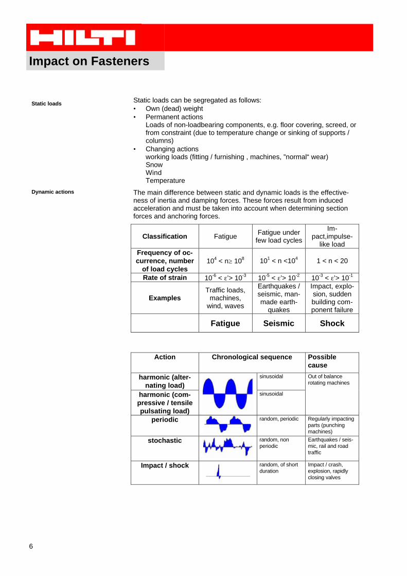
Dynamic actions The main difference between static and dynamic loads is the effective-ness of inertia and damping forces. These forces result from inducedacceleration and must be taken into account when determining sectionforces and anchoring forces.
Actions relevant to fatigue Actions causing fatigue have a large number of load cycles which pro-duce changes in stress in the affected fastening. These stresses result ina decrease in strength which is all the greater the larger the change instress and the larger the number of load cycles are (fatigue). Whenevaluating actions causing fatigue, not only the type of action, but alsothe planned or anticipated fastening life expectancy is of major impor-tance.
Direct / indirect action A direct action on a fastening exists when the fastening is immediatelystressed by forces, e.g. due to a machine in operation. A machine inoperation sets up vibration in its vicinity, also through its supports, whichthen indirectly incites building component vibration. This can lead tofatigue stressing of fastenings.
Determination of actions causing fatigue In most cases, the magnitude of action causing fatigue cannot be deter-mined accurately. The chronological sequence of the action and the in-fluence on each other of building component, fastened part and fastenerare crucial factors that have to be stipulated by the design engineer.When determining the fatigue-relevant magnitude of an action to which afastener is subjected, it is important, however, to remember that also theactions not occurring at the same time summate.
From a design / static point of view, the actions occurring at differenttimes are regarded separately. In the case of fatigue-relevant loading, allapplicable loads must be determined over the anticipated fastening lifeexpectancy. The following chart is intended to illustrate this:
Static design Dynamic design
time axis
t1 t2 t3
V1 V2
The design force is either V1 or V2.
∆V= V1 +V2
The dynamic designforce is ∆V.
N
V1 V2
The design force is either N, V1 or V2.
∆F
The dynamic designforce is
( )221
2 VVNF ++=∆
V
Impact on Fasteners
8
Earthquakes /seismic actions
Ground movement during an earthquake / seismic tremors leads to rela-tive displacement of a building foundation. Owing to the inertia of itsmass, the building cannot or is unable to follow this movement withoutdeformation. Due to the stiffness of the structure, restoring forces are setup and vibration is induced. This results in stress and strain for thestructure, the parts fastened and the installations. Earthquake frequen-cies often lead to resonance phenomena which cause larger vibrationamplitudes on the upper floors. The fastened components, the installa-tions and the fasteners or anchors required for them are then heavilystressed.
In view of the low ductility of anchors / fasteners, seismic loads generallyhave to be taken up by a high loading capacity and very little deforma-tion. A fastening should be able to withstand design basis earthquakeswithout damage. Determining the forces acting on a fastening is difficultand specialists thus provide them.
Shock Shock-like phenomena, i.e. a crashing vehicle, ship or aeroplane andfalling rocks, avalanches and explosions, have such characteristics as avery short duration and tremendously high forces which, however, gen-erally only occur as individual peaks. As the probability is slight that sucha phenomenon will occur during the life expectancy of the building com-ponents concerned, plastic deformation is usually permitted if such anevent takes place in order to avoid an uneconomical design. This meansthat the behaviour of the fastening must be as ductile as possible andthat it will be replaced after the phenomenon has occurred.
Under a loading of very brief duration, fastenings also display better be-haviour in the elastic range which permits higher permissible shockloads. These are determined during suitable tests, e.g. according toACLS9818.
The engineer responsible for a specific project must work out the mag-nitude of the action and the permissible deformation (elastic, elastic-plastic) each time.
Extraordinary actions Extraordinary actions include, among others, fire and corrosion. Theimplications for fastenings are described in other brochures.
Impact on Fasteners
9
Behaviour of materials
Material behaviour under static load-ing
The behaviour of material under static loading is described essentially bythe strength (tensile and compressive) and the elastic-plastic behaviourof the material, e.g. modulus of elasticity, shear (lateral) strain underload, etc. These properties are generally determined by carrying out sim-ple tests with specimens.
Fatigue behaviour If a material is subjected to a sustained load that changes with respect totime, it can fail after a certain number of load cycles even though theupper limit of the load withstood up to this time is clearly lower than theultimate tensile strength under static loading. This loss of strength isreferred to as material fatigue.
It is widespread practice to depict the fatigue behaviour of a material inthe form of so-called S-N curves (also called Wöhler curves). They showthe maximum load amplitude that can be withstood at a given number ofload cycles (for action with a sinusoidal pattern). If a level of stress canbe determined at which failure no longer occurs after any number of loadcycles, reference is made to fatigue strength or short-term fatiguestrength. Higher loads that can often only be withstood for a limited time,come within the low-cycle fatigue range or range of fatigue strength forfinite life.
Impact on Fasteners
10
Fatigue behaviour of steel The fatigue behaviour of various grades of steel is determined duringfatigue (Wöhler) tests. If a series of fatigue tests is carried out using dif-ferent mean stresses, many fatigue curves are obtained from which adecrease in the fatigue-resisting stress amplitude, σA , can be identified.The graphical depiction of the relationship between the mean stress, σm ,and the fatigue-resisting stress amplitude, σA , in each case is called thestress-number (S-N) diagram. Smith’s representation is mostly used to-day.
The grade of steel has a considerable influence on the alternatingstrength. In the case of structural and heat-treatable steels, it is approx.40% of the static strength, but this, of course, is considerably reduced ifthere are any stress raisers (notch effects). The fatigue strength of actualbuilding components is influenced by many factors:
• Stress raiser (notch effect)• Type of loading (tensile, shear, bending)• Dimensions• Mean stress
Stainless steels as well as plastics do not have a pronounced fatiguedurability (endurance) so that fatigue failure can even occur after loadcycles of >107.
Fatigue behaviour of concrete The failure phenomenon of concrete under fatigue loading is the sameas under static loading. In the non-loaded state, concrete already hasmicro-cracks in the zone of contact of the aggregates and the cementpaste which are attributable to the aggregates hindering shrinkage of thecement paste. The fatigue strength of concrete is directly dependent onthe grade of concrete. A concrete with a higher compressive strengthalso has a higher fatigue strength. Concrete strength is reduced to about60 – 65% of the initial strength after 2'000'000 load cycles.
Anchor Behaviour
11
2. Anchor Behaviour
Behaviour when subjected todynamic action
In view of the fact that dynamic action can have very many differentforms, only the basic information has been given in the following that isrequired to understand fastening behaviour.
Fatigue
Fatigue behaviour of single anchor inconcrete
The fatigue behaviour of steel and concrete is described in chapter 1.When a large number of load cycles is involved, i.e. n>104, it is alwaysthe anchor in single fastenings that is crucial (due to steel failure). Theconcrete can only fail when an anchor is at a reduced anchorage depthand subjected to tensile loading or an anchor is at a reduced distancefrom an edge and exposed to shear loading.
In the range of short-term strength, i.e. n<104, the concrete can also becrucial. This is dependent very much on the cross-sectional area of thesteel in relation to the anchorage depth, i.e. a large diameter combinedwith a small anchorage depth => concrete failure or a small diameterwith a large anchorage depth => steel failure.
Multiple-anchor fastenings Individual anchors in a multiple-anchor fastening can have a differentelastic stiffness and a displacement (slip) behaviour that differs from oneanchor to another, e.g. if an anchor is set in a crack. This leads to a re-distribution of the forces in the anchors during the appearance of the loadcycles. Stiffer anchors are subjected to higher loads, whereas the loadsin the weaker anchors is reduced. Allowance is made for these two ef-fects by using a reduction factor for multiple-anchor fastenings. It is de-termined during defined tests.
Influence of anchor pretensioning The behaviour of anchors under dynamic loading is decisively improvedby anchor pretensioning (preload). If an external working load, FA, actson a pretensioned anchor fastening, the fatigue-relevant share of theload cycle taken by the bolt is only the considerably smaller share of theforce in the bolt, FSA.
FA: external working load FV: pretensioning forceFK: clamping force Sscrew: bolt stiffnessFSA: share relevant to fatigue S clamped parts stiffness of clamped parts
Anchor Behaviour
12
Consequently, the existence of a pretensioning force is of crucial signifi-cance for the fatigue behaviour of an anchor (fastener). In the course oftime, however, all anchors lose some of the pretensioning force. Thisloss is caused by creep of the concrete, primarily in the zone in which theload is transferred to the concrete, due to relative deformation in turns ofthe bolt thread and relaxation in the bolt shank.
Tests have shown that comparable losses of pretensioning force can bemeasured in anchors (fasteners) that have quite different anchoringmechanisms, such as cast-in headed studs, undercut anchors and ex-pansion anchors. As a result, a residual pretensioning force of 30 to 50%the initial force must be expected after a considerable time if no counter-measures are taken.
Pretensioning force of anchor in acrack
If an anchor is set in a crack, the pretensioning force decreases to zeroand cannot, consequently, be taken into account for a fastening beingdesigned to withstand fatigue.
Influence of pretensioning onanchors loaded in shear
The clamping force between the part fastened and the base material, asshown above, is directly dependent on the pretensioning force in theanchor. As a rule, the fatigue strength of steel under shear loading is notas high as under pure tensile loading. In view of this, an attempt shouldbe made to transfer at least a part of the dynamic shear force into theconcrete by friction. Accordingly, if the pretensioning force is high, theshare that the anchor must take up is smaller. This has a considerableinfluence on the number and size of anchors required.
It is recommended that shear pins be provided to take up the dynamicshear forces. As a result, the anchors, provided that the through-hole hasa suitable shape, can be designed for pure tensile loading.
Pretensioning force in stand-off fas-tenings
In stand-off fastenings, the section of the bolt above the concrete is notpretensioned. The type of threaded rod alone, i.e. rolled after heat treat-ment or tempered after heat treatment, thus determines the fatigue du-rability of the fastenings. The pretensioning force in anchors is, never-theless, important to achieve a high level of fastening stiffness.
Influence of type of thread How the thread is produced, has a decisive influence on the fatiguestrength. A thread rolled after bolt heat treatment has a higher ultimatestrength than a thread tempered after heat treatment. All threads of Hiltianchors are rolled after heat treatment. Similarly, the diameter of athread has a decisive influence on the ultimate strength. This decreaseswith increasing diameter.
Anchor Behaviour
13
Earthquakes (seismic loading)
Load peaks caused by earthquakes Anchors (fasteners) subjected to seismic loading can, under circum-stances, be stressed far beyond their static loading capacity.
In view of this, the respective suitability tests are carried out using a levelof action (loading) that is considerably higher than the working load level.The behaviour of anchors under seismic action depends on the magni-tude of loading, the direction of loading, the base material and the typeof anchor. After an earthquake, the loading capacity (ultimate state) of ananchor is considerably reduced (to 30 – 80% of the original resistance.)
Anchor design as a part of the overallconcept
When designing anchor fastenings, it is important to remember that theycannot be regarded as something isolated to take up seismic forces, butthat they must be incorporated in the overall context of a design. As an-chors are generally relatively short and thus also stiff items, the possibil-ity of taking up energy in an anchor (fastener) is restricted. Other buildingcomponents are usually more suitable for this purpose. It is also difficultto foresee what loads will actually be imposed.
Impact and shock-like loads
Load increase times in the range of milliseconds can be simulated duringtests on servo-hydraulic testing equipment. The following main effectscan then be observed:
• deformation is greater when the breaking load is reached.• the energy absorbed by an anchor is also much higher.• breaking loads are of roughly the same magnitude during static
loading and shock-loading tests.In this respect, more recent investigations show that the base material(cracked or non-cracked concrete), has no direct effect on the loadbear-ing behaviour.
Anchor Behaviour
14
Suitability of anchors for dynamic loading
Suitability under fatigue loading Both mechanical and chemical anchors are basically suitable for fasten-ings subjected to fatigue loading. As, first and foremost, the grade ofsteel is crucial, Hilti manufactures the HDA and HVZ anchors of specialgrades of steel resistant to fatigue and has also subjected them to suita-bly tests. Where other anchors are concerned, global statements aboutultimate strengths have to be relied on, e.g. those from mechanical engi-neering.
Suitability under seismic loading Where fastenings subjected to seismic loading are concerned, chemicalanchors take preference. There are, however, accompanying require-ments to be met, such as behaviour in a fire or at high temperatures, i.e.load-displacement behaviour, which restrict the use of this type of anchorand make mechanical systems preferable.
Suitability under shock loading To date, mechanical anchor systems have been used primarily for appli-cations in civil defence installations. These mechanical anchors havehad their suitability proofed when set in cracked concrete. Recently, ad-hesive systems suitable for use in cracked concrete have been devel-oped, e.g. the HVZ anchor, whose suitability for shock loading is alsoverified. For other shock-like loads, such as those acting on the fasten-ings of guide rail systems, both mechanical anchors, e.g. fastening ofNew Jersey profiles with the HUC anchor, and chemical systems, e.g.the HAS with the HVU for crash barrier systems, can be considered.
Anchor Design
15
3. Anchor Design
The resistance of anchors for the different dynamic impacts varies sig-nificantly. On the following pages the state of the art is briefly described.In addition to this the national and international regulations have to beconsidered.
Fatigue
External load The fatigue loads are described often as repeated changes between aminimum and a maximum load level. The smallest, continuously actingload is the static load F; the difference between the continuously actingload F and the maximum load is the fatigue-relevant part of the load ∆F.For shear loads the fatigue-relevant load ∆V acts directly on the fastenerif the friction between baseplate and base material is exceeded. For ten-sile loads the fatigue relevant part of the external load ∆N in the bolt hasto be determined.
For a simplified design according to the DIBt-approval all loads are as-sumed to be fatigue relevant (∆F=F+∆F), friction and the pretensionforce in the anchor are not considered (=0).
Prestressing force in the anchor The prestressing force in uncracked concrete, that can be taken intoaccount respecting all the long term effects, is:
dk
kMkF
u
ddB ⋅
⋅⋅= ∞1
,
withFB,d pretension force in the anchork1 factor determined in tests = 0.5Md tightening torque [Nm]k� long term factor
without poststressing0.3 for HDA and 0.2 for HVZwith regular poststressing:0.4 for HDA and 0.3 for HVZ
ku conversion factor = 0.3d nominal anchor diameter [mm]
In a crack the pretension force vanishes and is therefor equal to 0.
Anchor Design
16
Fatigue relevant part of the tensileforce in the anchor
Force in bolt:
at static Load Nd:
ss
NNsFNif
NNsFNif
ddudBd
ddudBd
+⋅=+⋅>
=+⋅≤
1:)1(
:)1(
,,
,,
at maximum load Nd+∆N0d:
( )( )0
,,0
0,,
0
:)1(
1:)1(
dddodBdd
dddodBdd
NNNsFNNif
ss
NNNsFNNif
∆+=+⋅>∆++
∆+=+⋅≤∆+
s = 0.67
fatigue-relevant tensile force in bolt: ∆Nd = No,d – Nu,d
If maximal shear force Vd+∆Vod < VRd , then the acting force on the an-
chor ∆Vd=0, otherwise the total external force is assumed to act on theanchor ∆Vd=∆Vo
d.
Static design The static design should be done according to normal anchor design inaccordance with national and international regulations and approvals(ETA, ICBO, etc).
Anchor Design
17
Fatigue design In general the fatigue design should be done for the fatigue-relevant partof the external force ∆F and the relevant number of load cycles n.
∆FR,d(n) > ∆Fd
For simplified design the number of load cycles is n≥2'000'000 and thetotal load is fatigue-relevant.
Identification of fatigue resistances For tensile and shear forces the resistances for steel and concrete fa-tigue should be determined. These values (∆NRd,s, ∆NRd,c, ∆VRd,s, ∆VRd,c)are identified with tests for each number of load cycles (Wöhler Curves).
−⋅∆−+∆
−⋅∆−+∆
=∆
−⋅∆−+∆
−⋅∆−+∆
=∆
dcRd
dcRdcRdcRd
dsRd
dsRdsRdsRd
Rd
dcRd
dcRdcRdcRd
dsRd
dsRdsRdsRd
Rd
NN
NNNN
NN
NNNN
N
NN
NNNN
NN
NNNN
N
,
0,,
0,
,
0,,
0,
,
0,,
0,
,
0,,
0,
)(
)(
min
)(
)(
min
For group fastenings a group factor has be taken into account, whichgives the reduction due to load redistribution from the more flexible tothe stiffer anchors.
Anchor Design
18
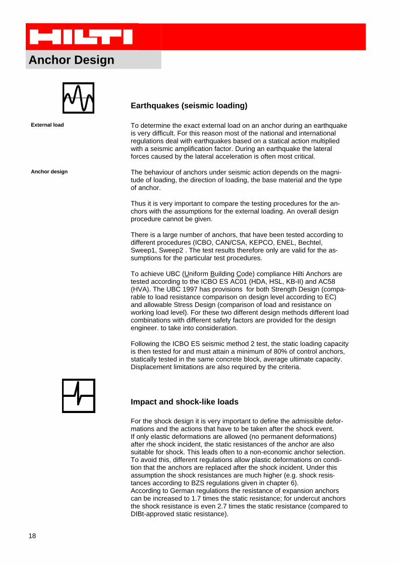
Earthquakes (seismic loading)
External load To determine the exact external load on an anchor during an earthquakeis very difficult. For this reason most of the national and internationalregulations deal with earthquakes based on a statical action multipliedwith a seismic amplification factor. During an earthquake the lateralforces caused by the lateral acceleration is often most critical.
Anchor design The behaviour of anchors under seismic action depends on the magni-tude of loading, the direction of loading, the base material and the typeof anchor.
Thus it is very important to compare the testing procedures for the an-chors with the assumptions for the external loading. An overall designprocedure cannot be given.
There is a large number of anchors, that have been tested according todifferent procedures (ICBO, CAN/CSA, KEPCO, ENEL, Bechtel,Sweep1, Sweep2 . The test results therefore only are valid for the as-sumptions for the particular test procedures.
To achieve UBC (Uniform Building Code) compliance Hilti Anchors aretested according to the ICBO ES AC01 (HDA, HSL, KB-II) and AC58(HVA). The UBC 1997 has provisions for both Strength Design (compa-rable to load resistance comparison on design level according to EC)and allowable Stress Design (comparison of load and resistance onworking load level). For these two different design methods different loadcombinations with different safety factors are provided for the designengineer. to take into consideration.
Following the ICBO ES seismic method 2 test, the static loading capacityis then tested for and must attain a minimum of 80% of control anchors,statically tested in the same concrete block, average ultimate capacity.Displacement limitations are also required by the criteria.
Impact and shock-like loads
For the shock design it is very important to define the admissible defor-mations and the actions that have to be taken after the shock event.If only elastic deformations are allowed (no permanent deformations)after rhe shock incident, the static resistances of the anchor are alsosuitable for shock. This leads often to a non-economic anchor selection.To avoid this, different regulations allow plastic deformations on condi-tion that the anchors are replaced after the shock incident. Under thisassumption the shock resistances are much higher (e.g. shock resis-tances according to BZS regulations given in chapter 6).According to German regulations the resistance of expansion anchorscan be increased to 1.7 times the static resistance; for undercut anchorsthe shock resistance is even 2.7 times the static resistance (compared toDIBt-approved static resistance).
PI Fatigue HDA
19
4. Productinformation Fatigue ResistancesThe following anchor resistances for tensile, shear and combined loads are the approvedvalues from the DIBt (Deutsches Institut für Bautechnik). This Productinformation is only validtogether with the general Productinformation given in the Fastening Technology ManualFTM.In addition to this the dynamic set (Appendix A) has to be used.
For the design the following assumptions have to be taken into consideration:• all applied loads are fatigue relevant• load safety factor γF=1.0• for group fixings a group factor has to be considered (redistribution of loads in the anchor
group)• number of load cycles n≥2'000'000• design with reduced anchor spacings, edge distances or other concrete qualities is done
according Hilti-cc-method (Hilti concrete capacity method: simplified method acc. to ETAGannex C)
• the concrete resistance has to be reduced
4.1 Productinformation HDA
Basic load data (for a single anchor): HDA-P (n≥≥2'000'000)
steel failure in cracked and uncracked concrete:Characteristic resistance ∆Rk [kN]: concrete C20/25 (according DIBt)
Group factors: Tension: γγF,N / Shear: γγF,V γγF,N=γγF.V=1.0 for single anchorγγF,N= 1.3 γγF.V=1.2 for more than one anchor
Basic load data (for a single anchor): HDA-T (n≥≥2'000'000)steel failure in cracked and uncracked concrete:Characteristic resistance ∆Rk [kN]: concrete C20/25 (according DIBt)
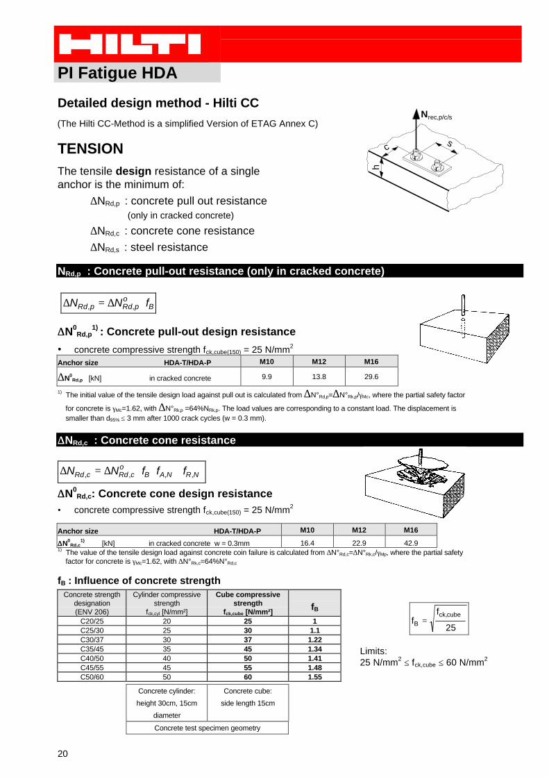
1) The initial value of the tensile design load against pull out is calculated from ∆N°Rd,p=∆N°Rk,p/γMc, where the partial safety factor
for concrete is γMc=1.62, with ∆N°Rk,p =64%NRk,p. The load values are corresponding to a constant load. The displacement is smaller than d95% ≤ 3 mm after 1000 crack cycles (w = 0.3 mm).
1) [kN] in cracked concrete w = 0.3mm 16.4 22.9 42.9
1) The value of the tensile design load against concrete coin failure is calculated from ∆N°Rd,c=∆N°Rk,c/γMp, where the partial safety factor for concrete is γMc=1.62, with ∆N°Rk,c=64%N°Rd,c
fB : Influence of concrete strengthConcrete strength
1) [kN] in cracked concrete w = 0.3 mm 3.1 4.6 9.5
∆∆V0Rd,c
1) [kN] in uncracked concrete 4.3 6.5 13.3
cmin [mm] cracked and non-cracked concrete 80 100 1501) The design value of the ultimate state in shear is calculated from the characteristic anchor shear resistance, ∆V°Rk,c, divided by ∆V°Rd,c= ∆V°Rk,c/γMc,V, where the partial safety factor, γMc,V, is 1.62 and ∆VRk,c=55%VRk,c
fB : Influence of concrete strengthConcrete strength
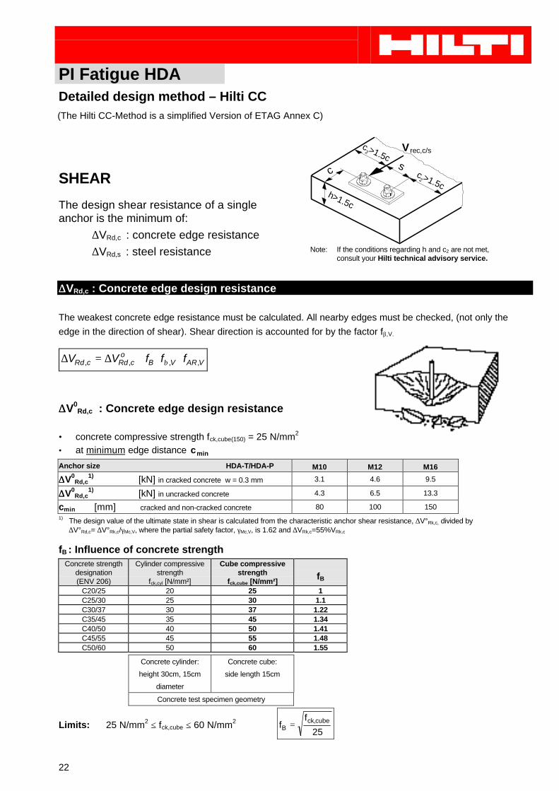
(The Hilti CC-Method is a simplified Version of ETAG Annex C)
PI Fatigue HDA
23
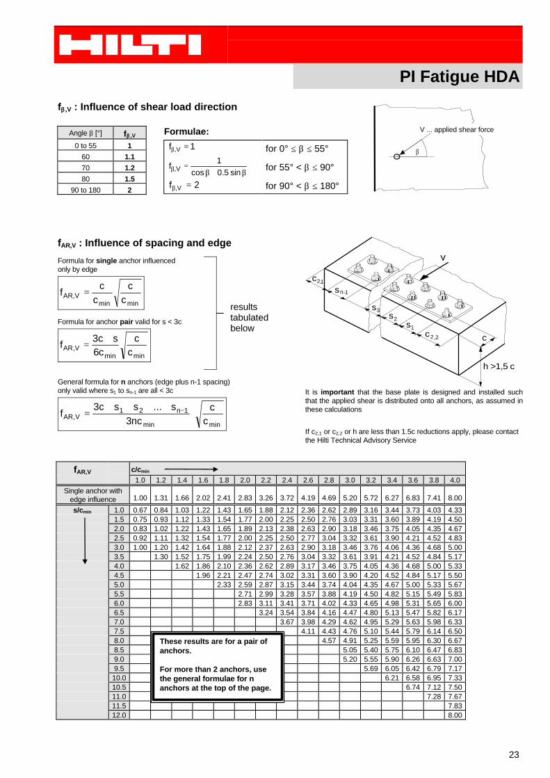
fββ ,V : Influence of shear load direction
Angle β [°] fββ ,V
0 to 55 1
60 1.1
70 1.2
80 1.5
90 to 180 2
Formulae:
1f V, =β
β+β=β sin5.0cos
1f V,
2f V, =β
for 0° ≤ β ≤ 55°
for 55° < β ≤ 90°
for 90° < β ≤ 180°
fAR,V : Influence of spacing and edge
Formula for single anchor influencedonly by edge
minminV,AR c
cc
cf =
Formula for anchor pair valid for s < 3c
minminV,AR c
cc6
sc3f
+=
General formula for n anchors (edge plus n-1 spacing)only valid where s1 to sn-1 are all < 3c
minmin
1n21V,AR c
cnc3
s...ssc3f ⋅
++++= −
ccs
ss
2,2
1
2
3
n-1sc2,1
h >1,5 c
It is important that the base plate is designed and installed suchthat the applied shear is distributed onto all anchors, as assumed inthese calculations
If c2,1 or c2,2 or h are less than 1.5c reductions apply, please contactthe Hilti Technical Advisory Service
∆N0Rd,p [kN] in cracked concrete 5.3 10.8 12.5 15.5 29.4
∆N0Rd,p [kN] in uncracked concrete 6.6 12.5 15.5 18.6 35.6
1) The initial value of the tensile design load against pull out is calculated from ∆N°Rd,p=∆N°Rk,p/γMp, where the partial safety factor
for concrete is γMp=2.27 (M10) resp. 1.94 (M12, M16, M20), with ∆N°Rk,p =60%NRk,p. The load values are corresponding to a constantload. The displacement is smaller than d95% ≤ 3 mm after 1000 crack cycles (w = 0.3 mm).
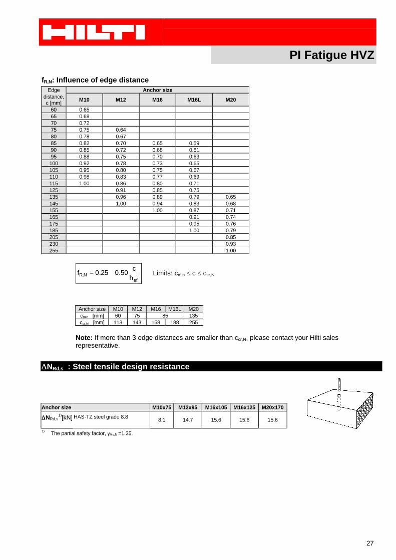
Note: If more than 3 edge distances are smaller than ccr,N, please contact your Hilti salesrepresentative.
PI Fatigue HVZ
28
SHEAR
The design shear resistance of a single anchor is the minimum of,
∆VRd,c : concrete edge resistance
∆VRd,s : steel resistance
Note: If the conditions shown for h and c2 cannot be observed, please contact your Hilti sales representative.
∆∆VRd,c : Concrete edge design resistance
The weakest concrete edge resistance must be calculated. All nearby edges must be checked, (not only theedge in the direction of shear). Shear direction is accounted by the factor fβ,V.
1) [kN] in non-cracked concrete 2.6 4.0 5.3 5.5 12.6
∆∆V0Rd,c
1) [kN] in cracked concrete 1.8 2.8 3.8 3.9 9.0
cmin [mm] Min. edge distance 60 75 85 1351) The design value of the ultimate state in shear is calculated from the characteristic anchor shear resistance, ∆V°Rk,c=60% V°Rk,c divided byγMc,V, where the partial safety factor, γMc,V, is 1.62.
fB,V : Influence of concrete strengthConcrete strength
1) The design shear resistance is calculated using ∆VRd,s= VRk,s/γMs,V.
∆∆VRd : System shear design resistance
∆∆VRd = minimum of ∆∆VRd,c and ∆∆VRd,s
COMBINED LOADS
steel: 0.1,
,
,
, ≤
∆∆⋅
+
∆∆⋅
αα
γ
γ
γ
γ
MsV
sRk
hSdVF
MsN
sRk
hSdNF
VV
NN
highest loaded single anchor
with α=0.76 (M10); α=0.87 (M12); α=1.0 (M16, M20)
These results are for a pair ofanchors.
For more than 2 anchors, usethe general formulae for nanchors at the top of the page.
PI Fatigue HVZ
30
concrete: 0.1,,
≤
∆
∆+
∆
∆
Mc
gcRk
gSd
Mc
gcRk
gSd
V
V
N
N
γγ
anchor group
PI Seismic
31
5. Productinformation Seismic
As described already in chapter 3 the anchor resistances depend a lot on the assump-tions of testing and the assumptions for the determination of the loads. There are a lot ofnational and international codes that have to be respected.ICBO Evaluation reports give the anchor resistances for the strength design and or forallowable stress method described in UBC 1997. For the following anchors EvaluationReports, which allow seismic design are available (download from Internetwww.ICBO.org):
HDA: ER-5608 issued April 1, 2000KB-II: ER-4627 issued July 1, 1998HSL: ER-3987 reissued July 1, 1998HVA: ER-5369 reissued March 1, 2000
For allowable stress design method it’s allowed to increase the statical resistances by%33 3
1 .
For design strength method the higher resistances are included in the load safety factors.
PI Shock
32
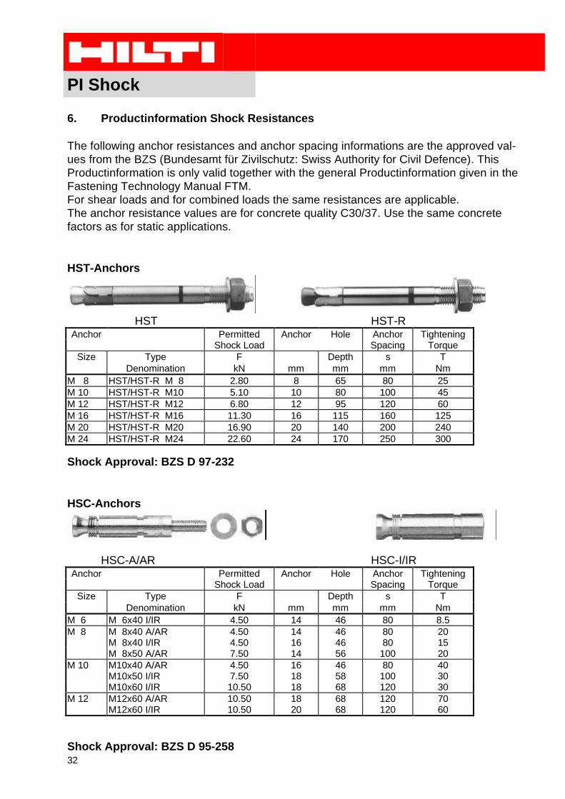
6. Productinformation Shock Resistances
The following anchor resistances and anchor spacing informations are the approved val-ues from the BZS (Bundesamt für Zivilschutz: Swiss Authority for Civil Defence). ThisProductinformation is only valid together with the general Productinformation given in theFastening Technology Manual FTM.For shear loads and for combined loads the same resistances are applicable.The anchor resistance values are for concrete quality C30/37. Use the same concretefactors as for static applications.
Assumptions:• all loads fatigue relevant• no prestressing force in anchor• stiff baseplate• γf,N= γf,V =1.0 (load safety factor for single anchor)• γf,N=1.3 (group factor for tensile load, preliminary data)• γf,V=1.2 (group factor for shear load, preliminary data)
7.1.2.1 Acting Loadssingle anchorstensile load on upper single anchor in upper row = highest loaded anchor(out of statical calculation):
kNkNN
NQ
h
Sd
Nf
h
Sd0.4
5.1
6.43.1
,=⋅==∆
γγ
tensile load on lower anchor row:
kNkNN
NQ
l
Sd
Nf
l
Sd4.0
5.1
5.03.1
,=⋅==∆
γγ
Total tensile load anchor group for concrete cone check (without γF,N)
kNkNkNNN
NNf
lSd
Nf
hSdg
Sd 8.63.1
4.02
3.1
0.4222
,,
=⋅+⋅=⋅+⋅=∆γγ
shear load on single anchor:
kNkN
n
VV
Q
Sd
VfSd5.4
5.14
5.222.1
,=
⋅⋅=
⋅=∆
γγ
with n: number of anchors in anchor group
Examples Fatigue
38
7.1.2.2 Resistance7.1.2.2.1 TensionSteel failure (check only with highest loaded anchor):
tensile steel resistance single anchorkNN sRd 8.11, =∆
Check single anchor:
34.08.11
0.4
,
==∆
∆
kN
kN
N
N
sRd
hSd ok
Concrete cone failure (check only with anchor group):statical group resistance:
NucrNecNs
Nc
Nc
cRk
g
cRk A
ANN
,,,0
,
,0
,,ψψψ ⋅⋅⋅⋅=
kNhfN efcubeccRk 7.59120303.83.8 5.15.1,
0, =⋅⋅=⋅⋅= (single undercut anchor)
( ) ( ) 222,
0, 625'140375 mmsA NcrNc ===
( )2
,
400'274
1205.12001205.1)1205.11301205.1(
mm
mmmmmmmmmmmmA Nc
=
⋅++⋅⋅⋅++⋅=
95.10,
, =Nc
Nc
A
A
ψs,N=1.0 (no edge)eccentricity due to bending moment:
mmkN
mmkNmmkNeN 52
1.5
655.0656.4=
⋅−⋅
=
78.0, =Necψ
0.1, =Nucrψ
kNN g
cRk8.90
,=
kNNN g
cRk
g
cRk1.58%64
,,=⋅=∆
(i.e. final resistance of concrete=64% statical resistance, acc. DIBt)
kNkNN
NMc
cRkcRd 8.35
62.1
1.58,, ==
∆=∆
γ (γMc acc. DIBt)
1/21
1
,, ≤
+=Ψ
NcrNNec se
4.6
0.5
eN
Examples Fatigue
39
check anchor group:
19.08.35
8.6
,
, ==∆
∆
kN
kN
N
N
cRd
cSd
Pullout failure (check only with highest loaded anchor):kNkNNfN
pRdBpRd2.158.131.10
,,=⋅=∆⋅=∆
with fB:factor for influence of concrete strength for C25/30
Check single anchor:
26.02.15
0.4
,
==∆∆
kN
kN
N
N
pRd
h
Sd ok
7.1.2.2.2 ShearSteel failure:
shear resistance single anchorkNV sRd 3.11, =∆ shear resistance of single anchor
check single anchor
40.03.11
5.4
,
==∆
∆
kN
kN
V
V
sRd
hSd ok
Concrete failure: not decisive (no edges)
7.1.2.2.3 Interaction
Steel failure single anchor:
74.04.11
5.4
8.11
0.4
,,
=+=∆
∆+
∆
∆kN
kN
kN
kN
V
V
N
N
sRd
hSd
sRd
hSd ok
Examples Fatigue
40
7.2 Simplified design for the fixing of unbalanced rotatingmachine in a concrete member
Given: Hilti undercut anchor HDAanchoring in cracked concrete,concrete strength class: C30/37proper weight of machine: m = 400 kg (max. load)unbalanced mass: m1 = 5.0kgradius of unbalance: r1 = 0.5mrotation speed: ω = 3'000 r/minthickness of concrete member: h > 250 mmspacing: s1= 800mm
s2= 1’600 mmlength of anchor plate: lx = 1’000 mmwidth of anchor plate: ly = 2’000 mmnumber of load cycle n = 2'000'000
Examples Fatigue
41
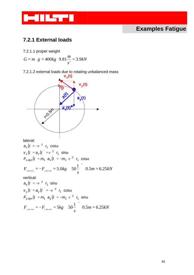
7.2.1 External loads
7.2.1.1 proper weight
kNs
mkggmG 9.381.9400
2=⋅=⋅=
7.2.1.2 external loads due to rotating unbalanced mass
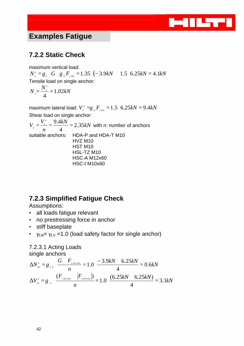
7.2.3 Simplified Fatigue CheckAssumptions:• all loads fatigue relevant• no prestressing force in anchor• stiff baseplate• γf,N= γf,V =1.0 (load safety factor for single anchor)
7.2.3.1 Acting Loadssingle anchors
kNkNkN
n
FGN dyny
Nf
h
Sd6.0
4
25.69.30.1max,,
,=
+−⋅=
+⋅=∆ γ
kNkNkN
n
FFV dynxdynx
vf
h
Sd1.3
4)25.625.6(
0.1)(
min,,max,,
,=
+⋅=
+⋅=∆ γ
Examples Fatigue
43
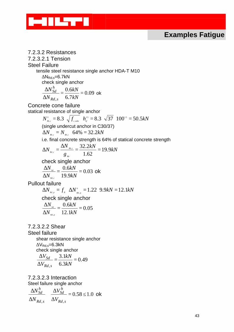
7.2.3.2 Resistances7.2.3.2.1 TensionSteel Failure
tensile steel resistance single anchor HDA-T M10∆NRd,s=6.7kNcheck single anchor
09.07.6
6.0
,
==∆∆
kN
kN
N
N
sRd
hSd ok
Concrete cone failurestatical resistance of single anchor
kNhfNefcubeccRk
5.50100373.83.8 5.15.1
,
0
,=⋅⋅=⋅⋅=
(single undercut anchor in C30/37)kNNN
cRkcRk2.32%64
,,=⋅=∆
i.e. final concrete strength is 64% of statical concrete strength
kNkNN
NMc
cRk
cRd9.19
62.1
2.32,
,==
∆=∆
γcheck single anchor
03.09.19
6.0
,
==∆∆
kN
kN
N
N
cRd
Sd ok
Pullout failurekNkNNfN
pRdBpRd1.129.922.10
,,=⋅=∆⋅=∆
check single anchor
05.01.12
6.0
,
==∆∆
kN
kN
N
N
pRd
Sd
7.2.3.2.2 ShearSteel failure
shear resistance single anchor∆VRd,s=6.3kNcheck single anchor
49.03.6
1.3
,
==∆∆
kN
kN
V
V
sRd
Sd
7.2.3.2.3 InteractionSteel failure single anchor
0.158.0,,
≤=∆
∆+
∆
∆
sRd
hSd
sRd
hSd
V
V
N
N ok
Examples Seismic
44
8. Examples Seismic Design
8.1 Rigidly floor mounted pump
Given: Baseplate with 4 Hilti anchorsanchoring in uncracked concrete,concrete strength class: C25/30 (≅4000psi)applied mass: m = 700 kgthickness of concrete member: h > 400 mmspacing: s1= 1000mm
s2= 700mmlength of anchor plate: lx = 1500 mmwidth of anchor plate: ly = 1000 mmclearance hole in baseplate: d=11mm (7/16”)
Examples Seismic
45
Horizontal force caused by Earthquake;GmFp ⋅=
where m is the systems mass and G is the seismic factor according to localregulations
( ppv FF ⋅= 31 if necessary according to local codes)
1. Tension1.1 Overturning in direction Fp acc. to sketch
°=⋅
⋅=
⋅⋅
=Φ −− 557002
10002tantan 1
22
111
snsn
( )
Nmm
mNN
s
mkg
snsnhF
nn
FgmT gp
pv
957.02
55sin1255cos
45.0400'34
150'181.9700
sincos
2
2211211
−=
⋅°
+⋅
°⋅+
+⋅−
=
⋅Φ
+⋅
Φ⋅+
+
+⋅−=
T1: tensile force on critical anchor 1n1: number of anchors along the lengthn2: number of anchors along the widths1: anchor spacing along the lengths2: anchor spacing along the width
φ: critical angle where maximum tension occurs 22
111tansnsn
⋅⋅
=Φ −
hg: height of center of gravity
1.2 Overturning short axis
Nm
mNN
s
mkg
ns
hF
nn
FgmT cppv 336
27.045.0400'3
4
150'181.97002
22212,1 −=
⋅⋅
++⋅−
=⋅
⋅+
+
+⋅−=
T1,2: tensile force on critical anchor 1 or 2
since the tensile load in both overturning considerations is negative, there is noadditional force in the anchor.
Examples Seismic
46
2. Shear
21 nn
FV p
+=
V: shear force on one bolt
NN
nn
FV p 850
4400'3
21
==+
=
Shear resistance according to ICBO ER 4627 for HKB 3/8” with 15/8” embedmentdepth in concrete wit a resistance of 4’000psi (133% of static resistance):
kNs
mlbskg
lbsVR 35.6%133*81.9453.0075'12
=⋅⋅=
Examples Shock
47
9. Examples Shock
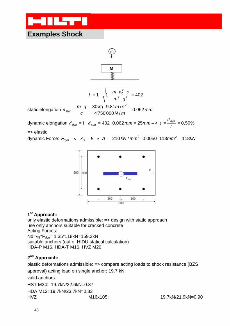
9.1 Inelastic Collision: Mass falling into a steel rope
Given: Baseplate with 6 Hilti anchorsanchoring in cracked concrete,concrete strength class: C40/50applied mass: m = 30 kgheight of fall = length of rope: L=5 metersdiameter of steel rope: 12 mmsteel elasticity: 210'000 N/mm2
thickness of concrete member: h > 400 mmspacing: s1=s2= 300mmlength of anchor plate: lx = 800 mmwidth of anchor plate: ly = 500 mm
simplified assumption: static elasticity of rope = dynamic elasticity of ropecross section of rope As=113 mm2
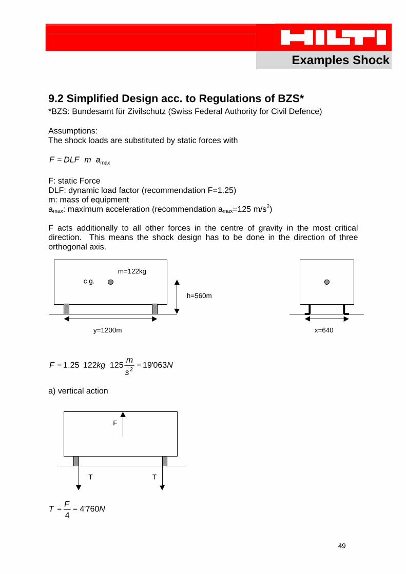
9.2 Simplified Design acc. to Regulations of BZS**BZS: Bundesamt für Zivilschutz (Swiss Federal Authority for Civil Defence)
Assumptions:The shock loads are substituted by static forces with
maxamDLFF ⋅⋅=
F: static ForceDLF: dynamic load factor (recommendation F=1.25)m: mass of equipmentamax: maximum acceleration (recommendation amax=125 m/s2)
F acts additionally to all other forces in the centre of gravity in the most criticaldirection. This means the shock design has to be done in the direction of threeorthogonal axis.
Daniel Schuler, Beat Erdin Einflüsse auf das Tragverhalten schockbeanspruchter Metallspreizdübelim gerissenen Beton, ACLS 9818, 1998
TW Schock 1995 Technische Weisung für die Schocksicherheit von Einbauteilen in Zivil-schutzbauten, Bundesamt für Zivilschutz, 1995
Test Reports Hilti AG
Test Reports Institut für Bauforschung, Universität Dortmund
DIBt-Zulassungen
ET Approvals
BZS Approvals
ICBO Approvals
Dynamic Set
52
Appendix A: Dynamic Set
General For all dynamic actions three main challenges can beidentified:1. For an easy installation the clearance hole always islarger than the external diameter of the anchor. For staticloads this is of negligible relevance, but for dynamic loadsany relative movement between baseplate and anchorcan have a negative impact.2. As most of the anchors are drilled manually they arenever 100% vertical. This leads also with pure tensileloads to bending moments in the anchor.3. With dynamic loads even properly installed anchorshave sometimes the problem, that the nuts start to loosenduring lifetime.
Dynamic Set To improve this situation Hilti has developed the so called“Dynamic Set”. This includes a special injection washer to fillup the clearance hole with HIT-HY150, a spherical washer toavoid the bending in the anchor, a standard nut and a spe-cial locknutto avoid any nut loosening.
Injection Washer spherical washer nut locknut
This dynamic set has to be used for all fatigue applicationsand the load values given in the “PI fatigue” in chapter 4 areonly valid in combination with this set. For all other applica-tions the use of this set is not mandatory but it helps to im-prove the situation especially if shear forces are acting.