60
Powerdrive FX & MD2 variable speed drives LSRPM - PLSRPM permanent magnet synchronous motors 18 kW to 500 kW Dyneo ® Motors & Drives
Powerdrive FX & MD2 variable speed drivesLSRPM - PLSRPM permanent magnet synchronous motors
18 kW to 500 kW
Dyneo® Motors & Drives
2 Dyneo® Motors & Drives - 5006 en - 2017.05 / g
Dyneo® Motors & DrivesPowerdrive FX & MD2 variable speed drives/LSRPM-PLSRPM permanent magnet synchronous motors
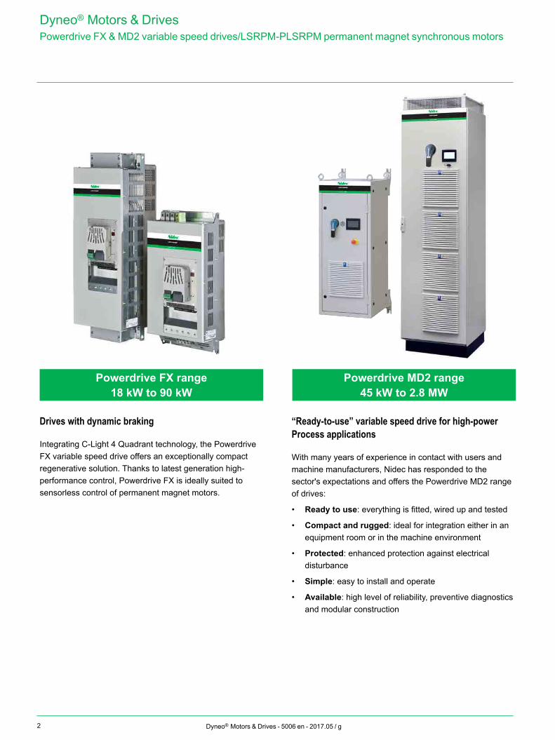
Drives with dynamic braking
Integrating C-Light 4 Quadrant technology, the Powerdrive FX variable speed drive offers an exceptionally compact regenerative solution. Thanks to latest generation high-performance control, Powerdrive FX is ideally suited to sensorless control of permanent magnet motors.
“Ready-to-use” variable speed drive for high-power Process applications
With many years of experience in contact with users and machine manufacturers, Nidec has responded to the sector's expectations and offers the Powerdrive MD2 range of drives:
• Ready to use: everything is fitted, wired up and tested
• Compact and rugged: ideal for integration either in an equipment room or in the machine environment
• Protected: enhanced protection against electrical disturbance
• Simple: easy to install and operate
• Available: high level of reliability, preventive diagnostics and modular construction
Powerdrive MD2 range45 kW to 2.8 MW
Powerdrive FX range18 kW to 90 kW
3Dyneo® Motors & Drives - 5006 en - 2017.05 / g
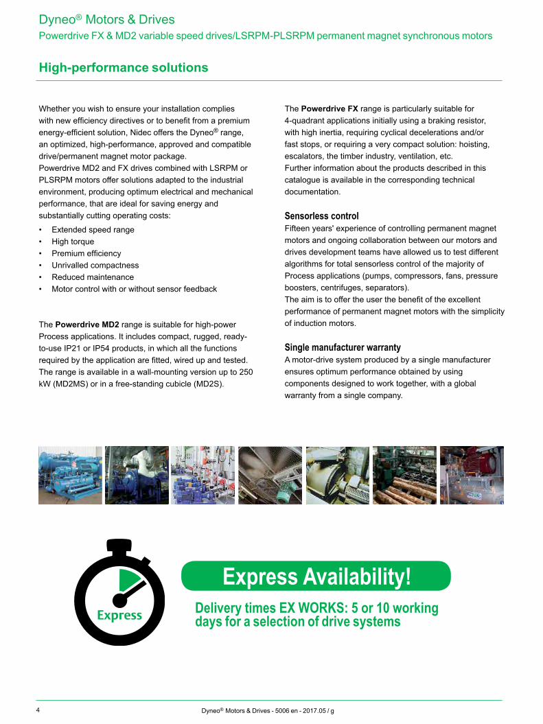
Energy savings
50 kWh65 kWh
80 kWh85 kWh
100 kWhInitial solution
Mechanical optimisation
IE3 motor
Drive and IE2 motor
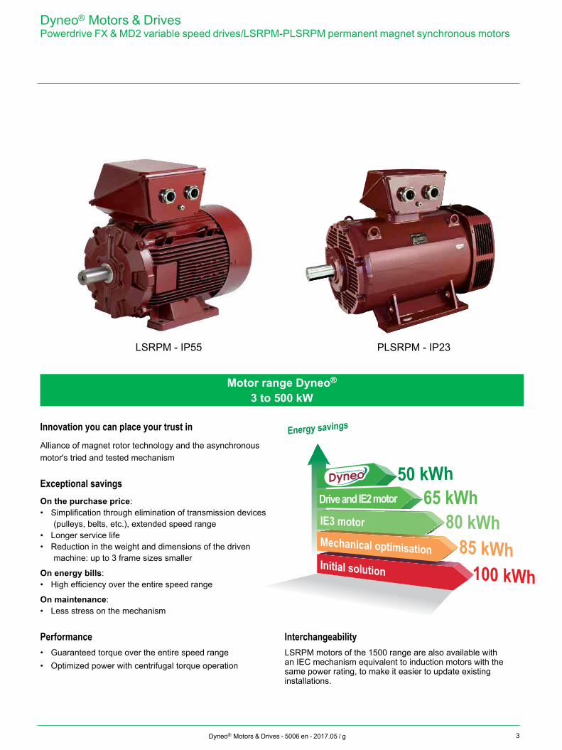
Innovation you can place your trust inAlliance of magnet rotor technology and the asynchronous motor's tried and tested mechanism
Exceptional savingsOn the purchase price:• Simplification through elimination of transmission devices
(pulleys, belts, etc.), extended speed range• Longer service life• Reduction in the weight and dimensions of the driven
machine: up to 3 frame sizes smaller
On energy bills:• High efficiency over the entire speed range
On maintenance:• Less stress on the mechanism
Performance• Guaranteed torque over the entire speed range• Optimized power with centrifugal torque operation
InterchangeabilityLSRPM motors of the 1500 range are also available with an IEC mechanism equivalent to induction motors with the same power rating, to make it easier to update existing installations.
Dyneo® Motors & DrivesPowerdrive FX & MD2 variable speed drives/LSRPM-PLSRPM permanent magnet synchronous motors
Motor range Dyneo®
3 to 500 kW
LSRPM - IP55 PLSRPM - IP23
4
Express
Dyneo® Motors & Drives - 5006 en - 2017.05 / g
Dyneo® Motors & DrivesPowerdrive FX & MD2 variable speed drives/LSRPM-PLSRPM permanent magnet synchronous motors
High-performance solutions
Whether you wish to ensure your installation complies with new efficiency directives or to benefit from a premium energy-efficient solution, Nidec offers the Dyneo® range, an optimized, high-performance, approved and compatible drive/permanent magnet motor package.Powerdrive MD2 and FX drives combined with LSRPM or PLSRPM motors offer solutions adapted to the industrial environment, producing optimum electrical and mechanical performance, that are ideal for saving energy and substantially cutting operating costs:
• Extended speed range• High torque• Premium efficiency• Unrivalled compactness• Reduced maintenance• Motor control with or without sensor feedback
The Powerdrive MD2 range is suitable for high-power Process applications. It includes compact, rugged, ready-to-use IP21 or IP54 products, in which all the functions required by the application are fitted, wired up and tested.The range is available in a wall-mounting version up to 250 kW (MD2MS) or in a free-standing cubicle (MD2S).
The Powerdrive FX range is particularly suitable for 4-quadrant applications initially using a braking resistor, with high inertia, requiring cyclical decelerations and/or fast stops, or requiring a very compact solution: hoisting, escalators, the timber industry, ventilation, etc.Further information about the products described in this catalogue is available in the corresponding technical documentation.
Sensorless controlFifteen years' experience of controlling permanent magnet motors and ongoing collaboration between our motors and drives development teams have allowed us to test different algorithms for total sensorless control of the majority of Process applications (pumps, compressors, fans, pressure boosters, centrifuges, separators).The aim is to offer the user the benefit of the excellent performance of permanent magnet motors with the simplicity of induction motors.
Single manufacturer warrantyA motor-drive system produced by a single manufacturer ensures optimum performance obtained by using components designed to work together, with a global warranty from a single company.
Express Availability!Delivery times EX WORKS: 5 or 10 working days for a selection of drive systems
5Dyneo® Motors & Drives - 5006 en - 2017.05 / g
Contents
INTRODUCTIONPowerdrive FX offer ..............................................................6
Powerdrive MD2 offer ...........................................................7
LSRPM - PLSRPM motors ..................................................8
Motors & Drives designation ................................................9
Selection method ...........................................................10-11
Efficiency ...........................................................................12
SELECTION1500 range ........................................................................13
1800 range ........................................................................14
2400 range ........................................................................15
3000 range ........................................................................16
3600 range ........................................................................17
4500 range ........................................................................18
5500 range ........................................................................19
PERFORMANCE1500 range - 0 to 1500 rpmTorque from 0 to 2300 N.m ............................................ 20-21
1800 range - 0 to 1800 rpmTorque from 0 to 2300 N.m ........................................... 22-23
2400 range - 0 to 2400 rpmTorque from 0 to 1400 N.m ........................................... 24-25
3000 range - 0 to 3000 rpmTorque from 0 to 1600 N.m ........................................... 26-27
3600 range - 0 to 3600 rpmTorque from 0 to 1500 N.m ........................................... 28-29
4500 range - 0 to 4500 rpm Torque from 0 to 360 N.m ...................................................30
5500 range - 0 to 5500 rpmTorque from 0 to 240 N.m ...................................................31
DRIVE DIMENSIONS
Powerdrive FX & MD2 ........................................................32
MOTOR DIMENSIONSShaft extensions .................................................................33
Foot mounted IM B3 ...........................................................34
Foot and flange mounted IM B35 .......................................35
Flange mounted IM B5 .......................................................36
Motors with options.............................................................37
INSTALLATION AND OPTIONSGeneral ...............................................................................38
Good wiring practice ...........................................................39
Typical variable speed drive installation .............................40
Selection of position sensor................................................41
Encoders ............................................................................42
Reinforced insulation ..........................................................43
Forced ventilation - Cable glands .......................................44
Thermal protection..............................................................45
MOTOR CONSTRUCTIONDefinition of “Index of Protection” (IP/IK) ............................46
External finish .....................................................................47
Mounting arrangements......................................................48
Bearings and lubrication .....................................................49
Terminal box and connection ........................................ 50-52
Motor vibration levels..........................................................53
Quality commitment ............................................................54
Standards and approvals.............................................. 55-56
Nameplates ........................................................................57
GENERAL INFORMATIONConfigurator ........................................................................58
Dyneo® Motors & DrivesPowerdrive FX & MD2 variable speed drives/LSRPM-PLSRPM permanent magnet synchronous motors
Nidec reserves the right to modify the design, technical specifications and dimensions of the products and solutions shown in this document. The descriptions cannot in any way be considered contractual.
6 Dyneo® Motors & Drives - 5006 en - 2017.05 / g
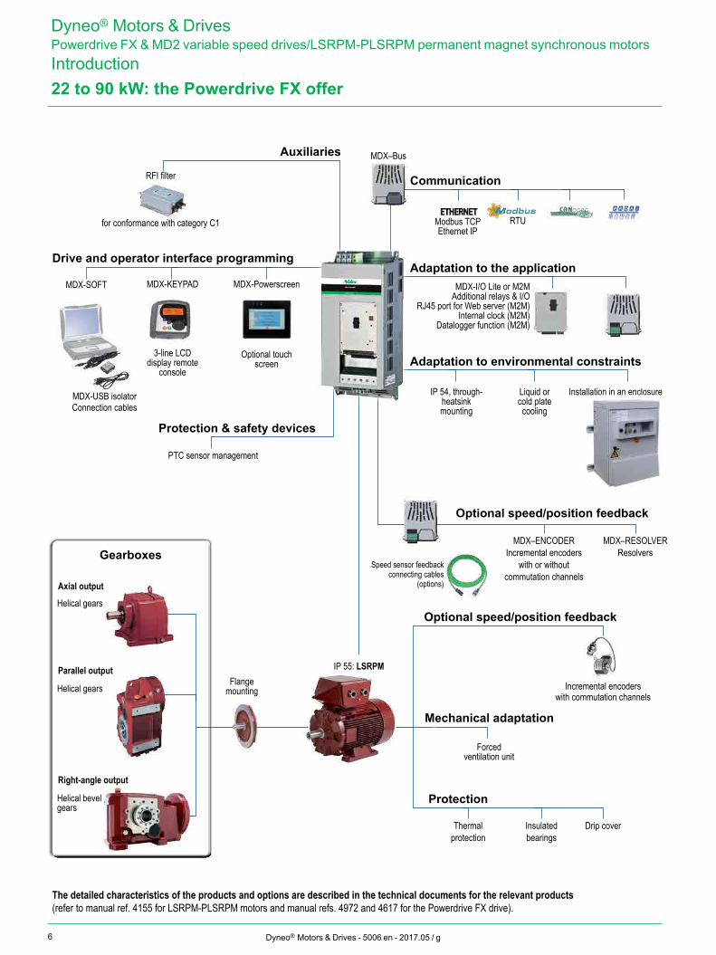
Dyneo® Motors & DrivesPowerdrive FX & MD2 variable speed drives/LSRPM-PLSRPM permanent magnet synchronous motorsIntroduction22 to 90 kW: the Powerdrive FX offer
IP 55: LSRPM
MDX-PowerscreenMDX-KEYPADAdaptation to the application
Communication
Optional speed/position feedback
Adaptation to environmental constraints
Auxiliaries
Protection & safety devices
Drive and operator interface programming
Gearboxes
Incremental encoders with commutation channels
Speed sensor feedback connecting cables
(options)Axial output
Parallel output
Right-angle output
Helical bevel gears
Helical gears
Helical gearsFlange
mounting
Forced ventilation unit
Thermal protection
Insulated bearings
Mechanical adaptation
Protection
Optional speed/position feedback
The detailed characteristics of the products and options are described in the technical documents for the relevant products(refer to manual ref. 4155 for LSRPM-PLSRPM motors and manual refs. 4972 and 4617 for the Powerdrive FX drive).
Drip cover
MDX–Bus
RFI filter
PTC sensor management
3-line LCD display remote
console
Optional touch screen
for conformance with category C1
Liquid or cold plate
cooling
IP 54, through-heatsink mounting
MDX-I/O Lite or M2MAdditional relays & I/O
RJ45 port for Web server (M2M)Internal clock (M2M)
Datalogger function (M2M)
MDX–ENCODERIncremental encoders
with or without commutation channels
MDX–RESOLVERResolvers
Modbus TCPEthernet IP
RTU
MDX-USB isolator
MDX-SOFT
Connection cablesInstallation in an enclosure
7Dyneo® Motors & Drives - 5006 en - 2017.05 / g
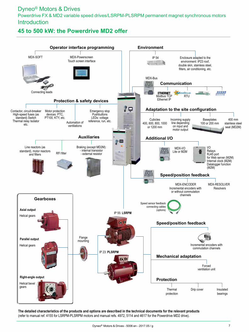
The detailed characteristics of the products and options are described in the technical documents for the relevant products(refer to manual ref. 4155 for LSRPM-PLSRPM motors and manual refs. 4972, 5114 and 4617 for the Powerdrive MD2 drive).
Dyneo® Motors & DrivesPowerdrive FX & MD2 variable speed drives/LSRPM-PLSRPM permanent magnet synchronous motorsIntroduction45 to 500 kW: the Powerdrive MD2 offer
IP 55: LSRPM
IP 23: PLSRPM
Gearboxes
Incremental encoders with commutation channels
Axial output
Parallel output
Right-angle output
Helical bevel gears
Helical gears
Helical gears
Flange mounting
Forced ventilation unit
Drip cover Insulated bearings
Thermal protection
Mechanical adaptation
Protection
Speed/position feedback
MDX-Powerscreen
Modbus TCPEthernet IP
RTU
MDX-RESOLVERMDX-ENCODER
Connecting leads
MDX-SOFT
MDX-Bus
IP 54
Communication
Environment
Speed/position feedback
Adaptation to the site configuration
Additional I/O
Operator interface programming
Auxiliaries
Protection & safety devices
Emergency stop Pushbuttons
LEDs: voltage reference, run, etc.
Braking (except MD2M):- internal transistor- external resistor
Enclosure adapted to the environment: IP23 roof,
double skin, stainless steel, filters, air conditioning, etc.
Incremental encoders with or without commutation
channels
Resolvers
Line reactors (as standard), motor reactors
and filters RFI filter
Baseplates100 or 200 mm
400 mm stainless steel seat (MD2M)
Cubicles400, 600, 800, 1000
or 1200 mm
Incoming supply line depending on input and motor output
Motor protection devices: PTC,
PT100, KTY, etc.Automation of
ventilations
Contactor, circuit-breaker High-speed fuses (as
standard) SwitchThermal relay Isolator
etc.
Touch screen interface
MDX-I/OLite or M2M
I/ORelaysRJ45 port for Web server (M2M)Internal clock (M2M)Datalogger function (M2M)
Speed sensor feedback connecting cables
(options)
8 Dyneo® Motors & Drives - 5006 en - 2017.05 / g
LSRPM - PLSRPM motors
Dyneo® Motors & DrivesPowerdrive FX & MD2 variable speed drives/LSRPM-PLSRPM permanent magnet synchronous motorsIntroduction
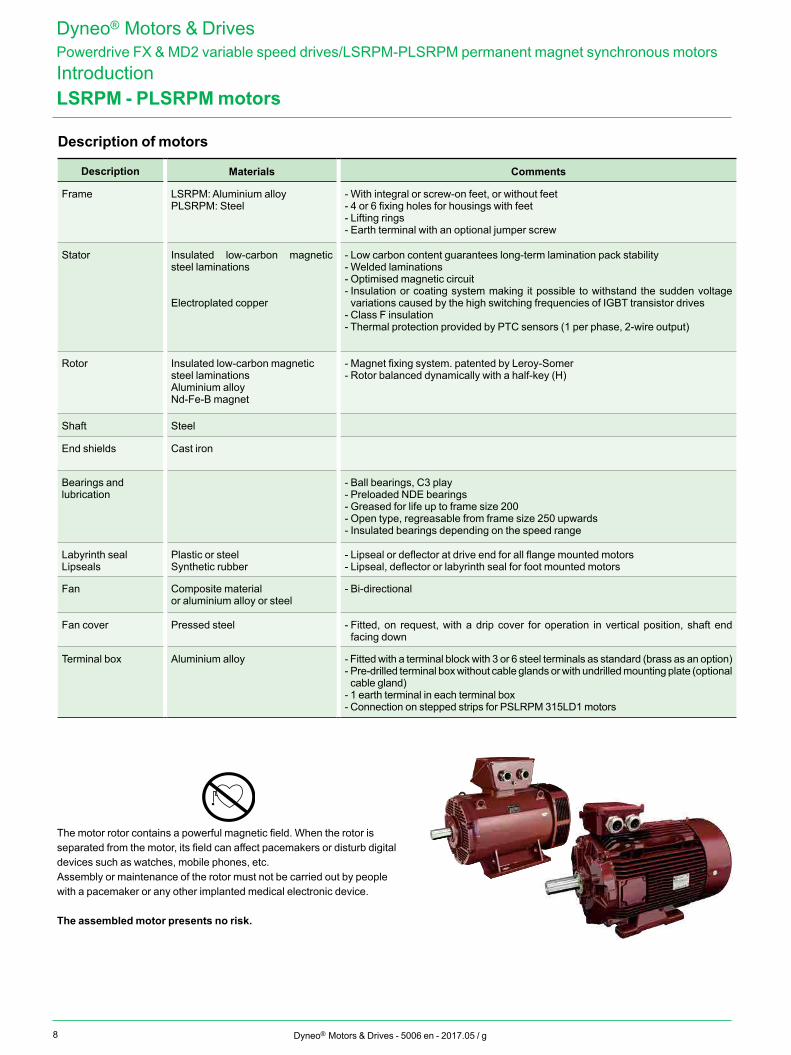
Description of motors
Description Materials Comments
Frame LSRPM: Aluminium alloyPLSRPM: Steel
- With integral or screw-on feet, or without feet- 4 or 6 fixing holes for housings with feet- Lifting rings - Earth terminal with an optional jumper screw
Stator Insulated low-carbon magnetic steel laminations
Electroplated copper
- Low carbon content guarantees long-term lamination pack stability- Welded laminations- Optimised magnetic circuit- Insulation or coating system making it possible to withstand the sudden voltage variations caused by the high switching frequencies of IGBT transistor drives
- Class F insulation- Thermal protection provided by PTC sensors (1 per phase, 2-wire output)
Rotor Insulated low-carbon magnetic steel laminationsAluminium alloyNd-Fe-B magnet
- Magnet fixing system. patented by Leroy-Somer- Rotor balanced dynamically with a half-key (H)
Shaft Steel
End shields Cast iron
Bearings and lubrication
- Ball bearings, C3 play- Preloaded NDE bearings- Greased for life up to frame size 200- Open type, regreasable from frame size 250 upwards- Insulated bearings depending on the speed range
Labyrinth sealLipseals
Plastic or steelSynthetic rubber
- Lipseal or deflector at drive end for all flange mounted motors- Lipseal, deflector or labyrinth seal for foot mounted motors
Fan Composite material or aluminium alloy or steel
- Bi-directional
Fan cover Pressed steel - Fitted, on request, with a drip cover for operation in vertical position, shaft end facing down
Terminal box Aluminium alloy - Fitted with a terminal block with 3 or 6 steel terminals as standard (brass as an option)- Pre-drilled terminal box without cable glands or with undrilled mounting plate (optional cable gland)
- 1 earth terminal in each terminal box- Connection on stepped strips for PSLRPM 315LD1 motors
The motor rotor contains a powerful magnetic field. When the rotor is separated from the motor, its field can affect pacemakers or disturb digital devices such as watches, mobile phones, etc.Assembly or maintenance of the rotor must not be carried out by people with a pacemaker or any other implanted medical electronic device.
The assembled motor presents no risk.
9Dyneo® Motors & Drives - 5006 en - 2017.05 / g
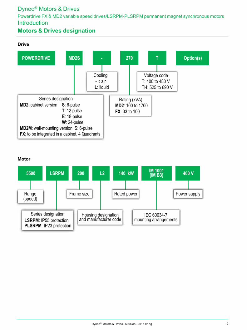
Motors & Drives designation
5500 LSRPM 200 L2 140 kW IM 1001(IM B3) 400 V
Housing designationand manufacturer code
Rated power
IEC 60034-7mounting arrangements
Power supply
Series designationLSRPM: IP55 protectionPLSRPM: IP23 protection
Frame sizeRange(speed)
Voltage codeT: 400 to 480 VTH: 525 to 690 V
Rating (kVA)MD2: 100 to 1700FX: 33 to 100
MD2: cabinet version S: 6-pulse T: 12-pulse E: 18-pulse W: 24-pulseMD2M: wall-mounting version S: 6-pulseFX: to be integrated in a cabinet, 4 Quadrants
MD2S T270 Option(s)-
Cooling- : air
L: liquid
POWERDRIVE
Series designation
Dyneo® Motors & DrivesPowerdrive FX & MD2 variable speed drives/LSRPM-PLSRPM permanent magnet synchronous motorsIntroduction
Drive
Motor
10 Dyneo® Motors & Drives - 5006 en - 2017.05 / g
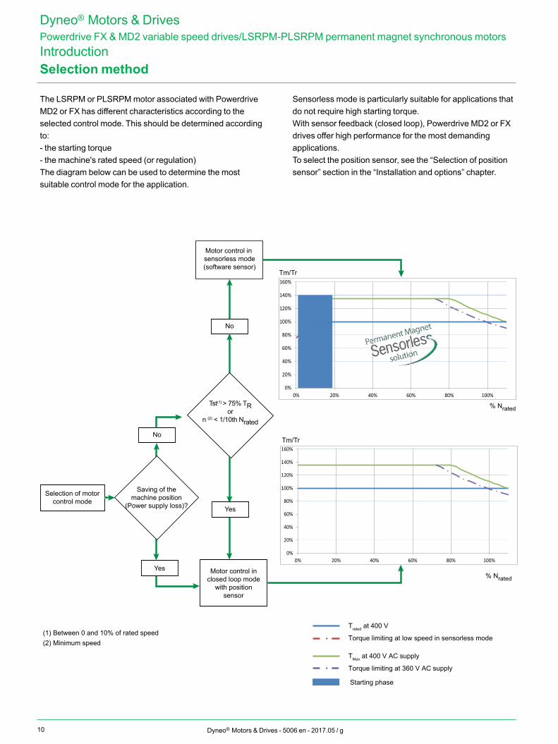
Selection method
Dyneo® Motors & DrivesPowerdrive FX & MD2 variable speed drives/LSRPM-PLSRPM permanent magnet synchronous motorsIntroduction
The LSRPM or PLSRPM motor associated with Powerdrive MD2 or FX has different characteristics according to the selected control mode. This should be determined according to:- the starting torque- the machine's rated speed (or regulation)The diagram below can be used to determine the most suitable control mode for the application.
Sensorless mode is particularly suitable for applications that do not require high starting torque.With sensor feedback (closed loop), Powerdrive MD2 or FX drives offer high performance for the most demanding applications.To select the position sensor, see the “Selection of position sensor” section in the “Installation and options” chapter.
0%
20%
40%
60%
80%
100%
120%
140%
160%
0% 20% 40% 60% 80% 100%
60%
Tm/Tr
(1) Between 0 and 10% of rated speed(2) Minimum speed
Saving of themachine position
(Power supply loss)?
Selection of motorcontrol mode
Tst(1) > 75% TRor
n (2) < 1/10th Nrated
No
Yes
No
Yes
Motor control in sensorless mode(software sensor)
Motor control inclosed loop mode
with positionsensor
Starting phase
Tm/Tr
% Nrated
% Nrated
Trated at 400 V
Torque limiting at low speed in sensorless mode
TMax at 400 V AC supply
Torque limiting at 360 V AC supply
0%
20%
40%
60%
80%
100%
120%
140%
160%
0% 20% 40% 80% 100%
11Dyneo® Motors & Drives - 5006 en - 2017.05 / g
Selection method
Dyneo® Motors & DrivesPowerdrive FX & MD2 variable speed drives/LSRPM-PLSRPM permanent magnet synchronous motorsIntroduction
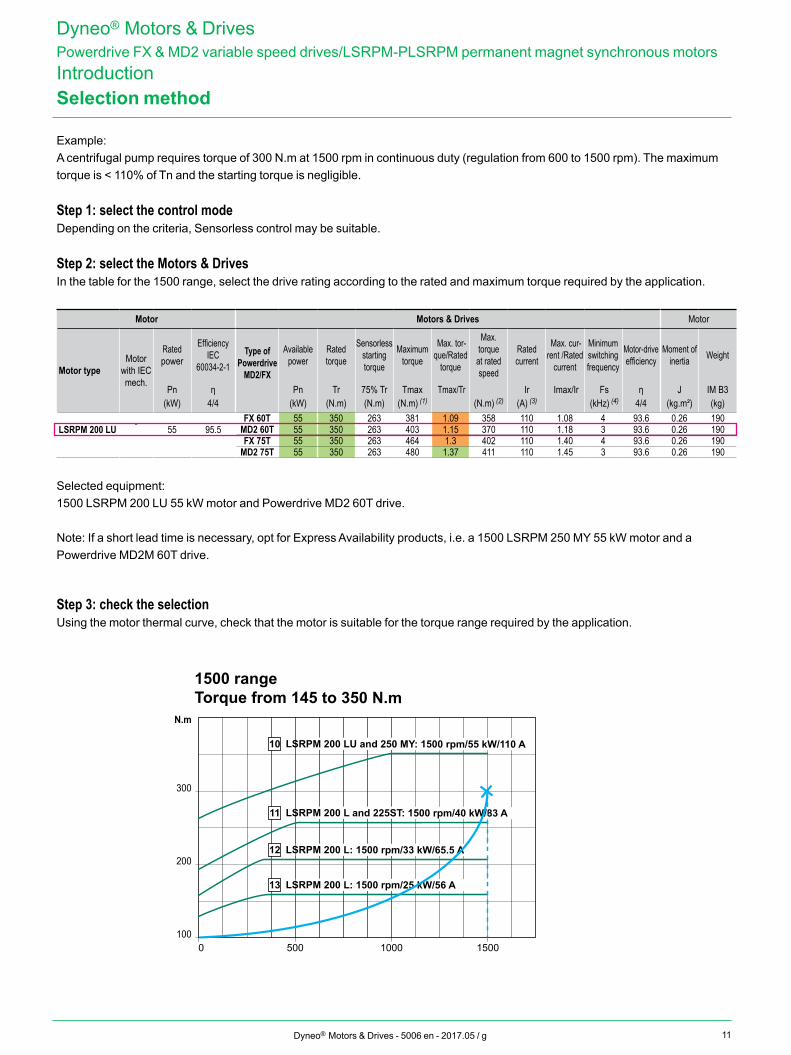
Example:A centrifugal pump requires torque of 300 N.m at 1500 rpm in continuous duty (regulation from 600 to 1500 rpm). The maximum torque is < 110% of Tn and the starting torque is negligible.
Step 1: select the control modeDepending on the criteria, Sensorless control may be suitable.
Step 2: select the Motors & DrivesIn the table for the 1500 range, select the drive rating according to the rated and maximum torque required by the application.
Step 3: check the selectionUsing the motor thermal curve, check that the motor is suitable for the torque range required by the application.
Selected equipment:1500 LSRPM 200 LU 55 kW motor and Powerdrive MD2 60T drive.
Note: If a short lead time is necessary, opt for Express Availability products, i.e. a 1500 LSRPM 250 MY 55 kW motor and a Powerdrive MD2M 60T drive.
100
200
300
N.m
0 500 1000 1500
10 LSRPM 200 LU and 250 MY: 1500 rpm/55 kW/110 A
11 LSRPM 200 L and 225ST: 1500 rpm/40 kW/83 A
12 LSRPM 200 L: 1500 rpm/33 kW/65.5 A
13 LSRPM 200 L: 1500 rpm/25 kW/56 A
1500 rangeTorque from 145 to 350 N.m
Motor Motors & Drives Motor
Motor typeMotor
with IEC mech.
Rated power
Efficiency IEC
60034-2-1Type of
Powerdrive MD2/FX
Available power
Rated torque
Sensorless starting torque
Maximum torque
Max. tor-que/Rated
torque
Max. torque
at rated speed
Rated current
Max. cur-rent /Rated
current
Minimum switching frequency
Motor-drive efficiency
Moment of inertia Weight
Pn η Pn Tr 75% Tr Tmax Tmax/Tr Ir Imax/Ir Fs η J IM B3(kW) 4/4 (kW) (N.m) (N.m) (N.m) (1) (N.m) (2) (A) (3) (kHz) (4) 4/4 (kg.m²) (kg)
LSRPM 200 LU - 55 95.5FX 60T 55 350 263 381 1.09 358 110 1.08 4 93.6 0.26 190
MD2 60T 55 350 263 403 1.15 370 110 1.18 3 93.6 0.26 190FX 75T 55 350 263 464 1.3 402 110 1.40 4 93.6 0.26 190
MD2 75T 55 350 263 480 1.37 411 110 1.45 3 93.6 0.26 190
12 Dyneo® Motors & Drives - 5006 en - 2017.05 / g
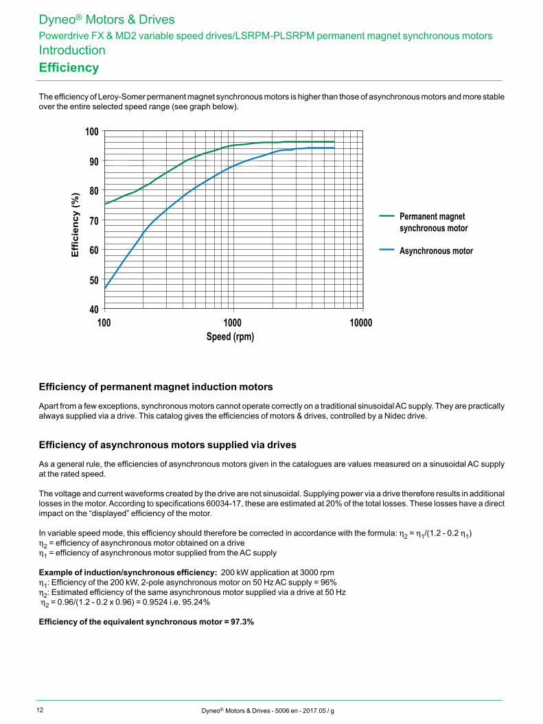
The efficiency of Leroy-Somer permanent magnet synchronous motors is higher than those of asynchronous motors and more stable over the entire selected speed range (see graph below).
40
50
60
70
80
90
100
100 1000 10000Speed (rpm)
Eff
icie
ncy
(%)
Permanent magnet synchronous motor
Asynchronous motor
Efficiency of permanent magnet induction motors
Apart from a few exceptions, synchronous motors cannot operate correctly on a traditional sinusoidal AC supply. They are practically always supplied via a drive. This catalog gives the efficiencies of motors & drives, controlled by a Nidec drive.
Efficiency of asynchronous motors supplied via drives
As a general rule, the efficiencies of asynchronous motors given in the catalogues are values measured on a sinusoidal AC supply at the rated speed.
The voltage and current waveforms created by the drive are not sinusoidal. Supplying power via a drive therefore results in additional losses in the motor. According to specifications 60034-17, these are estimated at 20% of the total losses. These losses have a direct impact on the “displayed” efficiency of the motor.
In variable speed mode, this efficiency should therefore be corrected in accordance with the formula: h2 = h1/(1.2 - 0.2 h1)h2 = efficiency of asynchronous motor obtained on a driveh1 = efficiency of asynchronous motor supplied from the AC supply
Example of induction/synchronous efficiency: 200 kW application at 3000 rpmh1: Efficiency of the 200 kW, 2-pole asynchronous motor on 50 Hz AC supply = 96%h2: Estimated efficiency of the same asynchronous motor supplied via a drive at 50 Hz h2 = 0.96/(1.2 - 0.2 x 0.96) = 0.9524 i.e. 95.24%
Efficiency of the equivalent synchronous motor = 97.3%
Efficiency
Dyneo® Motors & DrivesPowerdrive FX & MD2 variable speed drives/LSRPM-PLSRPM permanent magnet synchronous motorsIntroduction
13Dyneo® Motors & Drives - 5006 en - 2017.05 / g
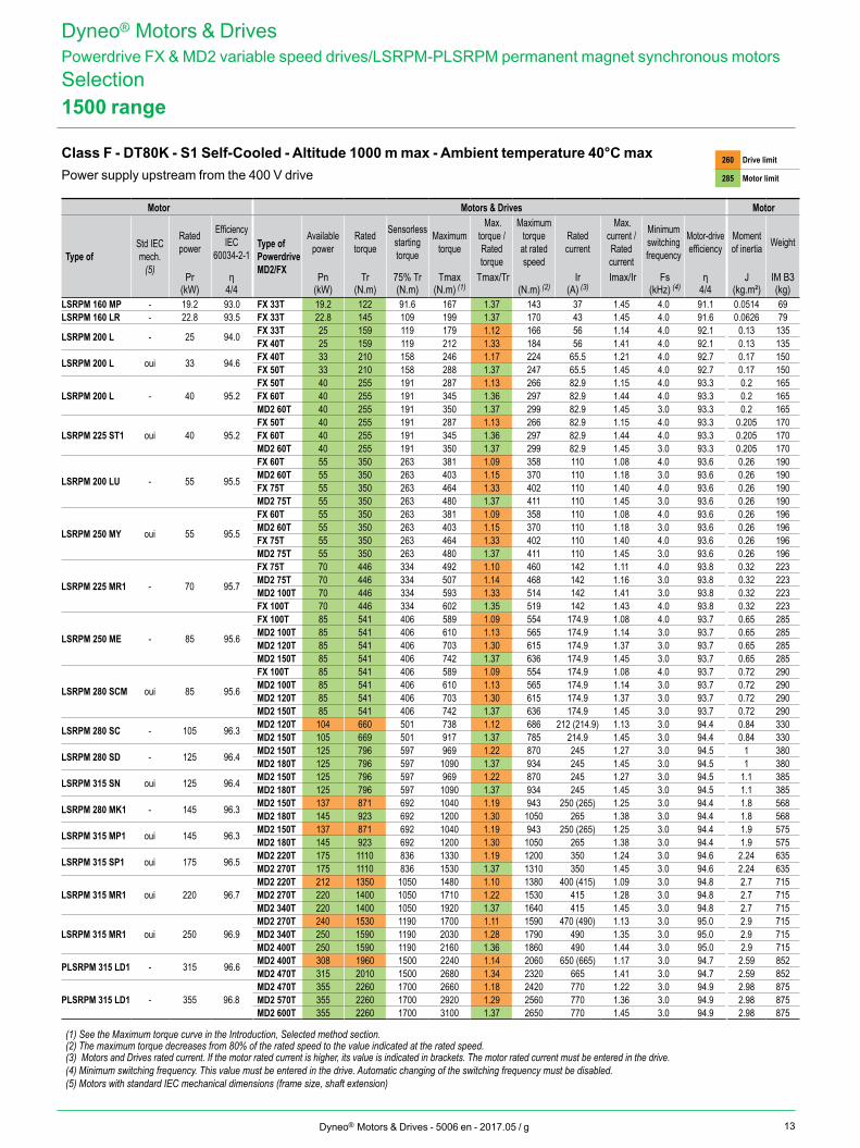
1500 range
Class F - DT80K - S1 Self-Cooled - Altitude 1000 m max - Ambient temperature 40°C maxPower supply upstream from the 400 V drive
260 Drive limit
285 Motor limit
Dyneo® Motors & DrivesPowerdrive FX & MD2 variable speed drives/LSRPM-PLSRPM permanent magnet synchronous motorsSelection
Motor Motors & Drives Motor
Type ofStd IEC mech.
(5)
Rated power
Efficiency IEC
60034-2-1Type of Powerdrive MD2/FX
Available power
Rated torque
Sensorless starting torque
Maximum torque
Max. torque /Rated torque
Maximum torque
at rated speed
Rated current
Max. current /Rated current
Minimum switching frequency
Motor-drive efficiency
Moment of inertia Weight
Pr η Pn Tr 75% Tr Tmax Tmax/Tr Ir Imax/Ir Fs η J IM B3(kW) 4/4 (kW) (N.m) (N.m) (N.m) (1) (N.m) (2) (A) (3) (kHz) (4) 4/4 (kg.m²) (kg)
LSRPM 160 MP - 19.2 93.0 FX 33T 19.2 122 91.6 167 1.37 143 37 1.45 4.0 91.1 0.0514 69LSRPM 160 LR - 22.8 93.5 FX 33T 22.8 145 109 199 1.37 170 43 1.45 4.0 91.6 0.0626 79
LSRPM 200 L - 25 94.0 FX 33T 25 159 119 179 1.12 166 56 1.14 4.0 92.1 0.13 135FX 40T 25 159 119 212 1.33 184 56 1.41 4.0 92.1 0.13 135
LSRPM 200 L oui 33 94.6 FX 40T 33 210 158 246 1.17 224 65.5 1.21 4.0 92.7 0.17 150FX 50T 33 210 158 288 1.37 247 65.5 1.45 4.0 92.7 0.17 150
LSRPM 200 L - 40 95.2FX 50T 40 255 191 287 1.13 266 82.9 1.15 4.0 93.3 0.2 165FX 60T 40 255 191 345 1.36 297 82.9 1.44 4.0 93.3 0.2 165MD2 60T 40 255 191 350 1.37 299 82.9 1.45 3.0 93.3 0.2 165
LSRPM 225 ST1 oui 40 95.2FX 50T 40 255 191 287 1.13 266 82.9 1.15 4.0 93.3 0.205 170FX 60T 40 255 191 345 1.36 297 82.9 1.44 4.0 93.3 0.205 170MD2 60T 40 255 191 350 1.37 299 82.9 1.45 3.0 93.3 0.205 170
LSRPM 200 LU - 55 95.5
FX 60T 55 350 263 381 1.09 358 110 1.08 4.0 93.6 0.26 190MD2 60T 55 350 263 403 1.15 370 110 1.18 3.0 93.6 0.26 190FX 75T 55 350 263 464 1.33 402 110 1.40 4.0 93.6 0.26 190MD2 75T 55 350 263 480 1.37 411 110 1.45 3.0 93.6 0.26 190
LSRPM 250 MY oui 55 95.5
FX 60T 55 350 263 381 1.09 358 110 1.08 4.0 93.6 0.26 196MD2 60T 55 350 263 403 1.15 370 110 1.18 3.0 93.6 0.26 196FX 75T 55 350 263 464 1.33 402 110 1.40 4.0 93.6 0.26 196MD2 75T 55 350 263 480 1.37 411 110 1.45 3.0 93.6 0.26 196
LSRPM 225 MR1 - 70 95.7
FX 75T 70 446 334 492 1.10 460 142 1.11 4.0 93.8 0.32 223MD2 75T 70 446 334 507 1.14 468 142 1.16 3.0 93.8 0.32 223MD2 100T 70 446 334 593 1.33 514 142 1.41 3.0 93.8 0.32 223FX 100T 70 446 334 602 1.35 519 142 1.43 4.0 93.8 0.32 223
LSRPM 250 ME - 85 95.6
FX 100T 85 541 406 589 1.09 554 174.9 1.08 4.0 93.7 0.65 285MD2 100T 85 541 406 610 1.13 565 174.9 1.14 3.0 93.7 0.65 285MD2 120T 85 541 406 703 1.30 615 174.9 1.37 3.0 93.7 0.65 285MD2 150T 85 541 406 742 1.37 636 174.9 1.45 3.0 93.7 0.65 285
LSRPM 280 SCM oui 85 95.6
FX 100T 85 541 406 589 1.09 554 174.9 1.08 4.0 93.7 0.72 290MD2 100T 85 541 406 610 1.13 565 174.9 1.14 3.0 93.7 0.72 290MD2 120T 85 541 406 703 1.30 615 174.9 1.37 3.0 93.7 0.72 290MD2 150T 85 541 406 742 1.37 636 174.9 1.45 3.0 93.7 0.72 290
LSRPM 280 SC - 105 96.3 MD2 120T 104 660 501 738 1.12 686 212 (214.9) 1.13 3.0 94.4 0.84 330MD2 150T 105 669 501 917 1.37 785 214.9 1.45 3.0 94.4 0.84 330
LSRPM 280 SD - 125 96.4 MD2 150T 125 796 597 969 1.22 870 245 1.27 3.0 94.5 1 380MD2 180T 125 796 597 1090 1.37 934 245 1.45 3.0 94.5 1 380
LSRPM 315 SN oui 125 96.4 MD2 150T 125 796 597 969 1.22 870 245 1.27 3.0 94.5 1.1 385MD2 180T 125 796 597 1090 1.37 934 245 1.45 3.0 94.5 1.1 385
LSRPM 280 MK1 - 145 96.3 MD2 150T 137 871 692 1040 1.19 943 250 (265) 1.25 3.0 94.4 1.8 568MD2 180T 145 923 692 1200 1.30 1050 265 1.38 3.0 94.4 1.8 568
LSRPM 315 MP1 oui 145 96.3 MD2 150T 137 871 692 1040 1.19 943 250 (265) 1.25 3.0 94.4 1.9 575MD2 180T 145 923 692 1200 1.30 1050 265 1.38 3.0 94.4 1.9 575
LSRPM 315 SP1 oui 175 96.5 MD2 220T 175 1110 836 1330 1.19 1200 350 1.24 3.0 94.6 2.24 635MD2 270T 175 1110 836 1530 1.37 1310 350 1.45 3.0 94.6 2.24 635
LSRPM 315 MR1 oui 220 96.7MD2 220T 212 1350 1050 1480 1.10 1380 400 (415) 1.09 3.0 94.8 2.7 715MD2 270T 220 1400 1050 1710 1.22 1530 415 1.28 3.0 94.8 2.7 715MD2 340T 220 1400 1050 1920 1.37 1640 415 1.45 3.0 94.8 2.7 715
LSRPM 315 MR1 oui 250 96.9MD2 270T 240 1530 1190 1700 1.11 1590 470 (490) 1.13 3.0 95.0 2.9 715MD2 340T 250 1590 1190 2030 1.28 1790 490 1.35 3.0 95.0 2.9 715MD2 400T 250 1590 1190 2160 1.36 1860 490 1.44 3.0 95.0 2.9 715
PLSRPM 315 LD1 - 315 96.6 MD2 400T 308 1960 1500 2240 1.14 2060 650 (665) 1.17 3.0 94.7 2.59 852MD2 470T 315 2010 1500 2680 1.34 2320 665 1.41 3.0 94.7 2.59 852
PLSRPM 315 LD1 - 355 96.8MD2 470T 355 2260 1700 2660 1.18 2420 770 1.22 3.0 94.9 2.98 875MD2 570T 355 2260 1700 2920 1.29 2560 770 1.36 3.0 94.9 2.98 875MD2 600T 355 2260 1700 3100 1.37 2650 770 1.45 3.0 94.9 2.98 875
(1) See the Maximum torque curve in the Introduction, Selected method section.(2) The maximum torque decreases from 80% of the rated speed to the value indicated at the rated speed.(3) Motors and Drives rated current. If the motor rated current is higher, its value is indicated in brackets. The motor rated current must be entered in the drive.(4) Minimum switching frequency. This value must be entered in the drive. Automatic changing of the switching frequency must be disabled.(5) Motors with standard IEC mechanical dimensions (frame size, shaft extension)
14 Dyneo® Motors & Drives - 5006 en - 2017.05 / g
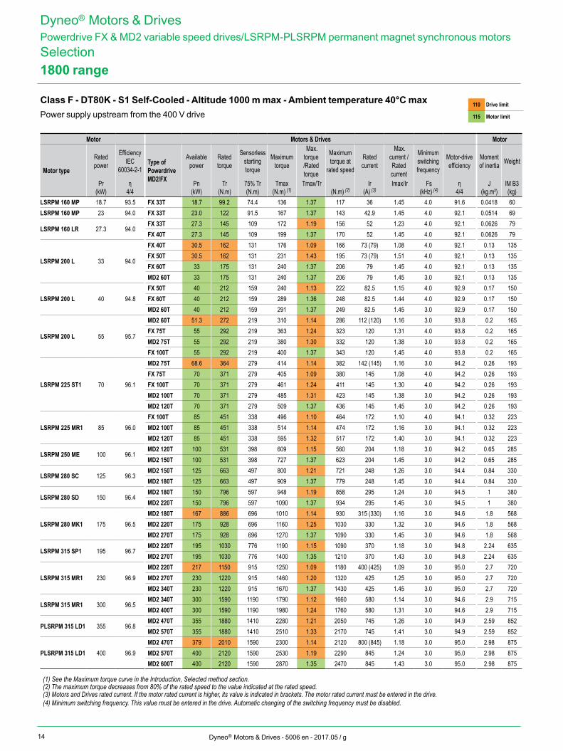
1800 range
Class F - DT80K - S1 Self-Cooled - Altitude 1000 m max - Ambient temperature 40°C maxPower supply upstream from the 400 V drive
110 Drive limit
115 Motor limit
Dyneo® Motors & DrivesPowerdrive FX & MD2 variable speed drives/LSRPM-PLSRPM permanent magnet synchronous motorsSelection
Motor Motors & Drives Motor
Motor type
Rated power
Efficiency IEC
60034-2-1Type of Powerdrive MD2/FX
Available power
Rated torque
Sensorless starting torque
Maximum torque
Max. torque /Rated torque
Maximum torque at
rated speed
Rated current
Max. current /Rated current
Minimum switching frequency
Motor-drive efficiency
Moment of inertia Weight
Pr η Pn Tr 75% Tr Tmax Tmax/Tr Ir Imax/Ir Fs η J IM B3(kW) 4/4 (kW) (N.m) (N.m) (N.m) (1) (N.m) (2) (A) (3) (kHz) (4) 4/4 (kg.m²) (kg)
LSRPM 160 MP 18.7 93.5 FX 33T 18.7 99.2 74.4 136 1.37 117 36 1.45 4.0 91.6 0.0418 60LSRPM 160 MP 23 94.0 FX 33T 23.0 122 91.5 167 1.37 143 42.9 1.45 4.0 92.1 0.0514 69
LSRPM 160 LR 27.3 94.0FX 33T 27.3 145 109 172 1.19 156 52 1.23 4.0 92.1 0.0626 79FX 40T 27.3 145 109 199 1.37 170 52 1.45 4.0 92.1 0.0626 79
LSRPM 200 L 33 94.0
FX 40T 30.5 162 131 176 1.09 166 73 (79) 1.08 4.0 92.1 0.13 135FX 50T 30.5 162 131 231 1.43 195 73 (79) 1.51 4.0 92.1 0.13 135FX 60T 33 175 131 240 1.37 206 79 1.45 4.0 92.1 0.13 135MD2 60T 33 175 131 240 1.37 206 79 1.45 3.0 92.1 0.13 135
LSRPM 200 L 40 94.8FX 50T 40 212 159 240 1.13 222 82.5 1.15 4.0 92.9 0.17 150FX 60T 40 212 159 289 1.36 248 82.5 1.44 4.0 92.9 0.17 150MD2 60T 40 212 159 291 1.37 249 82.5 1.45 3.0 92.9 0.17 150
LSRPM 200 L 55 95.7
MD2 60T 51.3 272 219 310 1.14 286 112 (120) 1.16 3.0 93.8 0.2 165FX 75T 55 292 219 363 1.24 323 120 1.31 4.0 93.8 0.2 165MD2 75T 55 292 219 380 1.30 332 120 1.38 3.0 93.8 0.2 165FX 100T 55 292 219 400 1.37 343 120 1.45 4.0 93.8 0.2 165
LSRPM 225 ST1 70 96.1
MD2 75T 68.6 364 279 414 1.14 382 142 (145) 1.16 3.0 94.2 0.26 193FX 75T 70 371 279 405 1.09 380 145 1.08 4.0 94.2 0.26 193FX 100T 70 371 279 461 1.24 411 145 1.30 4.0 94.2 0.26 193MD2 100T 70 371 279 485 1.31 423 145 1.38 3.0 94.2 0.26 193MD2 120T 70 371 279 509 1.37 436 145 1.45 3.0 94.2 0.26 193
LSRPM 225 MR1 85 96.0FX 100T 85 451 338 496 1.10 464 172 1.10 4.0 94.1 0.32 223MD2 100T 85 451 338 514 1.14 474 172 1.16 3.0 94.1 0.32 223MD2 120T 85 451 338 595 1.32 517 172 1.40 3.0 94.1 0.32 223
LSRPM 250 ME 100 96.1MD2 120T 100 531 398 609 1.15 560 204 1.18 3.0 94.2 0.65 285MD2 150T 100 531 398 727 1.37 623 204 1.45 3.0 94.2 0.65 285
LSRPM 280 SC 125 96.3MD2 150T 125 663 497 800 1.21 721 248 1.26 3.0 94.4 0.84 330MD2 180T 125 663 497 909 1.37 779 248 1.45 3.0 94.4 0.84 330
LSRPM 280 SD 150 96.4MD2 180T 150 796 597 948 1.19 858 295 1.24 3.0 94.5 1 380MD2 220T 150 796 597 1090 1.37 934 295 1.45 3.0 94.5 1 380
LSRPM 280 MK1 175 96.5MD2 180T 167 886 696 1010 1.14 930 315 (330) 1.16 3.0 94.6 1.8 568MD2 220T 175 928 696 1160 1.25 1030 330 1.32 3.0 94.6 1.8 568MD2 270T 175 928 696 1270 1.37 1090 330 1.45 3.0 94.6 1.8 568
LSRPM 315 SP1 195 96.7MD2 220T 195 1030 776 1190 1.15 1090 370 1.18 3.0 94.8 2.24 635MD2 270T 195 1030 776 1400 1.35 1210 370 1.43 3.0 94.8 2.24 635
LSRPM 315 MR1 230 96.9MD2 220T 217 1150 915 1250 1.09 1180 400 (425) 1.09 3.0 95.0 2.7 720MD2 270T 230 1220 915 1460 1.20 1320 425 1.25 3.0 95.0 2.7 720MD2 340T 230 1220 915 1670 1.37 1430 425 1.45 3.0 95.0 2.7 720
LSRPM 315 MR1 300 96.5MD2 340T 300 1590 1190 1790 1.12 1660 580 1.14 3.0 94.6 2.9 715MD2 400T 300 1590 1190 1980 1.24 1760 580 1.31 3.0 94.6 2.9 715
PLSRPM 315 LD1 355 96.8MD2 470T 355 1880 1410 2280 1.21 2050 745 1.26 3.0 94.9 2.59 852MD2 570T 355 1880 1410 2510 1.33 2170 745 1.41 3.0 94.9 2.59 852
PLSRPM 315 LD1 400 96.9MD2 470T 379 2010 1590 2300 1.14 2120 800 (845) 1.18 3.0 95.0 2.98 875MD2 570T 400 2120 1590 2530 1.19 2290 845 1.24 3.0 95.0 2.98 875MD2 600T 400 2120 1590 2870 1.35 2470 845 1.43 3.0 95.0 2.98 875
(1) See the Maximum torque curve in the Introduction, Selected method section.(2) The maximum torque decreases from 80% of the rated speed to the value indicated at the rated speed.(3) Motors and Drives rated current. If the motor rated current is higher, its value is indicated in brackets. The motor rated current must be entered in the drive.(4) Minimum switching frequency. This value must be entered in the drive. Automatic changing of the switching frequency must be disabled.
15Dyneo® Motors & Drives - 5006 en - 2017.05 / g
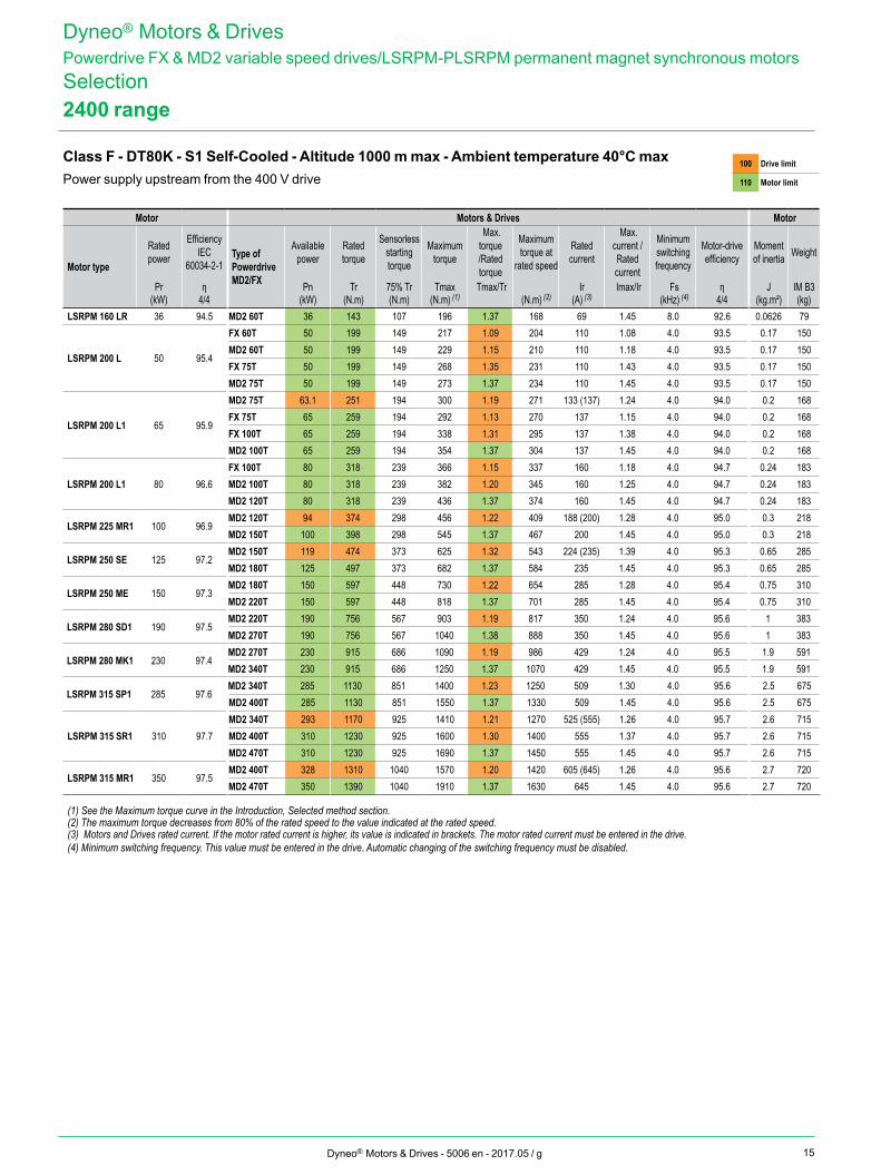
2400 range
Class F - DT80K - S1 Self-Cooled - Altitude 1000 m max - Ambient temperature 40°C maxPower supply upstream from the 400 V drive
100 Drive limit
110 Motor limit
Dyneo® Motors & DrivesPowerdrive FX & MD2 variable speed drives/LSRPM-PLSRPM permanent magnet synchronous motorsSelection
Motor Motors & Drives Motor
Motor type
Rated power
Efficiency IEC
60034-2-1Type of Powerdrive MD2/FX
Available power
Rated torque
Sensorless starting torque
Maximum torque
Max. torque /Rated torque
Maximum torque at
rated speed
Rated current
Max. current /Rated current
Minimum switching frequency
Motor-drive efficiency
Moment of inertia Weight
Pr η Pn Tr 75% Tr Tmax Tmax/Tr Ir Imax/Ir Fs η J IM B3(kW) 4/4 (kW) (N.m) (N.m) (N.m) (1) (N.m) (2) (A) (3) (kHz) (4) 4/4 (kg.m²) (kg)
LSRPM 160 LR 36 94.5 MD2 60T 36 143 107 196 1.37 168 69 1.45 8.0 92.6 0.0626 79
LSRPM 200 L 50 95.4
FX 60T 50 199 149 217 1.09 204 110 1.08 4.0 93.5 0.17 150MD2 60T 50 199 149 229 1.15 210 110 1.18 4.0 93.5 0.17 150FX 75T 50 199 149 268 1.35 231 110 1.43 4.0 93.5 0.17 150MD2 75T 50 199 149 273 1.37 234 110 1.45 4.0 93.5 0.17 150
LSRPM 200 L1 65 95.9
MD2 75T 63.1 251 194 300 1.19 271 133 (137) 1.24 4.0 94.0 0.2 168FX 75T 65 259 194 292 1.13 270 137 1.15 4.0 94.0 0.2 168FX 100T 65 259 194 338 1.31 295 137 1.38 4.0 94.0 0.2 168MD2 100T 65 259 194 354 1.37 304 137 1.45 4.0 94.0 0.2 168
LSRPM 200 L1 80 96.6FX 100T 80 318 239 366 1.15 337 160 1.18 4.0 94.7 0.24 183MD2 100T 80 318 239 382 1.20 345 160 1.25 4.0 94.7 0.24 183MD2 120T 80 318 239 436 1.37 374 160 1.45 4.0 94.7 0.24 183
LSRPM 225 MR1 100 96.9MD2 120T 94 374 298 456 1.22 409 188 (200) 1.28 4.0 95.0 0.3 218MD2 150T 100 398 298 545 1.37 467 200 1.45 4.0 95.0 0.3 218
LSRPM 250 SE 125 97.2MD2 150T 119 474 373 625 1.32 543 224 (235) 1.39 4.0 95.3 0.65 285MD2 180T 125 497 373 682 1.37 584 235 1.45 4.0 95.3 0.65 285
LSRPM 250 ME 150 97.3MD2 180T 150 597 448 730 1.22 654 285 1.28 4.0 95.4 0.75 310MD2 220T 150 597 448 818 1.37 701 285 1.45 4.0 95.4 0.75 310
LSRPM 280 SD1 190 97.5MD2 220T 190 756 567 903 1.19 817 350 1.24 4.0 95.6 1 383MD2 270T 190 756 567 1040 1.38 888 350 1.45 4.0 95.6 1 383
LSRPM 280 MK1 230 97.4MD2 270T 230 915 686 1090 1.19 986 429 1.24 4.0 95.5 1.9 591MD2 340T 230 915 686 1250 1.37 1070 429 1.45 4.0 95.5 1.9 591
LSRPM 315 SP1 285 97.6MD2 340T 285 1130 851 1400 1.23 1250 509 1.30 4.0 95.6 2.5 675MD2 400T 285 1130 851 1550 1.37 1330 509 1.45 4.0 95.6 2.5 675
LSRPM 315 SR1 310 97.7MD2 340T 293 1170 925 1410 1.21 1270 525 (555) 1.26 4.0 95.7 2.6 715MD2 400T 310 1230 925 1600 1.30 1400 555 1.37 4.0 95.7 2.6 715MD2 470T 310 1230 925 1690 1.37 1450 555 1.45 4.0 95.7 2.6 715
LSRPM 315 MR1 350 97.5MD2 400T 328 1310 1040 1570 1.20 1420 605 (645) 1.26 4.0 95.6 2.7 720MD2 470T 350 1390 1040 1910 1.37 1630 645 1.45 4.0 95.6 2.7 720
(1) See the Maximum torque curve in the Introduction, Selected method section.(2) The maximum torque decreases from 80% of the rated speed to the value indicated at the rated speed.(3) Motors and Drives rated current. If the motor rated current is higher, its value is indicated in brackets. The motor rated current must be entered in the drive.(4) Minimum switching frequency. This value must be entered in the drive. Automatic changing of the switching frequency must be disabled.
16 Dyneo® Motors & Drives - 5006 en - 2017.05 / g
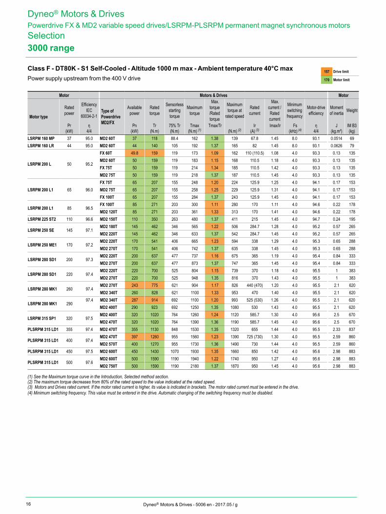
3000 range
Class F - DT80K - S1 Self-Cooled - Altitude 1000 m max - Ambient temperature 40°C maxPower supply upstream from the 400 V drive
157 Drive limit
170 Motor limit
Dyneo® Motors & DrivesPowerdrive FX & MD2 variable speed drives/LSRPM-PLSRPM permanent magnet synchronous motorsSelection
Motor Motors & Drives Motor
Motor type
Rated power
Efficiency IEC
60034-2-1Type of Powerdrive MD2/FX
Available power
Rated torque
Sensorless starting torque
Maximum torque
Max. torque /Rated torque
Maximum torque at
rated speed
Rated current
Max. current /Rated current
Minimum switching frequency
Motor-drive efficiency
Moment of inertia Weight
Pr η Pn Tr 75% Tr Tmax Tmax/Tr Ir Imax/Ir Fs η J IM B3(kW) 4/4 (kW) (N.m) (N.m) (N.m) (1) (N.m) (2) (A) (3) (kHz) (4) 4/4 (kg.m²) (kg)
LSRPM 160 MP 37 95.0 MD2 60T 37 118 88.4 162 1.38 139 67.8 1.45 8.0 93.1 0.0514 69LSRPM 160 LR 44 95.0 MD2 60T 44 140 105 192 1.37 165 82 1.45 8.0 93.1 0.0626 79
LSRPM 200 L 50 95.2
FX 60T 49.8 159 119 173 1.09 162 110 (110.5) 1.08 4.0 93.3 0.13 135MD2 60T 50 159 119 183 1.15 168 110.5 1.18 4.0 93.3 0.13 135FX 75T 50 159 119 214 1.34 185 110.5 1.42 4.0 93.3 0.13 135MD2 75T 50 159 119 218 1.37 187 110.5 1.45 4.0 93.3 0.13 135
LSRPM 200 L1 65 96.0FX 75T 65 207 155 248 1.20 224 125.9 1.25 4.0 94.1 0.17 153MD2 75T 65 207 155 258 1.25 229 125.9 1.31 4.0 94.1 0.17 153FX 100T 65 207 155 284 1.37 243 125.9 1.45 4.0 94.1 0.17 153
LSRPM 200 L1 85 96.5FX 100T 85 271 203 300 1.11 280 170 1.11 4.0 94.6 0.22 178MD2 120T 85 271 203 361 1.33 313 170 1.41 4.0 94.6 0.22 178
LSRPM 225 ST2 110 96.6 MD2 150T 110 350 263 480 1.37 411 215 1.45 4.0 94.7 0.24 195
LSRPM 250 SE 145 97.1MD2 180T 145 462 346 565 1.22 506 284.7 1.28 4.0 95.2 0.57 265MD2 220T 145 462 346 633 1.37 542 284.7 1.45 4.0 95.2 0.57 265
LSRPM 250 ME1 170 97.2MD2 220T 170 541 406 665 1.23 594 338 1.29 4.0 95.3 0.65 288MD2 270T 170 541 406 742 1.37 635 338 1.45 4.0 95.3 0.65 288
LSRPM 280 SD1 200 97.3MD2 220T 200 637 477 737 1.16 675 365 1.19 4.0 95.4 0.84 333MD2 270T 200 637 477 873 1.37 747 365 1.45 4.0 95.4 0.84 333
LSRPM 280 SD1 220 97.4MD2 220T 220 700 525 804 1.15 739 370 1.18 4.0 95.5 1 383MD2 270T 220 700 525 948 1.35 816 370 1.43 4.0 95.5 1 383
LSRPM 280 MK1 260 97.4MD2 270T 243 775 621 904 1.17 826 440 (470) 1.20 4.0 95.5 2.1 620MD2 340T 260 828 621 1100 1.33 953 470 1.40 4.0 95.5 2.1 620
LSRPM 280 MK1 29097.4 MD2 340T 287 914 692 1100 1.20 993 525 (530) 1.26 4.0 95.5 2.1 620
MD2 400T 290 923 692 1250 1.35 1080 530 1.43 4.0 95.5 2.1 620
LSRPM 315 SP1 320 97.5MD2 400T 320 1020 764 1260 1.24 1120 585.7 1.30 4.0 95.6 2.5 670MD2 470T 320 1020 764 1390 1.36 1190 585.7 1.45 4.0 95.6 2.5 670
PLSRPM 315 LD1 355 97.4 MD2 470T 355 1130 848 1530 1.35 1320 655 1.44 4.0 95.5 2.33 837
PLSRPM 315 LD1 400 97.4MD2 470T 397 1260 955 1560 1.23 1390 725 (730) 1.30 4.0 95.5 2.59 860MD2 570T 400 1270 955 1730 1.36 1490 730 1.44 4.0 95.5 2.59 860
PLSRPM 315 LD1 450 97.5 MD2 600T 450 1430 1070 1930 1.35 1660 850 1.42 4.0 95.6 2.98 883
PLSRPM 315 LD1 500 97.6MD2 600T 500 1590 1190 1940 1.22 1740 950 1.27 4.0 95.6 2.98 883MD2 750T 500 1590 1190 2180 1.37 1870 950 1.45 4.0 95.6 2.98 883
(1) See the Maximum torque curve in the Introduction, Selected method section.(2) The maximum torque decreases from 80% of the rated speed to the value indicated at the rated speed.(3) Motors and Drives rated current. If the motor rated current is higher, its value is indicated in brackets. The motor rated current must be entered in the drive.(4) Minimum switching frequency. This value must be entered in the drive. Automatic changing of the switching frequency must be disabled.
17Dyneo® Motors & Drives - 5006 en - 2017.05 / g
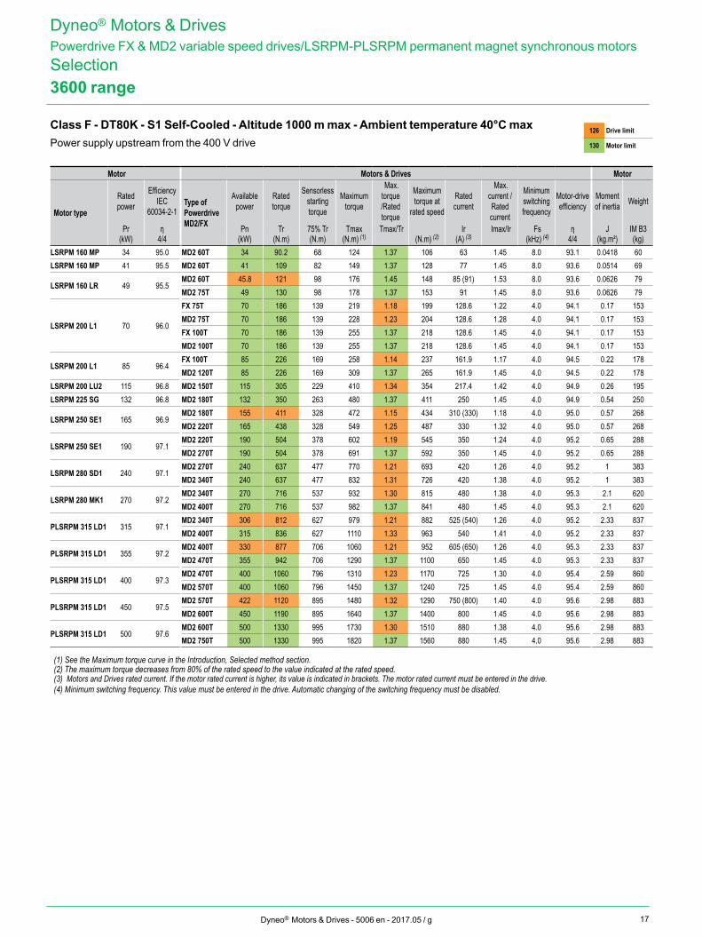
3600 range
Class F - DT80K - S1 Self-Cooled - Altitude 1000 m max - Ambient temperature 40°C maxPower supply upstream from the 400 V drive
126 Drive limit
130 Motor limit
Dyneo® Motors & DrivesPowerdrive FX & MD2 variable speed drives/LSRPM-PLSRPM permanent magnet synchronous motorsSelection
Motor Motors & Drives Motor
Motor type
Rated power
Efficiency IEC
60034-2-1Type of Powerdrive MD2/FX
Available power
Rated torque
Sensorless starting torque
Maximum torque
Max. torque /Rated torque
Maximum torque at
rated speed
Rated current
Max. current /Rated current
Minimum switching frequency
Motor-drive efficiency
Moment of inertia Weight
Pr η Pn Tr 75% Tr Tmax Tmax/Tr Ir Imax/Ir Fs η J IM B3(kW) 4/4 (kW) (N.m) (N.m) (N.m) (1) (N.m) (2) (A) (3) (kHz) (4) 4/4 (kg.m²) (kg)
LSRPM 160 MP 34 95.0 MD2 60T 34 90.2 68 124 1.37 106 63 1.45 8.0 93.1 0.0418 60LSRPM 160 MP 41 95.5 MD2 60T 41 109 82 149 1.37 128 77 1.45 8.0 93.6 0.0514 69
LSRPM 160 LR 49 95.5MD2 60T 45.8 121 98 176 1.45 148 85 (91) 1.53 8.0 93.6 0.0626 79MD2 75T 49 130 98 178 1.37 153 91 1.45 8.0 93.6 0.0626 79
LSRPM 200 L1 70 96.0
FX 75T 70 186 139 219 1.18 199 128.6 1.22 4.0 94.1 0.17 153MD2 75T 70 186 139 228 1.23 204 128.6 1.28 4.0 94.1 0.17 153FX 100T 70 186 139 255 1.37 218 128.6 1.45 4.0 94.1 0.17 153MD2 100T 70 186 139 255 1.37 218 128.6 1.45 4.0 94.1 0.17 153
LSRPM 200 L1 85 96.4FX 100T 85 226 169 258 1.14 237 161.9 1.17 4.0 94.5 0.22 178MD2 120T 85 226 169 309 1.37 265 161.9 1.45 4.0 94.5 0.22 178
LSRPM 200 LU2 115 96.8 MD2 150T 115 305 229 410 1.34 354 217.4 1.42 4.0 94.9 0.26 195LSRPM 225 SG 132 96.8 MD2 180T 132 350 263 480 1.37 411 250 1.45 4.0 94.9 0.54 250
LSRPM 250 SE1 165 96.9MD2 180T 155 411 328 472 1.15 434 310 (330) 1.18 4.0 95.0 0.57 268MD2 220T 165 438 328 549 1.25 487 330 1.32 4.0 95.0 0.57 268
LSRPM 250 SE1 190 97.1MD2 220T 190 504 378 602 1.19 545 350 1.24 4.0 95.2 0.65 288MD2 270T 190 504 378 691 1.37 592 350 1.45 4.0 95.2 0.65 288
LSRPM 280 SD1 240 97.1MD2 270T 240 637 477 770 1.21 693 420 1.26 4.0 95.2 1 383MD2 340T 240 637 477 832 1.31 726 420 1.38 4.0 95.2 1 383
LSRPM 280 MK1 270 97.2MD2 340T 270 716 537 932 1.30 815 480 1.38 4.0 95.3 2.1 620MD2 400T 270 716 537 982 1.37 841 480 1.45 4.0 95.3 2.1 620
PLSRPM 315 LD1 315 97.1MD2 340T 306 812 627 979 1.21 882 525 (540) 1.26 4.0 95.2 2.33 837MD2 400T 315 836 627 1110 1.33 963 540 1.41 4.0 95.2 2.33 837
PLSRPM 315 LD1 355 97.2MD2 400T 330 877 706 1060 1.21 952 605 (650) 1.26 4.0 95.3 2.33 837MD2 470T 355 942 706 1290 1.37 1100 650 1.45 4.0 95.3 2.33 837
PLSRPM 315 LD1 400 97.3MD2 470T 400 1060 796 1310 1.23 1170 725 1.30 4.0 95.4 2.59 860MD2 570T 400 1060 796 1450 1.37 1240 725 1.45 4.0 95.4 2.59 860
PLSRPM 315 LD1 450 97.5MD2 570T 422 1120 895 1480 1.32 1290 750 (800) 1.40 4.0 95.6 2.98 883MD2 600T 450 1190 895 1640 1.37 1400 800 1.45 4.0 95.6 2.98 883
PLSRPM 315 LD1 500 97.6MD2 600T 500 1330 995 1730 1.30 1510 880 1.38 4.0 95.6 2.98 883MD2 750T 500 1330 995 1820 1.37 1560 880 1.45 4.0 95.6 2.98 883
(1) See the Maximum torque curve in the Introduction, Selected method section.(2) The maximum torque decreases from 80% of the rated speed to the value indicated at the rated speed.(3) Motors and Drives rated current. If the motor rated current is higher, its value is indicated in brackets. The motor rated current must be entered in the drive.(4) Minimum switching frequency. This value must be entered in the drive. Automatic changing of the switching frequency must be disabled.
18 Dyneo® Motors & Drives - 5006 en - 2017.05 / g
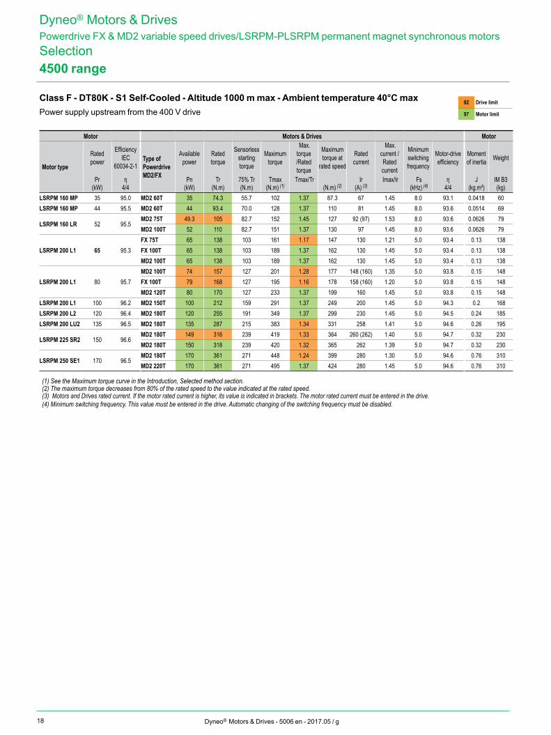
4500 range
Class F - DT80K - S1 Self-Cooled - Altitude 1000 m max - Ambient temperature 40°C maxPower supply upstream from the 400 V drive
92 Drive limit
97 Motor limit
Dyneo® Motors & DrivesPowerdrive FX & MD2 variable speed drives/LSRPM-PLSRPM permanent magnet synchronous motorsSelection
Motor Motors & Drives Motor
Motor type
Rated power
Efficiency IEC
60034-2-1Type of Powerdrive MD2/FX
Available power
Rated torque
Sensorless starting torque
Maximum torque
Max. torque /Rated torque
Maximum torque at
rated speed
Rated current
Max. current /Rated current
Minimum switching frequency
Motor-drive efficiency
Moment of inertia Weight
Pr η Pn Tr 75% Tr Tmax Tmax/Tr Ir Imax/Ir Fs η J IM B3(kW) 4/4 (kW) (N.m) (N.m) (N.m) (1) (N.m) (2) (A) (3) (kHz) (4) 4/4 (kg.m²) (kg)
LSRPM 160 MP 35 95.0 MD2 60T 35 74.3 55.7 102 1.37 87.3 67 1.45 8.0 93.1 0.0418 60LSRPM 160 MP 44 95.5 MD2 60T 44 93.4 70.0 128 1.37 110 81 1.45 8.0 93.6 0.0514 69
LSRPM 160 LR 52 95.5MD2 75T 49.3 105 82.7 152 1.45 127 92 (97) 1.53 8.0 93.6 0.0626 79MD2 100T 52 110 82.7 151 1.37 130 97 1.45 8.0 93.6 0.0626 79
LSRPM 200 L1 65 95.3FX 75T 65 138 103 161 1.17 147 130 1.21 5.0 93.4 0.13 138FX 100T 65 138 103 189 1.37 162 130 1.45 5.0 93.4 0.13 138MD2 100T 65 138 103 189 1.37 162 130 1.45 5.0 93.4 0.13 138
LSRPM 200 L1 80 95.7MD2 100T 74 157 127 201 1.28 177 148 (160) 1.35 5.0 93.8 0.15 148FX 100T 79 168 127 195 1.16 178 158 (160) 1.20 5.0 93.8 0.15 148MD2 120T 80 170 127 233 1.37 199 160 1.45 5.0 93.8 0.15 148
LSRPM 200 L1 100 96.2 MD2 150T 100 212 159 291 1.37 249 200 1.45 5.0 94.3 0.2 168LSRPM 200 L2 120 96.4 MD2 180T 120 255 191 349 1.37 299 230 1.45 5.0 94.5 0.24 185LSRPM 200 LU2 135 96.5 MD2 180T 135 287 215 383 1.34 331 258 1.41 5.0 94.6 0.26 195
LSRPM 225 SR2 150 96.6MD2 180T 149 316 239 419 1.33 364 260 (262) 1.40 5.0 94.7 0.32 230MD2 180T 150 318 239 420 1.32 365 262 1.39 5.0 94.7 0.32 230
LSRPM 250 SE1 170 96.5MD2 180T 170 361 271 448 1.24 399 280 1.30 5.0 94.6 0.76 310MD2 220T 170 361 271 495 1.37 424 280 1.45 5.0 94.6 0.76 310
(1) See the Maximum torque curve in the Introduction, Selected method section.(2) The maximum torque decreases from 80% of the rated speed to the value indicated at the rated speed.(3) Motors and Drives rated current. If the motor rated current is higher, its value is indicated in brackets. The motor rated current must be entered in the drive.(4) Minimum switching frequency. This value must be entered in the drive. Automatic changing of the switching frequency must be disabled.
19Dyneo® Motors & Drives - 5006 en - 2017.05 / g
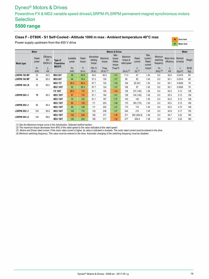
5500 range
Class F - DT80K - S1 Self-Cooled - Altitude 1000 m max - Ambient temperature 40°C maxPower supply upstream from the 400 V drive
85 Drive limit
97 Motor limit
Dyneo® Motors & DrivesPowerdrive FX & MD2 variable speed drives/LSRPM-PLSRPM permanent magnet synchronous motorsSelection
Motor Motors & Drives Motor
Motor type
Rated power
Efficiency IEC
60034-2-1Type of Powerdrive MD2/FX
Available power
Rated torque
Sensorless starting torque
Maximum torque
Max. torque /Rated torque
Maximum torque at
rated speed
Rated current
Max. current /Rated current
Minimum switching frequency
Motor-drive efficiency
Moment of inertia Weight
Pr η Pn Tr 75% Tr Tmax Tmax/Tr Ir Imax/Ir Fs η J IM B3(kW) 4/4 (kW) (N.m) (N.m) (N.m) (1) (N.m) (2) (A) (3) (kHz) (4) 4/4 (kg.m²) (kg)
LSRPM 160 MP 35 94.5 MD2 60T 35 60.8 45.6 83.4 1.37 71.4 67 1.45 8.0 92.6 0.0418 60LSRPM 160 MP 44 95.0 MD2 60T 44 76.4 57.3 105 1.37 90 82 1.45 8.0 93.1 0.0514 69
LSRPM 160 LR 52 95.0MD2 75T 49.3 85.6 67.7 124 1.45 104 92 (97) 1.53 8.0 93.1 0.0626 79MD2 100T 52 90.3 67.7 124 1.37 106 97 1.45 8.0 93.1 0.0626 79
LSRPM 200 L1 70 95.2FX 100T 68.5 119 91.1 155 1.30 136 137 (140) 1.38 6.0 93.3 0.13 138MD2 100T 67 116 91.1 164 1.41 139 134 (140) 1.49 6.0 93.3 0.13 138MD2 120T 70 122 91.1 167 1.37 143 140 1.45 6.0 93.3 0.13 138
LSRPM 200 L1 85 95.4MD2 150T 80 139 111 203 1.46 170 160 (170) 1.54 6.0 93.5 0.15 148MD2 150T 85 148 111 202 1.37 173 170 1.45 6.0 93.5 0.15 148
LSRPM 200 L1 100 95.8 MD2 180T 100 174 130 238 1.37 204 210 1.45 6.0 93.9 0.17 153
LSRPM 200 L2 140 96.6MD2 180T 132 229 182 317 1.38 271 250 (264.9) 1.46 6.0 94.7 0.22 180MD2 180T 140 243 182 317 1.30 277 264.9 1.38 6.0 94.7 0.22 180
(1) See the Maximum torque curve in the Introduction, Selected method section.(2) The maximum torque decreases from 80% of the rated speed to the value indicated at the rated speed.(3) Motors and Drives rated current. If the motor rated current is higher, its value is indicated in brackets. The motor rated current must be entered in the drive.(4) Minimum switching frequency. This value must be entered in the drive. Automatic changing of the switching frequency must be disabled.
20
88
89
90
91
92
93
94
95
96
97
400
300
500
600
700
800
0 500 1000 1500 0 500 1000 1500
rpm rpm
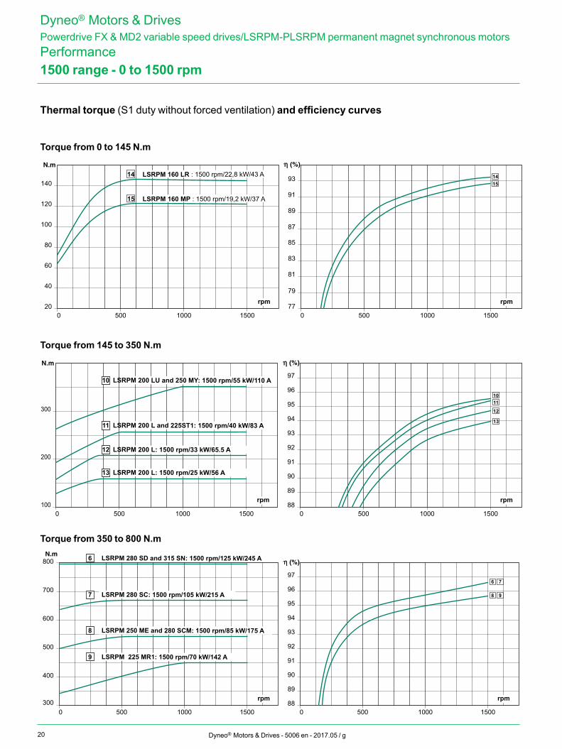
6 LSRPM 280 SD and 315 SN: 1500 rpm/125 kW/245 A
7 LSRPM 280 SC: 1500 rpm/105 kW/215 A
8 LSRPM 250 ME and 280 SCM: 1500 rpm/85 kW/175 A
9 LSRPM 225 MR1: 1500 rpm/70 kW/142 A
6 7
98
20
40
60
80
100
120
140
77
79
81
83
85
87
89
91
93
0 500 1000 1500 0 500 1000 1500
1514
15 LSRPM 160 MP : 1500 rpm/19,2 kW/37 A
14 LSRPM 160 LR : 1500 rpm/22,8 kW/43 A
rpm rpm
88
89
90
91
92
93
94
95
96
97
100
200
300
0 500 1000 1500 0 500 1000 1500
rpm rpm
10 LSRPM 200 LU and 250 MY: 1500 rpm/55 kW/110 A
11 LSRPM 200 L and 225ST1: 1500 rpm/40 kW/83 A
12 LSRPM 200 L: 1500 rpm/33 kW/65.5 A
13 LSRPM 200 L: 1500 rpm/25 kW/56 A
101112
13
Dyneo® Motors & Drives - 5006 en - 2017.05 / g
Torque from 0 to 145 N.m
Torque from 145 to 350 N.m
Torque from 350 to 800 N.m
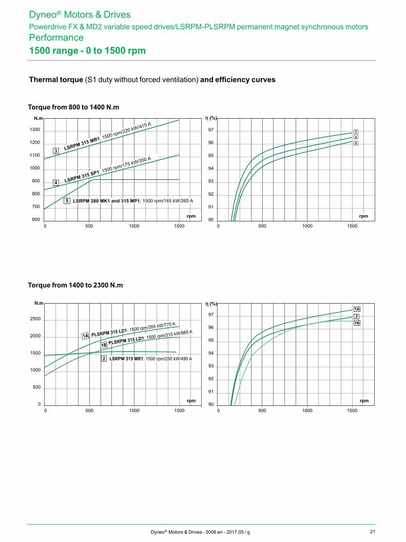
1500 range - 0 to 1500 rpm
Dyneo® Motors & DrivesPowerdrive FX & MD2 variable speed drives/LSRPM-PLSRPM permanent magnet synchronous motorsPerformance
Thermal torque (S1 duty without forced ventilation) and efficiency curves
21
600
700
800
900
1000
1100
1200
1300
90
91
92
93
94
95
96
97
0 500 1000 15000 500 1000 1500
rpm rpm
3 LSRPM 315 MR1: 1500 rpm/220 kW/415 A
4 LSRPM 315 SP1: 1500 rpm/175 kW/350 A
5 LSRPM 280 MK1 and 315 MP1: 1500 rpm/145 kW/265 A
3
54
0
500
1000
1500
2000
2500
90
91
92
93
94
95
96
97
0 500 1000 15000 500 1000 1500
1A PLSRPM 315 LD1: 1500 rpm/355 kW/770 A
1B PLSRPM 315 LD1: 1500 rpm/315 kW/665 A
2 LSRPM 315 MR1: 1500 rpm/250 kW/490 A
2
1A
1B
rpmrpm
Dyneo® Motors & Drives - 5006 en - 2017.05 / g
1500 range - 0 to 1500 rpm
Torque from 800 to 1400 N.m
Torque from 1400 to 2300 N.m
Dyneo® Motors & DrivesPowerdrive FX & MD2 variable speed drives/LSRPM-PLSRPM permanent magnet synchronous motorsPerformance
Thermal torque (S1 duty without forced ventilation) and efficiency curves
22
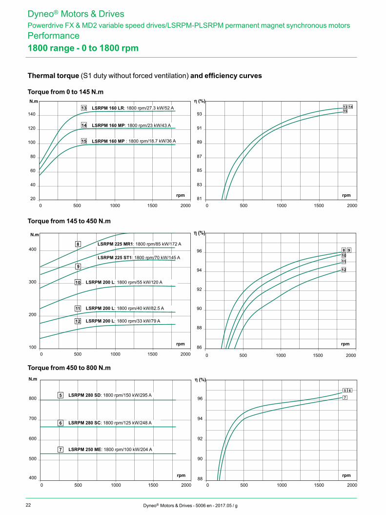
15
15 LSRPM 160 MP : 1800 rpm/18.7 kW/36 A
0 500 1000 1500 2000 0 500 1000 1500 200020
40
60
80
100
120
140
81
83
85
87
89
91
93
rpm rpm
1413
14 LSRPM 160 MP: 1800 rpm/23 kW/43 A
13 LSRPM 160 LR: 1800 rpm/27.3 kW/52 A
86
88
90
92
94
96
100
200
300
400
0 500 1000 1500 2000 0 500 1000 1500 2000
rpm rpm
9
LSRPM 225 ST1: 1800 rpm/70 kW/145 A
10 LSRPM 200 L: 1800 rpm/55 kW/120 A
11 LSRPM 200 L: 1800 rpm/40 kW/82.5 A
12 LSRPM 200 L: 1800 rpm/33 kW/79 A
8 91011
12
8 LSRPM 225 MR1: 1800 rpm/85 kW/172 A
88
90
92
94
96
500
400
600
700
800
0 500 1000 1500 2000 0 500 1000 1500 2000
rpm rpm
5 LSRPM 280 SD: 1800 rpm/150 kW/295 A
6 LSRPM 280 SC: 1800 rpm/125 kW/248 A
7 LSRPM 250 ME: 1800 rpm/100 kW/204 A
5 6
7
Dyneo® Motors & Drives - 5006 en - 2017.05 / g
1800 range - 0 to 1800 rpm
Dyneo® Motors & DrivesPowerdrive FX & MD2 variable speed drives/LSRPM-PLSRPM permanent magnet synchronous motorsPerformance
Torque from 0 to 145 N.m
Torque from 145 to 450 N.m
Torque from 450 to 800 N.m
Thermal torque (S1 duty without forced ventilation) and efficiency curves
23
93
91
95
97
92
94
96
700
800
900
1000
1100
1200
0 500 1000 1500 2000 0 500 1000 1500 2000
rpm rpm
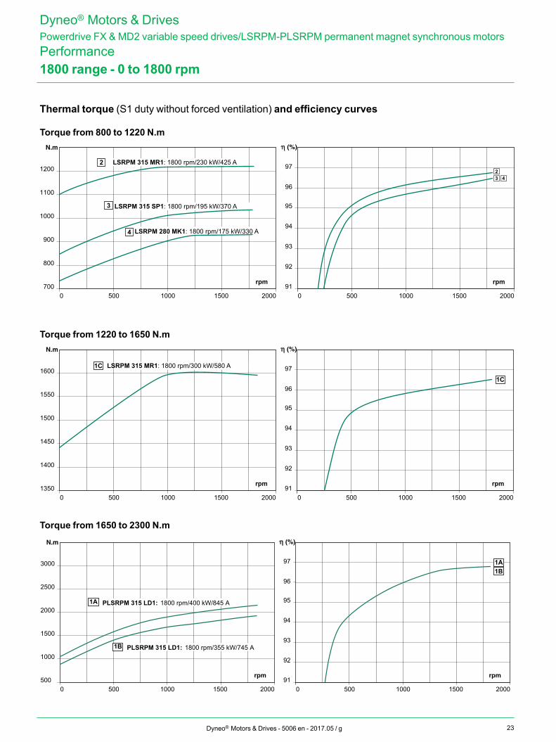
2 LSRPM 315 MR1: 1800 rpm/230 kW/425 A
3 LSRPM 315 SP1: 1800 rpm/195 kW/370 A
4
23 4
LSRPM 280 MK1: 1800 rpm/175 kW/330 A
93
91
95
97
92
94
96
1350
1400
1450
1500
1550
1600
0 500 1000 1500 2000 0 500 1000 1500 2000
rpm rpm
1C
1C
LSRPM 315 MR1: 1800 rpm/300 kW/580 A
93
91
95
97
92
94
96
500
1000
1500
2000
2500
3000
0 500 1000 1500 2000 0 500 1000 1500 2000
1A1B
1B PLSRPM 315 LD1: 1800 rpm/355 kW/745 A
1A PLSRPM 315 LD1: 1800 rpm/400 kW/845 A
rpm rpm
Dyneo® Motors & Drives - 5006 en - 2017.05 / g
1800 range - 0 to 1800 rpm
Dyneo® Motors & DrivesPowerdrive FX & MD2 variable speed drives/LSRPM-PLSRPM permanent magnet synchronous motorsPerformance
Torque from 800 to 1220 N.m
Torque from 1220 to 1650 N.m
Torque from 1650 to 2300 N.m
Thermal torque (S1 duty without forced ventilation) and efficiency curves
24
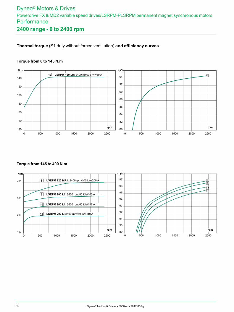
20
40
60
80
100
120
140
80
82
84
86
88
90
92
94
0 500 1000 1500 2000 25000 500 1000 1500 2000 2500
rpm rpm
1313 LSRPM 160 LR: 2400 rpm/36 kW/69 A
89
90
91
92
93
94
95
96
97
0 500 1000 1500 2000 25000 500 1000 1500 2000 2500100
200
300
400
rpm rpm
8 LSRPM 225 MR1: 2400 rpm/100 kW/200 A
9 LSRPM 200 L1: 2400 rpm/80 kW/160 A
10 LSRPM 200 L1: 2400 rpm/65 kW/137 A
11 LSRPM 200 L: 2400 rpm/50 kW/110 A
89
1011
Dyneo® Motors & Drives - 5006 en - 2017.05 / g
2400 range - 0 to 2400 rpm
Torque from 0 to 145 N.m
Torque from 145 to 400 N.m
Dyneo® Motors & DrivesPowerdrive FX & MD2 variable speed drives/LSRPM-PLSRPM permanent magnet synchronous motorsPerformance
Thermal torque (S1 duty without forced ventilation) and efficiency curves
25
89
90
91
92
93
94
95
96
97
400
500
600
700
0 500 1000 1500 2000 25000 500 1000 1500 2000 2500
rpm rpm
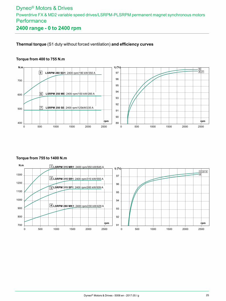
6 LSRPM 250 ME: 2400 rpm/150 kW/285 A
7 LSRPM 250 SE: 2400 rpm/125kW/235 A
5 LSRPM 280 SD1: 2400 rpm/190 kW/350 A 56 7
91
92
93
94
95
96
97
700
800
900
1000
1100
1200
1300
0 500 1000 1500 2000 25000 500 1000 1500 2000 2500
rpm rpm
1 2 34
2 LSRPM 315 SR1: 2400 rpm/310 kW/555 A
1 LSRPM 315 MR1: 2400 rpm/350 kW/645 A
3 LSRPM 315 SP1: 2400 rpm/285 kW/509 A
4 LSRPM 280 MK1: 2400 rpm/230 kW/429 A
Dyneo® Motors & Drives - 5006 en - 2017.05 / g
2400 range - 0 to 2400 rpm
Torque from 400 to 755 N.m
Torque from 755 to 1400 N.m
Dyneo® Motors & DrivesPowerdrive FX & MD2 variable speed drives/LSRPM-PLSRPM permanent magnet synchronous motorsPerformance
Thermal torque (S1 duty without forced ventilation) and efficiency curves
26
8120
40
60
80
100
120
140
89
93
87
91
83
85
95
0 1000 2000 30000 1000 2000 3000
rpm rpm
1716
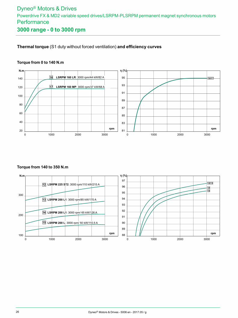
17 LSRPM 160 MP: 3000 rpm/37 kW/68 A
16 LSRPM 160 LR: 3000 rpm/44 kW/82 A
88
89
90
91
92
93
94
95
96
97
0 1000 2000 30000 1000 2000 3000100
200
300
rpm rpm
15
12 13
1412
13 LSRPM 200 L1: 3000 rpm/85 kW/170 A
LSRPM 225 ST2: 3000 rpm/110 kW/215 A
14 LSRPM 200 L1: 3000 rpm/ 65 kW/126 A
15 LSRPM 200 L: 3000 rpm/ 50 kW/110.5 A
Dyneo® Motors & Drives - 5006 en - 2017.05 / g
3000 range - 0 to 3000 rpm
Torque from 0 to 140 N.m
Torque from 140 to 350 N.m
Dyneo® Motors & DrivesPowerdrive FX & MD2 variable speed drives/LSRPM-PLSRPM permanent magnet synchronous motorsPerformance
Thermal torque (S1 duty without forced ventilation) and efficiency curves
27
400
500
600
700
88
89
90
91
92
93
94
95
96
97
0 1000 2000 30000 1000 2000 3000
rpm rpm
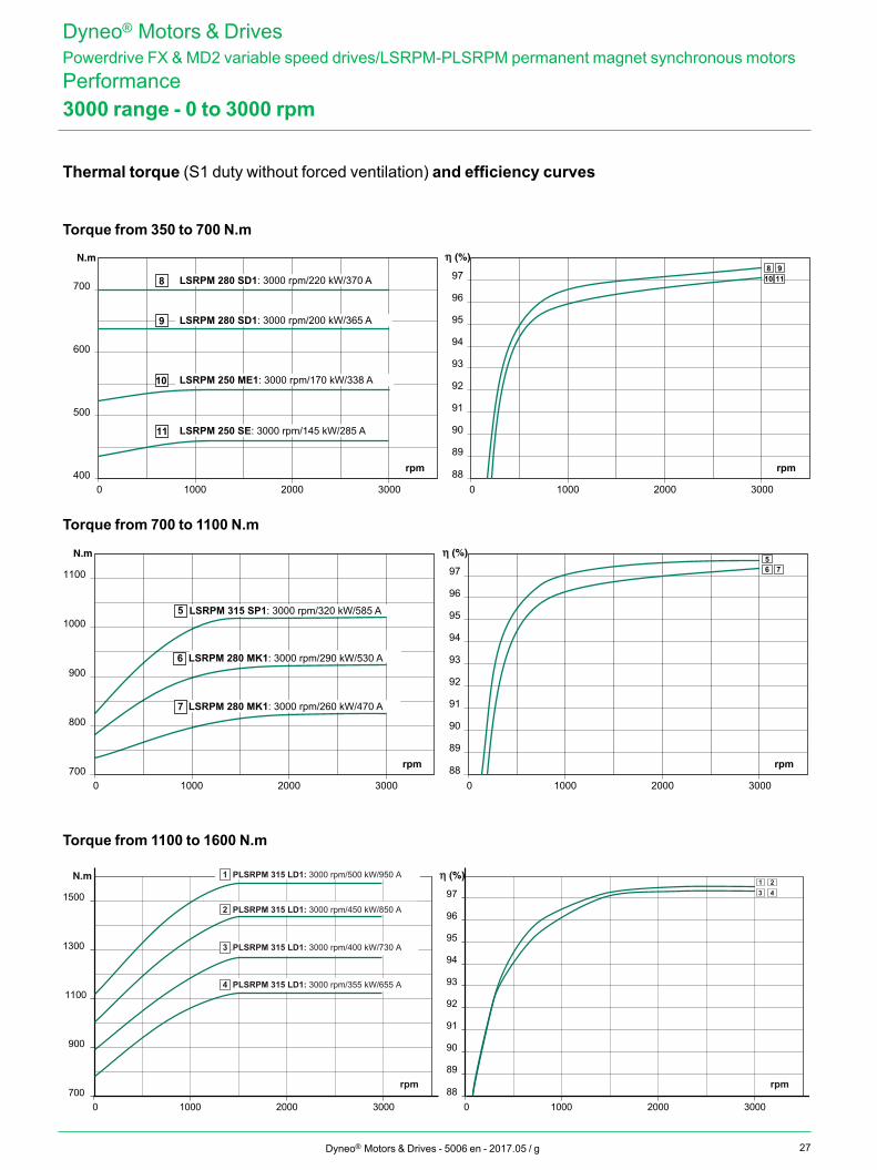
8 910 118 LSRPM 280 SD1: 3000 rpm/220 kW/370 A
9 LSRPM 280 SD1: 3000 rpm/200 kW/365 A
10 LSRPM 250 ME1: 3000 rpm/170 kW/338 A
11 LSRPM 250 SE: 3000 rpm/145 kW/285 A
700
800
900
1000
1100
88
89
90
91
92
93
94
95
96
97
0 1000 2000 30000 1000 2000 3000
rpm rpm
576
6 LSRPM 280 MK1: 3000 rpm/290 kW/530 A
5 LSRPM 315 SP1: 3000 rpm/320 kW/585 A
7 LSRPM 280 MK1: 3000 rpm/260 kW/470 A
700
900
1100
1300
1500
88
89
90
91
92
93
94
95
96
97
0 1000 2000 30000 1000 2000 3000
1 23 4
PLSRPM 315 LD1: 3000 rpm/500 kW/950 A 1
2 PLSRPM 315 LD1: 3000 rpm/450 kW/850 A
PLSRPM 315 LD1: 3000 rpm/400 kW/730 A 3
4 PLSRPM 315 LD1: 3000 rpm/355 kW/655 A
rpm rpm
Dyneo® Motors & Drives - 5006 en - 2017.05 / g
3000 range - 0 to 3000 rpm
Torque from 350 to 700 N.m
Torque from 700 to 1100 N.m
Torque from 1100 to 1600 N.m
Dyneo® Motors & DrivesPowerdrive FX & MD2 variable speed drives/LSRPM-PLSRPM permanent magnet synchronous motorsPerformance
Thermal torque (S1 duty without forced ventilation) and efficiency curves
28
20
40
60
80
100
120
87
89
91
93
95
88
90
92
94
96
0 300020001000 40000 300020001000 4000
rpm rpm
161514
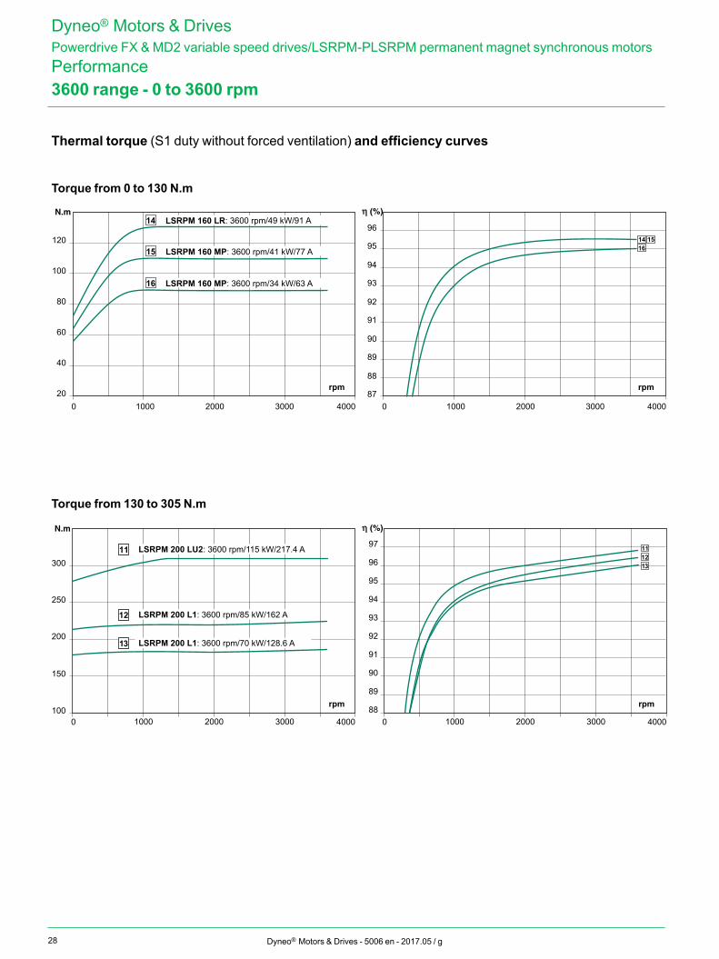
16 LSRPM 160 MP: 3600 rpm/34 kW/63 A
15 LSRPM 160 MP: 3600 rpm/41 kW/77 A
14 LSRPM 160 LR: 3600 rpm/49 kW/91 A
0 1000 2000 3000 4000 0 1000 2000 3000 4000100
150
200
250
300
89
91
93
95
88
90
92
94
96
97
rpm rpm
111213
11 LSRPM 200 LU2: 3600 rpm/115 kW/217.4 A
12 LSRPM 200 L1: 3600 rpm/85 kW/162 A
13 LSRPM 200 L1: 3600 rpm/70 kW/128.6 A
Dyneo® Motors & Drives - 5006 en - 2017.05 / g
3600 range - 0 to 3600 rpm
Torque from 0 to 130 N.m
Torque from 130 to 305 N.m
Dyneo® Motors & DrivesPowerdrive FX & MD2 variable speed drives/LSRPM-PLSRPM permanent magnet synchronous motorsPerformance
Thermal torque (S1 duty without forced ventilation) and efficiency curves
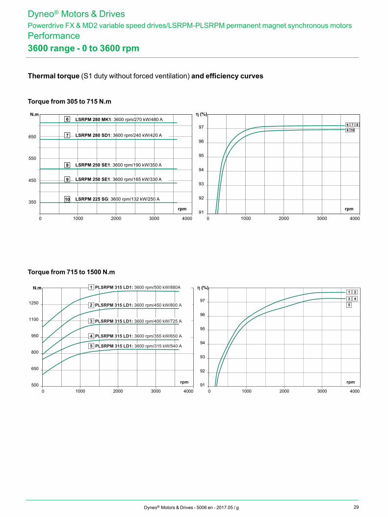
29
0 1000 2000 3000 4000 0 1000 2000 3000 4000
350
450
550
650
91
92
93
94
95
96
97
rpm rpm
6 89 10
7
9 LSRPM 250 SE1: 3600 rpm/165 kW/330 A
10 LSRPM 225 SG: 3600 rpm/132 kW/250 A
8 LSRPM 250 SE1: 3600 rpm/190 kW/350 A
7 LSRPM 280 SD1: 3600 rpm/240 kW/420 A
6 LSRPM 280 MK1: 3600 rpm/270 kW/480 A
0 1000 2000 3000 4000500
650
800
950
1100
1250
0 1000 2000 3000 400091
92
93
94
95
96
972 PLSRPM 315 LD1: 3600 rpm/450 kW/800 A
PLSRPM 315 LD1: 3600 rpm/400 kW/725 A 3
4 PLSRPM 315 LD1: 3600 rpm/355 kW/650 A
5 PLSRPM 315 LD1: 3600 rpm/315 kW/540 A
PLSRPM 315 LD1: 3600 rpm/500 kW/880A 1
3 45
1 2
rpm rpm
Dyneo® Motors & Drives - 5006 en - 2017.05 / g
3600 range - 0 to 3600 rpm
Torque from 305 to 715 N.m
Torque from 715 to 1500 N.m
Dyneo® Motors & DrivesPowerdrive FX & MD2 variable speed drives/LSRPM-PLSRPM permanent magnet synchronous motorsPerformance
Thermal torque (S1 duty without forced ventilation) and efficiency curves
30
0 1000 2000 3000 4000 5000 0 1000 2000 3000 4000 500020
40
60
80
100
87
89
91
93
95
88
90
92
94
96
rpm rpm
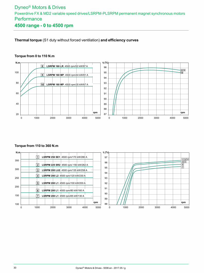
9810
10 LSRPM 160 MP: 4500 rpm/35 kW/67 A
9 LSRPM 160 MP: 4500 rpm/44 kW/81 A
8 LSRPM 160 LR: 4500 rpm/52 kW/97 A
0 2000 3000 40001000 5000 0 2000 3000 40001000 5000100
150
200
250
300
350
88
89
90
91
92
93
94
95
96
97
rpm rpm
32154
67
1 LSRPM 250 SE1: 4500 rpm/170 kW/280 A
2 LSRPM 225 SR2: 4500 rpm/ 150 kW/262 A
3 LSRPM 200 LU2: 4500 rpm/135 kW/258 A
4 LSRPM 200 L2: 4500 rpm/120 kW/230 A
5 LSRPM 200 L1: 4500 rpm/100 kW/200 A
6 LSRPM 200 L1: 4500 rpm/80 kW/160 A
7 LSRPM 200 L1: 4500 rpm/65 kW/130 A
Dyneo® Motors & Drives - 5006 en - 2017.05 / g
Torque from 0 to 110 N.m
Torque from 110 to 360 N.m
Dyneo® Motors & DrivesPowerdrive FX & MD2 variable speed drives/LSRPM-PLSRPM permanent magnet synchronous motorsPerformance4500 range - 0 to 4500 rpm
Thermal torque (S1 duty without forced ventilation) and efficiency curves
31
0 1000 2000 3000 4000 5000 600020
30
40
50
60
70
80
90
0 1000 2000 3000 4000 5000 600087
89
91
93
95
88
90
92
94
96
rpm rpm
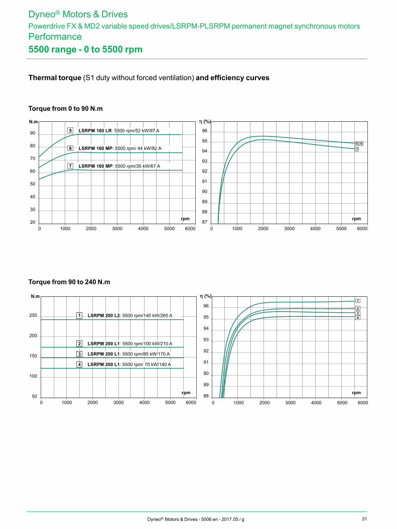
7 LSRPM 160 MP: 5500 rpm/35 kW/67 A
6 LSRPM 160 MP: 5500 rpm/ 44 kW/82 A
5 LSRPM 160 LR: 5500 rpm/52 kW/97 A
765
0 1000 2000 3000 4000 5000 6000 0 1000 2000 3000 4000 5000 600050
100
150
200
250
88
89
90
91
92
93
94
95
96
rpm rpm
32
1
41 LSRPM 200 L2: 5500 rpm/140 kW/265 A
2 LSRPM 200 L1: 5500 rpm/100 kW/210 A
3 LSRPM 200 L1: 5500 rpm/85 kW/170 A
4 LSRPM 200 L1: 5500 rpm/ 70 kW/140 A
Dyneo® Motors & Drives - 5006 en - 2017.05 / g
Torque from 0 to 90 N.m
Torque from 90 to 240 N.m
Dyneo® Motors & DrivesPowerdrive FX & MD2 variable speed drives/LSRPM-PLSRPM permanent magnet synchronous motorsPerformance5500 range - 0 to 5500 rpm
Thermal torque (S1 duty without forced ventilation) and efficiency curves
32
H
W D
Dyneo® Motors & Drives - 5006 en - 2017.05 / g
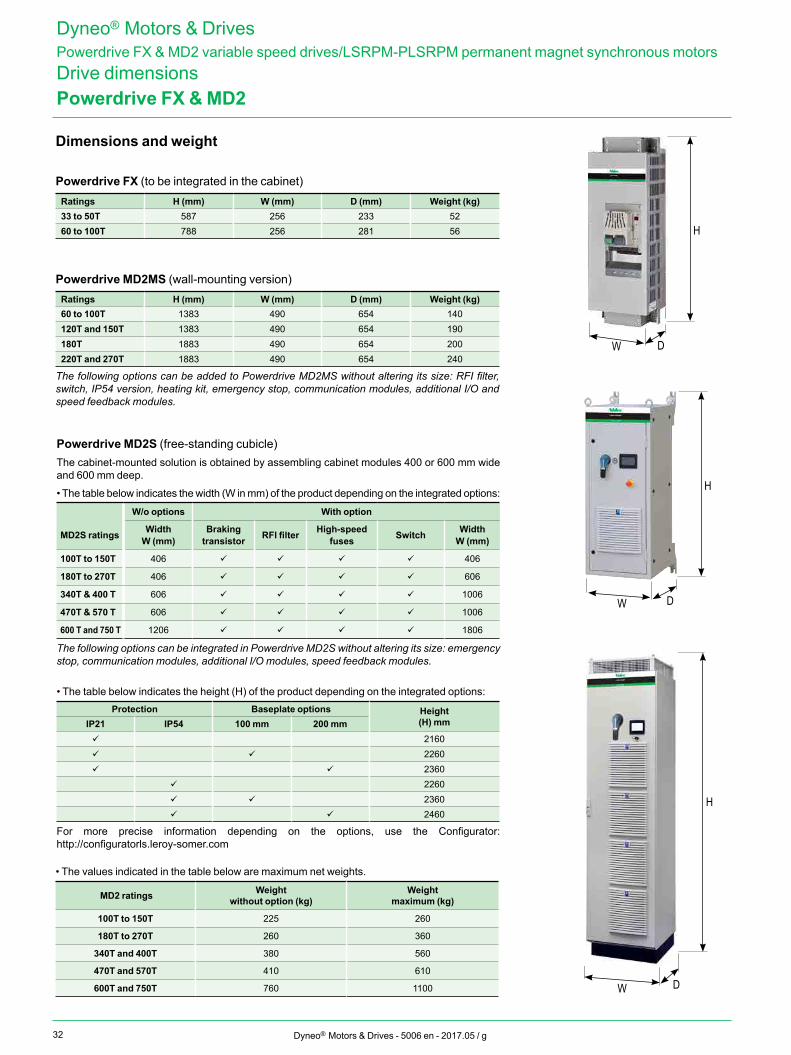
Dimensions and weight
Powerdrive FX (to be integrated in the cabinet)Ratings H (mm) W (mm) D (mm) Weight (kg)33 to 50T 587 256 233 5260 to 100T 788 256 281 56
Powerdrive MD2MS (wall-mounting version)Ratings H (mm) W (mm) D (mm) Weight (kg)60 to 100T 1383 490 654 140120T and 150T 1383 490 654 190180T 1883 490 654 200220T and 270T 1883 490 654 240
The following options can be added to Powerdrive MD2MS without altering its size: RFI filter, switch, IP54 version, heating kit, emergency stop, communication modules, additional I/O and speed feedback modules.
Powerdrive FX & MD2
Dyneo® Motors & DrivesPowerdrive FX & MD2 variable speed drives/LSRPM-PLSRPM permanent magnet synchronous motorsDrive dimensions
Powerdrive MD2S (free-standing cubicle)The cabinet-mounted solution is obtained by assembling cabinet modules 400 or 600 mm wide and 600 mm deep.
• The table below indicates the width (W in mm) of the product depending on the integrated options:
W/o options With option
MD2S ratings WidthW (mm)
Braking transistor RFI filter High-speed
fuses Switch WidthW (mm)
100T to 150T 406 406
180T to 270T 406 606
340T & 400 T 606 1006
470T & 570 T 606 1006
600 T and 750 T 1206 1806
The following options can be integrated in Powerdrive MD2S without altering its size: emergency stop, communication modules, additional I/O modules, speed feedback modules.
• The table below indicates the height (H) of the product depending on the integrated options:Protection Baseplate options Height
(H) mmIP21 IP54 100 mm 200 mm 2160 2260 2360
2260 2360 2460
For more precise information depending on the options, use the Configurator: http://configuratorls.leroy-somer.com
• The values indicated in the table below are maximum net weights.
MD2 ratings Weightwithout option (kg)
Weightmaximum (kg)
100T to 150T 225 260
180T to 270T 260 360
340T and 400T 380 560
470T and 570T 410 610
600T and 750T 760 1100
H
W D
H
W D
33Dyneo® Motors & Drives - 5006 en - 2017.05 / g
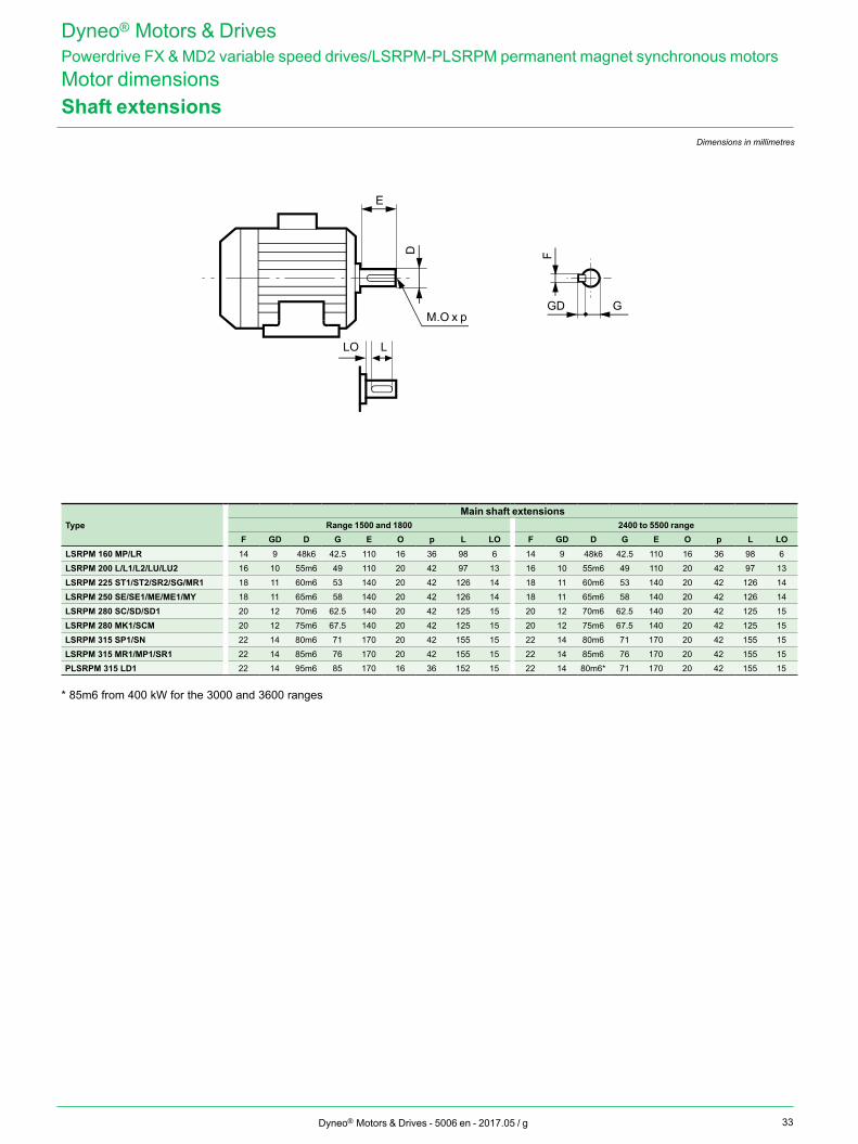
Shaft extensions
TypeMain shaft extensions
Range 1500 and 1800 2400 to 5500 rangeF GD D G E O p L LO F GD D G E O p L LO
LSRPM 160 MP/LR 14 9 48k6 42.5 110 16 36 98 6 14 9 48k6 42.5 110 16 36 98 6LSRPM 200 L/L1/L2/LU/LU2 16 10 55m6 49 110 20 42 97 13 16 10 55m6 49 110 20 42 97 13LSRPM 225 ST1/ST2/SR2/SG/MR1 18 11 60m6 53 140 20 42 126 14 18 11 60m6 53 140 20 42 126 14LSRPM 250 SE/SE1/ME/ME1/MY 18 11 65m6 58 140 20 42 126 14 18 11 65m6 58 140 20 42 126 14LSRPM 280 SC/SD/SD1 20 12 70m6 62.5 140 20 42 125 15 20 12 70m6 62.5 140 20 42 125 15LSRPM 280 MK1/SCM 20 12 75m6 67.5 140 20 42 125 15 20 12 75m6 67.5 140 20 42 125 15LSRPM 315 SP1/SN 22 14 80m6 71 170 20 42 155 15 22 14 80m6 71 170 20 42 155 15LSRPM 315 MR1/MP1/SR1 22 14 85m6 76 170 20 42 155 15 22 14 85m6 76 170 20 42 155 15PLSRPM 315 LD1 22 14 95m6 85 170 16 36 152 15 22 14 80m6* 71 170 20 42 155 15
* 85m6 from 400 kW for the 3000 and 3600 ranges
E
D
M.O x p
F
GD G
LLO
Dimensions in millimetres
Dyneo® Motors & DrivesPowerdrive FX & MD2 variable speed drives/LSRPM-PLSRPM permanent magnet synchronous motorsMotor dimensions
34 Dyneo® Motors & Drives - 5006 en - 2017.05 / g
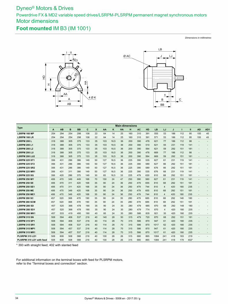
Foot mounted IM B3 (IM 1001)Dimensions in millimetres
TypeMain dimensions
A AB B BB C X AA K HA H AC HD LB LJ J I II AD AD1
LSRPM 160 MP 254 294 254 298 108 22 64 14 25 160 310 391 555 53 186 112 95 155 45LSRPM 160 LR 254 294 254 298 108 22 64 14 25 160 310 391 571 53 186 112 95 155 45
LSRPM 200 L 318 388 305 375 133 35 103 18,5 36 200 390 476 621 77 186 112 98 - -LSRPM 200 L1 318 388 305 375 133 35 103 18,5 36 200 390 510 621 55 231 119 141 - -LSRPM 200 L2 318 388 305 375 133 35 103 18,5 36 200 390 564 621 59 292 151 181 - -LSRPM 200 LU 318 388 305 375 133 35 103 18,5 36 200 390 476 669 77 186 112 98 - -LSRPM 200 LU2 318 388 305 375 133 35 103 18,5 36 200 390 564 669 59 292 151 181 - -
LSRPM 225 ST1 356 431 286 386 149 50 127 18,5 36 225 390 535 627 61 231 119 141 - -LSRPM 225 ST2 356 431 286 386 149 50 127 18,5 36 225 390 589 627 66 292 151 181 - -LSRPM 225 SR2 356 431 286 386 149 50 127 18,5 36 225 390 589 676 66 292 151 181 - -LSRPM 225 MR1 356 431 311 386 149 50 127 18,5 36 225 390 535 676 68 231 119 141 - -LSRPM 225 SG 356 420 286 375 149 30 65 18,5 33 225 479 630 810 68 292 151 181 - -
LSRPM 250 MY 406 470 349 449 168 70 150 24 47 250 390 560 627 61 231 119 141 - -LSRPM 250 SE 406 470 311 420 168 35 90 24 36 250 479 655 810 68 292 151 181 - -LSRPM 250 SE1 406 470 311 420 168 35 90 24 36 250 479 744 810 4 420 180 235 - -LSRPM 250 ME 406 470 349 420 168 35 90 24 36 250 479 655 810 68 292 151 181 - -LSRPM 250 ME1 406 470 349 420 168 35 90 24 36 250 479 744 810 4 420 180 235 - -
LSRPM 280 SC 457 520 368 478 190 35 90 24 35 280 479 685 810 68 292 148 180 - -LSRPM 280 SCM 457 520 368 478 190 35 90 24 35 280 479 685 810 68 292 151 181 - -LSRPM 280 SD 457 520 368 478 190 35 90 24 35 280 479 685 870 68 292 148 180 - -LSRPM 280 SD1 457 520 368 478 190 35 90 24 35 280 479 774 870 4 420 180 235 - -LSRPM 280 MK1 457 533 419 495 190 40 85 24 35 280 586 835 921 35 420 180 235 - -
LSRPM 315 SN 508 594 406 537 216 40 140 28 50 315 479 720 870 68 292 151 181 - -LSRPM 315 SP1 508 594 406 537 216 40 114 28 70 315 586 870 947 61 420 180 235 - -LSRPM 315 SR1 508 594 406 537 216 40 114 28 70 315 586 870 1017 62 420 180 235 - -LSRPM 315 MP1 508 594 457 537 216 40 114 28 70 315 586 870 947 61 420 180 235 - -LSRPM 315 MR1 508 594 457 537 216 40 114 28 70 315 586 870 1017 61 420 180 235 - -
PLSRPM 315 LD1 508 608 508 588 216 40 100 28 26 315 680 865 1084 241 418 183 219 - -PLSRPM 315 LD1 with feed 508 608 508 588 216 40 100 28 26 315 680 865 1084 241 418 179 402*
* 393 with straight feed; 402 with slanted feed
For additional information on the terminal boxes with feed for PLSRPM motors, refer to the “Terminal boxes and connection” section.
Dyneo® Motors & DrivesPowerdrive FX & MD2 variable speed drives/LSRPM-PLSRPM permanent magnet synchronous motorsMotor dimensions
J LJ
LB
Ø AC
x
B C
BB
A
HD
H HA
AB
AA4 Ø K
I II
AD
AD1
35Dyneo® Motors & Drives - 5006 en - 2017.05 / g
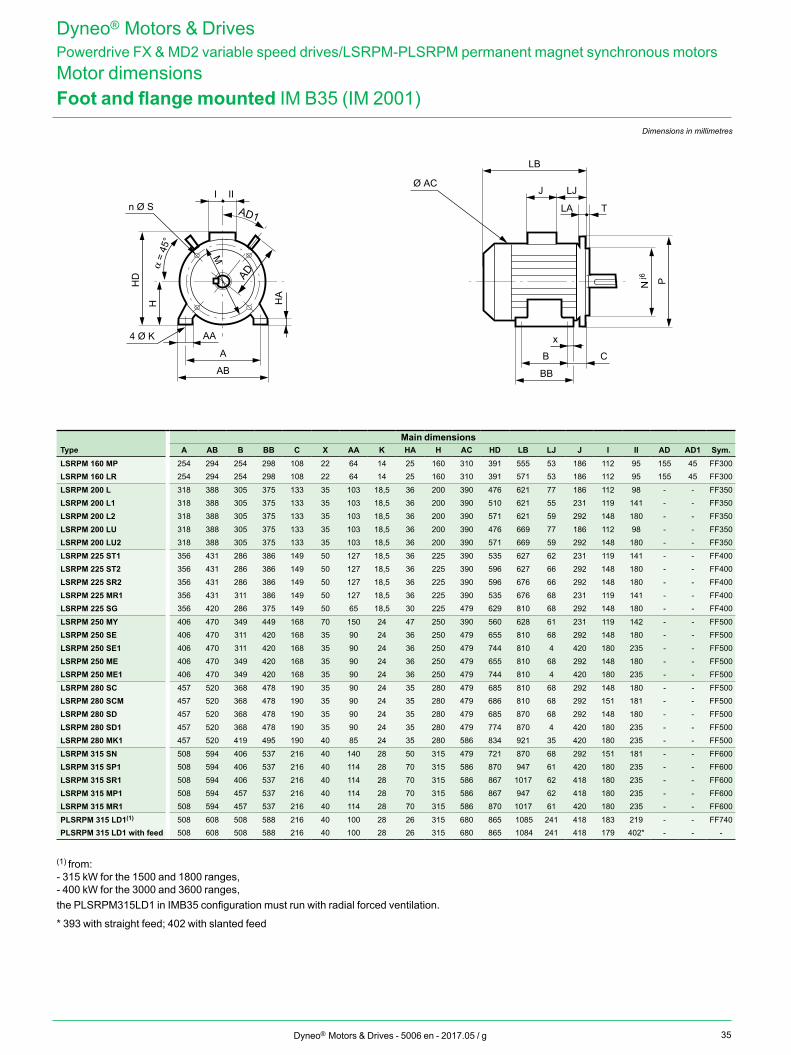
Foot and flange mounted IM B35 (IM 2001)Dimensions in millimetres
Main dimensionsType A AB B BB C X AA K HA H AC HD LB LJ J I II AD AD1 Sym.LSRPM 160 MP 254 294 254 298 108 22 64 14 25 160 310 391 555 53 186 112 95 155 45 FF300LSRPM 160 LR 254 294 254 298 108 22 64 14 25 160 310 391 571 53 186 112 95 155 45 FF300
LSRPM 200 L 318 388 305 375 133 35 103 18,5 36 200 390 476 621 77 186 112 98 - - FF350LSRPM 200 L1 318 388 305 375 133 35 103 18,5 36 200 390 510 621 55 231 119 141 - - FF350LSRPM 200 L2 318 388 305 375 133 35 103 18,5 36 200 390 571 621 59 292 148 180 - - FF350LSRPM 200 LU 318 388 305 375 133 35 103 18,5 36 200 390 476 669 77 186 112 98 - - FF350LSRPM 200 LU2 318 388 305 375 133 35 103 18,5 36 200 390 571 669 59 292 148 180 - - FF350
LSRPM 225 ST1 356 431 286 386 149 50 127 18,5 36 225 390 535 627 62 231 119 141 - - FF400LSRPM 225 ST2 356 431 286 386 149 50 127 18,5 36 225 390 596 627 66 292 148 180 - - FF400LSRPM 225 SR2 356 431 286 386 149 50 127 18,5 36 225 390 596 676 66 292 148 180 - - FF400LSRPM 225 MR1 356 431 311 386 149 50 127 18,5 36 225 390 535 676 68 231 119 141 - - FF400LSRPM 225 SG 356 420 286 375 149 50 65 18,5 30 225 479 629 810 68 292 148 180 - - FF400
LSRPM 250 MY 406 470 349 449 168 70 150 24 47 250 390 560 628 61 231 119 142 - - FF500LSRPM 250 SE 406 470 311 420 168 35 90 24 36 250 479 655 810 68 292 148 180 - - FF500LSRPM 250 SE1 406 470 311 420 168 35 90 24 36 250 479 744 810 4 420 180 235 - - FF500LSRPM 250 ME 406 470 349 420 168 35 90 24 36 250 479 655 810 68 292 148 180 - - FF500LSRPM 250 ME1 406 470 349 420 168 35 90 24 36 250 479 744 810 4 420 180 235 - - FF500
LSRPM 280 SC 457 520 368 478 190 35 90 24 35 280 479 685 810 68 292 148 180 - - FF500LSRPM 280 SCM 457 520 368 478 190 35 90 24 35 280 479 686 810 68 292 151 181 - - FF500LSRPM 280 SD 457 520 368 478 190 35 90 24 35 280 479 685 870 68 292 148 180 - - FF500LSRPM 280 SD1 457 520 368 478 190 35 90 24 35 280 479 774 870 4 420 180 235 - - FF500LSRPM 280 MK1 457 520 419 495 190 40 85 24 35 280 586 834 921 35 420 180 235 - - FF500
LSRPM 315 SN 508 594 406 537 216 40 140 28 50 315 479 721 870 68 292 151 181 - - FF600LSRPM 315 SP1 508 594 406 537 216 40 114 28 70 315 586 870 947 61 420 180 235 - - FF600LSRPM 315 SR1 508 594 406 537 216 40 114 28 70 315 586 867 1017 62 418 180 235 - - FF600LSRPM 315 MP1 508 594 457 537 216 40 114 28 70 315 586 867 947 62 418 180 235 - - FF600LSRPM 315 MR1 508 594 457 537 216 40 114 28 70 315 586 870 1017 61 420 180 235 - - FF600
PLSRPM 315 LD1(1) 508 608 508 588 216 40 100 28 26 315 680 865 1085 241 418 183 219 - - FF740PLSRPM 315 LD1 with feed 508 608 508 588 216 40 100 28 26 315 680 865 1084 241 418 179 402* - - -
(1) from:- 315 kW for the 1500 and 1800 ranges,- 400 kW for the 3000 and 3600 ranges,the PLSRPM315LD1 in IMB35 configuration must run with radial forced ventilation.
* 393 with straight feed; 402 with slanted feed
Dyneo® Motors & DrivesPowerdrive FX & MD2 variable speed drives/LSRPM-PLSRPM permanent magnet synchronous motorsMotor dimensions
A
HD
H
I II
HA
AB
AA
M
n Ø S
4 Ø K
LA
J LJ
LB
T
x
B C
N Pj6
Ø AC
BB
AD
AD1
α =
45°
36 Dyneo® Motors & Drives - 5006 en - 2017.05 / g
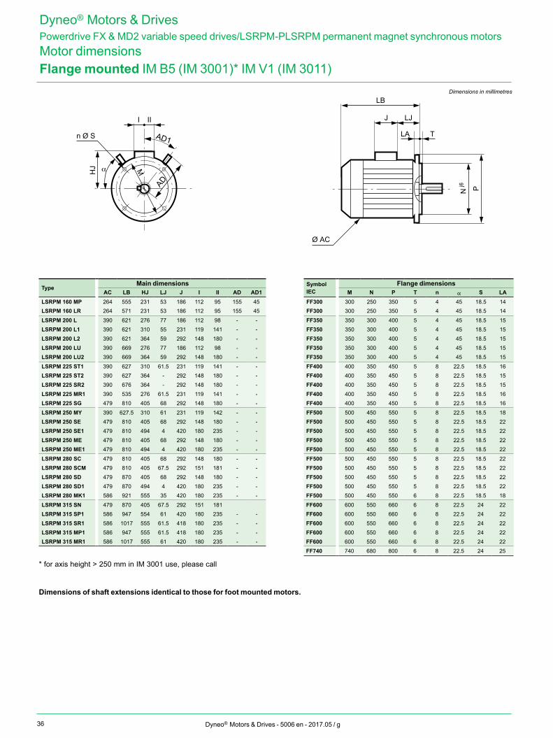
Flange mounted IM B5 (IM 3001)* IM V1 (IM 3011)Dimensions in millimetres
TypeMain dimensions
AC LB HJ LJ J I II AD AD1LSRPM 160 MP 264 555 231 53 186 112 95 155 45LSRPM 160 LR 264 571 231 53 186 112 95 155 45
LSRPM 200 L 390 621 276 77 186 112 98 - -LSRPM 200 L1 390 621 310 55 231 119 141 - -LSRPM 200 L2 390 621 364 59 292 148 180 - -LSRPM 200 LU 390 669 276 77 186 112 98 - -LSRPM 200 LU2 390 669 364 59 292 148 180 - -
LSRPM 225 ST1 390 627 310 61.5 231 119 141 - -LSRPM 225 ST2 390 627 364 - 292 148 180 - -LSRPM 225 SR2 390 676 364 - 292 148 180 - -LSRPM 225 MR1 390 535 276 61.5 231 119 141 - -LSRPM 225 SG 479 810 405 68 292 148 180 - -
LSRPM 250 MY 390 627.5 310 61 231 119 142 - -LSRPM 250 SE 479 810 405 68 292 148 180 - -LSRPM 250 SE1 479 810 494 4 420 180 235 - -LSRPM 250 ME 479 810 405 68 292 148 180 - -LSRPM 250 ME1 479 810 494 4 420 180 235 - -
LSRPM 280 SC 479 810 405 68 292 148 180 - -LSRPM 280 SCM 479 810 405 67.5 292 151 181 - -LSRPM 280 SD 479 870 405 68 292 148 180 - -LSRPM 280 SD1 479 870 494 4 420 180 235 - -LSRPM 280 MK1 586 921 555 35 420 180 235 - -
LSRPM 315 SN 479 870 405 67.5 292 151 181LSRPM 315 SP1 586 947 554 61 420 180 235 - -LSRPM 315 SR1 586 1017 555 61.5 418 180 235 - -LSRPM 315 MP1 586 947 555 61.5 418 180 235 - -LSRPM 315 MR1 586 1017 555 61 420 180 235 - -
* for axis height > 250 mm in IM 3001 use, please call
Dimensions of shaft extensions identical to those for foot mounted motors.
Dyneo® Motors & DrivesPowerdrive FX & MD2 variable speed drives/LSRPM-PLSRPM permanent magnet synchronous motorsMotor dimensions
HJ
I II
n Ø S LA
J LJ
LB
T
N Pj6
Ø AC
α M
AD
AD1
Symbol IEC
Flange dimensionsM N P T n a S LA
FF300 300 250 350 5 4 45 18.5 14FF300 300 250 350 5 4 45 18.5 14
FF350 350 300 400 5 4 45 18.5 15FF350 350 300 400 5 4 45 18.5 15FF350 350 300 400 5 4 45 18.5 15FF350 350 300 400 5 4 45 18.5 15FF350 350 300 400 5 4 45 18.5 15
FF400 400 350 450 5 8 22.5 18.5 16FF400 400 350 450 5 8 22.5 18.5 15FF400 400 350 450 5 8 22.5 18.5 15FF400 400 350 450 5 8 22.5 18.5 16FF400 400 350 450 5 8 22.5 18.5 16
FF500 500 450 550 5 8 22.5 18.5 18FF500 500 450 550 5 8 22.5 18.5 22FF500 500 450 550 5 8 22.5 18.5 22FF500 500 450 550 5 8 22.5 18.5 22FF500 500 450 550 5 8 22.5 18.5 22
FF500 500 450 550 5 8 22.5 18.5 22FF500 500 450 550 5 8 22.5 18.5 22FF500 500 450 550 5 8 22.5 18.5 22FF500 500 450 550 5 8 22.5 18.5 22FF500 500 450 550 6 8 22.5 18.5 18
FF600 600 550 660 6 8 22.5 24 22FF600 600 550 660 6 8 22.5 24 22FF600 600 550 660 6 8 22.5 24 22FF600 600 550 660 6 8 22.5 24 22FF600 600 550 660 6 8 22.5 24 22FF740 740 680 800 6 8 22.5 24 25
37Dyneo® Motors & Drives - 5006 en - 2017.05 / g
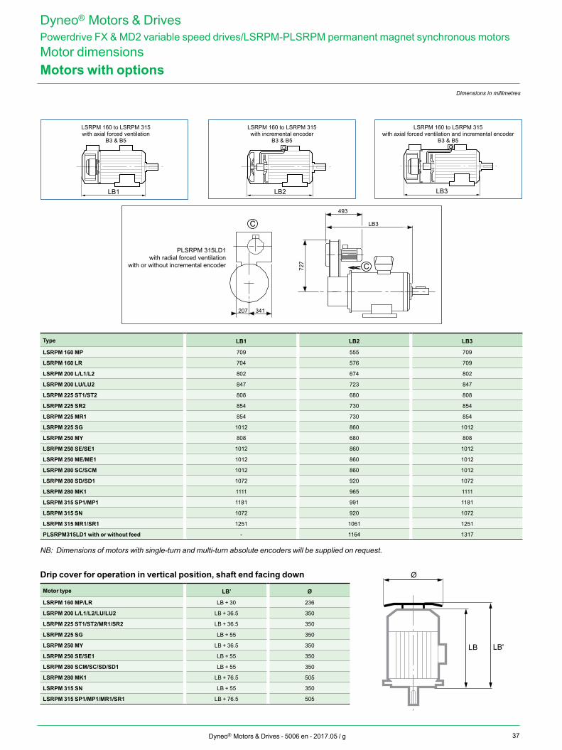
Dimensions in millimetres
Motors with options
LB1 LB2 LB3
Type LB1 LB2 LB3
LSRPM 160 MP 709 555 709
LSRPM 160 LR 704 576 709
LSRPM 200 L/L1/L2 802 674 802
LSRPM 200 LU/LU2 847 723 847
LSRPM 225 ST1/ST2 808 680 808
LSRPM 225 SR2 854 730 854
LSRPM 225 MR1 854 730 854
LSRPM 225 SG 1012 860 1012
LSRPM 250 MY 808 680 808
LSRPM 250 SE/SE1 1012 860 1012
LSRPM 250 ME/ME1 1012 860 1012
LSRPM 280 SC/SCM 1012 860 1012
LSRPM 280 SD/SD1 1072 920 1072
LSRPM 280 MK1 1111 965 1111
LSRPM 315 SP1/MP1 1181 991 1181
LSRPM 315 SN 1072 920 1072
LSRPM 315 MR1/SR1 1251 1061 1251
PLSRPM315LD1 with or without feed - 1164 1317
NB: Dimensions of motors with single-turn and multi-turn absolute encoders will be supplied on request.
Drip cover for operation in vertical position, shaft end facing down
Motor type LB’ Ø
LSRPM 160 MP/LR LB + 30 236
LSRPM 200 L/L1/L2/LU/LU2 LB + 36.5 350
LSRPM 225 ST1/ST2/MR1/SR2 LB + 36.5 350
LSRPM 225 SG LB + 55 350
LSRPM 250 MY LB + 36.5 350
LSRPM 250 SE/SE1 LB + 55 350
LSRPM 280 SCM/SC/SD/SD1 LB + 55 350
LSRPM 280 MK1 LB + 76.5 505
LSRPM 315 SN LB + 55 350
LSRPM 315 SP1/MP1/MR1/SR1 LB + 76.5 505
LSRPM 160 to LSRPM 315 with axial forced ventilation
B3 & B5
LSRPM 160 to LSRPM 315 with incremental encoder
B3 & B5
LSRPM 160 to LSRPM 315 with axial forced ventilation and incremental encoder
B3 & B5
Dyneo® Motors & DrivesPowerdrive FX & MD2 variable speed drives/LSRPM-PLSRPM permanent magnet synchronous motorsMotor dimensions
LB LB'
Ø
C
C
207 341
493
LB3
727
PLSRPM 315LD1with radial forced ventilation
with or without incremental encoder
38 Dyneo® Motors & Drives - 5006 en - 2017.05 / g
Dyneo® Motors & DrivesPowerdrive FX & MD2 variable speed drives/LSRPM-PLSRPM permanent magnet synchronous motorsInstallation and optionsGeneral
Influence of the AC supplyEach industrial power supply has its own intrinsic characteristics (short-circuit capability, voltage value and fluctuation, phase imbalance, etc.) and supplies equipment some of which can distort its voltage either permanently or temporarily (notches, voltage dips, overvoltage, etc.). The quality of the AC supply has an impact on the performance and reliability of electronic equipment, especially variable speed drives.Nidec drives are designed to operate with the AC supplies typically found on industrial sites throughout the world.However, for each installation, it is important to know the characteristics of the AC supply so that you can take corrective steps in the event of abnormal conditions.
Transient overvoltagesThere are numerous sources of overvoltages on an electrical installation:• Connection/disconnection of banks of
power factor correction capacitors• High-power thyristor-controlled
equipment (oven, DC drive, etc.)• Overhead power supply
Connection/disconnection of a bank of correction capacitors cos jConnecting power factor correction capacitors in parallel on the drive power supply line when the drive is running can generate transient overvoltages that are likely to trip the drive safety devices, or even damage it in extreme cases.If banks of power factor correction capacitors are used on the power supply line, make sure that:• The threshold between steps is low enough to avoid causing overvoltage on the line
• The capacitors are not permanently connected
Presence of commutation notches on the lineWhen high-power thyristor-controlled equipment is connected on the same line as the drive, it is essential to ensure that the harmonics generated by the commutation notches do not excessively distort the AC voltage and do not create voltage peaks with amplitude higher than 1.6 x line Vrms. If this is the case, it is essential to take corrective measures to guarantee the line supply quality.
Unbalanced power supply In the same way as can be seen on an electric motor, the line voltage imbalance of a drive can have consequences on its operation. Please refer to the drive installation manual. Equipotential bondingThe equipotential earth bonding of some industrial sites is sometimes neglected. This lack of equipotentiality leads to leakage currents which flow via the earth cables (green/yellow), the machine chassis, the pipework, etc., and also via the electrical equipment. In some extreme cases, these currents can trip the drive.It is essential that the earth network is designed and implemented by the installation supervisor so that its impedance is as low as possible, so as to distribute the fault currents and high-frequency currents without them passing through electrical equipment.Metal grounds must be mechanically connected to each other with the largest possible electrical contact area. Under no circumstances can earth connections designed to protect people, by linking metal grounds to earth via a cable, serve as a substitute for ground connections (see IEC 61000-5-2).
The immunity and radio-frequency emission level are directly linked to the quality of the ground connections.
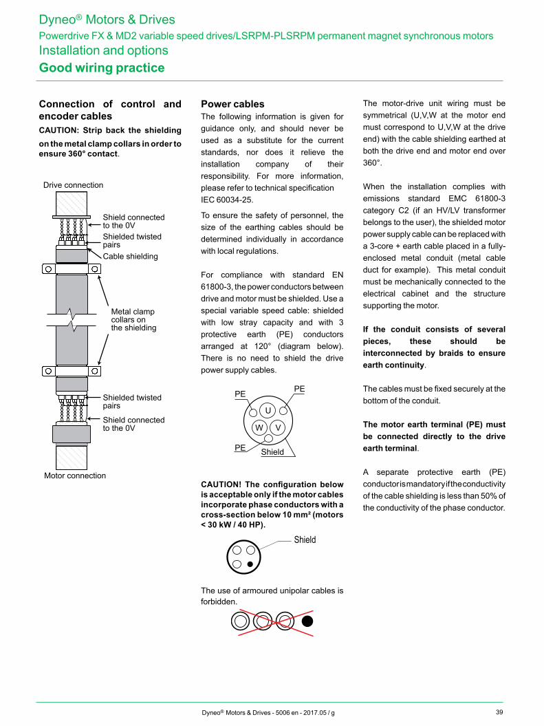
39Dyneo® Motors & Drives - 5006 en - 2017.05 / g
Metal clamp collars on the shielding
Shield connected to the 0V
Shield connected to the 0V
Shielded twisted pairs
Shielded twisted pairs
Cable shielding
Drive connection
Motor connection
Dyneo® Motors & DrivesPowerdrive FX & MD2 variable speed drives/LSRPM-PLSRPM permanent magnet synchronous motorsInstallation and optionsGood wiring practice
Connection of control and encoder cablesCAUTION: Strip back the shielding on the metal clamp collars in order to ensure 360° contact.
Power cablesThe following information is given for guidance only, and should never be used as a substitute for the current standards, nor does it relieve the installation company of their responsibility. For more information, please refer to technical specificationIEC 60034-25.
To ensure the safety of personnel, the size of the earthing cables should be determined individually in accordance with local regulations.
For compliance with standard EN 61800-3, the power conductors between drive and motor must be shielded. Use a special variable speed cable: shielded with low stray capacity and with 3 protective earth (PE) conductors arranged at 120° (diagram below). There is no need to shield the drive power supply cables.
U
V
Shield
PEPE
PE
W
CAUTION! The configuration below is acceptable only if the motor cables incorporate phase conductors with a cross-section below 10 mm² (motors < 30 kW / 40 HP).
Shield
The use of armoured unipolar cables is forbidden.
The motor-drive unit wiring must be symmetrical (U,V,W at the motor end must correspond to U,V,W at the drive end) with the cable shielding earthed at both the drive end and motor end over 360°.
When the installation complies with emissions standard EMC 61800-3 category C2 (if an HV/LV transformer belongs to the user), the shielded motor power supply cable can be replaced with a 3-core + earth cable placed in a fully-enclosed metal conduit (metal cable duct for example). This metal conduit must be mechanically connected to the electrical cabinet and the structure supporting the motor.
If the conduit consists of several pieces, these should be interconnected by braids to ensure earth continuity.
The cables must be fixed securely at the bottom of the conduit.
The motor earth terminal (PE) must be connected directly to the drive earth terminal.
A separate protective earth (PE) conductor is mandatory if the conductivity of the cable shielding is less than 50% of the conductivity of the phase conductor.
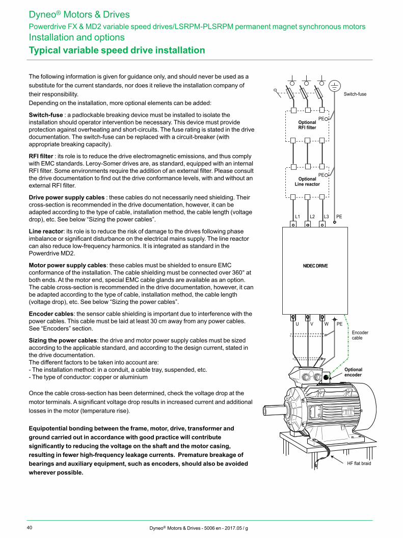
40 Dyneo® Motors & Drives - 5006 en - 2017.05 / g
Dyneo® Motors & DrivesPowerdrive FX & MD2 variable speed drives/LSRPM-PLSRPM permanent magnet synchronous motorsInstallation and optionsTypical variable speed drive installation
The following information is given for guidance only, and should never be used as a substitute for the current standards, nor does it relieve the installation company of their responsibility.Depending on the installation, more optional elements can be added:
Switch-fuse : a padlockable breaking device must be installed to isolate the installation should operator intervention be necessary. This device must provide protection against overheating and short-circuits. The fuse rating is stated in the drive documentation. The switch-fuse can be replaced with a circuit-breaker (with appropriate breaking capacity).
RFI filter : its role is to reduce the drive electromagnetic emissions, and thus comply with EMC standards. Leroy-Somer drives are, as standard, equipped with an internal RFI filter. Some environments require the addition of an external filter. Please consult the drive documentation to find out the drive conformance levels, with and without an external RFI filter.
Drive power supply cables : these cables do not necessarily need shielding. Their cross-section is recommended in the drive documentation, however, it can be adapted according to the type of cable, installation method, the cable length (voltage drop), etc. See below “Sizing the power cables”.
Line reactor: its role is to reduce the risk of damage to the drives following phase imbalance or significant disturbance on the electrical mains supply. The line reactor can also reduce low-frequency harmonics. It is integrated as standard in the Powerdrive MD2.
Motor power supply cables: these cables must be shielded to ensure EMC conformance of the installation. The cable shielding must be connected over 360° at both ends. At the motor end, special EMC cable glands are available as an option. The cable cross-section is recommended in the drive documentation, however, it can be adapted according to the type of cable, installation method, the cable length (voltage drop), etc. See below “Sizing the power cables”.
Encoder cables: the sensor cable shielding is important due to interference with the power cables. This cable must be laid at least 30 cm away from any power cables. See “Encoders” section.
Sizing the power cables: the drive and motor power supply cables must be sized according to the applicable standard, and according to the design current, stated in the drive documentation.The different factors to be taken into account are:- The installation method: in a conduit, a cable tray, suspended, etc.- The type of conductor: copper or aluminium
Once the cable cross-section has been determined, check the voltage drop at the motor terminals. A significant voltage drop results in increased current and additional losses in the motor (temperature rise).
Equipotential bonding between the frame, motor, drive, transformer and ground carried out in accordance with good practice will contribute significantly to reducing the voltage on the shaft and the motor casing, resulting in fewer high-frequency leakage currents. Premature breakage of bearings and auxiliary equipment, such as encoders, should also be avoided wherever possible.
L1 L2 L3 PE
U V W PE
PE
PE
NIDEC DRIVE
OptionalRFI filter
AC supply
Switch-fuse
OptionalLine reactor
Optional encoder
Encoder cable
HF flat braid
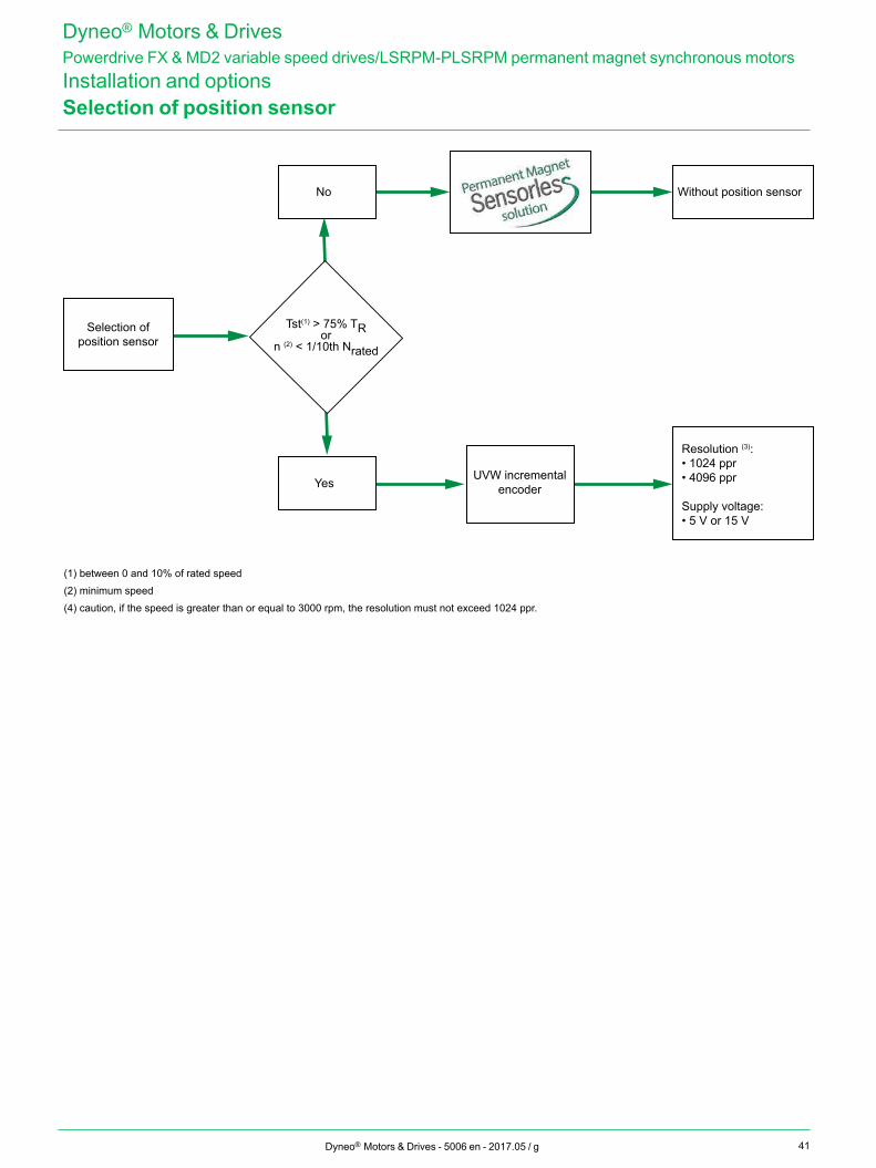
41Dyneo® Motors & Drives - 5006 en - 2017.05 / g
Selection of position sensor
(1) between 0 and 10% of rated speed(2) minimum speed(4) caution, if the speed is greater than or equal to 3000 rpm, the resolution must not exceed 1024 ppr.
Selection ofposition sensor
Tst(1) > 75% TRorn (2) < 1/10th Nrated
No
YesUVW incremental
encoder
Resolution (3): • 1024 ppr• 4096 ppr
Supply voltage: • 5 V or 15 V
Without position sensor
Dyneo® Motors & DrivesPowerdrive FX & MD2 variable speed drives/LSRPM-PLSRPM permanent magnet synchronous motorsInstallation and options
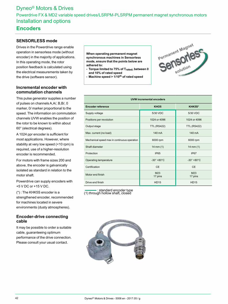
42
Permanent Magnet
solution
Dyneo® Motors & Drives - 5006 en - 2017.05 / g
SENSORLESS modeDrives in the Powerdrive range enable operation in sensorless mode (without encoder) in the majority of applications. In this operating mode, the rotor position feedback is calculated using the electrical measurements taken by the drive (software sensor).
Incremental encoder with commutation channelsThis pulse generator supplies a number of pulses on channels A,A/, B,B/, 0 marker, 0/ marker proportional to the speed. The information on commutation channels UVW enables the position of the rotor to be known to within about 60° (electrical degrees).
A 1024 ppr encoder is sufficient for most applications. However, where stability at very low speed (<10 rpm) is required, use of a higher-resolution encoder is recommended.
For motors with frame sizes 200 and above, the encoder is galvanically isolated as standard in relation to the motor shaft.
Powerdrive can supply encoders with +5 V DC or +15 V DC.
(*) : The KHK5S encoder is a strengthened encoder, recommended for machines located in severe environments (dusty atmospheres).
Encoder-drive connecting cableIt may be possible to order a suitable cable, guaranteeing optimum performance of the drive connection. Please consult your usual contact.
UVW incremental encoders
Encoder reference KHO5 KHK5S*
Supply voltage 5/30 VDC 5/30 VDC
Positions per revolution 1024 or 4096 1024 or 4096
Output stage TTL (RS422) TTL (RS422)
Max. current (no load) 140 mA 140 mA
Mechanical speed max in continuous operation 6000 rpm 6000 rpm
Shaft diameter 14 mm (1) 14 mm (1)
Protection IP65 IP67
Operating temperature -30° +80°C -30° +80°C
Certification CE CE
Motor end finish M23 17 pins
M23 17 pins
Drive end finish HD15 HD15
(1) through hollow shaft, closed
Encoders
Dyneo® Motors & DrivesPowerdrive FX & MD2 variable speed drives/LSRPM-PLSRPM permanent magnet synchronous motorsInstallation and options
When operating permanent magnet synchronous machines in Sensorless mode, ensure that the points below are adhered to:- Torque limited to 75% of Trated, between 0
and 10% of rated speed- Machine speed > 1/10th of rated speed
: standard encoder type
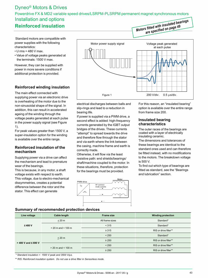
43Dyneo® Motors & Drives - 5006 en - 2017.05 / g
Reinforced insulation
200 V/divFigure 1 . 0.5 µs/div.
Voltage peak generated at each pulse
Motor power supply signal
Motors fitted with insulated bearings
are specified on page 49
Dyneo® Motors & DrivesPowerdrive FX & MD2 variable speed drives/LSRPM-PLSRPM permanent magnet synchronous motorsInstallation and options
Reinforced winding insulationThe main effect connected with supplying power via an electronic drive is overheating of the motor due to the non-sinusoidal shape of the signal. In addition, this can result in accelerated ageing of the winding through the voltage peaks generated at each pulse in the power supply signal (see Figure 1).For peak values greater than 1500 V, a super-insulation option for the winding is available over the entire range.
Reinforced insulation of the mechanismSupplying power via a drive can affect the mechanism and lead to premature wear of the bearings.This is because, in any motor, a shaft voltage exists with respect to earth. This voltage, due to electro-mechanical dissymmetries, creates a potential difference between the rotor and the stator. This effect can generate
electrical discharges between balls and slip-rings and lead to a reduction in bearing life.If power is supplied via a PWM drive, a second effect is added: high-frequency currents generated by the IGBT output bridges of the drives. These currents “attempt” to spread towards the drive and therefore flow through the stator and via earth where the link between the casing, machine frame and earth is correctly made. Otherwise, it will flow via the least resistive path: end shields/bearings/shaft/machine coupled to the motor. In these situations, therefore, protection for the bearings must be provided.
For this reason, an “insulated bearing” option is available over the entire range from frame size 200.
Insulated bearing characteristicsThe outer races of the bearings are coated with a layer of electrically insulating ceramic.The dimensions and tolerances of these bearings are identical to the standard ones used and can therefore be fitted instead, with no modifications to the motors. The breakdown voltage is 500 V.To find out which type of bearings are fitted as standard, see the “Bearings and lubrication” section.
Line voltage Cable length Frame size Winding protection
≤ 480 V
< 20 m All frame sizes Standard*
> 20 m and < 100 m< 315 Standard*
≥ 315 RIS or drive filter**
> 480 V and ≤ 690 V
< 20 m< 250 Standard*
≥ 250 RIS or drive filter**
> 20 m and < 100 m< 250 RIS or drive filter**
≥ 250 RIS or drive filter**
* Standard insulation = 1500 V peak and 3500 V/µs.
** RIS: Reinforced insulation system. Do not use a drive filter in Sensorless mode.
Standard motors are compatible with power supplies with the following characteristics:• U rms = 480 V max.• Value of voltage peaks generated at
the terminals: 1500 V max.
However, they can be supplied with power in more severe conditions if additional protection is provided.
HF common mode currents
MotorPWM drive
Summary of recommended protection devices
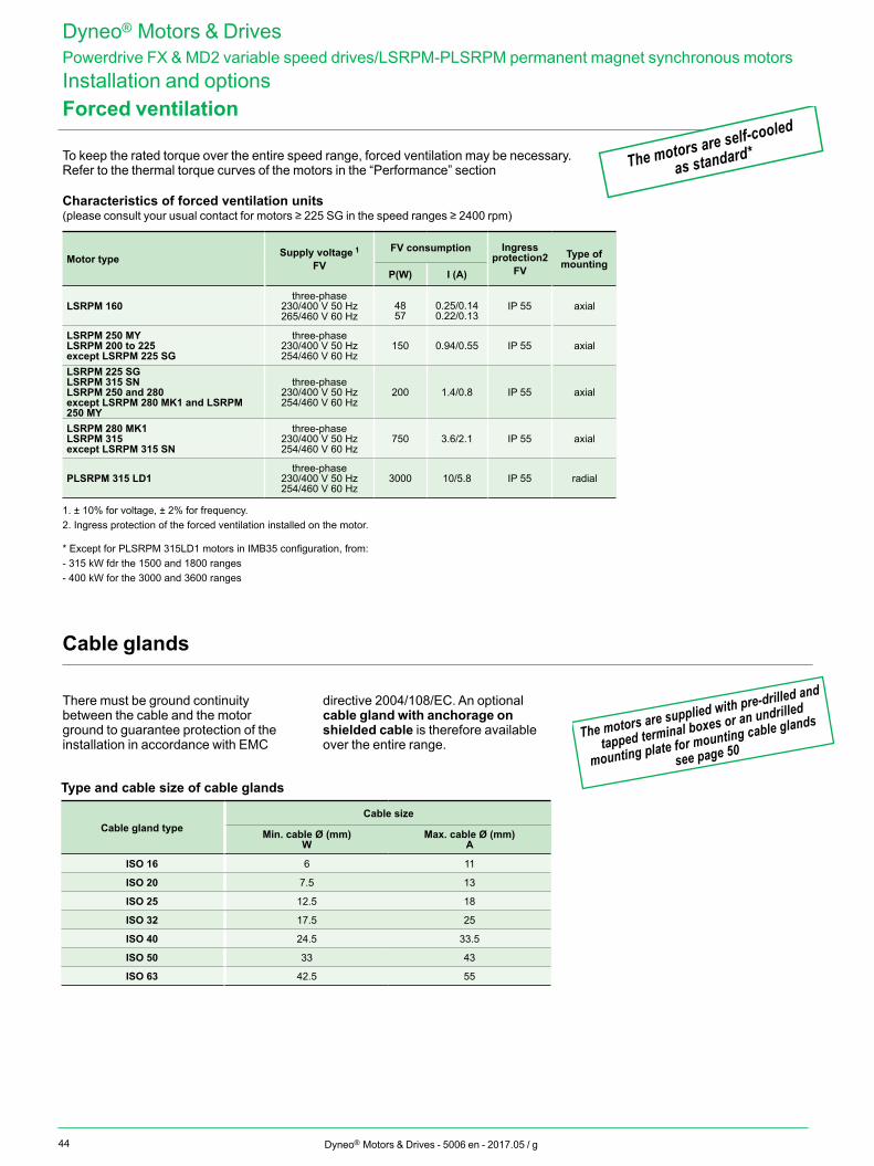
44 Dyneo® Motors & Drives - 5006 en - 2017.05 / g
Forced ventilation
The motors are self-cooled
as standard*
Dyneo® Motors & DrivesPowerdrive FX & MD2 variable speed drives/LSRPM-PLSRPM permanent magnet synchronous motorsInstallation and options
To keep the rated torque over the entire speed range, forced ventilation may be necessary. Refer to the thermal torque curves of the motors in the “Performance” section
Characteristics of forced ventilation units(please consult your usual contact for motors ≥ 225 SG in the speed ranges ≥ 2400 rpm)
Motor type Supply voltage 1
FV
FV consumption Ingress protection2
FVType of
mountingP(W) I (A)
LSRPM 160three-phase
230/400 V 50 Hz 265/460 V 60 Hz
4857
0.25/0.140.22/0.13
IP 55 axial
LSRPM 250 MYLSRPM 200 to 225except LSRPM 225 SG
three-phase 230/400 V 50 Hz 254/460 V 60 Hz
150 0.94/0.55 IP 55 axial
LSRPM 225 SGLSRPM 315 SNLSRPM 250 and 280except LSRPM 280 MK1 and LSRPM 250 MY
three-phase 230/400 V 50 Hz 254/460 V 60 Hz
200 1.4/0.8 IP 55 axial
LSRPM 280 MK1LSRPM 315except LSRPM 315 SN
three-phase 230/400 V 50 Hz 254/460 V 60 Hz
750 3.6/2.1 IP 55 axial
PLSRPM 315 LD1three-phase
230/400 V 50 Hz 254/460 V 60 Hz
3000 10/5.8 IP 55 radial
1. ± 10% for voltage, ± 2% for frequency.2. Ingress protection of the forced ventilation installed on the motor.
* Except for PLSRPM 315LD1 motors in IMB35 configuration, from:- 315 kW fdr the 1500 and 1800 ranges- 400 kW for the 3000 and 3600 ranges
Cable glands
There must be ground continuity between the cable and the motor ground to guarantee protection of the installation in accordance with EMC
directive 2004/108/EC. An optional cable gland with anchorage on shielded cable is therefore available over the entire range.
Type and cable size of cable glands
Cable gland typeCable size
Min. cable Ø (mm) W
Max. cable Ø (mm) A
ISO 16 6 11
ISO 20 7.5 13
ISO 25 12.5 18
ISO 32 17.5 25
ISO 40 24.5 33.5
ISO 50 33 43
ISO 63 42.5 55
The motors are supplied with pre-drilled and
tapped terminal boxes or an undrilled
mounting plate for mounting cable glands
see page 50
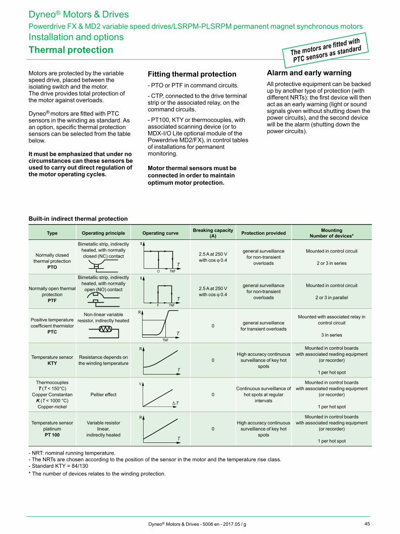
45Dyneo® Motors & Drives - 5006 en - 2017.05 / g
Thermal protection
Motors are protected by the variable speed drive, placed between the isolating switch and the motor.The drive provides total protection of the motor against overloads.
Dyneo® motors are fitted with PTC sensors in the winding as standard. As an option, specific thermal protection sensors can be selected from the table below.
It must be emphasized that under no circumstances can these sensors be used to carry out direct regulation of the motor operating cycles.
Fitting thermal protection- PTO or PTF in command circuits.
- CTP, connected to the drive terminal strip or the associated relay, on the command circuits.
- PT100, KTY or thermocouples, with associated scanning device (or to MDX-I/O Lite optional module of the Powerdrive MD2/FX), in control tables of installations for permanent monitoring.
Motor thermal sensors must be connected in order to maintain optimum motor protection.
Alarm and early warningAll protective equipment can be backed up by another type of protection (with different NRTs): the first device will then act as an early warning (light or sound signals given without shutting down the power circuits), and the second device will be the alarm (shutting down the power circuits).
Built-in indirect thermal protection
Type Operating principle Operating curve Breaking capacity (A) Protection provided Mounting
Number of devices*
Normally closed thermal protection
PTO
Bimetallic strip, indirectly heated, with normally closed (NC) contact
I
O TNFT
2.5 A at 250 Vwith cos j 0.4
general surveillance for non-transient
overloads
Mounted in control circuit
2 or 3 in series
Normally open thermal protection
PTF
Bimetallic strip, indirectly heated, with normally
open (NO) contact
I
F TNFT
2.5 A at 250 Vwith cos j 0.4
general surveillance for non-transient
overloads
Mounted in control circuit
2 or 3 in parallel
Positive temperature coefficient thermistor
PTC
Non-linear variable resistor, indirectly heated
R
TNFT
0 general surveillance for transient overloads
Mounted with associated relay in control circuit
3 in series
Temperature sensorKTY
Resistance depends on the winding temperature
R
T
0High accuracy continuous
surveillance of key hot spots
Mounted in control boards with associated reading equipment
(or recorder)
1 per hot spot
ThermocouplesT (T < 150°C)
Copper Constantan K (T < 1000 °C)Copper-nickel
Peltier effect
V
T
0Continuous surveillance of
hot spots at regular intervals
Mounted in control boards with associated reading equipment
(or recorder)
1 per hot spot
Temperature sensorplatinumPT 100
Variable resistorlinear,
indirectly heated
R
T
0High accuracy continuous
surveillance of key hot spots
Mounted in control boards with associated reading equipment
(or recorder)
1 per hot spot
- NRT: nominal running temperature.- The NRTs are chosen according to the position of the sensor in the motor and the temperature rise class.- Standard KTY = 84/130* The number of devices relates to the winding protection.
The motors are fitted with
PTC sensors as standard
Dyneo® Motors & DrivesPowerdrive FX & MD2 variable speed drives/LSRPM-PLSRPM permanent magnet synchronous motorsInstallation and options
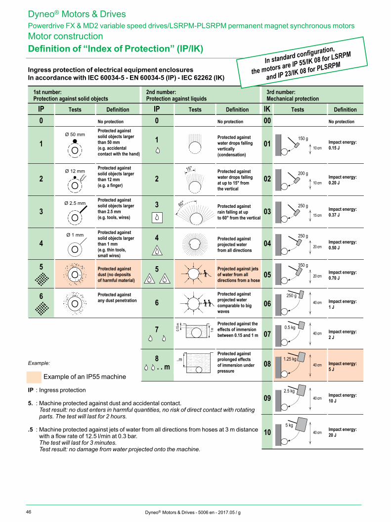
46 Dyneo® Motors & Drives - 5006 en - 2017.05 / g
Definition of “Index of Protection” (IP/IK)
Ingress protection of electrical equipment enclosuresIn accordance with IEC 60034-5 - EN 60034-5 (IP) - IEC 62262 (IK)
IP0
1
2
3
4
5
Tests Definition IP Tests Definition IK Tests Definition
1st number:Protection against solid objects
3rd number:Mechanical protection
Ø 50 mm
Ø 12 mm
No protection
Protected against solid objects larger than 12 mm(e.g. a finger)
Protected against solid objects larger than 50 mm(e.g. accidental contact with the hand)
Protected against solid objects larger than 2.5 mm(e.g. tools, wires)
Ø 2.5 mm
Protected against solid objects larger than 1 mm(e.g. thin tools, small wires)
Ø 1 mm
2nd number:Protection against liquids
0 No protection 00 No protection
1
15°
2
3
4
60°
5
6
7
8 ..m
0.15 m
1 m
Protected against dust (no deposits of harmful material)
Protected against any dust penetration
Protected against prolonged effects of immersion under pressure
Protected against the effects of immersion between 0.15 and 1 m
Protected against projected water comparable to big waves
Projected against jets of water from all directions from a hose
Protected against projected water from all directions
Protected against rain falling at up to 60° from the vertical
Protected against water drops falling at up to 15° from the vertical
Protected against water drops falling vertically(condensation)
01 Impact energy:0.15 J
02 Impact energy:0.20 J
03 Impact energy:0.37 J
05 Impact energy:0.70 J
07 Impact energy:2 J
09 Impact energy:10 J
150 g
10 cm
250 g
15 cm
250 g
20 cm
250 g40 cm
0.5 kg40 cm
2.5 kg40 cm
. . m
6
200 g
10 cm
350 g
20 cm
04
06
081.25 kg
40 cm
10 Impact energy:20 J
5 kg40 cm
Impact energy:5 J
Impact energy:1 J
Impact energy:0.50 J
Example:
Example of an IP55 machine
IP : Ingress protection
5. : Machine protected against dust and accidental contact. Test result: no dust enters in harmful quantities, no risk of direct contact with rotating
parts. The test will last for 2 hours. .5 : Machine protected against jets of water from all directions from hoses at 3 m distance
with a flow rate of 12.5 l/min at 0.3 bar. The test will last for 3 minutes. Test result: no damage from water projected onto the machine.
In standard configuration,
the motors are IP 55/IK 08 for LSRPM
and IP 23/IK 08 for PLSRPM
Dyneo® Motors & DrivesPowerdrive FX & MD2 variable speed drives/LSRPM-PLSRPM permanent magnet synchronous motorsMotor construction
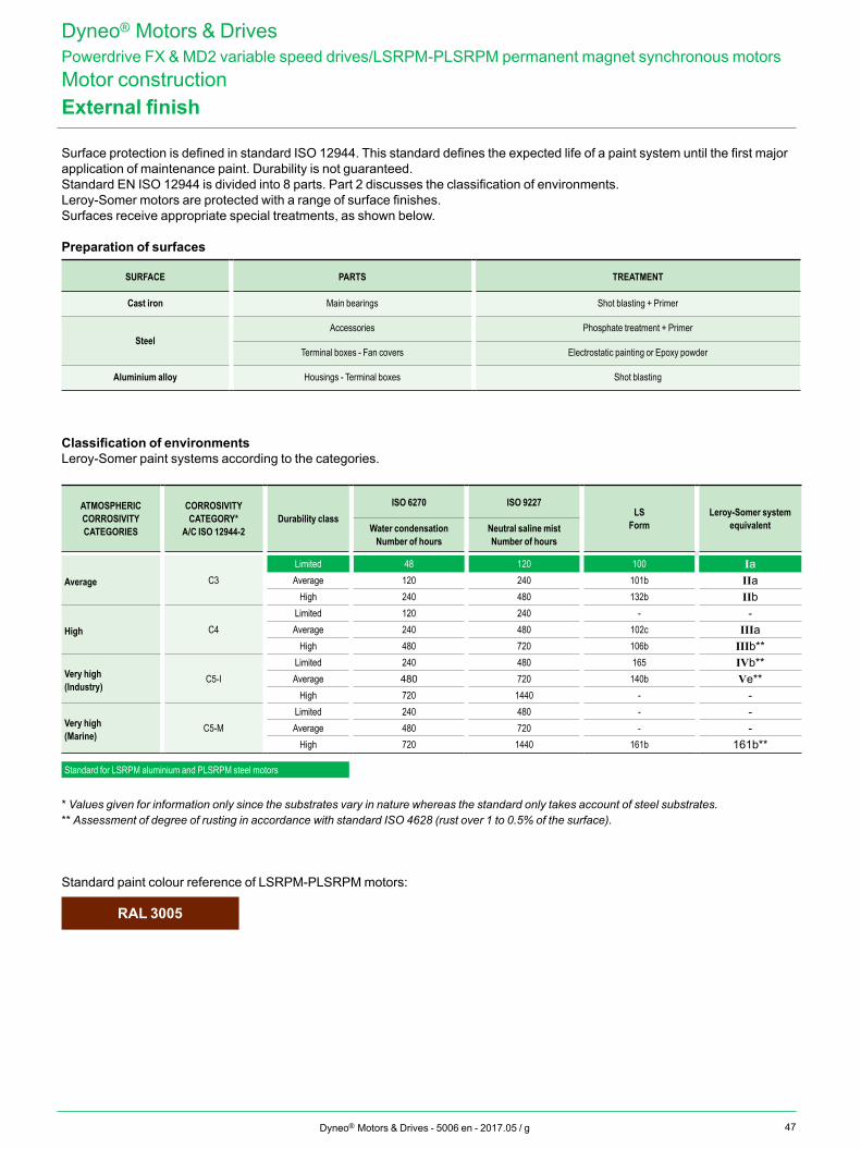
47Dyneo® Motors & Drives - 5006 en - 2017.05 / g
External finish
Surface protection is defined in standard ISO 12944. This standard defines the expected life of a paint system until the first major application of maintenance paint. Durability is not guaranteed.Standard EN ISO 12944 is divided into 8 parts. Part 2 discusses the classification of environments.Leroy-Somer motors are protected with a range of surface finishes.Surfaces receive appropriate special treatments, as shown below.
Preparation of surfaces
SURFACE PARTS TREATMENT
Cast iron Main bearings Shot blasting + Primer
SteelAccessories Phosphate treatment + Primer
Terminal boxes - Fan covers Electrostatic painting or Epoxy powder
Aluminium alloy Housings - Terminal boxes Shot blasting
Classification of environmentsLeroy-Somer paint systems according to the categories.
ATMOSPHERIC CORROSIVITY CATEGORIES
CORROSIVITY CATEGORY*
A/C ISO 12944-2Durability class
ISO 6270 ISO 9227LS
FormLeroy-Somer system
equivalentWater condensationNumber of hours
Neutral saline mistNumber of hours
Average C3Limited 48 120 100 IaAverage 120 240 101b IIa
High 240 480 132b IIb
High C4Limited 120 240 - -Average 240 480 102c IIIa
High 480 720 106b IIIb**
Very high(Industry)
C5-ILimited 240 480 165 IVb**Average 480 720 140b Ve**
High 720 1440 - -
Very high(Marine)
C5-MLimited 240 480 - -Average 480 720 - -
High 720 1440 161b 161b**
Standard for LSRPM aluminium and PLSRPM steel motors
* Values given for information only since the substrates vary in nature whereas the standard only takes account of steel substrates.** Assessment of degree of rusting in accordance with standard ISO 4628 (rust over 1 to 0.5% of the surface).
Standard paint colour reference of LSRPM-PLSRPM motors:
RAL 3005
Dyneo® Motors & DrivesPowerdrive FX & MD2 variable speed drives/LSRPM-PLSRPM permanent magnet synchronous motorsMotor construction
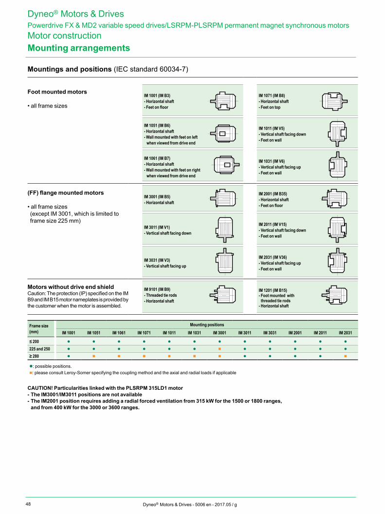
48 Dyneo® Motors & Drives - 5006 en - 2017.05 / g
Mounting arrangements
Mountings and positions (IEC standard 60034-7)
Foot mounted motors
• all frame sizes
IM 1001 (IM B3)- Horizontal shaft- Feet on floor
IM 1071 (IM B8)- Horizontal shaft- Feet on top
IM 1051 (IM B6)- Horizontal shaft- Wall mounted with feet on left when viewed from drive end
IM 1011 (IM V5)- Vertical shaft facing down- Feet on wall
IM 1061 (IM B7)- Horizontal shaft- Wall mounted with feet on right when viewed from drive end
IM 1031 (IM V6)- Vertical shaft facing up- Feet on wall
(FF) flange mounted motors
• all frame sizes (except IM 3001, which is limited to frame size 225 mm)
IM 3001 (IM B5)- Horizontal shaft
IM 2001 (IM B35)- Horizontal shaft- Feet on floor
IM 3011 (IM V1)- Vertical shaft facing down
IM 2011 (IM V15)- Vertical shaft facing down- Feet on wall
IM 3031 (IM V3)- Vertical shaft facing up
IM 2031 (IM V36)- Vertical shaft facing up- Feet on wall
Motors without drive end shieldCaution: The protection (IP) specified on the IM B9 and IM B15 motor nameplates is provided by the customer when the motor is assembled.
IM 9101 (IM B9)- Threaded tie rods- Horizontal shaft
IM 1201 (IM B15)- Foot mounted with threaded tie rods
- Horizontal shaft
Frame size (mm)
Mounting positions
IM 1001 IM 1051 IM 1061 IM 1071 IM 1011 IM 1031 IM 3001 IM 3011 IM 3031 IM 2001 IM 2011 IM 2031
≤ 200 l l l l l l l l l l l l
225 and 250 l l l l l l n l l l l l
≥ 280 l n n n n n n l l l l n
l: possible positions.n: please consult Leroy-Somer specifying the coupling method and the axial and radial loads if applicable
CAUTION! Particularities linked with the PLSRPM 315LD1 motor- The IM3001/IM3011 positions are not available- The IM2001 position requires adding a radial forced ventilation from 315 kW for the 1500 or 1800 ranges,
and from 400 kW for the 3000 or 3600 ranges.
Dyneo® Motors & DrivesPowerdrive FX & MD2 variable speed drives/LSRPM-PLSRPM permanent magnet synchronous motorsMotor construction
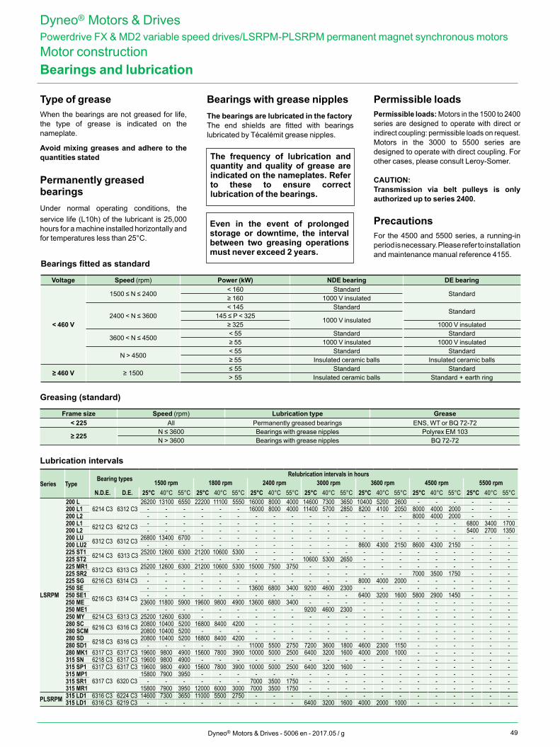
49Dyneo® Motors & Drives - 5006 en - 2017.05 / g
Type of grease When the bearings are not greased for life, the type of grease is indicated on the nameplate.
Avoid mixing greases and adhere to the quantities stated
Permanently greased bearings Under normal operating conditions, the service life (L10h) of the lubricant is 25,000 hours for a machine installed horizontally and for temperatures less than 25°C.
Bearings with grease nipples The bearings are lubricated in the factory The end shields are fitted with bearings lubricated by Técalémit grease nipples.
Permissible loadsPermissible loads: Motors in the 1500 to 2400 series are designed to operate with direct or indirect coupling: permissible loads on request.Motors in the 3000 to 5500 series are designed to operate with direct coupling. For other cases, please consult Leroy-Somer.
CAUTION:Transmission via belt pulleys is only authorized up to series 2400.
PrecautionsFor the 4500 and 5500 series, a running-in period is necessary. Please refer to installation and maintenance manual reference 4155.
The frequency of lubrication and quantity and quality of grease are indicated on the nameplates. Refer to these to ensure correct lubrication of the bearings.
Even in the event of prolonged storage or downtime, the interval between two greasing operations must never exceed 2 years.
Bearings and lubrication
Dyneo® Motors & DrivesPowerdrive FX & MD2 variable speed drives/LSRPM-PLSRPM permanent magnet synchronous motorsMotor construction
Bearings fitted as standard
Voltage Speed (rpm) Power (kW) NDE bearing DE bearing
< 460 V
1500 ≤ N ≤ 2400< 160 Standard
Standard≥ 160 1000 V insulated
2400 < N ≤ 3600< 145 Standard
Standard145 ≤ P < 325
1000 V insulated≥ 325 1000 V insulated
3600 < N ≤ 4500< 55 Standard Standard≥ 55 1000 V insulated 1000 V insulated
N > 4500< 55 Standard Standard≥ 55 Insulated ceramic balls Insulated ceramic balls
≥ 460 V ≥ 1500≤ 55 Standard Standard> 55 Insulated ceramic balls Standard + earth ring
Greasing (standard)
Frame size Speed (rpm) Lubrication type Grease< 225 All Permanently greased bearings ENS, WT or BQ 72-72
≥ 225 N ≤ 3600 Bearings with grease nipples Polyrex EM 103N > 3600 Bearings with grease nipples BQ 72-72
Lubrication intervals
Series TypeBearing types Relubrication intervals in hours
1500 rpm 1800 rpm 2400 rpm 3000 rpm 3600 rpm 4500 rpm 5500 rpmN.D.E. D.E. 25°C 40°C 55°C 25°C 40°C 55°C 25°C 40°C 55°C 25°C 40°C 55°C 25°C 40°C 55°C 25°C 40°C 55°C 25°C 40°C 55°C
LSRPM
200 L6214 C3 6312 C3
26200 13100 6550 22200 11100 5550 16000 8000 4000 14600 7300 3650 10400 5200 2600 - - - - - -200 L1 - - - - - - 16000 8000 4000 11400 5700 2850 8200 4100 2050 8000 4000 2000 - - -200 L2 - - - - - - - - - - - - - - - 8000 4000 2000 - - -200 L1 6212 C3 6212 C3 - - - - - - - - - - - - - - - - - - 6800 3400 1700200 L2 - - - - - - - - - - - - - - - - - - 5400 2700 1350200 LU 6312 C3 6312 C3 26800 13400 6700 - - - - - - - - - - - - - - - - - -200 LU2 - - - - - - - - - - - - 8600 4300 2150 8600 4300 2150 - - -225 ST1 6214 C3 6313 C3 25200 12600 6300 21200 10600 5300 - - - - - - - - - - - - - - -225 ST2 - - - - - - - - - 10600 5300 2650 - - - - - - - - -225 MR1 6312 C3 6313 C3 25200 12600 6300 21200 10600 5300 15000 7500 3750 - - - - - - - - - - - -225 SR2 - - - - - - - - - - - - - - - 7000 3500 1750 - - -225 SG 6216 C3 6314 C3 - - - - - - - - - - - - 8000 4000 2000 - - - - - -250 SE
6216 C3 6314 C3- - - - - - 13600 6800 3400 9200 4600 2300 - - - - - - - - -
250 SE1 - - - - - - - - - - - - 6400 3200 1600 5800 2900 1450 - - -250 ME 23600 11800 5900 19600 9800 4900 13600 6800 3400 - - - - - - - - - - - -250 ME1 - - - - - - - - - 9200 4600 2300 - - - - - - - - -250 MY 6214 C3 6313 C3 25200 12600 6300 - - - - - - - - - - - - - - - - - -280 SC 6216 C3 6316 C3 20800 10400 5200 16800 8400 4200 - - - - - - - - - - - - - - -280 SCM 20800 10400 5200 - - - - - - - - - - - - - - - - - -280 SD 6218 C3 6316 C3 20800 10400 5200 16800 8400 4200 - - - - - - - - - - - - - - -280 SD1 - - - - - - 11000 5500 2750 7200 3600 1800 4600 2300 1150 - - - - - -280 MK1 6317 C3 6317 C3 19600 9800 4900 15600 7800 3900 10000 5000 2500 6400 3200 1600 4000 2000 1000 - - - - - -315 SN 6218 C3 6317 C3 19600 9800 4900 - - - - - - - - - - - - - - - - - -315 SP1 6317 C3 6317 C3 19600 9800 4900 15600 7800 3900 10000 5000 2500 6400 3200 1600 - - - - - - - - -315 MP1
6317 C3 6320 C315800 7900 3950 - - - - - - - - - - - - - - - - - -
315 SR1 - - - - - - 7000 3500 1750 - - - - - - - - - - - -315 MR1 15800 7900 3950 12000 6000 3000 7000 3500 1750 - - - - - - - - - - - -
PLSRPM 315 LD1 6316 C3 6224 C3 14600 7300 3650 11000 5500 2750 - - - - - - - - - - - - - - -315 LD1 6316 C3 6219 C3 - - - - - - - - - 6400 3200 1600 4000 2000 1000 - - - - - -
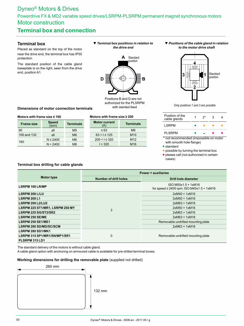
50 Dyneo® Motors & Drives - 5006 en - 2017.05 / g
Terminal box and connection
Terminal boxPlaced as standard on the top of the motor near the drive end, the terminal box has IP55 protection.
The standard position of the cable gland baseplate is on the right, seen from the drive end, position A1.
t Terminal box positions in relation to the drive end
t Positions of the cable gland in relation to the motor drive shaft
2
4
13
A
BD
Standard position
Standard position
Only positions 1 and 3 are possible
Terminal box drilling for cable glands
Power + auxiliariesMotor type Number of drill holes Drill hole diameter
LSRPM 160 LR/MP ISO M50x1.5 + 1xM16for speed ≤ 2400 rpm: ISO M40x1.5 + 1xM16
LSRPM 200 L/LU
3
2xM40 + 1xM16LSRPM 200 L1 2xM50 + 1xM16LSRPM 200 L2/LU2 2xM63 + 1xM16LSRPM 225 ST1/MR1, LSRPM 250 MY 2xM50 + 1xM16LSRPM 225 SG/ST2/SR2 2xM63 + 1xM16LSRPM 250 SE/ME 2xM63 + 1xM16LSRPM 250 SE1/ME1 Removable undrilled mounting plateLSRPM 280 SD/MD/SC/SCM 2xM63 + 1xM16LSRPM 280 SD1/MK1
0 Removable undrilled mounting plateLSRPM 315 SP1/MR1/SN/MP1/SR1PLSRPM 315 LD1
The standard delivery of the motors is without cable gland. A cable gland option with anchoring on armoured cable is available for pre-drilled terminal boxes.
Dimensions of motor connection terminals
Motors with frame size ≤ 160
Frame size Speed (rpm) Terminals
90 all M5100 and 132 all M6
160N ≤ 2400 M6N > 2400 M8
Dyneo® Motors & DrivesPowerdrive FX & MD2 variable speed drives/LSRPM-PLSRPM permanent magnet synchronous motorsMotor construction
Positions B and D are not authorized for the PLSRPM
with slanted feed
Position of the cable glands 1 2* 3 4
LSRPM • • • •PLSRPM • - • •
* not recommended (impossible on motor with smooth hole flange)
• standard• possible by turning the terminal box• please call (not authorized in certain
cases)
Motors with frame size ≥ 200Motor current
(A) Terminals
≤ 63 M663 < I ≤ 125 M10200 < I ≤ 320 M12
I > 320 M16
Working dimensions for drilling the removable plate (supplied not drilled)
260 mm
132 mm
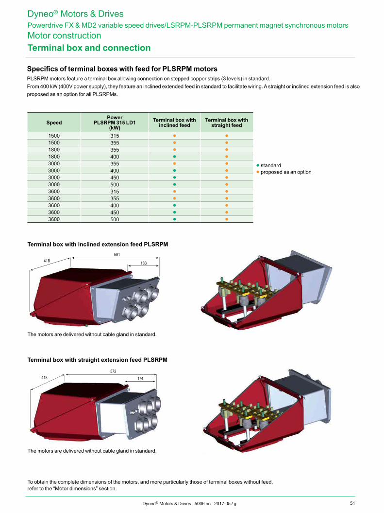
51Dyneo® Motors & Drives - 5006 en - 2017.05 / g
Specifics of terminal boxes with feed for PLSRPM motorsPLSRPM motors feature a terminal box allowing connection on stepped copper strips (3 levels) in standard.From 400 kW (400V power supply), they feature an inclined extended feed in standard to facilitate wiring. A straight or inclined extension feed is also proposed as an option for all PLSRPMs.
Terminal box with inclined extension feed PLSRPM
Terminal box with straight extension feed PLSRPM
To obtain the complete dimensions of the motors, and more particularly those of terminal boxes without feed, refer to the “Motor dimensions” section.
SpeedPower
PLSRPM 315 LD1(kW)
Terminal box with inclined feed
Terminal box with straight feed
1500 315 • •1500 355 • •1800 355 • •1800 400 • •3000 355 • •3000 400 • •3000 450 • •3000 500 • •3600 315 • •3600 355 • •3600 400 • •3600 450 • •3600 500 • •
• standard• proposed as an option
418572
174
418581
183
The motors are delivered without cable gland in standard.
The motors are delivered without cable gland in standard.
Terminal box and connection
Dyneo® Motors & DrivesPowerdrive FX & MD2 variable speed drives/LSRPM-PLSRPM permanent magnet synchronous motorsMotor construction
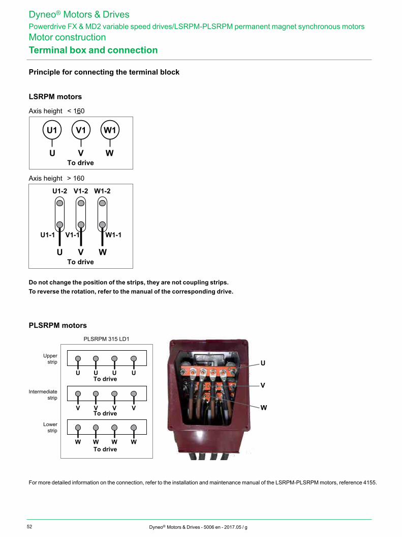
52 Dyneo® Motors & Drives - 5006 en - 2017.05 / g
Principle for connecting the terminal block
LSRPM motors
U1
U V W
U V W
To drive
Axis height < 160
V1 W1
U1-2
To drive
Axis height > 160
V1-2 W1-2
U1-1 V1-1 W1-1
Do not change the position of the strips, they are not coupling strips.To reverse the rotation, refer to the manual of the corresponding drive.
PLSRPM motors
U UTo drive
To drive
To drive
U U
V VV V
W WW W
PLSRPM 315 LD1
Upperstrip
Intermediatestrip
Lowerstrip
U
V
W
For more detailed information on the connection, refer to the installation and maintenance manual of the LSRPM-PLSRPM motors, reference 4155.
Terminal box and connection
Dyneo® Motors & DrivesPowerdrive FX & MD2 variable speed drives/LSRPM-PLSRPM permanent magnet synchronous motorsMotor construction
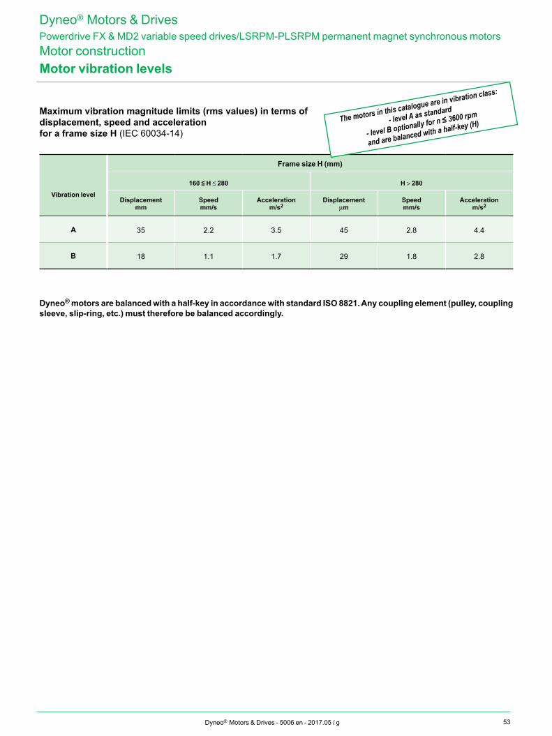
53Dyneo® Motors & Drives - 5006 en - 2017.05 / g
Motor vibration levels
Maximum vibration magnitude limits (rms values) in terms of displacement, speed and acceleration for a frame size H (IEC 60034-14)
Frame size H (mm)
Vibration level
160 ≤ H ≤ 280 H > 280
Displacementmm
Speed mm/s
Accelerationm/s2
Displacementmm
Speed mm/s
Accelerationm/s2
A 35 2.2 3.5 45 2.8 4.4
B 18 1.1 1.7 29 1.8 2.8
Dyneo® Motors & DrivesPowerdrive FX & MD2 variable speed drives/LSRPM-PLSRPM permanent magnet synchronous motorsMotor construction
The motors in this catalogue are in vibration class:
- level A as standard
- level B optionally for n ≤ 3600 rpm
and are balanced with a half-key (H)
Dyneo® motors are balanced with a half-key in accordance with standard ISO 8821. Any coupling element (pulley, coupling sleeve, slip-ring, etc.) must therefore be balanced accordingly.
54 Dyneo® Motors & Drives - 5006 en - 2017.05 / g
Quality commitment
Dyneo® Motors & DrivesPowerdrive FX & MD2 variable speed drives/LSRPM-PLSRPM permanent magnet synchronous motorsGeneral information
ISO 9001 : 2008
Leroy-Somer has entrusted the certification of its expertise to various international organisations.Certification is granted by independent professional auditors, and recognises the high standards of the company's quality assurance procedures. All activities resulting in the final version of the machine have therefore received official certification ISO 9001: 2008 from the DNV. Similarly, our environmental approach has enabled us to obtain certification ISO 14001: 2004.Products for particular applications or those designed to operate in specific environments are also approved or certified by the following organisations: LCIE, DNV, INERIS, EFECTIS, UL, BSRIA, TUV, GOST, that check their technical performance against the various standards or recommendations.
Leroy-Somer's quality management system is based on:
- Control of procedures right from the initial sales offering until delivery to the customer, including design, manufacturing start-up and production
- A total quality policy based on making continuous progress in improving operational procedures, involving all departments in the company in order to give customer satisfaction as regards delivery times, conformity and cost
- Indicators used to monitor procedural performance
- Corrective actions and advancements with tools such as FMECA, QFD, MAVP, MSP/MSQ and Hoshin type improvement workshops on flows, process re-engineering, plus Lean Manufacturing and Lean Office
- Annual surveys, opinion polls and regular visits to customers in order to ascertain and detect their expectations.
Personnel are trained and take part in analyses and actions for continuous improvement of our procedures.
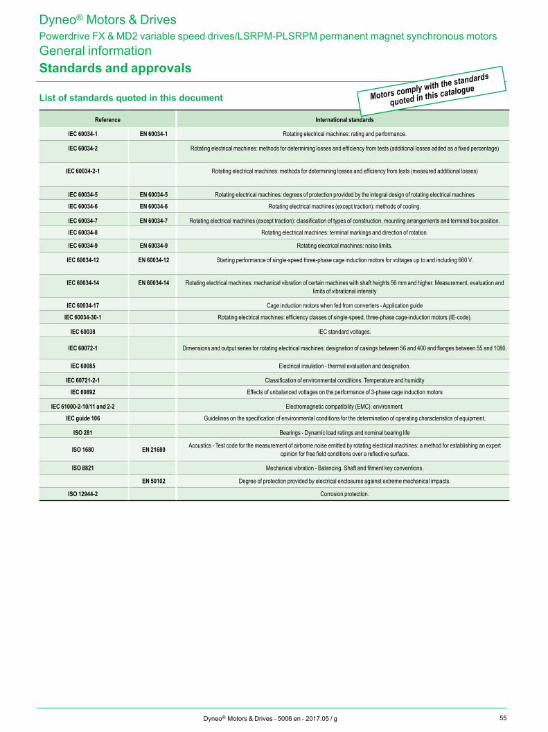
55Dyneo® Motors & Drives - 5006 en - 2017.05 / g
Dyneo® Motors & DrivesPowerdrive FX & MD2 variable speed drives/LSRPM-PLSRPM permanent magnet synchronous motorsGeneral informationStandards and approvals
List of standards quoted in this document
Reference International standards
IEC 60034-1 EN 60034-1 Rotating electrical machines: rating and performance.
IEC 60034-2 Rotating electrical machines: methods for determining losses and efficiency from tests (additional losses added as a fixed percentage)
IEC 60034-2-1 Rotating electrical machines: methods for determining losses and efficiency from tests (measured additional losses)
IEC 60034-5 EN 60034-5 Rotating electrical machines: degrees of protection provided by the integral design of rotating electrical machines
IEC 60034-6 EN 60034-6 Rotating electrical machines (except traction): methods of cooling.
IEC 60034-7 EN 60034-7 Rotating electrical machines (except traction): classification of types of construction, mounting arrangements and terminal box position.
IEC 60034-8 Rotating electrical machines: terminal markings and direction of rotation.
IEC 60034-9 EN 60034-9 Rotating electrical machines: noise limits.
IEC 60034-12 EN 60034-12 Starting performance of single-speed three-phase cage induction motors for voltages up to and including 660 V.
IEC 60034-14 EN 60034-14 Rotating electrical machines: mechanical vibration of certain machines with shaft heights 56 mm and higher. Measurement, evaluation and limits of vibrational intensity
IEC 60034-17 Cage induction motors when fed from converters - Application guide
IEC 60034-30-1 Rotating electrical machines: efficiency classes of single-speed, three-phase cage-induction motors (IE-code).
IEC 60038 IEC standard voltages.
IEC 60072-1 Dimensions and output series for rotating electrical machines: designation of casings between 56 and 400 and flanges between 55 and 1080.
IEC 60085 Electrical insulation - thermal evaluation and designation.
IEC 60721-2-1 Classification of environmental conditions. Temperature and humidity
IEC 60892 Effects of unbalanced voltages on the performance of 3-phase cage induction motors
IEC 61000-2-10/11 and 2-2 Electromagnetic compatibility (EMC): environment.
IEC guide 106 Guidelines on the specification of environmental conditions for the determination of operating characteristics of equipment.
ISO 281 Bearings - Dynamic load ratings and nominal bearing life
ISO 1680 EN 21680 Acoustics - Test code for the measurement of airborne noise emitted by rotating electrical machines: a method for establishing an expert opinion for free field conditions over a reflective surface.
ISO 8821 Mechanical vibration - Balancing. Shaft and fitment key conventions.
EN 50102 Degree of protection provided by electrical enclosures against extreme mechanical impacts.
ISO 12944-2 Corrosion protection.
Motors comply with the standards
quoted in this catalogue
Motors comply with the standards
quoted in this catalogue
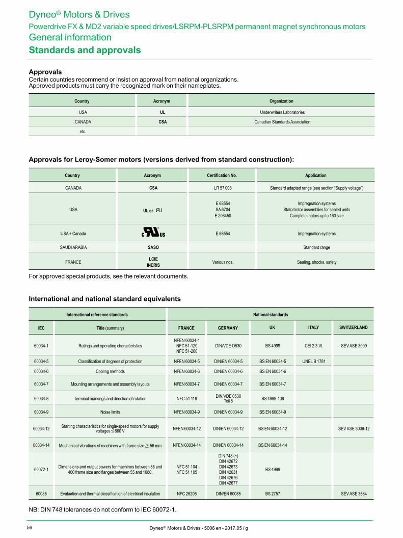
56 Dyneo® Motors & Drives - 5006 en - 2017.05 / g
Dyneo® Motors & DrivesPowerdrive FX & MD2 variable speed drives/LSRPM-PLSRPM permanent magnet synchronous motorsGeneral informationStandards and approvals
Approvals Certain countries recommend or insist on approval from national organizations.Approved products must carry the recognized mark on their nameplates.
Country Acronym Organization
USA UL Underwriters Laboratories
CANADA CSA Canadian Standards Association
etc.
Approvals for Leroy-Somer motors (versions derived from standard construction):
Country Acronym Certification No. Application
CANADA CSA LR 57 008 Standard adapted range (see section “Supply voltage”)
USA UL or E 68554SA 6704E 206450
Impregnation systemsStator/rotor assemblies for sealed units
Complete motors up to 160 size
USA + Canada C US E 68554 Impregnation systems
SAUDI ARABIA SASO Standard range
FRANCE LCIEINERIS Various nos. Sealing, shocks, safety
For approved special products, see the relevant documents.
International and national standard equivalents
International reference standards National standards
IEC Title (summary) FRANCE GERMANY UK ITALY SWITZERLAND
60034-1 Ratings and operating characteristics NFEN 60034-1
NFC 51-120NFC 51-200
DIN/VDE O530 BS 4999 CEI 2.3.VI. SEV ASE 3009
60034-5 Classification of degrees of protection NFEN 60034-5 DIN/EN 60034-5 BS EN 60034-5 UNEL B 1781
60034-6 Cooling methods NFEN 60034-6 DIN/EN 60034-6 BS EN 60034-6
60034-7 Mounting arrangements and assembly layouts NFEN 60034-7 DIN/EN 60034-7 BS EN 60034-7
60034-8 Terminal markings and direction of rotation NFC 51 118 DIN/VDE 0530Teil 8 BS 4999-108
60034-9 Noise limits NFEN 60034-9 DIN/EN 60034-9 BS EN 60034-9
60034-12 Starting characteristics for single-speed motors for supply voltages ≤ 660 V NFEN 60034-12 DIN/EN 60034-12 BS EN 60034-12 SEV ASE 3009-12
60034-14 Mechanical vibrations of machines with frame size ≥ 56 mm NFEN 60034-14 DIN/EN 60034-14 BS EN 60034-14
60072-1 Dimensions and output powers for machines between 56 and 400 frame size and flanges between 55 and 1080.
NFC 51 104NFC 51 105
DIN 748 (~)DIN 42672DIN 42673DIN 42631DIN 42676DIN 42677
BS 4999
60085 Evaluation and thermal classification of electrical insulation NFC 26206 DIN/EN 60085 BS 2757 SEV ASE 3584
NB: DIN 748 tolerances do not conform to IEC 60072-1.
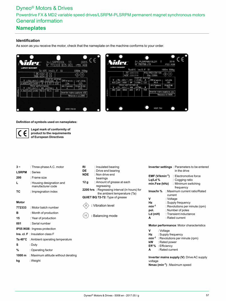
57Dyneo® Motors & Drives - 5006 en - 2017.05 / g
Dyneo® Motors & DrivesPowerdrive FX & MD2 variable speed drives/LSRPM-PLSRPM permanent magnet synchronous motorsGeneral informationNameplates
IdentificationAs soon as you receive the motor, check that the nameplate on the machine conforms to your order.
Definition of symbols used on nameplates:
Legal mark of conformity of product to the requirements of European Directives
3 ~ : Three-phase A.C. motor
LSRPM : Series
200 : Frame size
L : Housing designation and manufacturer code
TC : Impregnation index
Motor
772333 : Motor batch number
B : Month of production
15 : Year of production
001 : Serial number
IP55 IK08 : Ingress protection
Ins. cl. F : Insulation class F
Ta 40°C : Ambient operating temperature
S : Duty
% : Operating factor
1000 m : Maximum altitude without derating
kg : Weight
RI : Insulated bearingDE : Drive end bearingNDE : Non drive end bearings12 g : Amount of grease at each
regreasing2200 hrs : Regreasing interval (in hours) for
the ambient temperature (Ta)QUIET BQ 72-72: Type of grease
A H: Vibration level
A H : Balancing mode
Inverter settings : Parameters to be entered in the drive
EMF (V/kmin-1) : Electromotive forceLq/Ld % : Cogging ratiomin.Fsw (kHz) : Minimum switching
frequencyImax/In % : Maximum current ratio/Rated
currentV : VoltageHz : Supply frequencymin-1 : Revolutions per minute (rpm)pol. : Number of polesLd (mH) : Transient inductanceA : Rated current
Motor performance: Motor characteristics
V : VoltageHz : Supply frequencymin-1 : Revolutions per minute (rpm)kW : Rated powerEff % : EfficiencyA : Rated current
Inverter mains supply (V): Drive AC supply voltageNmax (min-1) : Maximum speed
58 Dyneo® Motors & Drives - 5006 en - 2017.05 / g
The Leroy-Somer configurator can be used to choose the most suitable motors and drives and provides the technical specifications and corresponding drawings.
Register online atwww.leroy-somer.com/fr/solutions_et_services/systemes_entrainement/configurateur
• Help with product selection• Print-outs of technical specifications• Print-outs of 2D and 3D CAD files• The equivalent of 300 catalogs in
10 languages
Dyneo® Motors & DrivesPowerdrive FX & MD2 variable speed drives/LSRPM-PLSRPM permanent magnet synchronous motorsGeneral informationConfigurator

59Dyneo® Motors & Drives - 5006 en - 2017.05 / g
Notes

5006 en - 2017.05 / g
www.nidecautomation.com
Connect with us at:twitter.com/Leroy_Somerfacebook.com/leroysomer.nidecyoutube.com/user/LeroySomerOfficieltheautomationengineer.com (blog)
Moteurs Leroy-Somer SAS. Headquarters: Bd Marcellin Leroy, CS 10015, 16915 Angoulême Cedex 9, France. Share Capital: 65 800 512 €, RCS Angoulême 338 567 258.


