88
Coal Dehydration Sachin V. Jangam and Arun S. Mujumdar .... A compilation of relevant publications and technical reports

Coal Dehydration
Sachin V. Jangam and Arun S. Mujumdar
....A compilation of relevant publications and technical reports


COAL DEHYDRATION

COAL DEHYDRATION
Editors: Sachin V. Jangam and Arun S. Mujumdar
2010
COAL DEHYDRATION Copyright © 2010 All rights reserved. No part of this publication may be reproduced or distributed in any form or by any means, or stored in a database or retrieval system, without the prior written permission of the copyright holder. This book contains information from recognized sources and reasonable efforts are made to ensure their reliability. However, the authors, editor and publisher do not assume any responsibility for the validity of all the materials or for the consequences of their use.
PREFACE
It is generally accepted that coal will remain the most significant fossil fuel for
generation of electrical power in most parts of the world despite numerous ecological limitations associated with its use. The most significant concerns are related to the global warming and climate change issues due to greenhouse gas emissions from coal combustion and also the release of noxious emissions. Clean coal technologies are being developed around the world to enhance combustion, gasification as well as coal liquefaction processes. All of these processes require low moisture coal. It so happens that there is abundant supply of low rank coals containing high moisture content. Their low calorific value and higher costs involved in transporting the water along with coal have discouraged their industrial use in the past. With the rise in demand for coal it is increasingly important to access such coal by upgrading it. The simplest way to upgrade it is to remove the water associated with coal either thermally or nonthermally. Numerous processes have been proposed in the literature for dehydrating coal but their techno-economics are not known.
This compilation of our reports consists of several papers which our group at M3TC
has written about drying of coal. Specifically we provide concise overviews of most (not all) of the dehydration technologies that have been published in public domain. We have covered archival literature as well as patents. Some of the work is not peer-reviewed or tested independently. Some of the newer ideas have not been investigated fully and so may be subject to modification later. However, we believe it is useful for both academics and industry interested in coal technologies to be aware of the diverse techniques that have been suggested and studied to varying degrees.
We plan to update this e-book at regular intervals so readers may wish to visit the
site regularly. Arun Sadashiv Mujumdar, NUS, Singapore Sachin Vinayak Jangam, NUS, Singapore Editors


Index
Chapter No Title / Authors Page No
01 Critical Assessment of Drying of Low Rank Coal S.V. Jangam, J.V.M. Kuma and A.S. Mujumdar
01
02 Review of Patents on Drying of Low Rank Coal H.B. Osman, S.V. Jangam and A.S. Mujumdar
29
03 Simprosys for Energy Evaluation of Coal Drying Flowsheet S.V. Jangam, Z.X. Gong and A.S. Mujumdar
53
04 Drying in Mineral Processing Industry: Potential for Innovation W. Zhonghua and A.S. Mujumdar
65


Critical Assessment of Drying of Low Rank Coal
S.V. Jangam, J.V.M. Kuma and A.S. Mujumdar
Minerals, Metals and Materials technology Centre, National university of Singapore
Contents
1. INTRODUCTION ............................................................................................................................ 1
2. NEED FOR LRC DRYING ............................................................................................................... 4
3. FACTORS OF CONCERN IN LRC DRYING ................................................................................ 4
4. STATE OF ART OF LRC DRYING ................................................................................................ 5
4.1. Conventional Evaporative Dryers ................................................................................................................................... 5 4.2. Superheated Steam Drying ................................................................................................................................................. 7
5. EMERGING TECHNIQUES ............................................................................................................ 9
5.1. Screw Conveyor Dryer (SCD) ............................................................................................................................................ 9 5.2. Microwave Drying ............................................................................................................................................................... 10 5.3. Impinging Stream Drying (ISD) ..................................................................................................................................... 11 5.4. Novel Fluidized Bed Dryer............................................................................................................................................... 11 5.5. Developing Energy Efficient Drying Options for Coal ......................................................................................... 12 5.5.1. Renewable Sources of Energy for Coal Drying ................................................................................................... 12 5.5.2. Use of Waste Heat ............................................................................................................................................................ 13 5.6. Use of Coal Mine Methane ................................................................................................................................................ 14 5.7. Processing of LRC prior to drying ................................................................................................................................ 15 5.8. Displacement drying of coal ........................................................................................................................................... 15
6. USE OF ADVANCED COMPUTATIONAL TOOLS FOR DEVELOPING INNOVATIVE
DRYING SYSTEM FOR LRC ........................................................................................................... 16
7. EFFECT ON SULPHUR CONTENT DURING DRYING ......................................................... 18
8. SAFETY IN COAL DRYING ........................................................................................................ 18
9. CASE STUDY:(PRELIMINARY EVALUATION OF AN EMERGING TECHNIQUE - SCD)
.............................................................................................................................................................. 19
10. SUSTAINABILITY IN LRC DRYING ...................................................................................... 22
CLOSING REMARKS ........................................................................................................................ 23


Critical Assessment of Drying of Low Rank Coal
3
1. INTRODUCTION
Coal is the world's most important source of energy fueling around 40% of the power
stations around the world besides its use as a starting material for many chemical syntheses.[1,2]
It is commonly agreed that coal pits will be mined more intensively and in more numbers in the
coming years and that lignite and hard coals will be the major energy suppliers until 2100.[3]
This is mainly because of the increased need of electricity and increase in other applications of
coal. For example, China's electricity consumption is expected to double by 2020.[4] Though the
use of other sources of electricity is increasing and improving every year the demand for coal in
this sector will continue for many decades to come as it is the cheapest fossil fuel and most
abundant source for power generation. The US Department of Energy statistics indicate that
currently known recoverable coal all over the globe will last over 150 years at the current
consumption rate.[4]
Coals are generally classified as high and low rank depending on their properties, especially
heating value, moisture content, coalification time, impurities etc. According to Katalambula and
Gupta[5], coal is called low-grade if it has one or more negative properties relative to its use in
power plants. Although the major part of the global coal reserves, about 45%, consist of Low
Rank Coal (LRC, also known as brown coal, mainly lignite), it is not exploited much because of its
inherent poor properties such as higher moisture content and hence low calorific value, high ash
content and low carbon content.[1,6-7] LRCs can have moisture content from 25% to as high as
66% in some of the Victorian coals.[7] Currently LRC's are used mainly for electricity generation
but their use for other applications will increase in the near future as it does have certain
advantages over black coal. Wilson et al.[6] have listed out some of these which include: low
mining cost, high reactivity, high amount of volatiles and low pollution-forming impurities such
as sulphur, nitrogen and heavy metals. They also have proposed some of the potential
applications of upgraded LRC which include: pyrolysis, gasification, liquefaction processes and
even formulations of coal-water slurries as fuel. LRCs can be used to replace more expensive
bituminous coals, either as blending components with high rank coal in existing boilers, or in
new boilers designed with flexibility to use LRC. But the high amount of moisture in LRC leads to
higher energy requirements during combustion, high amount of stack gas flow, lower plant
efficiency, high transportation cost and potential safety hazards during transportation and
storage etc. It is not cost-effective to process LRC if it is transported to industrial site without
drying although the mining cost is low. The presence of moisture causes reduction in friability of
coal, difficulty in blending and pneumatic transportation.
Critical Assessment of Drying of Low Rank Coal
4
2. NEED FOR LRC DRYING
All applications of lignite require drying as a pre-processing step.[1] Drying of lignite prior to
transportation can result in major savings in transportation costs. For example, Lucarelli[8] has
reported that, a coal producer can save $0.19/GJ of energy on storage and handling and
transportation costs if LRC is dried from 35% to just 25% moisture content, while, the savings
on logistics costs could be as high as $7 million per year for a 600 MW plant. An important issue
to be considered while drying LRC is the energy used to remove the huge amount of moisture
from comparatively low value coal type. An energetically efficient, cost-effective and safe drying
process can result in improvement of the overall efficiency and lead to higher returns. Safe
drying at minimal cost and energy consumption is the best way to upgrade low rank coals.
Although vendors of conventional drying equipment such as rotary and fluid bed dryers also
quote dryers for coal, they are typically not specifically designed for LRC with possible
exceptions. We believe that a careful and systematic R&D evaluation is needed to evaluate dryers
for LRCs.
3. FACTORS OF CONCERN IN LRC DRYING
Depending on the dryer type and the drying medium used, the properties of dried LRC can
vary. The principal difficulties associated with LRC drying are safety issues and spontaneous
combustion.[9] Conventional drying processes can be used, with extra care to ensure safe
operation to mitigate possible fire and explosion hazards, if the coal is dried at the plant site just
prior to its use. Karthikeyan et al.[9] have carried out laboratory scale drying studies and
reported that LRCs are highly susceptible to moisture re-adsorption if not stored properly or not
utilized soon after the drying process. They also have reported 10-20% increase in fine particle
size during LRC drying which ultimately results in faster moisture adsorption due to additional
exposed surfaces. If drying is carried out at mine sites to reduce the cost of transportation, re-
adsorption of moisture during storage and during transportation is a major concern. Although,
Karthikeyan[10] has reported various methods to minimize moisture re-adsorption such as high
temperature treatment and coating of dried coal using bitumen, with or without solvent, it is
difficult to determine if coating will be a cost-effective option when massive quantities of coal
are to be handled.
Karthikeyan[10] discusses the important problem of spontaneous combustion of low rank
coal which is a result of self-heating caused by the reactive nature of LRC. The wetting of coal
during storage results in an exothermic reaction. The chances of spontaneous combustion are
higher for dried hygroscopic low rank coals. This possibility further increases if the particle size
is small as it is a surface phenomenon. In general, the finer the particles, the greater is the

Critical Assessment of Drying of Low Rank Coal
5
tendency for spontaneous combustion. Hence selecting the drying method and the drying media
is very important for LRC drying. Although use of superheated steam reduces the chances of
spontaneous combustion because of the absence of oxygen, the cost involvement in such
processes is high due to the complexity in design and operation of such dryers for very high
throughput. At lower production rates steam drying is thought to be an expensive operation. Dry
low rank coal of fine particles is more susceptible to spontaneous combustion.
Loss of volatiles during drying is also a problem. Conventional drying methods use rather
high temperatures for drying. Use of very high temperatures can result in loss of useful volatile
matter from LRC which in turn reduces its calorific value while also enhancing fire risk. The use
of air at low temperature or low level of vacuum and indirect heating can reduce chances of
spontaneous combustion as well the loss of volatiles but this lowers the drying rate.
4. STATE OF ART OF LRC DRYING
The level of moisture to be achieved upon drying LRCs depends mainly on the end
application; it varies from as low as 0% for hydrogenation processes to 15% for briquetting and
gasification processes.[1,2] The detailed description of the allowed moisture in coal for different
applications can be found elsewhere.[2] The selection of dryer type for any application is a critical
step, especially for drying of LRC the selection is very crucial as high amount of moisture is to be
removed from low value product. In addition one has to take various issues into consideration
such as the spontaneous combustion, moisture re-adsorption and loss of volatiles as discussed
earlier.
Pikon and Mujumdar[2] have discussed various dryer types for coal, their advantages and
limitations etc in the Handbook of Industrial Drying. Table 1 lists some of the conventional
dryers used for coal drying along with their merits and limitations. Unfortunately, only few of
these studies have published relevant data to ensure applications on industrial scale in a cost
effective way. No cost data are available. No data are available also on the physical or chemical
properties of the wet coal and dried coal before and after drying. Mujumdar[11] in his Handbook
of Industrial Drying covers a very large assortment of dryers, both conventional and innovative,
although not all are suitable for coal drying.
4.1. Conventional Evaporative Dryers
Conventional evaporative dryers use air or combustion gases as the drying media with
temperatures of about 700-900°C at the dryer inlet and 60-120°C at the outlet.[1] Commonly
used dryers are fluidized bed, vibrated bed, flash dryers and rotary dryers. Such high
temperatures should not be used for coal drying as it is susceptible to spontaneous ignition and
loss of volatiles. Hence, indirectly heated rotary dryer was the common choice in old days.

Critical Assessment of Drying of Low Rank Coal
6
Rotary dryers were also reported to have higher energy efficiency and lower energy
consumption per unit mass of coal dried compared to other conventional dryers such as
fluidized bed dryer.[1,6] Vibrated bed dryer was reported to have better energy efficiency
compared to conventional fluidized bed. Attrition and gas cleaning requirement was also
minimized using vibrated dryer. Generally a single dryer does not meet the objectives in case of
LRC as the 20% strongly bound moisture is difficult to get rid of. Multi-stage drying system is
suggested for LRC drying. Karthikeyan et al.[1] have reported that the rotary dryer can be used as
a first stage dryer, which works as a disintegrator followed by the second stage drying using
either fluid bed dryer or rotary dryer, which can work as heat recovery device as well as cooler.
Recently pulsed combustion dryer and pulverizer dryer have been reported to have certain
merits in coal drying. Pulse combustion dryer for example has certain advantages such as high
drying rates, high thermal efficiency, improved product quality and less environment impact.
However, it has certain limitations such as the difficulties in scale-up, noise problem and the cost
involved if it is to be used for very high throughputs. There have been few reported studies on
Pulver dryer. The energy created during impact between high speed impeller blades and coal,
while air stream can be used to dry the products. However, its use for high throughput
application is not attractive. Erosion of the impeller blades can be a problem. Also use of
electrical energy to rotate the high rpm impeller to break up the material and also provide
thermal energy through dissipation of mechanical energy is also unattractive economically and
thermodynamically for LRC application.
Use of superheated steam is attractive energetically since, in principle, energy in the exhaust
stream can be recovered more easily while the fire and explosion hazard is also eliminated.
There are reports of use of superheated steam fluid bed dryer for pulverized coal drying in South
Africa.
Table 1 summarizes some relevant data for various dryer types for coal from published
sources. Only the key advantages and limitations are listed in the interest of brevity.
Table 1: Comparison of conventional drying techniques for Coal
Dryer type Advantages Limitations
Fluid bed dryer[1,7] Intensive drying due to good
mixing
High pressure drop;
Attrition
Spouted bed dryer[1] Very good heat and mass
transfer rates;
Scale-up issues;
Limited particle size
Vibrated bed dryer[6] Low velocity required for
fluidization
Moving parts
Pneumatic dryers [7] Simple construction Attrition

Critical Assessment of Drying of Low Rank Coal
7
Rotary Dryer[7,12,13] Drying along with
disintegration; internal
heating with coils; flue gas
with low O2 as drying medium
to eliminate fire hazard
High maintenance
Rotary tube dryers[2,7] Indirect heating; no fire
hazard; good efficiency
Capital-intensive
Superheated steam
using various
types[6,14-16]
High thermal efficiency; No
danger of fire or explosion,
Energy efficient.
Suited for high capacity
continuous operation; Energy in
exhaust should be usable
elsewhere in plant.
Horizontal agitated
bed dryer: Heating
through jacket or
screw[11]
Possibility of indirect heating
though shaft and jacket; very
low drying medium flow rate
needed
High maintenance; power
requirements
Belt dryer[2,7] Compact construction; Simple
design; Drying at lower
temperatures
Capacity may be limited; Large
footprint.
Pulsed Combustion
Drying[17]
Short drying time; high drying
efficiency; environmentally
friendly operation
Noise problem;
Scale-up issues;
Fire hazard
4.2. Superheated Steam Drying
Various researchers have reported number of advantages of SHSD such as reduced risk of
spontaneous ignition/fire due to absence of oxygen, increased drying rates, reduction in dust
emission, increased energy efficiency and improved grindability.[2,6,15,16] It was also observed that
the sulphur and sodium content may be reduced during superheated steam drying above 300°C.
Chen et al.[18] carried out mathematical analysis of superheated steam drying of single particle as
well as in fluidized bed[19] and reported that the most significant operating parameters deciding
the process efficiency are the steam temperature and the initial moisture content of the coal
sample. They also have carried out comparison of drying rates with air and found that there
exists inversion temperature above which the drying sing superheated steam is faster. Professor
Potter from Monash University was the first to use superheated steam fluidized bed drying at
commercial scale. Since then the SHSD technology has improved to increase the efficiency and to
reduce the operating cost. One of the recent technologies developed is the WTA (Wirbelshicht-
Critical Assessment of Drying of Low Rank Coal
8
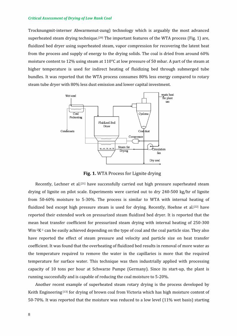
Trocknungmit-interner Abwarmenut-zung) technology which is arguably the most advanced
superheated steam drying technique.[20] The important features of the WTA process (Fig. 1) are,
fluidized bed dryer using superheated steam, vapor compression for recovering the latent heat
from the process and supply of energy to the drying solids. The coal is dried from around 60%
moisture content to 12% using steam at 110°C at low pressure of 50 mbar. A part of the steam at
higher temperature is used for indirect heating of fluidizing bed through submerged tube
bundles. It was reported that the WTA process consumes 80% less energy compared to rotary
steam tube dryer with 80% less dust emission and lower capital investment.
Fig. 1. WTA Process for Lignite drying
Recently, Lechner et al.[21] have successfully carried out high pressure superheated steam
drying of lignite on pilot scale. Experiments were carried out to dry 240-500 kg/hr of lignite
from 50-60% moisture to 5-30%. The process is similar to WTA with internal heating of
fluidized bed except high pressure steam is used for drying. Recently, Hoehne et al.[22] have
reported their extended work on pressurized steam fluidized bed dryer. It is reported that the
mean heat transfer coefficient for pressurized steam drying with internal heating of 250-300
Wm-2K-1 can be easily achieved depending on the type of coal and the coal particle size. They also
have reported the effect of steam pressure and velocity and particle size on heat transfer
coefficient. It was found that the overheating of fluidized bed results in removal of more water as
the temperature required to remove the water in the capillaries is more that the required
temperature for surface water. This technique was then industrially applied with processing
capacity of 10 tons per hour at Schwarze Pumpe (Germany). Since its start-up, the plant is
running successfully and is capable of reducing the coal moisture to 5-20%.
Another recent example of superheated steam rotary drying is the process developed by
Keith Engineering [13] for drying of brown coal from Victoria which has high moisture content of
50-70%. It was reported that the moisture was reduced to a low level (11% wet basis) starting

Critical Assessment of Drying of Low Rank Coal
9
with around 61%. The feed rate of the brown coal was 23-46 kg/h and steam temperature was
180-230°C with a drum rate of 3-6 rpm. Superheated steam drying was used for drying of
Indonesian coal of relatively low moisture content but rich in sulphur.[16] The steam temperature
of 300°C was found to be sufficient to remove the moisture to expected level.
However, these types of dryers are mainly suited for very large scale power plant
applications on site. The investment costs are very high although they report high efficiency and
safe operation. There is insufficient data on energy consumption and cost of drying per ton of
coal. Of course, safety of operation is enhanced in SHSD. Please refer to Mujumdar[11] for an in-
depth discussion of superheated steam drying.
5. EMERGING TECHNIQUES
The following section discusses some alternative dryers and potential ways to make LRC drying
cost-effective.
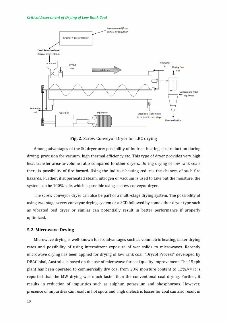
5.1. Screw Conveyor Dryer (SCD)
The screw conveyor dryer (Fig 2) consists of a jacketed conveyor in which material is
simultaneously heated and dried as it is conveyed.[23] The heating medium is usually hot water,
steam, or a high-temperature heat transfer medium such as pot oil, fused salt, or Dowtherm heat
transfer fluid. The flights and shaft may be hollow, through which the heating medium flows to
provide greater heat transfer area with minimum space requirements. Screw conveyors, due to
their versatility in gentle handling, can be used for drying a large variety of solid particles
ranging from free-flowing to relatively less free-flowing ones and from fine powder to lumpy,
sticky, and fibrous materials.[23]
Critical Assessment of Drying of Low Rank Coal
10
Fig. 2. Screw Conveyor Dryer for LRC drying
Among advantages of the SC dryer are: possibility of indirect heating, size reduction during
drying, provision for vacuum, high thermal efficiency etc. This type of dryer provides very high
heat transfer area-to-volume ratio compared to other dryers. During drying of low rank coals
there is possibility of fire hazard. Using the indirect heating reduces the chances of such fire
hazards. Further, if superheated steam, nitrogen or vacuum is used to take out the moisture, the
system can be 100% safe, which is possible using a screw conveyor dryer.
The screw conveyor dryer can also be part of a multi-stage drying system. The possibility of
using two-stage screw conveyor drying system or a SCD followed by some other dryer type such
as vibrated bed dryer or similar can potentially result in better performance if properly
optimized.
5.2. Microwave Drying
Microwave drying is well-known for its advantages such as volumetric heating, faster drying
rates and possibility of using intermittent exposure of wet solids to microwaves. Recently
microwave drying has been applied for drying of low rank coal. “Drycol Process” developed by
DBAGlobal, Australia is based on the use of microwave for coal quality improvement. The 15 tph
plant has been operated to commercially dry coal from 28% moisture content to 12%.[24] It is
reported that the MW drying was much faster than the conventional coal drying. Further, it
results in reduction of impurities such as sulphur, potassium and phosphorous. However,
presence of impurities can result in hot spots and, high dielectric losses for coal can also result in
Critical Assessment of Drying of Low Rank Coal
11
fire hazard during drying. Further, it is difficult to comment on the cost involved for handling
huge amount of coals. Intermittent MW drying is a possible option to remove moisture efficiently
during final stages of coal drying.
5.3. Impinging Stream Drying (ISD)
Impinging stream dryers are novel alternatives to flash dryers for particulate materials with
very high drying loads. Nevertheless, studies on ISD are still partial or limited to very few
applications. In these type of dryers the intensive collision of opposed streams creates a zone
that offers very huge heat, mass and momentum transfer.[25] Hence rapid removal of surface
moisture is possible. Other advantages of impinging dryers are smaller foot prints and high
robustness due to absence of any moving part. However, the design of a such system is very
important particularly the feeding arrangement and the design of the impinging pipes affect the
value of volumetric heat transfer coefficient and in turn the water evaporation rate. Recently,
Choicharoen et al.[25] have carried out performance evaluation of impinging dryer with Okara as
a ideal material and concluded that ISD gives very high volumetric heat transfer coefficient and
the performance depends on the aforementioned parameters. All these advantages of ISD allows
one to consider it as a possible option for drying LRC provided it can handle huge throughputs
which can be a main limitation. Another limitation could be the scale of velocities used.
5.4. Novel Fluidized Bed Dryer
Fluidized bed dryers have been traditionally used for drying of coal with various options
such as air, flue gases and superheated steam.[2,6] There have been numerous attempts to
improve the performance of fluidized bed dryers for coal such as indirect heat transfer to the
solid bed, use of high pressure (in case of superheated steam drying). However, the performance
of fluidized beds depends highly on the size and shape of the particles to be handled which
decides the quality of fluidization. This problem can commonly occur during coal drying as the
particles can be highly irregular in shape which results in channelling and slugging of bed. The
quality of fluidization can be improved either by mechanical vibrations, agitation or with a
pulsating flow of fluidizing gas.[11] Vibrated beds have been widely used for different application
and recently agitated bed dryers have immerged as a better option as it can provide better
performance because of indirect heating of bed. In case of pulsating fluidized beds, the
fluidization velocity pulsates with time in the form of regular or irregular patterns.[26] Many
studies have shown that pulsed fluidization can improve the fluidization quality as it eliminates
the problem of channelling and slugging. Li et al.[26] reported that the pulsating fluidized beds
result into reduced bubble size and better gas-particle contact. Hence, some difficult-to-dry
materials can be easily handled. Li et al.[26] 2010 have also carried out the theoretical study of the

Critical Assessment of Drying of Low Rank Coal
12
hydrodynamic behaviour of these dryers using two-fluid model for three pulsating frequencies
of 0.4, 4 and 40Hz. It was concluded that 40Hz resulted in to normal fluidization. In addition, the
bed expansion was more in pulsating fluidized bed dryer with low bed fluctuation rates which
means improved fluidization quality. These types of fluidized bed dryers can replace traditional
FBDs in for coal applications and can be considered as a better option to develop more efficient
drying system.
5.5. Developing Energy Efficient Drying Options for Coal
It is well known fact that the drying is a highly energy intensive unit operation, which
ultimately contributes to the emission of green house gases.[11,27] Drying of LRC also involves
removal of high amount of moisture from a low value coal. Baker[27] has explained the reasons
and ways to develop the efficient drying system. He has pointed out the need to reduce the
energy consumption of dryers as a part of a global effort to control the emission of greenhouse
gases. In many countries, the government provides intensives for energetically improved
technologies. Baker describes that legislations, monitoring of dryers and drying process
intensification are three interrelated factors which affect the energy consumption. Further,
Baker has recommended various ways to improve energy efficiency such as, periodic auditing,
process monitoring, use of waste heat, renewable energy, recovering energy from dryer exhaust,
recirculation of drying medium which can result in better energy efficiency. Recently, Kudra et
al.[28] have suggested simple excel-based calculation tool to examine the energy performance of
convective dryers. The calculated values of specific energy consumption and energy efficiency
can then be used to compare with the ideal adiabatic dryers to identify the scope for
improvement. Following are the ways to improve energy efficiency in coal drying.
5.5.1. Renewable Sources of Energy for Coal Drying
Use of renewable sources of energy can compensate somewhat for depleting sources of
energy. Solar energy is commonly used for agricultural drying applications. Depending upon the
geographical location of the coal drying plant, various renewable sources of energy can be used
for LRC drying to make it cost-effective, although there are few reports of such efforts on a big
scale yet. Solar dryers have been used for drying of Victorian brown coal in past[6] but they
suffered from constraints such as variable climatic conditions and large space requirements
when massive quantities of coal are to be processed. However, during conveying of coal from
mine site to barge port, where long covered conveyors are often used, suitably designed solar
collectors can in principle be utilized to supply heat needed to remove small amounts of
moisture from LRC. According to karthikeyan et al.[1] coal can also be dried during road transport
or shipping over long distances using renewable energy sources, which may only need special

Critical Assessment of Drying of Low Rank Coal
13
design of the container and air guides. Ambient air drying during storage or conveying is also a
feasible idea if the air is not saturated.
Atmospheric air can be heated and used as is to remove moisture during conveying. This
needs some simple design modifications of the conveying systems already used. Even a small
reduction in moisture can result into large savings when coal is combusted. Use of wind energy
and hydrothermal energy for generation of electricity in coal preparation plants is another
possibility of making the process cost-effective and eco-friendly. To authors' knowledge this has
not yet been attempted in practice. Since renewable energy sources like solar and wind are
necessarily intermittent and seasonal they need backup heating or storage systems that make
the system more expensive in some parts of the world. Mathematical modeling can be used to
assist with the design, optimization and operation of such systems. The effect of varying air
temperature and humidity can be numerically evaluated for bed coal particles of varying
moisture content and temperature along the bed height. This is an area of R&D that appears to
be untapped so far but deserves serious attention.
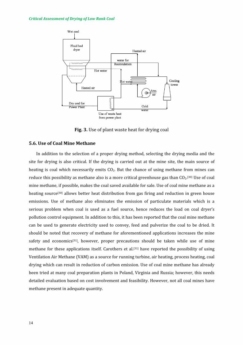
5.5.2. Use of Waste Heat
LRC can also be dried at the processing plant site using waste heat from the plant as well as
the flue gases for drying.[29] He has reported that the use of ambient air heated using the waste
heat from condenser (Fig. 3) can result in 3.8% increase in the plant efficiency. In another
instance, low-grade waste heat was used to evaporate a part of moisture from lignite feedstock
at a 550 MW unit at Coal Creek Station, North Dakota.[1] Improved boiler and unit performance
was achieved in this test by removing 6% of fuel moisture to 2.6-2.8%. This performance
improvement is due to reduction in moisture evaporation loss and decrease in auxiliary power
requirements. The WTA process explained previously also uses internal waste heat to pre-heat
the coal feed-stock. This results in overall performance improvement.
Critical Assessment of Drying of Low Rank Coal
14
Fig. 3. Use of plant waste heat for drying coal
5.6. Use of Coal Mine Methane
In addition to the selection of a proper drying method, selecting the drying media and the
site for drying is also critical. If the drying is carried out at the mine site, the main source of
heating is coal which necessarily emits CO2. But the chance of using methane from mines can
reduce this possibility as methane also is a more critical greenhouse gas than CO2.[30] Use of coal
mine methane, if possible, makes the coal saved available for sale. Use of coal mine methane as a
heating source[30] allows better heat distribution from gas firing and reduction in green house
emissions. Use of methane also eliminates the emission of particulate materials which is a
serious problem when coal is used as a fuel source, hence reduces the load on coal dryer’s
pollution control equipment. In addition to this, it has been reported that the coal mine methane
can be used to generate electricity used to convey, feed and pulverize the coal to be dried. It
should be noted that recovery of methane for aforementioned applications increases the mine
safety and economics[31], however, proper precautions should be taken while use of mine
methane for these applications itself. Carothers et al.[31] have reported the possibility of using
Ventilation Air Methane (VAM) as a source for running turbine, air heating, process heating, coal
drying which can result in reduction of carbon emission. Use of coal mine methane has already
been tried at many coal preparation plants in Poland, Virginia and Russia; however, this needs
detailed evaluation based on cost involvement and feasibility. However, not all coal mines have
methane present in adequate quantity.
Critical Assessment of Drying of Low Rank Coal
15
5.7. Processing of LRC prior to drying
Processing of coal prior to drying in different forms such as briquettes, pellets or
extrudate can be beneficial in numerous ways. Coal briquetting has been researched
worldwide for a long time to produce briquettes from coal of various types and with
different characteristics for particular uses.[5] As discussed earlier, the major problem
during LRC drying is the formation of dust as this type of coal is friable. The dust can
enhance chances of spontaneous combustion of dried LRC. Preprocessing of LRC in
different agglomerated forms such as pellets, extrudate or briquettes, by increasing
cohesive strength, can reduce the problem of dust formation during drying. Such
methods can also reduce the chances of moisture readsorption. The added advantages of
pre-processing are uniform drying of coal and ease of handling. Besides this, the
important possibility is pelletizing coal particles along with other waste products, such
as sawdust, biomass, municipal sludge etc. which can be used as a energy source for
various applications. The use of municipal sludge and biomass eases the briquetting
and/or pelletizing process. It should be noted here that the drying options used for
biomass or sludge drying can be applicable to drying of coal.[32-34] However, the energy
associated with these pre-processing steps is considerable; hence one has to evaluate
the feasibility based on the returns.
5.8. Displacement drying of coal
A displacement drying technology has been proposed and developed by Kanda et
al.[35] in Japan. Essentially this is based on displacing water in high moisture coals with a
highly volatile, low latent heat organic solvent that can be separated from the solid easily
and also separated from water by flash distillation. In this case, they propose use of
liquefied dimethyl ether (DME) at ambient temperature. DME has properties that make
it an ideal water extractant. At normal conditions DME can “dissolve” about 8% by
weight of water. DME is a good fuel that burns safely along with coal if there is any
residual. With a normal boiling point of only -24.8°C and a vapor pressure of 0.59 MPa at
25°C, DME can be removed from coal very easily to obtain very dry coal. DME from DME-
water mixture can be vaporized by decompression. DME vapor is reused after cooling
and compression. Multi-stage compression and multi-stage distillation are proposed for
process efficiency. They estimate the energy consumption for dewatering of low rank
coal at about 1100 kJ/kg, less than 50% of the latent heat of vaporization of water and
Critical Assessment of Drying of Low Rank Coal
16
several-fold more efficient than conventional thermal drying of coal.[35,36] Superheated
steam drying can result in better energy consumption values but at higher overall costs.
Since the process requires considerable amount of capital expenses and also uses
electricity for compression the overall economic potential remains to be tested. The
concept of displacing water with low latent heat solvents is not new, however. It has
been proposed and tested for drying of plastic components, textiles etc but not yet
commercialized successfully to authors’ knowledge. Considerable pilot scale tests and
techno-economic studies are needed before this process can be considered for
commercial application.
6. USE OF ADVANCED COMPUTATIONAL TOOLS FOR DEVELOPING INNOVATIVE DRYING SYSTEM FOR LRC
Drying of LRC is a complex process as one has to take into account numerous factors
which decide the choice of dryer. Although there have been several attempts on
developing the best suitable drying system for this application, so far all the drying
experts have came to different opinion because of the complexity involved. It is very
difficult to experimentally test all the drying options available as it is time consuming as
well as expensive. Over the last two decades, CFD has emerged as a promising tool to
evaluate and improve the performance of unit operations for many industrial
applications. Drying also needs development of new and innovative techniques in order
to enhance the product quality and develop the cost effective and sustainable route.[37-39]
With the advances in mathematical tools and improved computational power, CFD has
been found to be very useful for predicting the drying phenomenon in various industrial
dryers.[40] Recently, Jamaleddine and Ray[40] have made a very comprehensive survey of
CFD techniques applied to diverse problems in industrial drying. They have reported
that CFD solutions have been used in drying to optimize, to retrofit, to develop
equipment and processing strategies and replacing expensive and time consuming
experimentation. Mujumdar and Wu[41] have highlighted the need for cost-effective
solution that can push innovation and creativity in drying. This can be easily possible
using highly efficient tools such as CFD. Some of the key advantages of CFD in the drying
sector are its ability to give information on comparison of different geometries, its use as
a powerful tool for troubleshooting purposes including the evaluation of the effect of
various parameters even in complex geometries.[40] Drying of coal requires evaluating
Critical Assessment of Drying of Low Rank Coal
17
performance of various dryer options depending upon the site where the drying is to be
accomplished, which is very expensive if done solely by experimentation for such a low
value product. Further, CFD can be very useful tool to evaluate the drying of single
particles of coal or with biomass of different shapes and its use to enhance the drying
rate. Mathematical modeling allows one to test innovative designs that may be too risky
and too expensive as well as time-consuming to test experimentally. Response surface
methodology is another tool which can be used for design of experiments and to
optimize the process parameters.[41] This tool can be used to relate several input
variables and the response (output) variables using regression analysis. The significant
parameters can be identified based on the relation between input and output
parameters.
As discussed, the computational methods can be proficiently used to simulate drying
in complex heterogeneous materials. However, it is always difficult to make or describe
the real structure using these methods. Perre[42] have reported a new tool to provide
finite element description of a real structure of materials at microscopic, anatomical and
cellular levels. This involves development of a finite element mesh based on a digital
image of complex heterogeneous and anisotropic products. Although this was essentially
developed for study of cellular structure of wood, the technique can be used for different
materials including the complex structure of coal particle and can give more realistic
structure of a material.
Recently developed software such as Simprosys developed by Simprotek
Corporation (http://www.simprotek.com/) can be very useful tool to evaluate various
opportunities such as using flue gases for coal drying, using waste energy from plant,
and using renewable energy for drying as well as to power the supporting equipment.
This software is based on heat and mass balances and can be used to solve/optimize
complicated flowsheets in a faster way. simprosys takes in to account all pre and post
drying operations such as heater, fan, filter, cyclone, scrubber/condenser etc.[43] Various
dryers and drying systems can be compared based on the foot-print, energy
consumption, etc. in a faster manner.[43] This software allows one to use different drying
media-solvent systems; hence, the evaluation of flue gases as a option for coal drying can
be done very easily. Further, the components for renewable energy could be added to
study their use to make the process cost-effective.
Critical Assessment of Drying of Low Rank Coal
18
7. EFFECT ON SULPHUR CONTENT DURING DRYING
Sulphur is present in almost all the coals as one of the harmful entity in either
organic or pyrite form, although the amount of sulphur in brown coal is low.[7,44] The
amount of sulphur present varies depending on the source and the conditions of coal
formation. For most of the lignite the sulphur is present in the form of pyrite and
oxidation of pyrites in such coal makes it more susceptible to spontaneous
combustion.[44] Combustion of coal in thermal power plants results in to oxides of
sulphur present which eventually undergo photochemical oxidation to sulfuric acid.
Hence, in coal processing plants emission of sulphur oxides should be minimized in
addition to other harmful gases such as CO, NOx. It can be beneficial if the sulphur can be
removed during drying. Graham[24] observed in his findings that microwave drying
reduces the level of sulphur by some amount but could not state the solid reason behind
this. Graham[24] has reported that the reduction in sulphur was possibly due to higher
dielectric constant of pyrite compared to other components of coal, which possibly had
reduced pyrites with release of sulphur. Although the sulphur content of coal is reduced
during thermal drying it should go in some other form in the exhaust stream which in
turn should be treated to meet the legislation issues.
8. SAFETY IN COAL DRYING
During drying operation there could be various hazards involved such as fire,
explosion and decompositions.[45] Specifically in case of coal drying, there could be dust
explosion hazard. It is very important to safeguard the drying process to prevent
personnel injury as well as the plant damages. Dust produced during drying of highly
reactive low rank coal can cause explosion when suspended in air under certain
circumstances. Hence, the qualitative as well as quantitative aspects of these hazards
should be estimated to avoid possible hazards. To reduce the chances of fire hazards in
coal drying, indirect heating, low temperature and possible use of oxygen free drying
media should be practiced. Markowski and Mujumdar[46] have pointed out various
process factors responsible for hazards associated with drying and the preventive
measures to avoid related accidents. Further, they have proposed detailed flow charts
for the assessment of fire and explosion hazards in dryers and the material
characterization procedure. Readers can refer to Markowski and Mujumdar[46] for more
related information. The risk analysis is another important tool to avoid majority of

Critical Assessment of Drying of Low Rank Coal
19
industrial accidents, which examines the hazards associated with the drying operation
and the preventive measure are taken on that basis. Risk analysis will tell how for a
given, event system can fail. It is very necessary to carry out the detailed risk assessment
of coal drying for safe and successful operation.
9. CASE STUDY:(PRELIMINARY EVALUATION OF AN EMERGING TECHNIQUE - SCD)
No direct comparison can be found in the public domain literature on the technical
and cost performance of alternative dryers for low rank coal. In this work we carried out
a preliminary empirically-based estimation of the size of different dryer types for a fixed
production rate and operating conditions. For product feed rates of 2 tph and 10 tph, we
have used empirical data from open literature (under certain assumptions) to compare
the foot print as well as energy consumption (thermal and electrical) for different dryer
types. For this simple empirical study, the moisture of low rank coal is assumed to be
removed from initial value of 30% (w/w on wet basis) to 10% (w/w on wet basis). To
compare dryer size, the drying temperature was set at 130°C for all the dryer options
compared. The sizing of rotary, continuous circular fluid bed dryer and plug flow fluid
bed dryer was done based on the heat balances and the existing correlations available
for respective dryer.[45] For SCD, equations are available to correlate size of screw and
the throughput.[23,47] The throughput of the screw conveyor can be calculated using the
following equation.
Fv = λ π 4
�(Dsc − 2c)2 − Dsh2 � p n k × 6 (1)
Where Fv is the volumetric throughput in m3/h, λ is the degree of fullness, Dsc is the
screw diameter, Dsh is the shaft diameter, c is the clearance between screw and the wall,
t is the pitch of the screw and n is the screw speed (rpm), and k is a constant accounting
for the inclination of the conveyor. The design parameters such as degree of fullness
were used from the data reported in the literature for variety of materials. Using the
existing numbers for estimation of the heat transfer coefficient for SCD[23] and the total
heat flow needed, the length of the screw was estimated.
Qtotal = U A ∆TLMTD (2)
The mechanical energy used is the sum of power required to turn the empty screw
and the additional power required to move the solids, calculated as:

Critical Assessment of Drying of Low Rank Coal
20
Pscrew = 0.1 L n FD FB (3)
Pmaterial = 5.5 × 10⁻³ L Fv ρs FM FF FP (4)
where FD is the factor depending on the screw size, FB is the bearing factor, FM is the
material factor (typically 1 for coal), FF is the flight factor and FP is the paddle factor. The
appropriate values of these factors are reported elsewhere.[23,47]
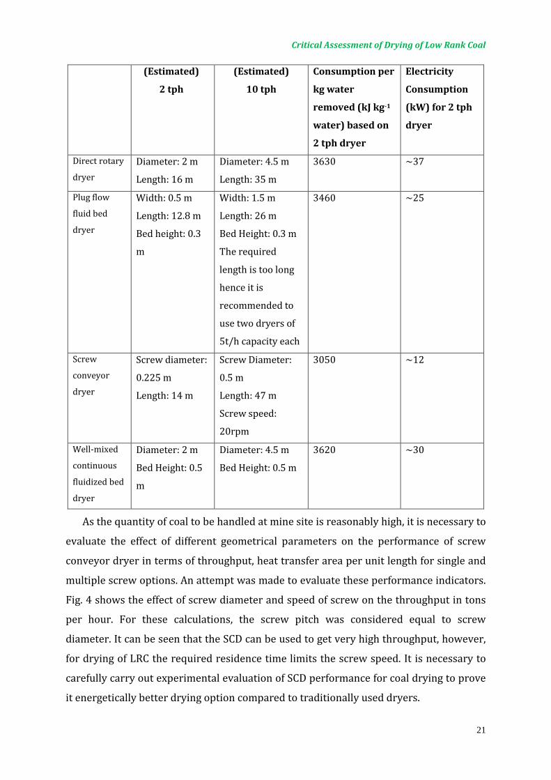
Table 2 shows the comparison based on the estimated size of each dryer type, energy
used per kilogram of water removed and the mechanical power required, which includes
fan power etc. It can be seen that theoretically screw conveyor dryer has less energy
consumption compared to other dryer. This is because of the higher heat transfer
coefficient and the higher heat transfer area to per unit length of the dryer. The
mechanical energy consumption is also low as major use is driving the screw and
material, while the quantity of gas used is low. Although the difference in the power use
is not considerable compared to other dryers, the installation cost for screw conveyor
dryers is comparably low. Screw conveyor dryers have additional advantages such as
indirect heating and use of vacuum which reduces the chances of fire hazards. However,
for higher throughput the required length of the screw conveyor is very high, hence it is
recommended to vary the screw pitch and the flight design to get higher heat transfer
area per unit length which can result in to reduced length of the dryer. Another way to
increase the heat transfer area in a unit length is to have multiple screws which can
enhance the throughput as well. It is essential to determine heat transfer area per unit
length for different arrangement of screws and the flights design.
For dryers using low air flow (or gas flow) it is obvious that the cost of dust control is
lower. Application of vacuum costs electrical power but eliminates fire hazard. Thus a
comparison based only on a few parameters is at best a partial one but gives an idea
about the relative expected performance in the absence of hard data and testing. The
figures given in Table 2 are therefore only preliminary estimates that need to be
validated in future. It was not possible to obtain cost data from vendors of such
equipment so a key piece of information is still lacking. Note that the aforementioned
study is at best an estimate since dryer performance does not depend solely on dryer
type but also on its operation and whether it is optimal.
Table 2: Sizing of different dryer options for drying 2 tph and 10 tph of coal
Dryer type Dimensions Dimensions Energy Other
Critical Assessment of Drying of Low Rank Coal
21
(Estimated)
2 tph
(Estimated)
10 tph
Consumption per
kg water
removed (kJ kg-1
water) based on
2 tph dryer
Electricity
Consumption
(kW) for 2 tph
dryer
Direct rotary
dryer
Diameter: 2 m
Length: 16 m
Diameter: 4.5 m
Length: 35 m
3630 ~37
Plug flow
fluid bed
dryer
Width: 0.5 m
Length: 12.8 m
Bed height: 0.3
m
Width: 1.5 m
Length: 26 m
Bed Height: 0.3 m
The required
length is too long
hence it is
recommended to
use two dryers of
5t/h capacity each
3460 ~25
Screw
conveyor
dryer
Screw diameter:
0.225 m
Length: 14 m
Screw Diameter:
0.5 m
Length: 47 m
Screw speed:
20rpm
3050 ~12
Well-mixed
continuous
fluidized bed
dryer
Diameter: 2 m
Bed Height: 0.5
m
Diameter: 4.5 m
Bed Height: 0.5 m
3620 ~30
As the quantity of coal to be handled at mine site is reasonably high, it is necessary to
evaluate the effect of different geometrical parameters on the performance of screw
conveyor dryer in terms of throughput, heat transfer area per unit length for single and
multiple screw options. An attempt was made to evaluate these performance indicators.
Fig. 4 shows the effect of screw diameter and speed of screw on the throughput in tons
per hour. For these calculations, the screw pitch was considered equal to screw
diameter. It can be seen that the SCD can be used to get very high throughput, however,
for drying of LRC the required residence time limits the screw speed. It is necessary to
carefully carry out experimental evaluation of SCD performance for coal drying to prove
it energetically better drying option compared to traditionally used dryers.

Critical Assessment of Drying of Low Rank Coal
22
Fig. 4. Effect of geometrical parameters on coal throughput (P = DSC; t = 0.006m; Dsh =
0.25DSC; )
10. SUSTAINABILITY IN LRC DRYING
Sustainability is very important in every field when a new idea is proposed. Life cycle
assessment of any process is also a part of developing a sustainable technique. This
mainly involves measuring the environmental impact of the process essentially in terms
of the carbon foot prints and energy utilized. It is necessary to develop sustainable
technique for drying of LRC. The drying process for LRC can be made sustainable only if
the cost for removal of moisture is moderately less that the returns from dried LRC. The
energy used for drying cannot be more than the added energy value to the coal. The best
way to make this sustainable is to use maximum renewable energy, where ever
possible.[28] However, this is not always feasible as these energy sources are time
varying and most of the times unpredictable. But, the right choice of a dryer/drying
system, the drying medium and careful design of dryer linked with use of waste heat and
renewable source of energy can result in a cost-effective and hence sustainable drying
process. In the present work the comparison is made based on the energy used in
different drying process and the added energy value to LRC. Fig. 5 explains the options
to develop cost-effective and sustainable drying system for LRC.
0
20
40
60
80
100
120
140
0.1 0.15 0.2 0.25 0.3 0.4 0.5
Thro
ughp
ut (T
PH)
Screw Diameter (m)
40 RPM
30 RPM
20 RPM
10 RPM

Critical Assessment of Drying of Low Rank Coal
23
Fig. 5. Steps to develop innovative and sustainable drying system for LRC
CLOSING REMARKS
It is now clear that the world will depend on clean coal technologies at least over the
next three to four decades before alternative energy sources and energy conservation
measures will reduce dependence on this key fossil fuel source that is widely distributed
globally unlike oil and gas. Drying will be an essential intermediate stage in coal-based
power generation regardless the route taken e.g. direct combustion, gasification or
liquefaction. Since energy will be consumed in upgrading coal via drying the most
effective coal drying technology must be energy-efficient, safe, cost-effective and with
minimal carbon footprint. Numerous attempts have been reported in the literature using
Drying of Low Rank Coal
Drying at Mine Site Drying at Plant Site
Drying during conveying from Mine site to Barge port
Use of Renewable sources of energy
Use of coal Mine Methane
Use of plant waste heat
Use of flue gases from the plant
Use of Renewable sources of energy
Experimentation and use of the advanced computational tools
Cost-effective and sustainable drying technology for LRC
Recovering heat from dryer exhaust / Recycle of exhaust
drying gas
Critical Assessment of Drying of Low Rank Coal
24
traditional dryers and for very large scale power plant operations using superheated
steam as the drying medium. Detailed studies are needed to evaluate various
technologies on a uniform basis although optimal dryers will necessarily be different for
different geographical locations; post-processing operation involved, whether dryer is at
mine mouth or near power plant etc. Mujumdar[35-37] has discussed various innovative
drying technologies and even the potential to intensify innovation via mathematical
modeling.[39] Some of these need to be examined for LRC drying. Hybrid drying
technologies, admixture with various types of biomass and waste sludge as sources of
thermal heat input for drying, use of renewable energy sources like solar and wind
energy at mine sites, ambient air drying during long haul conveying of coal to barges or
bulk carriers and even dehydration during transport by ships or freight trains etc are all
potential opportunities that have yet to be explored carefully. Finally, any drying
solution to be successful it must be sustainable e.g. using more energy for drying LRC is
not a sustainable operation if the upgrading results in a higher calorific value coal but
with net loss of energy. Dryers for biomass and mixtures of biomass with coal are also
relevant for drying of LRCs. Currently more R&D attention is being paid to biomass and
sludge drying; the readers should refer to that literature as well (e.g. Pang and
Mujumdar[32]). Many challenges lie ahead in coal upgrading for the energy-hungry world
with increasing population and depleting energy resources. Use of alternative energy
sources to cut down use of coal in coal drying operations is worthwhile to reduce carbon
foot print of the coal drying operation.
NOMENCLATURE
A Area for heat transfer (m2)
c Clearance (m)
Dsc Screw diameter (m)
Dsh Shaft diameter (m)
FB Bearing factor
FD Screw geometry factor
FF Flight factor
FM Material factor
Critical Assessment of Drying of Low Rank Coal
25
FP Paddle factor
Fv Volumetric throughput (m3 h-1)
L Length of the screw (m)
n Screw speed (rpm)
p Pitch (m)
Pmaterial Power required to drive material (W)
Pscrew Power required to drive empty screw (W)
Qtotal Total heat flux required (W)
U Overall heat transfer coefficient (Wm-1K-1)
Greek Letters
λ Degree of fullness (-)
ρs Solid density (kg m-3)
REFERENCES
1. Karthikeyan, M.; Zhonghua, W.; Mujumdar, A.S. Low-rank coal drying technologies -
current status and new developments. Drying Technology 2009, 27(3), 403-405.
2. Pikon, J.; Mujumdar, A.S. Drying of coal. In Handbook of industrial drying, 3rd Ed.;
Mujumdar, A.S., Ed.; CRC Press; Boca Raton, Florida, 2006, 993-1016.
3. Thielemann, T.; Schmidt, S.; Gerling, J.P. Lignite and hard coal: Energy suppliers for
world needs until the year 2100-An outlook. International Journal of Coal Geology
2007, 72, 1-14.
4. Nicholls, T. Coal: Explained. In How the energy industry works: An insiders' guide,
Silverstone Communications Ltd., London, UK, 2009, 111-112.
5. Katalambula, H.; Gupta, R. Low-grade coals: A review of some prospective upgrading
technologies. Energy & Fuels 2009, 23, 3392–3405.
6. Wilson, W.J.; Walsh, D.; Irvin, W. Overview of low rank coal drying. Coal Preparation
1997, 18, 1-15.
7. Li, C.Z. Advances in the science of Victorian brown coal. Elsevier Science, 2004.
8. Lucarelli, B. Benefits of "Drying" Indonesian low rank coals. Cleaner Coal Workshop,
Vietnam, August 19-21, 2008.
9. Karthikeyan, M.; Kuma, J.V.M.; C.S. Hoe; Ngo, D.L.Y. Factors affecting quality of dried
low-rank coals, Drying Technology 2007, 25(10), 1601-1611.
Critical Assessment of Drying of Low Rank Coal
26
10. Karthikeyan, M. Minimization of moisture readsorption in dried coal samples, Drying
Technology 2008, 26(7), 948-955.
11. Mujumdar, A.S. Handbook of Industrial Drying, 3rd Ed; CRC Press: Boca Raton, FL.
2006.
12. Hatzilyberis, K.S.; Androutsopoulos, G.P.; Salmas, C.E. Indirect thermal drying of
lignite: Design aspects of a rotary dryer. Drying Technology 2000, 18(9), 2009-2049.
13. Clayton, S.A.; Desai, D.; Hadley, A.F.A. Drying of brown coal using a superheated
steam rotary dryer. Proceedings of the 5th Asia-Pacific Drying Conference, 13–15
August, Hong Kong 2007; 179–184.
14. Mujumdar, A.S. Superheated steam drying: principles practice and potential for use of
electricity; Canadian electrical association, Montreal, Quebec, Canada, 1990. Report
No. 817, U 671.
15. Bongers, G.D.; Jackson, W.R.; Woskoboenko, F. Pressurized steam drying of
Australians low rank coals part I. Equilibrium moisture contents. Fuel Processing
Technology 1998, 57, 41-54.
16. Suwono, A.; Hamdani, U. Upgrading the Indonesia’s low rank coal by superheated
steam drying with tar coating process ad its application for preparation of CWM. Coal
Preparation 1991, 21, 149-159.
17. Ellman, R.C.; Belter, J.W.; Dockter, L. Adapting a pulse-jet combustion system to
entrained drying of lignite. Fifth International Coal Preparation Congress, October 3–
7, Pittsburgh, PA 1966; 463–476.
18. Chen, Z., Wu, W.; Agarwal, P. K. Steam-drying of coal. Part 1. Modeling the behavior of
a single particle. Fuel 2000, 79(8), 961-974.
19. Chen, Z.; Agarwal, P. K.; Agnew, J.B. Steam drying of coal. Part 2. Modeling the
operation of a fluidized bed drying unit. Fuel 2001, 80(2), 209-223.
20. Klutz, H.J.; Moser, C.; Block, D. WTA Fine Grain Drying—Module for Lignite-Fired
Power Plants of the Future; 2006. Report PT 11, VGB Power Tech. Essen.
21. Lechner, S.; Höhne, O.; Krautz, H.J. Pressurized steam fluidized bed drying (PSFBD) of
lignite: constructional and process optimization at the BTU test facility and
experimental results. Proceedings of the XII Polish Drying Symposium, Lodz, Poland,
September 14-16, 2009; 734-741.
Critical Assessment of Drying of Low Rank Coal
27
22. Hoehne, O.; Lechner, S.; Schreiber, M.; Krautz, H.J. Drying of lignite in a pressurized
steam fluidized bed – Theory and Experimentation. Drying Technology 2010, 28(1-
3), 5-19.
23. Waje, S.S.; Thorat, B.N.; Mujumdar, A.S. An experimental study of the thermal
performance of a screw conveyor dryer. Drying Technology 2006, 24(3), 293-301.
24. Graham, J. Microwave for coal quality improvement: The drycoal project. Report on
drycoal project, 2008.
25. Choicharoen, K.; Devahastin, S.; Soponronnarit, S. Performance and energy
consumption of an impinging stream dryer for high-moisture particulate materials.
Drying Technology 2010, 28(1-3), 20-29.
26. Li, Z.; Su, W.; Wu, Z.; Wang, R.; Mujumdar, A.S. Investigation of flow behaviors and
bubble characteristics of a pulse fluidized bed via CFD modeling. Drying Technology
2010, 28(1-3), 78-93.
27. Baker, C.G.J. Energy efficient dryer operation – an update on developments, Drying
Technology 2005, 23(9-11), 2071 – 2087.
28. Kudra, T.; Platon, R.; Navarri, P. Excel-based tool to analyze the energy performance
of convective dryers. Drying Technology 2009, 27(10-12), 1302-1308.
29. Levy, A. Use of coal drying to produce water consumed in pulverized coal power plants.
Quarterly report for the period July 1, 2005 to September 30, 2005. Energy Research
Center, Bethlehem.
30. Bibler, C.J.; Marshall, J.S.; Pilcher, R.C. Status of worldwide coal mine methane
emissions and use. International Journal of Coal Geology 1998, 35(1-4), 283-310.
31. Carothers, F.P.; Schultz, H.L.; Talkington, C.C. Mitigation of methane emissions from
coal mine ventilation air: An update. Available at
http://www.irgltd.com/Resources/Publications/US/2003-2005 Mitigation of
Methane Emissions from Coal Mine Ventilation Air Update.pdf.
32. Pang, S.; Mujumdar, A.S. Drying of woody biomass for bioenergy: drying technologies
and optimization for an integrated bioenergy plant. Drying Technology 2010, 28(5),
690-701.
33. Leon, A.M.; Kumar, S. Design and performance evaluation of a solar-assisted biomass
drying system with thermal storage. Drying Technology 2008, 26(7), 936-947.
34. Xu, Q.; Pang, S. Mathematical modeling of rotary drying of woody biomass. Drying
Technology 2008, 26(11), 1344-1350.

Critical Assessment of Drying of Low Rank Coal
28
35. Kanda, H.; Makino, H.; Miyahara, M. Energy-saving drying technology for porous
media using liquefied DME gas. Adsorption 2008, 14, 467-473.
36. Kanda, H.; Makino, H. Energy-efficient coal dewatering using liquefied dimethyl
ether. Fuel 2010, 89, 2104-2109.
37. Mujumdar, A.S. Drying technologies of the future. Drying Technology 1991, 9(2),
325-347.
38. Mujumdar, A.S. Innovation in drying. Drying Technology 1996, 14(6), 1459 – 1475.
39. Mujumdar A.S. Research and Development in drying: Recent trends and future
prospects. Drying Technology 2004, 22(1-2), 1-26.
40. Jamaleddine, T.J.; Ray, M.B. Application of computational fluid dynamics for
simulation of drying processes: A review. Drying Technology 2010, 28(1-3), 120-
154.
41. Mujumdar, A.S.; Wu, Z. Thermal drying technologies-Cost-effective innovation aided
by mathematical modeling approach. Drying Technology 2008, 26, 146-154.
42. Perre, P. Meshpore: A software able to apply image based meshing techniques to
anisotropic and heterogeneous porous media. Drying Technology 2005, 23(9-11),
1993-2006.
43. Gong, Z.X.; Mujumdar A.S. Simulation of drying nonaqueous systems – An application
of Simprosys software. Drying Technology 2010, 28(1-3), 111-115.
44. Zaidi, S.A.H. Ultrasonically enhanced coal desulphurization. Fuel Processing
Technology 1993, 33, 95-100.
45. Van't Land, C.M. Industrial drying equipment: Selection and application, Marcel
Dekker, Inc., New York. 1991.
46. Markowski, A.S.; Mujumdar, A.S. Safety aspects of industrial dryers. In Handbook of
industrial drying, 3rd Ed.; Mujumdar, A.S., Ed.; CRC Press; Boca Raton, Florida, 2006,
1133-1160.
47. Waje, S.S.; Mujumdar, A.S.; Thorat, B.N. Screw conveyor dryer: Process and
equipment design. Drying Technology 2007, 25(1), 241-247.

Review of Patents on Drying of Low Rank Coal
H.B. Osman, S.V. Jangam and A.S. Mujumdar
Minerals, Metals and Materials technology Centre, National university of Singapore
Contents
1. INTRODUCTION ..................................................................................................................................... 31
2. DRYING OF LOW-RANK COAL (LRC) ............................................................................................ 31
2.1. Benefits of Drying LRC ...................................................................................................................................................... 31 2.2. Challenges in Drying LRC ................................................................................................................................................. 32
3. CLASSIFICATION AND SELECTION OF DRYER ........................................................................ 32
4. RECENT PATENTS ON COAL DRYING .......................................................................................... 33
4.1. Rotary Drying ........................................................................................................................................................................ 33 4.2. Fluidized Bed Dryers (FBD) ............................................................................................................................................ 36 4.3. Superheated Steam Drying .............................................................................................................................................. 39 4.4. Microwave Drying ............................................................................................................................................................... 40 4.5. Microwave-assisted Drying ............................................................................................................................................. 43 4.6. Screw Conveyor Dryer (SCD) ......................................................................................................................................... 44 4.7. Solvent Displacement ........................................................................................................................................................ 46 4.8. Dewatering Techniques .................................................................................................................................................... 47 4.9. Integrated Drying of Coal Feedstock ........................................................................................................................... 47
5. FUTURE TRENDS ................................................................................................................................... 48

Review of Patents on Drying of Low Rank Coal
31
1. INTRODUCTION
Selecting a suitable dryer for specific application is a challenging task, considering that
numerous variation of dryers exist in the market. More often than not, no two dryers are exactly
the same, and were designed for very specific function. Therefore, the choice of dryer must take
into account numerous factors so as to maximize the return on investment. Mujumdar[1] have
presented a comprehensive checklist for dryer selection. Because this article focuses on the
drying coal, albeit the special emphasis on low-rank coal (LRC), we will review patents filed
within the last 25 years in the US, Europe and Japan. Although the primary interest is towards
patents that are relevant to drying of coal, patents which do not explicitly specify coal as its
target subject, but which have potential for coal applications, were also considered.
2. DRYING OF LOW-RANK COAL (LRC)
2.1. Benefits of Drying LRC
Low-rank coal (LRC) such as lignite (brown coal) and sub-bituminous coal account for about
50% of the world coal reserve. However, their applications are limited due to their low heating
value and spontaneous combustion property. Low-rank coal contains very high amount of
moisture, rendering low energy output and low fuel efficiency compared to higher rank coals.
For example, moisture content in Victorian brown coal can be as high as 66%[2], whereas Silesian
anthracite may contain as little as 0.6% moisture[3]. Evaporation of coal water during the
combustion of LRC reduces the net energy output and efficiency of plant, and increases stack gas
flow. Bulk transportation of LRC is expensive due to the presence of significant amount of water;
its self-ignition property increases difficulty in handling and storage due to safety reasons; and
its low friability render blending operations and pneumatic transportation less effective.
However, LRC have certain advantages over black coal. Among the advantages are: low
mining cost, high reactivity, high amount of volatiles and low pollution-forming impurities such
as sulfur, nitrogen and heavy metals[4]. High moisture content makes drying LRC an essential
component in any upgrading or utilization processes. For example, drying of LRC can result in
major savings in transportation costs. According to Lucarelli[5], a coal producer can save
$0.19/GJ of energy on storage and handling and transportation costs if LRC is dried from 35% to
just 25% moisture content, while, the savings on logistics costs could be as high as $7 million per
year for a 600 MW plant. Increased calorific value of dried LRC also warrants higher market
value. Other benefits include increased plant efficiency, lower transportation cost, reduced risk
of spontaneous combustion, lower GHG emissions through clean coal technologies (CCT), and
greater energy security.
Review of Patents on Drying of Low Rank Coal
32
2.2. Challenges in Drying LRC
LRC presents a fire hazard if measures are not taken to prevent the spontaneous combustion
of the material. One way of preventing unwanted ignition of coal during drying is by using a
drying medium that has low oxygen content such as superheated steam. However, utilizing
superheated steam involves enormous capital expenditure due to the cost associated with the
construction and running of the steam system. Another way of preventing spontaneous
combustion of coal is by employing indirect heat treatment using indirect dryers. Dried LRC are
also susceptible to self-ignition when exposed to excessive moisture; and this susceptibility
increases as particle size get smaller[6]. Hence, there is a need to properly store dried LRC for the
sake of safety, and also to minimize moisture re-adsorption so that drying is not perceived as a
wasteful use of energy. Various methods to minimize moisture re-adsorption exist, and have
been thoroughly discussed by Karthikeyan[6]. However, it remains to be seen if such methods are
cost-effective when massive amount of coal is involved.
Loss of volatile organic compounds (VOC) as a result of drying LRC at high temperatures is
another issue that must be addressed. The loss of useful volatile matter from LRC reduces its
calorific while at the same time increases the risk of fire from the combustion of VOCs. Drying at
lower temperature or by using slight vacuum environment can minimize the loss of VOCs.
However, these approaches result in lower rate of drying.
Cost involved in the drying of LRC is another important consideration. In the attempt to
upgrade a relatively low-value fuel, a comprehensive techno-economical study must have
already been carried out beforehand to ensure that the effective cost of producing dried LRC do
not exceed the market value of commercial coal with the same calorific value. Although
numerous commercial scale dryers exist, not all are suitable for drying LRC. Therefore, there is a
need for careful and systematic evaluation of dryer designs to maximize the efficiency, cost-
effectiveness, and safety of a drying equipment selected for LRC application.
3. CLASSIFICATION AND SELECTION OF DRYER
There are many ways to classify drying methods and processes. Dryers can be batch or
continuous type, or be grouped according to how heat is transferred to the wet material. Direct
drying involves the direct contact between the drying medium and the material (also known as
convective drying), whereas the steam tube dryer and the coal-in-tube dryer discussed
elsewhere in this article are examples of indirect dryers. Here, dryers are grouped according to
their physical design and the principle of operation. The reader is asked to refer to Mujumdar[1]
and Kudra[7] for more details. It is noteworthy that dryer selection is also affected by
geographical location, value of the product, safety considerations and scale of operation. Also,

Review of Patents on Drying of Low Rank Coal
33
the downstream processing and utilization can have important bearing on selection of the dryer
type. No universal recommendation can be made for dryer selection for any material.
4. RECENT PATENTS ON COAL DRYING
Coal is a broad classification of naturally occurring solid fuel that can be found below the
surface of the earth. They are classified according to rank: High-rank coals are anthracite and
bituminous coal, and low-rank coals are usually in the form of lignite or sub-bituminous coal.
The rank of coal reflects the degree of coalification of the material such that the higher-ranking
coals are highly coalified and vice versa. Generally, low-rank coals tend to contain high amount
of moisture whereas anthracites may contain as little as 1%, depending on the location from
which they are mined. Even so, nearly all coal, regardless of rank, will go through a drying stage
since freshly mined coals are usually washed to remove contaminants. Hence, we have
established that drying of coal one of the key processes in coal utilization. Because properties of
coals vary, careful consideration of the physical form of feed is critical in any dryer design. Also
the presence of sulfur and ash content can influence the needs of drying LRC.
In the following discussion we have classified different dryer types that appear in the patent
literature for ease of discussion and comparison. It is important to note that unlike the archival
literature, the patent literature does not provide scientific or engineering data or techno-
economic analysis. The patents may include claims that are not independently verified. A patent
can be nullified if it is challenged o the grounds that it provides in adequate data or is based on a
previously published work.
4.1. Rotary Drying
The rotary dryer consist of a large rotating cylindrical shell that is slightly tilted such that the
feed discharge end is lower than the feeding section. As the drying vessel rotates, feed material
progresses from the higher end of the vessel to its lower end, under the influence of gravity, and
lifting action provided by the circumferentially mounted flights. The periodic lifting and
showering of the material creates a curtain of particles through which hot gas flows. This
agitation leads to higher efficiencies, increase heat transfer rate, and reduces processing time
compared to stationary units. Thus, feed material is heated and dried as it progresses through
the dryer. Extensive study of flight design can be found in Revol et al.[8] and Krokida et al.[9] while
innovative flight designs can be found in several other patents. For example, Christensen[10]
disclosed passive rakes that have stirring, lifting, and breaking elements, while Butler[11] and
Dillman[12] described removable flights for altering flow patterns. All these internal elements can
help improve flow of the material in the vessel and also help enhance the heat and mass transfer

Review of Patents on Drying of Low Rank Coal
34
coefficients. The patents do not provide the necessary technical data, however. The effectiveness
of these various design changes is hard to assess and compare in concrete terms.
Depending on the feed properties, the drying gas can flow in the direction of feed
progression (parallel flow), or in opposite direction (counter-flow). Although counter-current
flow offers higher thermal efficiency, parallel flow is preferred for reasons of safety and product
quality, and especially for heat sensitive materials such as coal. Additionally, the method of heat
transfer between the feed material and the drying medium, whether direct, indirect, or both
indirect and direct (henceforth referred to as indirect-direct) is another factor to consider.
In direct dryers, the wet material is in direct contact with the drying medium. When drying
low-rank coal and other combustible material, gas should be relatively free of oxygen. In this
case, superheated steam or inert gas (e.g. Nitrogen) can be used as drying medium. Example of
patents related to this class of rotary dryers, can be found in Yamato[13], Livingston[14], and Duske [15]. The Yamato design is unique in that it injects the drying air in the rolling bed that forms in
the lower half of the rotating cylinder; this is claimed to double the volumetric heat and mass
transfer rates thereby decreasing the size of the dryer by a factor of two. This is a tremendous
improvement.
In conventional rotary dryers, convective heat and mass transfer between drying gas and the
wet material occurs mostly during the showering of lifted particles since the rolling bed (dead
zone) only contribute around 5%[7]. These limitations are circumvented in the Yamato dryer, in
which drying gas is blown through a rolling bed of wet material, through a plurality of tubes
branching off from a central tube. Except for the said tubes, and a more compact vessel and
ancillary equipments (blower, cyclone, etc), the Yamato dryer is physically similar to
conventional rotary dryers. Kudra and Mujumdar[7] reported that more intimate gas-to-particle
contact in the Yamato dryer result in high heat transfer and drying rates, while at the same time
maintain relatively low particle attrition compared to conventional rotary dryers.
Akira et al.[16] have disclosed an invention that falls under the category of indirect rotary
dryer. This patent describes a multiplicity of coal-carrying tubes housed within an inclined
rotary vessel where superheated steam flows without entering the tubes. Wet feed enters the
inclined tubes under the influence of gravity, and is distributed among the tubes as the vessel
rotates. Helical wire inside each tube serves to regulate the flow of coal being dried and ensure
sufficient resident time. The use of indirect heating and superheated steam significantly reduce
fire risk. Further, dust formation is greatly reduced since product attrition due to the tumbling
action is not as pronounced as compared to conventional rotary dryers.
Alexander et al.[17] have disclosed an example for indirect-direct dryer, in a patent that
described a cylindrical rotary drum enclosed in a furnace-like cavity with integrated burners.

Review of Patents on Drying of Low Rank Coal
35
Two sections make up the drum--heater section (located upstream, near material infeed) made
of aluminum and extending for approximately one-third of the length of the drying vessel, and a
burner section (located downstream, near product discharge point) made of stainless steel and
extending the remaining length of the drying vessel. This dryer design is somewhat different
from other rotary dryers in its class in two major ways:
First, heating of the wet product is achieved both directly and indirectly—indirect heating is
achieved by using hot combustion gas to heat the drum sections from their exterior surfaces,
while direct heating is achieved by driving that same gas into the vessel from the proximate end
of the burner section.
Second, a multiplicity of stainless steel fins are mounted on the outer surface of the shell and
oriented such that fins on the pre-heater section (aluminum shell) serve to agitate the
surrounding air, while fins on the burner section (stainless steel shell) serve to move air
downstream and into the vessel. This arrangement not only facilitates the external heating of the
drum, but also produces hot gas stream that result in counter-flow direct heating of feed
material. The authors have not found such novel use for fins in other similar inventions.
Livingston et al.[14] patented a triple-pass rotary dryer which consist of three concentric
hollow cylinders that rotate at the same speed, and are in communication with each other
through apertures near the end of the cylinders. The wet material move through the outermost
shell, is forced in the reverse direction through the first inner tube, then pass in the original
direction in the second inner tube, and finally discharged. Although the multi-pass system aims
to provide sufficient gas-particle mixing while keeping the cylinder relatively short, such system
is expected to be expensive to build, operate, and maintain due to their complex internal
structure.
In response to the limitations of a multi-pass system that Livingston disclosed, Duske[15]
described a single-pass rotary dryer that also aim to provide sufficient resident time without
extending the length of the vessel. The inclusion of a perforated core and lifters serve to impede
the flow of the material and provide a showering effect to improve heat transfer rate and
thermal efficiency. However, it is not known if improvement in heat transfer rate is significant
enough to offset the capital cost of the highly complex dryer.
More recently, Livingston[18] disclosed a novel multi-pass rotary dryer design (also called the
rotary impinging stream dryer) that operates at lower temperature and gas velocity, with
increase in the residence time of the material to be dried. With reference to Fig. (1), the drying
air and wet particles enter from the gas inlet port and material inlet port respectively. Vanes in
the upstream region of the rotating vessel facilitate the mixing of gas and particle in preparation
for the pneumatic transport of particles through the vessel. As the gas-particle mixture

Review of Patents on Drying of Low Rank Coal
36
progresses downstream, it encounters two drying sections, each comprising an upstream
turbulator and a downstream serpentine flow section. Mixing of the gas-particle mixture is
intensified as the gas-particle mixture flows through the turbulator, increasing heat transfer
rate. The serpentine flow section increases particle resident time while keeping the dryer
relatively compact. From the description of the design it appears that the rotation does not help
enhance the drying rate as it appears to behave more like a flash dryer with rotating wall. The
design is also too complex to be of commercial interest.
Fig (1). Rotary impinging stream dryer.
There is much technical literature to indicate that impinging streams can yield very high
transfer rates. However, while truly novel this patent recommends a design that is complex and
probably more expensive. Its cost-effectiveness needs to be proven independently in academic
laboratories both experimentally and via mathematical modeling. Indeed, this design and
variations thereof may be good research projects for academics.
4.2. Fluidized Bed Dryers (FBD)
Fluidized bed drying is ideal for a wide range of particulate or granular solids and has found
widespread usage in various industries including those dealing with chemicals, pharmaceutical
and biochemical, food and dairy products, and polymers. Excellent gas-particle contact in
fluidized bed dryers offer high heat and mass transfer rates, and high drying rate while
preventing the overheating of individual particles. Thermal efficiency is also high, and can be
increased further by heat exchangers immersed in the fluidized layer. Other advantages include,
smaller flow area, relatively lower capital and maintenance cost, and ease of control. However,
an FBD is not without its limitations. Among the major issues in fluidized bed drying are high
power consumption, increased gas handling requirements, high tendency to cause product
attrition, and low flexibility in terms of feed type that can be handled.
Fluidized bed dryers can compete successfully with more conventional dryer types (e.g.
rotary, tunnel, conveyor) in the drying of powders, granules, agglomerates, and pellets, with
particles averaging between 50 µm to 5000 µm. Both heat sensitive and non-heat sensitive
Review of Patents on Drying of Low Rank Coal
37
products can be dried using one or more of the FBD variants, among which, the most common
are: Batch FBD, Well-Mixed Continuous FBD (WMFBD), Plug-Flow FBD (PFFBD), Vibrated FBD
(VFBD), Mechanically-Agitated FBD, Centrifugal FBD, and Spouted Bed Dryers (SBD). Each
variant design has its strengths and weaknesses and their implementation is highly dependent
on feed and product requirements.
Stone[19] patented a circular vibratory FBD which feature two drying decks positioned one
above another in a drying vessel. He claimed that such design, when compared to similar-sized
single deck dryer, could process two times more material with only a slight increase in heat and
fan size. In effect, feed material go through two drying stages-in the upper deck, moist hot gas
emerging from the lower deck preheats the wet feed, causing some moisture to evaporate; after
sufficient time has elapsed, material on the upper deck is dropped to the lower deck where more
intensive drying take place.
Dunlop et al.[20] proposed several processes for drying coal, one of which is similar to the
Stone’s invention. In his patent, Dunlop et al. specified a multi-stage process in which coal will
pass through a two separate fluidized bed dryer. The upstream FBD will heat coal to 150–290 ºC
and the downstream FBD will further process coal at slightly higher temperature (around 50 ºC
higher than upstream). This process recirculates some of the exhaust gas by blending with
heated air.
However, the above FBD designs along with other conventional FBD possess several
limitations that can be listed as follows[21]:
• Need for high pressure drop requires high-pressure blower
• Spherical and cubic particles are more favorably fluidized
• Pressure drop and fluidization requirements restrict the size of fluidized bed vessel
• Particle size and distribution is highly restricted
• Prone to bed instability and reduced transfer characteristics due to aggregative
fluidization or channeling
To offset the negative effects of the last two constraints, Kudra et al.[22], described a pulsed
fluidized bed dryer (PFBD) that use two gas flow velocities such that the lower flow velocity
keeps the whole bed in an expanded state at all time, while the higher flow velocity fluidize
specific areas in sequentially pulsating manner such that a traveling wave of variable orientation
is formed in the bed. Fig. (2) shows the schematic of the above dryer. Particle entrainment due to
excessive gas flows, and the formation of dead zones, which result from non-uniform
fluidization, is common to both conventional and new FBD designs. A number of studies have

Review of Patents on Drying of Low Rank Coal
38
shown that pulsed fluidization can improve the fluidization quality as it eliminates the problem
of channeling and slugging. Li et al.[23] reported that the pulsating fluidized beds result in
reduced bubble size and better gas-particle contact; and went further to conclude that pulsating
frequency of 40 Hz produce normal fluidization.
Fig. (2). Pulsed fluidized bed dryer.
Other variations of the fluidized bed dryer have also been patented. These include: plug flow
drying of coal in inclined fluid bed drying system by Chang et al.[24], vibrated fluid bed drying of
fine coal particles by Ladt[25], and spouted fluidized bed granulating and drying of slurry by
Legros et al.[26]. Vibrated beds with internal heat exchanges immersed in the bed yield high
thermal efficiency but are not common due to the need to keep the bed height modest to allow
vibration effect to appear throughout the bed.
Generally, vibrated FBD can provide a gentler fluidization and thus preferred for processing
the following kind of feed: (1) feed material with a large particle size distribution; (2) sluggish or
sticky materials; (3) temperature sensitive material; and (4) fragile materials.
Although numerous designs based on the fluid bed concept exist, more designs continue to
surface in fully disclosed patents. However, not all will find widespread implementation due
factors such as cost and scalability, but mostly the concern for reliability of new, untested
designs. The performance of fluidized beds, usually characterized by the quality of fluidization,
depends highly on the size and shape of the feed particles, which is apparent in coal drying. To
facilitate fluidization of bed, the most straightforward way is to grind and sieve raw coal before
feeding into the drying vessel. Fluidization quality can also be improved by employing
mechanical vibration, agitation or pulsating flow of fluidizing gas, as described above. Recent
literature shows that vibrated beds are more energy efficient relative to pneumatically fluidized
beds as very low air flow rates are needed according to requirements of heat and mass transfer
rather than by the need to fluidize the bed of particles. There is also a development from Poland
that uses pulsed fluid beds which behave similarly to the vibrated bed but need significant flow
Review of Patents on Drying of Low Rank Coal
39
rate of air and additional complexity due to the need to rapid fluctuation of the flow rate.
Periodic fluidization of the conventional fluid bed in which only a small part of the bed is
fluidized at any instant can also save energy but this intermittency leads to somewhat longer
drying times. Periodic local vibration of a plug flow fluid bed could also save energy but this has
not been reported in the literature yet. Immersion of heat exchanger surfaces in a vibrated bed is
another idea to increase energy efficiency. The need to keep the bed shallow does not permit
much space for immersed heat exchangers so this idea has limited usefulness. Note that low
aeration rates allow for smaller ductwork and smaller dust control equipment.
4.3. Superheated Steam Drying
Although the concept of drying using superheated steam was conceived more than a century
ago, serious interest in superheated steam drying (SHSD) was only felt recently. This surge in
interest is partly due to advancements in the food processing, timbre, and electricity generation
industries. Many benefits are associated with SHSD, among which are: reduced risk of
spontaneous combustion [27, 28], increased drying rates, reduction in dust emission, better energy
efficiency and improved grindability [29, 30, 31, 32].
Shaffer et al.[33], described a method of drying lignite (or other similar carbonaceous
materials) using superheated steam and a centrifuge. One of the example process begin by first
heating ground coal (15ºC, MC 34%) in hot water (95ºC), and placing the resultant coal (65ºC,
MC 40%) in a centrifuge to remove surface moisture. The coal (MC now 34%) then proceeds into
sealed processor where it is heated by superheated steam to 245ºC in a pressurized
environment. More steam is then injected into the vessel to increase the temperature to 260ºC at
a pressure of 34 atm, resulting in the loss of more coal moisture. After cool water is sprayed on
the coal batch, they are finally taken to the centrifuge again to remove any remaining surface
moisture. All in all, the whole process was reported to reduce aggregate moisture content of coal
from 34% to 8%. Based on the information that system can process 75,000 lb per batch, and that
time inside the processor at sustained pressure and temperature is 15 minutes, we estimate that
the system throughput is 150 tph at maximum.
Because fire hazard associated with spontaneous combustion of coal is completely
eliminated in superheated steam drying, target moisture content can be achieved in very short
time by using higher steam temperature. Pang and Pearson[34], and on separate occasion, Defo et
al.[35], performed experimental studies to investigate the application of the superheated steam
drying at ultra-high temperatures and results concluded that ultra-high temperature drying save
more energy while reducing drying time up to ten times.

Review of Patents on Drying of Low Rank Coal
40
Most applications that use SHSD are usually integrated with other processes to fully utilize
latent and sensible heat from steam through some form of heat recovery techniques. GEA [36]
reported that primary energy consumption of a SHSD without any heat recovery consumes
about 750 kWh/ton evaporated water. Between 70–90% of this energy can be recovered by
using generated steam in another process, or by using Mechanical Vapor Recompression
whereby at least 200 kWh of electricity can be produced per ton of the said evaporated water.
Because SHSD involve very high capital cost, this technique is more economically viable for
adoption in large-scale power plants, or processes like WTA. In principle, any dryer can be
converted into a SHSD. SHS used in conjunction with flash dryers, fluidized bed dryers, spray
dryers, impinging jets and stream dryers, conveyor dryers, agitated bed dryers, and rotary
dryers have been successfully tested at pilot scale, with some products even commercialized.
Table 1 compares selected aspects of conventional and SHS dryers. The high capital cost and
complexity of SHSD has limited its commercial exploitation. When the energy costs rise steeply it
is likely to see significant market penetration.
Table 1. Economic comparison of conventional and SHS dryers.
(Source: SPE Dieffenbacher Group) Conventional SHS Capacity (kg o.d./h) 15,000 15,000 Air/steam flow (kg/h)
335,000 241,000
Fan volume (m3/h) 415,000 290,000 Motor (kW) 900 630 Heat demand (MW) 15.5 9 Heat recovery (MW) 0 5.5 Capital cost (Euro) 1,350,000 2,850,000 Energy cost (Euro) w/o heat recovery 2,900,000 1,400,000 w/ heat recovery - 560,000
4.4. Microwave Drying
There are extensive reviews in the archival literature on various aspects of microwave
drying and dryers. Several handbooks also cover the basic principles and major applications in
diverse industries[37, 38, 39, 47]. In view of their potential for application in various industries it is
not surprising that many patents have been issued covering various aspects of MW drying. We
will not cover other industrial application areas, which include sintering of metals of ceramics,
thawing of meats etc. Here we will classify the patents issued in past 25 years in the US and
Europe and provide additional details of ones that we believe are innovative and of special
interest.
Tremendous interest in the utilization of microwave (MW) in drying applications is evident
from the number of patents filed (more than 1500) for MW-related dryers in the past two
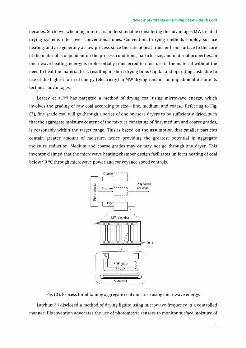
Review of Patents on Drying of Low Rank Coal
41
decades. Such overwhelming interest is understandable considering the advantages MW-related
drying systems offer over conventional ones. Conventional drying methods employ surface
heating, and are generally a slow process since the rate of heat transfer from surface to the core
of the material is dependent on the process conditions, particle size, and material properties. In
microwave heating, energy is preferentially transferred to moisture in the material without the
need to heat the material first, resulting in short drying time. Capital and operating costs due to
use of the highest form of energy (electricity) in MW drying remains an impediment despite its
technical advantages.
Learey et al.[40] has patented a method of drying coal using microwave energy, which
involves the grading of raw coal according to size—fine, medium, and coarse. Referring to Fig.
(3), fine grade coal will go through a series of one or more dryers to be sufficiently dried, such
that the aggregate moisture content of the mixture consisting of fine, medium and coarse grades,
is reasonably within the target range. This is based on the assumption that smaller particles
contain greater amount of moisture, hence providing the greatest potential in aggregate
moisture reduction. Medium and coarse grades may or may not go through any dryer. This
inventor claimed that the microwave heating chamber design facilitates uniform heating of coal
below 90 ºC through microwave power and conveyance speed controls.
Fig. (3). Process for obtaining aggregate coal moisture using microwave energy.
Latchum[41] disclosed a method of drying lignite using microwave frequency in a controlled
manner. His invention advocates the use of photometric sensors to monitor surface moisture of

Review of Patents on Drying of Low Rank Coal
42
lignite as it move into the microwave chamber. A controller programmed to process input
signals from sensors, controls the microwave power delivered. Such arrangement ensures that
surface moisture is present throughout most of the drying period, and prevents product
breakage due to rapid withdrawal of water. In addition, overheating of product is avoided since
temperature is set below 105 ºC.
Consider an invention by Weinberg et al.[42], which described a more rigorous control
method that has the capability to selectively alter coal properties. At the start of the process,
information about the coal is gathered. This information includes location of origin, purpose of
usage (e.g. electricity generation, steel production), properties of product desired, tonnage,
handling procedures required (e.g. grinding, screening), and properties of raw coal samples. All
these information provide the system with fine control over the material being processed such
that, for example, a narrow range of calorific value (or moisture content) for a coal batch having
a distribution of sizes and properties is possible. Hence, designer coals not found in nature can
be produced by this method.
Drozd et al.[43] described a comprehensive coal processing and drying procedure similar to
Weinberg et al. In the said patent, information on the equipment used, part specifications, and
mathematical modeling of waveguide patterns has been disclosed.
In most microwave drying applications, the feed is usually not stationary. This is because
microwave heating is known to be uneven, and tend to form regions of underexposure and
overexposure, commonly referred to as cold-spots and hot spots respectively. By keeping the
material in constant motion relative to the MW-guides, a more even heating can be achieved.
This relative movement is usually achieved by placing the material on a rotating plate or
conveyor, and passing it under the MW-guides as described by Leary et al., Latchum, Weinberg et
al. and Drozd et al. in the preceding paragraphs. Physical movement of waveguides to achieve a
similar effect has also been proposed. However, the invention is not relevant for our purpose.
Hein et al.[44] proposed another method of conveyance, that is, by utilizing reciprocating ram
for moving sludge through the microwave chamber. However, the use of reciprocating ram for
this purpose may not be ideal, due to excessive vibration and noise. The multi-level feature of the
invention is a commendable feature since it serves to reduce the footprint of the system, without
compromising capacity and throughput. In a more recent invention, Hein et al.[45] illustrated how
the said chamber can also be inclined to facilitate the progression of more viscous sludge
material.
All the above inventions utilize microwave as a stand-alone dryer. However, other drying
systems can also benefit from the advantages of microwave heating by applying a microwave
system in three ways: As pre-dryer, booster dryer, or post-dryer. When used as pre-dryer,

Review of Patents on Drying of Low Rank Coal
43
internal moisture is quickly forced to the surface, facilitating the optimal operation of the
conventional dryer. In booster drying microwave energy is added as the drying rate begins to fall
off, thereby sustaining or even increasing drying rate. When used as a post-dryer, the microwave
system greatly improve drying efficiency of the conventional dryer since the last one third of
water is the most difficult to remove by the conventional dryer alone.
In addition to the advantages mentioned above, Yang et al.[46] reported that microwave
treatment of coal is capable of reducing its total sulfur content by as much as 78%. Thus,
microwave drying also produce clean coal with low-sulfur content. The reader is asked to refer
to Schiffmann[47], Zhang et al.[48], and Constant[49] for further discussion on MW-related drying.
Microwave-assisted freeze drying can reduce time by an order-of-magnitde. However, the
cost factors still limit its commercial acceptance on a large scale.
4.5. Microwave-assisted Drying
Although fluidized bed drying thoroughly mix and uniformly expose products to drying air,
there is increasing difficulty of moving internal product moisture to the particle surfaces where
it can be taken up and moved away during the falling rate period[50]. On the other hand,
microwave drying offers very short drying time, albeit lower product quality due to uneven
exposure and moisture stresses[51] Microwave-assisted fluidized bed drying overcome the above
limitations by providing rapid and uniform drying at high energy efficiency, at a smaller
footprint.
Smith[52] disclosed a fluidized bed dryer that is configured to work as a waveguide at
microwave energy frequencies with gas inlet and outlet ports for fluidizing gas entry and exit;
see Fig. (4). The ports are sized sufficiently smaller than the wavelength microwave to prevent
microwave leakage to the external environment. As with most microwave devices, not all
microwave energy produced is absorbed by the material. To prevent excess reflected wave from
damaging the microwave generator, water is circulated near the downstream end of the
waveguide to absorb the remaining microwave. There are several drawbacks of this design:
First, the design do not allow for reflection of wave. Hence, microwave energy can only
propagate in one direction, absorbed either by the material or by the circulating load (water) as
it propagates. Further, the material to be dried must be placed near the centre of the waveguide
where the TE-10 mode microwave field is maximal. Since, there is no material below the
membrane (distributor plate), the material not at all absorbs microwave energy propagating
below the membrane. Hence, Smith’s design does not facilitate efficient use of microwave
energy.
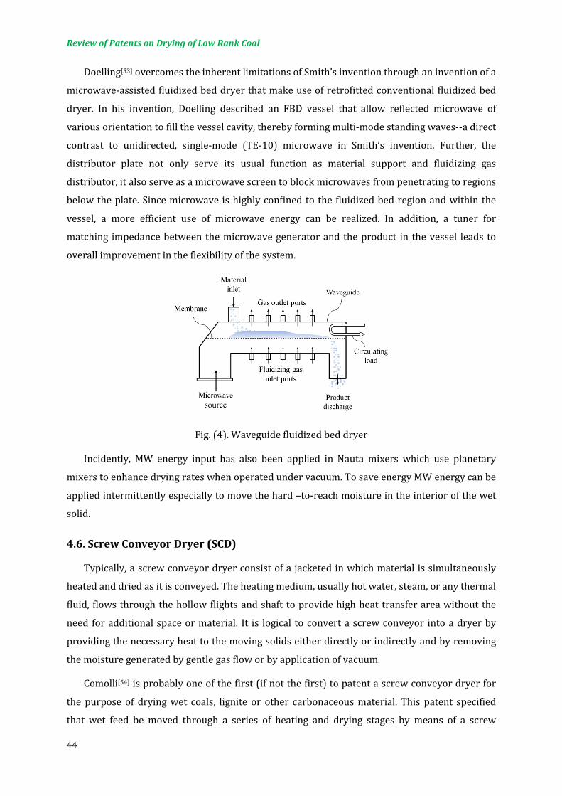
Review of Patents on Drying of Low Rank Coal
44
Doelling[53] overcomes the inherent limitations of Smith’s invention through an invention of a
microwave-assisted fluidized bed dryer that make use of retrofitted conventional fluidized bed
dryer. In his invention, Doelling described an FBD vessel that allow reflected microwave of
various orientation to fill the vessel cavity, thereby forming multi-mode standing waves--a direct
contrast to unidirected, single-mode (TE-10) microwave in Smith’s invention. Further, the
distributor plate not only serve its usual function as material support and fluidizing gas
distributor, it also serve as a microwave screen to block microwaves from penetrating to regions
below the plate. Since microwave is highly confined to the fluidized bed region and within the
vessel, a more efficient use of microwave energy can be realized. In addition, a tuner for
matching impedance between the microwave generator and the product in the vessel leads to
overall improvement in the flexibility of the system.
Fig. (4). Waveguide fluidized bed dryer
Incidently, MW energy input has also been applied in Nauta mixers which use planetary
mixers to enhance drying rates when operated under vacuum. To save energy MW energy can be
applied intermittently especially to move the hard –to-reach moisture in the interior of the wet
solid.
4.6. Screw Conveyor Dryer (SCD)
Typically, a screw conveyor dryer consist of a jacketed in which material is simultaneously
heated and dried as it is conveyed. The heating medium, usually hot water, steam, or any thermal
fluid, flows through the hollow flights and shaft to provide high heat transfer area without the
need for additional space or material. It is logical to convert a screw conveyor into a dryer by
providing the necessary heat to the moving solids either directly or indirectly and by removing
the moisture generated by gentle gas flow or by application of vacuum.
Comolli[54] is probably one of the first (if not the first) to patent a screw conveyor dryer for
the purpose of drying wet coals, lignite or other carbonaceous material. This patent specified
that wet feed be moved through a series of heating and drying stages by means of a screw

Review of Patents on Drying of Low Rank Coal
45
conveyor, while hot fluid circulate in the jacketed vessel. Each stage will subject coal to a
different temperature and pressure for optimal operation. Because heating of the feed material
is achieved indirectly through heated wall surfaces, contact with hot oxygen-containing gas is
avoided, thereby reducing fire risk when drying low-rank coal.
One of the benefits of a screw conveyor dryer with hollow flights and/or shaft is that it can
be used for indirect heating of the particles. As discussed in earlier sections, indirect heating is
highly desirable in the drying of coal. The safety is further enhanced if superheated steam or
nitrogen is used as the heating and/or drying medium. Moreover, SCD offers relatively high heat
transfer area-to-volume ratio compared to other dryers. Like other dryer types, SCD can also be
part of a multi-stage drying system. An example of such system is illustrated in Fig. (5) as
described by Okada[55].
Fig. (5). Multi-stage screw conveyor dryer
Maffet[56] described a mechanical dewatering method using two or more independently
rotated screw conveyors placed end-to-end within a porous cylindrical vessel. Each screw
conveyor consists of three sections, differentiated only by the diameter of the shaft, which get
progressively bigger with corresponding decrease in flight depth. As wet feed travel upstream
within a screw conveyor, water is squeezed out through the vessel wall that has evenly
distributed apertures sized between 12.5–250 µm.
Other innovations that are not directly applicable to coal drying, but may have potential for
further exploration and adaptation are listed in Table 2, with references to their corresponding
patent documents. There is little archival literature on SC drying at this time.

Review of Patents on Drying of Low Rank Coal
46
Table 2. References to screw conveyor devices for other applications
Reference Purpose Feature(s)
Gentry [62] Fracturing and washing of crushed lignite in scew conveyor.
Two sections screw—helical and notch section—permits higher rotational speed with some improvements in cleaning, less lignite loss, and reduced water requirements.
Costarelli [63] Drying of plastic materials through mechanical dewatering.
Water is expressed as screw conveyor compress solid near the tapered end of the housing. Blade breaks up compacted solid before discharge.
McCabe et al. [64]
Removing volatile components from a matrix (e.g. sludge, contaminated soil, etc)
Right-hand and left hand screw conveyors in parallel within housing where matrix is conveyed. Screw conveyors are heated by hot medium flowing through hollow shaft and flights.
Mentz [65] Drying of minerals and ores. Electric heating rings on outer surface of housing heat the drying chamber. Screw conveyor with cut and folded flights agitates conveyed solids.
Kiyohiro [66] Drying of waste with unpleasant odour.
SCD with heated by combustion gas flowing through jacket and hollow screw conveyor shaft. The jacket is a double tube combustion chamber, with H2 and O2 (ratio 2:1) as combustion gas.
Okada [60] Drying of resin pellet. Cascaded screw conveyor tubes, each jacketed by electric heating elements, offers multi-stage drying. Temperature and rotation speed of screw conveyors adjusted according to control data.
4.7. Solvent Displacement
Treatment of coal and coal fines in a variety of organic liquids as a means of enhancing the
stability of coal, while reducing energy requirements of coal water removal has been around
since 1926. One example is hot oil drying whereby raw coals are dried in hot oil after which most
of the oil is recovered. Oil that are absorbed into the coal pores supposedly result in greater
stability of the processed coal[62].
Apart from oil, drying of coal in other hydrocarbons has also been demonstrated with
success. For example, Murphy[63] described a two-fold improvement in drying time when
methanol was used as the drying liquid. Similarly, Cantu[64] described the use of alcohols with 1–
3 carbon atoms to facilitate the drying of coal.
Ground coal immersed in hot molten paraffin (104–163 ºC) was also shown to be another
effective dehydration method. Dean[65] showed that coal treated from such process display
dramatic increase in calorific value (originally 9,600 BTU/lb, upgraded up to 15,000 BTU/lb),
low final moisture content (around 3%), and inhibited rehydration due to paraffin displacement
of water in coal cavities.
Drying in organic solvent was found to be less energy intensive than conventional
evaporative means since the latent heat of vaporization of volatile solvents is significantly lower

Review of Patents on Drying of Low Rank Coal
47
than that of water[66]. Nevertheless, some thermal energy is still required for heating and solvent
recovery process. An attempt to further reduce this energy requirement is described by Yoon et
al.[67] through a process that claims to spontaneously displace surface moisture under sufficient
pressure, with little or no heating, and using a gas that can be converted into a non-polar,
hydrophobic liquid (e.g. butane). This concept is illustrated in Fig. (6).
Fig. (6). Dewatering of coal through solvent displacement of water
4.8. Dewatering Techniques
Bieldfeldt[68] described an invention which is essentially a Mechanical Thermal Expression
(MTE) system that incorporates a waste heat recovery component. In MTE, coal is both heated
and subjected to compression during which coal water is expressed or ‘squeezed out’. A more
recent variant of the MTE apparatus is disclosed in McIntosh et al.[69].
4.9. Integrated Drying of Coal Feedstock
Rao et al.[70] patented a drying system which is integrated into an Integrated Gasification
Combined Cycle (IGCC) plant. The drying component of this system uses high-pressure inert gas
(eg. Nitrogen) or high-pressure fuel gas produced from gasified coal, heated by the cooling
streams from the gasification units, to dry coal. Rao et al. showed that this system 6.2% more
power than conventional plant.
A similar concept is described in a separate invention by Bowling[71], in which preprocessing
of coal—including cleaning, drying, and grinding—and coal utilization in the form of electricity
generation, are part of an integrated process, where heat for drying may be bled from hot
combustion gas or generated steam; see Fig. (7).

Review of Patents on Drying of Low Rank Coal
48
Fig. (7). Integrated processing, drying, and utilization of coal
In addition to the process described by Bowling, Iijima et al.[72] disclosed a method to reduce
the spontaneous combustibility of low-rank coal in which the said material is rapidly heated to a
high temperature of up to 500 ºC, then rapidly cooled to 250 ºC, and finally aged in an
environment having less than 21% oxygen content and a temperature of less than 100 ºC for at
least one month. Despite greater thermal stability and lower equilibrium moisture content of
coal emerging from this process, the rapid heating to a high temperature and the extended
storage of processed low-rank coal in hot environment may increase the overall cost of the
process.
Integrated system such as the ones described in this section require that coal utilization
plant be close to the mine site to fully reap the benefits of such systems, since it make economic
sense to subject freshly mined low-rank coal to some form of heat treatment for moisture
removal in-situ.
5. FUTURE TRENDS
Conventional coal drying techniques pose a number of limitations. Firstly, complexity of teh
drying operation may translate into high capital and operating cost. For example, many drying
systems make use of a multiplicity of heat exchangers, cyclones and condensers. Second, many
systems, but especially systems that use steam or inert gas as drying medium, utilize large
boilers and compressors to achieve high operating pressures and temperatures. This arises from
the need to obtain high drying temperatures amidst high heat loss and poor heat exchange rates.
Finally, conventional coal drying techniques produce substantial amounts of coal fines due to
weakened coal structure caused by removal of water. Presence of excessive coal fines poses risk
to safety, pollutes the environment, demanding substantial resources for its suppression. It is
Review of Patents on Drying of Low Rank Coal
49
always important to calculate the bottom-line and the cost-effectiveness of any drying system
selected. Since drying is means of upgrading LRC so that it can be sold at a higher price, it is
important to calculate a priori the economic benefit accrued due to reduced transportation cost
and increased market value due to improved calorific value. Sulfur content and ash content of
the LRC have important consequence on the market value a well.
In general, there is no unique solution of LRC drying. Different dryers may be competitive
depending on scale, inlet/outlet moisture, ash content, value of fuel etc.
REFERENCES
1. Mujumdar AS. Classification and selection of industrial dryers, In Mujumdar’s
Practical Guide to Industrial Drying; Devahastin S, Ed.; Exergex Corp; Brossard,
Quebec, 2000.
2. Li CZ. Advances in the science of Victorian brown coal. Elsevier Science, 2004.
3. Bratek K, Bratek W, Gerus-Piasecka I, Jasienko S, Wilk P. Properties and structure of
different rank anthracites. Fuel 2002; 81: 97–108.
4. Wilson WJ, Walsh D, Irvin W. Overview of low rank coal drying. Coal Preparation
1997; 18: 1–15.
5. Lucarelli B. Benefits of drying Indonesian low rank coals. Cleaner Coal Workshop
2008; Vietnam; August 19–21.
6. Karthikeyan M. Minimization of moisture readsorption in dried coal samples. Drying
Technology 2008; 26: 948–955.
7. Kudra T, Mujumdar AS. Special drying technologies, In Advanced Drying
Technologies, 2nd Ed.; CRC Press; Boca Raton, Florida, 2009.
8. Revol D, Briens CL, Chabagno JM. The design of flights in rotary dryers. Powder
Technology 2001; 121: 230–238.
9. Krokida M, Marinos-Kuoris D, Mujumdar AS. Rotary drying, In Handbook of
industrial drying, 3rd Ed.; Mujumdar AS, Ed.; CRC Press; Boca Raton, Florida, 2006.
10. Christensen, J.S.: US5197204 (1993).
11. Butler, T.G.: US5515620 (1996).
12. Dillman, B.A.: US6726351 (2004).
13. Yamato, Y.: US5996245 (1999).
14. Livingston, J.T., Livingston, A.D.: US5555639 (1996).
15. Duske, W.P., Hogue, R.T., Koeslin. K.J.: US5746006 (1998).
Review of Patents on Drying of Low Rank Coal
50
16. Akira, N., Keiichi, K., Takeshi, W., Hominobu, O., Yoshiaki, H., Katsuhisa, M.:
EP0370144 (1988).
17. Alexander, D.J., Sindelar, R.A.: US5305533 (1994).
18. Livingston, A.: US7155841 (2007).
19. Stone, L.H.: US6829840 (2004).
20. Dunlop, D.D, Leyon C. K.: US20050188608 (2005).
21. Kudra T, Mujumdar AS. Drying in pulsed fluidized bed, In Advanced Drying
Technologies, 2nd Ed.; CRC Press; Boca Raton, Florida, 2009; pp. 77.
22. Kudra, T., Gawrzynski, Z., Glaser, R.: US5918569 (1999).
23. Li Z, Su W, Wu Z, Wang R, Mujumdar AS. Investigation of flow behaviors and bubble
characteristics of a pulse fluidized bed via CFD modeling. Drying Technology 2010;
28: 78-93.
24. Chang, Y.C., Merriam, N.W., Boysen, J.E.: US5087269 (1992).
25. Ladt, M.A.: US4444129 (1984).
26. Legros, R., Chaouki, J., Bi, X.T., Macchi, A., Ratnani, K.: US5913588 (1999).
27. Mujumdar, AS. Superheated Steam Drying: Principles Practice and Potential for Use
of Electricity; Canadian Electrical Association, Montreal, Quebec, Canada, 1990.
Report No. 817, U 671.
28. Faber EF, Heydenrych MD, Seppa RVI, Hicks RE. A technoeconomic compression of
air and steam drying. In Drying’ 86, Vol. 2; Mujumdar, A.S., Ed.; Hemisphere: New
York, 1986; 588–594.
29. Pikon J, Mujumdar AS. Drying of coal. In Handbook of industrial drying, 3rd Ed.;
Mujumdar AS, Ed.; CRC Press; Boca Raton, Florida, 2006; pp. 993-1016.
30. Wilson WJ, Walsh D, Irvin W. Overview of low rank coal drying. Coal Preparation
1997; 18: 1–15.
31. Bongers GD, Jackson WR, Woskoboenko F. Pressurized steam drying of Australians
low rank coals part I. Equilibrium moisture contents. Fuel Processing Technology
1998; 57: 41–54.
32. Suwono A, Hamdani U. Upgrading the Indonesia’s low rank coal by superheated
steam drying with tar coating process ad its application for preparation of CWM. Coal
Preparation 1991; 21: 149–159.
33. Shaffer, D.B.: US20100005710 (2010).

Review of Patents on Drying of Low Rank Coal
51
34. Pang S, Pearson H. Experimental investigation and practical application of
superheated steam drying technology for softwood timber. Drying Technology 2004;
22: 2079–2094.
35. Defo M, Fortin Y, Cloutier A. Modeling superheated steam vacuum drying of wood.
Drying Technology 2004; 22: 2231-2253.
36. GEA Barr-Rosin. Superheated steam drying. Retrieved Sep 5, 2010 form
http://www.barr-rosin.com/products/super-heated-steam-drying.asp.
37. Fu YC. Fundamentals and industrial applications of microwave and radio frequency
in food processing. In Food Processing: Principles and Applications; Smith JS, Hui YH,
Ed.; Wiley-Blackwell 2004.
38. Jones PL, Rowley AT. Diaelectric dryers. In Industrial Drying of Food; Baker CGJ, Ed.;
Springer 1997.
39. Ishii TK. Industrial applications of microwaves. In Handbook of Microwave
Technology, Volume 2, Applications; Ishii TK Ed.; Academic Press 1995.
40. Leary, T.R., Drozd, J.M.: US7666235 (2010).
41. Latchum Jr, J.W.: US4567340 (1986).
42. Weinberg, J.L., Ginther, N.E., Aten, J.A., Wang, R.T.: US20050160667 (2005).
43. Drozd, J.M., Druga, M.C., Lawson, S.L., Lang, F.C., Bullis, H.L.: US20090272028 (2009).
44. Hein, W., Granger, B.: US20050082283 (2005).
45. Hein, W., Granger, B.: US20080282573 (2008).
46. Yang JK, Wu YM. Relation between dielectric property and desulphurization of coal
by microwaves, Fuel 1987; 66: 1745–1747.
47. Schiffmann RF. Microwave and diaelectric heating. In Handbook of Industrial Drying,
Third ed.; Mujumdar AS Ed.; CRC Press: Boca Raton, FL, 2006.
48. Zhang M, Tang J, Mujumdar AS, Wang S. Trends in microwave-related drying of fruits
and vegetables. Trends in food science and technology 2006; 17: 524–534.
49. Constant T, Moyne C, Perré P. Drying with internal heat generation: Theoretical
aspects and application to microwave heating. AIChE Journal 1996; 42: 359–368.
50. Chen, G, Wang W, Mujumdar AS. Theoretical study of microwave heating patterns on
batch fluidized bed drying of porous materials Chem Eng Sci 2001; 56: 6823–6835.
51. Abbasi Souraki B, Andrés A, Mowla D. Mathematical modeling of microwave-assisted
inert medium fluidized bed drying of cylindrical carrot samples. Chem Eng and
Processing: Process Intensification 2008; 48: 296–305.

Review of Patents on Drying of Low Rank Coal
52
52. Smith F.J.: US3528179 (1970).
53. Doelling, M.K.: US4967486 (1990).
54. Comolli, A.G.: US4249909 (1981).
55. Okada, K.: EP1553369 (2005).
56. Maffet, V.: US4380496 (1983).
57. Gentry, C.C.: US4448678 (1984).
58. Costarelli, E.: US4520724 (1985).
59. McCabe, M.M., Dowd, B.S.: US5216821 (1993).
60. Mentz, J.W.: US5531034 (1996).
61. Kiyohiro, A.: JP2001165572 (2001).
62. Pikon J, Mujumdar AS. Drying of Coal. In Handbook of Industrial Drying, Third ed.
Mujumdar AS Ed.; CRC Press; Boca Raton, FL, 2006; pp 1013.
63. Murphy, C.L.: US4014104 (1977).
64. Cantu, T.S., Williams, M.C.: US4498246 (1985).
65. Dean, M.W.: US5815946 (1998).
66. Kudra T, Mujumdar AS. Displacement drying. In Advanced Drying Technologies,
Second ed. CRC Press; Boca Raton, FL, 2009.
67. Yoon, R., Luttrell, G.H.: US5458786 (1995).
68. Bielfeldt, F.: US5862746 (1999).
69. McIntosh, J.M., Huynh, D.Q.: US7383766 (2008).
70. Rao, A.D., Goodland, D.C.: EP0839267 (1995).
71. Bowling, C.M.: US5137539 (1992).
72. Iilima, M., Taoda, K.: US6068671 (2000)..

Simprosys for Energy Evaluation of Coal Drying Flowsheet
S.V. Jangam1, Z.X. Gong2 and A.S. Mujumdar1
1Minerals, Metals and Materials technology Centre, National university of Singapore
2Simprotek Corporations, 7375 Rollingdell Dr., Suite 41, Cupertino, California, USA
Contents
1. INTRODUCTION ...................................................................................................................................... 55
2. BACKGROUND AND ABOUT SIMPROSYS ................................................................................... 56
3. COAL DRYING .......................................................................................................................................... 56
3.1. Different ways to improve energy efficiency ..................................................................... 59
3.2. Use of recycle air ........................................................................................................................... 60
3.3. Effect of indirect heating ........................................................................................................... 62
CLOSING REMARKS.................................................................................................................................... 63

Simprosys for Energy Evaluation of Coal Drying Flowsheet
55
1. INTRODUCTION
Thermal drying is highly energy intensive and competes with distillation as the most energy
intensive unit operation due to the high latent heat of vaporization of water and the inherent
inefficiency of using hot air as the most common drying medium [1-2]. Drying operation is
common in mineral processing industries especially processing of coal. Various studies report
national energy consumption for industrial drying operations ranging from 10-25% for
developed countries [2]. The thermal efficiency of industrial dryers varies from 30-60% which
opens opportunity for increasing the efficiency [3]. Baker [4] reported that a typical convective
dryer consumes five times its capital cost in energy in its lifetime and most of this energy is
wasted. The common reason for this is the improper monitoring of a dryer. Due to the increasing
cost of fuel and limited resources (mainly natural gas and oil), lots of efforts have been
attempted to improve the efficiency of such energy intensive processes without exception to
drying. As it is a well-known fact that the energy cost will be increasing, energy sector has
become an important part of innovations in drying. Emission of green house gases due to use of
fossil fuel as energy source is also another important global concern and should be taken into
account while developing any industrial process. Almost in all engineering sectors researchers
are trying to develop sustainable processes with minimal carbon footprint rather than being just
cost-effective. In case of coal drying it is necessary to make the drying processes highly energy
efficient. It makes no sense if the cost of drying is more than the value added by increasing the
calorific value of the dried coal. Hence, it is necessary to do the energy evaluation of the existing
coal drying plant as well as for the plants to be built.
To enhance the efficiency of an existing drying system it is necessary to have appropriate
measured data. Then, the mass and energy balances should be carried out carefully not just for
the dryer but the drying system as a whole. With these preliminary data in hand, one can try to
enhance the efficiency of a dryer/drying system using different combinations. To make the dryer
thermally more efficient, it is necessary to make innovative changes in the dryer design itself,
reduce air leaks, and improve dryer insulation [4]. This may include for example, improving the
air distribution system in fluidized bed dryer, conduction heat transfer in fluidized bed or use of
hybrid drying techniques to enhance the drying rate during final stages of drying. However, the
overall energy efficiency of the drying system can be improved by different ways. This may
involve selecting the right pre-drying process which can reduce the load on dryer, recovering
heat from the exhaust drying gas and dried product, using non-conventional sources of energy,
using innovative drying techniques and better control and monitoring of drying equipment.
Baker [4] has reported that if these schemes are used the energy savings can be as high as 60%
or more.
Simprosys for Energy Evaluation of Coal Drying Flowsheet
56
It is very difficult to evaluate different options for improving energy efficiency only by
experiments. The thermal calculations involved in drying are monotonous and complex.
However, recent efforts in development of different software, such as Simprosys developed by
Simprotek Corporation, have made it easier to evaluate the thermal performance of even
complicated drying process. Simprosys not only takes into account the process parameters for
dryer but for the drying system as a whole including filters, fans, heaters, cyclones, etc. This
technical report focuses on the use of this software for evaluation of thermal performance of coal
drying system
2. BACKGROUND AND ABOUT SIMPROSYS
As discussed earlier, there have been a few attempts on the development of commercial
software packages specifically for drying, dryers and drying systems, although the number is
limited. Kemp[5] provided the overview of different software available in the field of drying. He
also has provided general guidelines for the development of the drying software.
The commonly used software packages are DrySel, is an expert system marketed by Aspen
Technology which is used for the selection of the dryers, dryPak is DOS based software used for
dryer design calculations including heat and mass balances and drying kinetics calculations for
various gas-solvent systems. DRYSPECC2 and DrySim are two other software packages used for
modeling and simulation of spray dryers. Recently, Kudra et al. [6] have developed a simple excel
based tool for the analysis of energy performance of convective dryers. Simprosys is a software
developed by Simprotek Corporation (http:// www.simprotek.com) and is based on simple mass
and energy balances of the dryer and the other necessary equipment used [3,7]. Simprosys is a
Windows-based process simulator which can be used for flowsheet design and simulation of
drying and evaporation systems. It can also be used for the design of dryers. Simprosys can use
various unit operations in addition to a solid and liquid dryer. The dryer model and other unit
operations’ models of Simprosys are based on the most authoritative handbooks [1, 8-9].
Simprosys can deal with not only the most common Air-Water system, but also eleven additional
other non-aqueous drying systems as well.
Following are key terms used in the present work.
Dryer Thermal Ef�iciency = Amount of energy use for water evaporationAmount of total energy input to drying air
Speci�ic energy consumption (kJkg
) = Amount of energy given in heater (kJ)
Aount of water evaporated (kg)
3. COAL DRYING
Coal is the world's most important source of energy fuelling around 40% of the power
stations around the world beside its use as a starting material for many chemical syntheses [10-11].

Simprosys for Energy Evaluation of Coal Drying Flowsheet
57
The major part of the global coal reserves, about 45%, consist of Low Rank Coal (LRC, also
known as Brown coal, mainly Lignite), is not exploited much because of its inherent poor
properties such as higher moisture content and hence low calorific value, high ash content and
low carbon content. But the high amount of moisture in LRC leads to higher energy requirements
during combustion, high amount of stack gas flow, lower plant efficiency, high transportation
cost and potential safety hazards during transportation and storage etc. All applications of lignite
require drying as a pre-processing step [10].
Keeping in mind the fact that the low rank coal is not a high value product and hence the cost
involved in drying of such coal should be minimal. It is known that coal companies are reluctant
to use thermal drying for low rank coal as there is hardly any value addition using existing
drying systems. Hence, it is necessary to use very energy-efficient drying systems to make it
cost-effective. Generally coal is dried either at mine site to reduce the transportation cost or at
plant site before it is used for its final application. In former case use of renewable sources of
energy such as solar energy for heating and wind energy to supply power for gas pumping as
well as heating can be an efficient way to improve the sustainability of a drying process with
reduced carbon footprint. However, in later case the use of waste heat from the plant can result
in improved overall efficiency of the coal drying process. If the cost of drying is more than the
value addition to the coal then it is difficult prove the benefit of thermal drying for this particular
application.
In the present work, simple drying flowsheets (figure 1) are simulated initially for drying of
coal based on the assumed parameters. Most of the parameters such as initial moisture content,
final expected moisture content, drying temperature are selected based on reported values;
however, the throughput is authors' choice for comparison among different flowsheets.
Coal:
Initial moisture content: 50% (w/w on wet basis)
Temperature at dryer inlet: 30˚C
Final moisture content: 8% (w/w on wet basis)
Temperature at dryer outlet: varied according to the requirements
Wet solid mass flow: 2 tons per hour
Specific heat capacity of dry coal: 1.38 kJ kg-1 K-1
Drying Air:
Fresh air temperature: 30˚C
Ambient humidity: 0.09 kg kg-1 of dry air
Temperature at dryer inlet: 200˚C
Air properties: Simprosys uses correlation from standard handbooks

Simprosys for Energy Evaluation of Coal Drying Flowsheet
58
Figure 1. Flow-sheet for a simple coal drying system
First, the air temperature at the dryer exit was set to determine the minimum air flow which
can be used for the set conditions. Although the dryer exit temperature will depend on
numerous factors such as the drying kinetics, the residence time of solids in a dryer, Simprosys
does not take into account these parameters. This is the reason why simulations were carried
out for pre-defined exit air conditions to compare different options.
(a)
(b)
0
0.1
0.2
0.3
0.4
0.5
0.6
0.7
0.8
0.9
125 150 175 200 225 250 275
Dry
er T
herm
al E
ffic
ienc
y (0
-1)
Air Temperature at Dryer Inlet ( ˚C)
Exit temp = 80˚CExit temp = 70˚CExit temp = 60˚C
0
0.1
0.2
0.3
0.4
0.5
0.6
0.7
125 150 175 200 225 250 275
Rel
ativ
e H
umid
ity a
t Dry
er E
xit (
-)
Air Temperature at Dryer Inlet ( ˚C)
Exit temp =80˚CExit temp = 70˚CExit temp = 60˚C
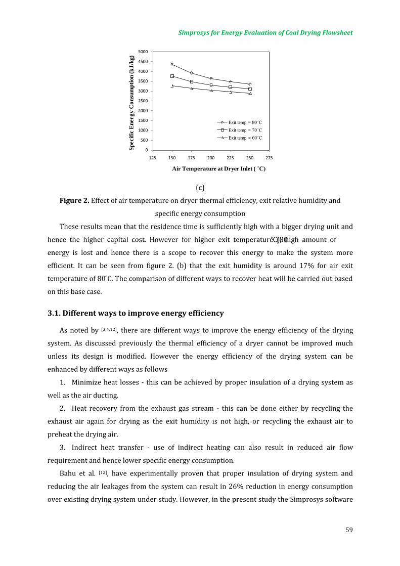
Simprosys for Energy Evaluation of Coal Drying Flowsheet
59
(c)
Figure 2. Effect of air temperature on dryer thermal efficiency, exit relative humidity and
specific energy consumption
These results mean that the residence time is sufficiently high with a bigger drying unit and
hence the higher capital cost. However for higher exit temperature (80˚C), high amount of
energy is lost and hence there is a scope to recover this energy to make the system more
efficient. It can be seen from figure 2. (b) that the exit humidity is around 17% for air exit
temperature of 80˚C. The comparison of different ways to recover heat will be carried out based
on this base case.
3.1. Different ways to improve energy efficiency
As noted by [3,4,12], there are different ways to improve the energy efficiency of the drying
system. As discussed previously the thermal efficiency of a dryer cannot be improved much
unless its design is modified. However the energy efficiency of the drying system can be
enhanced by different ways as follows
1. Minimize heat losses - this can be achieved by proper insulation of a drying system as
well as the air ducting.
2. Heat recovery from the exhaust gas stream - this can be done either by recycling the
exhaust air again for drying as the exit humidity is not high, or recycling the exhaust air to
preheat the drying air.
3. Indirect heat transfer - use of indirect heating can also result in reduced air flow
requirement and hence lower specific energy consumption.
Bahu et al. [12], have experimentally proven that proper insulation of drying system and
reducing the air leakages from the system can result in 26% reduction in energy consumption
over existing drying system under study. However, in the present study the Simprosys software
0
500
1000
1500
2000
2500
3000
3500
4000
4500
5000
125 150 175 200 225 250 275
Spec
ific
Ene
rgy
Con
sum
ptio
n (k
J/kg
)
Air Temperature at Dryer Inlet ( ˚C)
Exit temp = 80˚CExit temp = 70˚CExit temp = 60˚C

Simprosys for Energy Evaluation of Coal Drying Flowsheet
60
was used to analyze the effect of recycle air and the indirect heating on the specific energy
consumption.
3.2. Use of recycle air
The recovery of heat from exhaust air can be done either be recycling it back to the dryer or
by using it to pre-heat the drying air. The recycle of air to the dryer can be done in two ways;
either by mixing it with the heated fresh air at the dryer inlet or by mixing it with the fresh air
before heater. From the initial simulations it was found that the latter case is more beneficial
hence the results are reported only for the recycle of exhaust air before the heater. Figure 3
shows the flowsheet which uses the dryer exhaust air for pre-heating of the drying air.
Figure 3. Preheating of drying air using recycle air
To study the effect of preheating of the ambient air, the total volume of exhaust air is
recycled and the temperature of the purged air from the pre-heater was varied to study effect on
the specific energy consumption. It can be seen from figure 4 that the effect of preheating of
fresh air is more prominent at lower drying air temperatures however, as the temperature of the
purged air from pre-heater is lowered, the effect on specific energy consumption reduces. Figure
5 shows the flowsheet used to study the effect of recycle of dryer exhaust air back to the dryer
but before the air heater. It is explained previously that the recycle of dryer exhaust air back to
the dryer inlet does not help to improve the efficiency; the remaining volume of air is purged to
atmosphere. It should be noted from the figure that entire volume of exhaust drying air can be
recycled, however, the cost air pumping and air ducting should be taken into account while
selecting the recycle ratio. Figure 6 shows the effect of the recycle ratio of the dryer exhaust air
on the specific energy consumption and the exhaust air relative humidity. It can be seen that the
relative humidity of the exhaust air increases as the recycle ratio is increased, which means the
Fresh Air
Air Filter
Filtered Air
Fan 1 Exchanger 1
Before Exch
After Exch
Recycled Air
Heater 1
Dryer In Dryer
out
Dryer
Cyclone 1
Dry Coal
Wet Coal
Cyclone out
Solids from Cyclone
Fan 2

Simprosys for Energy Evaluation of Coal Drying Flowsheet
61
drying air is used more efficiently. This can also be seen from the graph of the specific energy
consumption values. The SEC decreases as the recycle ratio is increased. It is also possible to
study if the part of the air is recycled for drying and a part is used for the preheating of ambient
air. This probability was also simulated using Simprosys. For this case for example, a recycle
ratio of 0.7 means 70% air is recycled to dryer and 30% is used for preheating. These
simulations were carried out for the same dryer exit conditions. Figure 7 shows the effect of
recycle ratio on the specific energy consumption for both cases, recycle for only drying and
recycle for drying and pre-heating.
Figure 4. Effect of pre-heating of fresh air on specific energy consumption
Figure 5. Flowsheet for recycle of air to dryer
2000
2500
3000
3500
4000
4500
5000
125 150 175 200 225 250 275
Spec
ific
Ene
rgy
Con
sum
ptio
n (k
J/kg
)
Air Temperature at Dryer Inlet ( ˚C)
Without RecycleAir temp at pre-heater exit = 70̊ CAir temp at pre-heater exit = 60̊ CAir temp at pre-heater exit =50̊ C
Fresh Air
Air Filter
Filtered Air
Fan 1 Mixer 1
Before Exch
After Exch
Recycled Air
Heater 1
Dryer In Dryer
out
Dryer
Cyclone 1
Dry Coal
Wet Coal
Cyclone out
Solids from Cyclone
Fan 2
R

Simprosys for Energy Evaluation of Coal Drying Flowsheet
62
Figure 6. Effect of recycle ratio on exhaust air humidity and specific energy consumption
Figure 7. Effect of recycle and pre-heating on specific energy consumption
3.3. Effect of indirect heating
Coal, especially low rank coal is highly susceptible to spontaneous combustion hence using
high temperature air can result in increase of fire hazard. Use of indirect heat can reduce the
hazard as less air at lower temperatures can be used [11]. The use of indirect heating can result in
lower required air volume for drying. This can result in lower specific energy consumption,
lower air pumping cost as well as smaller ducting for drying air. Thus, efficient indirect heating
offers a number of advantages. Simprosys offers the advantage of easily incorporating indirect
heat for drying. This possibility was simulated for drying of low rank coals with the existing case.
Fig. 8 shows the effect of percentage of total required heat supplied by indirect heating. It can be
seen that the increase in the indirect heat results in higher dryer exit humidity and lower specific
energy consumption, this is because of the lower quantity of required drying air. This indicates
that the air is used more effectively. However, the extent of indirect heating will be limited by the
dew point of the drying air.
1000
1500
2000
2500
3000
3500
4000
0
0.1
0.2
0.3
0.4
0.5
0.6
0 0.2 0.4 0.6 0.8
Spec
ific
Ene
rgy
Con
sum
ptio
n (k
J/kg
)
Rel
ativ
e H
umid
ity a
t Dry
er E
xit (
-)
Recycle Ratio to Dryer
Relative humidity
Specific heat consumption
1500
2000
2500
3000
3500
4000
0 0.2 0.4 0.6 0.8
Spec
ific
Ene
rgy
Con
sum
ptio
n (k
J/kg
)
Recycle Ratio to Dryer
Unrecycled air purged outUnrecycled air for pre-heating

Simprosys for Energy Evaluation of Coal Drying Flowsheet
63
Figure 8. Effect of indirect heating on exit humidity and specific energy consumption
CLOSING REMARKS
Excessive heat losses and lack of heat recovery are the two important factors
responsible for lower energy efficiency of the drying systems. Most of the existing drying
processes have potential to improve their energy efficiency. This is very important for
drying of products such as coal, for which, it is very necessary to develop cost-effective
and sustainable drying system. Although it is difficult to experimentally study the use of
recycle and heat recovery, software such as Simprosys is very handy in determining
feasibility of alternative approaches to improve the energy efficiency.
It can be noted that Simprosys has great potential to carry out useful heat and mass
balances on complicated flowsheets to study the possibility for improvements in the
existing drying systems. Interested readers can visit www.simprotek.com for more
details. It is an easy-to-use tool for designers and students of heat and mass transfer as
well as engineering thermodynamics.
REFERENCES
[1] Mujumdar, A.S., Handbook of Industrial Drying, 3rd Ed; CRC Press: Boca Raton, FL,
2006.
[2] Mujumdar, A.S., Guide to Industrial Drying: Principles, Equipments & New
Developments, 3rd Ed; Three S Colors Publications, India, 2008.
[3] Gong, Z.X. and Mujumdar, A.S., Software for design and analysis of drying systems,
Drying Technology, Vol. 26(7), pp. 884-894, 2008.
0
500
1000
1500
2000
2500
3000
3500
4000
0
0.05
0.1
0.15
0.2
0.25
0.3
0.35
0.4
0.45
0.5
0 10 20 30 40 50 60
Spec
ific
Ene
rgy
Con
sum
ptio
n (k
J/kg
)
Dry
er E
xit A
ir H
umid
ity (-
)
% of Total Heat Transferred by Indirect Heating
Relative humiditySpecific energy cons

Simprosys for Energy Evaluation of Coal Drying Flowsheet
64
[4] Baker, C.G.J., Energy efficient dryer operation - an update on developments, Drying
Technology, Vol. 23(9), pp. 2071-2087, 2005.
[5] Kemp, I.C., Drying software: Past, present and future, Drying Technology, Vol. 25(7),
pp. 1249-1263, 2007.
[6] Kudra, T., Platon, R. and Navarri, P., Excel-based tool to analyze the energy
performance of convective dryers, Drying Technology, Vol. 27(12), pp. 1302-1308,
2009.
[7] Gong, Z.X. and Mujumdar, A.S., Simulation of drying nonaqueous systems - An
application of Simprosys software, Drying Technology, Vol. 28(1), pp. 111-115, 2010.
[8] Masters, K., Spray Drying Handbook, 4th Ed; John Wiley & Sons, 1985.
[9] Perry, R., Perry’s Chemical Engineers’ Handbook, 7th Ed; McGraw-Hill, 1997.
[10] Karthikeyan, M., Zhonghua, W. and Mujumdar, A.S., Low-rank coal drying
technologies - current status and new developments, Drying Technology, Vol. 27(3),
pp. 403-405, 2009.
[11] Jangam, S.V., Karthikeyan, M. and Mujumdar, A.S., A critical assessment of
industrial coal drying technologies: Role of energy, emissions, risk and sustainability,
Drying Technology, Accepted for publication, 2010.
[12] Bahu, R.E., Baker, C.G.J. and Reay, D., Energy balances on industrial dryers-A route
to fuel conservation, Journal of Separation Processes Technology, Vol. 4(4), pp. 23-
28, 1983.
Drying in Mineral Processing Industry: Potential for Innovation
W. Zhonghua and A.S. Mujumdar
Minerals, Metals and Materials technology Centre, National university of Singapore
Contents
1. INTRODUCTION ......................................................................................................................... 67
2. DEWATERING OF MINERALS ................................................................................................. 67
2.1. Conventional dewatering technologies for minerals ..................................................... 67
2.2. New Developments in the Dewatering Technology ........................................................ 68
2.2.1. Electro-dewatering ............................................................................................................ 68
2.2.2. Crossflow microfiltration ................................................................................................ 69
2.2.3. Enhanced dewatering with surfactants and flocculants ..................................... 70
2.2.4. Other improvements ........................................................................................................ 70
3. DRYING OF MINERALS ............................................................................................................. 71
3.1. Conventional Drying Techniques for Minerals ................................................................. 71
3.2. Emerging Drying Methods ........................................................................................................ 71
3.2.1. Superheated Steam Drying ............................................................................................. 71
3.2.2. Pulse combustion drying ................................................................................................. 73
3.2.3. Microwave drying .............................................................................................................. 74
3.2.4. Combined grinding and drying ..................................................................................... 75
3.2.5. Heat pump assisted drying ............................................................................................. 75
CLOSING REMARKS ........................................................................................................................ 76


Drying in Mineral Processing Industry: Potential for Innovation
67
1. INTRODUCTION
In the mineral industry, dewatering/ drying is generally carried out at the raw-materials or
product-handling stage; for example, after beneficiation or concentration the ore may require
drying to some optimum level to facilitate handling. The minerals are very often available as
solids, aqueous solutions or slurries with different particle sizes and distributions. Different
dewatering and drying technologies are used to dry minerals. Although dewatering and drying
are highly energy-intensive operations that are also increasingly difficult at lower moisture
contents, no special attention is generally given to the technical and economical aspects of the
dewatering/drying process employed in the mineral industry. It is therefore not surprising that
most dryers found in these industries are of the conventional type.
The objectives of this paper are to provide a global view of the types of dewater equipments
and dryers currently used in mineral processing industries and identify possible new concepts
that may be applicable in the mineral industry. With oil price in triple digits it is expected that
the mineral processing industry will need to re-evaluate their strategies to reduce their net
energy consumption and reduce environmental impact as well.
2. DEWATERING OF MINERALS
In the minerals industry, mechanical dewatering is employed in order to save the energy
required in thermal drying, improve the handling properties of the concentrates, and to reduce
transportation costs if the concentrates are to be shipped.
2.1. Conventional dewatering technologies for minerals
Conventional dewatering techniques utilize thickeners, dewatering screens, vacuum filters,
centrifuges, and pressure (hyperbaric) filters to reduce product moisture to a lower value. The
driving forces exerted in dewatering range from 50 to > 5000 g (for centrifuges) or -0.3- 200 bar
(for filters). In general, the greater the driving force exerted, the lower the throughput and the
higher the cost. Table 1 lists some current dewatering technologies for minerals. Choice of the
dewatering technology for a specific material is dependent on many factors such as particle size,
initial moisture content. Taking coal as example, dewatering screens, centrifuges and sieve
bends provide a low moisture product with 600+ µm coal, however, their efficiency decreases
rapidly with decreasing particle size. Dewatering of minus 600 µm fine coal is often
accomplished using either vacuum or pressure filtration.

Drying in Mineral Processing Industry: Potential for Innovation
68
Table 1. Conventional dewatering technologies for minerals
Dewatering Technology Characteristics of the dewatering methods
Gravity
Sedimentation thickeners
Employ principles of gravity settling and applied in mineral concentrates and tailings, high capacity, low maintenance and operating cost, big physical size.
Cyclones
Widely used in the mining industry. Design and operational simplicity, high capacity, low maintenance and operating cost, small physical size. Applied for classification or concentration.
Centrifuges
Vibrating basket centrifuges
The dilation and disturbance of the materials bed facilitates removal of water. Feed rate: 100 t/h. Product moisture: 5-10 wt%. Centrifugal force 60-75 g.
Scroll centrifuges
Feed rate: up to 60-70 t/h, Product moisture: 12-16 wt%. Feed solids: 40-55 wt%. Centrifugal force:110 g.
Filtration
Horizontal belt
Handle a wider range of feed size and flexible in its tolerance of feed changes and surges. Simple in design and low cost in flocculants and maintenance.
Drum filters Handle coarser feeds. A relatively small footprint and a lower capital cost. Tolerant to feed rate changes. Continuous operation.
Disc filters Handle coarser feeds. Compact design and low capital cost. A higher maintenance demand. Careful level control needed.
Mechanical thermal pressing
Mechanical expression (1-10 MPa) at elevated temperatures. Removal of 7% of moisture. Energy efficient operation. Changes in physical and chemical structure of minerals.
Disk and rotary drum vacuum filters are widely used in the U.S.A, which produces a filter cake
with about 30 percent moisture. Pressure filter is more effective than vacuum filters in lowering
the cake moisture, but capital and operating costs are high
2.2. New Developments in the Dewatering Technology
2.2.1. Electro-dewatering
Mechanical dewatering methods can extract the free water contained in the liquid sludge
relatively easily and efficiently by applying high pressure or vacuum. The resulting partially
dewatered sludge will still contain a relatively high percentage of water, but it consists mainly of
adsorbed water. Until electro-dewatering came along, only thermal treatment, which is costly in
terms of energy and capital, could extract the adsorbed water. The working principle of Electro-
dewatering is that the water in the sludge contains cations (positive ions) that, under the effect
of a continuous electrical current, are attracted by the negative pole--in this case, the cathode.
Through viscous action, the movement of the cations through the water in the sludge carries
water molecules towards the cathode, where the water is finally drained out of the sludge. To
compensate for the volume loss created by the extracted water, the distance between the anode

Drying in Mineral Processing Industry: Potential for Innovation
69
and the cathode is adjusted by applying a mechanical force to the electrodes and controlled
pressure to the sludge to be
dewatered. The resulting dewatered sludge can be very dry; by changing the operating
parameters, a dryness of 25 to 50% or greater can be achieved.
Lockhart (1983) carried out large-scale laboratory tests on pure clays and various fine
suspensions from mineral processing. In one field trial of electroosmotic dewatering in tailings
ponds at a coal washery using three horizontal electrodes, 570 t of material were dewatered to a
spadeable consistency (67% solids) in 2 weeks at 26-33 V for an energy consumption of about 9
kWh/t of starting material, or 20 kWh/t on a dry solids basis. A further 9.5 days dewatering at
33-40 V gave a dryer product (over 75% solids) for 36 kWh/t (dry). Gopalakrishnan et al. (1966)
reported vacuum dewatering of titanium oxohydrate and pyrite slurries was enhanced
electrokinetically through application of a constant DC voltage cross the bed. The powder was
applied either continuously or in an interrupted mode. The interrupted mode removed more
water than continuous power, with a lower consumption of energy. Additional water could be
removed in the interrupted model by adding base at the anode to neutralize the acidity produced
by the reaction at the anode when the power was on.
2.2.2. Crossflow microfiltration
Crossflow microfiltration is a technique that may be applied when processing very fine
minerals that will not settle or filter efficiently by conventional means. In crossflow filtration, the
suspension to be filtered is passed tangentially over the surface of the filter. The formation of a
filter cake is restricted by the shear at the membrane surface and the process is strongly
influenced by the rheology of the suspension. Crossflow microfilters are of modular design that
enables intermittent or transient application. The most appropriate crossflow filters for mineral
suspensions are perforated or porous tubes of 4-13 mm in diameter operating in parallel, which
can provide an extremely large filtering area enclosed in a small total volume. Alternative
crossflow filter designs include hollow fibre and spiral wound modules.
GE Osmonics, Inc (2006) holds a patent (U.S. Patent 7048855) on crossflow filtration
cartridges. The cartridges are made using semipermeable membrane of sheet formation that was
cast upon an integral polymeric fibrous support, which exhibits excellent permeate flow in the
plane. After gelling to form a polymeric semipermeable membrane, the product is spirally
wound about a porous tube in association with feed-passageway-providing sheet material, but in
the absence of any separate permeate carrier, to form an effective cross-flow filtration cartridge.
Holdich et al (1996) discussed the various scale-up and operating models of crossflow filtration
systems for both suspension thickening and washing free from a solute. A shear drag model was
Drying in Mineral Processing Industry: Potential for Innovation
70
developed for of the mineral crossflow filtration systems. It was found that the flux rate is very
important to process scale use.
2.2.3. Enhanced dewatering with surfactants and flocculants
In recent years, the need for improved floc conditioning is being increasingly recognized.
Options exist for improved and controlled mixing of flocculants into filter feeds, and also the use
of mixed flocculant formulations (anionic and cationic) to produce smaller tighter flocs, which in
turn can produce enhanced cake permeability without large increases in porosity. Two types of
chemical additives are available for industrial use: flocculants filter aids and surfactant
dewatering aids.
Sherex Chemical Company Inc (1993) reported that improved dewatering results are
achieved by adding to the mineral ore slurry an effective amount of a alkanol or alkanoic acid
wherein alkoxylation is dewatering aid comprising an alkoxylated C6-C11 conducted with
propylene oxide or butylene oxide. Mwaba (1991) studied the role of surfactants in the
dewatering of graphite and hematite suspensions. When the surfactant sodium di-(2-
eththylhexyl) sulphosuccinate, which adsorbs on both graphite and hematite surfaces, leads to
small but significant reductions in the final moisture contents of the filter cakes. These
enhancements attributed to the changes which surfactant adsorption causes in the wetting
characteristics of the mineral surfaces.
2.2.4. Other improvements
A recent development in the minerals industry is the use of ceramic filter media in vacuum
disc filters. The pores of these filters are so fine that air breakthrough is prevented, thus
permitting retention of higher vacuum levels and production of drier cakes. Also, some plants
have been testing hyperbaric pressure filters as a means of reducing product moisture. The
dewatering driving force is applied as an overpressure to the filter and is usually approximately
3 Bars. Compared with vacuum filtration, substantional reductions in products in product
moisture (6-10 wt%) and increases in throughput (up to 2.5 times higher) had been achieved. A
research project funded by The Centre for Mining Technology and Equipment reports
development of a pilot scale (approximate 3 t/h coal) of a novel technique to reduce product
moisture using coarse coal centrifuges. The technique involves injecting a turbulent stream of air
through the particle bed as it travels through the centrifuges. Reductions in product moisture of
up to 1 wt% have been achieved. Demonstrations on full-scale centrifuges are being planned.
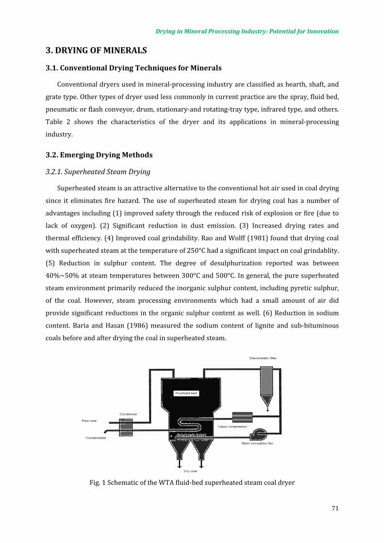
Drying in Mineral Processing Industry: Potential for Innovation
71
3. DRYING OF MINERALS
3.1. Conventional Drying Techniques for Minerals
Conventional dryers used in mineral-processing industry are classified as hearth, shaft, and
grate type. Other types of dryer used less commonly in current practice are the spray, fluid bed,
pneumatic or flash conveyor, drum, stationary-and rotating-tray type, infrared type, and others.
Table 2 shows the characteristics of the dryer and its applications in mineral-processing
industry.
3.2. Emerging Drying Methods
3.2.1. Superheated Steam Drying
Superheated steam is an attractive alternative to the conventional hot air used in coal drying
since it eliminates fire hazard. The use of superheated steam for drying coal has a number of
advantages including (1) improved safety through the reduced risk of explosion or fire (due to
lack of oxygen). (2) Significant reduction in dust emission. (3) Increased drying rates and
thermal efficiency. (4) Improved coal grindability. Rao and Wolff (1981) found that drying coal
with superheated steam at the temperature of 250°C had a significant impact on coal grindablity.
(5) Reduction in sulphur content. The degree of desulphurization reported was between
40%~50% at steam temperatures between 300°C and 500°C. In general, the pure superheated
steam environment primarily reduced the inorganic sulphur content, including pyretic sulphur,
of the coal. However, steam processing environments which had a small amount of air did
provide significant reductions in the organic sulphur content as well. (6) Reduction in sodium
content. Baria and Hasan (1986) measured the sodium content of lignite and sub-bituminous
coals before and after drying the coal in superheated steam.
Fig. 1 Schematic of the WTA fluid-bed superheated steam coal dryer
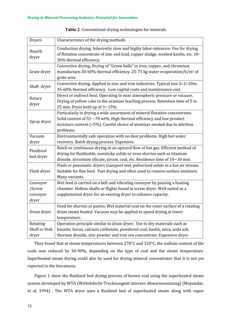
Drying in Mineral Processing Industry: Potential for Innovation
72
Table 2. Conventional drying technologies for minerals
They found that at steam temperatures between 270°C and 320°C, the sodium content of the
coals was reduced by 50-90%, depending on the type of coal and the steam temperature.
Superheated steam drying could also be used for drying mineral concentrates that it is not yet
reported in the literatures.
Figure 1 show the fluidized bed drying process of brown coal using the superheated steam
system developed by WTA (Wirbelshicht-Trocknungmit interner Abwarmenutzung) (Mujumdar,
et al, 1994) . The WTA dryer uses a fluidized bed of superheated steam along with vapor
Dryers Characteristics of the drying methods
Hearth dryer
Conduction drying. Inherently slow and highly labor-intensive. Use for drying of flotation concentrate of zinc and lead, copper sludge, washed kaolin, etc. 10-30% thermal efficiency.
Grate dryer Convective drying. Drying of "Green balls" in iron, copper, and chromium manufacture.30-60% thermal efficiency. 25-75 kg water evaporation/h/m2 of grate area
Shaft dryer Convective drying. Applied in zinc and iron industries. Typical size 2×2×20m. 35-60% thermal efficiency. Low capital costs and maintenance cost.
Rotary dryer
Direct or indirect heat. Operating in near atmospheric pressure or vacuum. Drying of yellow cake in the uranium leaching process. Retention time of 5 to 25 min. Dryer hold up of 3~15%.
Spray dryer
Particularly in drying a wide assortment of mineral flotation concentrates. Solid content of 55 ~70 wt%. High thermal efficiency and low product moisture content (<5%). Careful choice of atomizer needed due to attrition problems.
Vacuum dryer
Environmentally safe operation with no dust problems. High hot water recovery. Batch drying process. Expensive.
Fluidized bed dryer
Batch or continuous drying in an upward flow of hot gas. Efficient method of drying for fluidizable, nonsticky solids or even slurries such as titanium dioxide, zirconium silicate, zircon, coal, etc. Residence time of 10~30 min.
Flash dryer Flash or pneumatic dryers transport wet, pulverized solids in a hot air stream. Suitable for fine feed. Fast drying and often used to remove surface moisture. Many variants.
Conveyor /Screw conveyor dryer
Wet feed is carried on a belt and vibrating conveyor by passing a heating chamber. Hollow shafts or flights found in screw dryer. Well suited as a supplemental dryer for an existing dryer to enhance capacity.
Drum dryer Used for slurries or pastes. Wet material coat on the outer surface of a rotating drum steam heated. Vacuum may be applied to speed drying at lower temperature.
Rotating Shelf or Disk dryer
Operation principle similar to drum dryer. Use to dry materials such as bauxite, borax, calcium carbonate, powdered coal, kaolin, mica, soda ash, thorium dioxide, zinc powder and iron ore concentrate. Expensive dryer

Drying in Mineral Processing Industry: Potential for Innovation
73
compressors for recovering the latent heat from the processes. The coal is dried from 55-60%
moisture content down to 12% moisture. The flow rate of coal is 44 tons/hour of wet coal. In the
dryer, the steam is 110°C and 50 mbar. Some of the steam from the dryer is compressed to 4 bar
and 150°C for heating the fluidized bed in the dryer via submerged tubular heat exchanger
bundles in which this steam is condensed. Compared to the rotary steam-tube dryers, the WTA
superheated steam dryer is claimed to
• consume 80% less energy
• have 80% less dust emissions
have a smaller capital cost compared to rotary steam-tube dryers. In principle, any direct
dyers can be used with superheated steam as the drying medium. Since the dryer exhaust is also
superheated steam there is potential to recover the latent heat supplied by condensation or
compression after cleaning. This can reduce the energy consumption significantly relative to air
drying.
3.2.2. Pulse combustion drying
Pulse combustion (PC) is an intermittent (periodic) combustion process of gaseous, liquid or
solid fuels, which has promising application potential in drying. Pulse combustion drying
technology utilizes one or multiple pulse combustors to produce high temperature and high
velocity pulsating jets, which can be used for drying wet materials. Industrial applications of
pulse combustion to drying can be found mainly in spray drying, to a lesser extent in fluid bed
and flash drying. Short drying time, high energy efficiency, improved product quality and
environmentally friendly operation are noted as the key advantages of this drying technology.
Ellman (1966) first carried out experimental studies of lignite drying using a 205 kW pulse
combustor. The moisture content of lignite was reduced from the initial 35% (wet basis) to
below 10% with a product output of 20 T/h. In 1969, Ellman developed a more powerful lignite
dryer where the pulse combustor had a heat load of 713 kW and a combination of propane, 3%
reside and lignite was used as fuel. This pulse combustion dyer can produce 3.2 tons of brown
coal/hour.
Figure 2 present a pulse combustion spray drying installation developed by Hosokawa Bepex
Corporation, USA, which consists of a pulse combustor, a drying chamber of various
configurations and a cyclone (Wu, 2007). In a pulse combustion spray dryer, the hot high shear
and the intense pressure wave fronts instantly atomize the liquid or slurries into fine droplets
without the need for an atomizer. There is no need for a blower or a compressor to supply the
drying gas as in the case of a conventional spray dryer. Hosokawa Bepex have tested over 120
different materials and their results were reported to be encouraging with most products being
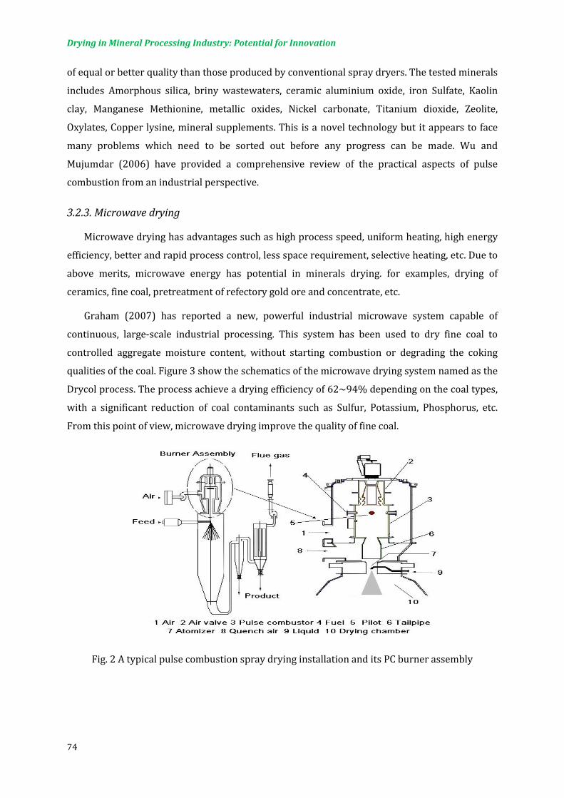
Drying in Mineral Processing Industry: Potential for Innovation
74
of equal or better quality than those produced by conventional spray dryers. The tested minerals
includes Amorphous silica, briny wastewaters, ceramic aluminium oxide, iron Sulfate, Kaolin
clay, Manganese Methionine, metallic oxides, Nickel carbonate, Titanium dioxide, Zeolite,
Oxylates, Copper lysine, mineral supplements. This is a novel technology but it appears to face
many problems which need to be sorted out before any progress can be made. Wu and
Mujumdar (2006) have provided a comprehensive review of the practical aspects of pulse
combustion from an industrial perspective.
3.2.3. Microwave drying
Microwave drying has advantages such as high process speed, uniform heating, high energy
efficiency, better and rapid process control, less space requirement, selective heating, etc. Due to
above merits, microwave energy has potential in minerals drying. for examples, drying of
ceramics, fine coal, pretreatment of refectory gold ore and concentrate, etc.
Graham (2007) has reported a new, powerful industrial microwave system capable of
continuous, large-scale industrial processing. This system has been used to dry fine coal to
controlled aggregate moisture content, without starting combustion or degrading the coking
qualities of the coal. Figure 3 show the schematics of the microwave drying system named as the
Drycol process. The process achieve a drying efficiency of 62~94% depending on the coal types,
with a significant reduction of coal contaminants such as Sulfur, Potassium, Phosphorus, etc.
From this point of view, microwave drying improve the quality of fine coal.
Fig. 2 A typical pulse combustion spray drying installation and its PC burner assembly

Drying in Mineral Processing Industry: Potential for Innovation
75
Fig. 3 The Drycol Process for fine coal
3.2.4. Combined grinding and drying
Sometimes drying may be achieved simultaneous with another operation. For example, heat
produced during grinding can be used effectively to reduce the moisture content significantly
while reducing the particle size. In some other applications, e.g. drying of sludge from a de-
inking plant, initial moisture content of 54% can be reduced to as low as 12% (wet basis) during
grinding. This also destroys any pathogens that may be present. One of the commercial grinder
dryers of interest to coal drying is the KDS Micronex grinder/dryer. A typical KDS grinder
chamber has a diameter of 1.3 m and encloses a set of 8 spinning chains and a stationary torus
above it. The chains are spun horizontally at high rotational speeds; the chain tip speed can
reach about 200 m/s causing high frictional heating due to aerodynamic drag. The bottom
surface of the torus which is flat provides a surface for the particles to collide on and shatter.
This results in grinding action accompanied by drying. The mechanism of drying is partly
thermal and partly mechanical dewatering. This saves on energy for drying. Air temperatures in
the chamber can reach between 70 and 90°C.
3.2.5. Heat pump assisted drying
For high thermal efficiency dryers, it is generally not economically justifiable to install heat-
recovery equipment to recover the low-graph heat in the exhaust gas. When the exhaust gas is at
high temperature for whatever reason, one must carefully evaluate the possibility of installing
heat-recovery systems for such dryer. The heat pump technology can efficiently recover the
waste heat and there has been a growing interest in recent years to apply the heat pump drying
technology to foods and biomaterials. It is also likely that heat-pump technology may find some
niche applications in the drying of minerals. There are no results of their use in the mineral
processing industry yet.

Drying in Mineral Processing Industry: Potential for Innovation
76
CLOSING REMARKS
An attempt is made to provide a general overview of competing drying/dewatering
processes for minerals. Some new dewatering/drying technologies are indentified such
as microfiltration, crossflow filtration, superheated steam drying, pulse combustion
drying. Specifically superheated steam drying of minerals such as pulverized coal is
being adopted as technology of choice due to its inherently high thermal efficiency and
safe operation since there is no danger of fire and explosion in this process. Pulse
combustion is a novel technology which has many distinct advantages. With the
increased global demand on minerals, it is expected that newer drying technologies will
emerge in the near future.
REFERENCES
Baria, D.N., Hasan, A.R. (1986), Steam/Hot Water Drying of Low Rank Coals, Energy
Progress, 6(1), 53-60
Ellman, R.C., Belter, J.W., Dockter, L. (1966), Adapting a Pulse-Jet Combustion System to
Entrained Drying of Lignite, Fifth International Coal Preparation Congress,
Pittsburgh, Pa., Oct 3-7, pp.463-476
Gapalakrishnan, S., Mujumdar, A.S., Weber, M.E., Prikonen, P.M. (1966), Filtration and
Separation, 33(10), pp.929-932
GE Osmonics Inc (2006), Cross flow filtration materials and cartridges. US patent
7048855
Graham, J. (2007), Microwaves for coal quality improvement: the DRYCOL project.
SACPS/ International Pittsburgh Coal Conference, Johannesburg, South Africa,
September, pp.10-14
Holdich, R.G., Cumming, I.W., Ismail, B. (1996), Crossflow microfiltration for mineral
suspension thickening and washing. Minerals Engineering, 9(2), pp.243-257
Lockhart, N.C. (1983), Electro-osmotic dewatering of fine tailings from mineral
processing. International Journal of Mineral Processing, 10, pp.131-140
Mujumdar, A. (2006), Handbook of Industrial Drying, 3rd edition, CRC Press, USA.

Drying in Mineral Processing Industry: Potential for Innovation
77
Mujumdar, A.S., Husain, H., Woods B. (1994), Techno-Economic Assessment of Potential
Superheated Steam Drying Applications in Canada. Technical Report of Canadian
Electrical Association 9138U888
Mwaba, C.C.(1991), Surfactant-enhanced dewatering of graphite and hematite
suspensions. Minerals Engineering, 4(1), pp.49-62
Rao, P.D., Wolff, E.N. (1981), Steam Drying of Subbituminous Coals from the Nenana and
Beluga Fields, a Laboratory Study. U.S. DOE report number DOE/ET/12222-T1
Sherex Chemical Company Inc (1993), Ore dewatering process and compositions
therefor. US patent 4990264
Veal. C. (1997), Coal dewatering: A review of current technology and new developments.
The Austrian Coal Review, 3, pp.28-33
Wu, Z.H. (2007), Mathematical modelling of pulse combustion and its innovative
applications to thermal drying, PhD thesis, National University of Singapore
Wu, Z.H., Mujumdar, A.S. (2006), Pulse combustion dryers, Chemical Industry Digest,
May, 2006, pp.58-65.


