Analysis and Verification of PCCP Stiffness Testing Using Non-Invasive Acoustics NJ AWWA Annual Conference Thursday, March 23, 2017 Leslie M B Steves, PE Project Engineer - New Jersey American Water Rasko Ojdrovic, Senior Principal – Simpson Gumpertz & Heger John Marciszewski, Director of Business Development - Echologics
Transcript
Analysis and Verification of PCCP Stiffness Testing Using Non-Invasive Acoustics
NJ AWWA Annual ConferenceThursday, March 23, 2017
Leslie M B Steves, PE Project Engineer - New Jersey American WaterRasko Ojdrovic, Senior Principal – Simpson Gumpertz & Heger
John Marciszewski, Director of Business Development - Echologics
Presentation Outline• Project Scope• PCCP Risk Management• New Jersey American Water Approach• Condition Assessment Elements
1. Desktop Study2. Acoustic Inspection
• Project Implementation and Results• Next Steps
Project Scope
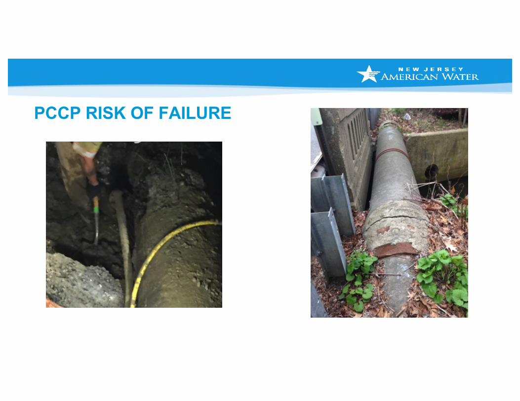
PCCP RISK OF FAILURE
AWWA - Buried No Longer
Asset Management – Life Cycle ManagementPlanning / Repair / Replacement
• 1 small break 48 hours: ~ $200,000
• Repair of 60 LF: ~ $3,000/LF
• Replacement of 20-inch: ~ $350/LF
• Planning for future replacement with Echologics and SG&H: ~ $17-27/LF*
• * Includes pothole costs from $5-10/LF
Asset Management – Accelerated Testing
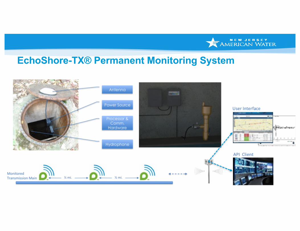
Vacuum Excavation – Permanent Monitoring Points
PULS – Echologics Support Services
ϴͬϲ/12 Page 2 of 3
AdjustableCasings
ConcreteCollar
MonitoringPoint Cover
lat 40.5507898ºlon -74.268428º
Installation of Permanent Monitoring Points
Step 1 – Utility Markout Whether completed by the utility owner or not, PULS will independently locate all requested utility lines. Any discrepancies in the location of the line versus the location depicted by PULS will be addressed with the utility owner prior to PULS conducting vacuum excavation. PULS will then assign all Monitoring Point (MP) locations.
Step 2 – Vacuum Excavation PULS will use vacuum excavation to locate and identify the utility line. Once the line has been located PULS will center the excavation over the midline of the utility line and create a shaft approximately 10” in diameter.
Step 3 – Installation of Monitoring Point The monitoring point is constructed of off-the-shelf components. There is an adjustable column that is standard for the municipal water authorities. It consists of two cast iron or plastic columns that screw together and allow for the adjustment of the column to grade. Upon completion of the column a 2’x2’ concrete collar is poured around the column and cast iron cap installed.
Step 4 – GPS Mapping of Monitoring Point The monitoring point will be mapped and the coordinates placed in GIS database. This will allow the monitoring point to be quickly located in the future or in the event of road construction.
Step 5 – Access to Monitoring Point The creation of a permanent monitoring point allows Echologics’ technicians the freedom to access the utility line quickly and easily. All without delays due to unforeseen obstructions in the excavation, weather or road conditions.
Pipe Excavation and Testing• 20 in. pipe excavation• 24 in. pipe bridge
INSPECTIONSSG&H performed detailed pipe inspections at two locations due to lack of any historical information related to the pipe
Failure Risk Analysis of PCCP• Evaluate the effects of broken prestressing wires on the pipe failure
margin using risk curves• Establish pipe repair priorities (immediate, mid term, no repair)• Identify high risk pipes for repair to maintain pipeline reliability
• Risk Curves:• Serviceability – onset of visible
cracking of core • Damage – core structural
cracking and increase in wire stress adjacent to BWZ
• Strength – pipe failure
Failure Risk Analysis• Corrosion of the steel
cylinder and likely leakage are expected prior to failure of the 20 in. and 24 in. diameter pipelines.
• Approximately 2 to 4 ft of prestress loss may result in failure of the pipes after steel cylinder corrosion and development of through holes.
Petrographic Analysis of Mortar Coating• No evidence of deterioration• Banded variation on paste color• Low chloride content in 20 in., and high in 24 in. pipe mortar
(possible salt spray from bridge)• High absorption
Soil Corrosivity Testing• Resistivity• pH• Sulfate content• Chloride content• Soil from 20 in. pipe excavation is not corrosive to PCCP per
AWWA M9 (pH = 5.21 < 5)• Samples from potholes will be tested in Phase II
Acoustic Wave Based Stiffness Testing• Purpose: Identify sections of pipeline with reduced structural stiffness• Survey level approach• Acoustic sensors measure the velocity of an acoustic wave in a pipe
segmentNoiseSource
Measuresoundvelocity
• Reduced wave speed may indicate reduced pipe wall stiffness and distress: § Broken prestressing wires, lower
Acoustic Wave Based Stiffness Testing• We calculated the nominal hoop stiffness of the 20/24 in. pipe
designs and compared that to the effective hoop stiffnessderived from the measured wave speeds according to the formula:
𝐾"## =2𝑐'
1𝜌*𝑣*,
− 1𝐾.
𝑐' accounts for longitudinal effects of bell & spigot joints, 𝜌* is the density of water, 𝑣* is the measured wave speed, and 𝐾. is the assumed bulk modulus of water.
ePulse Pipe Wall Stiffness Measurement• Review records for pipeline segments with lower stiffness (features,
other utilities, corrosivity, stray currents, high loads, etc.)• Placing sensors on fittings and branch lines increases variability
Recommendations
• Review segments with lower stiffness design and construction records, potential for soil corrosivity, stray currents, and other features that may affect pipe distress
• To identify leaking pipes that may be highly distressed, consider performing periodic leak detection or leak monitoring
• Review pipeline valve and pump operation and adjust as needed to keep transient pressures to a minimum to reduce the risk of pipe damage and failure
Next Steps….
• Permanent monitoring of the entire pipeline§ Leaks§ Pressure Transients
• Replacement of failed segments
• Follow the pyramid
§ Detailed external inspections of segments with lowest stiffness
§ Invasive assessment if required for confirmation