D-83 E2C-EDA E2C-EDA High Precision Positioning Inductive Proximity Sensor E2C-EDA • 1 μm resolution • Precision distance teaching Ordering Information Sensors Sensor Heads Note 1. A Protective Spiral Tube is provided with models ending in the suffix -S. (example: E2C-ED01-S). 2. Two cable lengths are available. (3-dia.: free-cut type, Heat-resistant type: standard-length only). Overall length of the standard-length type: 2.5 m, Length from the Sensor Head to the Preamplifier: 2.0 m (Example: E2C-ED01) Overall length of the free-cut type: 3.5 m, Length from the Sensor Head to the Preamplifier: 0.5 m for models ending in the suffix -F (ex- ample: E2C-ED01F). 3. Models ending in the suffix -S that come with Protective Spiral Tubes and free-cut models ending in the suffix -F are made-to-order prod- ucts. Type Appearance Sensing distance Repeat accuracy Model Shielded 3 dia. × 18 mm 1 µm E2C-EDR6-F (See note 2.) 5.4 dia. × 18 mm 1 µm E2C-ED01-@ (See notes 1, 2, and 3.) 8 dia. × 22 mm 2 µm E2C-ED02-@ (See notes 1, 2, and 3.) M10 × 22 mm 2 µm E2C-EM02-@ (See notes 1, 2, and 3.) 30 × 14 × 4.8 mm 2 µm E2C-EV05-@ (See notes 1, 2, and 3.) Unshielded M18 × 46.3 mm 5 µm E2C-EM07M-@ (See notes 1, 2, and 3.) Heat-resistant M12 × 22 mm 2 µm E2C-EM02H (See note 2.) Cylindrical 0.6 mm 1 mm 2 mm Screw 2 mm Flat 5 mm Screw 7 mm Screw 2 mm
Transcript
D-83E2C-EDA
E2C
-ED
A
High Precision Positioning Inductive Proximity Sensor
Note 1. A Protective Spiral Tube is provided with models ending in the suffix -S. (example: E2C-ED01-S).2. Two cable lengths are available. (3-dia.: free-cut type, Heat-resistant type: standard-length only).
Overall length of the standard-length type: 2.5 m, Length from the Sensor Head to the Preamplifier: 2.0 m (Example: E2C-ED01) Overall length of the free-cut type: 3.5 m, Length from the Sensor Head to the Preamplifier: 0.5 m for models ending in the suffix -F (ex-ample: E2C-ED01F).
3. Models ending in the suffix -S that come with Protective Spiral Tubes and free-cut models ending in the suffix -F are made-to-order prod-ucts.
Type Appearance Sensing distance Repeat accuracy Model
Shielded 3 dia. × 18 mm 1 µm E2C-EDR6-F (See note 2.)
5.4 dia. × 18 mm 1 µm E2C-ED01-@ (See notes 1, 2, and 3.)
8 dia. × 22 mm 2 µm E2C-ED02-@ (See notes 1, 2, and 3.)
M10 × 22 mm 2 µm E2C-EM02-@ (See notes 1, 2, and 3.)
30 × 14 × 4.8 mm 2 µm E2C-EV05-@ (See notes 1, 2, and 3.)
Unshielded M18 × 46.3 mm 5 µm E2C-EM07M-@ (See notes 1, 2, and 3.)
Heat-resistant M12 × 22 mm 2 µm E2C-EM02H (See note 2.)
Cylindrical0.6 mm
1 mm
2 mm
Screw
2 mm
Flat
5 mm
Screw
7 mm
Screw
2 mm
F502-EN2-04.book Seite 83 Dienstag, 26. Juli 2005 5:48 17
D-84 Inductive Sensors
Amplifier Units
Amplifier Units with Cables
Amplifier Units with Connectors
Amplifier Unit Connectors (Order Separately)
Mobile Console (Order Separately)
Note:Use the E3X-MC11-SV2 Mobile Console with E2C-EDA-series Amplifier Units. If you use a Mobile Console like the E3X-MC11-S, somefunctions may not operate.
Item Appearance Functions Model
NPN output PNP output
Advanced models Twin-output models Area output, open circuit detection, differential oper-ation
F502-EN2-04.book Seite 84 Dienstag, 26. Juli 2005 5:48 17
D-85E2C-EDA
E2C
-ED
A
Accessories (Order Separately)
Mounting Bracket
End Plate
Specifications
Sensor Heads
Note 1. The repeat accuracy and temperature characteristic are for a standard sensing object positioned midway through the rated sensing distance.2. A sudden temperature rise even within the rated temperature range may degrade characteristics.3. For the Sensor Head only without the preamplifier ( 10 to 60° C). With no icing or condensation.4. Do not operate in areas exposed to water vapor because the enclosure is not waterproof.
Appearance Model Quantity
E39-L143 1
Appearance Model Quantity
PFP-M 1
Model E2C-EDR6-F E2C-ED01(-@) E2C-ED02(-@) E2C-EM02-@) E2C-EM07(-@) E2C-EV05(-@) E2C-EM02H
Item 3 dia. × 18 mm 5.4 dia. × 18 mm 8 dia. × 22 mm M10 × 22 mm M18 × 46.3 mm 30 × 14 × 4.8 mm M12 × 22 mm
Sensing distance 0.6 mm 1 mm 2 mm 7 mm 5 mm 2 mmSensing object Magnetic metal (The sensing distance will decrease when sensing non-magnetic metal. Refer to Engineering Data on 87.)
Standard sensing object 5 × 5 × 3 mm10 × 10 × 3 mm 22 × 22 × 3
mm15 × 15 × 3 mm
20 × 20 × 3 mm
Material: iron (S50C)
Repeat accuracy (See note 1.)
1 µm 2 µm 5 µm 2 µm
Hysteresis distance Variable
Temper-ature charac-teristic (See note 1.)
Sensor Head 0.3%/° C 0.08%/° C 0.04%/° C 0.2%/° CPreamplifier and Amplifier
0.08%/° C
Ambient tempera-ture (See note 2.)
Operating –10° C to 60° C (with no icing or condensation) –10° C to 200° C (See note 3.)
Storage –10° C to 60° C (with no icing or condensation)
–20° C to 70° C (with no icing or condensation)
Ambient humidity Operating/storage: 35% to 85% (with no condensation)
Insulation resistance 50 MΩ min. (at 500 VDC)
Dielectric strength 1,000 VAC at 50/60 Hz for 1 min between current carry parts and case
Vibration resistance Destruction: 10 to 55 Hz, 1.5-mm double amplitude for 2 hours each in X, Y, and Z directions
Shock resistance Destruction: 500 m/s2 for 3 times each in X, Y, and Z directionsDegree of protection IEC60529 IP67 IEC60529
IP60 (See note 4.)
Connection method Connector (standard cable length: 2.5 m (2 m between Head and Preamplifier)“-F” model cable length: 3.5 m (0.5 m between Head and Preamplifier)
Weight (packed state) Approx. 120 g (Models with protective spiral tube (“-S” models) are approx. 90 g heavier.)
Material Sensor Head
Case Brass Stainless steel Brass Zinc BrassSensing surface
F502-EN2-04.book Seite 85 Dienstag, 26. Juli 2005 5:48 17
D-86 Inductive Sensors
Amplifier Units
Note:Communications are disabled if the detection mode is selected during super-high-speed sensing mode, and the communications functionsfor mutual interference prevention and the Mobile Console will not function.
Type Advanced Models with Twin Outputs Advanced Models with External Inputs
Model NPN output E2C-EDA11 E2C-EDA6 E2C-EDA21 E2C-EDA7
Supply voltage 12 to 24 VDC ±10%, ripple (p-p): 10% max.
Power consumption 1,080 mW max. (current consumption: 45 mA at power supply voltage of 24 VDC)
Control output Load power supply voltage: 26.4 VDC max.; NPN/PNP open collector output; load current: 50 mA max. (residual voltage: 1 V max.)
Response time Super-high-speed mode
150 µs for operation and reset respectively
High-speed mode 300 µs for operation and reset respectively
Standard mode 1 ms for operation and reset respectively
High-resolution mode
4 ms for operation and reset respectively
Functions Differential detec-tion
Switchable between single edge and double edge detection modeSingle edge: Can be set to 300 µs, 500 µs, 1 ms, 10 ms, or 100 msDouble edge: Can be set to 500 µs, 1 ms, 2 ms, 20 ms, or 200 ms.
Timer function Select from OFF-delay, ON-delay, or one-shot timer.1 ms to 5 s (1 to 20 ms set in 1-ms increments, 20 to 200 ms set in 10-ms increments,200 ms to 1 s set in 100-ms increments, and 1 to 5 s set in 1 s-increments)
Zero-reset Negative values can be displayed. (Threshold is not shifted.)
Initial reset Settings can be returned to defaults as required.
Mutual interfer-ence prevention
Possible for up to 5 Units. (See note.)Intermittent oscillation method (Response time = (number of Units connected + 1) × 15 ms)
Hysteresis set-tings
Setting range: 10 to 4,000
I/O settings Output setting (Select from channel 2 output, area output, self-diagnosis, or open circuit detection.)
Input setting (Select from teaching, fine positioning, zero-reset, synchronous detection.)
Digital display Select from the following: Incident level + threshold, incident level percentage +threshold, incident light peak level + incident light bottom level (updated with output), long bar display, incident level + peak hold, incident level + channel
Display orientation Switching between normal/reversed display is possible.
Ambient temperature Operating: When connecting 1 to 2 Units: –10° C to 55° CWhen connecting 3 to 5 Units: –10° C to 50° CWhen connecting 6 to 16 Units: –10° C to 45° C
When used in combination with an EDR6-F When connecting 3 to 4 Units: –10° C to 50° CWhen connecting 5 to 8 Units: –10° C to 45° CWhen connecting 9 to 16 Units: –10° C to 40° C
Storage: –20° C to 70° C (with no icing)
Ambient humidity Operating/storage: 35% to 85% (with no condensation)
Insulation resistance 20 MΩ min. (at 500 VDC)
Dielectric strength 1,000 VAC at 50/60 Hz for 1 min
Vibration resistance Destruction: 10 to 55 Hz, 1.5-mm double amplitude for 2 hours each in X, Y, and Z directions
Shock resistance Destruction: 500 m/s2 for 3 times each in X, Y, and Z directionsDegree of protection IEC60529 IP50
Connection method Prewired Connector Prewired ConnectorWeight (packed state) Approx. 100 g Approx. 55 g Approx. 100 g Approx. 55 gMaterial Case PBT (polybutylene terephthalate)
Cover Polycarbonate
F502-EN2-04.book Seite 86 Dienstag, 26. Juli 2005 5:48 17
D-87E2C-EDA
E2C
-ED
A
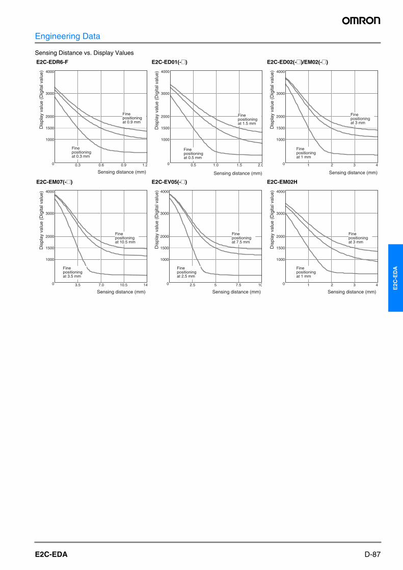
Engineering Data
Sensing Distance vs. Display Values
E2C-EDR6-F E2C-ED01(-@) E2C-ED02(-@)/EM02(-@)
E2C-EM07(-@) E2C-EV05(-@) E2C-EM02H
4000
3000
2000
1500
1000
0 0.3 0.6 0.9 1.2
Dis
play
val
ue (
Dig
ital v
alue
)
Sensing distance (mm)
Fine positioning at 0.9 mm
Fine positioning at 0.3 mm
4000
3000
2000
1500
1000
0 0.5 1.0 1.5 2.0
Dis
play
val
ue (
Dig
ital v
alue
)
Sensing distance (mm)
Fine positioning at 1.5 mm
Fine positioning at 0.5 mm
4000
3000
2000
1500
1000
0 1 2 3 4
Dis
play
val
ue (
Dig
ital v
alue
)
Sensing distance (mm)
Fine positioning at 3 mm
Fine positioning at 1 mm
4000
3000
2000
1500
1000
0 3.5 7.0 10.5 14
Dis
play
val
ue (
Dig
ital v
alue
)
Sensing distance (mm)
Fine positioning at 10.5 mm
Fine positioning at 3.5 mm
4000
3000
2000
1500
1000
0 2.5 5 7.5 10
Dis
play
val
ue (
Dig
ital v
alue
)
Sensing distance (mm)
Fine positioning at 7.5 mm
Fine positioning at 2.5 mm
4000
3000
2000
1500
1000
0 1 2 3 4
Dis
play
val
ue (
Dig
ital v
alue
)
Sensing distance (mm)
Fine positioning at 3 mm
Fine positioning at 1 mm
F502-EN2-04.book Seite 87 Dienstag, 26. Juli 2005 5:48 17
D-88 Inductive Sensors
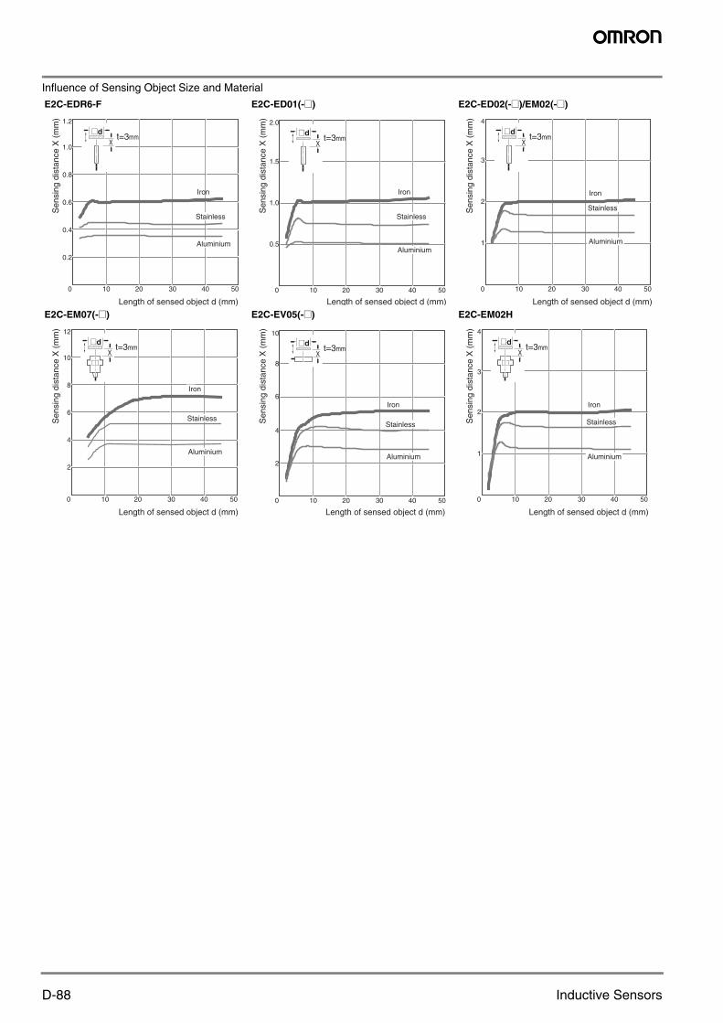
Influence of Sensing Object Size and Material
E2C-EDR6-F E2C-ED01(-@) E2C-ED02(-@)/EM02(-@)
E2C-EM07(-@) E2C-EV05(-@) E2C-EM02H
1.2
1.0
0.8
0.6
0.4
0.2
0 10 20 30 40 50
Sen
sing
dis
tanc
e X
(m
m)
Length of sensed object d (mm)
Iron
Stainless
Aluminium
@dt=3mm
X
2.0
1.5
1.0
0.5
0 10 20 30 40 50
@dt=3mm
X
Sen
sing
dis
tanc
e X
(m
m)
Length of sensed object d (mm)
Iron
Stainless
Aluminium
4
3
2
1
0 10 20 30 40 50
@dt=3mm
X
Sen
sing
dis
tanc
e X
(m
m)
Length of sensed object d (mm)
Iron
Stainless
Aluminium
@dt=3mm
X
12
10
8
6
4
2
0 10 20 30 40 50
Sen
sing
dis
tanc
e X
(m
m)
Length of sensed object d (mm)
Iron
Stainless
Aluminium
@dt=3mm
X
10
8
6
4
2
0 10 20 30 40 50
Sen
sing
dis
tanc
e X
(m
m)
Length of sensed object d (mm)
Iron
Stainless
Aluminium
@dt=3mm
X
4
3
2
1
0 10 20 30 40 50
Sen
sing
dis
tanc
e X
(m
m)
Length of sensed object d (mm)
Iron
Stainless
Aluminium
F502-EN2-04.book Seite 88 Dienstag, 26. Juli 2005 5:48 17
D-89E2C-EDA
E2C
-ED
A
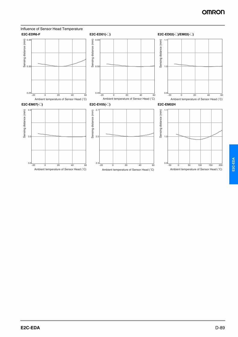
Influence of Sensor Head Temperature
E2C-EDR6-F E2C-ED01(-@) E2C-ED02(-@)/EM02(-@)
E2C-EM07(-@) E2C-EV05(-@) E2C-EM02H
0.35
0.30
0.25 −20 0 20 40 60
Sen
sing
dis
tanc
e (m
m)
Ambient temperature of Sensor Head (˚C)
0.55
0.50
0.45 −20 0 20 40 60
Sen
sing
dis
tanc
e (m
m)
Ambient temperature of Sensor Head (˚C)
1.1
1.0
0.9 −20 0 20 40 60
Sen
sing
dis
tanc
e (m
m)
Ambient temperature of Sensor Head (˚C)
4.0
3.5
3.0 −20 0 20 40 60
Sen
sing
dis
tanc
e (m
m)
Ambient temperature of Sensor Head (˚C)
2.7
2.5
2.3 −20 0 20 40 60
Sen
sing
dis
tanc
e (m
m)
Ambient temperature of Sensor Head (˚C)
1.1
1.0
0.9 −50 0 50 100 150 200
Sen
sing
dis
tanc
e (m
m)
Ambient temperature of Sensor Head (˚C)
F502-EN2-04.book Seite 89 Dienstag, 26. Juli 2005 5:48 17
D-90 Inductive Sensors
Operation
NPN Output
Note 1. Setting Areas for Twin-output ModelsNormally open: ON between the thresholds for Channel 1 and Channel 2Normally closed: OFF between the thresholds for Channel 1 and Channel 2
2. Timing Charts for Timer Settings (T: Set Time)
Model Operation mode
Timing chart Mode selector
Output circuit
E2C-EDA11E2C-EDA6
NO (Normally open)
NO
NC (Normally closed)
NC
E2C-EDA21E2C-EDA7
NO (Normally open)
NO
NC (Normally closed)
NC
ON delay OFF delay One shot
Yes
No
Lit
Not lit
ON
OFF
Operate
Reset
Operation indicator (orange)
(Between brown and black lines)
Output transistor
Load (relay,etc.)
Sensing object
Operation indicator(orange) ch2
Control output ch1
Control output ch2
Orange 12 to 24VDC
Operation indicator (orange) ch1Display
Load
Load
Brown
Black
Blue
Proximity Sensor main circuits
Yes
No
Lit
Not lit
ON
OFF
Operate
Reset
Operation indicator (orange)
(Between brown and black lines)
Output transistor
Load (relay,etc.)
Sensing object
Yes
No
Lit
Not lit
ON
OFF
Operate
Reset
Operation indicator (orange)
(Between brown and black lines)
Output transistor
Load (relay,etc.)
Sensing object
Control output
External input
Orange12 to 24VDC
Operation indicator (orange)
Display
Fine positioning indicator (orange)
Load
Brown
Black
Blue
Proximity Sensor main circuits
Yes
No
Lit
Not lit
ON
OFF
Operate
Reset
Operation indicator (orange)
(Between brown and black lines)
Output transistor
Load (relay,etc.)
Sensing object
Yes
No
ON
OFF
ON
OFF
NO
NC
T
T
Sensing object
Yes
No
ON
OFF
ON
OFF
NO
NC
T
T
Sensing object
Yes
No
ON
OFF
ON
OFF
NO
NC
T
T
Sensing object
F502-EN2-04.book Seite 90 Dienstag, 26. Juli 2005 5:48 17
D-91E2C-EDA
E2C
-ED
A
PNP Output
Note 1. Setting Areas for Twin-output ModelsNormally open: ON between the thresholds for Channel 1 and Channel 2Normally closed: OFF between the thresholds for Channel 1 and Channel 2
2. Timing Charts for Timer Settings (T: Set Time)
Nomenclature
Amplifier Units
Twin-output Models(E2C-EDA11/EDA41/EDA6/EDA8)
External-input Models(E2C-EDA21/EDA51/EDA7/EDA9)
Model Operation mode
Timing chart Mode selector
Output circuit
E2C-EDA41E2C-EDA8
NO (Normally open)
NO
NC (Normally closed)
NC
E2C-EDA51E2C-EDA9
NO (Normally open)
NO
NC (Normally closed)
NC
ON delay OFF delay One shot
Yes
No
Lit
Not lit
ON
OFF
Operate
Reset
Operation indicator (orange)
(Between blue and black lines)
Output transistor
Load (relay,etc.)
Sensing object
OrangeLoad
Load
Brown
Black
Blue
Proximity Sensor main circuits
Operation indicator(orange) ch2
Control output ch1
Control output ch2
12 to 24VDC
Operation indicator (orange) ch1Display
Yes
No
Lit
Not lit
ON
OFF
Operate
Reset
Operation indicator (orange)
(Between blue and black lines)
Output transistor
Load (relay,etc.)
Sensing object
Yes
No
Lit
Not lit
ON
OFF
Operate
Reset
Operation indicator (orange)
(Between blue and black lines)
Output transistor
Load (relay,etc.)
Sensing object
Load
Brown
Black
Blue
Proximity Sensor main circuits
Control output
External input
12 to 24VDC
Operation indicator (orange)Display
Fine positioning indicator (orange)
Orange
Yes
No
Lit
Not lit
ON
OFF
Operate
Reset
Operation indicator (orange)
(Between blue and black lines)
Output transistor
Load (relay,etc.)
Sensing object
Yes
No
ON
OFF
ON
OFF
NO
NC
T
T
Sensing object
Yes
No
ON
OFF
ON
OFF
NO
NC
T
T
Sensing object
Yes
No
ON
OFF
ON
OFF
NO
NC
T
T
Sensing object
Displays the incident light level or the function name.
Displays the threshold valuesand function settings.
Function setting operations
UP
DOWN
MODE
Used to select the channel to display or set.
Used to select SET or RUN mode.ON when output is ON.OFF when output is OFF.
ON when output is ON.OFF when output is OFF.
Operation Indicator for Channel 1 (Orange)
Main Display (Red) Sub-Display (Green) Operation Keys
Channel Selector
SET/RUN Mode Selector
Operation Indicator for Channel 2 (Orange)
UP
DOWN
MODE
Used to select normally open or normally closed.
Fine positioning setting
Operating Mode Selector
Fine Positioning Indicator(Orange)
Displays the incident light level or the function name.
Displays the threshold valuesand function settings. Function setting operations
Used to select SET or RUN mode.ON when output is ON.OFF when output is OFF.
Operation Indicator (Orange)
Main Display (Red) Sub-Display (Green)Operation Keys
SET/RUN Mode Selector
F502-EN2-04.book Seite 91 Dienstag, 26. Juli 2005 5:48 17
D-92 Inductive Sensors
Precautions
Precautions for Correct UseDo not use this product in operating atmospheres or environments outside the specified ratings.
Amplifier Units
Design
Power ONThe Sensor is ready to sense an object within 200 ms after turning the power ON. If the load and Sensor are connected to different power supplies, always turn ON the Sensor power first.
Connecting Sensor Heads
Connecting and Disconnecting Sensor Heads
1. Open the protective cover.2. Making sure that the lock button is up, insert the fibers all the way
to the back of the Connector insertion opening.
To disconnect the Sensor Head, pull out the fibers while pressing on the lock button.
Connecting and Disconnecting ConnectorsConnecting Connectors
1. Insert the Master or Slave Connector into the Amplifier Unit until it clicks into place.
2. Apply the supplied seal to the non-connection surface of the Mas-ter/Slave Connector.
Note:Apply the seal to the grooved side.
Disconnecting Connectors
1. Slide the Slave Amplifier Unit.2. After the Amplifier Unit has been separated, press down on the
lever on the Connector and remove it. (Do not attempt to remove Connectors without separating them from other Amplifier Units first.)
Installing and Removing Amplifier UnitsInstalling Amplifier Units
1. Install the Units one by one to the DIN rail.
2. Slide one Unit toward the other, match the clips at the front ends, and then bring them together until they “click.”
Removing Amplifier UnitsSlide one Unit away from the other and remove them one by one. (Do not remove the connected Units together from the DIN rail.)
End Plate Mounting (PFP-M)Mount End Plates on Amplifier Units to avoid movement due to vibra-tion. When a Mobile Console is installed, mount the End Plate facing as shown in the following diagram.
Do not use this product in any safety device used for the protection of human lives.
1
2
Lock button
Insert
Protector seal
Power supply Connector
Note 1. When the Amplifier Units are connected to each other, the operable ambient temperature changes depending on the number of connected Amplifier Units. Check Specifications.
2. Before connecting or disconnecting the Units, always switch power OFF.
Remove
LeverPress down.
Sensor Head Connector Clips
DIN rail
1
2
DIN rail
1
12
End Plate
F502-EN2-04.book Seite 92 Dienstag, 26. Juli 2005 5:48 17
D-93E2C-EDA
E2C
-ED
A
Mounting a Communications Head for the Mobile ConsoleLeave a space of at least 20 mm on the left side of the Units for a Mobile Console Communications Head.
EEPROM Write ErrorIf the data is not written to the EEPROM correctly due to a power failure or static-electric noise, initialize the settings using the keys on the Amplifier Unit.
Optical CommunicationsWhen using more than one Amplifier Unit, mount the Units side-by-side. Do not slide or remove Units while they are in use.
Miscellaneous
Protective CoverBe sure to put on the Protective Cover before use.
Mobile ConsoleUse the E3X-MC11-SV2 Mobile Console for E2C-EDA-series Ampli-fier Units. Other Mobile Consoles, such as the E3X-MC11, cannot be used.
Sensor Head and Amplifier Unit ConnectionBe sure to use only specified Sensor Head and Amplifier Unit combi-nations. The E3C-LDA-series Photoelectric Sensor with Separate Digital Amplifier is not compatible, and the E2C-EDA must not be used with products from that series.
Warm-upThe digital display will slowly change until the circuits stabilize after the power is turned ON. It takes about 30 minutes after the power is turned ON before the E2C-EDA is ready to sense.
Maintenance Inspection• Be sure to turn OFF the power before adjusting, connecting, or dis-
connecting the Sensor Head.
• Do not use thinner, benzene, acetone, or kerosene to clean the Sensor Head or Amplifier Unit.
Sensor Heads
Mounting
Mounting Sensor Heads• Use the dimensions from the following table to mount unthreaded
cylindrical models (E2C-ED-@@). Do not tighten screws with torque exceeding 0.2 N·m when mounting Sensor Heads.
• Use the torque given in the following table to tighten threaded cylin-
drical models (E2C-EM@@).
• Do not use torque exceeding 0.5 N·m to tighten screws when mounting flat models (E2C-EV@@).
• Use a bending radius of at least 8 mm for the Sensor Head cable.
• Use only the special extension cable to extend the cable between the Sensor Head and the Amplifier Unit. Consult your OMRON rep-resentative for details.
Effects of Surrounding Metal• Provide a minimum distance between the Sensor and the sur-
rounding metal as shown in the table below.
Effects of Surrounding Metal (Units: mm)
Mutual Interference• If more than one Sensor Head is installed face to face or in parallel,
make sure that the distances between two Units adjacent to each other are the same as or larger than the corresponding values shown in the following table.
• The distance between Sensor Heads may be narrower than speci-fied with these Sensors because the Mutual Interference Preven-tion Function is used for optical communications between the Amplifier Units.
Mutual Interference (Units: mm)
Model Tightening torque
E2C-EM02@@ 15 N·m max.
E2C-EM07M@@ 15 N·m max.
E2C-EM02H@@ 5.9 N·m max.
20 mm
Model Tightening range A
E2C-EDR6-F 9 to 18 mm
E2C-ED01@@ 9 to 18 mm
E2C-ED02@@ 11 to 12 mm
Dimpled end of set screw
E2C-ED@@
Model Face-to-face ar-
rangement A
Parallel ar-rangement
B
Face-to-face arrangement using the Mu-tual Interfer-
ence Prevention Function A'
Parallel ar-rangement
using the Mu-tual Interfer-
ence Prevention Function B'
E2C-EDR6-F 14 10 3.5 3.1
E2C-ED01@@ 45 20 9 5.4
E2C-ED02@@ 35 30 21 8
E2C-EM02@@ 36 30 21 10
E2C-EM07M@@ 140 120 35 18
E2C-EV05@@ 65 30 21 14
E2C-EM02H@@ 45 30 21 12
Model Counterbore A Protrusion B
E2C-EDR6-F 3.1 0
E2C-ED01@@ 5.4 0
E2C-ED02@@ 8 0
E2C-EM02@@ 10 0
E2C-EM07M@@ 35 20
E2C-EV05@@ 14 × 30 4.8
E2C-EM02H@@ 12 0
B
A dia.
A B
F502-EN2-04.book Seite 93 Dienstag, 26. Juli 2005 5:48 17
D-94 Inductive Sensors
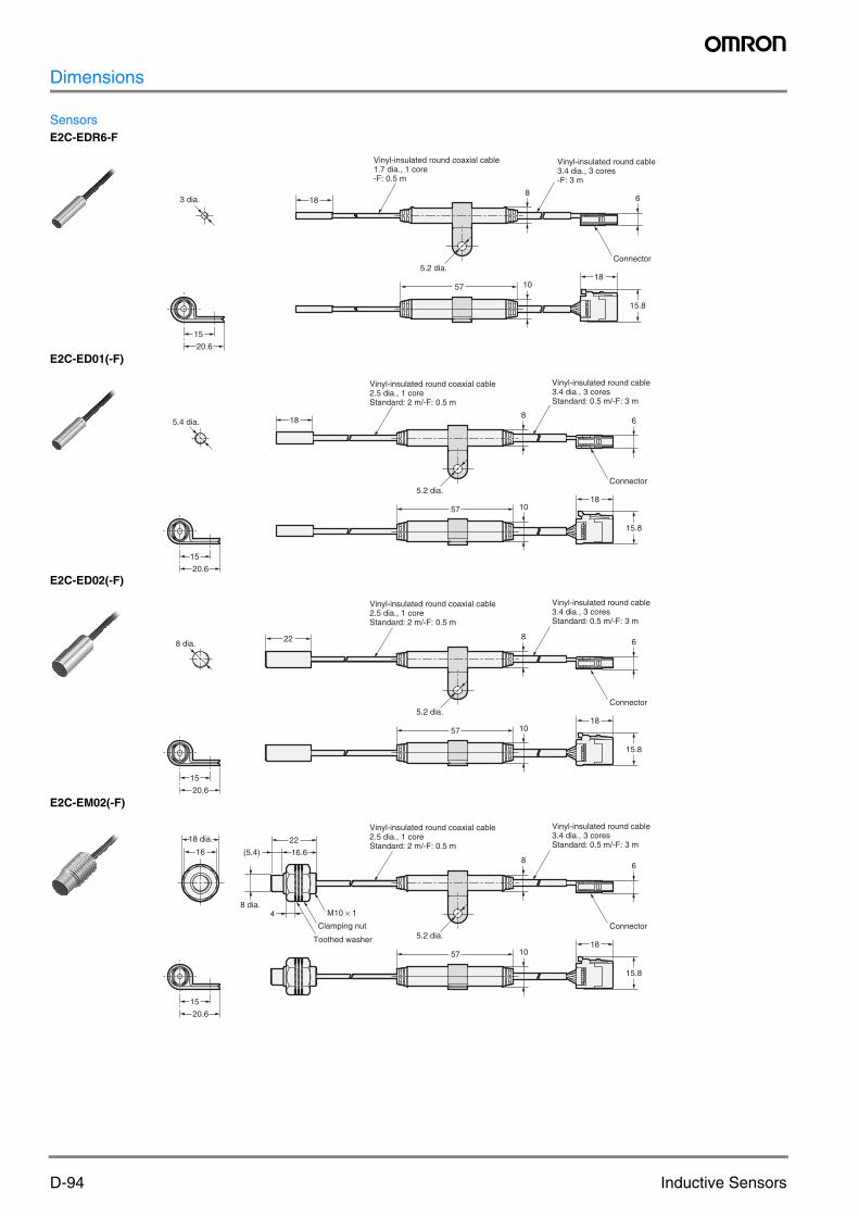
Dimensions
SensorsE2C-EDR6-F
E2C-ED01(-F)
E2C-ED02(-F)
E2C-EM02(-F)
3 dia. 18
Vinyl-insulated round coaxial cable1.7 dia., 1 core-F: 0.5 m
5.2 dia.
8
Vinyl-insulated round cable3.4 dia., 3 cores-F: 3 m