Digital Temperature Controllers E5@Z 1 Digital Temperature Controllers E5@Z Compact and Intelligent General-purpose Temperature Controllers • Various temperature inputs: thermocouple, platinum re- sistance thermometer, infrared temperature sensor, and analog inputs. • Auto-tuning and self-tuning available. Auto-tuning is possible even while self-tuning is being executed. • Heating or heating/cooling control is available. • Event input allows multi-SP selection and run/stop func- tion. • CE marking and UL/CSA certification. (CE marking and UL/CSA certification are pending for the E5EZ-PRR.) ® Contents Digital Temperature Controllers E5AZ ............................................................ 2 E5EZ ............................................................ 7 E5CZ ............................................................ 12 E5EZ-PRR.................................................... 29 Common to All Controllers • Nomenclature ............................................... 17 • Operation...................................................... 19 • Peripheral Devices ....................................... 28 • Safety Precautions ....................................... 52 E5@Z Series E5AZ 1/4 DIN 1/8 DIN E5EZ E5CZ 1/16 DIN 1/8 DIN E5EZ-PRR Digital Position- Proportional Controller
Transcript
Digital Temperature Controllers E5@Z 1
Digital Temperature ControllersE5@Z
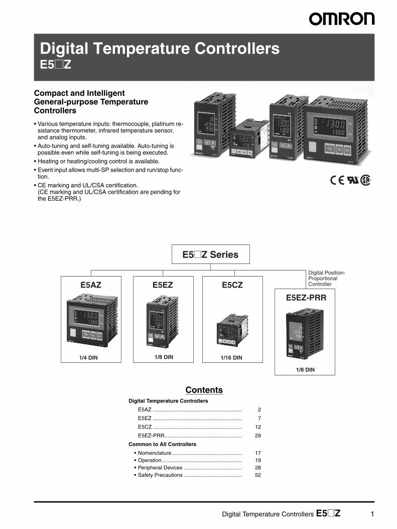
Compact and Intelligent General-purpose Temperature Controllers
• Various temperature inputs: thermocouple, platinum re-sistance thermometer, infrared temperature sensor, and analog inputs.
• Auto-tuning and self-tuning available. Auto-tuning is possible even while self-tuning is being executed.
• Heating or heating/cooling control is available.• Event input allows multi-SP selection and run/stop func-
tion.
• CE marking and UL/CSA certification.(CE marking and UL/CSA certification are pending for the E5EZ-PRR.)
Operating voltage range 85% to 110% of rated supply voltage
Power consumption 10 VA
Sensor input Thermocouple: K, J, T, E, L, U, N, R, S, BPlatinum resistance thermometer: Pt100, JPt100Infrared temperature sensor: 10 to 70°C, 60 to 120°C, 115 to 165°C, 140 to 260°CVoltage input: 0 to 50 mV
Control outputs Relay outputs SPST-NO, 250 VAC, 5 A (resistive load), electrical life: 100,000 operations
Voltage outputs 12 VDC +15%/−20% (PNP), max. load current: 40 mA, with short-circuit protection circuit
Current outputs 4 to 20 mA DC, load: 600 Ω max., resolution: approx. 2,600
Option board E53-AZM Expansion for E53-AZH and E53-AZ01 or E53-AZ03 or E53-AZB
Event input E53-AZB ON: 1 KΩ max.; OFF: 100 KΩ min.
Heater burnout detection E53-AZH Using CT to detect heater burnout
Digital Temperature Controllers E5AZ 5
Characteristics
Note 1: The indication accuracy of K thermocouples in the −200 to 1300°C range, T and N thermocouples at a temperature of −100°C or less,and U and L thermocouples at any temperature is ±2°C ±1 digit maximum. The indication accuracy of the B thermocouples at a temper-ature of 400°C max. is not specified. The indication accuracy of the R and S thermocouples at a temperature of 200°C max. is ±3°C ±1 digit maximum.
2: To fulfill the EN 61326 Class A standard for the E5@Z-@3@03, add a magnetic link (TDK: ZAT1730-0730) between the K3SC and theController.
3: Conditions: Ambient temperature: −10°C to 23°C to 55°C, Voltage range: −15% to +10% of rated voltage.
Indication accuracy Thermocouple: (±0.5% of indicated value or ±1°C, whichever is greater) ±1 digit max. (See note 1.)Platinum resistance thermometer: (±0.5% of indicated value or ±1°C, whichever is greater) ±1 digit max. Analog input: ±0.5% FS±1 digit max. CT input: ±5% FS±1 digit max.
Influence of temperature (See note 3.)
R, S, and B thermocouple inputs:(±1% of PV or ±10°C, whichever is greater) ±1 digit max.Other thermocouple inputs:(±1% of PV or ±4°C, whichever is greater) ±1 digit max.*±10°C for −100°C or less for K sensorsPlatinum resistance thermometer inputs:(±1% of PV or ±2°C, whichever is greater) ±1 digit max.Analog inputs:(±1% of FS) ±1 digit max.
Influence of voltage (See note 3.)
Hysteresis 0.1 to 999.9 EU (in units of 0.1 EU)
Proportional band (P) 0.1 to 999.9 EU (in units of 0.1 EU)
Integral time (I) 0 to 3999 s (in units of 1 s)
Derivative time (D) 0 to 3999 s (in units of 1 s)
Control period 1 to 99 s (in units of 1 s)
Manual reset value 0.0% to 100.0% (in units of 0.1%)
Alarm setting range −1999 to 9999 (decimal point position depends on input type)
Sampling period 500 ms
Insulation resistance 20 MΩ min. (at 500 VDC)
Dielectric strength 2,000 VAC, 50 or 60 Hz for 1min (between current-carrying terminals of different polarity)
Vibration resistance 10 to 55 Hz, 20 m/s2 for 10 min in X, Y and Z directions
Shock resistance 100 m/s2, 3 times each in 3 axes, 6 directions
Weight Approx. 310 g; accessories: approx. 100 g
Memory protection EEPROM (non-volatile memory) (number of write operations: 100,000)
EMC Enclosure Emission: EN 55011 (GB/T 6113.1,2) Group 1 Class AAC Mains Emission: EN 55011 (GB/T 6113.1,2) Group 1 Class A (See note 2.)ESD Immunity: IEC 61000-4-2 (GB/T 17626.2) 4 kV contact discharge (level 2)
Applicable standards UL 61010C-1, CSA C22.2 No.1010.1Conforms to EN 61326, EN 61010-1 (IEC 61010-1).
6 Digital Temperature Controllers E5AZ
DimensionsNote: All units are in millimeters unless otherwise indicated.
Wiring Terminals• The voltage output (control output) is not electrically insulated from the internal circuits. When using a grounding thermocouple, do not connect
the control output terminals to the ground. If the control output terminals are connected to the ground, errors will occur in the measured temper-ature values as a result of leakage current.
• Standard insulation is applied to the power supply I/O sections. If reinforced insulation is required, connect the input and output terminals to adevice without any exposed current-carrying parts or to a device with standard insulation suitable for the maximum operating voltage of thepower supply I/O section.
120
min
92 +
08 0
92 +
08 0
92 +08 0
7811.5
112
96
96
PV
SV
ALM1
ALM2
ALM3
HB
OUT1
OUT2
STOP
CMW
E5AZ
e
E5AZ
PV
SV
ALM1ALM2ALM3
HB
OUT1
OUT2STOP
CMW
Recommended panel thickness is 1 to 8 mm.
Group mounting is not possible in the verticadirection. (Maintain the specified mounting spacebetween Controllers when they are group mounted.)
l
When two or more Controllers are mounted, make sure that the surrounding temperature does not exceed the allowable operating temperaturespecified in the specifications.
Mounted separately Group Mounted(96 × No. of units −3.5) +1.0
0
2
3
4
5
6
7
8
9
10
11
2
3
4
5
6
7
8
9
10
11
12
13
14
15
16
AL3/OUT2
AL2
OUT1
B
A
B
−
+
−
+
12
13
14
15
16
17
18
19
20
21
22
TC Pt
AL1/HB
CT
EV1
EV2
RS-48512
13
14
B(+)
A(−)
RS-232C12
13
14
SD
RD
SG
600 Ω
Do not use
Input power supply
Alarm output, 250 VAC 2 A
(resistive load)
Voltage output, 12 VDC 40 mV
Current output, 4 to 20 mA DC
Relay output, 250 VAC 5 A(resistive load)
Analog input
100 to 240 VAC1 1
Event inputs
Heater burnout detection input
Digital Temperature Controllers E5EZ 7
Digital Temperature ControllersE5EZ
Next-generation Digital Temperature Controller
• Depth of only 78 mm.
• Various temperature inputs: thermocouple, platinum resistance thermometer, infrared temperature sensor, and analog inputs.
• Auto-tuning and self-tuning are available. Auto-tuning is possi-ble even while self-tuning is being executed.
• Heating or heating/cooling control is available.• Event input allows multi-SP selection and run/stop function.
• Modular output cards.• Time delay alarm function.• Communications function.
• CE marking and UL/CSA approval.
Refer to the "Safety Precautions" on page 52.
48 × 96 × 78 mm (W × H × D)
®
Model Number Structure
Model Number Legend
1. Output typeR: RelayQ: Voltage (for driving SSR)C: CurrentA: Output Unit can be mounted
2. Number of alarms3: Three alarms
3. Option 1Blank: Not availableH: Heater Burnout Alarm
4. Option 2Blank: Not available01: RS-232C02: RS-485B: 2 event inputs
Note: Options 1 and 2 are available when using an E53-AZM OptionBoard.
1 2 3 4E5EZ- @ 3 @ @
8 Digital Temperature Controllers E5EZ
Ordering Information List of Models
Output Modules
Option UnitsThe E5EZ provides optional functions when an E53-AZM Option Board is mounted along with the following Option Units.
Size Power supply voltage Number of alarm points Control outputs Model
1/8 DIN48 × 96 × 78 mm (W × H × D)
100 to 240 VAC 3 Relay E5EZ-R3
Voltage (for driving SSR)
E5EZ-Q3
Current E5EZ-C3
Additional control output E5EZ-A3
Type Model
Relay E53-AZR
Voltage E53-AZQ
Current E53-AZC
Functions Model
Option Board E53-AZM
Heater Burnout Alarm E53-AZH
Communications E53-AZ01
E53-AZ03
Event Input E53-AZB
Model E54-CT1 E54-CT3
Hole diameter 5.8 dia. 12.0 dia.
Power supply voltage 100 to 240 VAC, 50/60 Hz
Operating voltage range 85% to 110% of rated supply voltage
Power consumption 10 VA
Sensor input Thermocouple: K, J, T, E, L, U, N, R, S, BPlatinum resistance thermometer: Pt100, JPt100Infrared temperature sensor: 10 to 70°C, 60 to 120°C, 115 to 165°C, 140 to 260°CVoltage input: 0 to 50 mV
Control outputs Relay outputs SPST-NO, 250 VAC, 5 A (resistive load), electrical life: 100,000 operations
Voltage outputs 12 VDC +15%/−20% (PNP), max. load current: 40 mA, with short-circuit protection circuit
Current outputs 4 to 20 mA DC, load: 600 Ω max., resolution: approx. 2,600
Option board E53-AZM Expansion for E53-AZH and E53-AZ01 or E53-AZ03 or E53-AZB
Event input E53-AZB ON: 1 KΩ max.; OFF: 100 KΩ min.
Heater burnout detection E53-AZH Using CT to detect heater burnout
10 Digital Temperature Controllers E5EZ
Characteristics
Note 1: The indication accuracy of K thermocouples in the −200 to 1300°C range, T and N thermocouples at a temperature of −100°C or less,and U and L thermocouples at any temperature is ±2°C ±1 digit maximum. The indication accuracy of the B thermocouples at a temper-ature of 400°C max. is not specified. The indication accuracy of the R and S thermocouples at a temperature of 200°C max. is ±3°C ±1 digit maximum.
2: To fulfill the EN 61326 Class A standard for the E5@Z-@3@03, add a magnetic link (TDK: ZAT1730-0730) between the K3SC and theController.
3: Conditions: Ambient temperature: −10°C to 23°C to 55°C, Voltage range: −15% to +10% of rated voltage.
Indication accuracy Thermocouple: (±0.5% of indicated value or ±1°C, whichever is greater) ±1 digit max. (See note 1.)Platinum resistance thermometer: (±0.5% of indicated value or ±1°C, whichever is greater) ±1 digit max. Analog input: ±0.5% FS±1 digit max. CT input: ±5% FS±1 digit max.
Influence of temperature (See note 3.)
R, S, and B thermocouple inputs:(±1% of PV or ±10°C, whichever is greater) ±1 digit max.Other thermocouple inputs:(±1% of PV or ±4°C, whichever is greater) ±1 digit max.*±10°C for −100°C or less for K sensorsPlatinum resistance thermometer inputs:(±1% of PV or ±2°C, whichever is greater) ±1 digit max.Analog inputs:(±1% of FS) ±1 digit max.
Influence of voltage(See note 3.)
Hysteresis 0.1 to 999.9 EU (in units of 0.1 EU)
Proportional band (P) 0.1 to 999.9 EU (in units of 0.1 EU)
Integral time (I) 0 to 3999 s (in units of 1 s)
Derivative time (D) 0 to 3999 s (in units of 1 s)
Control period 1 to 99 s (in units of 1 s)
Manual reset value 0.0% to 100.0% (in units of 0.1%)
Alarm setting range −1999 to 9999 (decimal point position depends on input type)
Sampling period 500 ms
Insulation resistance 20 MΩ min. (at 500 VDC)
Dielectric strength 2,000 VAC, 50 or 60 Hz for 1min (between current-carrying terminals of different polarity)
Vibration resistance 10 to 55 Hz, 20 m/s2 for 10 min in X, Y and Z directions
Shock resistance 100 m/s2, 3 times each in 3 axes, 6 directions
Weight Approx. 260 g; accessories: approx. 100 g
Memory protection EEPROM (non-volatile memory) (number of write operations: 100,000)
EMC Enclosure Emission: EN 55011 (GB/T 6113.1,2) Group 1 Class AAC Mains Emission: EN 55011 (GB/T 6113.1,2) Group 1 Class A (See note 2.)ESD Immunity: IEC 61000-4-2 (GB/T 17626.2) 4 kV contact discharge (level 2)
Applicable standards UL 61010C-1, CSA C22.2 No.1010.1Conforms to EN 61326, EN 61010-1 (IEC 61010-1).
Digital Temperature Controllers E5EZ 11
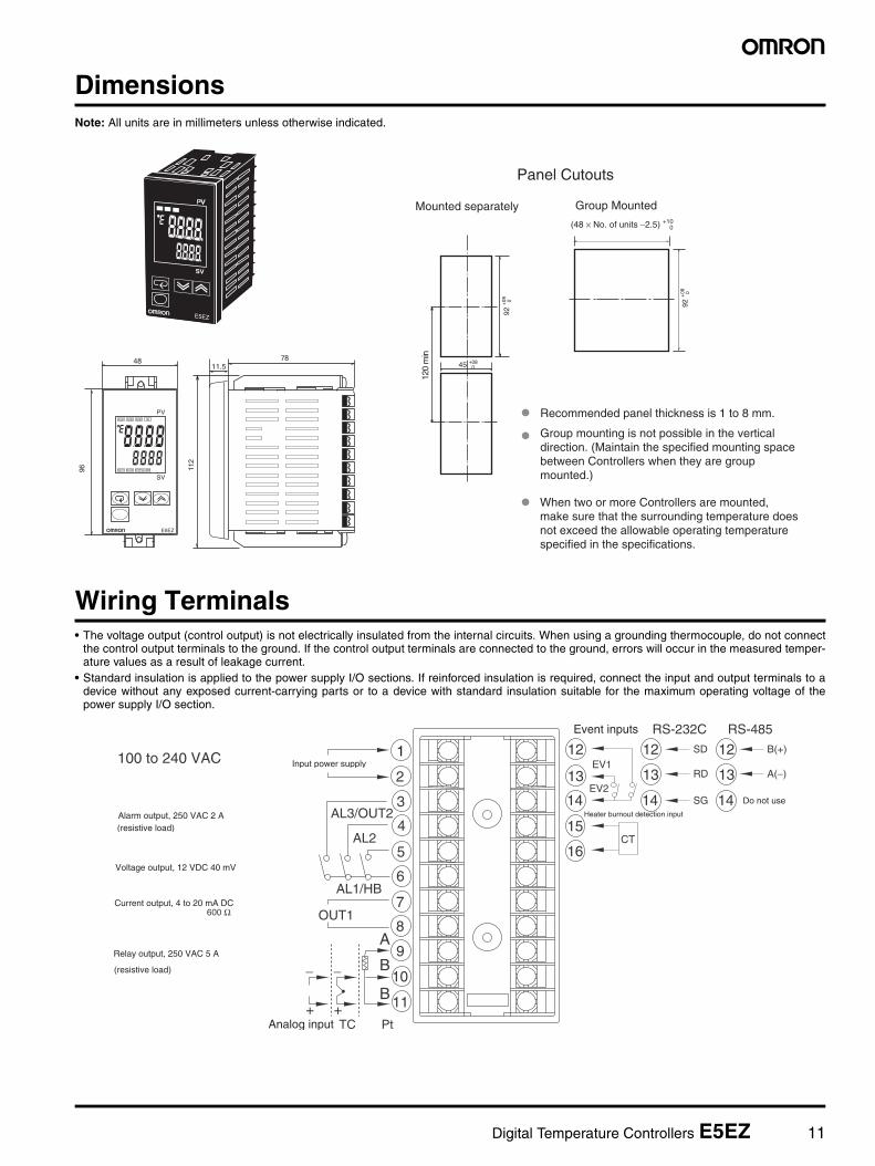
DimensionsNote: All units are in millimeters unless otherwise indicated.
Wiring Terminals• The voltage output (control output) is not electrically insulated from the internal circuits. When using a grounding thermocouple, do not connect
the control output terminals to the ground. If the control output terminals are connected to the ground, errors will occur in the measured temper-ature values as a result of leakage current.
• Standard insulation is applied to the power supply I/O sections. If reinforced insulation is required, connect the input and output terminals to adevice without any exposed current-carrying parts or to a device with standard insulation suitable for the maximum operating voltage of thepower supply I/O section.
120
min
92 +
08 0
92 +
08 0
45 +08 0
96
ALM1 ALM2 ALM3 HB
OUT1 OUT2 STOP CMW
e
E5EZ
78
112
Recommended panel thickness is 1 to 8 mm.
Group mounting is not possible in the verticaldirection. (Maintain the specified mounting spacebetween Controllers when they are groupmounted.)
Panel Cutouts
Mounted separately Group Mounted
(48 × No. of units −2.5) +10 0
11.548
PV
SV
When two or more Controllers are mounted,make sure that the surrounding temperature does not exceed the allowable operating temperaturespecified in the specifications.
100 to 240 VAC12
13
14
15
16
2
3
4
5
6
7
8
9
10
11
AL3/OUT2
AL2
OUT1
B
A
B
AL1/HB
CT
EV1
EV2
12
13
14
RS-232CSD
RD
SG
12
13
14
RS-485B(+)
A(−)
−
+TC Pt
−
+
600 Ω
Input power supply
Alarm output, 250 VAC 2 A(resistive load)
Voltage output, 12 VDC 40 mV
Current output, 4 to 20 mA DC
Relay output, 250 VAC 5 A
(resistive load)
Do not use
Analog input
1
Event inputs
Heater burnout detection input
12 Digital Temperature Controllers E5CZ
Digital Temperature ControllersE5CZ
Next-generation Digital Temperature Controller
• Depth of only 78 mm.• Various temperature inputs: thermocouple, platinum resistance
thermometer, infrared temperature sensor, and analog inputs.
• Auto-tuning and self-tuning are available. Auto-tuning is possi-ble even while self-tuning is being executed.
• Heating or heating/cooling control is available.
• Start/stop function.• CE marking and UL/CSA approval. • Models with optional functions and current output added to the
series.
Refer to the "Safety Precautions" on page 52.
48 × 48 × 78 mm (W × H × D)
®
Model Number Structure
Model Number Legend
1. Output typeR: RelayQ: Voltage (for driving SSR)C: Current
2. Number of alarms2: Two alarms
3. Option UnitBlank: Not availableM: Option Unit can be mounted
4. Power supply voltageBlank: 100 to 240 VACD: 24 VAC/VDC
Ordering Information
List of Models
Option UnitsThe E5CZ-@2M provides communications or event input functionality when one of the following Option Units is mounted.
1 2 3 4E5CZ- @ 2 @ @
Size Power supply voltage
Number of alarm points
Control output Option Unit Model
1/16 DIN48 × 48 × 78 mm (W × H × D)
100 to 240 VAC 2 Relay Not Available E5CZ-R2
Voltage for driving SSR Not Available E5CZ-Q2
Relay Available E5CZ-R2M
Voltage for driving SSR Available E5CZ-Q2M
Current Available E5CZ-C2M
24 VAC/VDC 2 Relay Available E5CZ-R2MD
Voltage for driving SSR Available E5CZ-Q2MD
Current Available E5CZ-C2MD
Functions Model
Communications Heater burnout E53-CNH03N
Communications E53-CN03N
Heater burnout Event inputs E53-CNHBN
Event inputs E53-CNBN
Digital Temperature Controllers E5CZ 13
Accessories (Order Separately)
Current Transformers (CTs)
Specifications
Ratings
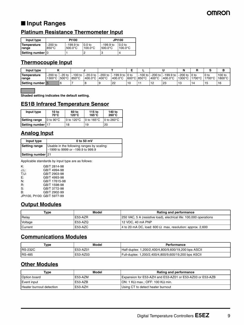
Input Ranges
Platinum Resistance Thermometer Input
Thermocouple Input
Shaded setting indicates the default setting.
ES1B Infrared Temperature Sensor
Model E54-CT1 E54-CT3
Hole diameter 5.8 dia. 12.0 dia.
Power supply voltage 100 to 240 VAC, 50/60 Hz 24 VAC/VDC, 50/60 Hz
Operating voltage range 85% to 110% of rated supply voltage
Power consumption 7 VA 5 VA, 3 W
Sensor input Thermocouple: K, J, T, E, L, U, N, R, S, BPlatinum resistance thermometer: Pt100, JPt100Infrared temperature sensor: 10 to 70°C, 60 to 120°C, 115 to 165°C, 140 to 260°CVoltage input: 0 to 50 mV
Control output Relay output SPST-NO, 250 VAC, 3 A (resistive load), electrical life: 100,000 operations
Voltage output 12 VDC +15%/−20% (PNP), max. load current: 21 mA, with short-circuit protection circuit
Current output 4 to 20 mA DC, load: 600 Ω max., resolution: approx. 2,600
Note 1. The indication accuracy of K thermocouples in the −200 to 1300°C range, T and N thermocouples at a temperature of −100°C max. andU and L thermocouples at any temperature is ±2°C ±1 digit maximum. The indication accuracy of the B thermocouples at a temperatureof 400°C max. is not specified.The indication accuracy of the R and S thermocouples at a temperature of 200°C max. is ±3°C ±1 digit maximum.
2. Conditions: Ambient temperature: −10°C to 23°C to 55°C, Voltage range: −15% to +10% of rated voltage.3. When using the E53-CN03N or E53-CNBN Option Unit with the E5CZ-C2M or E5CZ-C2M to satisfy the Class A limit for the radiated in-
terference field strength test, always connect a ZCAT2235-1030 Clamp Filter (manufactured by TDK) to the power line of the TemperatureController.
Input type 0 to 50 mV
Setting range Usable in the following ranges by scaling: −1999 to 9999 or −199.9 to 999.9
Setting number 21
Indication accuracy Thermocouple: (±0.5% of indicated value or ±1°C, whichever is greater) ±1 digit max. (See note 1.) Platinum resistance thermometer: (±0.5% of indicated value or ±1°C, whichever is greater) ±1 digit max. Analog input: ±0.5% FS±1 digit max. CT input: ±5% FS±1 digit max.
Influence of temperature (See note 2.)
R, S, and B thermocouple inputs:(±1% of PV or ±10°C, whichever is greater) ±1 digit max.Other thermocouple inputs:(±1% of PV or ±4°C, whichever is greater) ±1 digit max.*±10°C for −100°C or less for K sensorsPlatinum resistance thermometer inputs:(±1% of PV or ±2°C, whichever is greater) ±1 digit max.Analog inputs:(±1% of FS) ±1 digit max.
Influence of voltage(See note 2.)
Hysteresis 0.1 to 999.9 EU (in units of 0.1 EU)
Proportional band (P) 0.1 to 999.9 EU (in units of 0.1 EU)
Integral time (I) 0 to 3999 s (in units of 1 s)
Derivative time (D) 0 to 3999 s (in units of 1 s)
Control period 1 to 99 s (in units of 1 s)
Manual reset value 0.0% to 100.0% (in units of 0.1%)
Alarm setting range −1999 to 9999 (decimal point position depends on input type)
Sampling period 500 ms
Insulation resistance 20 MΩ min. (at 500 VDC)
Dielectric strength 2,000 VAC, 50 or 60 Hz for 1min (between current-carrying terminals of different polarity)
Vibration resistance 10 to 55 Hz, 20 m/s2 for 10 min in X, Y and Z directions
Shock resistance 100 m/s2, 3 times each in 3 axes, 6 directions
Weight Approx. 150 g
Memory protection EEPROM (non-volatile memory) (number of write operations: 100,000)
EMC Enclosure Emission: EN 55011 (GB/T 6113.1,2) Group 1 Class AAC Mains Emission: EN 55011 (GB/T 6113.1,2) Group 1 Class AESD Immunity: IEC 61000-4-2 (GB/T 17626.2) 4 kV contact discharge (level 2)
Applicable standards UL 61010C-1, CSA C22.2 No.1010.1Conforms to EN 61326, EN 61010-1 (IEC 61010-1).
Digital Temperature Controllers E5CZ 15
DimensionsNote: All units are in millimeters unless otherwise indicated.
PV
SV
E5CZ
e
48
60 m
in
45 +
0.6
0
102
93
78
58 48.8
48.8
6
ALM1
ALM2
OUT1
OUT2
STOP
E5CZ
P V
S V
ALM1ALM2
OUT1OUT2
STOP
Panel Cutouts
Mounted separately Group Mounted
(48 × No. of units −2.5) +1.0 0
Recommended panel thickness is 1 to 8 mm.
45 +
0.6
0
45 +0.6 0
When two or more Controllers are mounted, make sure that the surrounding temperature does not exceed the allowable operating temperature specified in the specifications.
Group mounting is not possible in the vertical direction. (Maintain the specified mounting space between Controllers when they are group mounted.)
E54-CT3 Accessories• Contact
30
21
155.8 dia.
25 3
40
10.5
2.8
7.5
10
Two, 3.5 dia.
40@
30
12 dia.
9
2.36 dia.
15
30
Two, M3 holes (depth: 4)
Approx. 3 dia.
18
(22)
Approx. 6 dia.
PlugContact
Lead wire
Current Transformers
E54-CT1
E54-CT3
Connection Example
• Plug
16 Digital Temperature Controllers E5CZ
Wiring Terminals• The voltage output (control output) is not electrically insulated from the internal circuits. When using a grounded thermocouple, do not connect
the control output terminals to the ground. If the control output terminals are connected to the ground, errors will occur in the measured temper-ature values as a result of leakage current.
12 VDC 21 mAControl output 1
Analog input Input power supply
Alarm output
Two input power supplies are available: 100 to 240 VAC or 24 VDC.
Contact Inputs ON: 1 kΩ max., OFF: 100 kΩ min.Non-Contact Inputs ON: residual voltage of 1.5 V max. OFF: leakage current of 0.1 mA max.
Heater Burnout Alarm
Maximum heater current: 50 A ACInput current indication accuracy: ±5% FS ±1 digit max.Heater burnout alarm setting range: 0.1 to 49.9 A, in 0.1 A increments
Digital Temperature Controllers E5AZ/E5EZ/E5CZ 17
Nomenclature
E5AZ
E5EZ
PV
SV
ALM1
ALM2
ALM3
HB
OUT1
OUT2
STOP
CMW
E5AZ
Temperature UnitOperation Indicators No. 1 Display
No. 2 Display
Up Key
Down Key
Level Key
Mode Key
Level + Mode Keys
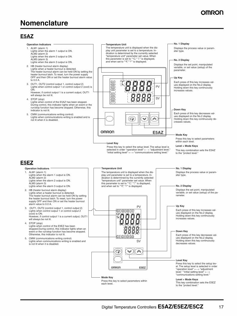
1. ALM1 (alarm 1) Lights when the alarm 1 output is ON. ALM2 (alarm 2) Lights when the alarm 2 output is ON. ALM3 (alarm 3) Lights when the alarm 3 output is ON.
2. HB (heater burnout alarm display) Lights when a heater burnout is detected. The heater burnout alarm can be held ON by setting the heater burnout latch. To reset, turn the power supply OFF and then ON or set the heater burnout alarm value to 0.0 A.
3. OUT1, OUT2 (control output 1, control output 2) Lights when control output 1 or control output 2 (cool) is ON. However, if control output 1 is a current output, OUT1 will always be not lit.
4. STOP (stop) Lights when control of the E5AZ has been stopped. During control, this indicator lights when an event or the run/stop function has become stopped. Otherwise, this indicator is not lit.
5. CMW (communications writing control) Lights when communications writing is enabled and is not lit when it is disabled.
The temperature unit is displayed when the dis-play unit parameter is set to a temperature. In-dication is determined by the currently selected "temperature unit" parameter set value. When this parameter is set to "°C," "c" is displayed, and when set to "°F," "f" is displayed.
Displays the process value or param-eter type.
Displays the set point, manipulated variable, or set value (setup) of the parameter.
Each press of this key increases val-ues displayed on the No.2 display. Holding down this key continuously increases values.
Each press of this key decreases val-ues displayed on the No.2 display. Holding down this key continuously de-creases values.
This key combination sets the E5AZ to the "protect level."
Press this key to select parameters within each level.
Press this key to select the setup level. The setup level is selected in order "operation level" ←→ "adjustment level," "initial setting level" ←→ "communications setting level."
PV
SV
ALM1 ALM2 ALM3 HB
OUT1 OUT2 STOP CMW
E5EZ
Temperature UnitOperation Indicators No. 1 Display
No. 2 Display
Up Key
Down Key
Level Key
Level + Mode KeysMode Key
1. ALM1 (alarm 1) Lights when the alarm 1 output is ON. ALM2 (alarm 2) Lights when the alarm 2 output is ON. ALM3 (alarm 3) Lights when the alarm 3 output is ON.
2. HB (heater burnout alarm display) Lights when a heater burnout is detected. The heater burnout alarm can be held ON by setting the heater burnout latch. To reset, turn the power supply OFF and then ON or set the heater burnout alarm value to 0.0 A.
3. OUT1, OUT2 (control output 1, control output 2) Lights when control output 1 or control output 2 (cool) is ON. However, if control output 1 is a current output, OUT1 will always be not lit.
4. STOP (stop) Lights when control of the E5EZ has been stopped.During control, this indicator lights when an event or the run/stop function has become stopped. Otherwise, this indicator is not lit.
5. CMW (communications writing control) Lights when communications writing is enabled and is not lit when it is disabled.
The temperature unit is displayed when the dis-play unit parameter is set to a temperature. In-dication is determined by the currently selected "temperature unit" parameter set value. When this parameter is set to "°C," "c" is displayed, and when set to "°F," "f" is displayed.
Displays the process value or param-eter type.
Displays the set point, manipulated variable, or set value (setup) of the pa-rameter.
Each press of this key increases val-ues displayed on the No.2 display. Holding down this key continuously increases values.
Each press of this key decreases val-ues displayed on the No.2 display. Holding down this key continuously decreases values.
This key combination sets the E5EZ to the "protect level."
Press this key to select the setup lev-el. The setup level is selected in order "operation level" ←→ "adjustment level," "initial setting level" ←→ "communications setting level."
Press this key to select parameters within each level.
18 Digital Temperature Controllers E5AZ/E5EZ/E5CZ
E5CZ
PV
SV
ALM1
ALM2
OUT1
HB
OUT2
STOP
CMW
E5CZ
Temperature UnitOperation Indicators No. 1 Display
Displays the process value or parameter type.
No. 2 Display
Up Key
Down Key
Mode Key
Level KeyLevel + Mode Keys
1. ALM1 (alarm 1) Lights when the alarm 1 output is
ON. ALM2 (alarm 2) Lights when the alarm 2 output is
ON.2. HB (heater burnout alarm display) Lights when a heater burnout is de-
tected. The heater burnout alarm can be
held ON by setting the heater burn-out latch. To reset, turn the power supply OFF and then ON or set the heater burnout alarm value to 0.0 A.
Lights when control output 1 or con-trol output 2 (cool) is ON.
However, if control output 1 is a cur-rent output, OUT1 will always be not lit.
4. STP (stop) Lights when control of the E5CZ has
been stopped. During control, this indicator lights
when an event or the run/stop func-tion has become stopped. Otherwise, this indicator is not lit.
5. CMW (communications writing con-trol)
Lights when communications writing is enabled and is not lit when it is dis-abled.
The temperature unit is displayed when the dis-play unit parameter is set to a temperature. Indi-cation is determined by the currently selected "temperature unit" parameter set value. When this parameter is set to "°C," "c" is displayed, and when set to "°F," "f" is displayed.
Displays the set point, manipulated variable, or set value (setup) of the parameter.
Each press of this key increases values displayed on the No.2 display. Holding down this key continuously increases values.
Each press of this key decreases values displayed on the No.2 display. Holding down this key continuously decreases values.
This key combination sets the E5CZ to the "protect level."
Press this key to select parameters within each level.
Press this key to select the setup level. The setup level is selected in order "operation level" ←→ "adjustment level," "initial setting level" ←→ "communications setting level."
Digital Temperature Controllers E5AZ/E5EZ/E5CZ 19
Operation
PID Control Using Autotuning
Changing Set Values
Display
E5CZNo. 1 display
No. 2 display
Setup procedure
Power ON
Self-tuning
Set alarm values
Start operation
Power ON
Operation level
In PID control
To cancel ST
Press key for at least one second.
Press key for less than one second.Adjustment level
Operation level
To execute AT
Press key for less than one second.
During run
Start operation
Operation level
Check alarm type
Set the set point
Set operation status
Typical Example
AT execution
Input type 4
Initial setting level
After AT execution.
During AT execution.
PV/SP
After AT execution.
During AT execution.
Changing Parameters
E5EZ
No. 1 display
No. 2 display
E5AZ
No. 1 display
No. 2 display
indicates that there is a pa-rameter. Keep on pressing the mode key until the de-sired parameter is selected.
Use the or keys to change the set value displayed in the setup menu.
While AT is being executed, SP will flash.
Input type: 4 T thermocouple −200 to 400°CControl method: PID control
ST (self-tuning): OFFCalculate PID constants by AT (auto-tuning).
Alarm type: 2 upper limit
Alarm value 1: 30°C (For setting deviation)
Set point: 150°C
Process value/ set point
Press key for at least three seconds.
Set input specifications
Set control specifications
Check control period
Press keys to select input type.
Press keys to select PID control.
Press keys to set ST to OFF.
Check the control period.
Check alarm type.
Control period (heat) (unit: seconds)
Alarm 1 type 2 (upper-limit alarm)
Recommended set-tings: 20 seconds for the relay output and 2 seconds for the SSR output.
Press keys to set set point to "150°C."
PV/ SP 150
Execute AT (auto-tuning).
Set to on for execut-ing AT and to off for stopping AT.
Make sure that set point is "150°C."
PV/ SP150
Make sure that control is running.
Press keys to set alarm value to "30°C."
Alarm value 1 30
Control stops.
When set to ON, self-tuning operates.
20 Digital Temperature Controllers E5AZ/E5EZ/E5CZ
Specification Setting after Turning ON Power
Outline of Operation Procedures
Key OperationIn the following descriptions, all the parameters are introduced in the display sequence. Some parameters may not be displayed depending on theprotect settings and operation conditions.
Description of Each Level
Operation LevelThis level is displayed when you turn the power ON. You can move tothe protect level, initial setting level and adjustment level from thislevel.
Normally, select this level during operation. During operation, theprocess value, set point and manipulated variable can be monitored,and the alarm value and upper- and lower-limit alarms can be moni-tored and modified.
Adjustment LevelTo select this level, press the key once for less than one second.
This level is for entering set values and offset values for control. Thislevel contains parameters for setting the set values, AT (auto-tuning),communications writing enable/disable, hysteresis, multi-SP, inputshift values, heater burnout alarm (HBA) and PID constants. You canmove to the top parameter of the operation level or initial setting levelfrom here.
Initial Setting LevelTo select this level, press the key for at least three seconds in theoperation level. This level is for specifying the input type, selectingthe control method, control period, setting direct/reverse action andalarm type. You can move to the advanced function setting level orcommunications setting level from this initial setting level. To return to
the operation level, press the key for at least one second. Tomove to the communications setting level, press the key once forless than one second.
Protect LevelTo select this level, simultaneously press the and M keys for atleast 3 seconds. This level is to prevent unwanted or accidental mod-ification of parameters. Protected levels will not be displayed, and sothe parameters in that level cannot be modified.
Communications Setting LevelTo select this level, press the key once for less than one second inthe initial setting level. When the communications function is used,set the communications conditions in this level. Communicating witha personal computer (host computer) allows set points to be readand written, and manipulated variables to be monitored.
Advanced Function Setting LevelTo select this level, you must enter the password (“-169”) in the initialsetting level.
You can move only to the calibration level from this level.
This level is for setting the automatic return of display mode, MV lim-iter, event input assignment, standby sequence, alarm hysteresis, ST(self-tune) and to move to the user calibration level.
Power ON
Operation level Adjustment level
+ key 1 second min.
Control stops.
Protect levelInitial setting level
Control in progress
Control stopped
Level change
key 1 second min.
+ key 3 seconds min.
+ key Display flashes when key pressed.
key
key Less than 1 second
key 1 second min.
key 3 seconds min.
Display flashes when key held down for more than 1 second.
Communica-tions setting level key
Less than 1 second
Password input set value "−169"
Advanced function setting level
The time taken to move to the protect level can be adjusted by changing the "Move to protect level time" setting.
Note: Of these levels, the initial setting level, communications set-ting level, advanced function setting level and calibration level can be used only when control has stopped. Note that control is stopped when these four levels are selected. When switched back to the operation level from one of these levels, control will start.
Digital Temperature Controllers E5AZ/E5EZ/E5CZ 21
Specification Setting after Turning ON Power
Initial Setting LevelThis level is used for setting basic specifications of the TemperatureController. Using this level, set the input type for selecting the input tobe connected such as the thermocouple or platinum resistance ther-mometer and set the range of set point and the alarm mode.
The move from the operation level to the initial setting level, press key for three seconds or more.
The initial setting level is not displayed when “initial/communicationsprotection” is set to “2.” This initial setting level can be used when“initial setting/communications protection” is set to “0” or “1.”
The “scaling upper limit,” “scaling lower limit,” and “decimal point”parameters are displayed when an analog voltage input is selectedas the input type.
To return to the operation level, press the key for longer than onesecond.
* Not displayed as default setting.
Power ON
Operation level Adjustment level
Less than 1 second
1 second min.
Less than 1 second
Control stops.
1 second min.
Protect level
key+
1 second min.key
key
key
key
keykey+
key+
Control in progress
Control stopped
Level change
3 seconds min.
Initial setting level
Communica-tions setting level
Password input set value "−169"
Advanced function setting level
Display flashes when key pressed.
3 seconds min.
The time taken to move to the protect level can be adjusted by changing the "Move to protect lev-el time" setting.
Initial setting level
Input type
Scaling upper limit
Scaling lower limit
Decimal point
SP upper limit
SP lower limit
PID ON/OFF
ST
Control period (heating)
Control period (cooling)
Direct/reverse operation
Alarm 1 type
Alarm 2 type
(PID control)
Set the pulse output cycle.
(Displayed when initial setting/communications protection is set to 0.)
For analog input
Temperature unit
Standard or heating/ cooling
Alarm output type
(PID control) (Heating/cooling setting)
Alarm 3 type
Select the alarm mode. (Models with alarm function)
Move to advanced function setting level
22 Digital Temperature Controllers E5AZ/E5EZ/E5CZ
Input TypeWhen selecting the input type, follow the specifications listed in the following table.
Note: The initial setting is 5: −200 to 850°C/−300 to 2300°F.
Specifications Set Value Input Temperature Range
Platinum resistance thermometer input Pt100 0 −200 to 850 (°C)/−300 to 1500 (°F)
1 −199.9 to 500.0 (°C)/−199.9 to 900.0 (°F)
2 0.0 to 100.0 (°C)/0.0 to 210.0 (°F)
JPt100 3 −199.9 to 500.0 (°C)/−199.9 to 900.0 (°F)
4 0.0 to 100.0 (°C)/0.0 to 210.0 (°F)
Thermocouple input K 5 −200 to 1300 (°C)/−300 to 2300 (°F)
6 −20.0 to 500.0 (°C)/0.0 to 900.0 (°F)
J 7 −100 to 850 (°C)/−100 to 1500 (°F)
8 −20.0 to 400.0 (°C)/0.0 to 750.0 (°F)
T 9 −200 to 400 (°C)/−300 to 700 (°F)
22 −199.9 to 400.0 (°C)/199.9 to 700.0 (°F)
E 10 0 to 600 (°C)/0 to 1100 (°F)
L 11 −100 to 850 (°C)/−100 to 1500 (°F)
U 12 −200 to 400 (°C)/−300 to 2300 (°F)
23 −199.9 to 400.0 (°C)/199.9 to 700.0 (°F)
N 13 −200 to 1300 (°C)/−300 to 2300 (°F)
R 14 0 to 1700 (°C)/0 to 3000 (°F)
S 15 0 to 1700 (°C)/0 to 3000 (°F)
B 16 100 to 1800 (°C)/300 to 3200 (°F)
Non-contact Temperature Sensor (ES1B)
10 to 70°C 17 0 to 90 (°C)/0 to 190 (°F)
60 to 120°C 18 0 to 120 (°C)/0 to 240 (°F)
115 to 165°C 19 0 to 165 (°C)/0 to 320 (°F)
160 to 260°C 20 0 to 260 (°C)/0 to 500 (°F)
Analog input 0 to 50 mV 21 One of the following ranges depending on the results of scaling: 1999 to 9999, 199.9 to 999.9
Digital Temperature Controllers E5AZ/E5EZ/E5CZ 23
Alarm TypesSelect the alarm type from the 12 types listed in the following table.
Note 1: With set values 1, 4 and 5, the upper and lower limit valuescan be set independently for each alarm type, and are ex-pressed as “L” and “H.” Following operations are for cases when an alarm set pointis “X” or negative.
2: Set value: 1, Upper- and lower-limit alarm
3: Set value: 4, Upper- and lower-limit range
4: Set value: 5, Upper- and lower-limit with standby sequence
5: Set value: 5, Upper- and lower-limit with standby sequencealarm. Always OFF when the upper-limit and lower-limit hys-teresis overlaps.Set the alarm types for alarm 1 and alarm 2 independently inthe initial setting level. The default setting is 2 (upper limit).With the E5AZ/E5EZ, perform settings similarly for alarm 3.
Set Value Alarm Type Alarm Output Operation
When X is positive When X is negative
0 Alarm function OFF Output OFF
1 (See note 1.) Upper- and lower-limit (deviation) (See note 2.)
2 Upper-limit (deviation)
3 Lower-limit (deviation)
4 (See note 1.) Upper- and lower-limit range (deviation) (See note 3.)
5 (See note 1.) Upper- and lower-limit with standby se-quence (deviation)
(See note 4.)
6 Upper-limit with standby sequence (de-viation)
7 Lower-limit with standby sequence (de-viation)
8 Absolute-value upper-limit
9 Absolute-value lower-limit
10 Absolute-value upper-limit with standby sequence
11 Absolute-value lower-limit with standby sequence
(See note 5.)
=
=
Case 1 Case 2 Case 3 (Always ON)
=
=
L H
Case 1 Case 2 Case 3 (Always OFF)
Case 1 Case 2Example
Same as for the upper- and lower-limit alarm. However, when the upper-limit and lower-limit hysteresis overlaps: Always OFF
0°C/°F
Example: When the alarm is set ON at 110°C/°F or higher.
Alarm value Alarm value
(For alarm types 1 to 7) The alarm value is set as a deviation from the set point.
When an alarm type other than the absolute-value alarm is selected (For alarm types 8 to 11)
The alarm value is set as an absolute value from the alarm value of 0°C/F.
When the absolute-value alarm is selected
Set point 100°C/°F
24 Digital Temperature Controllers E5AZ/E5EZ/E5CZ
ParametersParameters related to setting items for each level are marked inboxes in the flowcharts and brief descriptions are given as required.At the end of each setting item, press the mode key to return to thebeginning of each level.
Control stops.
Initial setting level
Less than 1 s
Power ON
Operation level
Protect level
Control in progress
Control stopped
Adjustment level
Level change
Less than 1 s
key
key
key
key
key
+ key
+ key
+ key
+ key
1 s min. 3 s min.
1 s min.
Display flashes when key held down for more than 1 s.
Communica-tions setting level
Password input set value "−169"
Advanced function setting level
Display flashes when key pressed.
3 s min.
The time taken to move to the protect level can be adjusted by changing the "Move to protect level time" setting.
1 s min.
Display
E5CZNo. 1 display
No. 2 display
E5EZ
No. 1 display
No. 2 display
E5AZ
No. 1 display
No. 2 display
key 1 s min.
Advanced Function Setting Level
Note: To select advanced function setting level, you must enter the password ("−169") in the initial setting level.
Parameter initialization
Alarm 2 hysteresis
Alarm 2 open in alarm
Alarm 1 hysteresis
Alarm 1 open in alarm
Multi-SP uses
Event input assignment 2
Event input assignment 1
Number of multi-SP usesSelect 2 or 4.
Heater burnout detection
MV upper limit
ST stable range
Heater burnout hysteresis
Heater burnout latchLatch after heater burnout detection
SP ramp set valueRate of change during ramp
Resets to the default value.
Limitations to MV
For setting deviation.
Alarm 3 hysteresis
Alarm 3 open in alarm
Standby sequence reset method
MV lower limit
Input setting: Multi-SP/RUN/STOP
Restarting condition after clearing standby
ON/OFF setting of alarm output 1
ON/OFF setting of alarm output 2
ON/OFF setting of alarm output 3
α2-PID parameter
Alarm 1 ON delay
Alarm 2 ON delay
Alarm 3 ON delay
Move to protect level time
Input error output
Cold junction compensating method
MB command logic switching
Input digital filter
Additional PV displayDisplayed first in the operation level
MV display
Automatic return of display mode
Alarm ON/OFF delays
Alarm 1 OFF delay
Alarm 2 OFF delay
Alarm 3 OFF delay
Digital Temperature Controllers E5AZ/E5EZ/E5CZ 25
Note: These diagrams show all the parameters that may be displayed. Depending on the specifications of the model used, there may be someparameters that are not displayed.
Input ShiftAll points in the sensor range are shifted by the value set as the tem-perature input shift value.
Example
Power ON
Operation LevelInitial Setting Level Adjustment Levelkey 3 s min.
key 1 s min.
key Less than 1 s
key Less than 1 s
c: °C
f: °F
Input type
Scaling upper limit
Decimal point
Temperature unit
SP upper limit
PID ON/OFF
Standard or heating/cooling
Control period (heating)
Alarm 1 type
Direct/reverse operationControls the MV in responseincreases or decreases in the PV.
Alarm 2 type
Limit the set point.
Select the control system.
ST
Control period (cooling)OUT2
Number of displayed digits
SP lower limit
Scaling lower limit
Alarm 3 type
OUT1
For analog input
Set the pulse output cycle.
Select the alarm mode.
Move to advanced function setting level
Note: This parameter is not displayed as a default set-ting. To move to the advanced function setting level, change the initial setting/communications protection setting from 1 to 0. (See page 31.)
Process value
Process value/set point
Multi-SP set point setting
SP ramp monitor
Heater current value monitor
Run/stop
Alarm value 1
Alarm value 2
MV monitor (cooling)
MV monitor (heating)
Alarm value 3
Add in the "additional PV display" parameter.
Upper-limit alarm value 1
Set either of these parameters.
Lower-limit alarm value 1
Set either of these parameters.
Upper-limit alarm value 2
Lower-limit alarm value 2
Set either of these parameters.
Upper-limit alarm value 3
Lower-limit alarm value 3
The displays for parameters which can be switched (i.e., parameters other than simply numerical ones) show the contents of those parameters.
P
I
D
Hysteresis (heating)
AT execute/cancel
Communications writing
SP 0
SP 1
Temperature input shift 1-point shift
2-point shift (see note)
Proportional band
PID settings
Cooling coefficient
Dead band
Manual reset value
SP 2
SP 3
Derivative time
Integral time
Set hysteresis.Hysteresis (cooling)
Heater current value monitor
Heater burnout detection
HBA function
SP used by multi-SP
Upper-limit temperature input
Lower-limit temperature input
Used in heating and cooling control
Clear the offset during stabilization of P or PD control.
The 2-point shift setting is only possible when the input type is an infrared temperature sensor.
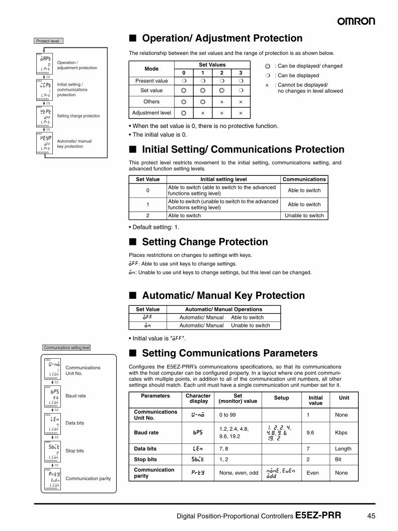
Operation/Adjustment ProtectionThe following table shows the relationship between set values andthe range of protection.
When this parameter is set to “0,” parameters are not protected.
Initial Setting/Communications ProtectionThis protect level restricts movement to the initial setting level, com-munications setting level and advanced function setting level.
Default setting: 1: Move to other levels possibleX: Move to other levels not possible
Setting Change ProtectionThis protect level protects setup from being changed by operatingthe keys on the front panel.
ON Setup cannot be changed by key operation. (The protect level, can be changed.)
Operation/adjustment protection
Initial setting/communications protection
Setting change protection
Restricts displaying and modifying menus in operation, adjustment, and manual control levels.
This protect level restricts movement to the initial setting, communications setting, and advanced function setting levels.
Protects changes to setups by operating the front panel keys.
Default setting: 0
: Can be displayed and changed: Can be displayedX : Cannot be displayed and move to other levels not possible
Digital Temperature Controllers E5AZ/E5EZ/E5CZ 27
Communications Setting LevelSet the E5AZ/E5EZ/E5CZ communications specifications in the communications setting level. For setting communications parameters, use theE5AZ/E5EZ/E5CZ panel. The communications parameters and their settings are listed in the following table.
Note: The highlighted values indicate default settings.
Before executing communications with the E5AZ/E5EZ/E5CZ, setthe communications unit No., baud rate, etc., through key operationsas described below. As for other operations, refer to relevant Opera-tion Manual.
1. Press the key for at least three seconds in the “operationlevel.” The level moves to the “initial setting level.”
2. Press the key for less than one second. The “initial settinglevel” moves to the “communications setting level.”
3. Pressing the key advances the parameters as shown in thefollowing figure.
4. Press the or keys to change the parameter setups.
Note: On the E5AZ/E5EZ, the key is the key.
Set each communications parameter to match those of the communi-cating personal computer.
Communications Unit No. (u-no)When communicating with the host computer, the unit number mustbe set in each Temperature Controller so that the host computer canidentify each Temperature Controller. The number can be set in arange from 0 to 99 in increments of 1. The default setting is 1. Whenusing more than one Unit, be careful not to use the same numbertwice. Duplicate settings will cause malfunction. This value becomesvalid when the power is turned OFF and ON again.
Baud Rate (bps)Use this parameter to set the speed of communications with the hostcomputer. It can be set to one of the following values; 1.2 (1200 bps),2.4 (2400 bps), 4.8 (4800 bps), 9.6 (9600 bps), and 19.2(19200 bps).This setting becomes valid when the power is turned OFF and ONagain.
Data Bits (len)Use this parameter to change the communications data bit length to7 bits or 8 bits.
Stop Bits (sbit)Use this parameter to change the communications stop bit to 1 or 2.
Communications parity (prty)Use this parameter to set the communications parity to None, Even,or Odd.
TroubleshootingWhen an error occurs, an error code will be displayed on the No. 1 display. Check the contents of an error and take appropriate countermeasures.
Note 1. If the input is within the range for which control is possible but outside the displayable range (−1999 (−199.9) to 9999 (999.9)), will bedisplayed if the value is less than −1999 (−199.9), and will be displayed if it is greater than 9999 (999.9). Control output and alarmoutput will operate normally for either of these displays. Refer to the relevant User’s Manual for details on the ranges for which control ispossible.
2. These errors are displayed only when the Controller is set to display the present value or the present value and the set value. They are notdisplayed in other statuses.
Parameter Displayed characters Set (monitor) value Set value
Communications unit No. u-no 0 to 99
Baud rate bps 1.2/2.4/4.8/9.6/19.2 (kbps)
Data bits len 7/8 (bit)
Stop bits sbit 1/2
Parity prty None, even, odd
0.1 to 99
1.2/2.4/4.8/9.6/19.2
7/8 (bit)
1/2 (bit)
none/euen/odd
Baud rate
Data bits
Stop bits
Communications parity
Communications unit No.
No.1 display Contents Countermeasure Output status
Control output Alarm output
s.err (S. Err) Input error (See note.) Check that the input wiring is correct, that there is no discon-nection or short-circuit, and that the input type is correct. (Thermocouple input short-circuits cannot be detected.)
OFF Handled as ab-normally high temperature
A/D converter error(See note.)
After noting the error, reset the power. If the display does not change, replacement is necessary. If the error is removed, it is possible that the original error was caused by noise. Check that there are no possible sources of noise.
OFF OFF
e111 (E111) Memory error Reset the power. If the display does not change, replacement is necessary. If the error is removed, it is possible that the original error was caused by noise. Check that there are no possible sources of noise.
OFF OFF
h.err (H. Err) HB error (See note.) OFF OFF
((((
))))
28 Digital Temperature Controllers E5AZ/E5EZ/E5CZ
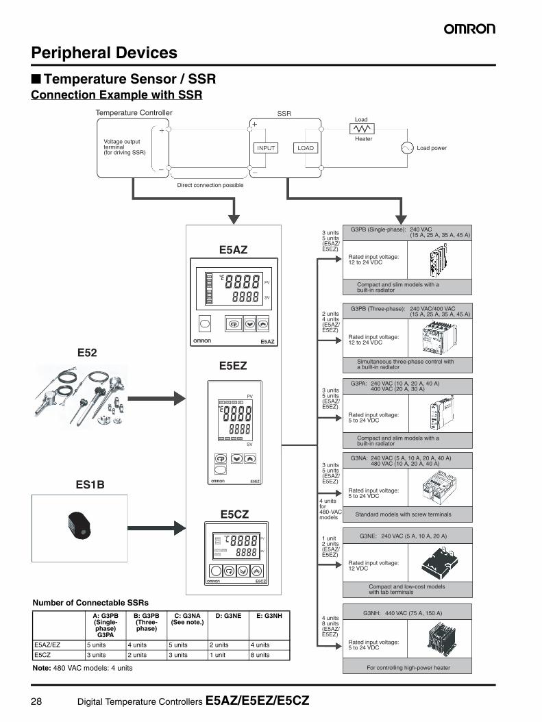
Peripheral Devices
Temperature Sensor / SSRConnection Example with SSR
PV
SV
ALM1
ALM2
ALM3
HB
OUT1
OUT2
STOP
CMW
E5AZ
PV
SV
ALM1 ALM2 ALM3 HB
OUT1 OUT2 STOP CMW
E5EZ
PV
SV
ALM1
ALM2
OUT1
OUT2
STOP
E5CZ
Temperature ControllerLoad
Heater
Load power
Direct connection possible
E5EZE52
ES1B
E5CZ
E5AZ
For controlling high-power heater
G3NH: 440 VAC (75 A, 150 A)
Standard models with screw terminals
G3NE: 240 VAC (5 A, 10 A, 20 A)
3 units 5 units (E5AZ/ E5EZ)
G3PB (Single-phase): 240 VAC (15 A, 25 A, 35 A, 45 A)
Rated input voltage: 12 to 24 VDC
2 units 4 units (E5AZ/ E5EZ)
3 units 5 units (E5AZ/ E5EZ)
Compact and slim models with a built-in radiator
G3PB (Three-phase): 240 VAC/400 VAC (15 A, 25 A, 35 A, 45 A)
Rated input voltage: 12 to 24 VDC
Simultaneous three-phase control with a built-in radiator
G3PA: 240 VAC (10 A, 20 A, 40 A) 400 VAC (20 A, 30 A)
Rated input voltage: 5 to 24 VDC
Compact and slim models with a built-in radiator
3 units 5 units (E5AZ/ E5EZ)
4 units for 480-VAC models
1 unit 2 units (E5AZ/ E5EZ)
G3NA: 240 VAC (5 A, 10 A, 20 A, 40 A) 480 VAC (10 A, 20 A, 40 A)
Rated input voltage: 5 to 24 VDC
Rated input voltage: 12 VDC
Compact and low-cost models with tab terminals
4 units 8 units (E5AZ/ E5EZ)
Rated input voltage: 5 to 24 VDC
Voltage output terminal (for driving SSR)
Number of Connectable SSRs
Note: 480 VAC models: 4 units
A: G3PB (Single-phase) G3PA
B: G3PB (Three-phase)
C: G3NA(See note.)
D: G3NE E: G3NH
E5AZ/EZ 5 units 4 units 5 units 2 units 4 units
E5CZ 3 units 2 units 3 units 1 unit 8 units
Digital Position-Proportional Controllers E5EZ-PRR 29
Digital Position-Proportional ControllersE5EZ-PRR
A position proportional control model for the E5Z-PRR series• Just 78mm depth• All types of input: temperature input type, analog (current, voltage) input
type• Makes use of high-visibility LCD, with three lines of 4-digit display, for
simplicity and clarity
• 3 lines of display to observe PV/ SV/ MV (percentage of valve's opening), clearly displaying the state of control (operations)
• Event input enables the selection of multi configurations as well as a start/ stop function
• Alarm delay function• Communications function
• Able to choose floating control or closed control. In floating control, position proportional control can be realized without a potentiometer
• Equipped with a manual output function (equipped with an automatic/ manual key)
Model Number Structure Model Number Legend
Ordering Information
Accessories (Order Separately)Unit Label
Size Power SupplyVoltage Input Type Control
MethodNumber of
alarm pointsCommunication
Function Event Input Model
1/8DIN
48×96×78
(W×H×D)
100 to 240 VAC
TemperatureInput Type
Valve Control 2
NoneNone E5EZ-PRR2T
2 points E5EZ-PRR2BT
RS-232CNone
E5EZ-PRR201T
RS-485 E5EZ-PRR203T
Analog(Current, Voltage)
Input Type
NoneNone E5EZ-PRR2L
2 points E5EZ-PRR2BL
RS-232CNone
E5EZ-PRR201L
RS-485 E5EZ-PRR203L
Model Y92S-L1
Refer to the "Safety Precautions" on page 52.
1 2 3 4 5 6
1. Control method P: Valve control 2. Control output 1
R: Relay (OPEN)3. Control output 2
R: Relay (CLOSE)
4. Alarm output2: 2 alarm outputs
5. OptionBlanks: Not available01: RS-232C03: RS-485B: 2 event inputs
6. Input TypeT: Temperature L: Analog input (current, voltage)
30 Digital Position-Proportional Controllers E5EZ-PRR
Platinum resistance thermometer Thermocouple Analog input
Tem
pera
ture
ran
ge (˚
C)
Usable in the following ranges by scaling:-1999 to 9999 or -199.9 to 999.9
Digital Position-Proportional Controllers E5EZ-PRR 31
Specifications
Ratings
Communications Specifications
Power supply voltage 100 to 240VAC, 50/60Hz
Operating voltage range 85% to 110% of the designated source voltage
Power consumption 10VA (10W)
Sensor input Temperature input typeThermocouple: K, J, T, E, L, U, N, R, S,B Platinum Resistance Thermometer: Pt100,JPt100Infrared temperature sensor: 10 to 70°C, 60 to 120°C, 115 to 165°C, 140 to 260°CAnalog signal input: 0 to 50mVAnalog (current, voltage) input type Current input: 4 to 20mA,0 to 20mA Voltage input: 1 to 5V, 0 to 5V, 0 to 10V
Communications method (see note 1) RS-485 (two-wire, half duplex)/RS-232C
Synchronization method Start-stop synchronization
Baud rate 1,200/2,400/4,800/9,600/19,200bps
Transmission code ASCII
Data bit length (see note 2) 7 or 8 bits
Stop bit length (see note 2) 1 or 2 bits
Error detection Vertical parity (none, even, odd)Block check character (BCC)
Flow control Not available
Interface RS-485/RS-232C
Retry function Not available
32 Digital Position-Proportional Controllers E5EZ-PRR
Specifications
Characteristics
Note 1: The indication accuracy of K thermocouples in the -200 to 1300°C range, T and N thermocouples at a temperature of -100°C max., andU and L thermocouples at any temperature is ±2°C ±1 digit maximum. The indication accuracy of the B thermocouple at a temperature of400°C max. is not specified. The indication accuracy of the R and S thermocouples at a temperature of 200°C max. is ±3°C ±1 digit max.
2: For E5EZ-PRR03-model products, in order to satisfy the conduction and emission specifications of EN61326CLASSA, a magnetic ring(TDK:ZAT1730-0730) should be added to the communications line between the K3SC unit and the controller.
Indication accuracy Thermocouple: (displayed value ±0.5 % or ±1°C, whichever is largest) ±1 digit max. (see note 1)Platinum Resistance Thermometer:(displayed value ±0.5 % or ±1°C, whichever is largest) ±1 digit max.Analog Input: ±0.5% FS ±1 digit max.Potentiometer Input: ±5% FS ±1 digit max.
Influence of temperature (See note 2.)
R, S, and B thermocouple inputs:(±1% of PV or ±10°C, whichever is greater) ±1 digit max.Other thermocouple inputs:(±1% of PV or ±4°C, whichever is greater) ±1 digit max.*±10°C for -100°C or less for K sensorsPlatinum resistance thermometer inputs:(±1% of PV or ±2°C, whichever is greater) ±1 digit max.Analog inputs:(±1% of FS) ±1 digit max.
Influence of voltage(See note 2.)
Proportional band ( P ) 0.1 to 999.9°C (unit: 0.1 EU)
Integral time (I) 0 to 3999 s (in units of 1s) With floating control, 1 to 3999 s
Derivative time (D) 0 to 3999 s (in units of 1s)
Control period 1 to 99 s (in units of 1s)
Manual reset value -10.0% to 110.0% (in units of 0.1%)
Alarm settings range -1999 to 9999 (decimal point position depends on input type)
Pending standards UL61010C-1,CSA C22.2 No.1010.1 meets the requirements of EN61326,EN61010-1(IEC61010-1)
Digital Position-Proportional Controllers E5EZ-PRR 33
DimensionsNote:All figures are in mm, unless otherwise stated.
Main Unit
• Package Content
• Dimensions of Panel's Grooves
• Unit Labels (Order Separately)
1 Temperature Gauge2 Metallic Components For Installation1 Operating Manual1 Quality Certificate
1 Temperature Gauge2 Metallic Components For Installation1 Operating Manual1 Quality Certificate
During removal, please use a screwdriver to remove the clips on the top and bottom of the front covering panel, and then remove the temperature gauge's front panel.
During removal, please use a screwdriver to remove the clips on the top and bottom of the front covering panel, and then remove the temperature gauge's front panel.
Independent Installation (Unit: mm)
Simultaneous Multiple Installations (Unit: mm)
(48 Number of Units - 2.5)45
92
92
abov
e 12
0
During installation, please insert a temperature gauge into the grooves on the panel (thickness of 1 to 8 mm), and insert the metallic components for installation into the fixing hooks at the bottom and the top of the rear cover.
Please ensure that the screws to metallic components are even and locked.
When doing multiple installations, please ensure that the temperature gauge remains within the specified temperature range.
Y92S-L1 Type
48
11.8
34 Digital Position-Proportional Controllers E5EZ-PRR
Wiring Terminals• Standard insulation is applied to the temperature gauge's I/O sections. If reinforced insulation is required, connect the input and
output terminals to a device without any exposed current-carrying parts, or to a device with standard insulation suitable for the maximum operation voltage of the power supply I/O section.
• For E5EZ-PRR03-model products, in order to satisfy the conduction and emission specifications of EN61326CLASSA, a mag-netic ring (TDK: ZAT1730-0730) should be added to the communications line between the K3SC unit and the controller.
E5EZ-PRR
Alarm Output 1
Alarm Output 2
B
B
A
mA
DO NOT USE
USEDO NOT
50/60Hz
Potentiometer
CommunicationsCommunications
OPEN
10
Pt
11
6
8
7
9
100 to 240 VAC1
2
3
4
5
12 EV1
Event Input
SD
RD
SG
RS232C RS485B( )
A( )
DO NOT
USE
13
14
12
13
14 14
13
12
TC
22
21
20
CLOSE
WIPE
DO NOTUSE
Analog Input
EV2
V
Control Output 1 (OPEN Output)
Control Output 2 (CLOSE Output)
Digital Position-Proportional Controllers E5EZ-PRR 35
Nomenclature
E5EZ-PRR
MANU
A/M
PV
SV
MV
AM
No. 1 Display
Operation Indicator
Temperature Unit
Mode Key
Level Key
Down Key
Up Key
No. 2 Display
No. 3 Display
Automatic/ Manual Key
Press this level key to select parameters.
The temperature unit is displayed when the display unit parameter is set to temperature.The value selected for the temperature units parameter determines the unit displayed.When set to ˚C, C is displayed, and when set to ˚F, F is displayed.
1. ALM1 (Alarm 1): Illuminated when Alarm 1 output
is on.
ALM2 (Alarm 2): Illuminated when Alarm 2 output
is on.
2. OUT1, OUT2 Control Output 1(OPEN) and
2(CLOSE)
Illuminated when control output 1 and/ or control
output 2 are on.
3. STOP (Stop)
Illuminated when operations are stopped.
Illuminated during controls when time input or the
start/ stop function is stopped. Not illuminated in
any other cases.
4. CMW (Communications Writing Control)
Illuminated when communications writing is
enabled. Not illuminated in any other cases.
5. MANU (Manual Control)
Illuminated during manual mode. Not illuminated in
any other cases.
Displays the process value or the designated data type.Fully illuminated for approximately one second upon start-up.
Displays setting values, reading values, and input values. Fully illuminated for approximately one second upon start-up.
When valve opening display is on, it displays the percentage of the valve’s opening. No display when valve opening display is switched off.
Every time that this key is pressed, the figure shown in No. 2 Display will decrease. Changes in the displayed value accelerate as the time that the key is pressed decreases. In manual mode, pressing the D key will switch on control output 2 (closed side output).
This automatic/ manual key makes the switch between automatic mode and manual mode. When this key is pressed for at least 1 second (unrelated to the time at which the key is released), the unit will switch modes.
Every time that this key is pressed, the figure shown in No. 2 Display will increase. Changes in the displayed value accelerate as the time that the button is pressed decreases. In manual mode, pressing the U key will switch on control output 1 (open side output).
Press this key to select the setting level.The sequence of setting level selection is:operation level Adjustment level,Initial input level Communications setting level.
36 Digital Position-Proportional Controllers E5EZ-PRR
OperationIn the past, sensor input types, alarm types, and control time for controllers were set using the DIP switch. Now, these hardware settings canbe performed with the parameters in the setting level. The and M keys are used to switch between setting levels, with the level determinedby the amount of time the key is pressed. Two examples of typical setup procedures follow.
• Typical ExamplesChanges in Set Values
• Typical Example 1
L
intl
onof
in-t
0
M M
M
in-h
100
in-l
0
intl
onof
25c
0
Changes in Datal.ini
l.ini
l.ini
l.ini
l.ini
0100.
When there are multi parameters, press down on the mode key until all necessary parameters have been selected.
Changes can be made to data on displays with the UD key.
25c
0
M
alt1
2
in-t 5
M
al-1c
20
20
100
25c
100
M
M
M
r-5 run
Setup Steps
Initial setting level
Operation level
Connect the power supply
Connect the power supply
Set the inputtype
Set the alarm type
Set the alarm value
Begin operations Begin operations
Alarm value1
While running
Process value/ set value/percentage of valve opening
While stopped stop
Check alarm type
Check input type 5Input type
1Alarm
2Alarm
Operation level
Operation level
Initial setting level
Control starts
Control stops
L
L
l.ini
l.ini
l.ini
l.ini
run
100. .0
100. .0
C
Input Type : 5K thermocouple -200˚C to 1300˚C
Control Method : PID Control
Alarm 1 Type : Upper limit of 2 (deviation)
Alarm Value 1 : 20˚C (deviation)
Set value : 100˚C
Press the key for at least 3 seconds
Press the key for at least 1 second
Press the DU key, and designate the set value as 100˚C
Press the DU key, and set the alarm value as 20˚C
Confirm that control is operating
Process value/ set value/percentage of valve opening
Digital Position-Proportional Controllers E5EZ-PRR 37
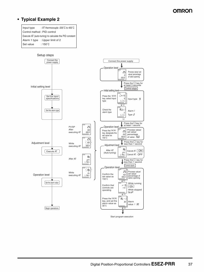
• Typical Example 2
M
at
off
25c
150
25c
150
al-1c
30
r-5run
M
M
M
25
100
at
off
25
100
at
on
25c
0
in-t
9
M
alt1
2
Setup steps
Initial setting level
Adjustment level
Operation level
Connect thepower supply
Set the inputspecifications
Set the alarm type
Execute AT
While executing AT
While executing AT
After AT(Auto-tuning)
Set the alarm value
Begin operations
PV/SPAfter executing AT
After AT
Start program execution
Connect the power supply
Operation level
Initial setting level
Operation level
Adjustment level
Operation level
Check thealarm type
Alarmvalue 1 30
While running
While stoppedstop
150
9Input type
Alarm1
2Type
Control stops
L
Control starts
L
L
Execute AT:
Cancel AT:
l.ini
l.ini
Process value/set value/percentage ofvalve opening
run
ON
OFFl. adj
l. adj
l. adj100. .0
100. .0
100. .0
100. .0
100. .0
Input type : 9T thermocouple -200˚C to 400˚C
Control method : PID control
Execute AT (auto-tuning) to calculate the PID constant
Alarm 1 type : Upper limit of 2
Set value : 150˚C
Process value/ set value/ percentage of valve opening
Press the key for at least 3 seconds
Press the key for at least 1 second
Press the key for less than 1 second
LPress the key for less than 1 second
Press the DU key, select input type
Press the DU key, designate the set value as 150˚C
Process value/set value/ percentageof valve
Confirm the set value as 150˚C
Confirm that controls are operating
Press the DU key, and set the alarm value as 30˚C
38 Digital Position-Proportional Controllers E5EZ-PRR
Setting Level Configuration and Panel Key OperationsParameters are split into groups, which are referred to as levels. Each of the set values (set items) in these levels are referred to as parameters.E5EZ-PRR parameters are categorized into the following 7 levels:
Note1:When returning from the initial setting lever to the operation level, theoperation level's initial value will be displayed.
2:When returning from the protect level to the operation level, theoperation level's initial value will be displayed.
∗: Set the initial/ communications protection parameter in protect level to 0, in order to activate the advanced function setting level.: Indicates items that can be set. In these cases, the initial setting level, communications setting level, and advanced function setting levelcan only be used when controls are stopped. Please take note of the fact that when any one of these three levels is selected, the controller'soutput will be stopped.With the exception of operation level, the present level will be on display. No. 3 Display will show the following when switching between setvalues:
Press the L key for at least 1 s; display will flash.Press the L key for at least 3 s.
Press the L key for at least 3 s while
Press L key for at least 1 s.
a-m is displayed.
Press the L key for at least 1 s; display will flash.
Press the L key for at least 1 s.
Press L key for at least 1 s.
Digital Position-Proportional Controllers E5EZ-PRR 39
Descriptions of Each Level• Protect Level • In order to switch to this level, it is necessary to press the and
M keys simultaneously for at least 3 seconds. This level is used to prevent unnecessary or accidental revisions to the parameters.The protected level is not displayed, so that no changes can be made to parameters within this level.
• Operation Level • Once a power supply is connected, this level is displayed. It is possible to switch from this level to protect level, initial setting lev-el, and adjustment level.
• During regular operations, this level is selected. It is possible to view process value and MV during operations, as well as viewing and revising set values, alarm values, and upper and lower limits.
• Adjustment Level • In order to switch to this level, press the key for less than 1 second.
• Input in this level is used in controlling set values and shifted val-ues. This level contains parameters used in setting up AT (auto-tuning), communications writing enabling/ disabling, hysteresis, multi-SP, input shift, and PID constants. It is possible to switch from this level to the peak parameters in the initial setting level, protect level, or operation level.
• Manual Control Level • Pressing the A key for at least 1 second in operations/ adjust-ment level will place you in manual mode and bring you to man-ual control level. During manual operations, nothing besides process value/ set value/ percentage of valve opening (manual MV) can be displayed. In manual control, with process value/ set value/ percentage of valve opening (manual MV) displayed, pressing the A key for at least 1 second will move you into auto-matic mode and switch you to the operation level, displaying op-eration level's initial data. In this mode, it is possible to perform MV manual operations.
• Initial Setting Level • To switch to this level, it is necessary to press the key in op-eration level or adjustment level for at least 3 seconds. One sec-ond later, the PV display will flash. This level is used for designating input types, selecting control methods and control times, as well as setting direct/ reverse operations and alarm types. From this level, it is possible to switch to the advanced function setting level or communications setting level. Press the
key for at least 1 second to return to operation level. Press the key for less than 1 second to switch to the communications
setting level.
• Advanced Function Setting Level • In order to activate the advanced function setting level, set protect level's initial setting/ communications protection to 0, and then in-put the password (-169) in the input initial setting level.
• It is possible to switch from this level to the initial setting level.• This level is used to set the display mode, event input assign-
ment, standby sequence, alarm hysteresis, and alarm delay.
• Communications Setting Level • To switch to this level, press the key in the initial setting level for less than 1 second. When using the communications function, the conditions of communication are to be set in this level. Com-munications with a personal computer (host computer) allows set values to be read and written, and manipulated variables to be monitored.
L
L
L
L
L
L
40 Digital Position-Proportional Controllers E5EZ-PRR
Setting the Type of InputTypes of input include thermocouple, platinum resistance thermometer, infrared temperature sensor,and analog inputs. Please set your input type in accordance with the sensor to be used. Product spec-ifications also include multi input types, such as thermocouples/ plastic resistance thermometers, andanalog input types, resulting in differences between set values. Please confirm the model that you areusing.
Table of Input Types
• Initial value of "5"
• Initial value of "0"
Input Type Name Set value Set Range of Temperature Input
PlatinumResistanceThermometer
Pt100
0 -200 to 850 (°C) / -300 to 1500 (°F)
1 -199.9 to 500.0 (°C) / -199.9 to 900.0 (°F)
2 0.0 to 100.0 (°C) / 0.0 to 210.0 (°F)
JPt1003 -199.9 to 500.0 (°C) / -199.9 to 900.0 (°F)
4 0.0 to 100.0 (°C) / 0.0 to 210.0 (°F)
Thermocouple
K5 -200 to 1300 (°C) / -300 to 2300 (°F)
6 -20.0 to 500.0 (°C) / 0.0 to 900.0 (°F)
J7 -100 to 850 (°C) / -100 to 1500 (°F)
8 -20.0 to 400.0 (°C) / 0.0 to 750.0 (°F)
T9 -200 to 400 (°C) / -300 to 700 (°F)
22 -199.9 to 500.0 (°C) / -199.9 to 700.0 (°F)
E 10 0 to 600 (°C) / 0 to 1100 (°F)
L 11 -100 to 850 (°C) / -100 to 1500 (°F)
U12 -200 to 400 (°C) / -300 to 700 (°F)
23 -199.9 to 500.0 (°C) / -199.9 to 700 (°F)
N 13 -200 to 1300 (°C) / -300 to 2300 (°F)
R 14 0 to 1700 (°C) / 0 to 3000 (°F)
S 15 0 to 1700 (°C) / 0 to 3000 (°F)
B 16 100 to 1800 (°C) / 300 to 3200 (°F)
Infraredtemperaturesensor,ES1B
10°C to 70°C 17 0 to 90 (°C) / 0 to 190 (°F)
60°C to 120°C 18 0 to 120 (°C) / 0 to 240 (°F)
115°C to 165°C 19 0 to 165 (°C) / 0 to 320 (°F)
140°C to 260°C 20 0 to 260 (°C) / 0 to 500 (°F)
Analog Input 0 to 50 mV 21 The scaling usage range is either-1999 to 9999 or -199.9 to 999.9
Input Type Specifica-tions Set value Set Range of Input
Ana
log
Inpu
t Typ
e CurrentInput
4 to 20mA 0 Use the following scales based on the range of measurements:-19999 to 9999-199.9 to 999.9-19.99 to 99.99-1.999 to 9.999
0 to 20mA 1
VoltageInput
1 to 5V 2
0 to 5V 3
0 to 10V 4
in-t
5
l.ini
Input Types 5
Digital Position-Proportional Controllers E5EZ-PRR 41
Alarm Types• The conditions of alarm output are jointly determined by Alarm Type and Alarm Hysteresis.
• Below is an explanation of the alarm type, alarm value, upper alarm limit, and lower alarm limit parameters.
0 Alarm function OFF Output OFF
1 See note 1.
Upper-and lower-limits See note 2.
Upper limits2
3 Lower limits
4 See note 1. Upper-and lower-limits See note 3.
Upper-and lower-limit with standby sequence5
See note 1. See note 4.(See note 5)
Upper-limit with standby sequence6
Lower-limit with standby sequence7
Absolute-value upper-limits8
Absolute-value lower-limits9
Absolute-value upper-limit with standby sequence10
Absolute-value lower-limit with standby sequence11
ONOFF
L H
SP
XONOFF
SP
XONOFF
SP
X
SP
ONOFF
XONOFF
SP
XONOFF
SP
XONOFF
SP
XONOFF
SP
ONOFF
L H
SP
ONOFF
L H
SP
XONOFF
0
XONOFF
0
XONOFF
0
XONOFF
0
XONOFF
0
XONOFF
0
XONOFF
0
XONOFF
0
SP
ONOFF
X
L H SP SP L H L SP H
H LSP
SP H L
H< 0.L >0|H| < |L|
H> 0.L <0|H| > |L|
Case 1 Case 2 Case 3 (Always ON)
H< 0.L >0|H| < |L|
H> 0.L <0|H| > |L|
H< 0.L <0
L H SP SP L H L SP H
H L SP
SP H L
3. Set value: 4, Upper-and lower-limit range
2. Set value: 1, Upper-and lower-limit
Case 1 Case 2 Case 3 (Always OFF)
4. Set value: 5, Upper-and lower-limit with standby sequence
*for the upper and lower alarm limits above
Example of case 1 and case 2: in case 3, the alarm will always be OFF.
5. Set value: 5, Upper-and lower-limit with standby sequence
Alarm1
Type 2
Alarm output operationSet values Type
When X is positive When X is negative
Note:1. Upper and lower limits can be set independently for each alarm point, represented by L and H. The set values are 1, 4, and 5.
- In case 1 and 2, if there are any overlaps in the upper and lower limits for hysteresis, the alarm will always be OFF.
If there are any overlaps in the upper and lower limits for hysteresis, the alarm will always be OFF.
There are alarm types 1 to 2 (initial setting level), and settings should be made independently for each alarm.The initial value is 2: upper limit.
alt1
2
l.ini
42 Digital Position-Proportional Controllers E5EZ-PRR
ParametersParameters related to setting items for each level are marked in boxes in the following flowchart and brief descriptions are given as required.After finishing each setting, press the mode key to return to the beginning of each level.
∗ The amount of time that a key must be pressed can be changed under protect level switching time (advanced function setting level).
to select the advanced function setting level, you must input the password (-169) in the initial setting level.
Digital Position-Proportional Controllers E5EZ-PRR 43
Parameters• In each level, if you press the mode key on the final parameter, you will return to the parameter at the top of the level.
Advanced function setting level
init
off
en-m
1
Parameter initialization
none
stop
Event input assignment 1
Event input assignment 2
ospu
off
rest
a
al1n
n-o
Multi-SP uses on off
Alarm 1 open in alarm
Alarm 1 hysteresis
al2n
n-o
Alarm 2 open in alarm
Alarm 2 hysteresis
alh1
02
alh2
02
C
C
a1lt
offAlarm 1 latch
a2lt
off
Alarm 2 latch
Alarm 2OFF delay
Additional MVfor stop/error
a2of
0
Decimal point
is Celsius, and is Fahrenheit
Temperature unit ˚C / ˚F
Input typein-t
5
l.ini
Scaling upper limit
Scaling lower limitin-l
0
in-h
100
Initial setting level
dp
0
l.
l.
l.
prlt
3Move to protect level time
Input error output
cjc
on
Cold junction compensation method
MB command logic switching
Alarm 1ON delay
Alarm 2 ON delay
sero
off
a1on
0
off
a2on
0
Alarm 1OFF delay
a1of
0
l.
l.
l.
l.
l.
l.
l.
on
oanl
on
p-db
0
l.
l.
l.
alfa
0.65
l.
l.
l.
l.
l.
l.
l.
l.
l.
l.
l.
l.
off
Process value dead band
Valve opening display
Manual MVLimits in effect
l.ini
l.ini
l.ini
d-u
c
sl-h
1300
sl-l
-200
SP upper limit
SP lower limit
Direct / reverse operationDirect operation: on-dReverse operation: or-r
Alarm 1
alt2
2Alarm 2
Closed / floatingFloating: flotClosed: clos
Electro-mechanical calibrationElectro-mechanical calibration: onCancel: off
alt1
2
clfl
flot
calb
off
Travel timemot
30
l.ini
l.ini
l.ini
l.ini
l.ini
l.ini
l.ini
l.ini
l.ini
0
Input digital filter Set the time constant, with a unit of s
α2 PID parameters
Additional process value display First display off in operation leveloff
inf
00
l.
l.
ret
offl.
SP alarm output 1activation status
SP alarm output 2activation status
Activate alarm latch
Only used in analoginput settings
Limit the set point
Select alarm mode
C
C
C
Select the number of multi-SP used, with 2 or 4 as the designated value
Multi-value setting and stop/run input
Standby sequence reset methodConditions for resetting following the cancellation of a standby sequence
Switch to advanced function setting levelTo switch to the advanced function setting level, the initial setting/ communications protection parameters must be set to 0.
Automatic return of display modePressing a key on the operation panel automatically returns to operation level
Setting the alarm output’s ON delay/ OFF delay
44 Digital Position-Proportional Controllers E5EZ-PRR
Stopped MVHold: holdOpen: openClose: close
PV error MVHold: holdOpen: openClose: close
sprt
off
ol-h
ol-l
SP ramp set value
MV upper limit
MV lower limit
Position’s proportional dead band
oc-hOpen/ close hysteresis
db
20
0.8
Adjustment level
at
off
l.adj l.adj
l.adj
l.adj
l.adj
l.adj
l.adj
l.adj
cmwt
off
Execute / cancelAT adjustmentAT on: onAT off: off
Communications writingEnabled: onDisabled: off
sp-0
0
sp-1
0
sp-2
0
SP 0
SP 1
SP 2
SP 3
in5
00Temperature input shift values
Proportional band
sp-3
0
in5l
00
in5h
00
p
80
Integral time (Unit: seconds)
Derivative time (Unit: seconds)
d
40
i
233
al1h
0
al1l
0
Upper-limit alarm value 1
Lower-limit alarm value 1
al-2
0
al2h
0
al2l
0
Alarm value 2
Upper-limit alarm value 2
Lower-limit alarm value 2
Process value
Multi-SP set point setting
SP ramp set point
25
m-sp
0
sp-m
0
Run/ stopRun: runStop: stop
Alarm value 1
Set either of these parameters
Set either these parameters
SP used byMulti-SP
MV limit value
1 point shift
2 point shift
PID settings
al-1
0
Operation level
Process value/ set point/ valve open percentage
25
0
0100. l.adj
l.adj
l.adj
l.adj
l.adj
l.adj
l.adj
l.adj
l.adj
l.adj
l.adj
100.0
0.0
C
C
C C
C
C
C
C
C
C
C
C
C
C
C
C
C
C
The "add process value display" parameter must be on.
Upper-limit temperature shift(When using a Infrared temperature sensor)
Lower-limit temperature shift(When using a Infrared temperature sensor)
Digital Position-Proportional Controllers E5EZ-PRR 45
Operation/ Adjustment ProtectionThe relationship between the set values and the range of protection is as shown below.
• When the set value is 0, there is no protective function.• The initial value is 0.
Initial Setting/ Communications ProtectionThis protect level restricts movement to the initial setting, communications setting, andadvanced function setting levels.
• Default setting: 1.
Setting Change ProtectionPlaces restrictions on changes to settings with keys.
off: Able to use unit keys to change settings.
on: Unable to use unit keys to change settings, but this level can be changed.
Automatic/ Manual Key Protection
• Initial value is "off".
Setting Communications ParametersConfigures the E5EZ-PRR's communications specifications, so that its communicationswith the host computer can be configured properly. In a layout where one point communi-cates with multiple points, in addition to all of the communication unit numbers, all othersettings should match. Each unit must have a single communication unit number set for it.
ModeSet Values : Can be displayed/ changed
: Can be displayed
× : Cannot be displayed/ no changes in level allowed
0 1 2 3
Present value
Set value
Others × ×
Adjustment level × × ×
Set Value Initial setting level Communications
0 Able to switch (able to switch to the advanced functions setting level) Able to switch
1 Able to switch (unable to switch to the advanced functions setting level) Able to switch
2 Able to switch Unable to switch
Set Value Automatic/ Manual Operations
off Automatic/ Manual Able to switch
on Automatic/ Manual Unable to switch
Parameters Character display
Set(monitor) value
Setup Initialvalue
Unit
CommunicationsUnit No. u-no 0 to 99 1 None
Baud rate bps1.2, 2.4, 4.8,9.6, 19.2
1. 2, 2. 4,4. 8, 9. 619. 2
9.6 Kbps
Data bits len 7, 8 7 Length
Stop bits sbit 1, 2 2 Bit
Communicationparity prty None, even, odd none, even
oddEven None
oapt
0
icpt
1
wtpt
off
keyp
off
Protect level
Operation / adjustment protection
Initial setting / communications protection
Setting change protection
Automatic/ manual key protection
l.prt
l.prt
l.prt
l.prt
u-no
1
len
7
sbit
2
Communications setting level
Communications Unit No.
Baud rate
Data bits
Stop bits
Communication parity
bps
9 6
l.com
l.com
l.com
l.com
l.com
46 Digital Position-Proportional Controllers E5EZ-PRR
Trouble shootingWhen an error occurs, the main display alternately shows an error signal andthe current item for display.
This section explains how to inspect an error signal, as well as corresponding rectification measures.
• Meaning The figure inputted has exceeded the designated input range (the designatedrange is between -1999 (-199.9) to 9999 (999.9)).
• Rectification Measures Check to make sure that the input line has not been connected incorrectly,unplugged, a short-circuit, or is incompatible with this input type.
If there are no problems with the line type or the connection, power off and then restart the unit. If the display remains unchanged, it will be necessary to change the E5EZ-PRR. If the display is recovered, the root of the problem may have been that noise from the energy flow was affecting the control system. Check for any such noise.
• Operations with Errors The control output will be determined according to the designated value forerror MV.
The alarm output function will be the same as it is when the upper limit iscrossed.
After setting I/O error (advanced function setting level) on, alarm 1's output willbe activated in cases of error.
In process value or process value/ set value/ valve open percentage displaymode, error information will be displayed.
• Meaning Even though this is not really an error, when the range of control exceeds therange of display (-1999 (-199.9) to 9999 (999.9)), and the process value isbeyond the range of display, this signal will appear.
• Will display [[[[ when the figure is less than -1999 (-199.9).
• Will display ]]]] when the figure is more than 9999 (999.9).
• Operations with Errors Control will continue and operations will remain normal. In process value or pro-cess value/ set value/ valve open percentage display mode, error information will be displayed.
5.err Input Error
Display Range Exceeded
Digital Position-Proportional Controllers E5EZ-PRR 47
• Meaning
• Rectification Measures
• Operations with Errors
There has been an error in the internal memory.
Power off and then restart the unit. If the display remains unchanged, it will be necessary to change the E5EZ-PRR. If the display is recovered, the root of the problem may have been that noise from the energy flow was affecting the control system. Check for any such noise.
Control output and alarm output will be shut off.
• Meaning
• Rectification Measures
• Operations with Errors
Errors appear in potentiometer input. Valve opening has exceeded its regular range of -10% to 110%.
Check to see if there have been any wiring errors, burnouts, or short-circuits in the potentiometer. If there are no problems with the wiring, you can restart the power supply. If the display remains unchanged, it will be necessary to change the E5EZ-PRR. If the display, the root of the problem may have been interference, which should be avoided in the future.
The control output will be determined according to the designated value for error MV.Alarm output will operate as normal.
• Meaning• Rectification Measures
• Operations with Errors
Electro-mechanical calibration was not properly completed.
After confirming the potentiometer and the wiring of the motor driving valve, per-form electro-mechanical calibration again.
Control output and alarm output are OFF.
-1999(-199.9)
9999(999.9)
-1999(-199.9)
9999(999.9)
-1999(-199.9)
9999(999.9)
-1999(-199.9)
9999(999.9)
S. Err indicator
S. Err indicator
S. Err indicator S. Err indicator
S. Err indicator
S. Err indicator
S. Err indicator
Display range
Input indicator range
Value display
Display range
Input indicator range
Value display
Display range
Input indicator range
Value display
Display range
Input indicator range
Value displaycccc indicator
cccc indicator cccc indicator
Memory Errorse111
---- Potentiometer Input Errors
err Electro-Mechanical Calibration Error
48 Digital Position-Proportional Controllers E5EZ-PRR
Ceramic Furnace Position Proportional ControlReading the extent of the valve's opening with a potentiometer, and using open and close tuning control is referred to as position proportional con-trol or on/ off servo control.
Examples of ApplicationWhen using position proportional methods to control gas combustion furnace valves, position propor-tional control should be applied. See the following figure for measurement devices:
The SP ramp function allows limits to be placed on temperature changeswhich control the temperature within a specific range. This is useful forceramic furnace, in which severe temperature changes may cause dam-age or corruption.
Set Value
SP
Ramp
RUN
SP ramp as time unit
SP ramp's setvalue
Time
SP SP Ramp
PV
MV
PID
OUT1 OUT2
Potentiometer
Temperature InputAnalog Signal Input
888888888888
MANU
PV
SV
MV
AM
E5EZ-PRR
Burner
TemperatureSensor
Note:
Digital Position-Proportional Controllers E5EZ-PRR 49
WiringInput should be connected to terminals 9, 10, and 11 depending upon input type. The Out 1 ter-minal links to the position proportional valve's open side and the Out 2 terminal links to its closedside.
SettingsSelect a position proportional control model, and perform floating control using a position propor-tional valve with a travel time (time from being totally open to being totally closed) of 45 seconds.Then, use the SP ramp function to make gradual changes to the process value at rates of10.0°C/ minute. The relevant data and content of the settings are as shown below: Direct/ reverse operation = or-r: Reverse operation (initial value)Closed/ floating = flot: Floating (initial value)Travel time = 45 secondsSP ramp set values = "10"Here, the travel time and SP ramp values are set. Initial values are used for all others.
1. Press the key for at least 3 seconds to switch from the operation level to the initial settinglevel.
2. Press the M key multiple times, and select mot: travel time. Press the U key, making the setvalue 45.
3. Press the key for at least 1 second, returning to the operation level. The process value/ setvalue/ percentage of valve opening will be displayed. Press the U key, setting the targetvalue as 250.
4. Press the key for less than 1 second to switch from operation level to → adjustment level.
5. Press the M key multiple times, and select sprt: SP ramp set value. Press the U key, mak-ing the set value 10.
1
2
3
4
5
6
7
8
9
10
11
12
13
14
20
21
22
CLOSE
OPEN
Valve
Position proportional valve
Ceramic kiln (combustion)
Sensor
Burner
C W O
L
L
L
in-t
5
l.ini
mot
30
l.ini
45
Travel time
SP is the ramp’s set value
Operation level
Adjustment level
1 0
sprt
0
l.adj
U
U
U
25
100.0
0 25 0
at
l.adj
off
Process value/ set value/ percentage of valve opening
50 Digital Position-Proportional Controllers E5EZ-PRR
Adjustment For adjustments to PID, please execute AT.
Fixed Settings for Position ProportionalControl
After selecting position proportional control, it is possible to use closed/ floating, electro-mechanical calibration, travel time, position proportional dead band, switch hysteresis, potentiometer input error, and process value dead band.
• Closed/ Floating • Closed ControlConnect the potentiometer to perform valve opening feedback control.
• Floating ControlControl in which no feedback is provided by a potentiometer on the valve's opening, so that control can be performed without a potentiometer.
• Electro-MechanicalCalibration andTravel Time
Just like in closed control, or in floating control where a valve's opening is to be monitored, electro-mechanical calibration is to be performed when a potentiom-eter is connected. The valve's travel time, from being completely open to being completely closed, is also set for self-measuring.
In cases of floating control where a potentiometer is not connected, it will be nec-essary to manually set the travel time. Set the time required for the valve to go from complete openness to complete closure under travel time.
• Position Proportion DeadBand Switch and PositionProportional Hysteresis
The valve output period (the time it takes the OPEN output and CLOSE output switch to go from ON to OFF) is set as the position proportional dead band, and hysteresis is set as switch hysteresis.
Its relationship with the extent of the valve's opening is as shown below:
• PV Dead Band When the process value is within the PV dead band, control is controlled accord-ing to the logic that the process value = set value. This function is meant to pre-vent unnecessary output in cases where the process value approaches the set value.
• Potentiometer Input Error When the potentiometer produces an error during closed control, this is a func-tion that chooses to stop control or switch to floating control, allowing control to continue.
-100%
OFF
ON
0MV-Extent of Opening 100%
Switch position proportional hysteresis
Dead Band
Digital Position-Proportional Controllers E5EZ-PRR 51
Meeting all of your temperature control needs in a wide range of applications ES1B Infrared Temperature Sensor
Perform measurements with a contract-free sensor at minimal costs!• Outputs electromotive forces identical to those of thermocouples, so
that it can be connected directly to temperature controllers that gen-erally use thermocouple input.
• 4 types of specifications. Can be used in all types of temperature measurements, from food products, packaging, and finished product, all the way to electrical engineering.
• 300ms high-speed response (63% response time), ±1% and PV's re-enactment capabilities, ensuring high-accuracy temperature mea-surements.
• Compared to thermocouples, this product has the advantage of being resistant to aging, and can maintain steady real-time control.
Note:For more detailed information, please refer to other ES1B-related materials.
ES1-L Series of Non-Contact Temperature SensorsAble to measure temperatures without contact.Damage-free, clean, and effective temperature management.• Comes in two spot diameters: φ3mm and φ8mm.• Recreation accuracy kept within ±0.5°C, with a response speed of 0.4 sec-
onds (95%), along with high accuracy, realizing fast measurement.• In addition to the original unit for use in medium temperatures (0 to +500°C),
there are new models for use in medium to low temperatures (-50 to +500°C) and high temperatures (0 to +1000°C).
• New long distance types enable measuring from distances of 500mm and 1000mm.
• By using a programmer (sold separately), it is possible to monitor tempera-tures as well as make changes to the rate of emissions, switches between functions, and range of output.(The picture shows a programmer installed onto an ES1 unit)
Note 1: At the time of shipment, the ES1-PRO model's range will have to bechanged for 0 to +500°C, -50°C.
2: This value is based on the energy restriction of 90%. The actual item mustbe at least 1.5 times larger.
Note:For more detailed information, please refer to other ES1-L-related materials.
E52 Series of Temperature SensorsProviding a diverse array of high-accuracy temperature sensors• Used as a sensor for temperature controllers.• Guaranteed that clients will be able to easily select the right model ac-
cording to their temperature, location, and ambient operating conditions. • Able to provide numerous models of various different categories, cases,
lengths, and terminal shapes. • Able to provide low-cost made-to-order models, as well as models for
universal use. Note:For more detailed information, please refer to other E52-related materials.
Shape, visual features Specifications(temperature testing range) Type
10 to 70°C
ES1B60 to 120°C
115 to 165°C
140 to 260°C
Type Range of temperaturemeasurements Spot dimensions (See note 2.) Type
For use with hightemperatures 0 to +1,000°C
φ35mm (distance of 1000mm) ES1-LW100H
Below φ40mm (distance of 500mm) ES1-LW50H
For use with medium tolow temperatures -50 to +500°C (See note 1.)
φ35mm (distance of 1000mm) ES1-LW100
Below φ40mm (distance of 500mm) ES1-LW50
For use with mediumtemperatures 0 to +500°C
φ3mm (distance of 30mm) ES1-LP3
φ8mm (distance of 100mm) ES1-LP10
2 20
2mm 20mm 40mm 60mm
40 60
52 Digital Temperature Controllers E5AZ/E5EZ/E5CZ
Safety Precautions !CAUTION
Note: 1. A SELV circuit is one separated from the power supply with double insulation or reinforced insulation, that does not exceed 30 V r.m.s. and 42.4 V peak or 60 VDC.
2. A class 2 power supply is one tested and certified by UL as having the current and voltage of the secondary output restricted to specific levels.
Precautions for Safe UseBe sure to observe the following precautions to prevent operation failure, malfunction, or adverse affects on the performance and functions of the product. Not doing so may occasionally result in unexpected events.
1. The product is designed for indoor use only. Do not use the product outdoors or in any of the following locations.• Places directly subject to heat radiated from heating equipment.
• Places subject to splashing liquid or oil atmosphere.
• Places subject to direct sunlight.
• Places subject to dust or corrosive gas (in particular, sulfide gas and ammonia gas).
• Places subject to intense temperature change.
• Places subject to icing and condensation.
• Places subject to vibration and large shocks.
2. Use and store the product within the rated temperature and humidity ranges.Group-mounting two or more Temperature Controllers, or mounting Temperature Controllers above each other may cause heat to build up inside the Temperature Controllers, which will shorten their service life. In such a case, use forced cooling by fans or other means of air ventilation to cool down the Temperature Controllers.
3. To allow heat to escape, do not block the area around the product. Do not block the ventilation holes on the product.
4. Use the specified size (M3.5, width of 7.2 mm or less) crimped terminals for wiring. To connect bare wires to the terminal block, use copper braided or solid wires with a gage of AWG24 to AWG18 (equal to a cross-sectional area of 0.205 to 0.832 mm2). (The stripping length is 5 to 6 mm.) Up to two wires of the same size and type, or two crimp terminals can be inserted into a single terminal.
5. Be sure to wire properly with correct polarity of terminals. Do not wire any of the I/O terminals incorrectly.
6. Do not wire the terminals that are not used.7. The voltage output (control output) is not electrically isolated from
the internal circuits. When using a grounded temperature sensor, do not connect any of the control output terminals to ground. Otherwise unwanted current paths will cause measurement errors.
8. To avoid inductive noise, keep the wiring for the Temperature Controller's terminal block away from power cables carrying high voltages or large currents. Also, do not wire power lines together with or parallel to Temperature Controller wiring. Using shielded cables and using separate conduits or ducts is recommended.Attach a surge suppressor or noise filter to peripheral devices that generate noise (in particular, motors, transformers, solenoids, magnetic coils or other equipment that have an inductance component).When a noise filter is used at the power supply, first check the voltage or current, and attach the noise filter as close as possible to the temperature controller.Allow as much space as possible between the Temperature Controller and devices that generate powerful high frequencies (high-frequency welders, high-frequency sewing machines, etc.) or surge.
9. To reduce the risk of fire or electric shock, install the Temperature Controller in a controlled environment relatively free of contaminants.
10.The outputs may turn OFF when shifting to certain levels. Take this into consideration when performing control.
11.When turning OFF the power, use a switch or relay to ensure the voltage decreases immediately. Incorrect operation and data storage errors may occur if the voltage decreases slowly.
12.Make sure that any Option Units are installed correctly. Do not remove the internal PCB when installing an Option Unit.
Do not touch the terminals while power is being supplied. Doing so may occasionally result in minor injury due to electric shock.
Operate the Temperature Controller properly. Improper operation may cause minor or moderate injury or property damage.
Do not allow pieces of metal, wire clippings, or fine metallic shavings or filings from installation to enter the product. Doing so may occasionally result in electric shock, fire, or malfunction.
Do not use the product where subject to flammable or explosive gas. Otherwise, minor injury from explosion may occasionally occur.
Never disassemble, modify, or repair the product or touch any of the internal parts. Minor electric shock, fire, or malfunction may occasionally occur.
CAUTION - Risk of Fire and Electric Shocka) This product is UL listed as Open Type Process
Control Equipment. It must be mounted in an enclosure that does not allow fire to escape externally.
b) More than one disconnect switch may be required to de-energize the equipment before servicing the product.
c) Signal inputs are SELV, limited energy. (See note 1.)d) Caution: To reduce the risk of fire or electric shock, do
not interconnect the outputs of different Class 2 circuits. (See note 2.)
If the output relays are used past their life expectancy, contact fusing or burning may occasionally occur. Always consider the application conditions and use the output relays within their rated load and electrical life expectancy. The life expectancy of output relays varies considerably with the output load and switching conditions.
Loose screws may occasionally result in fire. Tighten terminal screws to the specified torque of 0.74 to 0.90 N·m.
Unexpected operation may result in equipment damage or accidents if the settings are not appropriate for the controlled system. Set the Temperature Controller as follows:
A malfunction in the Temperature Controller may occasionally make control operations impossible or prevent alarm outputs, resulting in property damage. To maintain safety in the event of malfunction of the Temperature Controller, take appropriate safety measures, such as installing a monitoring device on a separate line.
Be sure that the platinum resistance thermometer type and the input type set on the Temperature Controller are the same.
Digital Temperature Controllers E5AZ/E5EZ/E5CZ 53
13.When inserting the Temperature Controller into the case, do not force it into the case. Doing so will damage internal parts.
14.The EEPROM has a limited write life. When overwriting data frequently, e.g., via communications, use RAM Mode.
15.Use the product within the rated load and power supply.16.Use a switch, relay, or other contact so that the power supply
voltage reaches the rated voltage within 2 seconds. If the applied voltage is increased gradually, the power supply may not be reset or malfunctions may occur.
17.When using PID operation (self-tuning), turn ON the power supply to the load (e.g., heater) at the same time or before turning the power supply to the Temperature Controller ON. If power is turned ON for the Temperature Controller before turning ON power supply to the load, self-tuning will not be performed properly and optimum control will not be achieved.
18.Design the system (e.g., control panel) to allow for the 2 seconds of delay required for the Temperature Controller's output to stabilize after the power is turned ON.
19.A switch or circuit breaker should be provided close to this unit. The switch or circuit breaker should be within easy reach of the operator, and must be marked as a disconnecting means for this unit.
20.Approximately 30 minutes is required for the correct temperature to be displayed after turning the power supply to the Temperature Controller ON. Turn the power supply ON at least 30 minutes prior to starting control operations.
21.When extending the thermocouple lead wires, always use compensating conductors suitable for the type of thermocouple. Do not extend the lead wires on a platinum resistance thermometer. Use only low-resistance wire (5 Ω max. per line) for lead wires and make sure that the resistance is the same for all three wires.
22.When drawing out the Temperature Controller from the case, do not apply force that would deform or alter the Temperature Controller.
23.When drawing out the Temperature Controller from the case to replace the Temperature Controller, check the status of the terminals. If corroded terminals are used, contact faults with the terminals may cause the temperature inside the Temperature Controller to increase, possibly resulting in fire. If the terminals are corroded, replace the rear case as well.
24.When drawing out the Temperature Controller from the case, turn the power supply OFF first, and absolutely do not touch the terminals or electronic components or apply shock to them. When inserting the Temperature Controller, do not allow the electronic components to come into contact with the case.
25.Static electricity may damage internal components. Always touch grounded metal to discharge any static electricity before handling the Temperature Controller. When drawing out the Temperature Controller from the case, do not touch the electronic components or patterns on the board with your hand. Hold the Temperature Controller by the edge of the front panel when handling it.
26.Do not use paint thinner or similar chemical to clean with. Use standard grade alcohol.
27.Use tools when separating parts for disposal. Contact with the sharp internal parts may cause injury.
Precautions for Correct Use
Service Life 1. Use the product within the following temperature and humidity
ranges:Temperature: −10 to 55°C (with no icing or condensation)Humidity: 25% to 85%If the product is installed inside a control board, the ambient temperature must be kept to under 55°C, including the temperature around the product.
2. The service life of electronic devices like Temperature Controllers is determined not only by the number of times the relay is switched but also by the service life of internal electronic components. Component service life is affected by the ambient temperature: the higher the temperature, the shorter the service life and, the lower the temperature, the longer the service life. Therefore, the service life can be extended by lowering the temperature of the Temperature Controller.
3. When two or more Temperature Controllers are mounted horizontally close to each other or vertically next to one another, the internal temperature will increase due to heat radiated by the Temperature Controllers and the service life will decrease. In such a case, use forced cooling by fans or other means of air ventilation to cool down the Temperature Controllers. When providing forced cooling, however, be careful not to cool down the terminals sections alone to avoid measurement errors.
Measurement Accuracy 1. When extending or connecting the thermocouple lead wire, be
sure to use compensating wires that match the thermocouple types.
2. When extending or connecting the lead wire of the platinum resistance thermometer, be sure to use wires that have low resistance and keep the resistance of the three lead wires the same.
3. Mount the product so that it is horizontally level. 4. If the measurement accuracy is low, check to see if input shift has
been set correctly.
Operating Precautions1. It takes approximately two seconds for the outputs to turn ON
from after the power supply is turned ON. Due consideration must be given to this time when incorporating Temperature Controllers in a sequence circuit.
2. When using self-tuning, turn ON power for the load (e.g., heater) at the same time as or before supplying power to the Temperature Controller. If power is turned ON for the Temperature Controller before turning ON power for the load, self-tuning will not be performed properly and optimum control will not be achieved.
3. When starting operation after the Temperature Controller has warmed up, turn OFF the power and then turn it ON again at the same time as turning ON power for the load. (Instead of turning the Temperature Controller OFF and ON again, switching from STOP mode to RUN mode can also be used.)
4. Avoid using the Controller in places near a radio, television set, or wireless installing. These devices can cause radio disturbances which adversely affect the performance of the Controller.
54 Digital Temperature Controllers E5AZ/E5EZ/E5CZ
Mounting (E5AZ/E5EZ)1. Insert the E5AZ/E5EZ into the mounting hole in the panel from
the front.2. Push the mounting bracket along the E5AZ/E5EZ body from the
terminals up to the panel, and secure it temporarily.3. Tighten the fixing screw on each mounting bracket alternately
until the ratchet stops tightening.
E5AZ
E5EZ
Mounting (E5CZ)
Mounting to a Panel
1. Insert the E5CZ into the mounting hole in the panel.2. Push the adapter along the E5CZ body from the terminals up to
the panel, and secure it temporarily.3. Tighten the two fixing screws on the adapter. When tightening
screws, tighten the two screws alternately keeping the torque tobetween 0.29 and 0.39 N·m (2.9 kgf·cm to 3.9 kgf·cm).
Mounting the Terminal Cover
Make sure the “UP” characters on the Cover are in the correct posi-tion and insert the E53-COV10 Terminal Cover into the holes at thetop and bottom. The terminal block of the E5CZ cannot be removed.
Removing the Temperature Controller from the CaseTo remove the Temperature Controller from case, use a suitable Phil-lips screwdriver for the screw located at the bottom on the frontpanel.
1. Insert the tools (see drawing above) into the slots (one on the topand one on the bottom) and release the hooks.
2. Insert the tool in the space between the front and rear panels andslightly pull out the front panel. Hold the top and bottom of thefront panel and pull toward yourself to remove it.
3. Match up the upper and lower claws with the connection pointsand insert the Option Unit. Mount the Option Unit in the center.
4. Insert the Unit into the rear case until you hear a click. Wheninserting the Unit, press down the hooks on the top and bottom ofthe rear case so that they firmly hook on the inserted Unit. Makesure that electronic parts do not come in contact with the case.
E5AZ
E5CZ
E5EZ/E5EZ-PRR
PanelMountingbracket
PanelMountingbracket
Terminal Cover (sold separately)
Adapter(sold separately)
E5CZPanel
E5CZ
HB
0.4
2.0
20 m
in.
Flat-blade screwdriver(Unit: mm)
(1)
(2)
(3)(1)
Tool insertion hole
E5CZ
PV
SV
ALM1 ALM2
HB
OUT1 STOP OUT2 CMW
(1)
(1)(2)
(3)
Tool insertion hole
(3)
(1)
(2)
(1)
Tool insertion hole
Digital Temperature Controllers E5AZ/E5EZ/E5CZ 55
Setting Up Option Units (E5CZ)If communications, event input, or heater burnout functions are required, mount the E53-CNH03N/E53-CN03N Communications Unit or the E53-CNHBN/E53-CNBN Event Input Unit. The heater burnout function is supported on either of these two Option Units.
Option Units
Note: Terminal label: x1
Assembling a Unit
1. Insert the tools (see drawing above) into the slots (one on the topand one on the bottom) and release the hooks.
2. Insert the tool in the space between the front and rear panels andslightly pull out the front panel. Hold the top and bottom of thefront panel and pull toward yourself to remove it.
3. Match up the upper and lower claws with the connection pointsand insert the Option Unit. Mount the Option Unit in the center.
4. Before inserting the Unit, confirm that the waterproof packing is inplace. Insert the Unit into the rear case until you hear a click.When inserting the Unit, press down the hooks on the top andbottom of the rear case so that they firmly hook on the insertedUnit. Make sure that electronic parts do not come in contact withthe case.
Precautions when Wiring• Separate input leads and power lines in order to prevent external
noise.
• Use wires with a gage of AWG24 (cross-sectional area: 0.205 mm2) to AWG14 (cross-sectional area: 2.081 mm2) twisted-pair cable (stripping length: 5 to 6 mm).
• Use crimp terminals when wiring the terminals.• Tighten the terminal screws to a torque of 0.74 to 0.9 N·m.• Use the following types of crimp terminals for M3.5 screws.
• Do not remove the terminal block. Doing so will result in malfunction or failure.
Model
E53-CNH03NE53-CN03N
E53-CNHBNE53-CNBN
(1)
(1)
(2)
(4)
(3)
2.0
0.4
Flat-blade screwdriver (unit: mm)
20 m
in.
7.2 mm max.
7.2 mm max.
In the interest of product improvement, specifications are subject to change without notice.
ALL DIMENSIONS SHOWN ARE IN MILLIMETERS.To convert millimeters into inches, multiply by 0.03937. To convert grams into ounces, multiply by 0.03527.
Warranty and Application ConsiderationsRead and Understand This Catalog
Please read and understand this catalog before purchasing the products. Please consult your OMRON representative if you have any questions or comments.
Warranty and Limitations of Liability
WARRANTYOMRON's exclusive warranty is that the products are free from defects in materials and workmanship for a period of one year (or other period if specified) from date of sale by OMRON.OMRON MAKES NO WARRANTY OR REPRESENTATION, EXPRESS OR IMPLIED, REGARDING NON-INFRINGEMENT, MERCHANTABILITY, OR FITNESS FOR PARTICULAR PURPOSE OF THE PRODUCTS. ANY BUYER OR USER ACKNOWLEDGES THAT THE BUYER OR USER ALONE HAS DETERMINED THAT THE PRODUCTS WILL SUITABLY MEET THE REQUIREMENTS OF THEIR INTENDED USE. OMRON DISCLAIMS ALL OTHER WARRANTIES, EXPRESS OR IMPLIED.
LIMITATIONS OF LIABILITYOMRON SHALL NOT BE RESPONSIBLE FOR SPECIAL, INDIRECT, OR CONSEQUENTIAL DAMAGES, LOSS OF PROFITS, OR COMMERCIAL LOSS IN ANY WAY CONNECTED WITH THE PRODUCTS, WHETHER SUCH CLAIM IS BASED ON CONTRACT, WARRANTY, NEGLIGENCE, OR STRICT LIABILITY.In no event shall the responsibility of OMRON for any act exceed the individual price of the product on which liability is asserted.IN NO EVENT SHALL OMRON BE RESPONSIBLE FOR WARRANTY, REPAIR, OR OTHER CLAIMS REGARDING THE PRODUCTS UNLESS OMRON'S ANALYSIS CONFIRMS THAT THE PRODUCTS WERE PROPERLY HANDLED, STORED, INSTALLED, AND MAINTAINED AND NOT SUBJECT TO CONTAMINATION, ABUSE, MISUSE, OR INAPPROPRIATE MODIFICATION OR REPAIR.
Application Considerations
SUITABILITY FOR USEOMRON shall not be responsible for conformity with any standards, codes, or regulations that apply to the combination of products in the customer's application or use of the products.Take all necessary steps to determine the suitability of the product for the systems, machines, and equipment with which it will be used.Know and observe all prohibitions of use applicable to this product.NEVER USE THE PRODUCTS FOR AN APPLICATION INVOLVING SERIOUS RISK TO LIFE OR PROPERTY WITHOUT ENSURING THAT THE SYSTEM AS A WHOLE HAS BEEN DESIGNED TO ADDRESS THE RISKS, AND THAT THE OMRON PRODUCTS ARE PROPERLY RATED AND INSTALLED FOR THE INTENDED USE WITHIN THE OVERALL EQUIPMENT OR SYSTEM.
Disclaimers
PERFORMANCE DATAPerformance data given in this catalog is provided as a guide for the user in determining suitability and does not constitute a warranty. It may represent the result of OMRON's test conditions, and the users must correlate it to actual application requirements. Actual performance is subject to the OMRON Warranty and Limitations of Liability.
CHANGE IN SPECIFICATIONSProduct specifications and accessories may be changed at any time based on improvements and other reasons. Consult with your OMRON representative at any time to confirm actual specifications of purchased product.
DIMENSIONS AND WEIGHTSDimensions and weights are nominal and are not to be used for manufacturing purposes, even when tolerances are shown.