EASTERN MEDITERRANEAN UNIVERSITY FACULTY OF ENGINEERING FACULTY OF ENGINEERING DEPARTMENT OF MECHANICAL ENGINEERING Programmable Logic Controller Programmable Logic Controller (PLC) Course IE-447 Assoc. Prof. Dr. Majid Hashemipour
Transcript
EASTERN MEDITERRANEAN UNIVERSITYFACULTY OF ENGINEERINGFACULTY OF ENGINEERINGDEPARTMENT OF MECHANICAL ENGINEERING
1.Intorduction2.History and Originy g3.Advantages and Disadvantages 4.How it Works>Components> Operation >Ladder Diagram and Programming>Ladder Diagram and Programming
5.Exaplmes of ladder diagram
Introduction:
A programmable logic controller (PLC) is a digital computer used for automation of electromechanical
h t l f hi f tprocesses, such as control of machinery on factory assembly lines, control of amusement rides, or control of lighting fixtures. g g
History and Origin:•Developed to replace relays in the late 1960s
•PLC began in the 1970s, and has become the most common choice for manufacturing controlscommon choice for manufacturing controls.
•The PLC was invented in response to the needs ofThe PLC was invented in response to the needs of the American automotive manufacturing industry (primarily General motors).
•Costs dropped and became popular by 1980s
• Now used in many industrial designs• Now used in many industrial designs
Advantages and Disadvantages:
The main difference from other computers is that PLCs are
g g
The main difference from other computers is that PLCs are armored for severe conditions (dust, moisture, heat, cold, etc) and have the facility for extensive input/output (I/O) ) y p p ( )arrangements.
Siemens 314C-2 PtP
Advantages Continued:
Cost effective for controlling complex
Advantages Continued:
systems.Flexible and can be reapplied to control
th t i kl d ilother systems quickly and easily.Computational abilities allow more
sophisticated controlsophisticated control.Trouble shooting aids make programming
easier and reduce downtime.Reliable components make these likely to
operate for years before failure.
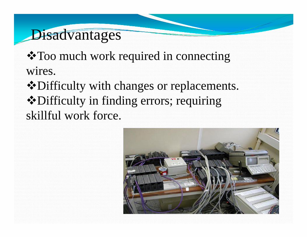
DisadvantagesToo much work required in connecting
wires.wires.Difficulty with changes or replacements.Difficulty in finding errors; requiringDifficulty in finding errors; requiring
skillful work force.
PLCs’ApplicationsPLCs Applications
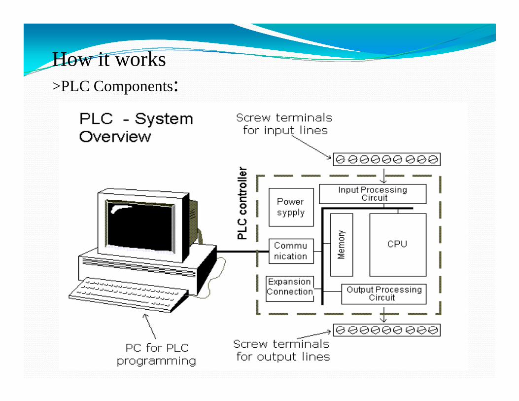
How it works>PLC Components:
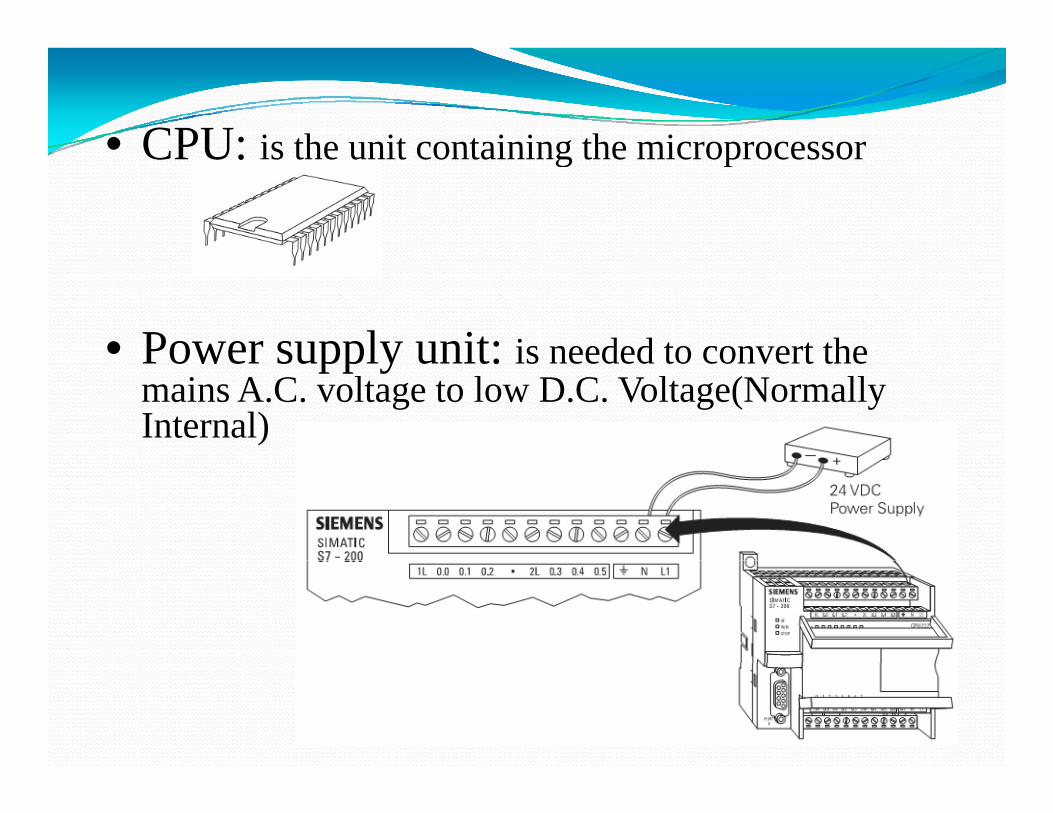
• CPU: is the unit containing the microprocessorCPU: is the unit containing the microprocessor
• Power supply unit: is needed to convert thePower supply unit: is needed to convert the mains A.C. voltage to low D.C. Voltage(Normally Internal)
• Input-output sections: are where the processor
i i f ti freceives information from external devices and communicates information
l d ito external devices.
The S7-200 PLCs are expandable. Expansion
• Expansion Modules:expandable. Expansion modules contain additional inputs and outputs. These are connected to the base unit using a ribbon connectorconnector.
• Memory unit: is where theMemory unit: is where the program is stored that is to be used for control actions.
• Programming device: is used to entered theis used to entered the required program into the memory of the processor.
PLC Operation: The PLC program is executed as PLC Operation: p gpart of a repetitive process referred to as a scan. A PLC scan starts with the CPU reading thestarts with the CPU reading the status of inputs. The application program is executed using the t t f th i t O thstatus of the inputs. Once the
program is completed, the CPU performs internal diagnostics and p gcommunication tasks. The scan cycle ends by updating the outputs then starts over Theoutputs, then starts over. The cycle time depends on the size of the program, the number of I/Os,
d th t f i tiand the amount of communication required.
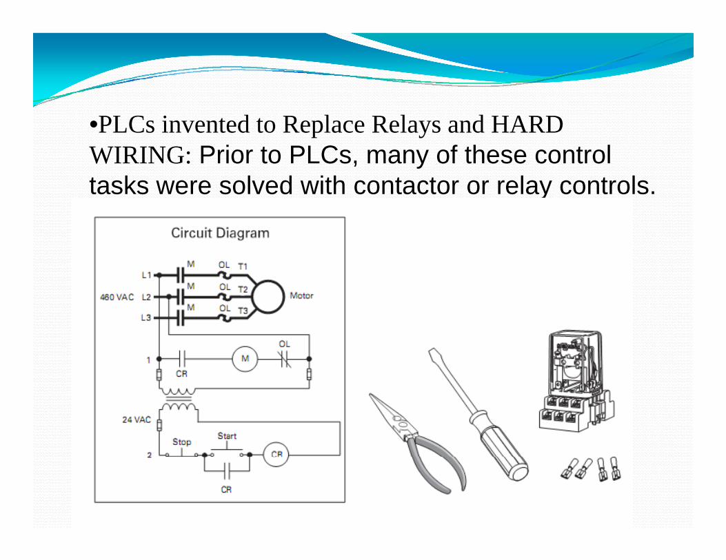
•PLCs invented to Replace Relays and HARD WIRING: Prior to PLCs, many of these control tasks were solved with contactor or relay controls.
Replacing Relay by PLCReplacing Relay by PLC
First step We have to translate all of the itemsFirst step- We have to translate all of the items we're using into symbols the plc understands
A contact symbol
A il b lA coil symbol
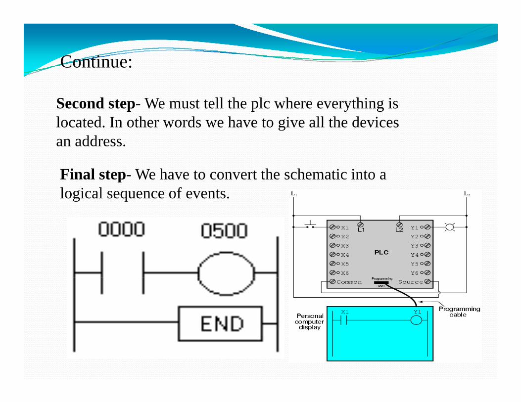
Continue:
Second step- We must tell the plc where everything is located In other words we have to give all the deviceslocated. In other words we have to give all the devices an address.
Final step- We have to convert the schematic into aFinal step- We have to convert the schematic into a logical sequence of events.
Ladder Diagram and Programming:Ladder Diagram and Programming:
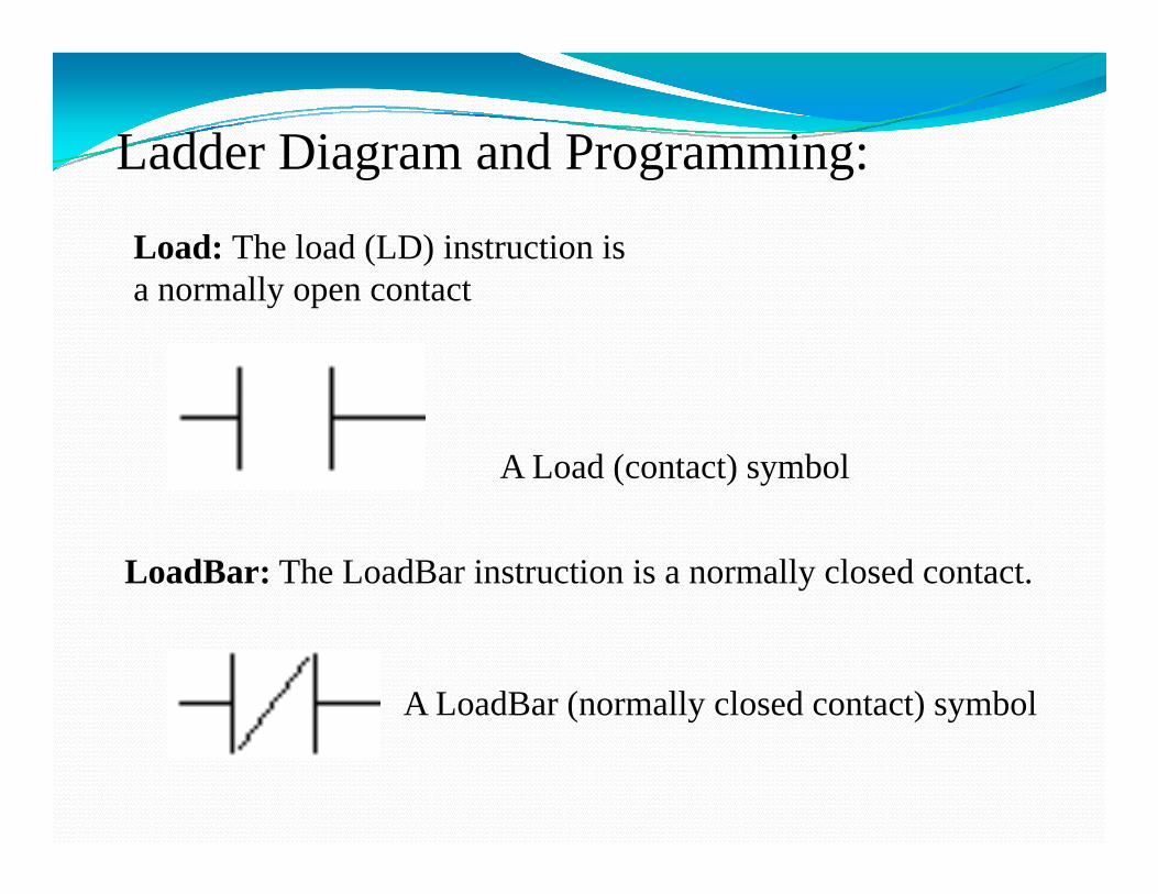
Load: The load (LD) instruction is lla normally open contact
A Load (contact) symbol
LoadBar: The LoadBar instruction is a normally closed contact.
A LoadBar (normally closed contact) symbol
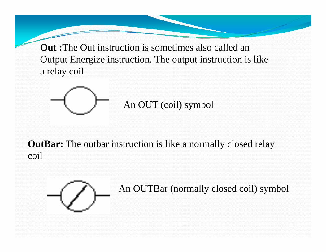
Out :The Out instruction is sometimes also called anOut :The Out instruction is sometimes also called an Output Energize instruction. The output instruction is like a relay coil
An OUT (coil) symbol
O tB Th tb i t ti i lik ll l d lOutBar: The outbar instruction is like a normally closed relay coil
An OUTBar (normally closed coil) symbol
Logic elementsLogic elements
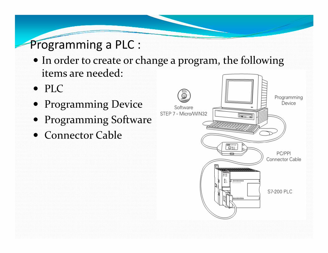
Programming a PLC :Programming a PLC :In order to create or change a program, the following items are needed:PLCProgramming DeviceProgramming SoftwareConnector Cable
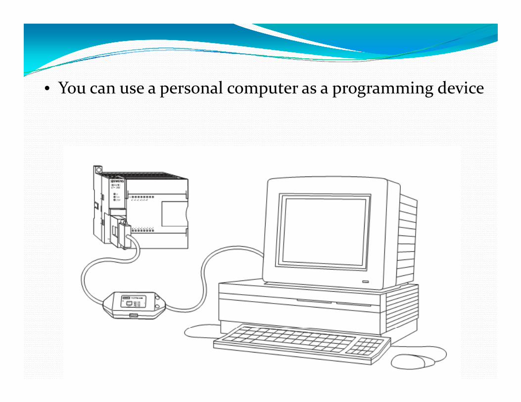
• You can use a personal computer as a programming device
Testing a programOnce a program has been written it needs to be tested and debugged One way this can be done is to simulate the field debugged. One way this can be done is to simulate the field inputs with an input simulator, The program is first downloaded from the PC to the CPU. The selector switch is placed in the RUN position. The simulator switches are operated and the resulting indication is observed on the output
Examples of Ladder pdiagram(Example One):
We can simulate this same circuit with a ladder diagram:with a ladder diagram:
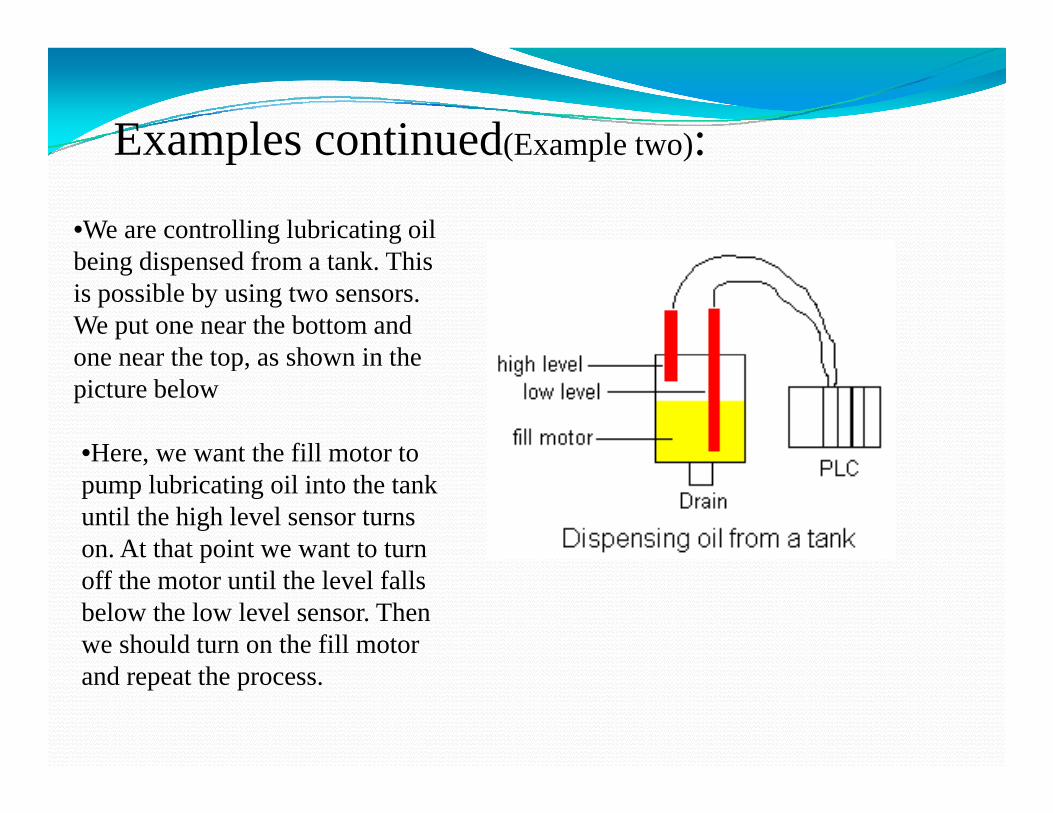
•We are controlling lubricating oil b i di d f k Thibeing dispensed from a tank. This is possible by using two sensors. We put one near the bottom and one near the top as shown in theone near the top, as shown in the picture below
•Here we want the fill motor toHere, we want the fill motor to pump lubricating oil into the tank until the high level sensor turns on. At that point we want to turn poff the motor until the level falls below the low level sensor. Then we should turn on the fill motor and repeat the process.
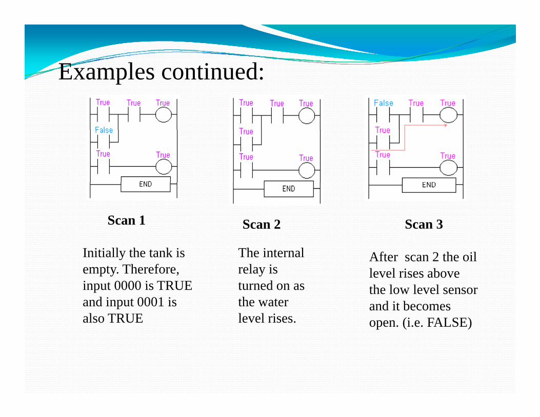
Initially the tank is empty. Therefore, input 0000 is TRUE
After scan 2 the oil level rises above th l l l
The internal relay is turned on asinput 0000 is TRUE
and input 0001 is also TRUE
the low level sensor and it becomes open. (i.e. FALSE)
turned on as the water level rises.
Examples continued:
Scan 6Scan 4
After scan 4 the oil level rises above the
Scan 5
Since there is no more true logic path output
Scan 6
After scan 6 the oil level falls belowlevel rises above the
high level sensor at it also becomes open (i.e. false)
true logic path, output 500 is no longer energized (true) and therefore the motor
level falls below the high level sensor and it will become true again. )
turns off.g
Examples continued:Examples continued:
Ladder diagram with Latching(Example three)
Regular output coils are of course an essential part of our programs but weRegular output coils are of course an essential part of our programs but we must remember that they are only TRUE when ALL INSTRUCTIONS before them on the rung are also TRUE.
Please think back about the lunch bell example. We would've had to keep pressing the button for as long as we p g gwanted the bell to sound. (A momentary switch) The latching instructions let us use momentary switches and program the plc so that when we push one the output turns on and when we push another the output turns off.
Example Continued
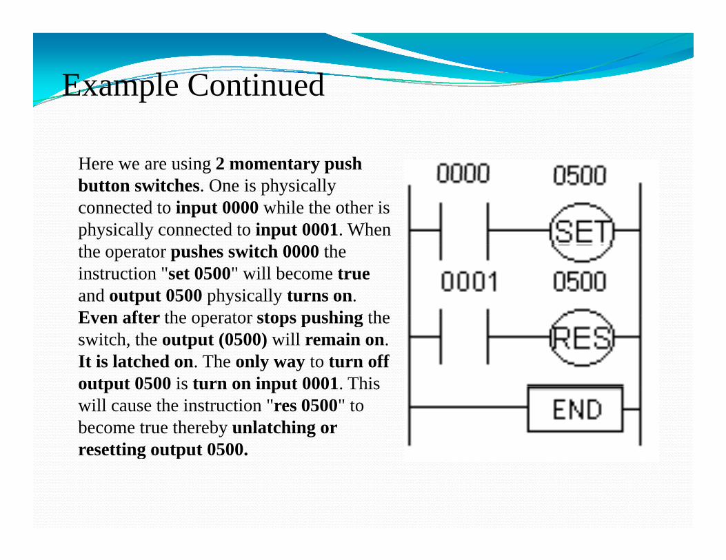
Here we are using 2 momentary push button switches. One is physically connected to input 0000 while the other is physically connected to input 0001. When h hthe operator pushes switch 0000 the
instruction "set 0500" will become trueand output 0500 physically turns on. Even after the operator stops pushing theEven after the operator stops pushing the switch, the output (0500) will remain on. It is latched on. The only way to turn off output 0500 is turn on input 0001 Thisoutput 0500 is turn on input 0001. This will cause the instruction "res 0500" to become true thereby unlatching or resetting output 0500.g p
Example Continued
Example of Ladder diagram with Counter(Example Four)
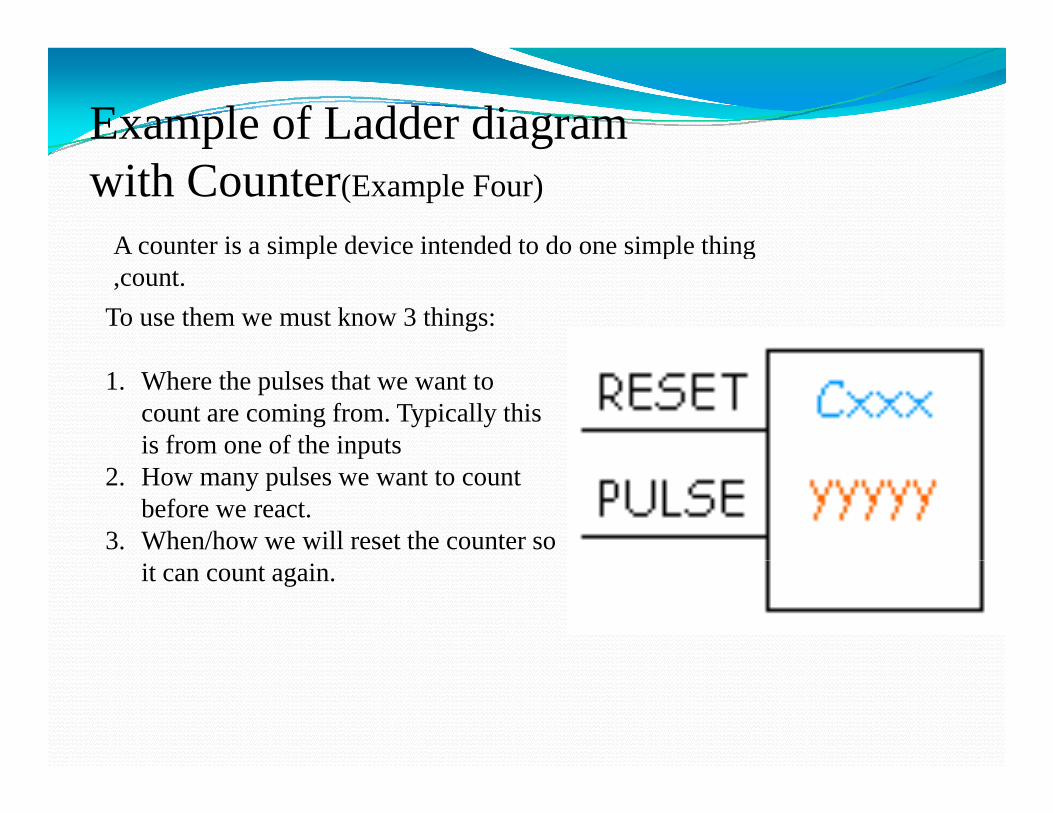
A counter is a simple device intended to do one simple thingA counter is a simple device intended to do one simple thing ,count.
To use them we must know 3 things:
1. Where the pulses that we want to count are coming from. Typically this is from one of the inputsp
2. How many pulses we want to count before we react.
3. When/how we will reset the counter so it can count again.
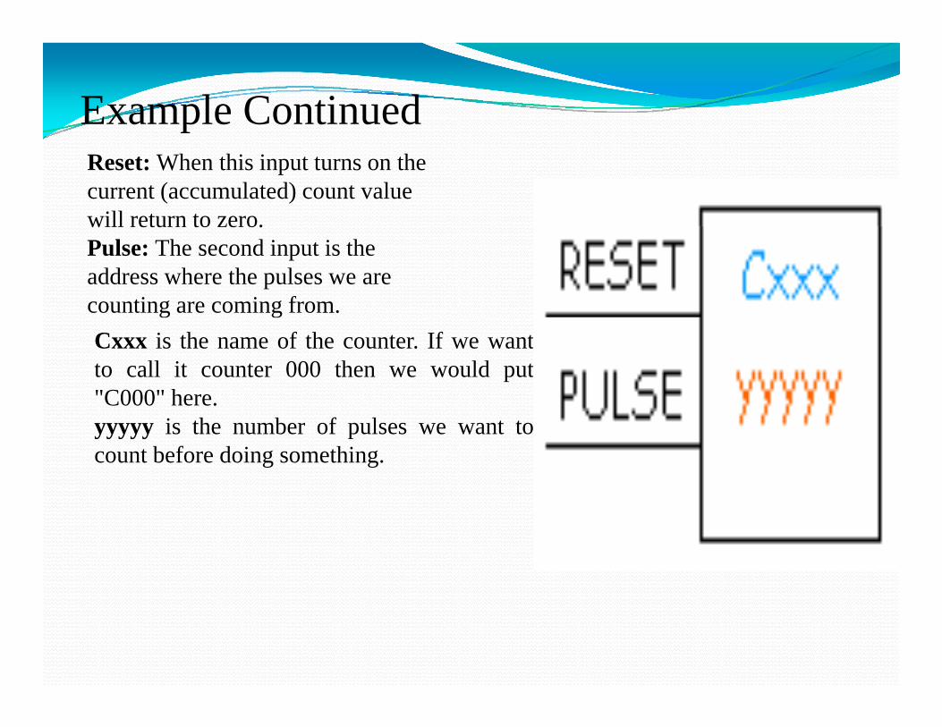
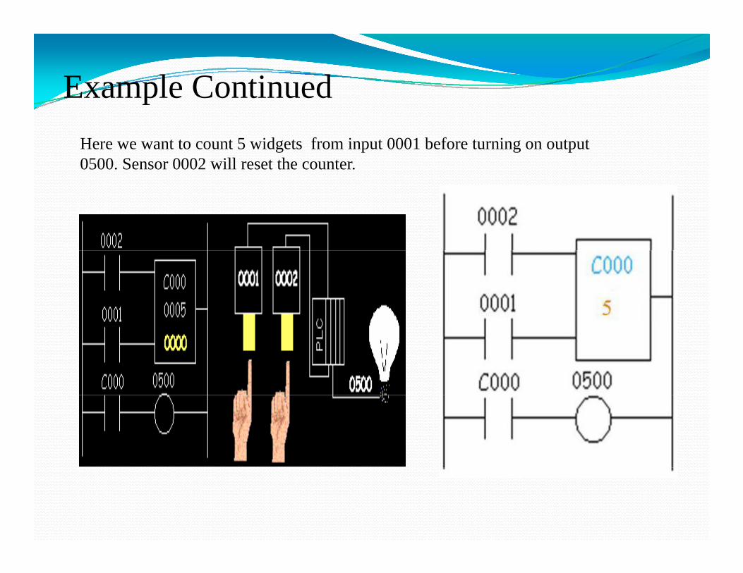
Example ContinuedReset: When this input turns on the current (accumulated) count value will return to zero.will return to zero.Pulse: The second input is the address where the pulses we are counting are coming from. Cxxx is the name of the counter. If we wantto call it counter 000 then we would put"C000" here.yyyyy is the number of pulses we want tocount before doing something.
Example ContinuedHere we want to count 5 widgets from input 0001 before turning on output 0500. Sensor 0002 will reset the counter.
Ladder diagram with Timer(Example five)
Timer: it is an instruction that waits a set amountTimer: it is an instruction that waits a set amount of time before doing something
There 3 types of timers: 1. On-Delay :when the input is on it waits y
second to turn on the output2. Off-Delay timer : when the input is on it
wits x seconds to turn off the output.3. Retentive or Accumulating timer : this
timer has two inputs. One starts timing and th th t th ti Th / ffthe other one resets the timer. The on/off delay timers above would be reset if the input sensor wasn't on/off for the complete timer duration This timer however holds or retainsduration. This timer however holds or retains the current elapsed time when the sensor turns off in mid-stream.
Example Continued
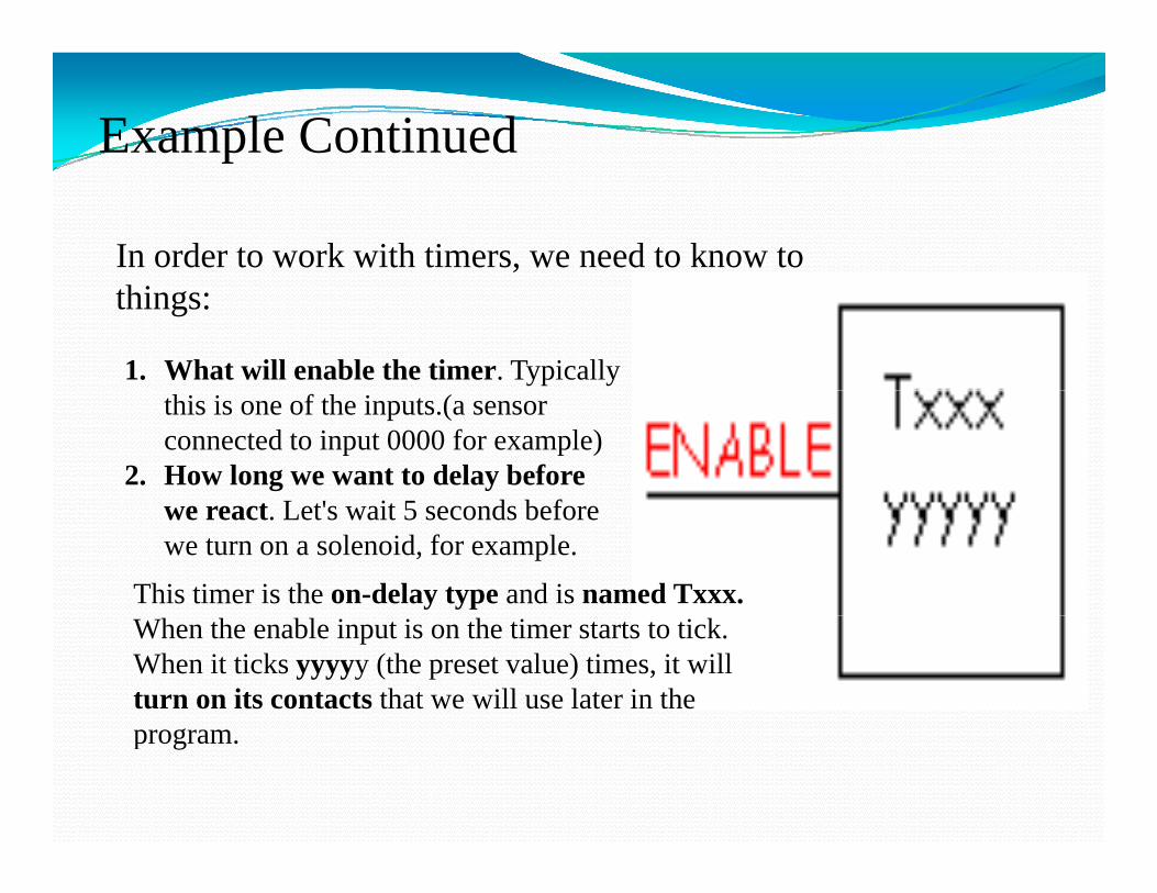
In order to work with timers, we need to know to things:
1. What will enable the timer. Typically this is one of the inputs.(a sensor connected to input 0000 for example)
2. How long we want to delay before t L t' it 5 d b fwe react. Let's wait 5 seconds before
we turn on a solenoid, for example.
This timer is the on-delay type and is named Txxx. When the enable input is on the timer starts to tick. When it ticks yyyyy (the preset value) times, it will turn on its contacts that we will use later in the program.
Example Continued
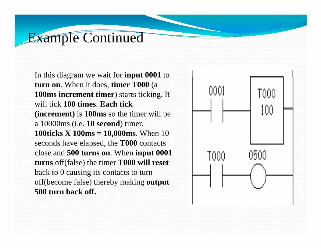
In this diagram we wait for input 0001 toIn this diagram we wait for input 0001 to turn on. When it does, timer T000 (a 100ms increment timer) starts ticking. It will tick 100 times. Each tick (increment) is 100ms so the timer will be a 10000ms (i.e. 10 second) timer. 100ticks X 100ms = 10,000ms. When 10 seconds have elapsed, the T000 contacts close and 500 turns on. When input 0001 turns off(false) the timer T000 will reset b k t 0 i it t t t tback to 0 causing its contacts to turn off(become false) thereby making output 500 turn back off.
Example Continued
Example For an other type of timer(Example six):
Accumulating timer : This timer is named Txxx. When the enable input is on the timer starts to tick. When it ticks yyyyy (the preset value) i i ill i h itimes, it will turn on its contacts that it
will be used later in the program.
In this type of timer if the enable input turnsIn this type of timer if the enable input turns off before the timer has completed, the current value will be retained. When the input turns back on, the timer will continuep ,from where it left off. The only way to force the timer back to its preset value to start again is to turn on the reset input.
Remember that the duration of a tick (increment) varies with the vendor and the time base used. (i.e. a tick might be 1ms or 1 second or...)
Example Continued
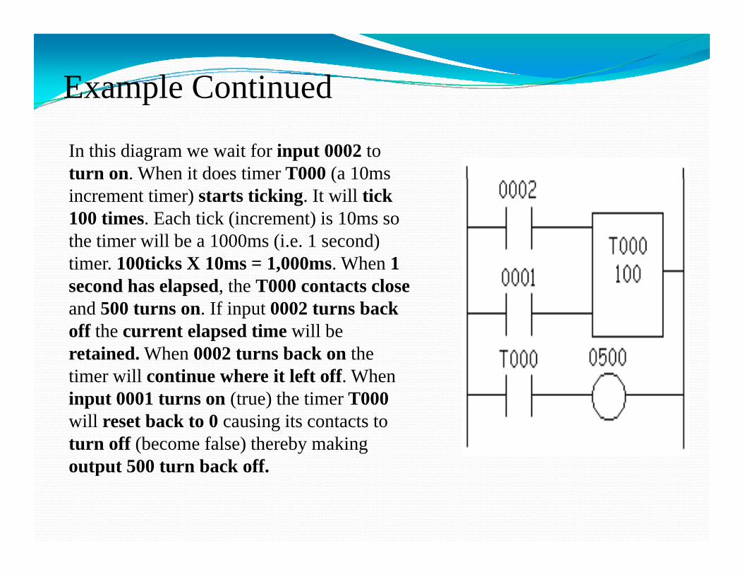
In this diagram we wait for input 0002 to turn on. When it does timer T000 (a 10msturn on. When it does timer T000 (a 10ms increment timer) starts ticking. It will tick 100 times. Each tick (increment) is 10ms so the timer will be a 1000ms (i.e. 1 second) timer. 100ticks X 10ms = 1,000ms. When 1 second has elapsed, the T000 contacts close and 500 turns on. If input 0002 turns back off the current elapsed time will be retained. When 0002 turns back on the timer will continue where it left off. When i t 0001 t (t ) th ti T000input 0001 turns on (true) the timer T000 will reset back to 0 causing its contacts to turn off (become false) thereby making output 500 turn back offoutput 500 turn back off.
Example Continued
Examples of Ladder diagram(Example Seven):SIEMENS PLCs
p g ( p )
• SIEMENS S7-200, CPU 222.
• 8 Inputs 6 Outputs• 8 Inputs, 6 Outputs.
• 256 Counters & Timers.
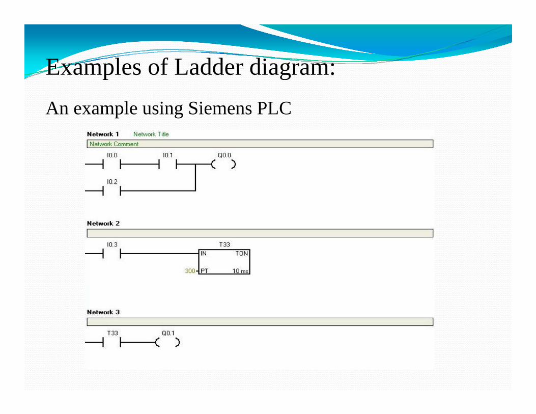
Examples of Ladder diagram:An example using Siemens PLC
p g
Examples Continuedp
This Exam gives a complete understanding of input, output, OR and AND commands in ladder diagram and Timer Here it isand AND commands in ladder diagram, and Timer. Here it is shown that if input I0.0 and I0.1 are on then output Q0.0 will turn on and this part explains the AND command. Output Q0.0 can also be activated if input I0.2 is on, which shows the OR command. In network two it is shown that when input I0.3 is activated a timer will count 3 seconds (300ms×10ms=3 s) and ( )then this timer will activate the output Q0.1 .
Examples Continued(Example Eight)p ( p g )
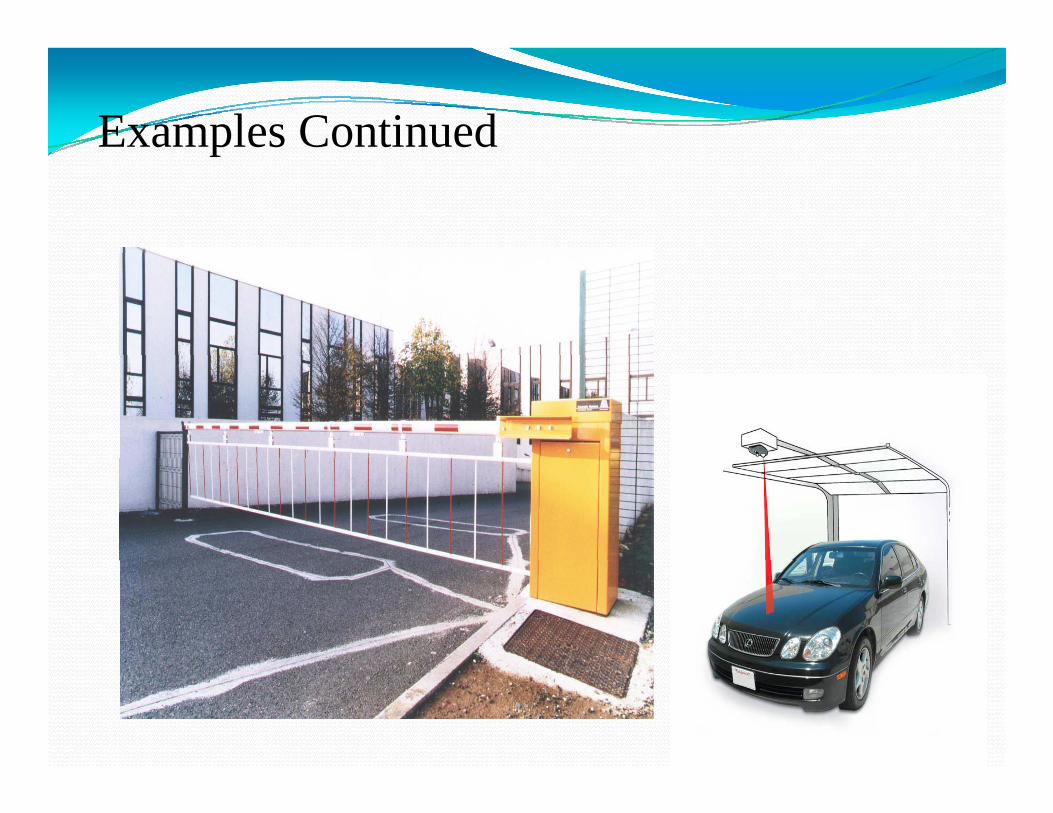
In this assignment you are asked to imagine a parking lot. These are one entranceand one exit in this parking garage. You are asked to draw the ladder diagram ofthis system by considering the requirements mentioned here. Both the entranceand exit gates are open with remote control and you can assume that there is ai f d t t th i l f th t t l d i thi iinfrared sensor to get the signal from the remote control and since this sensor isconnected to PLC, as it gets the signal it is processed in PLC and entrance or exitgate will open. There are two infrared sensors one is placed toward the entranceand the other one is placed toward the exit so they will not interfere Since youand the other one is placed toward the exit so they will not interfere. Since youneed the system to keep the gate open after someone presses the remote controlbutton, you may need a latching switch for both entrance and exit. In additionyou need the gates to be open only for 20 second and the timing increment ofy g p y gyour PLC is 10ms. Moreover since you do not want the gate to damage your carif it takes more than 20 seconds to pass the gates, there are 2 sensor placed atentrance and exit gate (one for entrance and one for exit) to keep the gate openwhen a car is passing through.
Examples Continuedp
Example Solution
I00
Example Solution
Q01SET
I00T33 I01
I01 Q01
R Q01
I00
Reset
T33
I02 Q01
T33
2000 10ms
Solution DescriptionpIn this example as I mentioned there should be a latching system to keep the gate open and close it after a car passes through. Here I00 is the infrared
h k h d f h l A i hsensor that takes the command from the remote control. As it get the command it opens the gate Q01 and at the same time it will activated the 20 second timer T33
I00 I00Q01 T33SET 2000 10ms
Solution Description ContinuedpAfter 20 second the timer activate the switch I01 which will reset the output Q01, in other words it will close the gate. But this example does not finish here. A sensor is required to keep the gate open if a car is still in the gate way. So an other infrared sensor I02 is used here to keep the gate open and it is connected to Q01.
I01 Q01Reset
T33 I02I01 Q01T33 I02I01 Q01
Example(Example Nine)
Automatic water sprinkler system of a garden
This example is based on Automatic wateri kl t f d It d li t tsprinkler system of a garden. It delivers water to
grass, flowers and trees. Watering of wholed d d h idit d t tgarden depends upon humidity and temperature
conditions which are adjustable.
Example PictureExample Picture
Example Continued
This example is one of the most complicated examples in this presentation Here the water sprinkler system (Q0 0) starts topresentation. Here the water sprinkler system (Q0.0) starts to work when either temperature sensor(I0.0) or humidity sensor (I0.1) send a signal to it. In this scenario grass will be water first ( t th Q0 1) f 4 d (it i d ll f(water the grass Q0.1) fro 4 second (it is assumed very small for simplicity) and then flowers will be water (water the flowers Q0.2) for 10 second and at last trees will be watered (water the trees Q0.3) for 18 seconds. Since it is required to avoid pressure drop in the water line ,each section is separated and here the order to water this garden is given: First grass second flowersorder to water this garden is given: First grass, second flowers and third trees.
Example ContinuedHere you can see that either temperature sensor I0.0 or humidity sensor I0.1 can turn on the sprinkler system (Q0.0). If the p y (Q )humidity or temperature falls below a specific point the system will start working.
Example Continued
Example Continued
In this Example it is needed to water the grass for 4 seconds. Since the increment is 10 ms it is written 400ms in the timerSince the increment is 10 ms, it is written 400ms in the timer. The input is assume to be the Q0.0 which was the switch for sprinkler system. Here it is assumed that if the sprinkler is on, the output Q0.1 will also become on and it will remain on for 4 seconds. If you take a look at the ladder diagram you will see that the input Q0.0 turn the timer on and it will count 4 seconds p Quntil it breaks the second line.
Example Continued
Since the input switch Q0.0 turn on all the timers in this ladder diagram at the same time it is required to add the time fordiagram at the same time it is required to add the time for watering of each section with the time elapsed in the previous sequence. For example although it is required to water the fl f l 10 d b t i th ti it i itt 1400flowers for only 10 second but in the timer it is written 1400ms with the increment 10 ms which will eventually be equal to 14 second. Now if you subtract 14 seconds from 4 second (the time required for the first section) you will get the required time which is 10 seconds. There is one more important parameter here In the ladder diagram it is written if the firstparameter here. In the ladder diagram it is written if the first section is done start the second section. You can see this in the second line of the ladder diagram. The output here is Q0.2
hi h i d f t i flwhich is assumed for watering flowers.
Example Continued
Example ContinuedThis part is like the second part. Watering the trees is started when previous section are finished. The time for this section is 18 second which is added to 14 seconds counted before and now it is written as 3200 ms with 10ms increment. You can see when both Q0.1 and Q0.2 are off the third part (Q0.3) iswhen both Q0.1 and Q0.2 are off the third part (Q0.3) is started.
Example(Example Ten)Example(Example Ten)
This example is based on a parking lot with a PLC which counts the number of cars that enter and exit and if thecounts the number of cars that enter and exit and if the parking lot is about to be full, PLC sends a signal to a electronic board to say that the parking is full. The system is also utilizing a infrared sensor to open the gates with remote control.(The capacity of this parking lot is assumed to be 5 cars.))
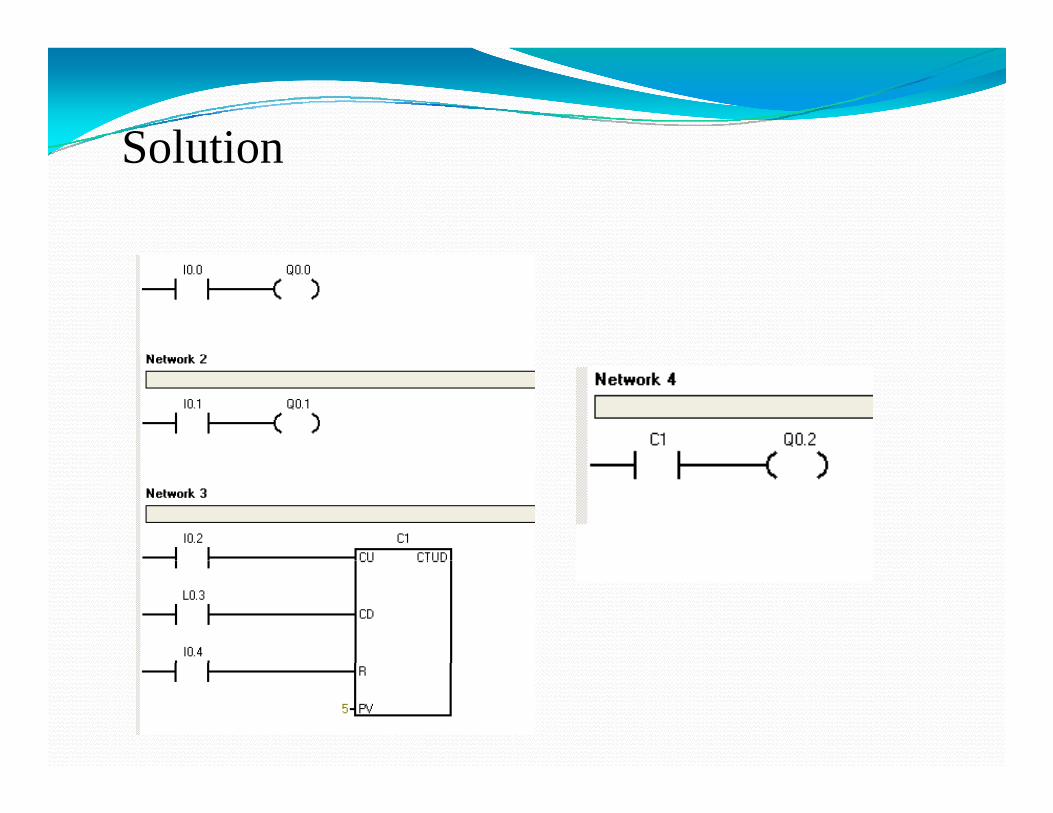
SolutionSolution
Example ContinuedExample Continued
In this example input I0.0 open the entrance gate and input I0 1 h i I0 0 d I0 1 b h i f dI0.1 opens the exit gate. I0.0 and I0.1 are both infrared sensors which will be activated by remote control. In addition sensor I0.2 count the number of cars entering the parking lot g p gand sensor I0.3 counts the cars leaving . The switch I0.4 is used to reset the system. If a total number of 5 cars enter this parking lot counter C1 send a signal to the electronic boardparking lot, counter C1 send a signal to the electronic board Q0.2 to show that the parking is full.
Programmable logic controlh " " l h h h hA PLC has many "input" terminals, through which it
interprets "high" and "low" logical states from sensors and switches.It also has many output terminals through which it It also has many output terminals, through which it outputs "high" and "low" signals to power lights, solenoids, contactors, small motors, and other devices lending themselves to on/off control. I ff k PLC h i In an effort to make PLCs easy to program, their programming language was designed to resemble ladder logic diagrams.Thus an industrial electrician or electrical engineer Thus, an industrial electrician or electrical engineer accustomed to reading ladder logic schematics would feel comfortable programming a PLC to perform the same control functions.
ContCont.Inside the PLC housing,
d b h i connected between each input terminal and the Common terminal, is an opto‐isolator device that provides an device that provides an electrically isolated "high" logic signal to the computer's circuitry when there is 120 VAC power
li d b t th ti applied between the respective input terminal and the Common terminal. An indicating LED on the front panel of the PLC gives p gvisual indication of an "energized" input as in figure.
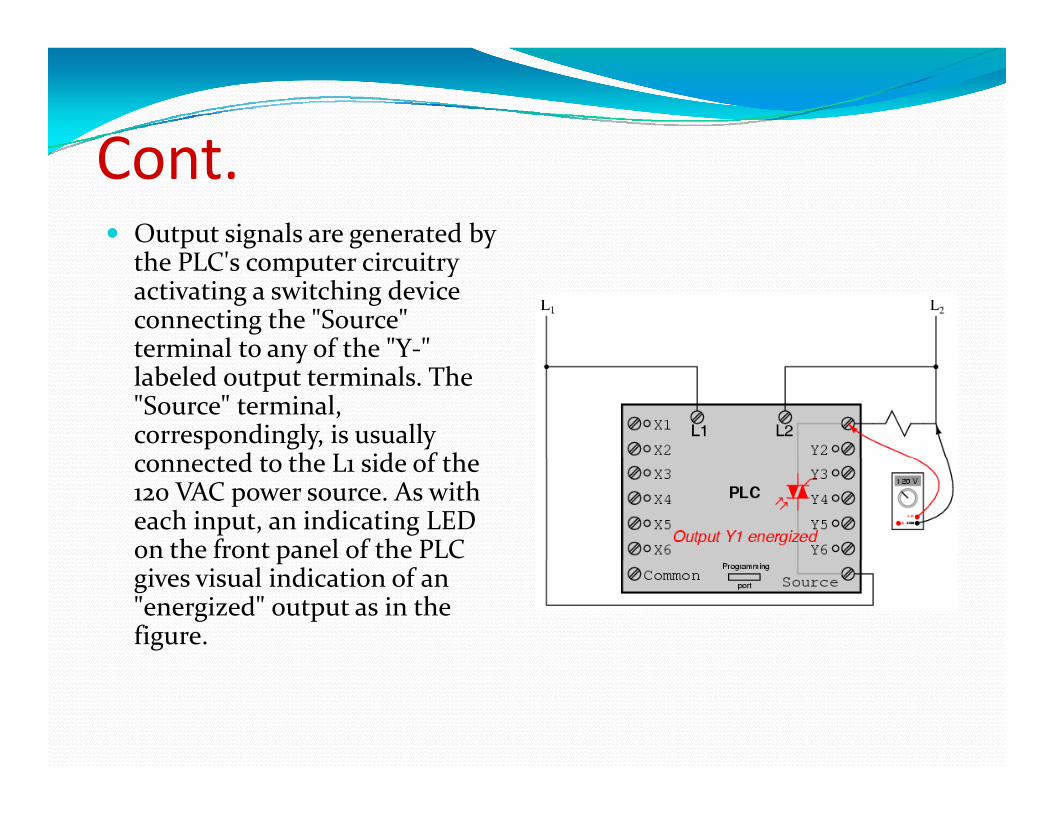
ContCont.Output signals are generated by h PLC' i i the PLC's computer circuitry activating a switching device connecting the "Source" terminal to any of the "Y‐" terminal to any of the Y labeled output terminals. The "Source" terminal, correspondingly, is usually
t d t th L id f th connected to the L1 side of the 120 VAC power source. As with each input, an indicating LED on the front panel of the PLC pgives visual indication of an "energized" output as in the figure.
cont.In this way, the PLC is able to interface with real‐world devices such as switches and solenoids. Th t l l i f th t l t i The actual logic of the control system is established inside the PLC by means of a computer program. This program dictates which output gets p g p g p genergized under which input conditions.The program is entered and viewed via a personal
d h PLC' i computer connected to the PLC's programming port.
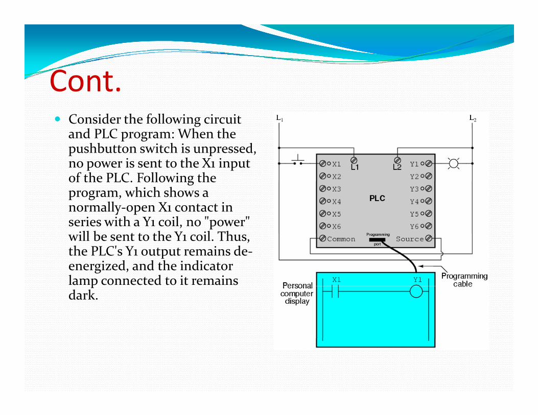
ContCont.Consider the following circuit
d PLC Wh h and PLC program: When the pushbutton switch is unpressed, no power is sent to the X1 input of the PLC. Following the of the PLC. Following the program, which shows a normally‐open X1 contact in series with a Y1 coil, no "power" ill b t t th Y il Th will be sent to the Y1 coil. Thus,
the PLC's Y1 output remains de‐energized, and the indicator lamp connected to it remains pdark.
ContCont.If the pushbutton switch is pressed ho e er po er ill be pressed, however, power will be sent to the PLC's X1 input. Any and all X1 contacts appearing in the program will assume the actuated (non normal) state as actuated (non‐normal) state, as though they were relay contacts actuated by the energizing of a relay coil named "X1". In this case energizing the X1 this case, energizing the X1 input will cause the normally‐open X1 contact will "close," sending "power" to the Y1 coil. When the Y1 coil of the program When the Y1 coil of the program "energizes," the real Y1 output will become energized, lighting up the lamp connected to it:
Cont.In the following illustration, we have the altered system shown in the state where the pushbutton is unactuated (not being pressed:
In this next illustration, the switch is shown actuated (pressed):
ContCont.One of the advantages of i l i l i l l i implementing logical control in software rather than in hardware is that input signals can be re‐used as many times in the used as many times in the program as is necessary.For example, take the following circuit and program, designed to energize the lamp if at least two of the threepushbutton switches are simultaneously actuated simultaneously actuated.
ContCont.To build an equivalent circuit using electromechanical relays three relays electromechanical relays, three relays with two normally‐open contacts each would have to be used, to provide two contacts per input switch.Using a PLC, however, we can program as many contacts as we wish for each "X" as many contacts as we wish for each X input without adding additional hardware, since each input and each output is nothing more than a single bit in the PLC's digital memory (either 0 or 1) and can be recalled as many times as 1), and can be recalled as many times as necessary.since each output in the PLC is nothing more than a bit in its memory as well, we can assign contacts in a PLC program " t t d" b t t (Y) t t T k "actuated" by an output (Y) status. Take for instance this next system, a motor start‐stop control circuit:
ContCont.If we were to press the "S " b i X "Start" button, input X1 would energize, thus "closing" the X1 contact in the program sending the program, sending "power" to the Y1 "coil," energizing the Y1 output and applying 120 volt AC a d app y g 0 o t Cpower to the real motor contactor coil. The parallel Y1 contact will also "close," h l hi h " i i " thus latching the "circuit" in an energized state:
contcont.To stop the motor, we To stop the motor, we must momentarily press the "Stop" pushbutton, which will energize the X2 input
d " " th and "open" the normally‐closed "contact " breaking contact, breaking continuity to the Y1 "coil:"
In this motor control circuit example, we have a problem: if the input wiring for X2 (the "Stop" g ( pswitch) were to fail open, there would be no way to stop the motor!pThe solution to this problem is a reversal of logic between the X2 logic between the X2 "contact" inside the PLC program and the actual "Stop" pushbutton switch:Stop pushbutton switch:
contcont.To demonstrate how one of h "i l" l these "internal" relays might be used, consider the following example circuit and program circuit and program, designed to emulate the function of a three‐input NAND gate. Since PLC gate. S ce Cprogram elements are typically designed by single letters, I will call the i l l l "C " internal control relay "C1" rather than "CR1" as would be customary in a relay control circuit: control circuit:
ContCont.In this circuit, the lamp In this circuit, the lamp will remain lit so long as any of the pushbuttons remain unactuated ( d) T k (unpressed). To make the lamp turn off, we will have to actuate will have to actuate (press) all three switches, like this: ,
Cont.This section on programmable logic controllers illustrates just a small sample of their capabilities.A t PLC f ti i f ti As computers, PLCs can perform timing functions drum sequencing, and other advanced functions with far greater accuracy and reliability than what g y yis possible using electromechanical logic devices.Most PLCs have the capacity for far more than six i d i inputs and six output