NFATEC – L11b – Design of composite structures for fire (25/05/2003) {LASTEDIT} CLE 20/5/03 {/LASTEDIT} {LECTURE} {LTITLE} EC4 Design of Composite Structures for Fire {/LTITLE} {AUTHOR} Bruno {/AUTHOR} {EMAIL} [email protected]{/EMAIL} {OVERVIEW} Traditional fire protection of steelwork is usually achieved by covering it with an insulating material during construction. However it may be possible under {ECLINK}EC4{/ECLINK} to use a combination of strategies to ensure fire resistance. EC4 calculation of fire resistance takes account of the loading level on the element. However the safety factors applied are lower than in those used in strength design. EC4 provides simple calculations for the load resistance in fire of common types of elements. In case of composite beams lateral-torsional buckling is neglected, and for columns the buckling fire resistance can be estimated according to code rules only for the case of braced frames. Fire resistance of composite beams comprising steel beam and concrete or composite slab may be calculated in terms of time, as a load-bearing resistance at a certain time, or as a critical element temperature appropriate to the load level and required time of exposure. Other members (composite slabs, composite beams comprising steel beams with partial concrete encasement, composite columns with partially encased steel sections and concrete-filled hollow sections) are examined in terms of the required fire resistance time.
Transcript
NFATEC – L11b – Design of composite structures for fire (25/05/2003)
Traditional fire protection of steelwork is usually achieved by covering it with an insulating material during construction. However it may be possible under {ECLINK}EC4{/ECLINK} to use a combination of strategies to ensure fire resistance. EC4 calculation of fire resistance takes account of the loading level on the element. However the safety factors applied are lower than in those used in strength design.
EC4 provides simple calculations for the load resistance in fire of common types of elements. In case of composite beams lateral-torsional buckling is neglected, and for columns the buckling fire resistance can be estimated according to code rules only for the case of braced frames. Fire resistance of composite beams comprising steel beam and concrete or composite slab may be calculated in terms of time, as a load-bearing resistance at a certain time, or as a critical element temperature appropriate to the load level and required time of exposure. Other members (composite slabs, composite beams comprising steel beams with partial concrete encasement, composite columns with partially encased steel sections and concrete-filled hollow sections) are examined in terms of the required fire resistance time.
EC4 provides tabular design data for some structural types which are not easily addressed by simplified calculation methods.
To assure the composite action during the fire exposure and the transmission of the applied forces and moments in the beam to column connections some constructional requirements must be fulfilled.
{/OVERVIEW}
{PREREQUISITES}
• Simple element design for strength and serviceability according to EC3 and EC4.
• Framing systems currently used in steel-framed construction, including composite systems.
• The effects of temperature on the properties of steel and concrete.
{/PREREQUISITES}
{OBJECTIVES}
On successful completion of this lecture you should:
• Understand that some types of composite members provide a considerable degree of inherent fire resistance which may either reduce or eliminate the need for additional passive protection materials.
• Understand that a range of strategies may be used in fire engineering design to provide the required fire resistance, including over-design, selection of framing systems, and use of sprinklers.
• Understand the principles of the simple design calculations of resistance in fire conditions of composite slabs, beams and columns, and the concept of critical temperature.
• Know how to calculate the sagging and hogging moment resistance of composite slabs.
• Know how to use the bending moment resistance method for calculation of the fire resistance of composite beams.
• Know how to calculate the capacity in fire of composite columns of different types, including the use of EC4 tabular data.
{/OBJECTIVES}
{SECTION}
{STITLE}
Introduction
{/STITLE}
{SUMMARY}
EC4 Part 1.2 deals with the passive, or inherent, fire safety of the composite structures and components (beams, columns and slabs) which are designed for ambient-temperature performance using EC4 Part 1.1.
Structural elements must carry their loads in fire conditions, and those which separate different compartments must also retain sufficient integrity and provide sufficient insulation to prevent fire spread.
Different methods are provided to establish these criteria.
{IMAGE}L11bImage1.gif{/IMAGE}
{PPT}
Lecture11bIntro.pps
{/PPT}
{DETAIL}
EC 4 Part 1.2 deals with the passive fire safety concept applied to composite steel and concrete structures.
The design methods presented in this document are valid only for structures or parts of structures within the scope of {ECLINK}EC4 Part 1.1 (Fig. 1){/ECLINK}.
{FIGURE}Typical examples of various types of composite steel and concrete sections{/FIGURE}
{/DETAIL}
{/SUMMARY}
{/SECTION}
{SECTION}
{STITLE}
Structural fire design
{/STITLE}
{SUMMARY}
EC4 Part 1.2 deals with the passive, or inherent, fire safety of the composite structures and components (beams, columns and slabs) which are designed for ambient-temperature performance using EC4 Part 1.1.
{PPT}
Lecture11bGeneral.pps
{/PPT}
{DETAIL}
It is necessary to recall that elements of structure must comply with three criteria in the event of fire:
• Integrity criterion ("E") – cracks or openings, which can cause fire penetration by hot gases or flames, must not occur, {ECLINK}EC4 Part 1.2{/ECLINK}
• Insulation criterion ("I") – the temperatures on the non-exposed surface of separating elements must not exceed ignition temperatures,
• Load-bearing criterion ("R") – structural members must maintain their load-bearing function during the whole required fire resistance time.
ENV 1994-1-2 covers principally the load-bearing criterion "R", although at a simpler level it also covers the integrity of compartments "E" and insulation "I". It allows three approaches to the assessment of structural behaviour in a fire design situation:
• Simple Calculation Models for specific types of structural members, {ECLINK}EC4 Part 1.2{/ECLINK}
• Established solutions, presented as Tabular Data for specific types of structural members,
• Advanced Calculation Models which simulate the behaviour of the global structure, of parts of the structure, or of isolated structural members.
Tabular data and simple calculation models can only be used for particular types of structural members under prescribed conditions. It is assumed that structural members are directly exposed to fire over their full length, so that the temperature distribution is the same over the whole length. Both methods give conservative results.
{/DETAIL}
{/SUMMARY}
{TEST}
{TTITLE}
Structural fire design criteria
{/TTITLE}
{QUESTION}
{QTITLE}
Structural fire design criteria for loadbearing walls
{/QTITLE}
{QTYPE}MC{/QTYPE}
{QTEXT}
Walls and floors (all with a load-bearing function) of a fire compartment should comply with these criteria:
{/QTEXT}
{ANSWER}E
{CHECKMARK}1{/CHECKMARK}
{CHECK}Yes – walls do need integrity{/CHECK}
{UNCHECKMARK}0{/UNCHECKMARK}
{UNCHECK}Can we allow flames to pass through walls and floors?{/UNCHECK}
{/ANSWER}
{ANSWER}I
{CHECKMARK}1{/CHECKMARK}
{CHECK}Yes – walls do need insulation{/CHECK}
{UNCHECKMARK}0{/UNCHECKMARK}
{UNCHECK}What happens to adjacent compartments if walls do not have sufficient insulation?{/UNCHECK}
{/ANSWER}
{ANSWER}R
{CHECKMARK}1{/CHECKMARK}
{CHECK}Yes – walls do need load-bearing resistance{/CHECK}
{UNCHECKMARK}0{/UNCHECKMARK}
{UNCHECK}Remember: these are load-bearing walls.{/UNCHECK}
{/ANSWER}
{FEEDBACK}
In the case of load-bearing walls and floors of fire compartments, cracks or openings which can cause fire penetration by hot gases or flames must not occur (integrity Criterion E). The temperatures on the non-exposed surfaces of compartment walls and floors must not exceed ignition temperatures (insulation Criterion I) and they must maintain their load-bearing function during the whole required fire resistance time (load-bearing Criterion R).
{/FEEDBACK}
{/QUESTION}
{QUESTION}
{QTITLE}
Structural fire design criteria for beams and columns
{/QTITLE}
{QTYPE}MC{/QTYPE}
{QTEXT}
Steel and composite load-bearing members (beams and columns) of fire compartments should comply with these criteria:
{/QTEXT}
{ANSWER}E
{CHECKMARK}0{/CHECKMARK}
{CHECK} Do beams and columns separate compartments? {/CHECK}
{UNCHECKMARK}1{/UNCHECKMARK}
{UNCHECK} No – beams and columns do not need to satisfy the integrity criterion {/UNCHECK}
{/ANSWER}
{ANSWER}I
{CHECKMARK}0{/CHECKMARK}
{CHECK}Do beams and columns keep compartments separate?{/CHECK}
{UNCHECKMARK}1{/UNCHECKMARK}
{UNCHECK} No – beams and columns do not need to satisfy the insulation criterion {/UNCHECK}
{/ANSWER}
{ANSWER}R
{CHECKMARK}1{/CHECKMARK}
{CHECK} Yes – beams and columns do need load-bearing resistance {/CHECK}
{UNCHECKMARK}0{/UNCHECKMARK}
{UNCHECK} Think: what is the function of beams and columns?{/UNCHECK}
{/ANSWER}
{FEEDBACK}
Load-bearing members such as beams and columns must maintain only their load-bearing function during the whole required fire resistance time (load-bearing criterion R).
{/FEEDBACK}
{/QUESTION}
{QUESTION}
{QTITLE}
Structural fire design criteria for separating walls
{/QTITLE}
{QTYPE}MC{/QTYPE}
{QTEXT}
Separating walls surrounding a fire compartment which have no load-bearing function should comply with these criteria:
{/QTEXT}
{ANSWER}E
{CHECKMARK}1{/CHECKMARK}
{CHECK}Yes – separating walls do need to satisfy the integrity criterion{/CHECK}
{UNCHECKMARK}0{/UNCHECKMARK}
{UNCHECK} Can we allow flames to pass through walls and floors?{/UNCHECK}
{/ANSWER}
{ANSWER}I
{CHECKMARK}1{/CHECKMARK}
{CHECK}Yes – separating walls do need to satisfy the insulation criterion{/CHECK}
{UNCHECKMARK}0{/UNCHECKMARK}
{UNCHECK} What happens to adjacent compartments if walls do not have sufficient insulation?{/UNCHECK}
{/ANSWER}
{ANSWER}R
{CHECKMARK}0{/CHECKMARK}
{CHECK} These are not load-bearing walls {/CHECK}
{UNCHECKMARK}1{/UNCHECKMARK}
{UNCHECK} No – separating walls do not need load-bearing resistance {/UNCHECK}
{/ANSWER}
{FEEDBACK}
In the case of separating walls without load-bearing function cracks or openings, which can cause fire penetration by hot gases or flames, must not occur (integrity Criterion E) and the temperatures on the non-exposed surfaces of compartment walls and floors must not exceed ignition temperatures (insulation Criterion I).
{/FEEDBACK}
{/QUESTION}
{/TEST}
{/SECTION}
{SECTION}
{STITLE}
Composite slabs
{/STITLE}
{SUMMARY}
It is sensible to consider fire engineering design of the main structural elements in composite construction in the order of their positions in the structural load-path.
The design of slabs affects the beams more directly than is the case in non-composite steel construction.
{ECLINK}EC4 Part 1.2{/ECLINK}
{/SUMMARY}
{SUMMARY}
{SUMTITLE}
Unprotected composite slabs
{/SUMTITLE}
Integrity Criterion "E" is automatically satisfied.
Insulation Criterion "I" depends on achieving a minimum effective thickness.
{IMAGE}Unprotected_composit.gif{/IMAGE}
{DETAIL}
Composite slabs are commonly used, particularly in unpropped construction when cast onto ribbed steel decking, a system which is advantageous in terms of speed and simplicity of construction. It is both a structural element and in general has also the function of separating individual fire compartments, and so it must comply with all three criteria. {ECLINK}EC4 Part 1.2{/ECLINK}
All the rules given in EC4 Part 1.2 for slabs are valid for both simply supported and continuous slabs. It is assumed that steel decking is not insulated but is heated directly, and that there is also no insulation between the structural concrete slab and surface screeds.
{/DETAIL}
{/SUMMARY}
{SUMMARY}
{SUMTITLE}
Unprotected composite slabs: Criteria "E" and "I"
{/SUMTITLE}
Integrity Criterion "E" is automatically satisfied.
Insulation Criterion "I" depends on achieving a minimum effective thickness.
{PPT}
Lecture11bUnprotectedSlabs.pps
{/PPT}
{DETAIL}
Criterion “E”
For composite slabs designed according to EC4 Part 1.1 it is assumed that the integrity Criterion is satisfied automatically.
Criterion “I”
The effectiveness of the insulation function of the composite slab depends on its effective thickness. {ECLINK}EC4 Part 1.2{/ECLINK}
{TIMAGE}Figure 4. Slab dimensions for estimation of effective thickness{/TIMAGE}
The effective slab thickness is calculated using the formula:
{EQN}heff_eqn1.gif{/EQN} for {EQN}h1h2_ratio1.gif{/EQN} and {EQN}h1_40.gif{/EQN} (1)
{EQN}heff_eqn2.gif{/EQN} for {EQN}h1h2_ratio2.gif{/EQN} and {EQN}h1_40.gif{/EQN} (1)
The effective thickness value obtained is then compared with the minimum values below, necessary to achieve the required fire resistance time.
Standard Fire Resistance
Minimum effective thickness
R30 60 – h3
R90 100 – h3
R180 150 – h3
{FIGURE}Table: Effective slab thicknesses related to slab fire{/FIGURE} resistance. {ECLINK}EC4 Part 1.2{/ECLINK}
For lightweight concrete values 10 % lower than these may be used.
In calculation of effective thickness it is permissible also to take into account screed, up to a maximum thickness of 20mm.
{/DETAIL}
{/SUMMARY}
{SUMMARY}
{SUMTITLE}
Unprotected composite slabs: Criterion "R"
{/SUMTITLE}
The load-bearing criterion "R" depends on the reduced strength of the principal structural components in the zones of hogging and sagging of the one-way spanning slabs between supporting beams. The steel sheeting is neglected since it separates from the concrete.
In sagging the tension reinforcement temperature is calculated from its mean distance from the exposed surfaces, and the concrete in compression is assumed to retain its full strength.
In hogging the concrete temperature profile for an effective slab depth is given, and the tension reinforcement is assumed to be at the same temperature as the concrete at its level.
{IMAGE}
Criterion_R.gif
{/IMAGE}
{PPT}
Lecture11bCriterionR.pps
{/PPT}
{DETAIL}
In a fire the mechanical properties of all structural materials degrade due to the high temperatures, which causes a decrease of both strength and flexural stiffness of the slab. When the design load-bearing resistance has decreased to the level of the design effect of the actions in the fire limit state then an ultimate condition has been reached. {ECLINK}EC4 Part 1.2{/ECLINK}
The steel decking is not taken into account in calculation of fire resistance. In fact, due to the high heat capacity of the concrete the concrete slab and the release of steam from the concrete surface, the temperature of the sheeting is much lower than the gas temperature at early stages of a fire. Considering this fact, a slab which has been designed for ambient temperatures according to the rules of {ECLINK}EC4 Part 1.1{/ECLINK} is assumed to have a fire resistance of 30 minutes without additional calculations.
In many cases, when the steel sheet is fixed to the supports (e.g. by stud connectors to the beams), or the parts of slabs near supports are cooler (in the case of a large plan), then axial deformations are prevented, so the slab is restrained in-plane. In such cases membrane forces can develop, and this may lead to an increase of the load-bearing resistance of the slab. This effect is the subject of current research at the present and is not yet included in the {ECLINK}EC4 Part 1.2{/ECLINK} rules.
Rules given in {ECLINK}EC4 Part 1.2{/ECLINK} for evaluation of load-bearing capacity are based on plastic global analysis. In the case of continuous slabs a redistribution of moments occurs as a result of changing stiffness, strength and thermal curvature due to high temperatures, so sufficient rotational capacity is required. This entails the provision of tensile reinforcement with sufficient deformation capacity and an adequate reinforcement ratio. This can be assured if the ambient-temperature slab design conforms to the rules of {ECLINK}EC2 Part 1.2{/ECLINK}.
Sagging moment resistance
In the calculation of sagging moment resistance not only the steel sheeting but also concrete in tension is neglected {ECLINK}EC4 Part 1.2 {/ECLINK}. As the insulation criterion must be fulfilled the temperature on the unexposed side will be low, and due to this fact the concrete in compression can be considered to have no reduction of strength. From this it is clear that the sagging moment resistance depends on the amount of tensile reinforcement (the reinforcement ratio) and its temperature. The temperature of the reinforcement depends on its distance from the heated surfaces. These are the perpendicular distances shown as {EQN}u1.gif{/EQN},
{EQN}u2.gif{/EQN} and {EQN}u3.gif{/EQN} in the figure below, and the reinforcement temperature is expressed as the function of its position {EQN}z.gif{/EQN}
{EQN}z_eqn.gif{/EQN} (3)
Limitations on the edge distances of the reinforcement are
{EQN}u1.gif{/EQN} and {EQN}u2.gif{/EQN}≥50mm,
{EQN}u3.gif{/EQN}≥35mm.
{ECLINK}EC4 Part 1.2{/ECLINK}
{IMAGE}
Geometrical_position.gif
{/IMAGE}
{TIMAGE}Figure 5. Geometrical position of the rebar; calculating {EQN}z.gif{/EQN} using perpendicular distances from heated surfaces.{/TIMAGE}
An example of temperature functions of reinforcement for some fire duration times is shown in the Table below.
Standard Fire Resistance
Temperature of the reinforcement [°C]
R60 {EQN}thetac_eq1.gif{/EQN} for {EQN}thetac_for1.gif{/EQN}
R120 {EQN}thetac_eq2.gif{/EQN} for {EQN}thetac_for2.gif{/EQN}
R240 {EQN}thetac_eq3.gif{/EQN} for {EQN}thetac_for3.gif{/EQN}
{FIGURE}Table: Reinforcement temperature functions for some Standard fire resistance times{/FIGURE}
Hogging moment resistance
The concrete in compression is on the exposed side of the slab, so a reduced strength must be considered. {ECLINK}EC4 Part 1.2 4.3.1.5{/ECLINK}This can be done in two ways; by integration over the depth of the ribs or by replacing the ribbed slab by an equivalent slab of uniform thickness heff according to 2.1.2, which is a more conservative method. Temperatures of uniform-thickness slabs are given in {ECLINK}EC4 Part 1.2{/ECLINK}.
The temperature of the tensile reinforcement can be taken as equal to the concrete temperature at the position of the bars. As this is usually placed at a minimum cover distance from the exposed surface the temperature influence is negligible in most cases.
The heating of a slab with effective thickness 100 mm at a standard fire duration of 60 minutes is shown.
{IMAGE}
Heating_of_a_100mm_f.gif
{/IMAGE}
{TIMAGE}Figure 6. Heating of a 100mm flat composite slab at 60 minutes{/TIMAGE}
{/DETAIL}
{/SUMMARY}
{SUMMARY}
{SUMTITLE}
Protected composite slabs
{/SUMTITLE}
If a slab is insulated with proprietary protection material then manufacturers’ data based on furnace tests must be used. If the steel sheet temperature is kept below 350 °C then the load-bearing criterion "R" is satisfied.
{IMAGE}
Protected_composite.gif
{/IMAGE}
{PPT}
Lecture11bProtectedSlabs.pps
{/PPT}
{DETAIL}
Composite slabs can be protected by the use of fire protection material or a suspended ceiling. {ECLINK}EC4 Part 1.2{/ECLINK}
{IMAGE}
Fire_protection_of_the_slab.gif
{/IMAGE}
{TIMAGE}Figure 7. Fire protection of the slab{/TIMAGE}
The relevant data for proprietary fire protection materials is given in manufacturers' literature, and for generic materials typical figures are provided in relevant codes. The fulfilment of the insulation criterion "I" is assured by the use of the EC4 rules for the load-bearing criterion "R", if the fire protection material is taken into account in the equivalent concrete thickness according to the appropriate codes.
It is assumed that the load-bearing criterion "R" is automatically fulfilled before the temperature of the steel sheeting reaches 350°C.
{/DETAIL}
{/SUMMARY}
{TEST}
{TTITLE}
Composite slabs
{/TTITLE}
{QUESTION}
{QTITLE}
Fire design criteria for separating floors
{/QTITLE}
{QTYPE}MC{/QTYPE}
{QTEXT}
Separating floors of a fire compartment must satisfy only the integrity (E) and insulation (I) criteria. True or False?
{/QTEXT}
{ANSWER}True
{CHECKMARK}0{/CHECKMARK}
{CHECK}No – floors also need to satisfy load-bearing criterion R{/CHECK}
{UNCHECKMARK}1{/UNCHECKMARK}
{UNCHECK}Correct – floors also need to satisfy load-bearing Criterion R{/UNCHECK}
{/ANSWER}
{ANSWER}False
{CHECKMARK}1{/CHECKMARK}
{CHECK}Correct – floors also need to satisfy load-bearing criterion R{/CHECK}
{UNCHECKMARK}0{/UNCHECKMARK}
{UNCHECK} No – floors also need to satisfy load-bearing Criterion R{/UNCHECK}
{/ANSWER}
{FEEDBACK}
Separating floors of fire compartments must always satisfy also the load-bearing criterion R, unlike non-load-bearing separating walls.
{/FEEDBACK}
{/QUESTION}
{QUESTION}
{QTITLE}
Structural fire design criteria for separating floors
{/QTITLE}
{QTYPE}MC{/QTYPE}
{QTEXT}
In the case of unprotected composite slabs the Insulation Criterion "I" is Part 1.2 satisfied automatically according to EC4. True or False?
{/QTEXT}
{ANSWER}True
{CHECKMARK}0{/CHECKMARK}
{CHECK}No – it depends on slab thickness{/CHECK}
{UNCHECKMARK}1{/UNCHECKMARK}
{UNCHECK}It depends on slab thickness{/UNCHECK}
{/ANSWER}
{ANSWER}False
{CHECKMARK}1{/CHECKMARK}
{CHECK}Correct – it depends on slab thickness{/CHECK}
{UNCHECKMARK}0{/UNCHECKMARK}
{UNCHECK}No – it depends on slab thickness{/UNCHECK}
{/ANSWER}
{FEEDBACK}
The insulation function of an unprotected composite slab depends on its thickness or effective thickness, and is not satisfied automatically.
{/FEEDBACK}
{/QUESTION}
{QUESTION}
{QTITLE}
Ultimate limit state for structural fire design
{/QTITLE}
{QTYPE}MC{/QTYPE}
{QTEXT}
An ultimate condition is reached when the design effect of the actions in the fire limit state has decreased to the level of the design load-bearing resistance. True or False?
{/QTEXT}
{ANSWER}True
{CHECKMARK}0{/CHECKMARK}
{CHECK}No - The actions (loads) stay constant {/CHECK}
{UNCHECKMARK}1{/UNCHECKMARK}
{UNCHECK} The actions (loads) stay constant {/UNCHECK}
{/ANSWER}
{ANSWER}False
{CHECKMARK}1{/CHECKMARK}
{CHECK}Yes - The actions (loads) stay constant{/CHECK}
{UNCHECKMARK}0{/UNCHECKMARK}
{UNCHECK} The actions (loads) stay constant{/UNCHECK}
{/ANSWER}
{FEEDBACK}
In the fire situation material properties of all material degrade due to the high temperatures, so the load-bearing resistance decreases and the effect of the actions remains constant.
{/FEEDBACK}
{/QUESTION}
{QUESTION}
{QTITLE}
Fire resistance of composite slabs
{/QTITLE}
{QTYPE}MC{/QTYPE}
{QTEXT}
Thanks to the effect of membrane forces a composite slab is assumed to have a fire resistance of 30 minutes without additional calculations. True or False?
{/QTEXT}
{ANSWER}True
{CHECKMARK}0{/CHECKMARK}
{CHECK}No – the assumed fire resistance is not due to membrane forces{/CHECK}
{UNCHECKMARK}1{/UNCHECKMARK}
{UNCHECK} The assumed fire resistance is not due to membrane forces{/UNCHECK}
{/ANSWER}
{ANSWER}False
{CHECKMARK}1{/CHECKMARK}
{CHECK}Correct – the assumed fire resistance is not due to membrane forces {/CHECK}
{UNCHECKMARK}0{/UNCHECKMARK}
{UNCHECK}The assumed fire resistance is not due to membrane forces{/UNCHECK}
{/ANSWER}
{FEEDBACK}
If a composite slab has been designed for ambient temperatures according to the rules of {ECLINK}EC4 Part 1.1{/ECLINK}. it is assumed to have a fire resistance of 30 minutes without additional calculations, but this is not due the effect of membrane forces. It is because, due to the high heat capacity of the concrete slab and the release of steam from the concrete surface, the temperature of the steel sheeting is kept much lower than the fire gas temperature at the early stages of a fire. Membrane forces develop only in some special cases, when axial deformations are prevented (e.g. when the steel sheet is fixed to the supports or the parts of slabs near supports are cooler).
{/FEEDBACK}
{/QUESTION}
{QUESTION}
{QTITLE}
Structural fire resistance of continuous slabs
{/QTITLE}
{QTYPE}MC{/QTYPE}
{QTEXT}
Rules given in {ECLINK}EC4 Part 1.2{/ECLINK}. for evaluation of load-bearing capacity in fire are based on plastic global analysis, so in the case of continuous slabs we automatically assume a redistribution of moments. True or False?
{/QTEXT}
{ANSWER}True
{CHECKMARK}0{/CHECKMARK}
{CHECK}No – sufficient rotation capacity is needed at supports{/CHECK}
{UNCHECKMARK}1{/UNCHECKMARK}
{UNCHECK}Sufficient rotation capacity is needed at supports{/UNCHECK}
{/ANSWER}
{ANSWER}False
{CHECKMARK}1{/CHECKMARK}
{CHECK}Correct – sufficient rotation capacity is needed at supports{/CHECK}
{UNCHECKMARK}0{/UNCHECKMARK}
{UNCHECK}Sufficient rotation capacity is needed at supports{/UNCHECK}
{/ANSWER}
{FEEDBACK}
For the redistribution of moments in the case of continuous slabs sufficient rotational capacity is required. This means that an adequate reinforcement ratio and sufficient deformation capacity of tensile reinforcement must be assured in hogging zones.
{/FEEDBACK}
{/QUESTION}
{QUESTION}
{QTITLE}
Relevant parameters for calculating slab resistance
{/QTITLE}
{QTYPE}MC{/QTYPE}
{QTEXT}
Select the parts of the cross-section which are taken into account when calculating sagging moment resistance according to {ECLINK}EC4 Part 1.2{/ECLINK}. (More than one correct answer is possible)
{IMAGE}
compo_slab_sag.gif
{/IMAGE}
{/QTEXT}
{ANSWER} a) Part 1 with reduced strength
{CHECKMARK}0{/CHECKMARK}
{CHECK}No – decking quickly reaches high temperatures{/CHECK}
{UNCHECKMARK}1{/UNCHECKMARK}
{UNCHECK}Decking quickly reaches high temperatures{/UNCHECK}
{/ANSWER}
{ANSWER} b) Part 2 with full strength
{CHECKMARK}0{/CHECKMARK}
{CHECK}No – tensile reinforcement strength reduces with temperature{/CHECK}
{UNCHECKMARK}1{/UNCHECKMARK}
{UNCHECK}Tensile reinforcement strength reduces with temperature{/UNCHECK}
{/ANSWER}
{ANSWER} c) Part 2 with reduced strength depending on effective depth
{CHECKMARK}0{/CHECKMARK}
{CHECK}No – reduction in reinforcement strength depends on its distance from the heated surfaces expressed as a function {EQN}z.gif{/EQN}.{/CHECK}
{UNCHECKMARK}1{/UNCHECKMARK}
{UNCHECK}Reduction in reinforcement strength depends on its distance from the heated surfaces expressed as a function {EQN}z.gif{/EQN}.{/UNCHECK}
{/ANSWER}
{ANSWER} d) Part 2 with reduced strength depending on its position
{CHECKMARK}1{/CHECKMARK}
{CHECK}Yes{/CHECK}
{UNCHECKMARK}0{/UNCHECKMARK}
{UNCHECK} {/UNCHECK}
{/ANSWER}
{ANSWER} e) Part 3 with reduced strength
{CHECKMARK}0{/CHECKMARK}
{CHECK}No – concrete in tension is ignored{/CHECK}
{UNCHECKMARK}1{/UNCHECKMARK}
{UNCHECK} Concrete in tension is ignored{/UNCHECK}
{/ANSWER}
{ANSWER} f) Part 4 with reduced strength
{CHECKMARK}0{/CHECKMARK}
{CHECK}No – concrete in compression is assumed to remain cool and its strength is unaffected.{/CHECK}
{UNCHECKMARK}1{/UNCHECKMARK}
{UNCHECK}Concrete in compression is assumed to remain cool and its strength is unaffected.{/UNCHECK}
{/ANSWER}
{ANSWER} g) Part 4 with full strength
{CHECKMARK}1{/CHECKMARK}
{CHECK}Yes – concrete in compression is assumed to remain cool and its strength is unaffected.{/CHECK}
{UNCHECKMARK}0{/UNCHECKMARK}
{UNCHECK} Concrete in compression is assumed to remain cool and its strength is unaffected.{/UNCHECK}
{/ANSWER}
{FEEDBACK}
Part 1 is the steel sheeting, whose temperature becomes very high after a reasonably long time, and therefore its strength becomes very low, and so it is neglected.
Part 2 is tensile reinforcement, whose temperature depends on its distance from the heated surfaces. These are the distances {EQN}u1.gif{/EQN}, {EQN}u2.gif{/EQN} and {EQN}u3.gif{/EQN} and the reinforcement temperature is expressed as a function {EQN}z.gif{/EQN} of its position: {EQN}z_eqn.gif{/EQN}.
Part 3 is concrete in tension, so it is neglected.
Part 4 is concrete in compression. As the insulation criterion must be fulfilled the temperature on the unexposed side will be low, and due to this fact the concrete in compression can be considered to have no reduction of strength.
{/FEEDBACK}
{/QUESTION}
{QUESTION}
{QTITLE}
Relevant parameters for calculating slab resistance in hogging
{/QTITLE}
{QTYPE}MC{/QTYPE}
{QTEXT}
Select the parts of the cross-section which are taken into account when calculating hogging moment resistance according to EC4 Part 1.2.
{IMAGE}
compo_slab_hog.gif
{/IMAGE}
{/QTEXT}
{ANSWER} a) Part 1 with reduced strength
{CHECKMARK}0{/CHECKMARK}
{CHECK}No – decking quickly reaches high temperatures{/CHECK}
{UNCHECKMARK}1{/UNCHECKMARK}
{UNCHECK}Decking quickly reaches high temperatures{/UNCHECK}
{/ANSWER}
{ANSWER} b) Part 2 with full strength
{CHECKMARK}0{/CHECKMARK}
{CHECK}No – reinforcement in the compression zone is not normally considered in slab design{/CHECK}
{UNCHECKMARK}1{/UNCHECKMARK}
{UNCHECK}Reinforcement in the compression zone is not normally considered in slab design{/UNCHECK}
{/ANSWER}
{ANSWER} c) Part 2 with reduced strength depending on its position: {EQN}z_qu_eqn.gif{/EQN}
{CHECKMARK}0{/CHECKMARK}
{CHECK}No – reinforcement in the compression zone is not normally considered in slab design{/CHECK}
{UNCHECKMARK}1{/UNCHECKMARK}
{UNCHECK}Reinforcement in the compression zone is not normally considered in slab design{/UNCHECK}
{/ANSWER}
{ANSWER} d) Part 2 with reduced strength depending on its position: {EQN}z_eqn.gif{/EQN}
{CHECKMARK}0{/CHECKMARK}
{CHECK}No – reinforcement in the compression zone is not normally considered in slab design{/CHECK}
{UNCHECKMARK}1{/UNCHECKMARK}
{UNCHECK}Reinforcement in the compression zone is not normally considered in slab design{/UNCHECK}
{/ANSWER}
{ANSWER} e) Part 3 with reduced strength
{CHECKMARK}1{/CHECKMARK}
{CHECK}Yes – tensile reinforcement strength reduces with temperature{/CHECK}
{UNCHECKMARK}0{/UNCHECKMARK}
{UNCHECK}Tensile reinforcement strength reduces with temperature{/UNCHECK}
{/ANSWER}
{ANSWER} f) Part 3 with full strength
{CHECKMARK}0{/CHECKMARK}
{CHECK}No – tensile reinforcement strength reduces with temperature.{/CHECK}
{UNCHECKMARK}1{/UNCHECKMARK}
{UNCHECK}Tensile reinforcement strength reduces with temperature.{/UNCHECK}
{/ANSWER}
{ANSWER} g) Part 4 with full strength
{CHECKMARK}0{/CHECKMARK}
{CHECK}No – concrete in tension is ignored{/CHECK}
{UNCHECKMARK}1{/UNCHECKMARK}
{UNCHECK}Concrete in tension is ignored{/UNCHECK}
{/ANSWER}
{ANSWER} h) Part 5 with reduced strength depending on its position from unexposed surface
{CHECKMARK}1{/CHECKMARK}
{CHECK}Yes{/CHECK}
{UNCHECKMARK}0{/UNCHECKMARK}
{UNCHECK}Yes{/UNCHECK}
{/ANSWER}
{ANSWER} i) Part 5 with full strength
{CHECKMARK}1{/CHECKMARK}
{CHECK}Yes{/CHECK}
{UNCHECKMARK}0{/UNCHECKMARK}
{UNCHECK}{/UNCHECK}
{/ANSWER}
{FEEDBACK}
Part 1 is the steel sheeting, becomes very high after a reasonably long time, and therefore its strength becomes very low, and so it is neglected.
Part 2 is reinforcement in the compression zone.
Part 3 is concrete in compression. The concrete is on the exposed side of the slab, so a reduced strength must be considered.
Part 4 is concrete in tension, so it is neglected.
Part 5 is tensile reinforcement. Its temperature can be taken as equal to the concrete temperature at the position of the bars. As this reinforcement is usually placed at a minimum cover distance from the unexposed surface the temperature influence is negligible in most cases, so both answers h and i are correct.
{/FEEDBACK}
{/QUESTION}
{/TEST}
{/SECTION}
{SECTION}
{STITLE}
Composite beams including steel sections with no concrete encasement
{/STITLE}
{SUMMARY}
The analysis of a composite beam including a "downstand" steel beam with no concrete encasement is divided into two steps:
thermal analysis for estimation of the temperature distribution in the cross-section,
mechanical analysis for calculation of the load-bearing resistance of the member under fire conditions.
{PPT}
Lecture11bCritcalTemp.pps
{/PPT}
{IMAGE}
Composite_beam_downstand.gif
{/IMAGE}
{DETAIL}
The analysis of a composite beam including a "downstand" steel beam with no concrete encasement is divided into two steps:
thermal analysis for estimation of the temperature distribution in the cross-section,
mechanical analysis for calculation of the load-bearing resistance of the member under fire conditions.
Thermal analysis
In {ECLINK}EC4 Part 1.2{/ECLINK} the same rules apply to calculation of the temperatures of unprotected and protected steel beams as are given in EC3 Part 1.2, which are described in the module "Background to structural fire engineering": Introduction to Structural Fire Engineering of this package{ECLINK}EC4 Part 1.2{/ECLINK}. There may be considerable differences in the temperatures of the lower and upper flanges, so it is very important that these should be calculated properly in order to obtain an accurate value of the bending moment resistance of a composite section.
Mechanical analysis
In {ECLINK}EC4 Part 1.2{/ECLINK} two methods are given for calculation of sagging bending moment resistance of beams without concrete encasement.
The Critical Temperature Method
The Critical Temperature Method {ECLINK}EC4 Part 1.2{/ECLINK} is a simplified method, which can be used for the case of simply supported composite beams
composed of hot-rolled downstand steel sections of up to 500mm depth and concrete slabs with a thickness of not less than 120mm. For such configurations it is assumed that the temperature over the depth of the steel section is uniform.
The advantage of this method is that it is not necessary to calculate the bending moment resistance in fire directly. The critical temperature is a function of the load level for the fire limit state, {EQN}etafit.gif{/EQN}:
{EQN}etafit_eqn.gif{/EQN} (4)
where {EQN}efidt.gif{/EQN} is the design effect of the actions in the fire situation, {EQN}rd.gif{/EQN} is the design load-bearing resistance for normal temperature design, {EQN}ed.gif{/EQN} is the design effect of actions for normal temperature design and
{EQN}etafi_eqn.gif{/EQN} (5)
In the fire situation the ultimate limit state is reached when the load-bearing resistance {EQN}rfidt.gif{/EQN} decreases to the level of the design effect of the actions in fire {EQN}efidt.gif{/EQN} so that the load level can be written as
{EQN}etafit_eqn2.gif{/EQN} (6)
It has been shown experimentally that the compressive strength of concrete has not a significant influence on the bending moment resistance of composite beams in fire. The reason for this is that the resultant tension in the steel section is rather small due to its high temperature. The neutral axis position is therefore high in the concrete slab, and only a small part of the slab is in compression. Considering this fact, it is clear that the bending moment resistance in the fire situation is influenced mainly by the steel strength, so
{EQN}etafit_eqn3.gif{/EQN} (7)
The critical temperature of the steel part is determined from the formula
{EQN}etafit09_eqn.gif{/EQN} (8)
and the value of the critical temperature obtained is then compared with the temperature of the steel section after the required fire duration, calculated from the formulas for unprotected or protected sections, as given in Section 2.1.3.1. The term {EQN}etafit09.gif{/EQN} is almost completely equivalent to the "Utilisation Factor" which is used in the same way in {ECLINK}EC3 Part 1.2{/ECLINK} for non-composite steel construction.
{/DETAIL}
{/SUMMARY}
{SUMMARY}
{SUMTITLE}
Bending moment resistance method
{/SUMTITLE}
{IMAGE}
Bending_moment_resistance_method.gif
{/IMAGE}
{PPT}
Lecture11bMR.pps
{/PPT}
{DETAIL}
If the steel section is deeper than 500 mm or the slab thickness is less than 120 mm, the Bending Moment Resistance Method must be used.
The bending moment resistance is calculated using simple plastic theory, so the steel section must be Class 1 or 2. The concrete slab must have sufficient rotational capacity, which is assured by the fulfilment of EC2 Part 1.2 requirements.
At the required fire resistance time the neutral axis position is obtained as usual from equilibrium of the tensile force {EQN}t.gif{/EQN} in the lower part and the compressive force {EQN}f.gif{/EQN} in the upper part.
{IMAGE}
Temperature_stress.gif
{/IMAGE}
{TIMAGE}
Figure 8. Temperature and stress distribution for composite beam comprising concrete slab and downstand steel section
{/TIMAGE}
Temperature and stress distribution for composite beam comprising concrete slab and downstand steel section
Assuming that the neutral axis position is in the concrete slab, the tensile force in the steel section is given by:
{EQN}t_eqn.gif{/EQN} (9)
and the depth of concrete in compression results from the equation:
{EQN}f_eqn.gif{/EQN} (10)
The sagging moment resistance is then obtained from
{EQN}mfird_eqn.gif{/EQN} (11)
This process can also be used for a composite slab with profiled steel sheeting, if the slab depth is replaced by {EQN}heff.gif{/EQN} (Section 2.1.1.2). It is also important to check whether the temperature of the compressed concrete zone {EQN}hu.gif{/EQN} is less than 250°C (using the process shown in Section 2.1.1.3), otherwise the following more complicated formula for the estimation of {EQN}hu.gif{/EQN} should be used:
{EQN}f_eq_t_eqn.gif{/EQN} (12)
which can be solved by iteration, assuming a stepped temperature profile using the average temperatures at 10mm steps:
{EQN}t_eq_f_eqn.gif{/EQN} (13)
{/DETAIL}
{/SUMMARY}
{SUMMARY}
{SUMTITLE}
Shear resistance
{/SUMTITLE}
It is important that the concrete slab remains composite with the steel beam section during heating. It must be verified that the shear connectors can transmit the horizontal shear stress from the steel to the concrete at high temperature. This is controlled by the lower of the shear strength of the shear studs and the capacity of the concrete in which they are embedded.
{PPT}
Lecture11bShear.pps
{/PPT}
{DETAIL}
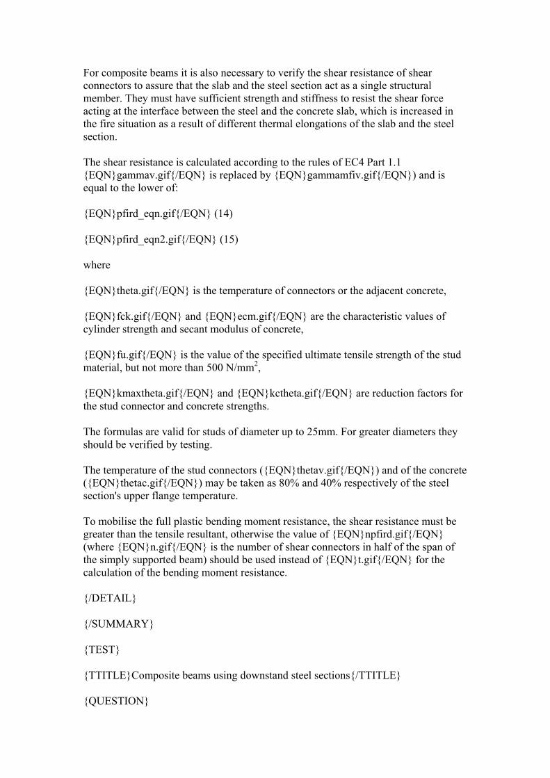
For composite beams it is also necessary to verify the shear resistance of shear connectors to assure that the slab and the steel section act as a single structural member. They must have sufficient strength and stiffness to resist the shear force acting at the interface between the steel and the concrete slab, which is increased in the fire situation as a result of different thermal elongations of the slab and the steel section.
The shear resistance is calculated according to the rules of EC4 Part 1.1 {EQN}gammav.gif{/EQN} is replaced by {EQN}gammamfiv.gif{/EQN}) and is equal to the lower of:
{EQN}pfird_eqn.gif{/EQN} (14)
{EQN}pfird_eqn2.gif{/EQN} (15)
where
{EQN}theta.gif{/EQN} is the temperature of connectors or the adjacent concrete,
{EQN}fck.gif{/EQN} and {EQN}ecm.gif{/EQN} are the characteristic values of cylinder strength and secant modulus of concrete,
{EQN}fu.gif{/EQN} is the value of the specified ultimate tensile strength of the stud material, but not more than 500 N/mm2,
{EQN}kmaxtheta.gif{/EQN} and {EQN}kctheta.gif{/EQN} are reduction factors for the stud connector and concrete strengths.
The formulas are valid for studs of diameter up to 25mm. For greater diameters they should be verified by testing.
The temperature of the stud connectors ({EQN}thetav.gif{/EQN}) and of the concrete ({EQN}thetac.gif{/EQN}) may be taken as 80% and 40% respectively of the steel section's upper flange temperature.
To mobilise the full plastic bending moment resistance, the shear resistance must be greater than the tensile resultant, otherwise the value of {EQN}npfird.gif{/EQN} (where {EQN}n.gif{/EQN} is the number of shear connectors in half of the span of the simply supported beam) should be used instead of {EQN}t.gif{/EQN} for the calculation of the bending moment resistance.
{/DETAIL}
{/SUMMARY}
{TEST}
{TTITLE}Composite beams using downstand steel sections{/TTITLE}
{QUESTION}
{QTITLE}Applicability of the Critical Temperature Method
{/QTITLE}
{QTYPE}MC{/QTYPE}
{QTEXT}
In following question select the correct answers (more than one answer may be correct).
The Critical Temperature Method can be used in these cases:
{/QTEXT}
{ANSWER} a) for all hot-rolled downstand steel sections
{CHECKMARK}0{/CHECKMARK}
{CHECK}No{/CHECK}
{UNCHECKMARK}1{/UNCHECKMARK}
{UNCHECK}No{/UNCHECK}
{/ANSWER}
{ANSWER} b) for all welded downstand steel sections
{CHECKMARK}0{/CHECKMARK}
{CHECK}No{/CHECK}
{UNCHECKMARK}1{/UNCHECKMARK}
{UNCHECK}No{/UNCHECK}
{/ANSWER}
{ANSWER} c) for hot-rolled downstand steel sections up to 500 mm depth
{CHECKMARK}1{/CHECKMARK}
{CHECK}Yes{/CHECK}
{UNCHECKMARK}0{/UNCHECKMARK}
{UNCHECK}Yes{/UNCHECK}
{/ANSWER}
{ANSWER} d) for welded downstand steel sections up to 500 mm depth
{CHECKMARK}0{/CHECKMARK}
{CHECK}No{/CHECK}
{UNCHECKMARK}1{/UNCHECKMARK}
{UNCHECK}No{/UNCHECK}
{/ANSWER}
{ANSWER} e) for all steel sections
{CHECKMARK}1{/CHECKMARK}
{CHECK}Yes{/CHECK}
{UNCHECKMARK}0{/UNCHECKMARK}
{UNCHECK}Yes{/UNCHECK}
{/ANSWER}
{ANSWER} f) for all concrete and composite slabs
{CHECKMARK}0{/CHECKMARK}
{CHECK}No{/CHECK}
{UNCHECKMARK}1{/UNCHECKMARK}
{UNCHECK}No{/UNCHECK}
{/ANSWER}
{ANSWER} g) for all concrete and composite slabs with {EQN}hc.gif{/EQN} or {EQN}heff.gif{/EQN} not less than 120 mm
{CHECKMARK}1{/CHECKMARK}
{CHECK}Yes{/CHECK}
{UNCHECKMARK}0{/UNCHECKMARK}
{UNCHECK}Yes{/UNCHECK}
{/ANSWER}
{ANSWER} h) for all concrete and composite slabs with {EQN}hc.gif{/EQN} or {EQN}heff.gif{/EQN} not greater than 120 mm
{CHECKMARK}0{/CHECKMARK}
{CHECK}No{/CHECK}
{UNCHECKMARK}1{/UNCHECKMARK}
{UNCHECK}No{/UNCHECK}
{/ANSWER}
{ANSWER} i) for concrete and composite slabs with uniform thickness (without ribs) not greater than 120 mm
{CHECKMARK}0{/CHECKMARK}
{CHECK}No{/CHECK}
{UNCHECKMARK}1{/UNCHECKMARK}
{UNCHECK}No{/UNCHECK}
{/ANSWER}
{ANSWER} j) only for simple supported beams
{CHECKMARK}1{/CHECKMARK}
{CHECK}Yes{/CHECK}
{UNCHECKMARK}0{/UNCHECKMARK}
{UNCHECK}Yes{/UNCHECK}
{/ANSWER}
{ANSWER} k) only for continuous beams
{CHECKMARK}0{/CHECKMARK}
{CHECK}No{/CHECK}
{UNCHECKMARK}1{/UNCHECKMARK}
{UNCHECK}No{/UNCHECK}
{/ANSWER}
{ANSWER} l) for all statically determinate systems
{CHECKMARK}0{/CHECKMARK}
{CHECK}No{/CHECK}
{UNCHECKMARK}1{/UNCHECKMARK}
{UNCHECK}No{/UNCHECK}
{/ANSWER}
{FEEDBACK}
This simplified method can be used for the case of simply supported composite beams composed of concrete slabs with a thickness of not less than 120mm and hot-rolled downstand steel sections of up to 500mm depth, when it can be assumed that the temperature over the depth of the steel section is uniform.
{/FEEDBACK}
{/QUESTION}
{QUESTION}
{QTITLE}Parameters in the Critical Temperature Method
{/QTITLE}
{QTYPE}MC{/QTYPE}
{QTEXT}
In following question select the correct answer (more than one answer may be correct).
The critical temperature of a steel member is a function of:
{/QTEXT}
{ANSWER} a) the required fire resistance 30, 60, ... min
{CHECKMARK}0{/CHECKMARK}
{CHECK}No{/CHECK}
{UNCHECKMARK}1{/UNCHECKMARK}
{UNCHECK}No{/UNCHECK}
{/ANSWER}
{ANSWER} b) the load level for the fire limit state
{CHECKMARK}1{/CHECKMARK}
{CHECK}Yes{/CHECK}
{UNCHECKMARK}0{/UNCHECKMARK}
{UNCHECK}Yes{/UNCHECK}
{/ANSWER}
{ANSWER} c) the section coefficient {EQN}secfactor_unprot.gif{/EQN}
{CHECKMARK}0{/CHECKMARK}
{CHECK}No{/CHECK}
{UNCHECKMARK}1{/UNCHECKMARK}
{UNCHECK}No{/UNCHECK}
{/ANSWER}
{ANSWER} d) the time-temperature curve
{CHECKMARK}0{/CHECKMARK}
{CHECK}No{/CHECK}
{UNCHECKMARK}1{/UNCHECKMARK}
{UNCHECK}No{/UNCHECK}
{/ANSWER}
{ANSWER} e) the boundary conditions
{CHECKMARK}0{/CHECKMARK}
{CHECK}No{/CHECK}
{UNCHECKMARK}1{/UNCHECKMARK}
{UNCHECK}No{/UNCHECK}
{/ANSWER}
{FEEDBACK}
The critical temperature is the temperature at which the load-bearing resistance in the fire situation decreases to the level of the design effect of the actions in fire, and collapse of the member occurs. This depends only on the load level for the fire situation - the higher the load level, the lower the critical temperature.
{/FEEDBACK}
{/QUESTION}
{QUESTION}
{QTITLE}Load level
{/QTITLE}
{QTYPE}MC{/QTYPE}
{QTEXT}
The load level for the fire limit state
{EQN}etafit_eqn.gif{/EQN}
can in the case of composite beams with downstand steel sections be expressed also as {EQN}etafit_eqn4.gif{/EQN}. True or False?
{/QTEXT}
{ANSWER}True
{CHECKMARK}1{/CHECKMARK}
{CHECK}Yes{/CHECK}
{UNCHECKMARK}0{/UNCHECKMARK}
{UNCHECK}Yes{/UNCHECK}
{/ANSWER}
{ANSWER}False
{CHECKMARK}0{/CHECKMARK}
{CHECK}No{/CHECK}
{UNCHECKMARK}1{/UNCHECKMARK}
{UNCHECK}No{/UNCHECK}
{/ANSWER}
{FEEDBACK}
In the fire situation the resultant tension in the steel section is rather small due to high temperatures, so the neutral axis position is high in the concrete slab and only a small part of the slab is in compression. Due to these facts the compressive strength of concrete has no significant influence on the bending moment resistance, which is influenced mainly by the steel strength.
{/FEEDBACK}
{/QUESTION}
{QUESTION}
{QTITLE}The Moment Resistance Method
{/QTITLE}
{QTYPE}MC{/QTYPE}
{QTEXT}
In following question select the correct answers (more than one answer may be correct)
The bending moment resistance method can be used in these cases:
{/QTEXT}
{ANSWER} a) for all hot-rolled downstand steel sections only
{CHECKMARK}0{/CHECKMARK}
{CHECK}No{/CHECK}
{UNCHECKMARK}1{/UNCHECKMARK}
{UNCHECK}No{/UNCHECK}
{/ANSWER}
{ANSWER} b) for all welded downstand steel sections only
{CHECKMARK}0{/CHECKMARK}
{CHECK}No{/CHECK}
{UNCHECKMARK}1{/UNCHECKMARK}
{UNCHECK}No{/UNCHECK}
{/ANSWER}
{ANSWER} c) for hot-rolled downstand steel sections with depth greater than 500 mm
{CHECKMARK}0{/CHECKMARK}
{CHECK}No{/CHECK}
{UNCHECKMARK}1{/UNCHECKMARK}
{UNCHECK}No{/UNCHECK}
{/ANSWER}
{ANSWER} d) for welded downstand steel sections with depth greater than 500 mm
{CHECKMARK}0{/CHECKMARK}
{CHECK}No{/CHECK}
{UNCHECKMARK}1{/UNCHECKMARK}
{UNCHECK}No{/UNCHECK}
{/ANSWER}
{ANSWER} e) for all steel sections
{CHECKMARK}1{/CHECKMARK}
{CHECK}Yes{/CHECK}
{UNCHECKMARK}0{/UNCHECKMARK}
{UNCHECK}Yes{/UNCHECK}
{/ANSWER}
{ANSWER} f) for all concrete and composite slabs
{CHECKMARK}1{/CHECKMARK}
{CHECK}Yes{/CHECK}
{UNCHECKMARK}0{/UNCHECKMARK}
{UNCHECK}Yes{/UNCHECK}
{/ANSWER}
{ANSWER} g) for all concrete and composite slabs with {EQN}hc.gif{/EQN} or {EQN}heff.gif{/EQN} not less than 120 mm
{CHECKMARK}0{/CHECKMARK}
{CHECK}No{/CHECK}
{UNCHECKMARK}1{/UNCHECKMARK}
{UNCHECK}No{/UNCHECK}
{/ANSWER}
{ANSWER} h) for all concrete and composite slabs with {EQN}hc.gif{/EQN} or {EQN}heff.gif{/EQN} not greater than 120 mm
{CHECKMARK}0{/CHECKMARK}
{CHECK}No{/CHECK}
{UNCHECKMARK}1{/UNCHECKMARK}
{UNCHECK}No{/UNCHECK}
{/ANSWER}
{ANSWER} i) for concrete and composite slabs with uniform thickness (without ribs) not less than 120 mm
{CHECKMARK}0{/CHECKMARK}
{CHECK}No{/CHECK}
{UNCHECKMARK}1{/UNCHECKMARK}
{UNCHECK}No{/UNCHECK}
{/ANSWER}
{FEEDBACK}
The Bending Moment Resistance Method can be used for all steel sections and concrete slabs (in the case of a composite slab with profiled steel sheeting the slab depth is replaced by {EQN}heff.gif{/EQN}) as an alternative to Critical Temperature Method or in the cases when the Simplified Method cannot be used.
{/FEEDBACK}
{/QUESTION}
{QUESTION}
{QTITLE}Concrete strength
{/QTITLE}
{QTYPE}MC{/QTYPE}
{QTEXT}
In the fire situation the neutral axis position is high in the concrete (due to the high temperature of the steel section), so the compressed concrete zone is not affected by temperature and in the calculations is assumed to have full strength. True or False?
{/QTEXT}
{ANSWER}True
{CHECKMARK}0{/CHECKMARK}
{CHECK}No{/CHECK}
{UNCHECKMARK}1{/UNCHECKMARK}
{UNCHECK}No{/UNCHECK}
{/ANSWER}
{ANSWER}False
{CHECKMARK}1{/CHECKMARK}
{CHECK}Yes{/CHECK}
{UNCHECKMARK}0{/UNCHECKMARK}
{UNCHECK}Yes{/UNCHECK}
{/ANSWER}
{FEEDBACK}
The compressed concrete zone is assumed in the calculations to have full strength only if its temperature is less than 250°C. Otherwise the more complicated calculations taking into account the decrease of the strength with temperature must be
used. The compressed part of the concrete slab can be divided into layers each up to 10mm depth.
{/FEEDBACK}
{/QUESTION}
{QUESTION}
{QTITLE}Shear connection
{/QTITLE}
{QTYPE}MC{/QTYPE}
{QTEXT}
If the shear connectors are designed according to {ECLINK}EC4 Part 1.1{/ECLINK} it is not necessary to verify their shear resistance in fire situation, because they are protected by concrete and their temperature remains low. True or False?
{/QTEXT}
{ANSWER}True
{CHECKMARK}0{/CHECKMARK}
{CHECK}No{/CHECK}
{UNCHECKMARK}1{/UNCHECKMARK}
{UNCHECK}No{/UNCHECK}
{/ANSWER}
{ANSWER}False
{CHECKMARK}1{/CHECKMARK}
{CHECK}Yes{/CHECK}
{UNCHECKMARK}0{/UNCHECKMARK}
{UNCHECK}Yes{/UNCHECK}
{/ANSWER}
{FEEDBACK}
The temperature of the stud connectors ({EQN}thetav.gif{/EQN}) and of the surrounding concrete ({EQN}thetac.gif{/EQN}) may be taken as 80% and 40% respectively of the steel section's upper flange temperature, and therefore the shear resistance of the shear connector is influenced by temperature and must be verified in the fire situation.
{/FEEDBACK}
{/QUESTION}
{QUESTION}
{QTITLE}Shear resistance
{/QTITLE}
{QTYPE}MC{/QTYPE}
{QTEXT}
Even when the plastic method is used it is not necessary that the shear resistance must be greater than the tensile resultant in the steel part. True or False?
{/QTEXT}
{ANSWER}True
{CHECKMARK}1{/CHECKMARK}
{CHECK}Yes{/CHECK}
{UNCHECKMARK}0{/UNCHECKMARK}
{UNCHECK}Yes{/UNCHECK}
{/ANSWER}
{ANSWER}False
{CHECKMARK}0{/CHECKMARK}
{CHECK}No{/CHECK}
{UNCHECKMARK}1{/UNCHECKMARK}
{UNCHECK}No{/UNCHECK}
{/ANSWER}
{FEEDBACK}
It is true, in the case when the shear resistance is smaller than the tensile resultant in the steel part. The value of this shear resistance should be used instead of the tensile resultant for the calculation of the bending moment resistance.
{/FEEDBACK}
{/QUESTION}
{/TEST}
{/SECTION}
{SECTION}
{STITLE}
Composite beams including partially encased steel beams
{/STITLE}
{SUMMARY}
{SUMTITLE}
Composite beams comprising steel beams with partial concrete encasement
{/SUMTITLE}
A bending moment capacity method is given for composite beams with concrete fill between the flanges of the downstand steel I-section. Since the temperature distribution varies both horizontally and vertically in a fashion which is too complex for a design calculation, a mixture of techniques is used to calculate the reduced strength contributions of different parts of the composite cross-section.
{IMAGE}
reduced_section_partial_encase.gif
{/IMAGE}
{DETAIL}
This type of composite beam consists of a concrete slab (either flat or ribbed), a steel section and concrete placed between the flanges of the steel section. The rules given in {ECLINK}EC4 Part 1.2{/ECLINK} are valid for either simply supported or continuous beams including cantilevers. This contrasts with beams without concrete encasement to the steel section, which can only be considered as simply supported because of the possibility of local buckling at the connections.
For calculation purposes plastic theory is used and three-sided exposure is assumed. To ensure the validity of this assumption in the case of ribbed slabs with trapezoidal steel sheeting at least 90% of the upper flange must be covered.
The validity of the calculation procedures given in the Code is restricted by required minimum slab thickness and steel profile dimensions, both of which depend on the required fire safety class of the building. Examples of these dimensional restrictions are shown in the table below:
Minimum profile height h and width {EQN}bc.gif{/EQN} [mm] 120 170
Minimum area {EQN}h_dot_bc.gif{/EQN} [mm2] 17500 35000
Additional restrictions on the calculation are:
{EQN}ew_ineq.gif{/EQN}
{EQN}ef_ineq.gif{/EQN}({EQN}ew.gif{/EQN}, {EQN}bc.gif{/EQN}, {EQN}ef.gif{/EQN} and {EQN}h.gif{/EQN} are as defined below)
{IMAGE}
L11Image30.gif
{/IMAGE}
{TIMAGE}
Reduced section for calculation of sagging moment resistance
{/TIMAGE}
Thermal analysis
The heating of the cross-section is more complicated for partially encased beams than for simple downstand steel beams (Section 2.1.3). The lower flange of the steel beam is heated directly, while other parts are protected by the concrete placed between the flanges. This concrete encasement, as well as the reinforcement placed between the flanges, also contributes to the resistance. Due to these facts it is not possible to estimate the temperatures of the individual parts of the section by simple calculation and to compare them with a general critical temperature. The Code gives rules for
calculation of bending moment resistance for different fire resistance classes. For the purpose of calculation of the bending moment resistance, individual parts of the cross-section (lower steel flange and web, rebars between flanges), over which the temperature distribution is uniform or linearly varying, are assumed to have their full section but reduced strength. Horizontal areas heated non-uniformly are assumed to have full strength, but the parts affected by heat are excluded from the calculation (concrete infill, the lower parts {EQN}hcfi.gif{/EQN} of the concrete slab, the ends {EQN}bfi.gif{/EQN} of the upper steel flange).
{PPT}
Lecture11bPartEncase.pps
{/PPT}
{/DETAIL}
{/SUMMARY}
{SUMMARY}
{SUMTITLE}
Continuity
{/SUMTITLE}
In fire conditions beams which are considered as simply supported in ambient-temperature design may act as continuous. This is because of the lever arm between slab reinforcement, provided this is continuous across a column, and the steel-to-steel connection. Conditions are given for the compression to be transferred effectively through the steel-to-steel connection.
For simply supported beams the sagging moment resistance is compared with the maximum sagging moment of the beam , but for continuous beams the sagging moment resistance is compared with the maximum sagging moment in fire and the hogging moment resistance is compared with the maximum support moment in fire.
{IMAGE}
L11Image31.gif
{/IMAGE}
{TIMAGE}Figure 9. Conditions for maximum sagging and hogging moments{/TIMAGE}
In some cases beams which behave in normal temperature design as a simply supported may be considered as continuous in the fire case. This may occur when the concrete slab is reinforced adequately at its supports to guarantee its continuity, and provided that there can be effective transmission of the compression force through the steel connection.
{IMAGE}
L11Image32.gif
{/IMAGE}
{TIMAGE}Figure 10. Detail of beam-to-column connection to ensure continuity under fire conditions{/TIMAGE}
To develop the hogging moment at the support the gap should be in the range between 10mm and 15mm for fire ratings R30 to R180 and a beam span over 5m; in all other cases the gap should be less than 10mm.
{/DETAIL}
{/SUMMARY}
{TEST}
{TTITLE} Composite Beams with Partial Encasement{/TTITLE}
{QUESTION}
{QTITLE}Applicability
{/QTITLE}
{QTYPE}MC{/QTYPE}
{QTEXT}
In following question select the correct answers (more than one answer may be correct).
EC 4 Part 1.2 gives rules for composite beams comprising steel beams with partial concrete encasement with these restrictions:
{/QTEXT}
{ANSWER} a) only for simply supported beams
{CHECKMARK}0{/CHECKMARK}
{CHECK}No{/CHECK}
{UNCHECKMARK}1{/UNCHECKMARK}
{UNCHECK}No{/UNCHECK}
{/ANSWER}
{ANSWER} b) only for continuous beams
{CHECKMARK}0{/CHECKMARK}
{CHECK}No{/CHECK}
{UNCHECKMARK}1{/UNCHECKMARK}
{UNCHECK}No{/UNCHECK}
{/ANSWER}
{ANSWER} c) for all support conditions
{CHECKMARK}1{/CHECKMARK}
{CHECK}Yes{/CHECK}
{UNCHECKMARK}0{/UNCHECKMARK}
{UNCHECK}Yes{/UNCHECK}
{/ANSWER}
{ANSWER} d) for all steel sections
{CHECKMARK}0{/CHECKMARK}
{CHECK}No{/CHECK}
{UNCHECKMARK}1{/UNCHECKMARK}
{UNCHECK}No{/UNCHECK}
{/ANSWER}
{ANSWER} e) for all steel sections with minimum dimensions depending on the fire resistance class
{CHECKMARK}1{/CHECKMARK}
{CHECK}Yes{/CHECK}
{UNCHECKMARK}0{/UNCHECKMARK}
{UNCHECK}Yes{/UNCHECK}
{/ANSWER}
{ANSWER} f) for all concrete and composite slabs
{CHECKMARK}0{/CHECKMARK}
{CHECK}No{/CHECK}
{UNCHECKMARK}1{/UNCHECKMARK}
{UNCHECK}No{/UNCHECK}
{/ANSWER}
{ANSWER} g) for all concrete and composite slabs, where at least 90% of the upper flange of the steel section is covered
{CHECKMARK}0{/CHECKMARK}
{CHECK}No{/CHECK}
{UNCHECKMARK}1{/UNCHECKMARK}
{UNCHECK}No{/UNCHECK}
{/ANSWER}
{ANSWER} h) for all concrete and composite slabs with minimum depth depending on the fire resistance class and where at least 90% of the upper flange of the steel section is covered
{CHECKMARK}1{/CHECKMARK}
{CHECK}Yes{/CHECK}
{UNCHECKMARK}0{/UNCHECKMARK}
{UNCHECK}Yes{/UNCHECK}
{/ANSWER}
{FEEDBACK}
The rules given in EC4 Part 1.2 are valid for either simply supported or continuous beams including cantilevers. The calculation procedures are restricted by required minimum slab thickness (in the case of ribbed slabs with trapezoidal steel sheeting at least 90% of the upper flange must be covered) and steel profile dimensions, both of which depend on the required fire safety class of the building.
{/FEEDBACK}
{/QUESTION}
{QUESTION}
{QTITLE}Design domains
{/QTITLE}
{QTYPE}MC{/QTYPE}
{QTEXT}
In following question select the correct answers (more than one answer may be correct).
The design of a composite beam comprising a steel beam with partial concrete encasement may be carried out:
{/QTEXT}
{ANSWER} a) in the load-bearing domain {EQN}efid_ineq.gif{/EQN}
{CHECKMARK}1{/CHECKMARK}
{CHECK}Yes{/CHECK}
{UNCHECKMARK}0{/UNCHECKMARK}
{UNCHECK}Yes{/UNCHECK}
{/ANSWER}
{ANSWER} b) in the temperature domain {EQN}thetaat_ineq.gif{/EQN}
{CHECKMARK}0{/CHECKMARK}
{CHECK}No{/CHECK}
{UNCHECKMARK}1{/UNCHECKMARK}
{UNCHECK}No{/UNCHECK}
{/ANSWER}
{ANSWER} c) in the time domain {EQN}tcr_ineq.gif{/EQN}
{CHECKMARK}0{/CHECKMARK}
{CHECK}No{/CHECK}
{UNCHECKMARK}1{/UNCHECKMARK}
{UNCHECK}No{/UNCHECK}
{/ANSWER}
{FEEDBACK}
In the case of composite beams comprising a steel beam with partial concrete encasement there are two materials with very different thermal properties and a rather complicated heating regime - the lower flange of the steel beam is heated directly, while other parts are protected by the concrete placed between the flanges. Because of these facts it is not possible to estimate the temperatures of the individual parts of the section by simple calculation and to compare them with a general critical temperature, or to simply estimate the time when the ultimate limit state will be achieved. The Code gives rules for calculation of bending moment resistance both in sagging and hogging for different fire resistance classes R30, R60, R90, R120 and R180, which can be then compared with the maximum sagging or hogging moments of the beam.
{/FEEDBACK}
{/QUESTION}
{/TEST}
{/SECTION}
{SECTION}
{STITLE}
Moment Resistance of Partially Encased Beams
{/STITLE}
{SUMMARY}
{SUMTITLE}
Sagging moment resistance Mfi,Rd+
{/SUMTITLE}
In sagging zones the concrete infill between flanges is considered only to provide thermal insulation; it does not play any part in the sagging resistance. The concrete compression flange is given a reduced thickness. The upper flange of the steel section is given full strength but loses its heat-affected edge regions, while the lower flange has full width but reduced strength. The steel web is divided into two zones; the upper zone has full strength while the lower has a prescribed temperature variation. The strength reduction for reinforcing bars is calculated using a function of their distances from the heated surfaces.
{IMAGE}
reduced_section_partial_encase.gif
{/IMAGE}
{PPT}
Lecture11bSagging.pps
{/PPT}
{DETAIL}
The procedure for calculation of the sagging moment resistance is as follows:
Estimation of the reduced section
Concrete slab
Only the part in compression which is not influenced by temperature is taken into account. The design value of the compressive concrete strength is taken as {EQN}fc20_gammamfic.gif{/EQN} The effective width of the concrete slab {EQN}beff.gif{/EQN} is the normal effective width, since it is assumed to be at ambient temperature. The reduced thickness {EQN}hcfi.gif{/EQN} varies with the fire resistance class. Values of the reduction are given in the tables of the code (Table 4). For composite slabs with steel sheeting the reduced thickness {EQN}hcfi_ge_h2.gif{/EQN} (the height of the rib).
Upper flange of steel section
The upper flange is considered to have its full strength {EQN}fay20_gammamfi.gif{/EQN}, but it is assumed that there are directly heated edges, each of width {EQN}bfi.gif{/EQN} which are not taken into account. The effective width is then {EQN}bminus2bfi.gif{/EQN}. The heated edge value {EQN}bfi.gif{/EQN} is related to the fire resistance class (Table 4).
Web of steel section
The web is divided into two parts. The upper part {EQN}hh.gif{/EQN} is assumed to remain at 20°C, so its full strength is used. In the lower part {EQN}hl.gif{/EQN} the temperature is assumed to change linearly from 20°C at its top edge to the temperature of the lower flange at its bottom edge. The value of {EQN}hl.gif{/EQN} is calculated as follows (see Table 4):
For {EQN}h_bc_le1.gif{/EQN} or {EQN}h_bc_ge2.gif{/EQN}:
{EQN}hl_eqn.gif{/EQN} (16)
for {EQN}h_bc_12.gif{/EQN} the formula varies with the fire resistance time (Table 4).
The values of {EQN}a1.gif{/EQN} and {EQN}a2.gif{/EQN} are given in the Table E.3 of the Code.
Lower flange of steel section
The lower flange is assumed to have uniform temperature distribution, because it is heated directly. Therefore its area is not modified, but its yield point is reduced by the factor {EQN}ka.gif{/EQN} depending on the fire resistance class (Table 4).
Reinforcing bars
The temperature of the reinforcing bars depends on their distance from the lower flange {EQN}ui.gif{/EQN} and on their concrete cover {EQN}us.gif{/EQN}. The reduction factor {EQN}kr.gif{/EQN} is given not only as a function of fire resistance class but also of the position {EQN}u.gif{/EQN} of the reinforcement, which is estimated as
{EQN}u_eqn.gif{/EQN} (17)
The reduction factor {EQN}kr.gif{/EQN} is calculated by the empirical formula:
{EQN}kr_eqn.gif{/EQN} (18)
(in which {EQN}u.gif{/EQN}, {EQN}am.gif{/EQN} and {EQN}v.gif{/EQN} are all in mm units) subject to the limits {EQN}kr_limits.gif{/EQN}
Concrete between flanges
Concrete between the section flanges is not included in the calculation of sagging moment resistance, but is assumed to resist the vertical shear by itself, so its shear resistance must be verified.
{IMAGE}
L11Image36.gif
{/IMAGE}
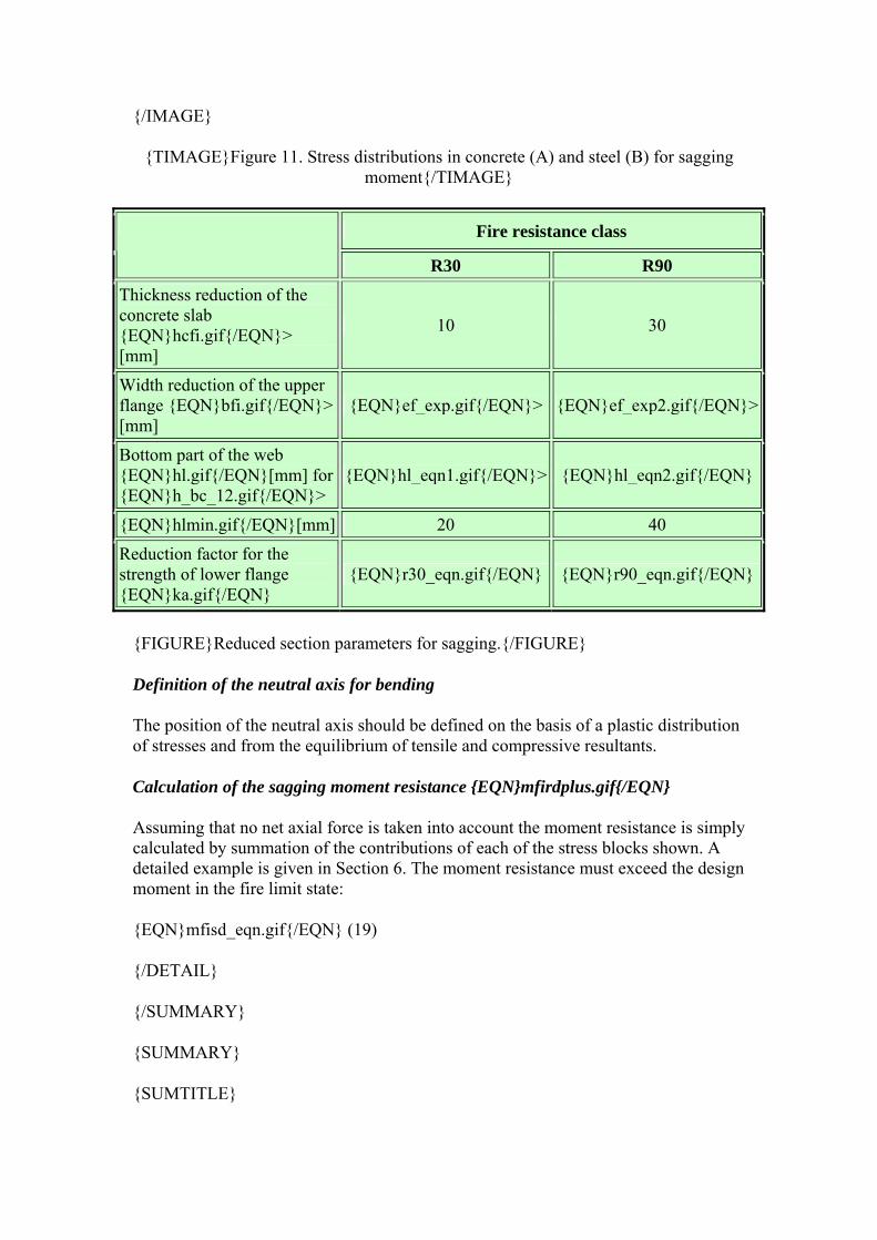
{TIMAGE}Figure 11. Stress distributions in concrete (A) and steel (B) for sagging moment{/TIMAGE}
Fire resistance class
R30 R90 Thickness reduction of the concrete slab {EQN}hcfi.gif{/EQN}> [mm]
10 30
Width reduction of the upper flange {EQN}bfi.gif{/EQN}> [mm]
{EQN}ef_exp.gif{/EQN}> {EQN}ef_exp2.gif{/EQN}>
Bottom part of the web {EQN}hl.gif{/EQN}[mm] for {EQN}h_bc_12.gif{/EQN}>
{EQN}hl_eqn1.gif{/EQN}> {EQN}hl_eqn2.gif{/EQN}
{EQN}hlmin.gif{/EQN}[mm] 20 40
Reduction factor for the strength of lower flange {EQN}ka.gif{/EQN}
{EQN}r30_eqn.gif{/EQN} {EQN}r90_eqn.gif{/EQN}
{FIGURE}Reduced section parameters for sagging.{/FIGURE}
Definition of the neutral axis for bending
The position of the neutral axis should be defined on the basis of a plastic distribution of stresses and from the equilibrium of tensile and compressive resultants.
Calculation of the sagging moment resistance {EQN}mfirdplus.gif{/EQN}
Assuming that no net axial force is taken into account the moment resistance is simply calculated by summation of the contributions of each of the stress blocks shown. A detailed example is given in Section 6. The moment resistance must exceed the design moment in the fire limit state:
{EQN}mfisd_eqn.gif{/EQN} (19)
{/DETAIL}
{/SUMMARY}
{SUMMARY}
{SUMTITLE}
Hogging moment resistance Mfi,Rd-
{/SUMTITLE}
In hogging zones the reinforcement acting in tension within the effective thickness of the concrete flange is considered, with a temperature reduction depending on its position, but the effective width of the flange is reduced. The upper flange of the steel section is again given full strength but loses its heat-affected edge regions, while the lower flange is ignored. The steel web does not contribute to moment resistance but carries the shear force. The strength reduction for reinforcing bars is calculated using a function of their distances from the heated surfaces.
{IMAGE}
hogging_partial_encase.gif
{/IMAGE}
{PPT}
Lecture11bHogging.pps
{/PPT}
{DETAIL}
The calculation method is the same as that for sagging moment resistance, except for some differences in definition of the reduced section.
{IMAGE}
L11Image38.gif
{/IMAGE}
{TIMAGE}Figure 12. Stress distribution in concrete (A) and steel (B) for hogging moment{/TIMAGE}
Concrete slab and reinforcement
Concrete in tension is excluded from the calculation, but the tensile reinforcement lying in the effective area is taken into account. The effective width of the concrete slab is reduced to three times the width of the steel profile. The temperature and the strength reduction depends on the distance {EQN}u.gif{/EQN} of the reinforcing bars from the lower slab edge. The reduction factor {EQN}ks.gif{/EQN} of the yield point of the reinforcing bars in the concrete slab is given as a function of the distance {EQN}u.gif{/EQN}. Two examples of the factor {EQN}ks.gif{/EQN} are shown in the table below.
Upper flange of steel section
The same rules are adopted as in calculation of sagging moment resistance. In the case of a simply supported beam, which is assumed to be continuous in the fire situation, the upper flange should not be taken into account if it is in tension.
Concrete between the flanges
Concrete infill between flanges is considered to have its full compressive strength but to have a reduced cross-section. The appropriate reductions of height {EQN}hfi.gif{/EQN} and width {EQN}bfi.gif{/EQN} are given in {ECLINK}EC4 Part 1.2{/ECLINK}. Some examples, including minimum values, are shown in the table.
Reinforcement between flanges
The rules used in calculating the sagging moment resistance should be adopted.
Steel web
In areas of hogging bending moment the shear force is assumed to be transmitted by the steel web, which is neglected when calculating the hogging bending moment resistance.
Lower flange
For the purpose of calculation of hogging moment resistance the compressed lower flange should be ignored.
Reduction of the concrete {EQN}hfi.gif{/EQN}[mm] 25 {EQN}r90_eqn2.gif{/EQN}
{EQN}hfimin.gif{/EQN}[mm] 25 45
Reduction of the concrete {EQN}bcfi.gif{/EQN}[mm] 25 {EQN}r90_eqn3.gif{/EQN}
{EQN}bcfimin.gif{/EQN}[mm] 25 35
{FIGURE}Reduced section parameters for hogging{/FIGURE}
{/DETAIL}
{/SUMMARY}
{TEST}
{TTITLE} Moment Resistance of Partially Encased Beams{/TTITLE}
{QUESTION}
{QTITLE}Sagging resistance: concrete
{/QTITLE}
{QTYPE}MC{/QTYPE}
{QTEXT}
In following question select the correct answers (more than one answer may be correct).
Select the parts of the concrete cross-section, which are taken into account when calculating sagging moment resistance according to EC4 Part 1.2 .
{IMAGE}
part_encase_q1.gif
{/IMAGE}
{/QTEXT}
{ANSWER} a) the whole part 1 with reduced strength
{CHECKMARK}0{/CHECKMARK}
{CHECK}No{/CHECK}
{UNCHECKMARK}10{/UNCHECKMARK}
{UNCHECK}No{/UNCHECK}
{/ANSWER}
{ANSWER} b) the whole part 1 with full strength
{CHECKMARK}0{/CHECKMARK}
{CHECK}No{/CHECK}
{UNCHECKMARK}10{/UNCHECKMARK}
{UNCHECK}No{/UNCHECK}
{/ANSWER}
{ANSWER} c) a portion of part 1 with reduced strength
{CHECKMARK}0{/CHECKMARK}
{CHECK}No{/CHECK}
{UNCHECKMARK}10{/UNCHECKMARK}
{UNCHECK}No{/UNCHECK}
{/ANSWER}
{ANSWER} d) a portion of part 1 with full strength
{CHECKMARK}30{/CHECKMARK}
{CHECK}Yes{/CHECK}
{UNCHECKMARK}0{/UNCHECKMARK}
{UNCHECK}Yes{/UNCHECK}
{/ANSWER}
{ANSWER} e) the whole part 2 with reduced strength
{CHECKMARK}0{/CHECKMARK}
{CHECK}No{/CHECK}
{UNCHECKMARK}10{/UNCHECKMARK}
{UNCHECK}No{/UNCHECK}
{/ANSWER}
{ANSWER} f) the whole part 2 with full strength
{CHECKMARK}0{/CHECKMARK}
{CHECK}No{/CHECK}
{UNCHECKMARK}10{/UNCHECKMARK}
{UNCHECK}No{/UNCHECK}
{/ANSWER}
{ANSWER} g) a portion of part 2 with reduced strength
{CHECKMARK}0{/CHECKMARK}
{CHECK}No{/CHECK}
{UNCHECKMARK}10{/UNCHECKMARK}
{UNCHECK}No{/UNCHECK}
{/ANSWER}
{ANSWER} h) a portion of part 2 with full strength
{CHECKMARK}0{/CHECKMARK}
{CHECK}No{/CHECK}
{UNCHECKMARK}10{/UNCHECKMARK}
{UNCHECK}No{/UNCHECK}
{/ANSWER}
{FEEDBACK}
Part 1 - in this case concrete slab is wholly in compresion. Only parts not influenced by heat (within the depth hc - hc,fi and a small part above the effective width of the steel flange) are taken into account with full strength.
Part 2 is in tension, so it is not included in the calculations.
{/FEEDBACK}
{/QUESTION}
{QUESTION}
{QTITLE}Sagging resistance: steel section
{/QTITLE}
{QTYPE}MC{/QTYPE}
{QTEXT}
In following question select the correct answers (more than one answer may be correct).
Select the parts of the steel profile, which are taken into account when calculating sagging moment resistance according to EC4 Part 1.2 :
{IMAGE}
part_encase_q2.gif
{/IMAGE}
{/QTEXT}
{ANSWER} a) the whole part 1 with reduced strength
{CHECKMARK}0{/CHECKMARK}
{CHECK}No{/CHECK}
{UNCHECKMARK}1{/UNCHECKMARK}
{UNCHECK}No{/UNCHECK}
{/ANSWER}
{ANSWER} b) the whole part 1 with full strength
{CHECKMARK}0{/CHECKMARK}
{CHECK}No{/CHECK}
{UNCHECKMARK}1{/UNCHECKMARK}
{UNCHECK}No{/UNCHECK}
{/ANSWER}
{ANSWER} c) a portion of part 1 with reduced strength
{CHECKMARK}0{/CHECKMARK}
{CHECK}No{/CHECK}
{UNCHECKMARK}1{/UNCHECKMARK}
{UNCHECK}No{/UNCHECK}
{/ANSWER}
{ANSWER} d) a portion of part 1 with full strength
{CHECKMARK}1{/CHECKMARK}
{CHECK}Yes{/CHECK}
{UNCHECKMARK}0{/UNCHECKMARK}
{UNCHECK}Yes{/UNCHECK}
{/ANSWER}
{ANSWER} e) the whole part 2 with reduced strength
{CHECKMARK}0{/CHECKMARK}
{CHECK}No{/CHECK}
{UNCHECKMARK}1{/UNCHECKMARK}
{UNCHECK}No{/UNCHECK}
{/ANSWER}
{ANSWER} f) the whole part 2 with full strength
{CHECKMARK}0{/CHECKMARK}
{CHECK}No{/CHECK}
{UNCHECKMARK}1{/UNCHECKMARK}
{UNCHECK}No{/UNCHECK}
{/ANSWER}
{ANSWER} g) the upper half of part 2 with reduced strength and the lower part with reduced section
{CHECKMARK}0{/CHECKMARK}
{CHECK}No{/CHECK}
{UNCHECKMARK}1{/UNCHECKMARK}
{UNCHECK}No{/UNCHECK}
{/ANSWER}
{ANSWER} h) the upper half of part 2 with full strength and the lower part with reduced strength
{CHECKMARK}0{/CHECKMARK}
{CHECK}No{/CHECK}
{UNCHECKMARK}1{/UNCHECKMARK}
{UNCHECK}No{/UNCHECK}
{/ANSWER}
{ANSWER} i) part 2 partially with full strength and partially with linearly reduced strength
{CHECKMARK}1{/CHECKMARK}
{CHECK}Yes{/CHECK}
{UNCHECKMARK}0{/UNCHECKMARK}
{UNCHECK}Yes{/UNCHECK}
{/ANSWER}
{ANSWER} j) the whole part 3 with reduced strength
{CHECKMARK}1{/CHECKMARK}
{CHECK}Yes{/CHECK}
{UNCHECKMARK}0{/UNCHECKMARK}
{UNCHECK}Yes{/UNCHECK}
{/ANSWER}
{ANSWER} k) the whole part 3 with full strength
{CHECKMARK}0{/CHECKMARK}
{CHECK}No{/CHECK}
{UNCHECKMARK}1{/UNCHECKMARK}
{UNCHECK}No{/UNCHECK}
{/ANSWER}
{ANSWER} l) a portion of part 3 with reduced strength
{CHECKMARK}0{/CHECKMARK}
{CHECK}No{/CHECK}
{UNCHECKMARK}1{/UNCHECKMARK}
{UNCHECK}No{/UNCHECK}
{/ANSWER}
{ANSWER} m) a portion of part 3 with full strength
{CHECKMARK}0{/CHECKMARK}
{CHECK}No{/CHECK}
{UNCHECKMARK}1{/UNCHECKMARK}
{UNCHECK}No{/UNCHECK}
{/ANSWER}
{FEEDBACK}
Part 1 - the upper flange of the steel profile is not heated uniformly. Only the edges are affected by the temperature, so it is assumed to have reduced section and full strength
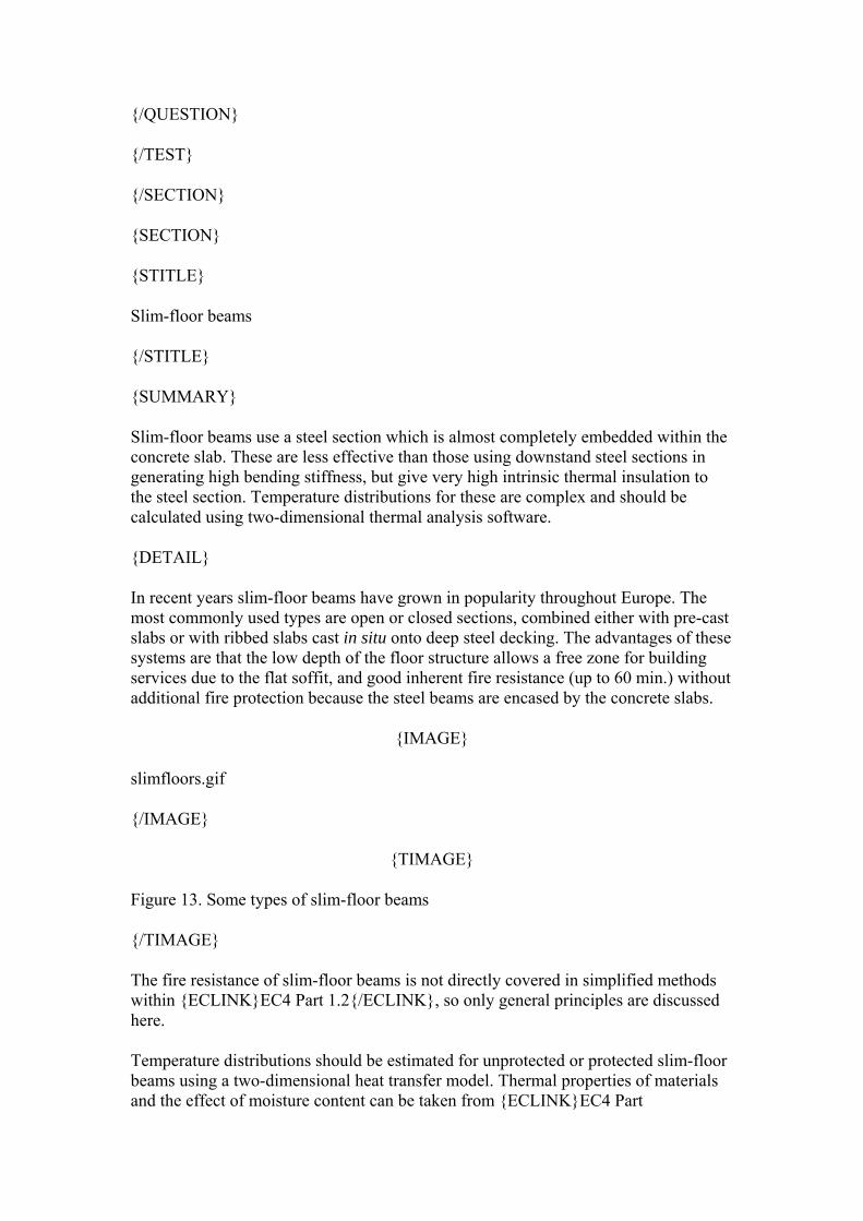
Part 2 - the steel web is divided into two parts depending on the fire resistance class. The upper part is assumed to remain at 20°C, so its full strength is used. In the lower part the temperature, and therefore also the strength, is assumed to change linearly.
Part 3 - the lower flange of the steel profile is heated uniformly and so it is fully influenced by heat; therefore it is taken into account with reduced strength and full section.
{/FEEDBACK}
{/QUESTION}
{QUESTION}
{QTITLE}Concrete infill
{/QTITLE}
{QTYPE}MC{/QTYPE}
{QTEXT}
When calculating the sagging moment resistance, the concrete between flanges is generally in tension, so it fulfils only an insulation function – True or False?
{/QTEXT}
{ANSWER}True
{CHECKMARK}0{/CHECKMARK}
{CHECK}No{/CHECK}
{UNCHECKMARK}1{/UNCHECKMARK}
{UNCHECK}No{/UNCHECK}
{/ANSWER}
{ANSWER}False
{CHECKMARK}1{/CHECKMARK}
{CHECK}Yes{/CHECK}
{UNCHECKMARK}0{/UNCHECKMARK}
{UNCHECK}Yes{/UNCHECK}
{/ANSWER}
{FEEDBACK}
Although the concrete between the steel flanges is in tension, it is assumed to resist the vertical shear by itself, so its shear resistance must be verified.
{/FEEDBACK}
{/QUESTION}
{QUESTION}
{QTITLE}Neutral axis position
{/QTITLE}
{QTYPE}MC{/QTYPE}
{QTEXT}
The position of the neutral axis should be calculated from the equilibrium of statical moments of the area - True or False?
{/QTEXT}
{ANSWER}True
{CHECKMARK}0{/CHECKMARK}
{CHECK}No{/CHECK}
{UNCHECKMARK}1{/UNCHECKMARK}
{UNCHECK}No{/UNCHECK}
{/ANSWER}
{ANSWER}False
{CHECKMARK}1{/CHECKMARK}
{CHECK}Yes{/CHECK}
{UNCHECKMARK}0{/UNCHECKMARK}
{UNCHECK}Yes{/UNCHECK}
{/ANSWER}
{FEEDBACK}
Plastic theory is used so the position of the neutral axis should be defined from the equilibrium of tensile and compressive resultants.
{/FEEDBACK}
{/QUESTION}
{QUESTION}
{QTITLE}Hogging resistance: concrete
{/QTITLE}
{QTYPE}MC{/QTYPE}
{QTEXT}
In following question select the correct answers (more than one answer may be correct).
Mark the parts of the concrete cross-section shown, which are taken into account when calculating hogging moment resistance according to EC4 Part 1.2 .
{IMAGE}
part_encase_q1.gif
{/IMAGE}
{/QTEXT}
{ANSWER} a) the whole part 1 with reduced strength
{CHECKMARK}0{/CHECKMARK}
{CHECK}No{/CHECK}
{UNCHECKMARK}1{/UNCHECKMARK}
{UNCHECK}No{/UNCHECK}
{/ANSWER}
{ANSWER} b) the whole part 1 with full strength
{CHECKMARK}0{/CHECKMARK}
{CHECK}No{/CHECK}
{UNCHECKMARK}1{/UNCHECKMARK}
{UNCHECK}No{/UNCHECK}
{/ANSWER}
{ANSWER} c) a portion of part 1 with reduced strength
{CHECKMARK}0{/CHECKMARK}
{CHECK}No{/CHECK}
{UNCHECKMARK}1{/UNCHECKMARK}
{UNCHECK}No{/UNCHECK}
{/ANSWER}
{ANSWER} d) a portion of part 1 with full strength
{CHECKMARK}0{/CHECKMARK}
{CHECK}No{/CHECK}
{UNCHECKMARK}1{/UNCHECKMARK}
{UNCHECK}No{/UNCHECK}
{/ANSWER}
{ANSWER} e) the whole part 2 with reduced strength
{CHECKMARK}0{/CHECKMARK}
{CHECK}No{/CHECK}
{UNCHECKMARK}1{/UNCHECKMARK}
{UNCHECK}No{/UNCHECK}
{/ANSWER}
{ANSWER} f) the whole part 2 with full strength
{CHECKMARK}0{/CHECKMARK}
{CHECK}No{/CHECK}
{UNCHECKMARK}1{/UNCHECKMARK}
{UNCHECK}No{/UNCHECK}
{/ANSWER}
{ANSWER} g) a portion of part 2 with reduced strength
{CHECKMARK}0{/CHECKMARK}
{CHECK}No{/CHECK}
{UNCHECKMARK}1{/UNCHECKMARK}
{UNCHECK}No{/UNCHECK}
{/ANSWER}
{ANSWER} h) a portion of part 2 with full strength
{CHECKMARK}1{/CHECKMARK}
{CHECK}Yes{/CHECK}
{UNCHECKMARK}0{/UNCHECKMARK}
{UNCHECK}Yes{/UNCHECK}
{/ANSWER}
{FEEDBACK}
Part 1 - The concrete slab is in tension so it is neglected, but the tensile reinforcement in the effective area is taken into account.
Part 2 - The concrete between the steel flanges is in compression and is not heated uniformly, so it is considered as having a reduced cross-section and full strength.
{/FEEDBACK}
{/QUESTION}
{QUESTION}
{QTITLE}Hogging resistance: steel section
{/QTITLE}
{QTYPE}MC{/QTYPE}
{QTEXT}
Select the parts of steel profile shown, which are taken into account when calculating hogging moment resistance according to EC4 Part 1.2.
{IMAGE}
part_encase_q2.gif
{/IMAGE}
{/QTEXT}
{ANSWER} a) the whole of part 1 with reduced strength
{CHECKMARK}0{/CHECKMARK}
{CHECK}No{/CHECK}
{UNCHECKMARK}1{/UNCHECKMARK}
{UNCHECK}No{/UNCHECK}
{/ANSWER}
{ANSWER} b) the whole of part 1 with full strength
{CHECKMARK}0{/CHECKMARK}
{CHECK}No{/CHECK}
{UNCHECKMARK}1{/UNCHECKMARK}
{UNCHECK}No{/UNCHECK}
{/ANSWER}
{ANSWER} c) a portion of part 1 with reduced strength
{CHECKMARK}0{/CHECKMARK}
{CHECK}No{/CHECK}
{UNCHECKMARK}1{/UNCHECKMARK}
{UNCHECK}No{/UNCHECK}
{/ANSWER}
{ANSWER} d) a portion of part 1 with full strength
{CHECKMARK}1{/CHECKMARK}
{CHECK}Yes{/CHECK}
{UNCHECKMARK}0{/UNCHECKMARK}
{UNCHECK}Yes{/UNCHECK}
{/ANSWER}
{ANSWER} e) the whole of part 2 with reduced strength
{CHECKMARK}0{/CHECKMARK}
{CHECK}No{/CHECK}
{UNCHECKMARK}1{/UNCHECKMARK}
{UNCHECK}No{/UNCHECK}
{/ANSWER}
{ANSWER} f) the whole of part 2 with full strength
{CHECKMARK}0{/CHECKMARK}
{CHECK}No{/CHECK}
{UNCHECKMARK}1{/UNCHECKMARK}
{UNCHECK}No{/UNCHECK}
{/ANSWER}
{ANSWER} g) the upper half of part 2 with reduced strength and the lower part with reduced section
{CHECKMARK}0{/CHECKMARK}
{CHECK}No{/CHECK}
{UNCHECKMARK}1{/UNCHECKMARK}
{UNCHECK}No{/UNCHECK}
{/ANSWER}
{ANSWER} h) the upper half of part 2 with full strength and the lower part with reduced strength
{CHECKMARK}0{/CHECKMARK}
{CHECK}No{/CHECK}
{UNCHECKMARK}1{/UNCHECKMARK}
{UNCHECK}No{/UNCHECK}
{/ANSWER}
{ANSWER} i) part 2, partially with full strength and partially with linearly reduced strength
{CHECKMARK}0{/CHECKMARK}
{CHECK}No{/CHECK}
{UNCHECKMARK}1{/UNCHECKMARK}
{UNCHECK}No{/UNCHECK}
{/ANSWER}
{ANSWER} j) the whole of part 3 with reduced strength
{CHECKMARK}0{/CHECKMARK}
{CHECK}No{/CHECK}
{UNCHECKMARK}1{/UNCHECKMARK}
{UNCHECK}No{/UNCHECK}
{/ANSWER}
{ANSWER} k) the whole of part 3 with full strength
{CHECKMARK}0{/CHECKMARK}
{CHECK}No{/CHECK}
{UNCHECKMARK}1{/UNCHECKMARK}
{UNCHECK}No{/UNCHECK}
{/ANSWER}
{ANSWER} l) a portion of part 3 with reduced strength
{CHECKMARK}0{/CHECKMARK}
{CHECK}No{/CHECK}
{UNCHECKMARK}1{/UNCHECKMARK}
{UNCHECK}No{/UNCHECK}
{/ANSWER}
{ANSWER} m) a portion of part 3 with full strength
{CHECKMARK}0{/CHECKMARK}
{CHECK}No{/CHECK}
{UNCHECKMARK}1{/UNCHECKMARK}
{UNCHECK}No{/UNCHECK}
{/ANSWER}
{FEEDBACK}
Part 1 - The upper flange of the steel profile is not heated uniformly; only the edges are affected by the temperature, so it is assumed to have reduced section and full strength.
Part 2 - The steel web is in compression and is assumed to transmit the shear force, so it is neglected when calculating the hogging bending moment resistance.
Part 3 - The lower flange of the steel profile is compressed. It is not taken into account when calculating hogging moment resistance.
{/FEEDBACK}
{/QUESTION}
{QUESTION}
{QTITLE}Hogging resistance: reinforcement
{/QTITLE}
{QTYPE}MC{/QTYPE}
{QTEXT}
The reinforcement between the flanges is in compression in the zone of hogging moment, so because it could buckle it is excluded from calculations. True or False?
{/QTEXT}
{ANSWER}True
{CHECKMARK}0{/CHECKMARK}
{CHECK}No{/CHECK}
{UNCHECKMARK}1{/UNCHECKMARK}
{UNCHECK}No{/UNCHECK}
{/ANSWER}
{ANSWER}False
{CHECKMARK}1{/CHECKMARK}
{CHECK}Yes{/CHECK}
{UNCHECKMARK}0{/UNCHECKMARK}
{UNCHECK}Yes{/UNCHECK}
{/ANSWER}
{FEEDBACK}
If the stirrups are designed according to EC2 Part 1.1 to prevent the buckling of reinforcement, the reinforcing bars are taken into account when calculating hogging moment resistance.
{/FEEDBACK}
{/QUESTION}
{QUESTION}
{QTITLE}Effective width
{/QTITLE}
{QTYPE}MC{/QTYPE}
{QTEXT}
Since plastic theory is used, the effective width of the concrete slab is assumed constant along the composite beam and is given by beff = ((equivalent span/8)x2+b0). True or False?
{/QTEXT}
{ANSWER}True
{CHECKMARK}0{/CHECKMARK}
{CHECK}No{/CHECK}
{UNCHECKMARK}1{/UNCHECKMARK}
{UNCHECK}No{/UNCHECK}
{/ANSWER}
{ANSWER}False
{CHECKMARK}1{/CHECKMARK}
{CHECK}Yes{/CHECK}
{UNCHECKMARK}0{/UNCHECKMARK}
{UNCHECK}Yes{/UNCHECK}
{/ANSWER}
{FEEDBACK}
This is true only in the region of sagging bending moment. In the hogging region the effective width of the concrete slab is reduced to three times the width of the steel profile, and only tensile reinforcement in this area is taken into account.
{/FEEDBACK}
{/QUESTION}
{/TEST}
{/SECTION}
{SECTION}
{STITLE}
Slim-floor beams
{/STITLE}
{SUMMARY}
Slim-floor beams use a steel section which is almost completely embedded within the concrete slab. These are less effective than those using downstand steel sections in generating high bending stiffness, but give very high intrinsic thermal insulation to the steel section. Temperature distributions for these are complex and should be calculated using two-dimensional thermal analysis software.
{DETAIL}
In recent years slim-floor beams have grown in popularity throughout Europe. The most commonly used types are open or closed sections, combined either with pre-cast slabs or with ribbed slabs cast in situ onto deep steel decking. The advantages of these systems are that the low depth of the floor structure allows a free zone for building services due to the flat soffit, and good inherent fire resistance (up to 60 min.) without additional fire protection because the steel beams are encased by the concrete slabs.
{IMAGE}
slimfloors.gif
{/IMAGE}
{TIMAGE}
Figure 13. Some types of slim-floor beams
{/TIMAGE}
The fire resistance of slim-floor beams is not directly covered in simplified methods within {ECLINK}EC4 Part 1.2{/ECLINK}, so only general principles are discussed here.
Temperature distributions should be estimated for unprotected or protected slim-floor beams using a two-dimensional heat transfer model. Thermal properties of materials and the effect of moisture content can be taken from {ECLINK}EC4 Part
1.2{/ECLINK}, and heat flux should be determined by considering thermal radiation and convection. When the temperature distribution over the cross-section is known, the resistance of the slim-floor beam in the fire limit state can be calculated using the moment capacity method either for composite or non-composite beams, with reduction factors for steel and concrete strength taken from {ECLINK}EC4 Part 1.2{/ECLINK}. In order to calculate the bending resistance, the section is divided to several components: the plate and/or the bottom flange, the lower web, the upper web, the upper flange, reinforcing bars and the concrete slab. Concrete in tension is ignored and, as the neutral axis is in most cases very close to the upper flange, the temperature of the concrete in compression can be assumed to be below 100°C.
{PPT}
Lecture11bSlimFloor.pps
{/PPT}
{/DETAIL}
{/SUMMARY}
{/SECTION}
{SECTION}
{STITLE}
Composite columns
{/STITLE}
{SUMMARY}
Columns in a fire-affected storey which are continuous into cooler storeys above and below are considered to be fully restrained against rotation at these ends in estimating their buckling lengths. The reduction factors for strength and modulus at high temperatures are applied in calculating the buckling resistances.
{IMAGE}
compo_cols.gif
{/IMAGE}
{PPT}
Lecture11bColumns.pps
{/PPT}
{DETAIL}
The simplified rules given in {ECLINK}EC4 Part 1.2{/ECLINK} are valid only for braced frames. Provided that a fire is limited to a single storey, and that the fire-affected columns are fully connected to the colder columns below and above, it is possible to assume that their ends are rotationally restrained so that the buckling length in the fire situation is estimated assuming fixed ends. This means that for intermediate storeys the buckling length in fire is {EQN}lficr_eqn2.gif{/EQN} and for the top floor (or for a ground floor with pinned base connection) {EQN}lficr_eqn1.gif{/EQN}.
{IMAGE}
buckling_lengths.gif
{/IMAGE}
{TIMAGE}
Figure 14. Buckling lengths in fire
{/TIMAGE}
In the simple calculation model the buckling resistance in fire is obtained from:
{EQN}nfirdz_eqn.gif{/EQN}
where
{EQN}chiz.gif{/EQN}is the reduction coefficient for buckling about the minor axis z, evaluated according to rules of {ECLINK}EC3 Part 1.1{/ECLINK}, but using only buckling curve (c) to relate it to the non-dimensional slenderness ratio {EQN}lamdabarztheta.gif{/EQN},
{EQN}nfiplrd.gif{/EQN} is the design value of the plastic resistance to axial compression in the fire situation.
The non-dimensional slenderness ratio{EQN}lamdabarztheta.gif{/EQN}is given by:
{EQN}lamdabarztheta_eqn.gif{/EQN} (20)
where{EQN}nfiplr.gif{/EQN}is the value of{EQN}nfiplrd.gif{/EQN}when the factors{EQN}gammamfia.gif{/EQN},{EQN}gammamfis.gif{/EQN} and{EQN}gammamfic.gif{/EQN}are taken as 1,0 and{EQN}nficrz.gif{/EQN}is the Euler critical buckling load for the fire situation, obtained from
{EQN}nficrz_eqn.gif{/EQN} (21)
In this equation the buckling length{EQN}ltheta.gif{/EQN}in the fire situation is obtained according to the figure, and {EQN}eifieffz.gif{/EQN} is the flexural stiffness of the cross-section in the fire situation.
In the more detailed calculation rules given by {ECLINK}EC4 Part 1.2{/ECLINK} there are some differences between their application to different types of cross-section. The code gives methods for the analysis of two basic types:
• Steel sections with partial concrete encasement (unprotected and protected), • Concrete-filled circular and square hollow sections (unprotected and
protected).
{/DETAIL}
{/SUMMARY}
{SUMMARY}
{SUMTITLE}
Steel section with partial concrete encasement
{/SUMTITLE}
A partially encased column consists of a steel H-section with concrete infill, which may be reinforced, between the flanges. In calculating the reduced strength and elastic stiffness the flanges are assumed to have uniform temperature. The ends of the web, and the outer portions of the concrete infill, are ignored. The temperatures of the steel section components and the remaining concrete core, depend on the fire resistance rating required.
{DETAIL}
There are some restrictions to the use of the simple calculation model given in {ECLINK}EC4 Part 1.2{/ECLINK}
• Buckling length {EQN}ltheta_eqn.gif{/EQN} • Depth of cross-section{EQN}h.gif{/EQN}is between 230mm and 1100mm, • Width of cross-section{EQN}b.gif{/EQN}is between 230mm and 500mm, • Minimum{EQN}h.gif{/EQN}and{EQN}b.gif{/EQN}for R90 and R120 is
300mm, • Percentage of reinforcing steel is between 1% and 6%, • Standard fire resistance period is up to 120 min.
To determine the axial plastic resistance{EQN}nfiplrd.gif{/EQN} and the flexural stiffness{EQN}eifieffz.gif{/EQN}in the fire situation, the cross-section is divided into: the flanges of the steel section, the web of the steel section, the reinforcing bars and the concrete infill between the flanges. {ECLINK}EC4 Part 1.2{/ECLINK}
{IMAGE}Division_of_the_cross-section.gif{/IMAGE}
{TIMAGE}Figure 15. Division of the column cross-section{/TIMAGE}
For each of these components the temperature for the required standard fire resistance (R30, R60, R90 or R120) is estimated. A reduced strength and modulus of elasticity is then determined as a function of temperature. In the simple calculation model a uniform temperature distribution is assumed over certain elements, but in case of the steel web and the concrete infill the outer parts have a considerably higher temperature and thus a high thermal gradient occurs. Because of this the sections of the steel web and the concrete infill are reduced, with the outer parts ({EQN}hwfi.gif{/EQN}and{EQN}bcfi.gif{/EQN}) being ignored.
The process for fire engineering design of partially encased composite steel and concrete columns, in the context of braced frames, may be summarised as follows:
{PPT}
Lecture11bPartEncaseCols.pps
{/PPT}
{/DETAIL}
{/SUMMARY}
{SUMMARY}
{SUMTITLE}
The fire engineering design process
{/SUMTITLE}
The axial plastic resistance and the effective flexural stiffness at the required fire resistance time are calculated using the effective cross-section and the reduced mechanical properties of each of its component parts.
{IMAGE}
L11Image47.gif
{/IMAGE}
{PPT}
Lecture11bColDesign.pps
{/PPT}
{DETAIL}
When this is done the process of calculating the column’s buckling resistance at the required time follows closely the normal ambient-temperature procedure.
Process Calculation
Plastic resistance to axial compression {EQN}colprocess1.gif{/EQN}
Non-dimensional slenderness ratio {EQN}colprocess5.gif{/EQN}
Strength reduction{EQN}chiz.gif{/EQN}for
Curve "c"
Buckling resistance {EQN}colprocess6.gif{/EQN}
Is resistance > loading ??? {EQN}colprocess7.gif{/EQN}
Eccentricity of loading
In the case of eccentric loading the application point should remain inside the composite section of the column. The design buckling load for eccentricity{EQN}delta.gif{/EQN}is then obtained from {ECLINK}EC4 Part 1.2{/ECLINK}:
{EQN}nfirddelta.gif{/EQN} (22)
where {EQN}nrd.gif{/EQN} and {EQN}nrddelta.gif{/EQN} are the values of the axial buckling resistance and buckling resistance for the case of eccentric loading for normal temperature design, and are calculated according to {ECLINK}EC4 Part 1.1{/ECLINK}.
{/DETAIL}
{/SUMMARY}
{TEST}
{TTITLE}Composite Columns
{/TTITLE}
{QUESTION}
{QTITLE}
Validity of rules for columns
{/QTITLE}
{QTYPE}MC{/QTYPE}
{QTEXT}
The simplified rules given in EC4 Part 1.2 are valid for these types of columns (more than one correct answer is possible):
{/QTEXT}
{ANSWER} a) Steel section with total concrete encasement
{CHECKMARK}0{/CHECKMARK}
{CHECK}No{/CHECK}
{UNCHECKMARK}1{/UNCHECKMARK}
{UNCHECK}No{/UNCHECK}
{/ANSWER}
{ANSWER} b) Unprotected steel sections with partial concrete encasement (all types of steel section with some restrictions)
{CHECKMARK}0{/CHECKMARK}
{CHECK}No{/CHECK}
{UNCHECKMARK}1{/UNCHECKMARK}
{UNCHECK}No{/UNCHECK}
{/ANSWER}
{ANSWER} c) Unprotected steel sections with partial concrete encasement (double steel T-sections with some restrictions)
{ANSWER} e) Protected steel sections with partial concrete encasement
{CHECKMARK}1{/CHECKMARK}
{CHECK}Yes{/CHECK}
{UNCHECKMARK}0{/UNCHECKMARK}
{UNCHECK}Yes{/UNCHECK}
{/ANSWER}
{ANSWER} f) Unprotected concrete-filled circular and square hollow sections
{CHECKMARK}1{/CHECKMARK}
{CHECK}Yes{/CHECK}
{UNCHECKMARK}0{/UNCHECKMARK}
{UNCHECK}Yes{/UNCHECK}
{/ANSWER}
{ANSWER} g) Protected concrete-filled circular and square hollow sections
{CHECKMARK}1{/CHECKMARK}
{CHECK}Yes{/CHECK}
{UNCHECKMARK}0{/UNCHECKMARK}
{UNCHECK}Yes{/UNCHECK}
{/ANSWER}
{FEEDBACK}
{/FEEDBACK}
{/QUESTION}
{QUESTION}
{QTITLE}
Modelling of column cross-sections
{/QTITLE}
{QTYPE}MC{/QTYPE}
{QTEXT}
When calculating the axial plastic resistance and the flexural stiffness in the fire situation according to{ECLINK}EC4 Part 1.2{/ECLINK}the following parts of the cross-section are taken into account:
{/QTEXT}
{ANSWER} a) The steel flanges with reduced strength and full cross-section
{CHECKMARK}1{/CHECKMARK}
{CHECK}Yes{/CHECK}
{UNCHECKMARK}0{/UNCHECKMARK}
{UNCHECK}Yes{/UNCHECK}
{/ANSWER}
{ANSWER} b) The steel flanges with reduced strength and reduced cross-section
{CHECKMARK}0{/CHECKMARK}
{CHECK}No{/CHECK}
{UNCHECKMARK}1{/UNCHECKMARK}
{UNCHECK}No{/UNCHECK}
{/ANSWER}
{ANSWER} c) The steel web with reduced strength and full cross-section
{CHECKMARK}0{/CHECKMARK}
{CHECK}No{/CHECK}
{UNCHECKMARK}1{/UNCHECKMARK}
{UNCHECK}No{/UNCHECK}
{/ANSWER}
{ANSWER} d) The steel web with full strength and full cross-section
{CHECKMARK}0{/CHECKMARK}
{CHECK}No{/CHECK}
{UNCHECKMARK}1{/UNCHECKMARK}
{UNCHECK}No{/UNCHECK}
{/ANSWER}
{ANSWER} e) The steel web with full strength and reduced cross-section
{CHECKMARK}0{/CHECKMARK}
{CHECK}No{/CHECK}
{UNCHECKMARK}1{/UNCHECKMARK}
{UNCHECK}No{/UNCHECK}
{/ANSWER}
{ANSWER} f) The steel web with reduced strength and reduced cross-section
{CHECKMARK}1{/CHECKMARK}
{CHECK}Yes{/CHECK}
{UNCHECKMARK}0{/UNCHECKMARK}
{UNCHECK}Yes{/UNCHECK}
{/ANSWER}
{ANSWER} g) The concrete between flanges with full strength and full cross-section
{CHECKMARK}0{/CHECKMARK}
{CHECK}No{/CHECK}
{UNCHECKMARK}1{/UNCHECKMARK}
{UNCHECK}No{/UNCHECK}
{/ANSWER}
{ANSWER} h) The concrete between flanges with reduced strength and full cross-section
{CHECKMARK}0{/CHECKMARK}
{CHECK}No{/CHECK}
{UNCHECKMARK}1{/UNCHECKMARK}
{UNCHECK}No{/UNCHECK}
{/ANSWER}
{ANSWER} i) The concrete between flanges with full strength and reduced cross-section
{CHECKMARK}0{/CHECKMARK}
{CHECK}No{/CHECK}
{UNCHECKMARK}1{/UNCHECKMARK}
{UNCHECK}No{/UNCHECK}
{/ANSWER}
{ANSWER} j) The concrete between flanges with reduced strength and reduced cross-section
{CHECKMARK}1{/CHECKMARK}
{CHECK}Yes{/CHECK}
{UNCHECKMARK}0{/UNCHECKMARK}
{UNCHECK}Yes{/UNCHECK}
{/ANSWER}
{ANSWER} k) The reinforcement between flanges with reduced strength
{CHECKMARK}0{/CHECKMARK}
{CHECK}No{/CHECK}
{UNCHECKMARK}1{/UNCHECKMARK}
{UNCHECK}No{/UNCHECK}
{/ANSWER}
{ANSWER} l) The reinforcement between flanges with full strength
{CHECKMARK}1{/CHECKMARK}
{CHECK}Yes{/CHECK}
{UNCHECKMARK}0{/UNCHECKMARK}
{UNCHECK}Yes{/UNCHECK}
{/ANSWER}
{FEEDBACK}
Steel flanges and the reinforcement are considered to have full cross-section and reduced strength, depending on the fire resistance class. In the case of the steel web and the concrete infill the outer parts have a considerably higher temperature and thus a high thermal gradient occurs. Because of this the cross-sections of the steel web and the concrete infill are reduced, with the outer parts ({EQN}hwfi.gif{/EQN} and {EQN}bcfi.gif{/EQN} being ignored and the strength of the remaining parts being estimated depending on the fire resistance class.
{/FEEDBACK}
{/QUESTION}
{QUESTION}
{QTITLE}
Critical Length in Fire
{/QTITLE}
{QTYPE}MC{/QTYPE}
{QTEXT}
When estimating the critical length of a column the rules for ambient-temperature design are used except that, in the case of braced frames, for intermediate storeys the buckling length in fire is {EQN}lficr_eqn2.gif{/EQN} and for the top floor (or for a ground floor with pinned base connection) {EQN}lficr_eqn1.gif{/EQN}. True or False?
{/QTEXT}
{ANSWER}True
{CHECKMARK}0{/CHECKMARK}
{CHECK}No{/CHECK}
{UNCHECKMARK}1{/UNCHECKMARK}
{UNCHECK}No{/UNCHECK}
{/ANSWER}
{ANSWER}False
{CHECKMARK}1{/CHECKMARK}
{CHECK}Correct{/CHECK}
{UNCHECKMARK}0{/UNCHECKMARK}
{UNCHECK}Correct{/UNCHECK}
{/ANSWER}
{FEEDBACK}
The simplified rules given in EC4 Part 1.2 are valid only for braced frames.
{/FEEDBACK}
{/QUESTION}
{QUESTION}
{QTITLE}
Buckling Resistance
{/QTITLE}
{QTYPE}MC{/QTYPE}
{QTEXT}
Select 6 parameters which need to be calculated in order to obtain the buckling resistance of a partially encased composite column from The following list:
{/QTEXT}
{ANSWER} a) Non-dimensional stiffness
{CHECKMARK}1{/CHECKMARK}
{CHECK}Yes{/CHECK}
{UNCHECKMARK}0{/UNCHECKMARK}
{UNCHECK}Yes{/UNCHECK}
{/ANSWER}
{ANSWER}b) Temperature distribution in concrete infill
{CHECKMARK}0{/CHECKMARK}
{CHECK}No{/CHECK}
{UNCHECKMARK}1{/UNCHECKMARK}
{UNCHECK}No{/UNCHECK}
{/ANSWER}
{ANSWER}c) Euler critical load
{CHECKMARK}1{/CHECKMARK}
{CHECK}No{/CHECK}
{UNCHECKMARK}0{/UNCHECKMARK}
{UNCHECK}No{/UNCHECK}
{/ANSWER}
{ANSWER}d) H-section cross-sectional area
{CHECKMARK}0{/CHECKMARK}
{CHECK}No{/CHECK}
{UNCHECKMARK}1{/UNCHECKMARK}
{UNCHECK}No{/UNCHECK}
{/ANSWER}
{ANSWER}e) Buckling length
{CHECKMARK}1{/CHECKMARK}
{CHECK}No{/CHECK}
{UNCHECKMARK}0{/UNCHECKMARK}
{UNCHECK}No{/UNCHECK}
{/ANSWER}
{ANSWER}f) Thermal expansion of steel and concrete parts
{CHECKMARK}0{/CHECKMARK}
{CHECK}Yes{/CHECK}
{UNCHECKMARK}1{/UNCHECKMARK}
{UNCHECK}Yes{/UNCHECK}
{/ANSWER}
{ANSWER}g) Residual stresses in steel section
{CHECKMARK}0{/CHECKMARK}
{CHECK}No{/CHECK}
{UNCHECKMARK}1{/UNCHECKMARK}
{UNCHECK}No{/UNCHECK}
{/ANSWER}
{ANSWER}h) Effective flexural stiffness
{CHECKMARK}1{/CHECKMARK}
{CHECK}No{/CHECK}
{UNCHECKMARK}0{/UNCHECKMARK}
{UNCHECK}No{/UNCHECK}
{/ANSWER}
{ANSWER}i) Plastic resistance to axial compression
{CHECKMARK}1{/CHECKMARK}
{CHECK}No{/CHECK}
{UNCHECKMARK}0{/UNCHECKMARK}
{UNCHECK}No{/UNCHECK}
{/ANSWER}
{ANSWER}j) Buckling coefficient
{CHECKMARK}1{/CHECKMARK}
{CHECK}Yes{/CHECK}
{UNCHECKMARK}0{/UNCHECKMARK}
{UNCHECK}Yes{/UNCHECK}
{/ANSWER}
{FEEDBACK}
The factors are: Non-dimensional stiffness, Euler critical load, Critical length, Effective flexural stiffness, Plastic resistance to axial compression, Buckling coefficient.
{/FEEDBACK}
{/QUESTION}
{/TEST}
{/SECTION}
{SECTION}
{STITLE}
Unprotected concrete filled hollow sections
{/STITLE}
{SUMMARY}
Concrete-filled hollow-section columns have increased load capacity because of the enhanced strength of the concrete fill due to confinement, and good fire resistance because of the high level of inherent insulation provided. It is necessary to use numerical modelling software to predict the temperature distributions inside a concrete-filled section, and some guidelines are given for such analysis.
{DETAIL}
Filling the steel hollow sections with concrete has some advantages. It can either be used to increase the load-bearing capacity or reduce of the section size, which increases usable space inside the building, and allows rapid erection without requiring formwork. It also gives high inherent fire resistance without additional fire protection. This combination of steel and concrete is very convenient for both materials; the steel hollow section confines the concrete laterally, and the concrete core helps to increase the local buckling resistance of the steel section.
During the first stages of fire exposure the steel part expands more rapidly than the concrete, and so at this stage the steel section carries most of the load. Heat from the steel shell is gradually transferred to the concrete filling, but as the thermal properties of the concrete are very favourable (it has low heat conductivity) the heating of the core is relatively slow. After some time (usually 20 to 30 minutes) the strength of steel begins to degrade rapidly due to its high temperature, and the concrete part progressively takes over the load-carrying function. As the temperature of the concrete core increases, its strength decreases and failure eventually occurs either by buckling or compression. The decrease of the mechanical properties of the concrete is slower than in the case of encased steel sections, because the steel section protects it from direct fire exposure and prevents spalling.
For hollow concrete-filled sections it is very important to realise that at high temperatures both the free moisture-content of the concrete and also the chemically bonded water of crystallisation is driven out of the concrete, and it is necessary to avoid any build-up of pressure by allowing it to escape. All hollow sections should therefore have openings of at least 20mm diameter at both the top and bottom of each storey. The calculation model given in {ECLINK}EC4 Part 1.2{/ECLINK} is valid only for circular and square hollow sections, and does not include non-square rectangular sections. There are also some restrictions for the use of the model:
• Buckling length {EQN}ltheta_eqn2.gif{/EQN} • Depth {EQN}b.gif{/EQN} or diameter {EQN}d.gif{/EQN} of cross-section is
between 140mm and 400mm, • Concrete grade is either C20/25 or C40/50, • Percentage of reinforcing steel is between 0% and 5%, • Standard fire resistance periods up to 120 min.
The whole analysis is divided into two steps; calculation of temperatures over the cross-section, and calculation of the buckling resistance in fire for the temperatures obtained.
Temperature across the section
The assumptions for the temperature calculations are:
• The temperature of the steel wall is homogeneous, • There is no thermal resistance between the steel wall and the concrete, • The temperature of the reinforcing bars is equal to the temperature of the
concrete surrounding them,
• There is no longitudinal thermal gradient along the column.
The net heat flux transmitted to the concrete core can be obtained from:
{EQN}hnetd.gif{/EQN} (23)
and the heat transfer in the concrete core is calculated according to:
{EQN}h_trans.gif{/EQN} (24)
Estimation of the temperature distribution can be made by means of either finite difference or finite element methods. When using the finite difference method the unit dimension of the square mesh {EQN}m.gif{/EQN} for square sections, or the distance between two adjacent circular meshes {EQN}n.gif{/EQN} for circular sections, should not be greater than 20mm. The number of nodes {EQN}n1.gif{/EQN}across the width {EQN}b.gif{/EQN} of the square member or {EQN}n2.gif{/EQN} across the diameter {EQN}d.gif{/EQN} of a circular member is obtained as follows:
For square members {EQN}n1_eqn.gif{/EQN} (25)
For circular members {EQN}n2_eqn.gif{/EQN} (26)
{/DETAIL}
{/SUMMARY}
{SUMMARY}
{SUMTITLE}
Buckling resistance in fire
{/SUMTITLE}
The buckling and axial plastic resistance for concrete-filled hollow section columns are calculated in the usual fashion using the high-temperature reduced stiffness and strength of each of the components of the cross-section. Because of the unique properties of concrete-filled hollow sections, the strength and stiffness reduction curves for the steel and concrete components are expressed differently from the standard relationships, and their stress-strain curves are given as polynomial functions.
{DETAIL}
The design buckling resistance in fire is calculated in the same way as for concrete-encased sections:
{EQN}nfird_eqn.gif{/EQN} (27)
The principles for determination of the non-dimensional slenderness and the strength reduction coefficient for buckling are identical to those used previously. However there are some differences in evaluating the plastic resistance to axial compression and the Euler critical load.
The plastic resistance to axial compression is the sum of the plastic resistances of all components (the wall of the steel section, reinforcing bars and the concrete core), and is determined from
{EQN}nfiplrd_eqn.gif{/EQN} (28)
where {EQN}ai.gif{/EQN} is the cross-section area of material {EQN}i.gif{/EQN},
{EQN}sigmaitheta.gif{/EQN} is the limiting stress in material {EQN}i.gif{/EQN}, at the temperature {EQN}theta.gif{/EQN}.
The Euler critical load is given by
{EQN}nficr_eqnx.gif{/EQN} (29)
where, {EQN}eithetasigma.gif{/EQN} is the tangent modulus of the stress-strain relationship for the material{EQN}i.gif{/EQN}at temperature {EQN}theta.gif{/EQN} and stress {EQN}sigmaitheta.gif{/EQN}; {EQN}ltheta.gif{/EQN} is the buckling length in the fire situation; {EQN}ii.gif{/EQN} is the second moment of area of the material {EQN}i.gif{/EQN}, related to the central axis y or z of the composite cross-section.
{EQN}eii.gif{/EQN} and {EQN}aisigma.gif{/EQN}have to be calculated by summation of elements (dy, dz) at the appropriate temperatures.
The stress-strain relationships for the steel section, reinforcing bars and concrete may be modelled for these cases as follows:
Steel section and reinforcement:
{EQN}sigma_fa.gif {/EQN} (30)
This gives the tangent modulus relationship
{EQN}mod_ratioa.gif{/EQN} (31)
Concrete core:
{EQN}sigma_fc.gif{/EQN} and {EQN}mod_ratioc.gif{/EQN}(32)
The rules for estimation of {EQN}faytheta.gif{/EQN}, {EQN}fctheta.gif{/EQN}, and {EQN}fsytheta.gif{/EQN}, under the unique conditions which apply to concrete-filled sections, and the tangent moduli {EQN}eatheta.gif{/EQN}, {EQN}estheta.gif{/EQN}, and {EQN}ectheta.gif{/EQN} are also given in the form
of equations in {ECLINK}EC4 Part 1.2{/ECLINK}. These relationships are shown graphically below.
{IMAGE}
L11Image67.gif
{/IMAGE}
{TIMAGE}Figure 16. Degradation of strength and tangent stiffness for the constituents of concrete-filled hollow sections{/TIMAGE}
Eccentricity of loading
Unlike partially encased steel sections, in the case of concrete-filled hollow sections any eccentricity of loading is taken into account by artificially increasing the axial loading. The equivalent axial load {EQN}ne.gif{/EQN} may be obtained from:
{EQN}nequ.gif{/EQN} (33)
where {EQN}phis.gif{/EQN} is a correction coefficient for the percentage of reinforcement, and {EQN}phidelta.gif{/EQN} is a coefficient which takes account of the eccentricity of loading and depends also on the buckling length and the section size.
The eccentricity of the load {EQN}delta_eqn.gif{/EQN} at the end of the column should not exceed half the dimension {EQN}b.gif{/EQN} or {EQN}d.gif{/EQN} of the cross-section.
Protected concrete-filled hollow sections
In some cases, such as those which include a high load factor, or a high required fire resistance time, it is necessary to use an additional passive fire protection system around the column. The behaviour of these systems (screens, coatings, sprayed materials) should be assessed according to appropriate codes and manufacturers' data. It is assumed, that the load-bearing criterion is fulfilled provided that the temperature of the steel wall remains below 350°C.It is possible to present the axial buckling resistance for particular cases in tabular or graphical form. The value of {EQN}nfird.gif{/EQN} is a function of the buckling length, concrete grade and percentage of reinforcing steel.
{PPT}
Lecture11bConcFilled.pps
{/PPT}
{/DETAIL}
{/SUMMARY}
{SUMMARY}
{SUMTITLE}
Tabular data
{/SUMTITLE}
Because of the complexity of calculating two-dimensional temperature distributions across composite cross-sections, it is appropriate to present fire resistance results for the more common arrangements in the form of tables and graphs. This is done in Annex G of Eurocode 4 Part 1.2.
{PPT}
Lecture11bTabular.pps
{/PPT}
{DETAIL}
For some special cases under standard fire conditions, and for braced frames, solutions are presented in {ECLINK}EC4 Part 1.2{/ECLINK} as tabular data.
It is assumed, that neither the boundary conditions nor the internal forces at the ends of members change during the fire, and that the loading actions are not time-dependent. The only deformations taken into account are those caused by thermal gradient. The fire resistance then depends on the load level {EQN}etafit.gif{/EQN} (see Section 2.1), the cross-section proportions and the reinforcement ratio.
Structural members for which tabular data is available are as follows:
Simply supported beams
• Composite beams comprising a steel beam with partial concrete encasement, • Encased steel beams, for which the concrete has only an insulating function.
Columns
The column at the level under consideration must be fully connected to the columns above and below, and the fire must be limited to only a single storey.
• Composite columns comprising totally encased steel sections, • Composite columns comprising partially encased steel sections, • Composite columns comprising concrete-filled hollow sections. An example is
shown below
{IMAGE}
coltable.gif
{/IMAGE}
{TIMAGE}Figure 17. Example design graph for a concrete-filled circular hollow section 219,1 x 4,5{/TIMAGE}
In certain cases the the application of tabular data depends on additional conditions. An example from a design table given in {ECLINK}EC4 Part 1.2{/ECLINK} for partially encased sections is shown in the table below:
Condition for application: Slab: {EQN} hc120.gif{/EQN} {EQN}beff_lt5.gif{/EQN}
{FIGURE}Tabular design data for composite beams with partial encasement to steel beam{/FIGURE}
{/DETAIL}
{/SUMMARY}
{SUMMARY}
{SUMTITLE}
Constructional details
{/SUMTITLE}
A few detailing principles must be observed if fire resistance calculations are to be done for composite members according to the rules given in Eurocode 4 Part 1.2. The purpose of these is to ensure that the members continue to obey the structural assumptions made as they are progressively heated.
{DETAIL}
The fire resistance of joints must be at least the same as for the connected members. This means that beam-to-column connections should be able to transmit the internal forces during the whole fire resistance time. When passive fire protection is used on the members this requirement is fulfilled if the same thickness of fire protection is applied to the joints. In general the beam-to-column joints do not present a major problem because, due to the concentration of material, the temperature of the joint tends to be lower than that of the connected members. For special cases additional requirements are given in the code.
In composite structures it is very important to guarantee the required level of shear connection between the steel and concrete in the fire situation as well as at ambient temperature. Alternatively the steel and concrete parts must be able to fulfil the fire resistance requirements individually. Shear connectors should not be attached to the directly heated parts of the steel sections.
In case of fully or partially encased sections the concrete must be reinforced (if the concrete encasement has only an insulating function then nominal steel reinforcement meshes should be sufficient), the concrete cover of the reinforcing bars should be greater than 20 mm and less than 50 mm in order to prevent spalling of the concrete during the fire.
Additional requirements are given in the code for particular types of structure.
{/DETAIL}
{/SUMMARY}
{SUMMARY}
{SUMTITLE}
Use of advanced calculation models
{/SUMTITLE}
As an alternative to the simplified rules provided, which consider only isolated elements, the Code allows the use of suitable advanced software to model the behaviour in fire of whole structures or suitable sub-assemblies. This must be agreed with the appropriate building control authorities on a case-by-case basis.
{PPT}
Lecture11bAdvanced.pps
{/PPT}
{DETAIL}
Both Eurocodes 3 and 4 also permit the use of advanced calculation models based upon fundamental physical behaviour, which give a realistic analysis of the behaviour in fire of the structure. These may be used to represent the behaviour of individual members, the whole structure or sub-assemblies. All computational methods are to some extent approximate, are based on different assumptions, and are not capable of predicting all possible types of behaviour. It is therefore stipulated that the validity of any such model used in design analysis must be agreed by the client, the designer and the competent building control authority.
Computational models may cover the thermal response of the structure to any defined fire, either nominal or parametric, and should not only be based on the established physical principles of heat transfer but should also on known variations of thermal material properties with temperature. The more advanced models may consider non-uniform thermal exposure, and heat transfer to adjacent structure. Since the influence of moisture content in protection materials is inevitably an additional safety feature it is permissible to neglect this in analysis.
When modelling the mechanical response of structures the analysis must be based on acknowledged principles of structural mechanics, given the change of material properties with temperature. Thermally induced strains and their effects due to temperature increase and differentials must be included. Geometric non-linearity is essential when modelling in a domain of very high structural deflections, as is material non-linearity when stress-strain curves are highly curvilinear. It is, however, acknowledged that within the time-scale of accidental fires transient thermal creep does not need to be explicitly included provided that the elevated-temperature stress-strain curves given in the Code are used.
{/DETAIL}
{/SUMMARY}
{/SECTION}
{SECTION}
{STITLE}
Concluding summary
{/STITLE}
{SUMMARY}
• Traditional fire protection of steelwork is usually achieved by covering it with an insulating material during construction. However it may be possible under EC4 to use a combination of strategies to ensure fire resistance.
• EC4 calculation of fire resistance takes account of the loading level on the element. However the safety factors applied are lower than in those used in strength design.
• EC4 provides simple calculations for the load resistance in fire of common types of elements. In case of composite beams lateral-torsional buckling is neglected, and for columns the buckling fire resistance can be estimated according to code rules only for the case of braced frames.
• Fire resistance of composite beams comprising steel beam and concrete or composite slab may be calculated in terms of time, as a load-bearing resistance at a certain time, or as a critical element temperature appropriate to the load level and required time of exposure. Other members (composite slabs, composite beams comprising steel beams with partial concrete encasement, composite columns with partially encased steel sections and concrete-filled hollow sections) are examined in terms of the required fire resistance time.
• EC4 provides tabular design data for some structural types which are not easily addressed by simplified calculation methods.
• To assure the composite action during the fire exposure and the transmission of the applied forces and moments in the beam to column connections some constructional requirements must be fulfilled.
{/SUMMARY}
{/SECTION}
{REFERENCES}
o ENV 1991-1: Eurocode 1: Basis of Design and Actions on Structures. Part 1: Basis of Design.
o prEN 1991-1-2: Eurocode 1: Basis of Design and Actions on Structures. Part 1.2: Actions on Structures Exposed to Fire.
o ENV 1992-1-1: Eurocode 2: Design of Concrete Structures. Part 1.1: General Rules: General Rules and Rules for Buildings.
o ENV 1992-1-2: Eurocode 2: Design of Concrete Structures. Part 1.2: General Rules: Structural Fire Design.
o prEN 1993-1-1: Eurocode 3: Design of Steel Structures. Part 1.1: General Rules: General Rules and Rules for Buildings.
o prEN 1993-1-2: Eurocode 3: Design of Steel Structures. Part 1.2: General Rules: Structural Fire Design.
o prEN 1994-1-1: Eurocode 4: Design of Composite Steel and Concrete Structures. Part 1.1: General Rules: General Rules and Rules for Buildings.
o ENV 1994-1-2: Eurocode 4: Design of Composite Steel and Concrete Structures. Part 1.2: General Rules: Structural Fire Design.