Document version 1: 22 nd December 2012 EC7 – UK SAMPLE CALCULATION IN PILE 19.3.0.7 The following example has been based on the design example given in “Design of pile foundations following Eurocode 7” by R. Frank. Pile Geometry: Solid circular pile with diameter 600 mm. The pile is “driven”. Soil Data: Sand layer with following properties: Density = 21 kN/m3 Angle of internal friction = 35 degrees SPT N = 25 Based on SPT, following values are assumed: End bearing stress, q b = 1370 kPa Skin friction stress, q s = 70 kPa These values are assumed to be uniform throughout the layer. Groundwater Data: GWT is located at a depth of 2 m below the ground level. Load Data: Characteristic permanent load G k = 1200 kN Characteristic variable load Q k = 200 kN Design Code: EC7 (United Kingdom) Following data need to be entered in the Pile data file: 1. Analysis Options 2. Capacity Data (for selecting design code) 3. Pile Properties 4. Materials 5. Soil Profiles 6. Groundwater 7. Soil –profile Groundwater Map 8. Applied Loads & Displacements
Transcript
Document version 1: 22nd December 2012
EC7 – UK SAMPLE CALCULATION IN PILE 19.3.0.7
The following example has been based on the design example given in “Design of pile foundations
following Eurocode 7” by R. Frank.
Pile Geometry:
Solid circular pile with diameter 600 mm. The pile is “driven”.
Soil Data:
Sand layer with following properties:
Density = 21 kN/m3
Angle of internal friction = 35 degrees
SPT N = 25
Based on SPT, following values are assumed:
End bearing stress, qb = 1370 kPa
Skin friction stress, qs = 70 kPa
These values are assumed to be uniform throughout the layer.
Groundwater Data:
GWT is located at a depth of 2 m below the ground level.
Load Data:
Characteristic permanent load Gk = 1200 kN
Characteristic variable load Qk = 200 kN
Design Code:
EC7 (United Kingdom)
Following data need to be entered in the Pile data file:
1. Analysis Options
2. Capacity Data (for selecting design code)
3. Pile Properties
4. Materials
5. Soil Profiles
6. Groundwater
7. Soil –profile Groundwater Map
8. Applied Loads & Displacements
Document version 1: 22nd December 2012
Each of the preceding items is explained in detail in the following sections:
Analysis Options:
This and other data modules can be invoked by clicking the relevant item in the Gateway:
Analysis type:
In this example, only capacity calculations are carried out. Hence, only “Capacity” check box is
checked.
Effective Stresses:
The program will be calculating the effective stresses, as opposed to user specifying the same.
Hence, “Calculated” radio button is selected.
Datum information:
The data corresponding to soil layers, groundwater etc. is based on depth. Hence “depth below
ground level” is selected.
Capacity Data:
Selecting this item in the Gateway brings up a wizard. To enable EC7 calculations, “Code based”
option should be selected in the first page.
Then, “EC7 (U.K. National Annex)” should be selected in the “Country Code” drop down box.
Document version 1: 22nd December 2012
Then, the following page is shown on clicking “Next”
It can be seen that only DA1 design approach is allowed, as is the case with U.K. national
annex.
Document version 1: 22nd December 2012
The pile type should be specified as “driven” as per the data given for this example.
The “Model factor” is read only. This is set to 1.4 by default.
However, if the user specifies that the resistance is verified by maintained load test taken to
calculated, unfactored ultimate resistance by clicking the relevant check box, then the model factor
is set to 1.2.
The user also needs to verify whether explicit verification of SLS is carried out, by checking the
relevant check box. This selection influences the R4 resistance factors as per Table A.NA.6 in U.K.
national annex.
The A1 and A2 partial factors on negative skin friction would be used for calculating the factored
load due to negative skin friction, which is treated as an unfavourable action. The users may refer to
A.3.1 section in UK national annex for guidance on these factors. These values can be ignored if
there is no negative skin friction in the model.
Clicking on the last check box in this page allows the user to see the results from both the
combinations of DA1.
Clicking on “Finish” closes the wizard and saves the code specific data.
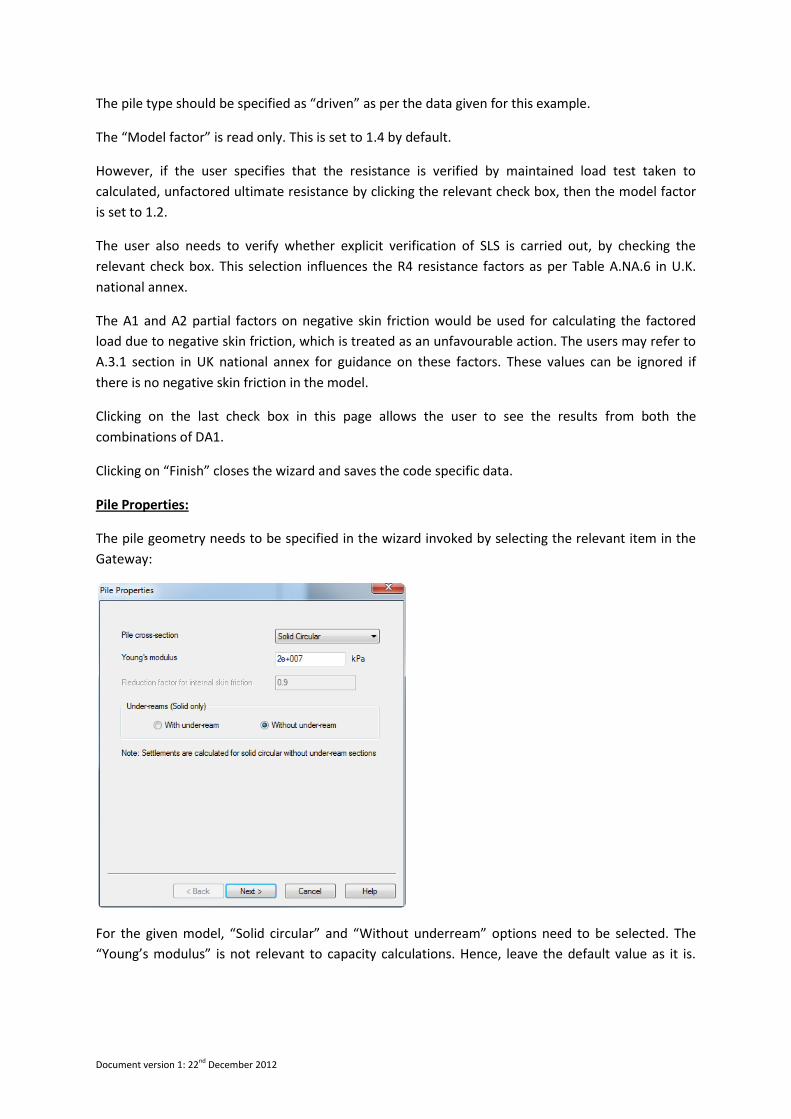
Pile Properties:
The pile geometry needs to be specified in the wizard invoked by selecting the relevant item in the
Gateway:
For the given model, “Solid circular” and “Without underream” options need to be selected. The
“Young’s modulus” is not relevant to capacity calculations. Hence, leave the default value as it is.
Document version 1: 22nd December 2012
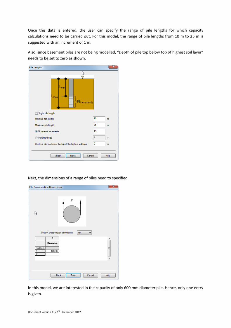
Once this data is entered, the user can specify the range of pile lengths for which capacity
calculations need to be carried out. For this model, the range of pile lengths from 10 m to 25 m is
suggested with an increment of 1 m.
Also, since basement piles are not being modelled, “Depth of pile top below top of highest soil layer”
needs to be set to zero as shown.
Next, the dimensions of a range of piles need to specified.
In this model, we are interested in the capacity of only 600 mm diameter pile. Hence, only one entry
is given.
Document version 1: 22nd December 2012
Clicking on “Finish” closes the wizard and saves the “Pile Properties” data.
Material Properties – Drained materials:
In this model, there is only one drained material - Sand. The following data for the same needs to be
entered in the “Undrained Materials” table by invoking the same from the Gateway.
As the material tables are wide, it is suggested to enter the data directly in the “General”, “Friction”
and “End Bearing” worksheets, instead of using the “All” worksheet.
Document version 1: 22nd December 2012
In the “Friction” and “Bearing” worksheets, the user needs to select the “qs –specified” and “qb-
specified” options, and enter the relevant values respectively as shown.
The fields M1 and M2 correspond to the material factor sets. In EC7 (U.K.) , all the M1 factors are
always 1.0. Hence the fields are not editable.
The field M2 may need to be explicitly entered by the user only in some circumstances. For example,
DA1 C2 uses M2 factors to calculate the unfavourable Geo actions – which translate to negative skin
friction for this program. However, the code only specifies M2 factors for
Angle of shearing resistance,
Effective cohesion,
Undrained shear strength, and
Unconfined strength.
The user need not explicitly enter the material factors if the skin friction and end-bearing values are
solely computed on the basis of the above 4 parameters. However, if the user directly specifies qs,
Nc, Nq or qb, then the program does not know the theory/formula which have been used in
computing the same. In these cases, the program uses the material factors specified by the user in
the tables above, to derive the “material factored” unfavourable geotechnical actions.
For this example, however, as there is no negative skin friction involved, these factors can be left at
the default value of 1.0.
Soil Profiles:
The user then has to define the soil profiles. Each soil profile is a collection of material layers.
The user can specify multiple soil profiles, particularly if he is using the “Model Pile” procedure”.
However, for EC7 (U.K.) national annex, the program only uses the “Alternative procedure”. Hence,
the user would be entering only one soil profile “S1” as shown:
Document version 1: 22nd December 2012
The user can enter multiple soil profiles for the “Alternative approach” also. In this case, the
program calculates design resistance of pile in each of these soil profiles independently.
Groundwater:
The user can specify the groundwater tables in the model in these worksheets.
In this particular example, there is only one soil profile and one ground water table. The same is
entered as shown.
If the user wants to model perched groundwater in a soil profile, he can use multiple data points to
model the pore-pressure in the soil profile. In this case, the pore pressure distribution will not be
hydrostatic.
Document version 1: 22nd December 2012
Soil –profile Groundwater Map:
This table is really used to associate a particular groundwater table to a particular soil profile.
IMPORTANT: By default, no groundwater table is associated to the soil profiles created by the user.
Hence, it is important to explicitly enter the data in this table when groundwater is present in a soil
profile.
Applied Loads & Displacements:
For the capacity part, the “Displacements” are not relevant.
The following load data needs to be entered as shown:
Document version 1: 22nd December 2012
Fields A1 and A2 refer to the action factor sets in EC7 (U.K.) N.A.
For this model example, it is assumed that for
Action factor set A1:
Dead load factor = 1.35
Live load factor = 1.50
Action factor set A2:
Dead load factor = 1.00
Live load factor = 1.30
Analysis & Results:
Once the data is input as shown above, the user can proceed for analysis by clicking the “Analyse”
button as shown:
This brings up the Pre-Analysis check dialog giving any warnings or errors in the model. If there are
no errors, the user can run the analysis by clicking the “Proceed” button.
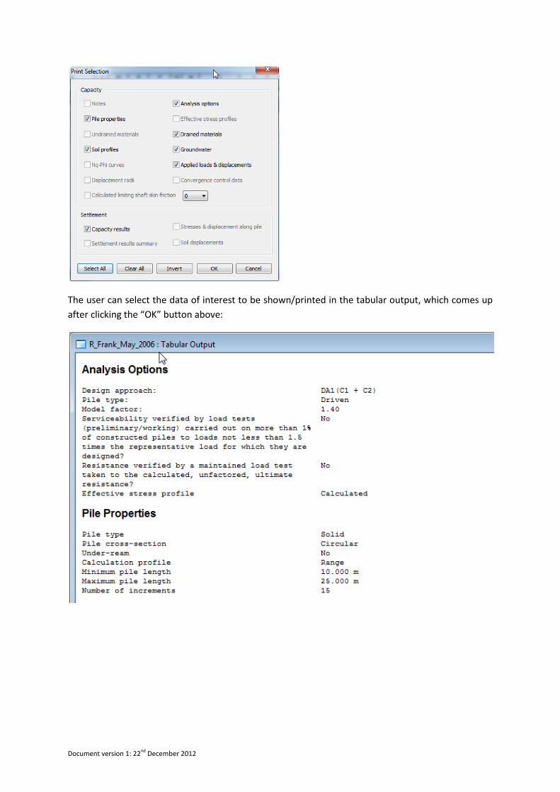
After completion of analysis, the following print selection dialog appears:
Document version 1: 22nd December 2012
The user can select the data of interest to be shown/printed in the tabular output, which comes up
after clicking the “OK” button above:
Document version 1: 22nd December 2012
The program prints the factored load and design resistance information at the pile lengths specified
by the user.
Validation:
A short validation is given below for the pile length of 25 m:
Unit end bearing stress = 1370 kPa
Area of the pile base = (PI/4)* (0.6)*(0.6) = 0.283 m2
Ultimate end bearing capacity = 1370*0.283 = 387.36 kN