72


State Environmental Conservation Department (ECD), Sabah, Malaysia
EIA Guideline for Construction on Hillslopes Final Draft
January 2001
Abbreviations DID Department of Irrigation and Drainage
DOE Department of Environment (Malaysia)
ECD Environmental Conservation Department (State of Sabah)
EIA Environmental Impact Assessment
ha hectare
km kilometre
m metre
m3 cubic metre
mg/L milligram per litre
RM Malaysian Ringgit
TSS Total Suspended Solids
Technical Report no. 8
Issue no. 6
Date of issue February 2001
Prepared Lim Peng Siong, Vitalis Moduying, Yabi Yangkat, Tony Greer,
Carsten Hollænder Laugesen, Eric Juin


Title
EIA Guideline for Construction on Hillslopes, Sabah, Malaysia
Published by
The Environmental Conservation Department, Sabah, Malaysia
Photos
Lim Peng Siong, F. Tating, Virinder Bablu Singh, Uwe Schmacke
Printed by
Syarikat Bumi Yakin, Sabah
Edition
First edition, 500 copies
Publication contact
The Environmental Conservation Department
2th & 3th floor, Wisma Budaya
Jalan Tunku Abdul Rahman
88999 Kota Kinabalu
Sabah, Malaysia
Phone: 088 251 290
Fax: 088 238 120
E-mail: [email protected]
Homepage: www.sabah.gov.my/jkas
All rights reserved
The publication can be quoted if reference is given

1
Table of Contents
1 Sabah Context 6 1.1 Geographical Overview 6
1.2 Geology in Relation to Instability/Landslides 10 1.3 Legal Requirements 11
1.4 Application and Approving Procedures 12 1.6 Typical Project Activities 14 1.7 Key Stakeholders 14
2 Environmental Impacts 18
2.1 Impacts Assessment based on site characteristics 18 2.3 Major Environmental Impacts 24
2.4 Additional Impacts 32
3. Mitigation Measures 38 3.1 Key Mitigation Measures 39 3.2 Slope Erosion Control Measures 39
3.3 Slope Stability Measures 41 3.4 Landscape 43
3.5 Additional Mitigation Measures 44 3.6 Secondary Rehabilitation Measures 45
4. Monitoring 48 4.1 Compliance monitoring 48
4.2 Impact Monitoring 49
Annexes

2
Preface
Hills with slopes having gradient of 20 degrees or more are prone to excessive topographical
changes, landslides and slope failures. Development on hillslope increases the prospect of
slope failure, or landslides, the problem becoming critical during the wet season. Indiscriminate
or uncontrolled construction on hillslopes could thus bring about dire consequences, including
severe damage to property and can also lead to loss of life.
Construction activities on hillslopes in Sabah, particularly in the urban centres and tourist resort
areas, have been on the increase in the last few years, sometimes with detrimental results.
These include the destruction of landscape, increased soil erosion, slope failures and loss of
lives.
In Sabah, the Environmental Conservation Department is, effective September 1999, charged
with regulating the construction on hills with slopes having gradient of 20 degrees or more to
ensure that development on hillslopes are conducted in an environmentally responsible man-
ner.
This guideline is produced to provide guidance on the scope of environmental considerations
required during the planning, pre-construction, construction and operations and maintenance
stage of construction on hillslope activities.
Through use of this document it is intended that the key environmental considerations will be
identified in the planning of construction on hillslope activities. Early identification of potential
environmental considerations will ensure that subsequent developments will be carried out with
minimal adverse environmental impacts.
ECD would like to express their appreciation to the Danish Co-operation for Environment and
Development (DANCED) for overseeing and assistance in preparation of these Guidelines
through ECD’s Capacity Building Project. Appreciation is also extended to all government
agencies, organisations and individuals for their contribution and support in formulation of this
Guideline.
Eric Juin
Director
Environmental Conservation Department

3
Introduction
The aim of this Guideline is to provide a framework for the preparation of EIA for construction
on hillslope activities under the requirements specified in the Sabah’s Conservation of Env i-
ronment Enactment 1996 and Conservation of Environment (Prescribed Activities) Order
1999. The Guideline is therefore intended for use by project proponents, environmental con-
sultants and approving authorities when initiating, assessing and approving the EIA for con-
struction on hillslope activities in the State of Sabah. The Guideline can, however, also be used
as a guideline for the development and control of other hillslope developments not covered by
the EIA regulations.
The Guideline should be regarded as complementary to the Handbook for Env ironmental Im-
pact Assessment (EIA) in Sabah, published by the Environmental Conservation Department.
The Guideline provides an easy to follow and practical means for assessing environmental
impacts, recommending mitigation measures and proposing monitoring programmes for:
• Construction of buildings for commercial purposes
• Construction of buildings exceeding 4 storeys high for residential purposes
• Construction of parks
• Construction of resorts
• Construction of other recreational facilities.
Construction on hills with slopes having gradient of 20 degrees or more is defined as the erec-
tion or assembly of structures (such as buildings), recreational facilities (such as parks and
resorts), and related access roads on hills with natural slopes having gradient of 20 degrees or
more. Throughout this Guideline, construction on hillslope is used as an abbreviated form to
cover all of the above activities. The method of determining whether the natural slope have
gradient of 20 degrees or more is stated in Annex A.
Specifically excluded from this Guideline is construction of major roads on hills with slopes
having gradient of 20 degrees or more; this activity will be covered by other guidelines.
This Guideline should be used in conjunction with the following documents:
• Handbook for Environmental Impact Assessment (EIA) in Sabah, published by the Envi-
ronmental Conservation Department, Sabah (ECD)
• Environmental Impact Assessment Guidelines for Development of Resort and Hotel Fa-
cilities in Hill Stations – EG8/95 published by the Department of Environment Malaysia
(DOE).

4
Newspaper clippings

5
Photo 0.1 Residential buildings on slopes of Signal Hill, Kota Kinabalu Photo 0.2 Resort on hillslope at
Kundasang
Photo 0.3-0.4 Condominiums/apartments on crest and slopes of Likas Ridge
Photo 0.5 Observation Tower at Signal Hill Kota Kinabalu Photo 0.6 Chinese Temple sited at top of Sand-
stone cliff, Sandakan Photo 0.7 Transmission Towers at crest of ridge
Photo 0.8 University campus built on hillslope

6
1 Sabah Context
1.1 Geographical Overview
The terrain of Sabah is generally hilly and mountainous. The western part of Sabah is domi-
nated by the northeast trending Crocker Range, which rises from near the west coast to 50 km
inland and stretches from the Sarawak border in the southwestern corner of the country to the
Kinabalu massif. The range rises up to about 1,200 to 1,800 m in height along a central spine.
The range culminates at its northern end in Mount Kinabalu (4,093 m). Between the Crocker
Range and the sea on the west coast is an extensive, heavily populated coastal plain with hills
reaching down to the sea in many places.
East of the Crocker Range are several less prominent ranges, also trending northeast. One of
these ranges is the Trusmadi Range; the second highest mountain, Mount Trusmadi (2,590
m), is located on this range. In the south central and part of east Sabah, the topography is
dominated by a series of circular to sub-circular basins ranging from 16 to 50 km across.
These basins are defined by curved ridges up to 1,800 m high and valleys.
A dissected plateau, the Lokan Peneplain, 65 km wide and 180 to 300 m high occurs between
Telupid and Sandakan. The southern part of the Sandakan Peninsula is hilly and terminates in
a number of spectacular escarpments facing Sandakan harbour. The Semporna Peninsula is
dominated by steep volcanic hills stretching parallel to the south coast. Inland from Tawau and
Lahad Datu (Segama-Kuamut areas), the terrain is mountainous, with hills of more than 900 m
high. The greater part of the east coast, including the Bengkoka, Sandakan and Dent Peninsu-
las, consist of low-lying plains and coastal swamps with occasional high ridges.
Five inter-montane plains are located along the west coast and interior; these are the Tenom,
Keningau, Tambunan, Patau and Ranau Plains. Each consists of terraces cut into alluvium
that was deposited in the steep-sided valleys of the mountain ranges.
Flat, non-swampy land available for development in Sabah is thus limited in extent compared to
the hilly terrain, which constitutes most of Sabah. As pressures from population growth, eco-
nomic activities and landuse activities grow, it is inevitable that parts of the hilly areas will be
developed.
Construction on hillslopes with gradients exceeding 20 degrees is becoming increasingly evi-
dent in urban centres around Sabah. This also includes hilly areas with tourism potential such
as Kundasang and Gunung Emas in Penampang. The types of structures erected on

7
such slopes range from residential houses to commercial condominiums/apartments and cha-
lets; other structures include temples, water storage reservoirs and telecommunica-
tion/transmission towers. In and near the urban areas of Kota Kinabalu and Sandakan, com-
mercial condominiums and apartments are the dominant type of structures erected on hill-
slopes while resorts and hotels are most common in areas with tourism potential.
In Sabah, the total area, which has been utilised for hillslope development, is estimated to be in
the region of 3 to 5 per cent. In Kota Kinabalu alone, hillslope development projects are esti-
mated to make up about 10 per cent of the developed area while in Sandakan the figure would
be less.
It is anticipated that construction on hillslope will increase in the near future as pressures from
population growth, economic activities and land in use pressure continue to increase. The con-
tinued growth in the tourism industry has prompted several proposed high-rise projects mainly
in the form of apartments for sale to the public and hotels for tourism purposes.
Construction on hills with slopes having a gradient of 20 degrees or more is normally carried
out for five purposes, namely:
• Personal requirements - individuals who own land on such slopes may want to construct
buildings for their own use
• Commercial requirements - land developers may construct condominiums and apart-
ments for sale to the public
• Tourism requirements - buildings such as hotels, resorts, parks and recreational facilities
may be constructed by both the public and private sector for tourism or recreational pur-
poses
• Religious purposes - religious bodies may want to erect places of worship
• Public Utilities - construction of major water storage/distribution reservoir and telecom-
munication/ transmission towers.

8
Table 1.1 Examples of areas where construction on hillslopes already have taken place District Area
Kota Kinabalu • Likas Ridge - Condominium, Apartment and Bungalow
• Signal Hill - Condominium, Flats, Observation Tower, Bungalow
• Shangrila-La Height - Condominium, Bungalow, Water Storage Res-
ervoir
• Inanam Laut - University Sandakan • Taman Merah - Bungalow
• Observation Platform
• Chinese Temple Ranau • Kundasang Perkasa Hotel
• Kinabalu Pines Resort
• Zen Garden Resort
• U-Merlin Resort Penampang • Gunung Emas - Resort
• Beverly Hills - Housing Tambunan • Gunung Alap - Resort Tenom • Tenom Town - Perkasa Hotel Tuaran • Tengihilan - Buddhist Retreat Centre

9
Figure 1.1. Overview of key areas with existing construction on hillslopes in Sabah

10
1.2 Geology in Relation to Instability/Landslides
The geology of Sabah is dominated by sedimentary formations. About 70 per cent of this
underlying geology is made of sedimentary rocks with about 10 per cent of rock types being
Terrace and Recent deposits. The remainder of the geology is intrusive and extrusive igneous
and metamorphic rocks.
The sedimentary formations comprise of a variety of rocks including interbedded sandstone
and mudstone, shale, siltstone, limestone, calcareous sandstone, chert, tuffite and slump
breccia. They are in varying degrees of consolidation. The sedimentary rocks which form the
mountain and hill ranges along the west coast of Sabah belong to the Crocker and Trusmadi
Formations; the rocks are strongly folded, faulted and fractured. The sedimentary rocks com-
posing the east coast of Sabah are poorly consolidated, gently folded and tilted. Some of the
formations consist predominantly of mudstone.
Terrace deposits are found in the Pinosuk Plateau, the Keningau-Sook Plain and along the
coastal areas. These consist of gravel, sand, silt and mud. The Pinosuk deposits are of glacial
origin, poorly sorted and consolidated and consist of blocks as much as a few metres across.
Intrusive igneous rocks form mountains and hills in the Kinabalu and Segama areas, including
the Mount Kinabalu. Volcanic rocks are mainly found in the Semporna Peninsula where they
form mountainous country along the spine of the Peninsula; associated with these volcanic
rocks are some intrusive rocks.
Weathering of the sedimentary formations is frequently severe, often reaching a depth of 30 m.
A completely weathered zone of 1 to 10 m thick has developed in most formations. The erodi-
bility of soils developed from the weathering of these sedimentary formations depends on soil
texture, aggregate stability, shear strength, infiltration capacity and organic and chemical con-
tent. Soils with high silt content are highly erodible.
Instability and landslides are recurrent problems associated with hillslope development affect-
ing excavation for building sites and road cuts (Table 1.2), particularly on the hilly terrain under-
lain by sedimentary rocks along the west coast, Kundasang and Sandakan areas. Landslides
are also common in steep terrain underlain by igneous intrusive rocks, particularly the ultra-
basic rocks, in the Lahad Datu and Telupid areas. The landslides may occur both in bedrock
and in overburden. Slides may also occur in fill material.
Bedrock slides are most common where planes of structural weakness such as bedding or
major joint planes dip towards the cut. Overburden slides occur mainly on semi-hemispherical
slip surface.

11
Table 1.2 Major landslides in Sabah
Date Locality Loss of
life/injury
Property Remarks
Feb. 8.,
1999
Kg. Gelam, 2 km
from Sandakan
17 dead, 2
injured
4 houses
destroyed
-
Jan. 6,
1999
Kg. Garib, Inanam 1 dead 1 house
damaged
-
Feb. 16,
1996
Kg. Pinosuk,
Ranau
- 4 houses
damaged
Many landslides along
Ranau-Telupid and Ranau-
Tamparuli Roads during the
same period
Aug. 28,
1995
KM. 25 Tambunan-
Penampang Road
1 dead 1 lorry
damaged
Disruption of water supply in
the Penampang area
Dec. 7,
1980
Tenom-Pangi Hy-
droelectric Power
Project area
3 buried,
several
injured
- -
Dec. 8,
1980
Kg. Kimanis, Pa-
par
3 dead 1 house
damaged
House slipped 50 feet down
the slope with the slide
Oct. 10,
1979
Bayview Heights,
Mile 3, Tuaran
Road
- 4 houses
damaged
Slide on fill material
Note: All affected houses were located on hillslopes and landslides occurred after periods of continuous
rain.
1.3 Legal Requirements
Effective September 1999, Environmental Impact Assessment (EIA) is a mandatory require-
ment for construction on hills with slopes having gradients of 20 degrees or more in Sabah
under the Conservation of Environment Enactment 1996 and the Conservation of Environment
(Prescribed Activities) Order 1999. Construction on hillslope is a Prescribed Activity, which
requires an EIA approval prior to project commencement. The development falls under two
categories:
Section 3: Development of Commercial, Industrial and Housing Estates. Paragraph (vi):
construction of buildings for commercial purposes or buildings exceeding 4 storeys high
for residential purposes on hills with slopes having gradient of 20 degrees or more; and
Section 7: Any other activities, which may damage or have an adverse impact on quality
of environment or natural resources of the State. Paragraph (i): construction of parks, re-
sorts or other recreational facilities or major roads on hills with slopes having gradient of
20 degrees or more.
Failure to observe this directive, the authority, body or person in default shall be guilty of an
offence and shall, on conviction, be liable to a term of imprisonment for 5 (five) years and a fine
of RM 50,000.00 (Malaysian Ringgit fifty thousand only).
12
1.4 Application and Approving Procedures
Effective September 1999, construction on hills with slopes having a gradient of 20 degrees or
more in the State of Sabah is subjected to an EIA requirement. This is in addition to the ap-
proval of the development plan by the relevant City/Municipal/Local District Council and rezon-
ing (change of land use) of the land by the Central Town and Country Planning Board.
Any person who intends to undertake construction on hills with slopes having a gradient of 20
degrees or more in the State of Sabah shall submit to the Director of the Environmental Con-
servation Department (ECD) an EIA Report. A copy of the development plan proposal should
also be submitted to ECD. The Department contact is:
The Director
Environmental Conservation Department
Tingkat 2 & 3, Wisma Budaya
88000 Kota Kinabalu, Sabah
Attention: Environmental Assessment Section
Tel: 088-251290/1
Fax: 088-238120
E-mail: [email protected]
Homepage: www. sabah. gov.my/jkas
Approval of the development plan is required from:
• The relevant City/Municipal/Local District Council for written approval of the Development
Plan.
Where the development involves a change in the land use, approval is required from:
• The Central Town and Country Planning Board for approval to rezone (change of lan-
duse) the land on which the construction will be carried out under Part I, Section 3 of
Town and Country Planning Ordinance 1950.
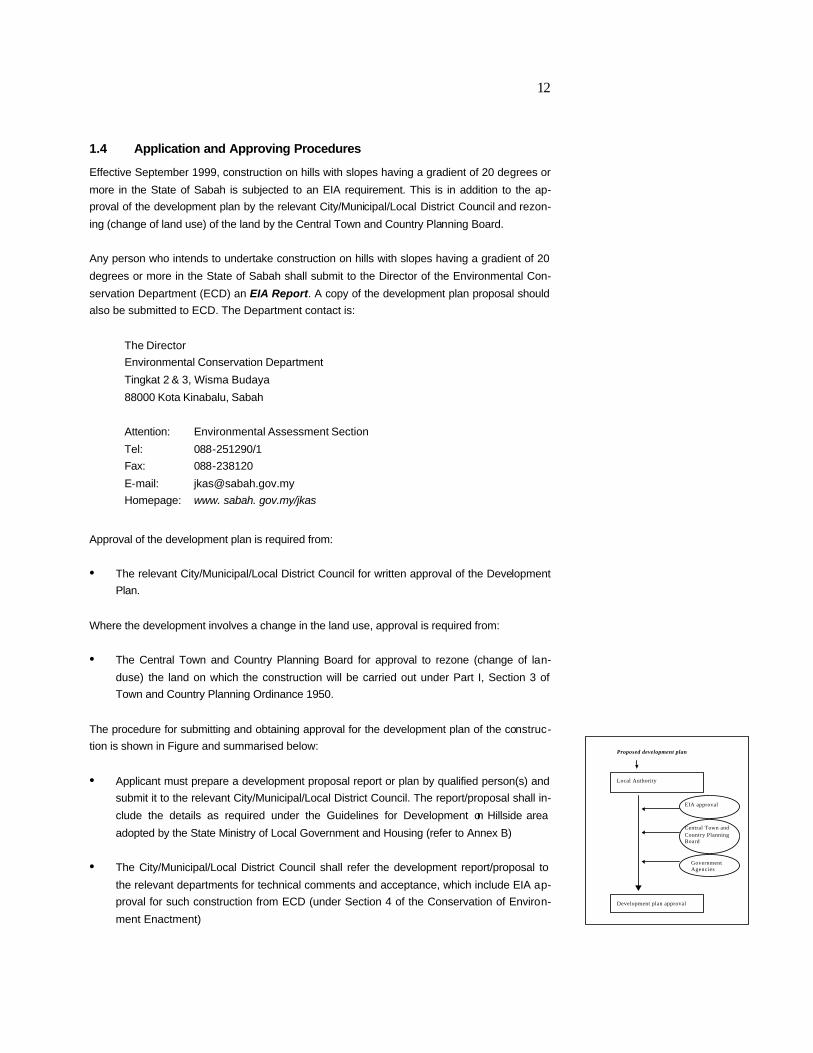
The procedure for submitting and obtaining approval for the development plan of the construc-
tion is shown in Figure and summarised below:
• Applicant must prepare a development proposal report or plan by qualified person(s) and
submit it to the relevant City/Municipal/Local District Council. The report/proposal shall in-
clude the details as required under the Guidelines for Development on Hillside area
adopted by the State Ministry of Local Government and Housing (refer to Annex B)
• The City/Municipal/Local District Council shall refer the development report/proposal to
the relevant departments for technical comments and acceptance, which include EIA ap-
proval for such construction from ECD (under Section 4 of the Conservation of Environ-
ment Enactment)
Local Authority
Development plan approval
Proposed development plan
EIA approval
Central Town and Country Planning Board
Government Agencies

13
• If the land has to be rezoned for different land use other than specified in land title, the
City/Municipal/Local District Council shall submit the application to the Central Town and
Country Planning Board for approval to rezone the site
• The City/Municipal/Local District Council may approve the application upon receiving ap-
proval from the Central Town and Country Planning Board for rezoning, approval of the
EIA report from ECD and technical comments and acceptance from the relevant depart-
ments on the proposal.
The project proponent has to be aware of the requirements of a development plan proposal to
avoid unnecessary delays in the application procedures. The development plan proposal report
must contain all the required details as listed in Annex B.
The list of required details implies that the site on a hillslope should be carefully selected during
the feasibility stage to ensure that the proposed site is environmentally acceptable. The proper
selection of site avoids problems that are often obvious and which may have adverse impacts
on the project. A proper site selection, when thoroughly undertaken, will eliminate obstacles to
the project that may affect its viability as a result of impacts to the environment that may be
costly to mitigate or control besides the other factors of acceptability for economic or technical
reasons. The characteristics of the site should influence the development plan.
Consideration on the selection of a location on the hillslope for construction depends primarily
on the availability of land and the physical characteristics of the site. The specific requirements,
as specified in the guidelines from the Ministry of Local Government and Housing, for proper
site selection are:
a) Low risk of slope failure at site and its surrounding
• Absence of fault zones
• Absence of slip zones, slope failures
• Geologically sound bedrock
• Bedrock or soil with good geotechnical properties
• Absence of historical earthquake activity
b) Does not have a conservation value
• No geological value such as fossils or geological structures which have been identified by
higher education institutions or the Department of Mineral and Geoscience as a site suit-
able for gazettement as a study area
• No unique geomorphic features such as limestone peaks
• Absence of protected plant or animal species
• Not within forested ridge areas which have inherent visual qualities
c) Not gazetted as permanent forest reserve, water catchment, or zoned as an area having
mineral resource, ridge conservation area
d) Absence of unique or characteristic features, which are important identities, attached to an
area and which may not be disturbed.

14
1.6 Typical Project Activities
A typical hillslope construction operation involves activities, which can be grouped into three
phases as follows:
• Pre-construction – Activities carried out during this phase include site access and track
development, site surveying, geological/geotechnical investigation, including a study of the
stability of the site and surrounding area
• Site preparation and construction - Activities at this phase include access road develop-
ment, base camp construction, site clearing, earthworks, drainage works, development of
utilities, construction of buildings and facilities, transportation of construction materials,
equipment and machinery operation, waste disposal and abandonment
• Operations and Maintenance – Wastewater treatment, solid waste management, traffic
management, labour force management, conservation works, general maintenance
works and visitor management are the main activities in this phase.
A summary of a typical construction activity is shown in Table 1.3.
1.7 Key Stakeholders
Key stakeholders in construction on hillslopes activities in Sabah include:
• City/Municipal/Local Councils to issue written approval for the development plan
• Environmental Conservation Department (ECD) to approve EIA to carry out construction
on hillslopes within the State
• Central Town and Country Planning Board to approve application for rezoning Govern-
ment Agencies to give technical comment in relation to the development plan
• Housing Developers Association - the association for housing developers
• Land owners to construct buildings of more than 4 storeys for their own use
• Corporations construct buildings for their own use or for commercial purposes
• Public agencies construct public facilities and other governmental structures
• Private land developers construct apartments, condominiums, housing, resorts, hotels,
chalets either as a company or as an individual
A list of experts and other relevant contacts is given in Annex C.

15
Table 1.3 Construction Activities
Phase Locality Activity
Pre-Construction Construction Site • Site surveying
• Geological/geotechnical investigation, including
stability of site and surrounding area
Access • Site access track development
Site Preparation
and Construction
Construction Site • Development of access road
• Setting up of base camps
• Site clearing
• Earthworks
• Drainage works
• Development of utilities
• Construction of buildings and facilities
• Transportation of construction materials
• Equipment and machinery operation
• Waste disposal
• Abandonment of site
Access Road • Upgrading of access track
Operations and
Maintenance
Construction Site • Wastewater treatment
• Solid waste management
• Traffic management
• Conservation works
• General maintenance works
• Visitor management
Access Road • Maintenance of road and slopes
Photo 1.1 Clearing of project site Photo 1.2 Laying of pad footing Photo 1.3 Micropiling

16

17
•
18
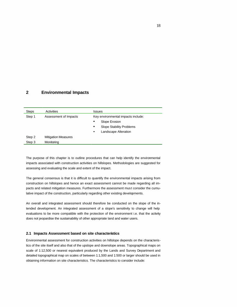
2 Environmental Impacts
Steps Activities Issues
Step 1 Assessment of Impacts Key environmental impacts include:
• Slope Erosion
• Slope Stability Problems
• Landscape Alteration Step 2 Mitigation Measures
Step 3 Monitoring
The purpose of this chapter is to outline procedures that can help identify the environmental
impacts associated with construction activities on hillslopes. Methodologies are suggested for
assessing and evaluating the scale and extent of the impact.
The general consensus is that it is difficult to quantify the environmental impacts arising from
construction on hillslopes and hence an exact assessment cannot be made regarding all im-
pacts and related mitigation measures. Furthermore the assessment mus t consider the cumu-
lative impact of the construction, particularly regarding other existing developments.
An overall and integrated assessment should therefore be conducted on the slope of the in-
tended development. An integrated assessment of a slope's sensitivity to change will help
evaluations to be more compatible with the protection of the environment i.e. that the activity
does not jeopardise the sustainability of other appropriate land and water users.
2.1 Impacts Assessment based on site characteristics
Environmental assessment for construction activities on hillslope depends on the characteris-
tics of the site itself and also that of the upslope and downslope areas. Topographical maps on
scale of 1:12,500 or nearest equivalent produced by the Lands and Survey Department and
detailed topographical map on scales of between 1:1,500 and 1:500 or larger should be used in
obtaining information on site characteristics. The characteristics to consider include:

19
• Location of site in relation to overall slope system
• The geology
• Soil type and depth
• Drainage system
• Vegetation cover.
2.1.1 Slope Development and Forms
Slope forms and slope processes are important considerations in landuse planning, both from
the viewpoint of the environmental constraints they pose and the environmental impacts related
to subsequent slope alteration.
The physical landscape is no more than an assemblage of valley- and hillside slopes and the
dimensions and appearance of slopes give an area its essential morphological character. Vari-
ous theories have been forwarded to explain the development of slopes.
The slope evolution approach is concerned with tracing the historical development of the slope
from its initiation to its present-day form. Under this approach, slopes tend to decline in steep-
ness as the cycle of erosion proceeds towards the stage of old age. Thus steep slopes are
designated as ‘youthful’ and gentle ones as ‘old’. However, it has been observed that the rate of
slope development varies from area to area and from one type of rock to another. Modern-day
geomorphologists, however, contend that time may not be an important factor in slope modifi-
cation, but that the slope form is merely ‘adjusted’ in response to changes in controlling factors.
There is therefore a direct casual relationship between the processes of weathering, transpor-
tation, erosion and deposition and the form and gradient of slopes. The immense variety of
slope form and steepness is due to the fact that processes of erosion operates in varying
combinations and with differing relative effectiveness in areas of different rock type, structure,
climate, vegetation, relief and so on. The form of any slope is therefore affected by a number of
factors, including
• Chemical composition of the rock
• Jointing
• Permeability
• Angle of dip
• Rate of erosion of the river at the foot of the slope
• Climate
• Nature and rate of weathering
• Nature and rate of transportational processes such as creep and wash
• Nature of the vegetation cover and contemporary earth movements.

20
The main types of slope forms recognisable are cliffs, concave slope, rectilinear slopes and
convex slopes (see Figure 2.1).
Cliffs are developed on slopes in deeply cut river valleys, on escarpment faces (long steep
slopes at the edge of a plateau) in massive rocks and on faulted landscapes. Cliffs are steep,
with faces often 40 degrees or more and the products of weathering for the most part fall im-
mediately to the base. A talus or scree slope (depositional feature) will develop at an angle con-
trolled by the size and shape of the weathered fragments (see Figure 2.1.A).
The lower part of a slope profile will commonly exhibit a concave section (see Figure 2.1.C)
due, in some cases, to deposition processes. However, it is more usual to find slopes covered
only by a thin layer of soil or exposing bare rocks with marked basal concavities. Many slopes
display rectilinear sections (see Figure 2.1.E), which normally form the steepest part of the
whole profile. It is quite common to find such a major rectilinear section leading down to the
very bottom of the valley. On other slopes, the rectilinear section is restricted to the central part
of the profile where it separates a broader convexity above from a large concave section below.
Convex sections (see Figure 2.1.D) are common to many slopes and usually develop on the
upper part of the slope (summital convexity) due to erosional processes and are rarely covered
by more than a thin layer of soil.
Most slopes, however, are not made up of these simple forms but rather are compos ite result-
ing from a combination in one profile of two or more of these simple forms. A convexo-
rectilinear-concave slope comprises an upper convexity, a central rectilinear section and a
lower concavity, the three grading into each other to give a smoothly curving profile, (see Figure
2.2.A). Such slopes typically form on weak rocks. In areas where the rock type is varied, com-
prising alternating resistant and less resistant strata there may be a whole sequence of con-
vexities, rectilinearities and concavities, giving a ‘complex slope form’.
In an area of (i) alternating massive and thinly bedded weak strata, (ii) where the relief/lack of
tension is considerable, (iii) valleys are deeply incised/cut and (iv) where active weathering is
taking place, the slope profile may comprise of numerous free faces (associated with massive
strata) and rectilinear debris-controlled slopes (in the more easily weathered thinly bedded
rocks) and summital convexities and basal concavities may be very limited in extent or absent
altogether (see Figure 2.2.B).
In areas of hard crystalline rock, a composite slope form may be developed with an upper free
face (at an angle of 40 degrees or more), a central boulder-controlled slope at over 25 degrees)
and a lower concave slope, the pediment at less than 7 degrees (see Figure 2.1.B and 2.2.C).
In the assessment of impacts of construction activities on hillslope, representative cross-
section profiles of the whole slope should be drawn (such profiles should be drawn during the
development planning stage) to determine the form of the slope. This will aid in assessing the
area of influence of the project on the downslope section of the slope and also the area of influ-
ence of upslope activities on the project site itself.

21
Figure 2.1 Simple Slope Forms (after Small, 1983)
Figure 2.2. Complex Slope Forms (after Small, 1983)

22
2.1.2 Geology
Geology and rock types exert an important influence on the types of soils found in an area, the
shape of the slope and the stability of the site. Rock structures (bedding planes, folds, joints,
faults) are an important factor in the stability of natural hillslopes. For example:
• Steep terrain often has highly fractured rocks exposed, which increase the susceptibility
of the area to rockslides and landslides
• Weak rock types are frequently combined with unfavourable geologic structures and ac-
tive tectonism (changes in the earths crust), creating regions where large portions of the
hillslopes are formed by mass movement processes.
2.1.3 Soil Type
Soils are developed from the weathering of rocks. Different rock types produce different soil
types with different chemical and mechanical properties. Erodibility is defined as the resistance
of the soil to both detachment and transport and varies with soil texture, aggregate stability,
shear strength, infiltration capacity and organic and chemical content. The erodibility of soil is
one of the factors controlling erosion. Shallow soils normally occur in hillslopes and are very
often non-cohesive and tend to be subjected to erosion very easily.
2.1.4 Drainage System
Eroded material will be transported downstream by streams and into rivers polluting them. It is
thus important to characterise the hydrological condition at the site, both surface and under-
ground. Surface and underground hydrological characteristics of importance include:
• Drainage pattern
• Dimensions and flows of stream and rivers
• Springs and wells, including flow
• Natural drainage depressions, basins and sinks
• Floodplains, both on site and downstream that will undergo change due to grading and
construction
• Subsurface conditions including depth to water table, flow pattern of groundwater and
aquifer type.
2.1.5 Vegetation
The role of vegetation in reducing erosion has been well documented. Vegetation cover helps
to break the impact of falling rain drops and hence reduces the erosive force of the raindrops.
The roots of trees also play an important role in reducing erosion and site stability by binding
soil mantles to subsoils or substrata thus contributing to the mechanical strength of the soil.
2.1.5 Mapping
Maps used for the description of site characteristic include for example topographical, slope,
geological, land use and geomorphological maps. Examples are shown in Figure 2.3-2.7.

23

24
2.3 Major Environmental Impacts
The major adverse environmental impacts of construction on hillslope activity are:
• Slope erosion and siltation due to (i) removal of vegetation creating bared surfaces and
(ii) cutting of the hillslope creating steeper slope and increasing surface runoff
• Slope stability problems due to (i) removal of footslope, (ii) changes in stress conditions
of rock underlying slope, (iii) change in groundwater conditions and (iv) increasing load on
slope section where structure will be sited
• Landscape impacts due to (i) the direct physical change to existing physical features
such as removal of vegetation, alteration of topography and erection of buildings and
structures.
Other adverse environmental impacts of construction on hillslope activity include:
• Loss of ecological habitat
• Objectionable noise levels from construction and transportation activities
• Dust and atmospheric pollutants from machinery and transport vehicles
• Vibration associated with piling, vehicular movement and blasting
• Traffic and transportation
• Wastewater and solid waste disposal.
The above assessment of what constitutes major and minor impacts is based on a holistic and
integrated approach. The criteria used are shown in Annex D.
2.3.1 Slope Erosion
Erosion on slopes takes place when one or more of the following conditions exist: (i) The slope
length is long, (ii) the slope is steep, (iii) The soil is highly erodible and/or the soil cover (vegeta-
tion) has been removed and will take some time to be re-established.
Construction on hills with slopes having a gradient of 20 degrees (steep slope) invariably in-
volves removal of vegetation, the creation of cuts and fills and can therefore accelerate the
process of soil erosion on slopes.
Clearing of the site involves earthworks in the preparation of the siting of structures. This will
inevitably result in the removal of vegetation and the creation of cleared surfaces, which then
become vulnerable to the erosive effect of rain. When a raindrop falls, it is usually absorbed
into the pore spaces of the soil. However, when these pore spaces are saturated, the raindrops
will either stand on the surface as a puddle or more likely flow downhill. As the water flows
downhill, it will carry with it bits of debris and soil particles. The greater the rainfall intensity the
greater the available run off to remove material. Erosion on exposed slopes starts with
rainsplash leading to sheet, rill and gully erosion and the creation of badland if the site is aban-
doned. Soil loss due to erosion will subsequently be discharged into streams. Not all eroded
material is discharged immediately and much of it is deposited temporarily on the land surface
where slopes become gentler (see Figure 2.3 and photos).

25
Cuts and fills change the slope angle, often creating steeper slopes. The steeper the slope the
faster the runoff flows and the more force it will have to move material downslope.
Photo 2.1 Sheet erosion Photo 2.2 Rill erosion on artificial slope Photo 2.3 Gully erosion
Figure 2.8 Erosion and resultant geomorphic features (after Marsh 1969)
Assessment Method for Slope Erosion
It is important to assess and identify high erosion risk areas where soil erosion risk will in-
crease during the construction period and the anticipated erosion risk after completion of pro-
ject. Erosion risk from construction of access road should also be considered. The methodol-
ogy for the assessment of soil erosion risk can involve the following steps:
1. Examine available maps, which includes for example topographical, land use and vegeta-
tion cover maps, all including the surroundings (to the first sharp break in slope above and be-
low the site or at least a minimum 500 m upslope and downslope of the site whichever is appli-
cable). Maps on a scale of 1:12,500 or nearest equivalent produced by the Lands and Survey
Department would serve and such maps exist for most parts of S abah. The following features
should be identified:
• Drainage lines (permanent, intermittent and dry valleys)
• Erosion features such as rills, gullies, badlands, mass movement, bank erosion etc.)
• Areas of sedimentation, including streams
• Man-made features such as settlement, tracks, roads etc.
• Water users and intake points downstream
• Type of vegetation cover
• Soil type and depth.
2. Examine aerial photographs, when available, of the proposed site and surroundings in-
cluding alignment of access road, and again if available, examine photographs of different
dates as they record changes in land use over time. Aerial photographs of scale 1:5,000 or 1:

26
12,500 should be used. Plot detail of erosion features such as rills, gullies alongside related
factors such as land use and vegetation cover. The information obtained should be transferred
to the base map of scale 1:12,500 or nearest equivalent.
3. Carry out field surveys to verify the features identified in (1) and (2) and to add additional
information such as other erosion sources, discharges, nature of river/stream water down-
stream (clean or already sedimented) and water users downstream/slope (e.g. water intake,
mangrove swamp, etc.).
4. Prepare a pre-erosion risk map. This map should include relevant data gathered in step
(1)-(3) and provide information on for example (i) location of existing areas with high erosion
rates within the site and along alignment of access road with high erosion rates, (ii) amount
(including percentage of total land) of areas with high erosion rates and (iii) exis ting areas of
sedimentation, including existing drainage. This map will assist in assessing the location, na-
ture and magnitude of change in erosion risk due to construction and development.
5. Make a post-erosion risk assessment, including a post-erosion risk map. Erosion risks
are higher during the construction stage when the land is cleared and exposed for a period of
time. The longer the exposure period, the more serious the soil loss. The seriousness of soil
erosion during the construction stage will depend on the size and location of land cleared and
the period and phasing of exposure. These factors should be studied and described through an
overall post-erosion risk/hazard assessment.
This assessment should include the preparation of a post-erosion risk map, which is overlaid
the pre-erosion risk map. The post-erosion risk map shall show the soil erosion risks during
construction stage, taking size, location, phasing and period of exposure into consideration.
The post-erosion risk map should include the site and the surrounding areas.
This soil loss assessment will assist in assessing the mitigating measures proposed in the
development plan to control soil erosion during construction stage.
As no exact quantifiable erosion criteria exist, a ‘best possible’ assessment of the significance
of the overall soil erosion risk alongside a careful assessment of the geomorphological condi-
tion of the slope should provide indication as to whether or not the project places the environ-
ment at risk. Criteria used for the environmental assessment should include for example:
• Period of exposure of cleared land and predicted soil loss during the exposed period
• State of water quality downstream of the proposed site
• Number of beneficial users sensitive to water pollution downstream
• Extent of sedimentation and damage to property downstream.
2.3.2 Slope Stability Problems
Landforms are the products of the local balance between weathering, erosion and deposition
and are continuously evolving. Slopes that are too steep for the weathered material to remain
stable are subject to periodic failure. Instability may be associated with moderate to steeply
sloping terrain or with land, which has been disturbed by man. Natural slopes that have been
stable for years may suddenly fail because of construction activities on hillslope, which may
bring about:

27
• Changes in the slope topography
• Changes in ground water conditions
• Loss of cohesive strength of soil
• Stress changes in the soil underlying the slope
• Acceleration of the rate of weathering of rock.
Accelerated weathering. Changes to the terrain and hydrology through construction, earthworks
or removal or vegetation cover may cause erosion which create conditions conducive to mass
movement if exposed surfaces are not protected within a short period. Exposed rocks will be
weathered at a faster rate and the weathered material is susceptible to movement especially
when saturated with water. Such conditions are commonly found in denuded and eroded ex-
posed slope surfaces of delayed or abandoned development projects in Sabah.
Cut-and-fill. Cut-and-fill platforms are usually created to site the structures. Slope cutting
changes the slope topography and releases residual horizontal stresses and cause expansion
of the slope. Joints or weak zones may be exposed along which sliding may occur. Overcutting
the toe or oversteepening of the slope gradient to create a platform can therefore induce insta-
bility. Placement of fill will also lead to increase in shear stresses acting on slopes and may
lead to slope failure. The fill may fail if it is not properly designed and constructed to stringent
requirements.
Hydrological change. Drainage patterns of an existing terrain may be altered as a result of
construction. The change in groundwater flow patterns may cause changes detrimental to the
stability of the newly constructed slopes of the existing in situ slopes that were stable prior to
construction.
Assessment Method for Slope Stability
The following dimensions are suggested as guideline for defining the area of influence upslope
and downslope of the project site. In general, the area of influence is to the first sharp break in
slope above and below the site or at least a minimum 500 m upslope and downslope of the site
whichever is applicable. It should be borne in mind, however, that topographic features might
indicate modifications to this general axiom. The area of influence will be finally agreed upon
between the ECD and the EIA consultant during the preparation of the TOR for the EIA study.
When dealing with slope stability assessment, previous geological and geotechnical experi-
ence in the area of interest is valuable especially if a particular type of slope failure has been
established for a previous failed slope in the same area.
The methodology for the site assessment of slope stability can involve the following steps:
1. Collating information from existing records/reports. Geotechnical and geological infor-
mation from records of development of area (site investigation, boring, piling, foundation, slope
stability studies) should be obtained and compiled from relevant government agencies (e.g.
JKR, Department of Mineral and Geoscience) and from consulting architects and engineers.
The data shall be assessed (expert opinion may be necessary) and potential slope instability
areas identified and transferred to map of appropriate scale; topographical maps on a scale of
1:12,500 or nearest equivalent covering most parts of Sabah would serve as a good base. Ex-
amining geomorphic and drainage patterns from the topographical maps also give an indication
of materials likely to be found at site

28
2. Studying aerial photographs, when available. The study of aerial photographs in the as-
sessment of slope erosion should incorporate the identification of geological and geomor-
phological features including features, which suggest instability. Aerial photographs of about 1:
25,000 are widely available while some areas are covered by larger scale aerial photographs.
When available, aerial photographs of different time intervals should be studied to build up a
history of development in the area. Data from aerial photograph interpretation should be trans-
ferred onto a map of 1:12,500 or nearest equivalent scale
3. Field survey assessment of the site characteristics. A field survey should be conducted
to verify the features interpreted from aerial photograhs and information from existing geological
and geotechnical reports of the site. The field survey of site characteristic should include the
location of site in relation to overall complexity of the slope system, the geology, soil type and
depth, drainage system and vegetation cover. It should also include geological and instability
features. Geological features of interest are joints, fault zones, type of fault and movement,
zones of weak rocks, seepages/springs and scarps. Efforts should be made to identify instabil-
ity features, including tilting of trees, poles, settlement, recent landslides, old landslides/slips,
rock falls/topples, direction of slide movement, heave and bulge. Information from local resi-
dents, in particular on past landslides, should also be noted and recorded.
Information on the subsurface condition (type and extent of rock/soil underlying site, relevant
properties such as permeability, strength, and groundwater regime) of the site can be obtained
from geotechnical investigation reports. These data should be correlated with the field survey
surface data.
4. Preparation of a slope sensitivity map. Data obtained from step (1)-(3) should be trans-
ferred and plotted onto a slope sensitivity map. This map should identify and clearly mark
stability features of the site and surroundings, including slope sensitive areas (unstable areas)
with potential instability problems. Sensitive areas should be avoided or if affected by the pro-
posed development, should be properly stabilised.
5. Analysing and mapping the run-out zone in the event of a landslide originating from
the site. The effects of landslides extend downslope, and there therefore is a need to estimate
the extent and nature of landslide runout based on available data in the event that the assess-
ment of site characteristics shows that there is a potential for a landslide to originate at the site.
The assessment should, at least result in a map identifying locations where delivery of slide
debris is most likely, where the slide is likely to initiate and the potential downslope/downstream
impacts on property and life. Similarly, if a potential slide zone has been identified upslope of
the site, the runout zone should be estimated and delineated on a map and the impact on the
proposed development assessed.
5. Assessing and mapping the type of development and the potential for increased fu-
ture instability. Given the proposed development and the anticipated changes in surface and
subsurface conditions at the site, an assessment of the increased potential for future slope
stability problems in the area should be made. The type of structures to be erected and the
specific locations of these structures as per the development proposal are critical in this as-
sessment. The assessment should map and evaluate the type of development and siting of
structures and whether or not this raises the risk of slope instability, particularly where these
structures are to be sited on or close to sensitive areas as identified earlier.

29
The assessment of slope stability may be based on an overall evaluation of slope stability con-
ditions of the site and its immediate surrounding. The assessment should consider the short-
and long-term stability of the site and that of the surrounding environment, possibility of land-
slides involving natural or engineered slopes, type and scale of development, surrounding lan-
duse and proposed mitigating measures. The use of 2nd opinion of the assessment might be
included.
Photo 2.5 Debris avalanche from a landslide on steep slope. Photo 2.11 Landslide affecting road built on
slope Photo 2.7 Active slide as suggested by the slanting of trees
Photo 2.8 Slope movement as indicated by tilted oil palm tree Photo 2.10 Sign of slope movement as
suggested by tension cracks Photo 2.9 Sliding of rocks along a bedding plane Photo 2.6 Bulging of toe of
a failed slope.
2.3.3 Landscape
Landscape is defined (Hill and Revell, 1989) as " the outdoor environment, natural or built,
which can be directly perceived by a person visiting and using that environment". The term
landscape focuses upon the visual properties or characteristics of the environment including
natural and man-made elements, and physical and biological resources, which could be identi-
fied visually. The impact on landscape is therefore a direct physical change to existing land-
scape features such as vegetation, topography, open space and recreational facilities as well
as buildings and structures. Visual impact is a change to the appearance of the landscape and
the subsequent effect on the views of groups of people at particularly sensitive viewpoints.
Visual impact can vary from overall improvement to degradation. For example; construction of
chalets on a hillslope could lead to improvement of the visual quality and enhance the attrac-
tiveness of the landscape, erection of a 5 storey hotel on a ridge top could lead to visual ob-
struction and blocking of views, a poorly designed 4 storey bungalow could be in visual incom-
30
patibility with the surroundings, because the design features are not appealing and reduces the
overall visual quality of the area.
Constructions on hillslope will unavoidable bring about a change in the landscape and will thus
have a visual impact on landscape quality.
Assessment Method for Landscape
Landscape and visual impact assessment shall be directed towards predicting and judging the
significance of the effects the new development may have on landscape character and visual
amenity. The perception and aspiration of the community on particular landscape features
must be taken into account. The assessment should also take into account the compatibility of
the proposed development with existing local plans and regional planning.
The methodology for the site assessment of landscape impacts can involve the following
steps:
1. Preparation of inventory. For an assessment of the landscape, an inventory of the existing
landscape and visual characteristics of the area is necessary. The purpose is to identify, clas-
sify and record the location and quality of visual resources and values. The inventory can be
prepared by examination of aerial photographs, desktop study and site inspection. A photo-
graphic record of the site shall be prepared. The inventory shall at least cover the following
aspects:
• Physical aspects such as geology, landform, drainage
• Human aspects such as cultural features, buildings and settlements, people affected and
their perception of the landscape character
• Aesthetic aspects such as the views available, visual amenity and visual character
• The extent of vegetation that will be destroyed as per the development plan proposal.
Maps, photographs and imageries of visual resources of the area will be produced. The inven-
tory of the landscape and visual resources of the area shall be appraised and shall focus pri-
marily on the quality, sensitivity of the landscape and its ability to accommodate change.
2. Preparation of a visual envelope. A visual envelope is the number and extent of visual
receivers. The establishment of the visual envelope should be based on desktop study as well
as site investigation. Visual receivers within the visual envelope should be chosen from a vari-
ety of distances and viewpoints. In assessing visual impacts, it is important to cover as many
viewpoints as possible. Key viewpoints to be selected includes viewpoints from major routes
e.g. roads, footpaths, and at activity nodes e.g. residential areas, important public open spaces
and landmarks. The number and extent of visual receivers should be described and mapped.
The exact location of selected viewpoints used should be given.
3. Visualisation. A visualisation of the proposed development shall be made. Visualisation
techniques such as perspective drawings, plans and section elevation diagrams, photomon-
tages and computer imaging can be used to demonstrate how the proposed project will look.
The choice of presentation technique for the perspective views will depend on the complexity of
the proposed project, number of viewpoints and visual sensitivity of the area. The exact location
of selected viewpoints used for visualisation should be given.

31
4. Review of planning and control issues. It is important to review the planning and devel-
opment control development framework (development plan, lease conditions, special design
areas, landmarks, monuments, guidelines and control on urban design, landscape-related zon-
ing etc.) as these will provide an insight into the future outlook of the area affected and the ways
the construction project can fit into the wider context.
5. Make an overall assessment of the landscape impact. The assessment of landscape
and visual may be based on the type and extent of the construction impact on the environment,
and could include assessment of for example:
• Level of change to the existing landscape condition, which includes direct impacts (relat-
ing to physical removal or destruction of features) upon specific landscape elements, as
well as more subtle effects upon overall pattern of landscape elements that give rise to
landscape character, and local and regional distinctiveness
• Scale of the proposed works in relation to the overall view
• Impacts upon acknowledged special interest or values such as areas of high landform
with special landscape significance
• Proximity of sensitive viewpoints to the proposed development
• Compliance with existing guidelines, planning and control issues.
Examples of special landscape features that may contribute to the landscape character of a
site, area or region include:
• Areas of distinctive landscape character, e.g. characteristic combinations of land cover-
age creating a sense of place
• Valued landscape, e.g. country parks, protected coastline, areas of high landscape value,
woodland, scenic spots
• Other conservation interest, e.g. protected areas, designated buffer zones, wetlands,
historic landscape, sites or buildings of cultural heritage
• Specific landscape elements, e.g. hilltops, ridgeline, coastline, river valleys and wood-
lands.
Photo 2.11 Condominiums and apartments rising from the slopes and top of Likas Ridge Photo 2.12 a + b
Slope of ridge stripped of vegetation and replaced by cut slopes and buildings

32
A checklist of assessment criteria such as shown in Table 2.1 can be used.
Table 2.1 Example of assessment criteria checklist
Item Compatibility with surroundings Yes No
1 Height
2 Shape
3 Proportion
4 Building elements, colours and materials used
Obstruction of views
5 Block views from existing key viewpoints towards existing landscape
features
6 Block views form existing/planned view corridors towards landmarks
and features
Landscape/visual quality enhancement
7 Appealing design features that enhance attractiveness of the land-
scape
8 Clears visual obstruction of notable landmarks/features from existing
key viewpoints
Visual interference
9 Uncomfortable eye feeling/glare caused by reflection of sunlight from
structures faced with mirror
10 Uncomfortable eye feeling/glare caused by direct light sources gener-
ated from proposed development
11 Reduces sightings of wildlife
2.4 Additional Impacts
2.4.1 Ecological Impact
Construction on hillslopes will change habitats thereby impairing flora and fauna. The main
ecological impacts are related to the clearing of vegetation and water pollution, and the main
objective of an ecological assessment is to provide sufficient ecological data to allow an identi-
fication, prediction and evaluation of the potential ecological impacts. A site inventory is vital in
order to determine what, where and in what numbers communities of fauna and flora occur at
or nearby the project site. This is particularly important where the site is within or adjacent to
sensitive environments such as mangroves, parks or other protected areas.
As required under the Guidelines for Construction in Hilly Areas (see Annex A), the project pro-
ponent has to incorporate into his development plan proposal a report on the vegetation found
at the site. These data should serve as an initial inventory of the flora and fauna found at the
site and should be reviewed and verified by carrying out site inspection.

33
A useful inventory for management purposes is a habitat map. This can be produced by site
surveys alone, using the location base map and by sketching in habitat types. . If it is known
that the site is either a permanent or temporary home for endangered species data should be
collected on these species, and the distribution and location of endangered or protected spe-
cies should be recorded. Surveys of aquatic environment need only be carried out if the site is
located upstream of aquatic sensitive areas.
The ecological impact should be assessed against the location of site clearing as indicated in
the development proposal plan, the possible water pollution, the size of sensitive areas in and
around the construction site that will be destroyed and the presence of sensitive aquatic areas
downstream.
2.4.2 Noise
The sources of noise in construction activity on hillslope are mainly construction noise gener-
ated by semi-mobile machinery, which includes excavators, loaders, bulldozers, piling machine
and cranes, and mobile machinery, which includes dump trucks, lorries and graders. The ma-
chinery and vehicles operates along the access roads and at the construction site. Most of the
noise from these sources is inherent and difficult to subdue.
Since the operation of most construction equipment and machinery will result in elevated noise
levels, a risk assessment of noise pollution on the population living in the area should be made.
The risk assessment should be based on the number of people exposed to high noise levels
and considered against the length of the construction period.
2.4.3 Dust
Dust is a cause of concern for residents living along and near the access roads and project
site during the site clearing and construction stage. Dust can be generated by earth-moving
lorries, grader along the access road under construction, movement of overburden, wind blow-
ing upon the cleared site. In addition, vehicles and earth moving equipment will emit exhaust
and fumes.
A risk assessment of dust pollution on the population living in the area should be made. The
risk will be dependent on the number of people exposed to elevated dust levels and the period
of exposure. The risk should therefore be assessed based on the number of people exposed to
high dust levels, length of construction and length of dry periods.
2.4.4 Vibration
Constructional operations such as blasting, pile driving or the movement of heavy machinery
can cause ground vibrations and possibly air vibrations. Ground vibrations may have a damag-
ing effect on nearby buildings, slope stabilisation measures and retaining structures and can
cause discomfort to residents. Vibration due to pile driving depends on the nature of soils
transmitting the vibration and the distance to the nearest building.
Structural damage due to ground vibrations from blasting (e.g. of rock outcrops) is related to
peak particle velocity. Currently, the Department of Mineral and Geoscience recommends a
limit of 5 millimetres per seconds for housing. Any proposal for blasting needs approval from

34
the Department of Mineral and Geoscience. Assessment of the proposed blast design will give
an indication of the level of vibration. Ground vibrations can be controlled by the use of an effec-
tive blast design.
It is important that the vibration from blasting be monitored to ensure that the blast design is
suitable and the vibration levels are within acceptable limits. Vibration from pile driving must
also be monitored to assess the level of vibration. The vibration impact assessment should be
based on the number of houses and people and the distances of the houses from the source.
2.4.5 Traffic & Transportation
Traffic creates noise and dust as well as affecting existing traffic flows, particularly along the
access roads. Traffic associated with construction stage is mainly large lorries transporting
overburden and constructional materials. Nuisance associated with traffic will be mainly in the
form of vehicle movement to and from the project site, particularly during the night, dirty roads
and damage to existing roads.
The impact from traffic can be assessed based on the number of houses and population af-
fected by the nuisance caused by traffic movement. Traffic impact on the road capacity can be
assessed by considering the changes in average traffic density against the capacity of the ex-
isting roads.
2.4.6 Wastewater and Solid Waste
Wastewater and solid waste are generated during the construction and operation stages. The
release of untreated wastewater would result in discharge of effluent high in organic and nutri-
ent level, which could lead to eutrophication, and spread of pathogens. The impact would be on
the quality of receiving water downstream of the site. The impact should be assessed based
on the quality of sewage effluent and should comply with the limits of Standard B of DOE’s
Sewage and Industrial Effluent Regulations 1979.
Solid wastes, such as used cement bags, discarded steel bars, plank, etc. will be generated
from construction activities. Household garbage will also be produced from the staff quarters
and site office during the construction phase and also from households during the operation
phase. Solid waste should be properly disposed off at approved sites. The impact should be
assessed based on the expected amount of garbage produced and ability of the disposal sys-
tem to cope with the solid waste produced.

35

36
Photo 3..3 Reinforced Concrete wallprotecting cut slope Photo 3.4 Soil slope protected by creepers
Photo 3.5 Combination of gunite and turfing Photo 3.6 Cement motar renderedslope protection
Photo 3.7 Anchored bored-pile wall Photo 3.8 Slope protected by gunite wall
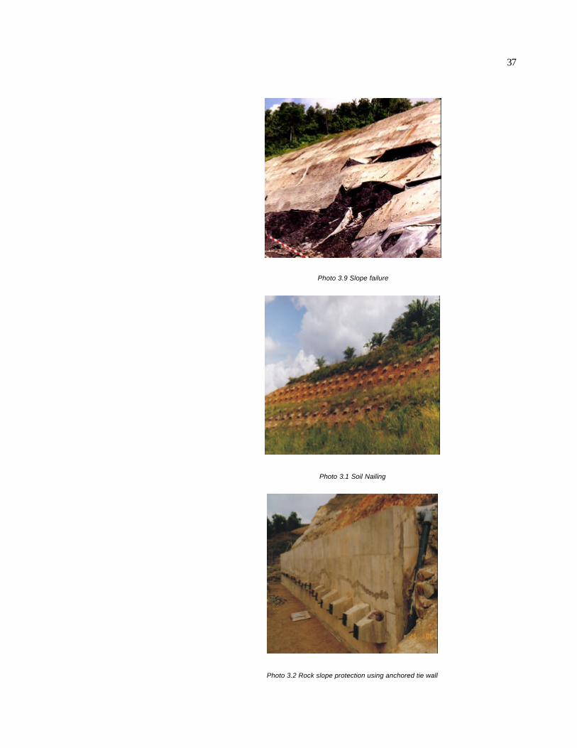
37
Photo 3.9 Slope failure
Photo 3.1 Soil Nailing
Photo 3.2 Rock slope protection using anchored tie wall

38
3. Mitigation Measures
Steps Activities Issues
Step 1 Assessment of Impacts
Step 2
Mitigation Measures Key mitigation measures include:
• Controlling slope erosion
• Slope stabilisation
• Proper landscaping Step 3 Monitoring
The purpose of this chapter is to assist in determining possible preventive, remedial or com-
pensatory measures for each of the adverse impacts evaluated as significant.
Mitigation will consist of a number of related actions and can take many forms, including the
following:
• Preventive - to be addressed during the pre-feasibility study and includes site selection,
orientation of layout and method of construction and landscaping
• Control - to be addressed during development and operational phases and relates to
working practices such as control of runoff and discharges
• Compensatory - whereby it is recognised that there will be an adverse impact and that
some compensation for the loss is to be made. This could include, for example, a spe-
cific contribution towards local community improvement projects.
This chapter covers
• Identification of the major mitigation measures for the key environmental impacts and
suggests implementation methodologies to be used to help minimise or eliminate the im-
pacts
• Description of other mitigation measures, including secondary, compensatory, rehabilita-
tion measures.
39
3.1 Key Mitigation Measures
Key mitigation measures for construction activity on hillslope include:
• Slope erosion control measures
• Slope stabilisation measures
• Landscaping measures.
Other relevant mitigation measures include:
• Air quality control
• Noise control
• Vibration control
• Wastewater and solid waste control.
3.2 Slope Erosion Control Measures
An erosion and sedimentation control plan (ESCP) is required to be submitted together with the
development plan proposal. The mitigating measures outlined in the ESCP should be as-
sessed for their effectiveness and practicality based on the assessment made during the EIA
study. Additional or more appropriate mitigating measures should be proposed to effectively
reduce the impact of slope erosion, particularly during the construction stage. Emphasis
should be given to mitigation measures that control at source rather than measures intended
for control of already eroded material.
Key mitigating measures to control slope erosion include:
1. Phased development. The project should be implemented in phases to keep land clear-
ance to a minimum. Only those areas required for development should be cleared. For this
purpose, a land clearance plan has to be drawn up showing the completion of each phase of
development and all clearing, grading and stabilisation operations should be completed before
moving on to the next phase. The construction specifications shall clearly define the maximum
length of time that a graded area will be left exposed and what short-term stabilisation methods
will be implemented in the event of lengthy delay. Where possible, all excavated topsoil shall be
stockpiled away from watercourses where they will not contribute to erosion, temporarily stabi-
lised and later used for revegetation. Phased development will reduce the amount of exposed
land at any one time.

40
An assessment should be made of the proposed phased development and amend-
ments/improvements should be made where appropriate.
2. Stabilisation and protection of exposed areas. Disturbed exposed areas should be stabi-
lised and protected from raindrop and runoff as soon as practicable to reduce exposure time.
Exposed slopes should be turfed as soon as possible so as to keep the interval between clear-
ing and revegetation to a minimum. The programme of protecting exposed slopes as contained
in the ESCP should be examined and assessed for its effectiveness and practicality.
3. Retaining existing vegetation cover. As much as possible of the existing vegetation
cover should be retained. Existing vegetation should be maintained as a filter along contours to
reduce velocity and improve water quality. When retained in construction sites, they break up
the length of long slopes and act as a buffer to minimise erosion. Stream buffers shall be re-
tained for rivers, the width of the buffers shall follow the existing Department of Irrigation and
Drainage (DID) regulations.
4. Timing of operations. Land clearing and cutting operations exposing bare slopes should be
carried out, wherever possible, during dry periods to minimise the impact of slope erosion. The
schedule of land clearing as proposed in the ESCP should be examined and appropriate
amendments/recommendations proposed.
5. Protection of cut and fill slopes. Cut and fill slopes should be protected with retention
structures or vegetation as soon as possible to minimise erosion of exposed material.
6. Construction of sedimentation ponds. Sediment within construction site should be re-
tained by the construction of temporary sedimentation ponds. The location and number of
sedimentation ponds as proposed in the ESCP should be assessed against the assessment
of soil erosion of the site. Ponds should be properly designed according to DID's (1975) speci-
fications to sufficiently trap and accommodate sediments transported by surface runoff. The
ponds should be regularly maintained by removing the deposited material at appropriate inter-
vals. Sediments removed from the ponds should not be placed or disposed near waterways.
7. Construction of drainage network. A network of drains should be installed to regulate
runoff within the site and also prevent runoff from adjacent areas from flowing into the site. Pe-
rimeter and feeder drains should be designed to cater for peak surface runoff. These drains
should be maintained by removing the deposited silt at regular intervals. The network and loca-
tions of drains as proposed in the ESCP should be assessed and additional drains might be
proposed to ensure proper regulation and control of runoff within the site.
8. Terracing and maintenance. Terracing should be carried out and the terraces properly
maintained. Cover crops should be established on the slopes of the platforms and walls of the
terraces immediately after commencement of earthworks.
The details of erosion and sedimentation control measures for a hillslope construction project
(after Guidelines for Construction in Hilly Areas, 1997) are stated in Annex E.
Table 3.1. Indicative rates for selected drainage works in Sabah
Control Measures Unit Rates (RM)

41
Roadside concrete drain 12" X12"
Roadside concrete drain 18" X 18"
m
m
60-85
80-100
Unpaved drain m 7-22
Culvert, 3 ft (900 mm) diameter m 280
Lined Sediment trap with gabions m3 600-800
Close turfing m 4
Geotextile layer m2 15-22
Table 3.2. Indicative rates for selected slope stabilisation works in Sabah
Control Measures Unit Rates (RM)
RC Retaining wall
RC Retaining wall with anchors
m
m
100-300
500-1000
Reinforced earth m 200-600
Anchored grid m 200-450
Removal of soil m3 6-12
Gunite wall
Gunite wall with anchors
m2
m2
60-100
250-600
3.3 Slope Stability Measures
The impacts of construction on the stability of slope and the surrounding environment can be
minimised by the provision of slope stabilisation measures. These measures should be carried
out even before commencement of construction so that the construction activities will not be
hampered by slope movement that may subsequently incur unnecessary costly remedial
works later.
The following criteria are considered applicable:
• Avoid the failure hazard. Where the potential for failure is beyond the acceptable level and
not preventable by practical means, as in terrain subject to massive planar slides or rock
and debris avalanches, the hazard should be avoided. Planned development on such
slopes or near the base should be avoided and relocated to areas where stabilization is
feasible
• Protect the site from failure. While it is not always possible to prevent natural slope fail-
ures occurring above a project site, it is sometimes possible to protect the site from the
runout of failed slope materials. This is particularly true for sites located at or near the
base of steep slopes. Methods include catchment and/or protective structures such as
basins, embankments, diversion or barrier walls and fences
• Reduce the hazard to an acceptable level. Unstable slopes affecting a project can be
rendered stable by increasing the factor of safety through the elimination of the slope, re-
moving unstable soil and rock materials, or applying one or more appropriate slope stabi-
lisation methods (such as buttress fills, subdrains, soil nailing, crib walls etc.). For deep-
seated slope instability, strengthening the design of structure is generally not by itself an
adequate mitigating measure.

42
The EIA consultant should evaluate all the proposed mitigation measures to stabilize all cut and
fill slopes, structures and unstables zones as contained in the development plan proposal for
their suitability and effectiveness. In this respect, expert opinion may be sought. If necessary, a
more effective and suitable mitigation measures have to be proposed.
The stabilisation method chosen depends largely on the type of instability, which is anticipated
at the project site, and its surrounding. Often there are multiple contributing factors that cause
or could cause slope failure or instability. Failure to identify the contributing causes could ren-
der the stabilisation work ineffective and recurrence of slope failure. The cost for implementing
such measures should also be considered; the most expensive method is not always the most
effective and vice versa. Frequently, the most economical and effective means of treating
slopes consist of a combination of two or more of the stabilisation techniques in conjunction
with selecting the most effective and economical stabilisation measures. Economy of time and
money are frequently key factors in the selection of stabilisation and mitigation methods.
The two general techniques used to stabilise slopes are (i) to reduce the driving force for fail-
ure, and (ii) to increase the resisting force.
1. Rock and Soil Falls. The principal failure mechanism is loss of cohesion or tensile strength
of the near-surface material on very steep slopes. Stabilisation methods include:
• Reduce the driving force by reducing the steepness of slope through grading, or by scal-
ing off overhang rock, diverting water from the slope face etc.
• Increase resisting force by pining individual blocks, covering the slope with mesh or net,
or installing rock anchors or rock bolts on dense spacing.
2. Slides, Slumps, Block Glides. The principal failure mechanism is loss of shear strength,
resulting in sliding of soil or rock mass along a rupture surface within the slope. Mitigating
measures include:
• Reduce the driving force by reducing the weight of the potential slide mass (cutting off the
head of the slide, or totally removing the landslide), flattening the surface slope angle
through grading, preventing water infiltration by controlling surface drainage, or reducing
the accumulation of subsurface water by installing subdrains
• Increase the resisting force, by replacing slide debris and especially the rupture surface
with compacted fill, installing shear keys or buttresses, dewatering the slide mass, pin-
ning shallow slides with rock anchors or bolts or by constructing retaining structures at
the edge of the slide.
3. Flows of debris or soil. The principal failure mechanism is fluidization of the soil mass,
commonly caused by the addition or increase water such as when the site is cleared and left
exposed for a long period. Reduction of this hazard include:
• Reduce driving force by removing potential debris from the site using grading or excavat-
ing procedures, or diverting water from debris so that it cannot be mobilized by means of
surface drains and/or subsurface drains
• Increase resisting force by providing buttresses together with subsurface drainage
• Protect site from failure by diverting the flow away using barriers or channels or by provid-
ing catchment structures to contain the slide material.

43
Table 3.2. Indicative rates for selected slope stabilisation works in Sabah.
Control Measures Unit Rates (RM)
RC Retaining wall m 100-300
RC Retaining wall with anchors m 500-1000
Reinforced earth m 200-600
Anchored grid m 200-450
Removal of soil m3 8-20
Gunite wall m2 60-100
Gunite wall with anchors m2 250-600
3.4 Landscape
Mitigating measures for impacts on the landscape should not only be concerned with damage
reduction but should include consideration of potential landscape visual enhancement. Wher-
ever possible design and layout that would enhance the landscape and visual quality should be
adopted.
Alternative designs that would avoid or alleviate the identified impacts on landscape, or that
would make the project visually compatible with the surrounding setting shall be thoroughly
examined before adopting other mitigating measure to reduce the adverse impacts.
Based on the impact assessment the EIA consultant should propose mitigation measures and
compare these with the proposed measures as stated in the development plan proposal. In this
respect, visualisation techniques can be used to make the comparison.
Possible mitigating measures include:
1. Preservation, e.g. preserving trees, green belts, landscape/ecological/architectural features
of high value and view corridor. Any tree with good amenity value unable to be retained should
be considered for its suitability for transplanting.
2. Architectural layout e.g. modifying the architectural layout so that the development is com-
patible with the surrounding environment.
3. Remedial, e.g. facade treatment, colour scheme and texture of materials used, use of non-
reflective material, screen painting and height.
4. Compensatory, e.g. landscape treatment, compensatory planting, creation of interesting
landscape of visual features to enhance the view and green corridor along access road.

44
3.5 Additional Mitigation Measures
3.5.1 Air Quality
If air quality is assessed to be a problem, the mitigation measures to control air pollution could
include:
• Dust Control: Systematic water spraying along access road under construction and at
construction site area. For normal days, water spraying frequency of two to four times a
day and for windy/dry days, frequency of more than six times a day
• Transportation control: Haul roads during the construction stage should be kept smooth,
well graded and cleaned. Avoid overloading and transported materials to be sheeted.
Wheel washing facilities should be provided at the entrance.
3.5.2 Noise
Where it is identified that noise is a problem, the following mitigation measures can be imple-
mented to reduce noise:
• Operating hours: Consideration should be given to controlling the times of construction
operations. Activities shall be planned accordingly to take into account of the sensitive
noise tolerance at night time (resting and sleeping period) and at day time (schooling pe-
riod)
• Notification: Awareness is an important factor in reducing noise-related annoyance. It
leads to preparedness and tolerance. Residents surrounding the construction site and
along the access road should be notified in advance of the operational activities
• Design control: Noisy semi-mobile and mobile machinery should be well maintained to
reduce noise emission. Installation of silencers should be considered. Baffle mounds or
fencing can be used to screen noisy operations at the construction site
• Transportation control: Transportation vehicles shall maintain appropriate travelling
speeds along the access road. Trees should be planted along the access road at the
start of its construction. Besides beautifying the road, they also function to reduce noise
from traffic.
3.5.3 Vibration
Air vibration due to blasting of rock outcrops can be minimised by the use of delay blasting
technique. A qualified shot firer should be engaged to carry out the blasting operation the de-
sign of which must be approved by the relevant government authority.
Impact pile driving to establish a base for foundations may give rise to high levels of ground
vibration. A study on the impact of ground vibration from pile driving should be conducted where
these operations occur within 50 metres of a building. If vibration is a nuisance, appropriate
actions should be taken. These include:
• Conducting the pile driving operation within as short a time as possible. At the same time,
the residents should be informed of the schedule of operation so that they are prepared
and aware. Awareness of such operation would make the residents more tolerant of the
elevated vibration levels

45
• Considering a change in the foundation design and method of pile driving. Bored piling,
which hardly produces any vibration, may be an alternative.
3.5.4 Wastewater and Solid Waste
Mitigation measures to prevent the discharge of untreated wastewater include:
• Installing temporary on-site septic tank system during the construction stage
• Permanent wastewater treatment system should be designed and built to comply with the
Ministry of Health Guideline/Recommendation for Sewerage Requirements for Housing in
Malaysia April 1983 and Code of Practice for Design and Installation of Sewerage System
Standard MS 1228:1991 and should comply with the limits of Standard of DOE's Sewage
and Industrial Effluents Regulation 1979.
Mitigation measures for solid waste disposal include:
• Providing sufficient bins to collect solid waste
• The solid waste bins should be regularly emptied and the solid waste collected should be
disposed off at sites approved by the Local Authority.
3.6 Secondary Rehabilitation Measures
In circumstances when it is not possible to restrict the scope of the development impact, miti-
gation measures can be employed off site to partially offset the adverse impact.
Possible secondary mitigation measures for construction activities on hillslope could include,
for example, community development projects e.g. playground or hiking trails for the benefit of
the people in the area.

46
Picture

47

48
4. Monitoring
Steps Activities Issues
Step 1 Assessment of Impacts
Step 2 Mitigation Measures
Step 3
Monitoring Environmental monitoring includes:
• Compliance monitoring
• Impact monitoring.
This chapter includes the following:
• Monitoring requirements to ensure compliance of the recommended mitigation measures
• Procedures for monitoring residual environmental impacts.
4.1 Compliance monitoring
Compliance monitoring is the one-time or periodic gathering of evidence to ensure that ap-
proval conditions are observed and complied with.
4.1.1 Slope Erosion Control
Compliance monitoring of approval conditions on slope erosion control could for example in-
clude the submission of the following evidence:
• Land clearing plan
• Revegetation plan
• Map showing locations of sedimentation ponds and drainage system
• Maintenance schedule of sedimentation pond and drainage system
• Photographs showing land clearing, revegetation, the installation of sedimentation ponds,
drainage system. The photographs should be taken from the same reference point.
These information should be submitted to ECD upon the completion of each phase of the de-
velopment until the project is completed.

49
4.1.2 Slope Stabilisation Control
Compliance monitoring of approval conditions on slope stabilisation control could for example
include the submission of the following evidence:
• Layout plan showing areas that need to be stabilised and the type of stabilisation work
• Planned schedule of stabilisation work constructions
• Date of completion of each stabilisation work
• Photographs showing the installation of stabilisation structures.
4.1.3 Landscape Mitigation Measures
Compliance monitoring of approval conditions on landscape impact could for example include
the submission of the following evidence (upon completion of each phase of the landscaping
plan):
• Map showing locations where vegetation and landscape/features of high value are pre-
served
• Map showing areas where replanting has taken place
• Photographs of changes in landscape.
The same fixed reference points as used during the impact assessment should be used.
4.2 Impact Monitoring
Based on the assessment of the environmental impacts of the project, the EIA consultant can if
feasible recommend impact monitoring, including locations where monitoring is to take place.
Impact monitoring involves the pre-measurement of environmental parameters during project
construction so as to detect changes in these parameters, which can be attributed to the pro-
ject.
4.2.1 Slope erosion and water quality
The impact of slope erosion may be monitored by reference to erosions pins or to water qual-
ity, particularly turbidity and total suspended solids content. The amount of the total suspended
solids of water from drainage lines would indicate the amount of silt being eroded from the site
and into the natural drainage system. Visual site checks can also be recommended, especially
during rainy periods, for signs of water quality deterioration that could be attributed to the pro-
ject.
4.2.2 Slope Failure
Visual on-site checks or other methods for determination of slope failure can be
recommended. This would include recommendation on the number, timing, technique and
location of the proposed method.

50
51
Annex A: Measurement of Slope Gradient
Area of influence. To determine whether a proposed site is located on a slope with gradient of
20 degrees or more, representative slope profiles should be drawn from a contour map. The
slope profiles should include the area of influence to the first sharp break in slope above and
below the site or at least a minimum 500 m upslope and downslope of the site whichever is
applicable. Topographic features might however indicate modifications to this general axiom.
Map scale. The accuracy of slope measurement is very dependent on map scale and contour
interval. A detailed topographic survey of the proposed site is normally carried out as part of the
planning process. Such detailed site topographical maps are produced on scales ranging from
1:1,500 to 1:500. These maps should be used in conjunction with the 1:12,500 (contour inter-
vals of 10 m) or nearest equivalent for the upslope and downslope areas produced by the
Lands and Survey Department to construct slope profiles. Such Lands and Survey maps are
available for most parts of Sabah.
Section Lines. Section lines of representative profiles should be selected so that they inter-
sect the locations of all proposed structures to be erected on the site and also existing land use
features (e.g. road, houses, telecommunication tower, etc.) upslope and downslope of the site.
The section lines should be orientated perpendicular to the steepest slopes. The number of
section lines will be dependent on the proposed site development and existing land use in the
vicinity.
Suggested Method. Construction of slope profiles involves plotting the elevations of contour
lines where they intersect the section lines. The suggested method of slope profile construction
is as follows:
1. Determine the alignment of the section lines. The section lines should start from the area
of influence upslope and follow the steepest gradient onto the site and across the pro-
posed constructions at the site and on to the area of influence downslope of the site. It is
recommended to construct multiple slope profiles, each profile across each proposed
construction at the site
2. A line is drawn on the contour map from upslope of the site and across the proposed
construction at the site and onto the downslope area as shown in the figure below. This
line provides the baseline ABC (attached example) for the graph; the length of this base-
line is equivalent to the length of area of influence as defined above
3. The points at which contour lines intersect the baseline are marked and their elevations
recorded. The vertical axis of the graph is scaled for elevation and constructed perpen-
dicular to the baseline; preferably, the vertical and horizontal scales should be similar to
show the true gradient of the slope. Points of elevation may now be plotted at the appro-
priate distances along the baseline. For precise plotting, intersecting lines may be drawn
from the corresponding values on the distance and elevation scale. Connecting the
points, a line profile of the slope is produced. The site boundaries, location of each pro-
posed construction on the site and existing construction on the upslope and downslope
areas, are marked on the profile

52
4. The profile may show sections of slope with varying gradients. The gradient of each slope
section should be measured. This can be easily determined by measuring directly with a
protractor the gradient of each slope section at the point of each slope break along the
profile
5. Repeat steps 2 to 4 to plot the slope profiles of the other section lines, in this example,
ADF and ADEG
6. If any of the slope section of the profiles has gradient of 20 degrees or more, then it is
concluded that the site is located on slope with gradient of 20 degrees or more.
Computer Analysis. Calculation of slope angle is straightforward using computer software.
The topographical base map can be converted into digital form and using computer software
such as SURFER, AUTOCAD, Geographic Information System (GIS), representative slope
profiles can be constructed.

53
Annex B: Development Proposals
Contents of the development proposal report for construction on hill slope projects
(after Guidelines for Construction in Hilly Areas, Ministry of Local Government and
Housing, 1997)
Item Particulars Investigation Results
1 Development concept and justifi-
cation
Useful to the local planning authority in considering
the proposal. It also assists the applicant in deter-
mining proposal, which is suitable and viable
2 Location plan and site plan To indicate the actual location of the site to be de-
veloped, its condition, present use, surrounding
development including available facilities
3 Land ownership details and limi-
tation of the land
To prove ownership of the land and the exact loca-
tion including information about the land for the pur-
pose of application to develop the land
4 Soil and environmental condition
of the land in respect of the fol-
lowing:
a) physical topography
b) landscape
c) geology and geotechnical
d) contour
e) water catchment area and
the runoff pattern
f) natural shape of the land
Present the natural conditions of the proposed de-
velopment area, including its topographical condi-
tion, vegetation, drainage etc. A slope map should
also be prepared.
5 Studies on trees and all vegeta-
tion which will be damaged by
the development
To present information on the trees and vegetation
existing on the land including investigation on how
far the development will impact on the flora and
fauna of the area
6 Details of the existing buildings
which may be damaged by the
development
To evaluate the existing buildings in the surrounding
area including the location and condition of these
buildings which may have historical or architectural
values
7 Land use analysis and the im-
pact of the development on the
surrounding
To evaluate how far the proposed development is
compatible with the present development on the
surrounding area
8 Layout plan with the following
details:
a) Development to any land:
i) protection and beautification
to the environment
ii) protection to the natural
topographical condition
iii) landscape proposal
How development activities incorporate steps to
protect and beautify environment.
Explanation on how earthworks of the proposed
development can be implemented with protection
measures to the natural topographical condition as
per the present Guidelines on Topographical Pro-
tection
Evaluation of the necessary landscaping measures

54
iv) the protection and replanting
tree proposal on the pro-
posed development
v) location and type of trees
and plants having a circum-
ference exceeding 0.8 m on
the proposed site
vi) provision for open space
vii) proposal for earthworks
viii) details of works programme
b) development in conjunction
with buildings having archi-
tectural or historical value
i) particulars to identify the
building
• its uses
• its condition
• its characteristics
• its looks
• its construc tion
• its shape
ii) particulars on the following
steps:
• protection
• beautification
• maintenance
c) development which affects
buildings, details on charac-
teristics and looks of build-
ings in the area surrounding
the site
d) any other conditions set by
local planning authority
with the aim of enhancing the comfort of the envi-
ronment
Evaluation of how activities take into account steps
to protect and replant trees which may be damaged
as per current Guidelines for Tree Protection
Identification of trees classified under section 35H
of the Town and Country Planning Act (Amendment
1995) A 933. Under this section, all trees with cir-
cumference exceeding 0.8 m shall not be cut
unless written approval has been given by the local
authority
Evaluate provision of open space in accordance
with current standard
Clarification on steps to control earthworks to pre-
vent excessive soil erosion
Explanation on what steps to be taken to control
earthworks to prevent excessive soil erosion, es-
pecially during the operation phase which may im-
pact on the physical environment
Evaluation of the importance of existing buildings in
the vicinity of the development area. This is to de-
termine if the buildings should be preserved as per
guidelines for Building Protection, Historical and
Architectural Sites
Evaluation of suitability of proposed development
with that of the current development in the sur-
rounding area as per current planning guidelines
The local planning authority may request for any
other matters which may be useful for considera-
tion in the approval application
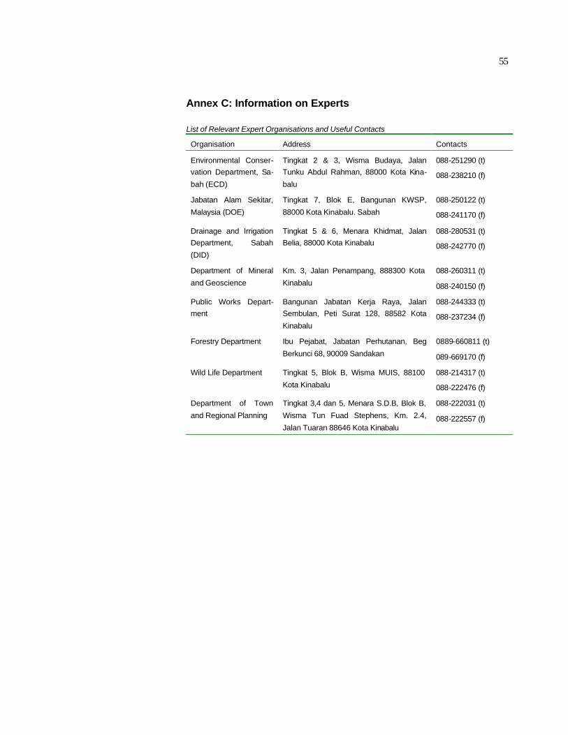
55
Annex C: Information on Experts
List of Relevant Expert Organisations and Useful Contacts
Organisation Address Contacts
Environmental Conser-
vation Department, Sa-
bah (ECD)
Tingkat 2 & 3, Wisma Budaya, Jalan
Tunku Abdul Rahman, 88000 Kota Kina-
balu
088-251290 (t)
088-238210 (f)
Jabatan Alam Sekitar,
Malaysia (DOE)
Tingkat 7, Blok E, Bangunan KWSP,
88000 Kota Kinabalu. Sabah
088-250122 (t)
088-241170 (f)
Drainage and Irrigation
Department, Sabah
(DID)
Tingkat 5 & 6, Menara Khidmat, Jalan
Belia, 88000 Kota Kinabalu
088-280531 (t)
088-242770 (f)
Department of Mineral
and Geoscience
Km. 3, Jalan Penampang, 888300 Kota
Kinabalu
088-260311 (t)
088-240150 (f)
Public Works Depart-
ment
Bangunan Jabatan Kerja Raya, Jalan
Sembulan, Peti Surat 128, 88582 Kota
Kinabalu
088-244333 (t)
088-237234 (f)
Forestry Department Ibu Pejabat, Jabatan Perhutanan, Beg
Berkunci 68, 90009 Sandakan
0889-660811 (t)
089-669170 (f)
Wild Life Department Tingkat 5, Blok B, Wisma MUIS, 88100
Kota Kinabalu
088-214317 (t)
088-222476 (f)
Department of Town
and Regional Planning
Tingkat 3,4 dan 5, Menara S.D.B, Blok B,
Wisma Tun Fuad Stephens, Km. 2.4,
Jalan Tuaran 88646 Kota Kinabalu
088-222031 (t)
088-222557 (f)
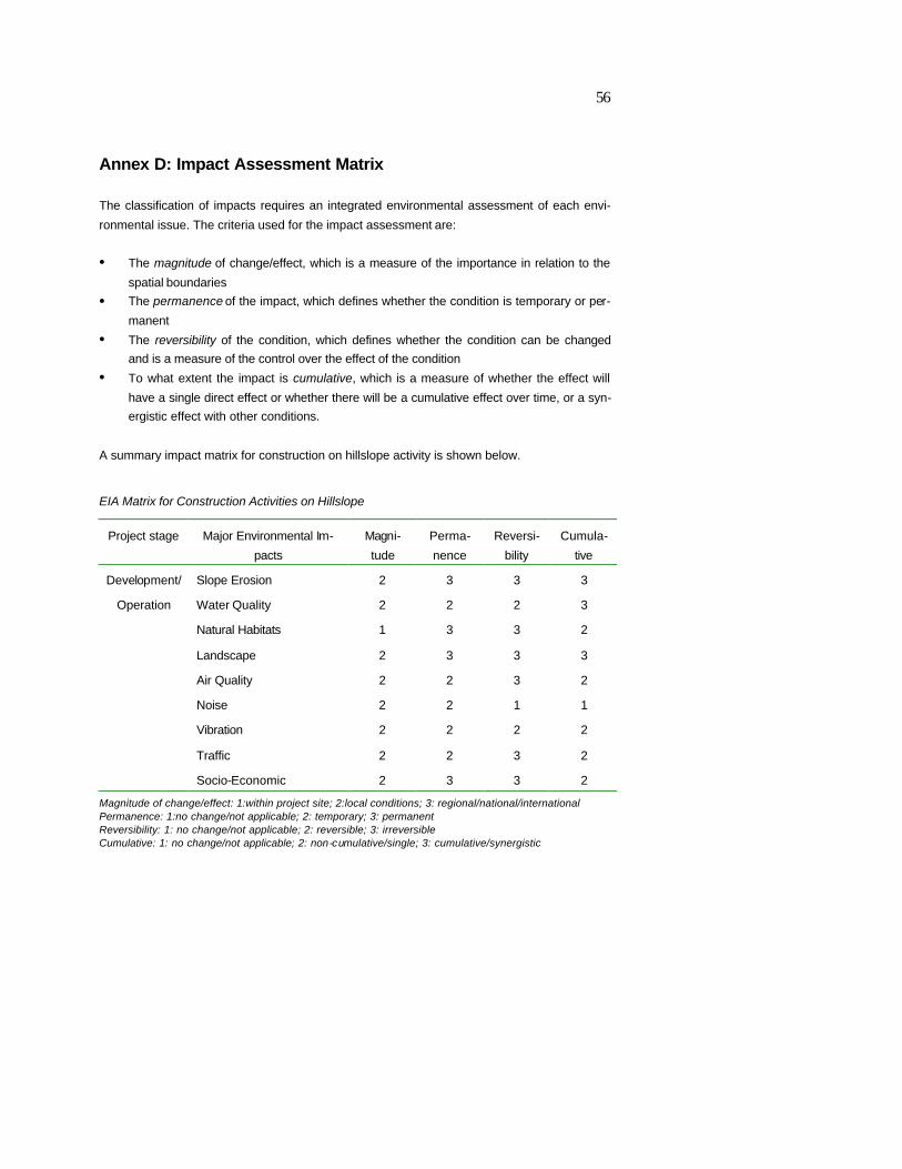
56
Annex D: Impact Assessment Matrix
The classification of impacts requires an integrated environmental assessment of each envi-
ronmental issue. The criteria used for the impact assessment are:
• The magnitude of change/effect, which is a measure of the importance in relation to the
spatial boundaries
• The permanence of the impact, which defines whether the condition is temporary or per-
manent
• The reversibility of the condition, which defines whether the condition can be changed
and is a measure of the control over the effect of the condition
• To what extent the impact is cumulative, which is a measure of whether the effect will
have a single direct effect or whether there will be a cumulative effect over time, or a syn-
ergistic effect with other conditions.
A summary impact matrix for construction on hillslope activity is shown below.
EIA Matrix for Construction Activities on Hillslope
Project stage Major Environmental Im-
pacts
Magni-
tude
Perma-
nence
Reversi-
bility
Cumula-
tive
Development/ Slope Erosion 2 3 3 3
Operation Water Quality 2 2 2 3
Natural Habitats 1 3 3 2
Landscape 2 3 3 3
Air Quality 2 2 3 2
Noise 2 2 1 1
Vibration 2 2 2 2
Traffic 2 2 3 2
Socio-Economic 2 3 3 2
Magnitude of change/effect: 1:within project site; 2:local conditions; 3: regional/national/international Permanence: 1:no change/not applicable; 2: temporary; 3: permanent Reversibility: 1: no change/not applicable; 2: reversible; 3: irreversible Cumulative: 1: no change/not applicable; 2: non-cumulative/single; 3: cumulative/synergistic

57
Annex E: Control Measures of Slope Gradient
Details of erosion and sedimentation control measures (after Guidelines for Construction
in Hilly areas, 1997, Ministry of Local Government and Housing with slight modifications)
No. & Subject Related
Issues
Details
1. Minimising soil erosion
i) Before construction Preventive measures shall be put in place to minimise erosion
through the preparation of: (i) Preliminary site evaluation, (ii) Ero-
sion and Sediment Control Plan
ii) Reducing work area The working area for various facilities within a construction site
should be kept to less than twice the plinths of the building
iii) Regulate phase of
development
Development schedule must be clearly defined. Completion date
for each phase of development shall be indicated and all clearing,
grading and stabilisation operations shall be completed before
moving onto the next phase
iv) Timing of construction
activities
Timing of construction activities shall, wherever possible, be
spread evenly over the development timescale to ensure that the
deleterious effects arising from construction activities are mini-
mised
v) Hydrological and cli-
matic conditions
Construction activities shall take into consideration the hydrological
and climatic conditions experienced in the area, in particular the
rainfall and runoff patterns
vi) Existing vegetation Existing vegetation shall be maintained as filters along contours to
reduce velocity and improve water quality. When retained in con-
struction sites, they break up the length of long slopes and act as
buffers to minimise erosion
vii) Stream buffer Stream buffers shall be retained for rivers, the width of the buffers
shall follow the DID regulations. For small streams within the con-
struction site, the following could be used as guide: (i) Undulating
to moderate water course with and average Grade of Basin < 15
degrees: Intermittent stream buffer from 10-20 m; (ii) Steep to very
steep water course with and average Grade of Basin > 15 de-
grees: Permanent stream buffer from 20-30 m
2. Preserving the topsoil and other assets
i) Sensitive ecological
area
Sensitive ecological areas within a construction site such as salt
licks, natural springs, unusual rock outcrops etc. shall be demar-
cated and preserved
ii) Archeological sites All known archeological sites within the construction site shall be
demarcated and preserved. Advise from the Curator of Museum
should be sought
iii) Flora and fauna All known rare and endemic flora and fauna areas or niches within
the construction site shall be demarcated and preserved
iv) Topsoil All excavated topsoil and nutrients shall be stockpiled and later
used for revegetation. Topsoil should be stockpiled in areas where
it will not contribute to erosion and sedimentation. Temporary
stabilisation is necessary for exposed stockpiles.

58
v) Trees All trees that are rare shall be fenced and preserved or carefully
uprooted and transferred to a nursery/another site for replanting.
Expert advice should be sought from the Department of Forestry
or Forest Research Institute of Malaysia
3. Access routes
i) Right-of-ways a) All right-of-ways or access routes shall be shown on the ESCP
and it shall be the responsibility of the Project Proponent to ensure
that all vehicular traffic stay within the designated right-of-ways. b)
Access roads should be kept to a minimum with other areas off
limit to traffic
ii) Roads and permanent
storm drains
Roads and permanent storm drains should be installed as early as
possible so that they can control runoff during construction. How-
ever, they should be temporarily connected to the sediment basins
until stabilisation of graded areas is achieved
iii) Road shoulders Road shoulders are to be protected mechanically or vegetatively
against erosion
iv) Construction of all
new main and secondary
timber extraction roads
Construction of all main and secondary timber extraction roads
and any such access must be carried out with the written permis-
sion of the enforcement authority and in accordance with specifi-
cations laid down by the said authority. These accesses should as
far as possible follow natural contours
v) Movement of construc-
tion vehicles over unsur-
faced roads
All movement of construction vehicles over unsurfaced roads and
areas should be kept to a minimum. Haul roads should be sprayed
with water to reduce dust pollution during dry periods
vi) Paving of access road All access roads to the site shall be paved for a distance of 10
metres where these access roads join the existing roads
vii) Exit points All vehicles should enter and leave the construction site at a limited
number of points. The exit points should provide for the washing of
vehicles as they leave. The washing bay should be the full width at
the exit
4. Drainage control at construction sites
i) Principles Runoff water should be directed so that it does not run across
disturbed and unstable areas
ii) Hydraulic characteris-
tics of the drainage sys-
tem
Locate and study the hydraulic characteristics of the drainage sys-
tem which include: i) overall drainage pattern, ii) dimensions and
flow of rivers and streams, iii) springs and wells including flow and
well logs, iv) subsurface conditions including aquifer type and ca-
pacity, depth to water table and location of perched water table and
flow pattern of groundwater, v) salt water intrusion areas, vi) natu-
ral drainage depressions, basins and sinks, vii) flood plains, both
on-site and downstream, that will undergo change due to grading
and construction
iii) Drainage routes and
channels
Construct drainage routes and channels in such a way that the
beds do not themselves degrade and so contribute to the sedi-
mentation problems
iv) Removal of
accumulation of
sediment load
Remove the sediment load accumulated in channels during the
dry season to avoid downstream sedimentation
v) Slope drains For hillside areas, slope drains must be constructed or extended
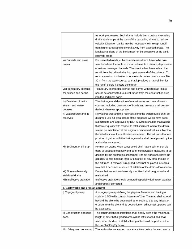
59
as work progresses. Such drains include berm drains, cascading
drains and sumps at the toes of the cascading drains to reduce
velocity. Diversion banks may be necessary to intercept runoff
from higher areas and to divert it away from exposed areas. The
longitudinal slope of the bank must not be excessive or the bank
itself will erode
vi) Culverts and cross
drains
For unsealed roads, culverts and cross drains have to be con-
structed where the route of a road intercepts a stream, depression
or natural drainage channels. The practice has been to lead the
runoff from the table drains into upstream end of the culverts. To
reduce erosion, it is better to locate table drain culverts some 20-
30 m from the watercourse, so that it provides a natural filter for
the runoff before it enters the stream
viii) Temporary intercep-
tor ditches and berms
Temporary interceptor ditches and berms with filters as inlets
should be constructed to direct runoff from the construction area
into the sediment basin
ix) Deviation of main-
stream and water-
courses
The drainage and deviation of mainstreams and natural water-
courses, including provisions of bunds and culverts shall be car-
ried out wherever appropriate
x) Watercourse and its
reserves
No watercourse and the reserves along the watercourse shall be
disturbed until full plan details of the proposed works have been
submitted to and approved by DID. A system shall be maintained
that water quality with respect to total sediment load at the down-
stream be maintained at the original or improved values subject to
the satisfaction of the authorities concerned. The silt traps that are
provided together with the drainage works shall be approved by the
authorities concerned.
xi) Sediment or silt trap Permanent drains when constructed shall have sediment or silt
traps of adequate capacity and other conservation measures to be
decided by the authorities concerned. The silt traps shall have the
capacity to hold not less than 10 cm of silt at any time, the silt, in
the silt traps, if removal is required, shall not be placed in such a
way that it becomes a source of siltation of the drains downstream
xii) Non mechanically
stabilised drains
Drains that are not mechanically stabilised shall be grassed and
maintained
xiii) Ineffective drainage Ineffective drainage should be noted especially during wet weather
and promptly corrected
5. Earthworks and erosion control
i) Topography map A topography map defining the physical features and having a
scale of 1:500 with contour intervals of 2 m. The map shall extend
beyond the site to be developed far enough so that any impact of
erosion from the site and its deposition on adjacent properties can
be assessed.
ii) Construction specifica-
tions
The construction specifications shall clearly define the maximum
length of time that a graded area will be left exposed and shall
state what short-term stabilisation practices will be performed in
the event of lengthy delay.
iii) Adequate conserva- The authorities concerned may at any time before the earthworks

60
tion measures may be continued to the next phase requires adequate detailed
conservation measures. The standards and specifications of such
conservation measures shall be in accordance with the specifica-
tions of DID.
iv) Extraneous runoff Extraneous runoff shall be directed away from the exposed soils
by drains
v) Contour plough or
deep-rip
Contour plough or deep rip so as to leave a rough surface to in-
crease infiltration
vi) Protection cover Provide protection covers such as vegetation and plastic sheets
on exposed areas
vii) Earthworks Earthworks should be confined to periods of low expected precipi-
tation
viii) Exposed area As small an area as practical should be exposed and graded at a
time. The size of the area will depend on the potential erodibility of
the soil and the time required to stabilise the area after grading is
completed
ix) learing and grading Clearing and grading should be done with care to protect and
maintain the previously installed temporary control measures
x) Fills Fills should be placed in horizontal layers and the faces of the fill
slopes should be maintained as filling progresses. The materials
to be used and the degree of compaction shall be clearly specified
xi) Landscape Where it is intended that cleared ground is to be planted, then the
area should be landscaped and the planting carried out as soon as
possible even prior to the completion of the whole work
xii) Cutting of trees Trees and other vegetation should not be cut or cleared until the
earthwork site is ready to be worked. The cleared ground shall be
revegetated (turfed) within three months after commencement of
earthworks during the dry season and within one month after
commencement of earthworks during the wet season
xiii) Gradient of cutting Maximum gradient of cuts shall vary with soil texture. However,
measures taken should ensure that slumping shall not occur
xiv) Land clearing and
soil cultivation
Land clearing and soil cultivation shall only take place in the dry
season. Immediately after clearing, conservation measures shall
be installed. This shall include silt traps and the maintenance
and/or establishment of a vegetative belt of at least 2 chains away
from he edge of permanently flowing waterway. There shall be no
obstruction whatsoever to flow of water by felled timber or other
debris
xv) Disposal of unsuit-
able materials and sur-
plus earth
Unsuitable materials and surplus earth shall be disposed off in
designated spoil tips. In the event additional disposal areas (spoil
tips) are required, the contractor shall be responsible for identifying
theses disposal areas to be approved by the Site Officer
xvi) Deposit of cleared
vegetation and debris
On no account should cleared vegetation and debris be deposited
or pushed into watercourses, streams and rivers
xvii) Backfilling of holes
and cavities
Holes and cavities resulting from the clearing, grubbing, destump-
ing and derooting shall be backfilled with acceptable materials and
compacted to approximately densities of adjacent areas
xviii) Design of batters Batters or terraces represent a special and severe case of ex-

61
posed surface after earthworks. The resistance of the batter to
erosion will be determined primarily by the engineering design.
Batters must be designed to satisfy criteria. For stable soils, a
batter slope of 2H : 1V is recommended
6. Sediment prevention and control
i) Sediment ponds Wherever feasible, sediment retention ponds, basins or sediment
ponds shall be installed. They should be adequately sized and
constructed prior to start of earthworks
ii) Silt traps Small temporary silt traps operate by slowing of stopping runoff at
some point on its route, causing it to deposit its sediment load.
These shall be constructed across drainage lines near the plinths
of building. Allowance must be made for sediment removal and the
sediment must be deposited in a suitable area in such a manner
that it will not slide back into the traps
iii) Infiltration and ponding
basins and stormwater
ponds
Infiltration ponding basins and stormwater ponds can be temporar-
ily used as sediment basins, provided they are satisfactorily main-
tained and cleaned out after construction to ensure efficient opera-
tion as designed
iv) Temporary control
measures
Silt traps and other temporary control measures should only be
removed and dismantled when the permanent vegetative cover
and control measures are satisfactorily established
v) Mitigatory measures Where necessary, mitigating measures such as silt traps, water
bars and side drains shall be constructed in all hauling roads in
order to reduce siltation into natural waterways
7. Slope stabilisation
i) Critical areas along
streams
All critical areas along streams and gullies must be marked on the
ESCP and the recommended methods of stabilisation indicated
ii) Stream stabilisation Stream stabilisation shall be scheduled during periods of dry
weather flow whenever possible
iii) Stabilisation of water-
ways
The stabilisation of waterways shall be defined giving both tempo-
rary and permanent practices, which state where and when sod-
ding, temporary seeding and permanent seeding are to be used.
The specifications shall include ground preparation, sod quality,
seed type and quality, fertilisation and mulching
iv) Temporary retaining
structure
In cases where permanent retaining structure or stabilisation of
slopes are exempted by the authorities concerned, there shall be
provided temporary retaining structures or stabilisation of slopes
during the continuance of such earthwork
v) Protection of slope Slopes are to be protected against erosion
vi) Irrigation of cut and fill
slopes
Cut and fill slopes should be regularly irrigated and fertilised to
encourage faster growth. Development should proceed with mini-
mum disturbance of the planted areas and temporary control
measures
vii) Protection for walls of
cuts
Walls of cuts are to be protected with vegetation and/or chemical
stabilisers and/or approved retention structures. Wherever neces-
sary, non-permanent retention structures need to be maintained in
order to ensure that erosion shall not aggravate. Vegetation, if
used, shall establish complete cover

62
viii) Interference of natu-
ral waterways
There shall be no obstruction or interference with the natural wa-
terways. Where a road is to be cut across a river or stream,
bridges and culverts as prescribed by the enforcement authority
shall be constructed and maintained according to specifications
ix) Terracing of hilly land For hilly land, terracing shall be done and maintained. Cover plants
shall be established on the slopes of the platforms and walls of the
terrace immediately after commencement of earthworks
x) Raising the top of
spillways
No person shall employ any means of temporarily raising the top of
any spillways without the sanction of the authority concerned

63
Annex F: Statutory Controls
Annex Table 1. Legislation
Legislation Controlling Authority
Conservation of Environment (Prescribed Activi-
ties) Order 1999
Environmental Conservation Depart-
ment, Sabah
Environmental Quality (Prescribed Activities) (En-
vironmental Impact Assessment) Order 1987
Department of Environment Malaysia
Land Ordinance 1930 Lands and Survey Department, Sabah
Water Resources Enactment 1998, Sabah Drainage and Irrigation Department
Water Supply Ordinance 1961 Jabatan Air, Sabah
Town and Country Planning Ordinance 1950 Town and Regional Planning Depart-
ment, Sabah
Local Government Ordinance 1961 Local Authorities
Conservation of Environment (Prescribed Activities) Order 1999. Section 3: Any person
who intends to undertake any of the prescribed activities shall submit to the Director a report,
which is to be prepared by such expert or authority as may be approved by the D irector – (a)
On the impact of such activities on the environment and on the sustainable utilisation, preser-
vation and management of the natural resources of the State; and (b) On the measures being
preventive, mitigating or abatement to be taken for the protection and enhancement of the envi-
ronment. Section 4: Such report shall be submitted to the Director and shall be in the approved
Form as specified in the Second Schedule hereto, which may be used with such modifications
as may be required, depending upon the circumstances of each particular case. First Sched-
ule – Prescribe Activities: Section 3 (vi): construction of buildings for commercial purposes or
buildings exceeding 4 storeys high for residential purposes on hills with slopes having gradient
of 20 degrees or more; Section 7 (I) construction of parks, resorts or other recreational facilities
or major roads on hills with slopes having gradient of 20 degrees or more.
Environmental Quality (Prescribed Activities) (Environmental Impact Assessment) Or-
der 1987. Section 2: The activities specified in the Schedule are prescribed to be prescribed
activities. Schedule, Section 17 (b): Hill station or hotel development covering an area of 50
hectares or more.
Land Ordinance 1930. Part I, Section 26(2): The Government also has power to reserve such
portion of land as may be deemed advisable along the banks of rivers, streams or creeks, or
along the seashore above high water mark, or along the ridges of hills. Such reservations shall
be shown on all documents of title.
Water Resources Enactment 1998. Part IV, Section 17(1): No person shall, unless author-
ised by a licence for a water activity or otherwise authorised in accordance with this Enac t-
ment, engage in a water activity, meaning to – (a) take or use water from a water body; (b)
return water to a water body directly or indirectly by artificial means; (c) control, divert or miti-

64
gate flood waters outside a floodplain management area referred to in Part VI of this Enact-
ment; or (d) carry out a water body alteration activity. Part VI, Section 38 (1): This section ap-
plies where, on the recommendation of the Council, the Yang di-Pertua Negeri is satisfied that
it is necessary to control, limit or modify activities within an area of land, to prevent the pollution
or degradation of surface water or groundwater, or the loss of its availability, or to protect a
water body or an aquifer for which a catchment management plan or other investigation has
identified that protection is required. Part VII, Section 40(1): From the date of the commence-
ment of this Enactment, river reserves and shore reserves are established on land, which is –
(a) in the case of river reserves, within twenty metres of the top of the bank of every river, in-
cluding its estuary, where the river channel is not less than three metres in width; and (b) in the
case of shore reserves, within twenty metres of the bed of all coastal waters. Part VII, Section
41(1): Within a river reserve or shore reserve or on, in or above a water body it is an offence to
undertake, without the approval in writing of the Director, any activity, which involves –(a) the
removal of natural vegetation or the removal or deposition of material; (b) the erection of a
structure or building; or (c) the carrying out of a commercial or agricultural activity, unless the
activity is of a type, which the Director has declared in writing, does not require approval.
Water Supply Ordinance 1961. Part VII, Section 25 (1): Any person who deposits or allows to
be deposited any earth, material or liquid in such manner or place that it may be washed, fall or
be carried into any waterworks shall be guilty of an offence and shall be liable to a fine of five
hundred ringgit.
Town and Country Planning Ordinance 1950. Part I, Section 3 (2): The duties of the Board
shall be to consider all schemes submitted to it by Local Authorities, to make recommenda-
tions thereon to the Yang di-Pertua Negeri, to advise the Yang di-Pertua Negeri generally on the
development of land and to supervise and control Local Authorities in the exercise of the pow-
ers and duties conferred and imposed upon them by this Ordinance. Part III, Section 15(1):
Subject to the succeeding provisions of this section, as from the material date no person shall,
within the jurisdiction of any Local Authority, carry out any development of land or any construc-
tion, demolition, alteration, extension, repair or renewal of any building until six months after an
approved scheme takes effect for the area containing such land or building. Part IV, Section 19
(1): Subject to the provisions of this section, the Local Authority may at any time –(a) remove,
pull down or alter so as to bring into conformity with the provisions of an approved scheme, any
building or other work which does not conform to those provisions, or the removal, demolition
or alteration of which is necessary for carrying an approved scheme into effect, or in the erec-
tion or carrying out of which any provision of an approved scheme has not been complied with;
or (b) where any building or land is being used in such manner as to contravene any provision
of an approved scheme, prohibit it from being used; or (c) where any land has since the mate-
rial date been put to any use which contravenes any provision of an approved scheme, rein-
state the land;
Local Government Ordinance 1961. Section 49 (6): take all necessary measures for the
prevention of soil erosion and the protection of crops; Section 46 (23): regulate and control all
buildings and building operations and the repair and removal of ruinous and dangerous build-
ings and subject to any written law relating to town planning, prohibit the erection of a building of
a particular class, design or appearance in particular districts, localities or streets or portions of
streets;

65
Annex G: Glossary of Terms
building means any building, erection or structure on any land and where the context so per-
mits, includes the land on which the building is situate
Central Board means the Central Town and Country Planning Board constituted under the pro-
visions of Section 3 of the Town and Country Planning Ordinance
dB(A) means decibel-A-weighted, a unit of measurement of sound level corrected to the A-
weighted scale using a reference level of 20 micropascals
development means any land development which involve the construction of infrastructure
activities, any structure and any related action or disturbance to the natural earth conditions
discontinuity means interruption, usually of a planar nature, to the homogeneity of a rock mass
(i.e. joints, faults)
effluent means any discharge either sewage or industrial effluent by an operation to the receiv-
ing environment
environment means the physical factors of the surroundings of the human beings including
land, water, atmosphere, climate, sound, odour, taste, the biological factors of animals and
plants, and the social factor of aesthetics
factor of safety means the ratio of average available strength of the soil along the critical slip
surface to that required to maintain equilibrium
fault is a fracture in rock along which there has been an observable amount of displacement
foundation means a system or arrangement of foundation units such as footing, raft or pile
through which the loads from a building or structure are transferred to the supporting soil or
rock
landslide or landslip is a rapid movement of earth materials separated from the underlying sta-
tionary part of the slope by a definite surface
Local Authority means any District Council, Town Board or Municipal Council established un-
der the provision of Section 3 of the Local Government Ordinance 1961
Local Plan means the local plan for an area, and any alteration of the plan for the time being
having effect in the area by virtue of sub-clause (11) of Clause 10 of the Town and Country
Planning Ordinance
mudflow or earthflow is mass movement involving high water content
natural resources means air, biological diversity of resources, oil, gas, forest and forest pro-
duce, land, rocks, soils, sub-soils, animals, birds, plants, marine or aquatic life, and waters of
the State of Sabah

66
pollutants means any natural or artificial substances, whether in solid, semi-solid or liquid form,
or in the form of gas or vapour, or in a mixture of at least two of these substances, or any ob-
jectionable odour or noise or heat emitted, discharged or deposited or is likely to be emitted,
discharged or deposited from any source which can directly or indirectly cause pollution and
includes any environmentally hazardous substances
pollution means any direct or indirect alteration of the physical, thermal, chemical, biological, or
radioactive properties of any part of the environment by discharging, emitting, or depositing
wastes so as to affect any beneficial use adversely, to cause a condition which is hazardous or
potentially hazardous to public health, safety, or welfare, or to animals, birds, fish or aquatic life,
or to plants
residual impact means the potential environmental impact remaining after mitigating measures
have been adopted into a project plan
resort means a place fequented ususally for specified purpose or quality e.g. health, holiday,
mountain, seaside.
river reserve means a reserve within twenty metres of the top of the bank of every river, includ-
ing its estuary, where the river channel is not less than three metres in width
rockfall means movement of blocks of solid rock
soil creep is a shallow, slow-moving form of an earth flow involving thin layers of near-surface
soil
sound level means ten times the common logarithm of the ratio of the square of the measured
A-weighted sound pressure to the square of the standard reference pressure of 20 micropas-
cals
visual receivers means groups of people who are sensitive to changes in their views

67
References
Construction Industry Research and Information Association (1994). Environmental Assessment. London,
U.K.
Dix, H.M. (1981). Environmental Pollution . John Wiley & Sons Ltd., New York.
Environment Australia. 1998). Landform Design for Rehabilitation. Department of the Environment Austra-
lia.
Environmental Conservation Department Sabah (ECD) (2000). Handbook for Environmental Impact As-
sessment (EIA) in Sabah. Draft. Kota Kinabalu.
Environmental Protection Department (1997). Technical Memorandum on Environmental Impact Assess-
ment Process (Environmental Impact Assessment Ordinance Cap. 499, S. 16). Environmental
Protection Department, Hong Kong, 83 pp.
Geotechnical Engineering Office, Hong Kong (1979). Geotechnical Manual for Slopes. Hong Kong Gov-
ernment Printer, Fourth Reprint, February 2000, 297 p.
Huszar Brammah and Associates. (1983). Kota Kinabalu Urban Pre-planning Studies: Comprehensive
Development Plan 1990.
Styles, K.A. and Hansen, A. (1989). Geotechnical Area Studies Programme, Territory of Hong
Kong.Geotechnical Control Office, Civil Engineering Services Department, Hong Kong. GASP
Report XII.
Government of Malaysia (1974; Amends, 1985; and Amends, 1996). The Environmental Quality Act.
Kuala Lumpur.
Jabatan Alam Sekitar (DOE). 1995. Environmental Impact Assessment Guidelines for Development of
Resort and Hotel Facilities in Hill Stations . Kuala Lumpur.
Jabatan Alam Sekitar (DOE) (1996). Guidelines for the Prevention & Control of Soil Erosion & Siltation in
Malaysia. K Lumpur.
Jabatan Alam Sekitar (DOE) (undated). Buku Panduan Kawasan Sensitif Alam Sekitar di Malaysia. K
Lumpur.
Jabatan Kerajaan Tempatan (1997). Garis Panduan Pembangunan di Kawasan Bukit. Kementerian
Perumahan dan Kerajaan Tempatan. Kuala Lumpur.
Jabatan Penyisatan Kajibumi Malaysia. Geological Inputs for Environmental Impact Assessment (Unpub-
lished).
Jabatan Pengairan dan Saliran. (1975). Urban Drainage Design Standards and Procedures for Peninsular
Malaysia. Kuala Lumpur.
Lim, R.P. and Lee, S.W. (eds). 1992. Hill Development: Proceedings of the Seminar, 1 December 1991:
Malayan Nature Society, Kuala Lumpur.
Kementerian Tempatan dan Perumahan Sabah. (1998). Garis Panduan Pembangunan di Kawasan Bukit.
Kota Kinabalu.
Krenkel, P.A. and Novotny, V. (1980). Water Quality Management. Academic Press Inc., U.S.A.
Marsh, W.M. (1969). Environmental Analysis for Landuse and Site Planning. McGraw-Hill Book Co. New
York.

68
MPKK, PAM and IEM. (1997). Guidelines for Submission of Plans for Approval: Procedure and System
on Processing of Occupation Certificate and Handing over of Services to Majlis Perbandaran
Kota Kinabalu (Draft 3).
Morgan, R.P.C. (1979). Soil Erosion. Longman Inc., New York.
Morgan, R.P.C. (1995). Soil Erosion and Conservation. Longman Inc., New York.
Olofin, E.A. (1974). Classification of slope angles for land planning purposes. Journal of Tropical Geogra-
phy, 39, p. 72-77.
Rau, J.G. and Wooten, D.C (1980). Environmental Impact Analysis Handbook . Mc Graw-Hill, New York.
Roslan, Z.A and Tew, K.H. (1997). Soil erosion studies at Jalan Indah 1/1, Taman Universiti Indah, Seri
Kembangan, Selangor Darul Ehsan.
Sidle, R.C., Pearce, A.J. and O’Loughlin, C.L. 1985. Hillslope Stability and Land use: American Geo-
physical Union> Water Resources Monograph Series 11.
Small, R.J. (1983). The Study of Landforms . 2nd Edition. Cambridge University Press , New York.
State of Sabah (1930). Land Ordinance 1930. Kota Kinabalu
State of Sabah (1950) Town and Country Planning Ordinance 1950. Kota Kinabalu
State of Sabah (1956) Drainage and Irrigation Ordinance, 1956. Kota Kinabalu
State of Sabah (1961). Water Supply Ordinance 1961. Kota Kinabalu
State of Sabah (1961). Local Government Ordinance 1961. Kota Kinabalu
State of Sabah (1996). Conservation of Environment Enactment 1996. Kota Kinabalu.
State of Sabah (1998). Sabah Water Resources Enactment 1998. Kota Kinabalu.
State of Sabah (1999). Conservation of Environment (Prescribed Activities) Order 1999. Kota Kinabalu
Tew, K.H. (1996). Production of Malaysian Soil Erodibility Nomograph in relation to soil erosion issues . M.
Eng. Thesis Dissertation, UTM Skudia, Johor.
U.S.G.S. (1994). Look Before You Build. U.S.G.S Circular No. 1130.
VT Soil Erosion Research & Consultancy (2000). Cadangan Pembinaan di atas Lot 50 Seksyen 3, Mukim
Brinchang Cameron Highlands Pahang Darul Makmur.
World Bank (1991). Environmental Assessment Sourcebook Vol. II Sectoral Guidelines . TP No 140,
Washington, D.C., U.S.A..
World Health Organisation (1982). Rapid Assessment of Sources of Air, Water and Land Pollution. WHO
Pub. No 62, Geneva.
Zaruba, Q and Mencl, V. (1969). Landslides and their control. Elsevier, New York.


