28
ECE 453 – Jose Schutt‐Aine 1 Jose E. Schutt-Aine Electrical & Computer Engineering University of Illinois [email protected] ECE 453 Wireless Communication Systems Nonlinearities

ECE 453 – Jose Schutt‐Aine 1
Jose E. Schutt-AineElectrical & Computer Engineering
University of [email protected]
ECE 453Wireless Communication Systems
Nonlinearities

ECE 453 – Jose Schutt‐Aine 2
Square-Law Detector
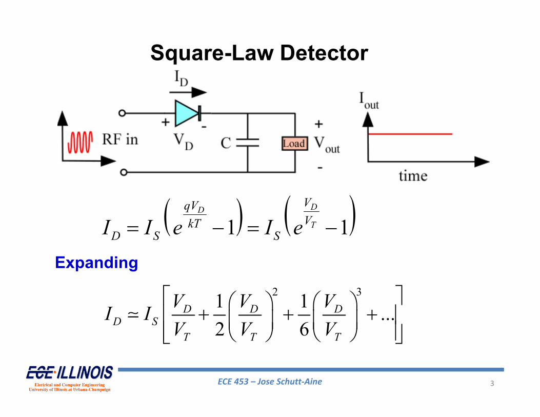
In order to operate properly, diode current must remain in the square-law region
• Detector will receive RF at input and will produce a DC voltage proportional to the magnitude of the RF input
ECE 453 – Jose Schutt‐Aine 3
Square-Law Detector
Expanding
1 1DD
T
VqVVkT
D S SI I e I e
2 31 1 ...2 6
D D D
D ST T T
V V VI IV V V

ECE 453 – Jose Schutt‐Aine 4
Square-Law Detector
If VD is small2 31 1 ...
2 6
D D DD S
T T T
V V VI IV V V
Iout = aVD where a is some constant
If VD is larger2 31 1 ...
2 6
D D DD S
T T T
V V VI IV V V
Iout = bVD2 where b
is some constant
If VD is even larger2 31 1 ...
2 6
D D DD S
T T T
V V VI IV V V
Iout = cVD3 where c is
some constant

ECE 453 – Jose Schutt‐Aine 5
Square-Law Detector
GOAL: Keep detector operating in square-law range. Then, Iout is proportional to VD
2 and thus proportional to the power input.
ECE 453 – Jose Schutt‐Aine 6
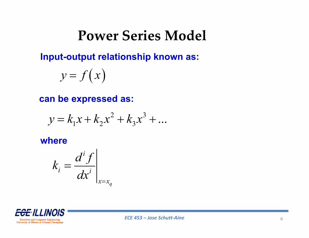
Power Series Model
y f x
2 31 2 3 ...y k x k x k x
q
i
i ix x
d fkdx
Input-output relationship known as:
can be expressed as:
where
ECE 453 – Jose Schutt‐Aine 7
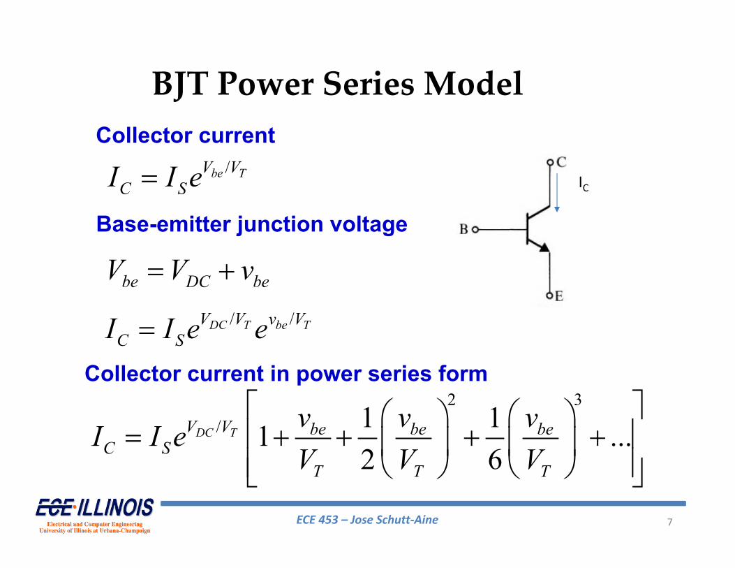
BJT Power Series Model
/be TV VC SI I e
be DC beV V v / /DC T be TV V v V
C SI I e e
2 3/ 1 11 ...
2 6DC TV V be be be
C ST T T
v v vI I eV V V
IC
Collector current
Base-emitter junction voltage
Collector current in power series form

ECE 453 – Jose Schutt‐Aine 8
Power Series Model for MOSFET
22
D n ox GS TWI C V VL
2 222D n ox GS GS T TWI C V V V VL
No third order or higher terms idealized square-law characteristic
IDMOSFET drain current current

ECE 453 – Jose Schutt‐Aine 9
Distortion and Nonlinearities
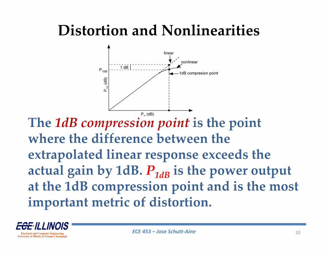
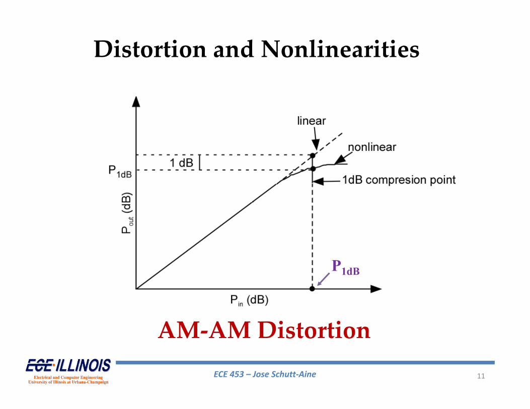
Distortion occurs when the output signal from an amplifier approaches the extremes of the load line and the output is no longer an exact replica of the input.The ideal amplifier follows a linear relationship. Distortion leads to a deviation from this linear relationship
ECE 453 – Jose Schutt‐Aine 10
The 1dB compression point is the point where the difference between the extrapolated linear response exceeds the actual gain by 1dB. P1dB is the power output at the 1dB compression point and is the most important metric of distortion.
Distortion and Nonlinearities
ECE 453 – Jose Schutt‐Aine 11
Distortion and Nonlinearities
AM‐AM Distortion
P1dB

ECE 453 – Jose Schutt‐Aine 12
AM‐PM Distortion
Distortion and Nonlinearities
ECE 453 – Jose Schutt‐Aine 13
AM‐AM distortion is generally more significant
Distortion is a result of nonlinearities in the response of an amplifier. One possible model for the response is:
2 3 ...out in in inV aV bV cV
When the input signal is large enough the higher order terms become significant
Distortion and Nonlinearities
ECE 453 – Jose Schutt‐Aine 14
If the input is a sine wave, the output will contain harmonics of the input. That is the output will have frequency components that are integer multiples of the fundamental (CW) sine wave input signalWhen the input signal is a two‐tone signal (modulated signal), additional tones will appear at the output and we say that the distortion produces intermodulation products (IMP)
Distortion and Nonlinearities
ECE 453 – Jose Schutt‐Aine 15
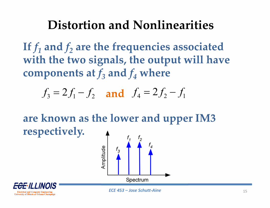
If f1 and f2 are the frequencies associated with the two signals, the output will have components at f3 and f4where
3 1 22f f f and 4 2 12f f f
are known as the lower and upper IM3 respectively.
Distortion and Nonlinearities
ECE 453 – Jose Schutt‐Aine 16
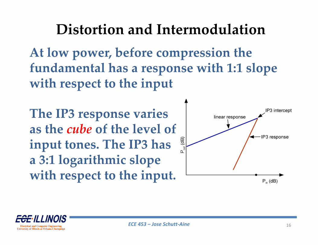
At low power, before compression the fundamental has a response with 1:1 slope with respect to the input
The IP3 response varies as the cube of the level of input tones. The IP3 has a 3:1 logarithmic slope with respect to the input.
Distortion and Intermodulation
ECE 453 – Jose Schutt‐Aine 17
The point of intersection of the extrapolated linear output (of power Po) and third order (IP3) of power PIP3 is called the third‐order intercept point which is a key parameter
• Harmonics can be filtered out by filters• Intermodulation distortion cannot be filtered out because they are in the main passband
Distortion and Intermodulation

ECE 453 – Jose Schutt‐Aine 18
Distortion and Intermodulation
ECE 453 – Jose Schutt‐Aine 19
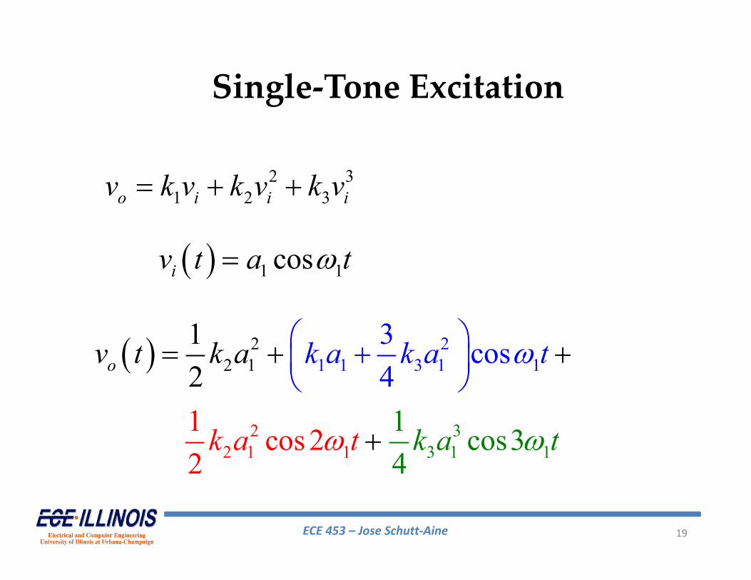
Single‐Tone Excitation
2 31 2 3o i i iv k v k v k v
1 1cosiv t a t
22 1
22 1 1
3
21
3 1
1
1
1 3 1
1 c
3 cos4
os31 cos22
12
4
o k a k a tv
k a t
t k
k a t
a
ECE 453 – Jose Schutt‐Aine 20
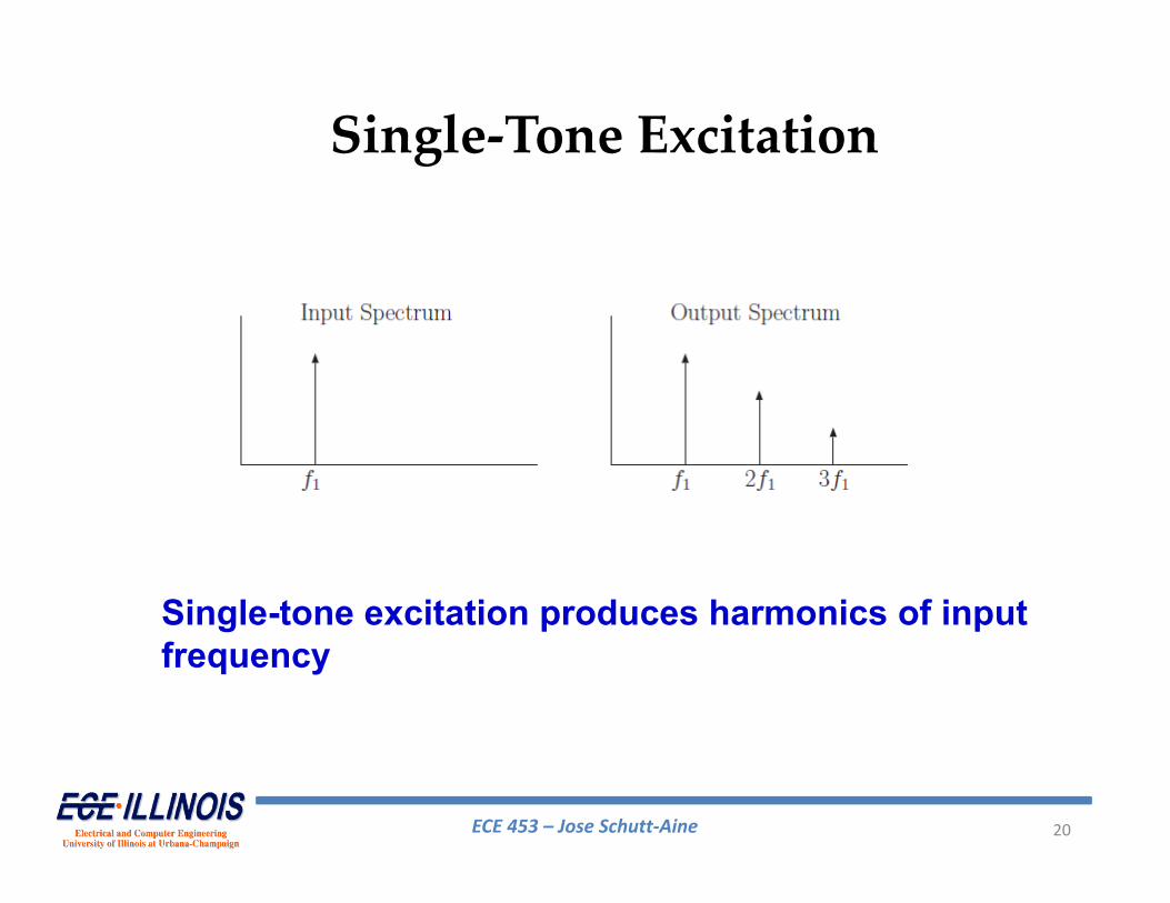
Single‐Tone Excitation
Single-tone excitation produces harmonics of input frequency
ECE 453 – Jose Schutt‐Aine 21
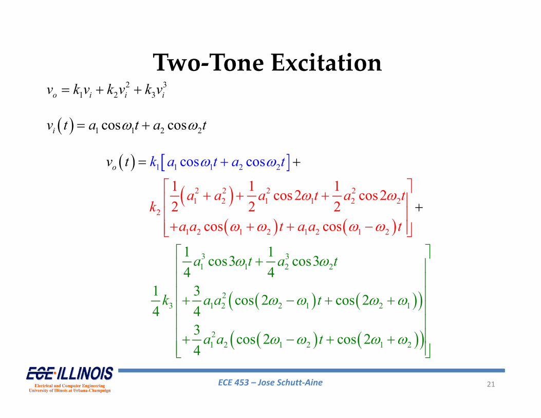
Two‐Tone Excitation2 3
1 2 3o i i iv k v k v k v
1 1 2 2cos cosiv t a t a t
2 2 2 21 2 1 1 2 2
1 1
3 31 1 2 2
23 1 2 2 1 2 1
21 2
1 2 2
2
1 2
1 2 1
2 1
2
1 2 1 2
1 1cos3 cos34 4
1
1 1
3 cos 2
1cos2 cos
co
cos 24 4
3 cos 2 cos 24
22 2 2
cos cos
s coso
a t a t
k a a t
a a t
a a a t a tk
a a t a a t
k a t at tv

ECE 453 – Jose Schutt‐Aine 22
Two-tone excitation produces intermodulation
Two‐Tone Excitation

ECE 453 – Jose Schutt‐Aine 23
Intermodulation Ratio (IMR)
2
( )inIMi
d I
PPIMRP P
inP input power of fundamental componentsdP
IMP output power of in‐band 3rd – order intermodulation( )iIP third‐order intercept
output power of fundamental components
( )( ) 2 ( ) 2 ( )iin IIMR dB P dBm P dBm
In dB:
( )iIP

ECE 453 – Jose Schutt‐Aine 24
Dynamic Range of Receiving System
Maximum useable input signal power levelDRMinimum useable input signal power level
Dynamic range is defined as:
Pmin input power for specified SNRo,min (MDS)
Pmax two‐tone input power (per tone) at which SNR of in‐band 3rd order IM product = SNRo,min at system output
Can show that ( )min
23
iIDR P P
( )iIP is the third‐order intercept
ECE 453 – Jose Schutt‐Aine 25
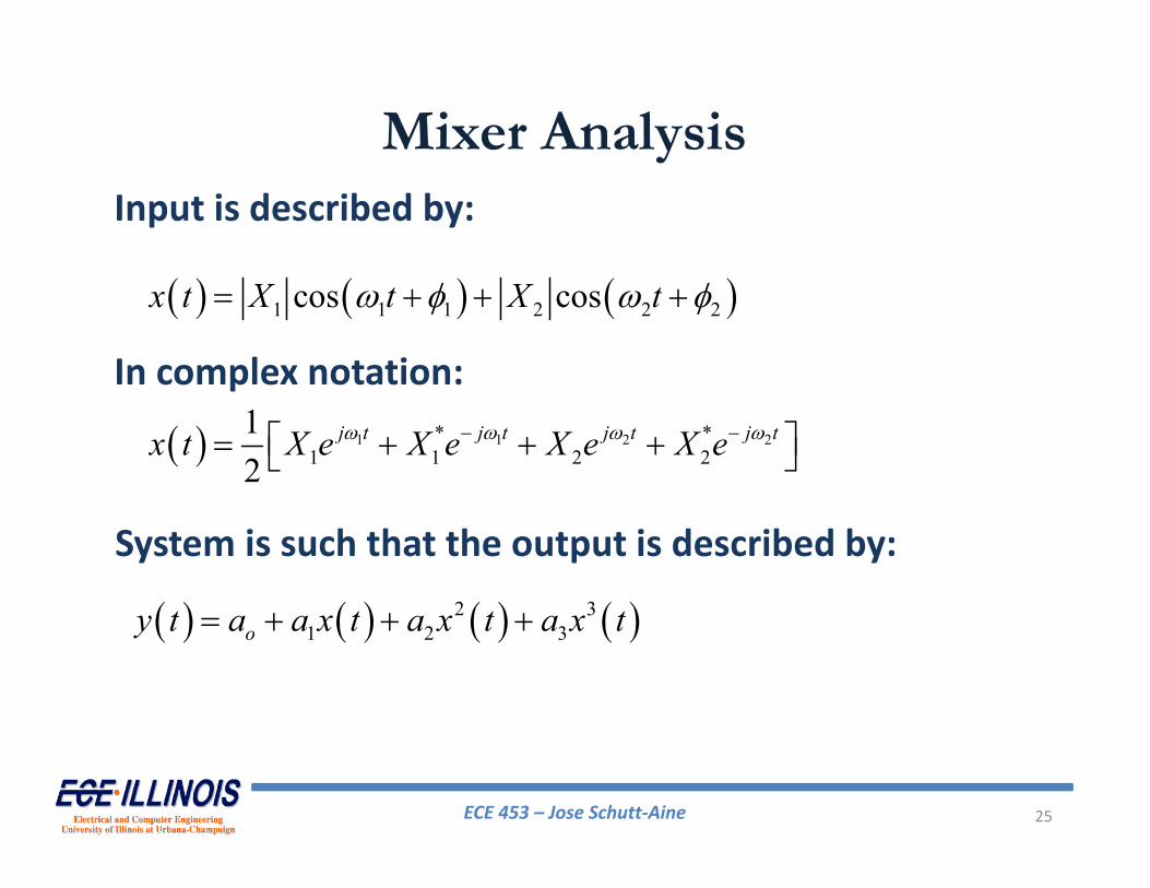
1 1 1 2 2 2cos cosx t X t X t
1 1 2 2* *1 1 2 2
12
j t j t j t j tx t X e X e X e X e
2 31 2 3oy t a a x t a x t a x t
Mixer AnalysisInput is described by:
In complex notation:
System is such that the output is described by:

ECE 453 – Jose Schutt‐Aine 26
Intermodulation ProductsIntermodulation Product Frequency Order
½(X1X1*)½(X2X2*)
00
22
2½X1= X12(½)33X1
2X1*= ¾X12X1*
2(½)36X1X2X2*= 3(½)X1X2X2*
111
133
2½X2= X22(½)33X2
2X2*= ¾X22X2*
2(½)36X2X1X1*= 3(½)X2X1X1*
222
133
2(½)2X12= ½ X1
2 21 22(½)2X2
2= ½ X22 22 2
2(½)3X12= ¼ X1
3 31 32(½)3X2
2= ¼ X23 32 3
2(½)X1X2= X1X2 1 + 2 22(½)X1X2*= X1X2* 1 ‐ 2 2
2(½)33X12X2= ¾ X1
2X2 21 + 2 32(½)33X1
2X2*= ¾ X12 X2* 21 ‐ 2 3
2(½)33X22X1= ¾ X2
2X1 1 + 22 32(½)33X2
2X1*= ¾ X22 X1* ‐ 22 3

ECE 453 – Jose Schutt‐Aine 27
A linear causal system with memory can be described by the convolution representation
( )y t h x t d
where x(t) is the input, y(t) is the output, and h(t) the impulse response of the system.
A nonlinear system without memory can be described with a Taylor series as:
1
( ) ( ) nnn
y t a x t
where x(t) is the input and y(t) is the output. The an are Taylor series coefficients.
Volterra Series

ECE 453 – Jose Schutt‐Aine 28
A Volterra series combines the above two representations to describe a nonlinear system with memory
1 111
1( ) ... ,..., ( )!
n
n n n rrn
y t du du g u u x t un
1 2 2 1
1 1 1
2 1 2
1 2 3 3 1 2 3 1 2 2 1 2 1 2 3
1( 1 ( ) (
1 ( , ) ( ) ( )2
)
!
1 ( , , ) ( ) ( ) ( , ) ( ) ( ) ( )2!.
!
.
)1
.
du du g u u x t u x t u
du du du g u u u x t u x t u g u u x t u x
du g u x ty
t u x t
t u
u
where x(t) is the input and y(t) is the output and the gn(u1,…,un) are called the Volterra kernels
impulse response
higher-order impulse responses
Volterra Series


![[3.4]_Fiber Nonlinearities](https://static.documents.pub/doc/80x56/55cf8e81550346703b92da6f/34fiber-nonlinearities.jpg)


