ECE236A Semiconductor Heterostructure Materials Crystal Growth and Material Aspects of Heterostructures: Lecture 4 Oct. 7, 2019 • Introduction to growth techniques (LPE, VPE, MBE, OMVPE, CBE) • Thermodynamic analysis: - Driving force for growth, supersaturation, growth rate - Dopant incorporation, surface reconstruction, Langmuir isotherm for adsorption. • Kinetic analysis: - Reaction rates - Homogeneous/heterogeneous pyrolysis - Simultaneous pyrolysis of cation and anion sources 1 Ref.: Organometallic Vapor Phase Epitaxy, Theory and Practice Gerald B. Stringfellow, 2 nd Ed. 1999.
Transcript
ECE236A Semiconductor Heterostructure MaterialsCrystal Growth and Material Aspects of
Heterostructures:Lecture 4 Oct. 7, 2019
• Introduction to growth techniques (LPE, VPE, MBE, OMVPE, CBE)
• Thermodynamic analysis:- Driving force for growth, supersaturation, growth rate- Dopant incorporation, surface reconstruction, Langmuir isotherm for
adsorption.
• Kinetic analysis:- Reaction rates- Homogeneous/heterogeneous pyrolysis- Simultaneous pyrolysis of cation and anion sources
1Ref.: Organometallic Vapor Phase Epitaxy, Theory and PracticeGerald B. Stringfellow, 2nd Ed. 1999.
Thin Film Growth
• Oh, its your standard boy meets girl, boy loses girl, boy invents a new deposition technique for ultra-thin film semiconductors, boy gets girl back story.
after unknown 2
How are thin-film deposition techniques invented?
Liquid Phase Epitaxy• One of the oldest techniques for the growth of III/V and II/VI semiconductors. • Extremely simple apparatus, low impurity and point defect levels.
Ga rich supersaturated state
• Growth of GaAs from Ga-rich melts reduces Ga vacancies or As antisites (EL2) which can act as deep electron trap levels.
• Distribution coefficients of impurities are small such that very little impurities get incorporated into the film.
• For example, oxygen has low distribution coefficient in AlGaAs and Al2O3 segregates to the liquid surface providing high purity AlGaAs by LPE.
• While excellent for growing thick layers and simple junctions, scalability and growth of abrupt composition heterostructures is difficult with LPE. 3
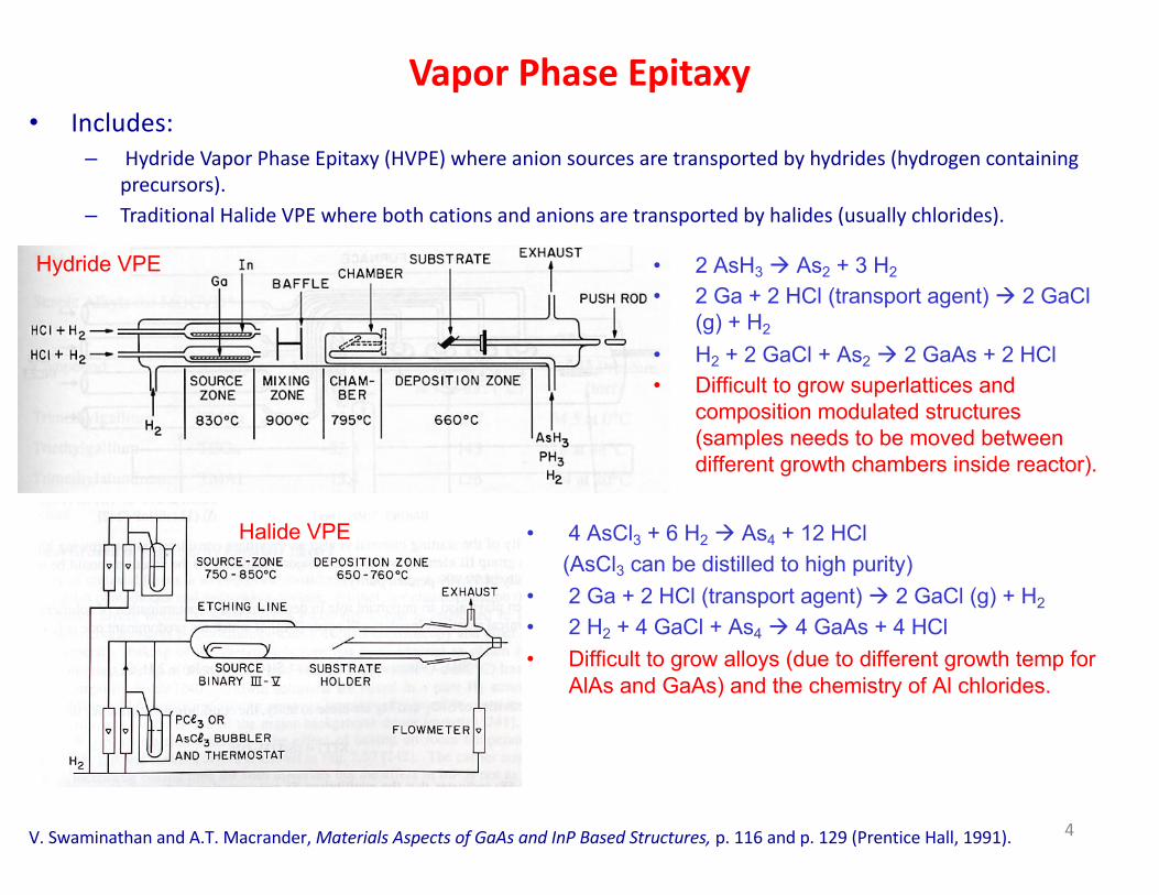
Vapor Phase Epitaxy• Includes:
– Hydride Vapor Phase Epitaxy (HVPE) where anion sources are transported by hydrides (hydrogen containing precursors).
– Traditional Halide VPE where both cations and anions are transported by halides (usually chlorides).
V. Swaminathan and A.T. Macrander, Materials Aspects of GaAs and InP Based Structures, p. 116 and p. 129 (Prentice Hall, 1991).
• 4 AsCl3 + 6 H2 à As4 + 12 HCl(AsCl3 can be distilled to high purity)
• 2 Ga + 2 HCl (transport agent) à 2 GaCl (g) + H2
• 2 H2 + 4 GaCl + As4 à 4 GaAs + 4 HCl• Difficult to grow alloys (due to different growth temp for
AlAs and GaAs) and the chemistry of Al chlorides.
• 2 AsH3 à As2 + 3 H2
• 2 Ga + 2 HCl (transport agent) à 2 GaCl(g) + H2
• H2 + 2 GaCl + As2 à 2 GaAs + 2 HCl• Difficult to grow superlattices and
composition modulated structures (samples needs to be moved between different growth chambers inside reactor).
4
Hydride VPE
Halide VPE
Molecular Beam Epitaxy• MBE is the growth system responsible for the revolution in device physics due to superlattice
growth capability.• Simple whereby elemental sources are evaporated at a controlled rate on a heated substrate
under ultrahigh-vacuum conditions.
• The expenses to maintain UHV are high. Replenishing the source material requires breaking the vacuum followed by baking out the system (usually 2 weeks procedure); reproducibility becomes an issue.
• Morphological defects due to cation sources are hard to eliminate.• Growing phosphorous compounds is hard, whereby it collects in pumps and is pyrophoric.• Growth of volatile N compounds (AlGaInN) is hard.
Chemical Beam Epitaxy (CBE)• Is a hybrid of OMVPE and MBE. • Known also as Organometallic MBE (OMMBE) or metal-organic MBE (MOMBE)
• Sources include organometallic group V or elemental group III sources, and hydride group V or elemental group V, all injected into a UHV system.
After W.T.Tsang
MOVPE MOMBE
7
Comparison between Epitaxy Techniques
8
Key Process in OMVPE
9
Thermodynamics (1)• Applied to epitaxy, we want to define the relationship between the compositions of the
various phases in an equilibrium system at constant temperature, T, and pressure, P.
Energy available to do useful workG =H−TS
system enthalpy
system entropy (disorder)
H =E +PV
Internal energy
volume
• For a 2-phase, α and β, system, the total free energy is: G' =Gα' +G
β'
∂G'
∂ni
"
#$$
%
&''T ,P ,ni
α
−∂G'
∂ni
"
#$$
%
&''T ,P ,ni
β
=0
• The change in G’ for an infinitely small number dni is negligible, therefore:
Chemical potential: µiα µi
β
Fixed P,T: dG =dH−TdS =0Expand H and G to get:
dH =dE +PdV +VdPdG =VdP−SdT
⇒µiα =µi
β
dG' =V 'dP−S 'dT
PV ' =nRT⇒V ' =nRTP
dG' =nRT dPP=nRTd lnP( )for a change in pressure, 10
Ideal gas law:
• Equilibrium is defined as the state where the Gibbs Free energy per mole, G, is a minimum.
Thermodynamics (2)
⇒µ =RT lnP
activity coefficient
dG' =nRT dPP=nRTd lnP( )
µ =µ0 +RT ln PP0
With respect to a reference state with chemical potential and pressure : µ0 P0
And for a gas mixture with component i:
µi =µi0 +RT ln Pi
Pi0
Pi is the partial pressure: where xi is the molar fraction of component i.Pi = xiP
These equations apply for an ideal gas. For a non-ideal gas, xi is replaced by ai, the activity.
µi =µi0 +RT lnai =µi0 +RT lnxiγ i
11
!" = $"%" Υi, the activity coefficient.
Thermodynamic Driving Force for Epitaxial Growth
A⇔BFor the simple process:k1
k−1
The equilibrium condition is: µA0 +RT lnaAe =µB0 +RT lnaBe
aAe is the activity at equilibrium.
aBe
aAe=exp
− µB0 −µA
0( )RT
"
#
$$
%
&
''=K1 =
k1k−1
Equilibrium constant
Basic law of mass action
Δµ = µB −µA
Δµ = µB0 + RT lnaB −µA
0 − RT lnaA
Δµ = RT ln aAe aBaAaB
e
#
$%
&
'(
When the system is not in equilibrium, the thermodynamic driving force to restore equilibrium is:
A non-equilibrium is created in order to drive the growth. This energy is referred to as ‘supersaturation’ (deviation from equilibrium state). The only limiting factor for the growth becomes mass transport as we will see next.
12
Equilibrium at the Vapor-Solid Interface
Δµ * is the chemical potential of the input gas phase.
ΔµD is the chemical potential required to diffuse the reactants to the growth interface (mass transport).
is the chemical potential required for surface reactions (kinetic process).
ΔµS
Near equilibrium at growth interface:fast reaction kinetics and mass-transport limited.
ΔµD
mass-transportlimited regime
Kinetically-limitedregime
Thermodynamically limited regime
13
Growth Rate
ΔµD
In the mass transport limited regime, the interfacial partial pressure nearly satisfy the equilibrium:
aGaAs
pGai pAs4
i( )1/4 =KGaAs
The input pressure is highly supersaturated:
pGa* pAs
*
pGai
pAsi
pGa* pAs4
*( )1/4>> pGa
i pAs4i( )
1/4or Δµ * >>0
pGa* <<4pAs4
*Usually, or the input V/III ratio is much greater than 1.
This means that Ga is nearly depleted at the growth interface pGai << pGa
*
while the As4 partial pressure is hardly diminished. pAs4i ≈ pAs4
*
δ0
Assume input reactants need to diffuse through a boundary layer of thickness δ0The flux can be expressed as:
J =DGa pGa
* −pGai( )
RTδ0DGa is the diffusion coefficient of Ga (in any molecular form) through the boundary layer.The growth rate proportional the input Ga partial pressure as verified experimentally. 14
15Dayeh & Picraux in “Silicon and Silicide Nanowires: Applications, Fabrication, and Properties”, Edited by Yu Huang and King-Ning Tu(2014) Pan Stanford Publishing Pte. Ltd.
R1
R2
R3
µv
µl
µs
Layer propagation & growth
3)
Triple phase boundary
Supersaturation & nucleation
2)
GeH4
Ge (111)
R1
R2
R3
Au-Ge (L)
Ge (111)
0.0 0.2 0.4 0.6 0.8 1.0
200
400
600
800
1000
1200
Tem
pera
ture
(0 C)
Composition
Au
Liquid
solidsolidTm ~ 360C
Ge
(Ge)
Cin
CeqΔμ
16
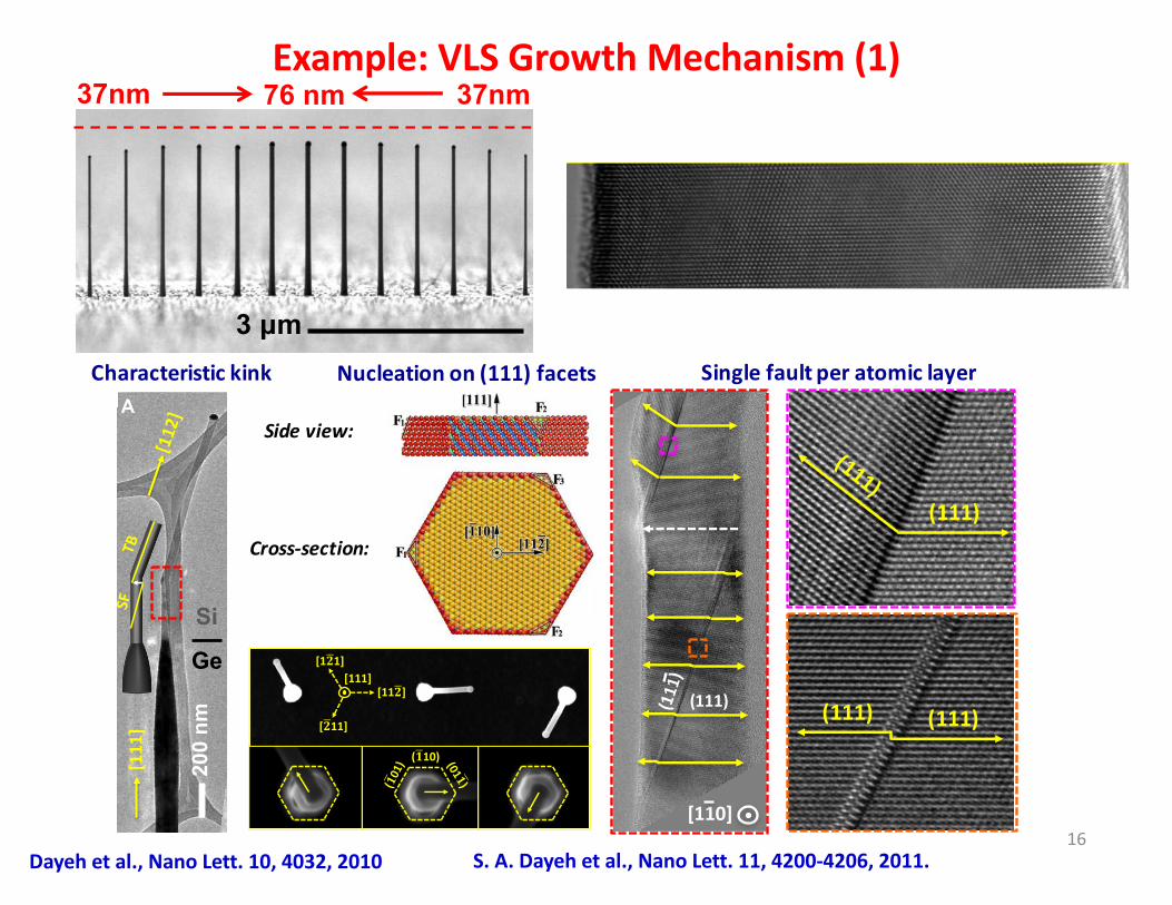
Example: VLS Growth Mechanism (1)37nm 76 nm 37nm
3 μm
A
200
nm
Si
Ge
[111
]$[112]$
Characteristickink
( 10)
[11 ]
[1 1]
[ 11]
[111]
SinglefaultperatomiclayerNucleationon(111)facets
(111) (111)
(111)
(111)
[110]
Sideview:
Cross-section:
S. A. Dayeh et al., Nano Lett. 11, 4200-4206, 2011.Dayeh et al., Nano Lett. 10, 4032, 2010
17
Example: VLS Growth Mechanism (2)
0.0 0.2 0.4 0.6 0.8 1.0
0.2
0.4
0.6
0.8
1.0
ΔΔµµ/
KT
Cin- C0(NW)
0.2
0.4
0.6
0.8
1.0
v/b
Pin- P0(NW)
T1 T2 < T1 T3 > T1 0 10 20 30 40 50 60 70 800
2
4
6
8
10
12
406 C
366 C
v/b
d (nm)
267 C
10 20 30 40 50
0.45
0.50
0.55
0.60
0.65
0.70 406 C
366 C
v1/2 (x
10-3 c
m1/
2 /s1/
2 )
1/d (x104 cm-1)
267 C
a)# b)#
Take into account only thermodynamics (normalize to kinetics, b).
10 20 30 40 50 60 70 80 900.1
0.2
0.3
0.4
0.5
0.6
0.7
0.8
Pi=0.18 Torr
Pi=0.3 Torr
Pi=0.6 Torr
v1/2 (x
103 c
m1/
2 /s1/
2 )
1/d (x104 cm-1)
0 10 20 30 40 50 60 700.0
0.5
1.0
1.5
2.0
2.5 Pi=0.6 Torr
Pi=0.3 Torr
Pi=0.18 TorrL
(µµm
)
d (nm)
a)# b)#
Influence of input partial pressure in experiment.
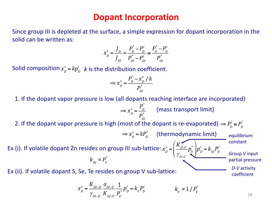
Dopant IncorporationSince group III is depleted at the surface, a simple expression for dopant incorporation in the solid can be written as:
xDs =
JDJIII
=PD* −PD
i
PIII* −PIII
i≅PD* −PD
i
PIII*
xDs = kpD
iSolid composition k is the distribution coefficient.
⇒ xDs =
PD* − xD
s /kPIII*
1. If the dopant vapor pressure is low (all dopants reaching interface are incorporated)
⇒ xDs =
PD*
PIII*
2. If the dopant vapor pressure is high (most of the dopant is re-evaporated) ⇒ PDi ≅PD
*
⇒ xDs = kPD
*
(mass transport limit)
(thermodynamic limit)
xDs =
KD−V
γD−VpV*
"
#$$
%
&''pD
i = kIIIPDiEx (i). If volatile dopant Zn resides on group III sub-lattice:
Ex (ii). If volatile dopant S, Se, Te resides on group V sub-lattice:
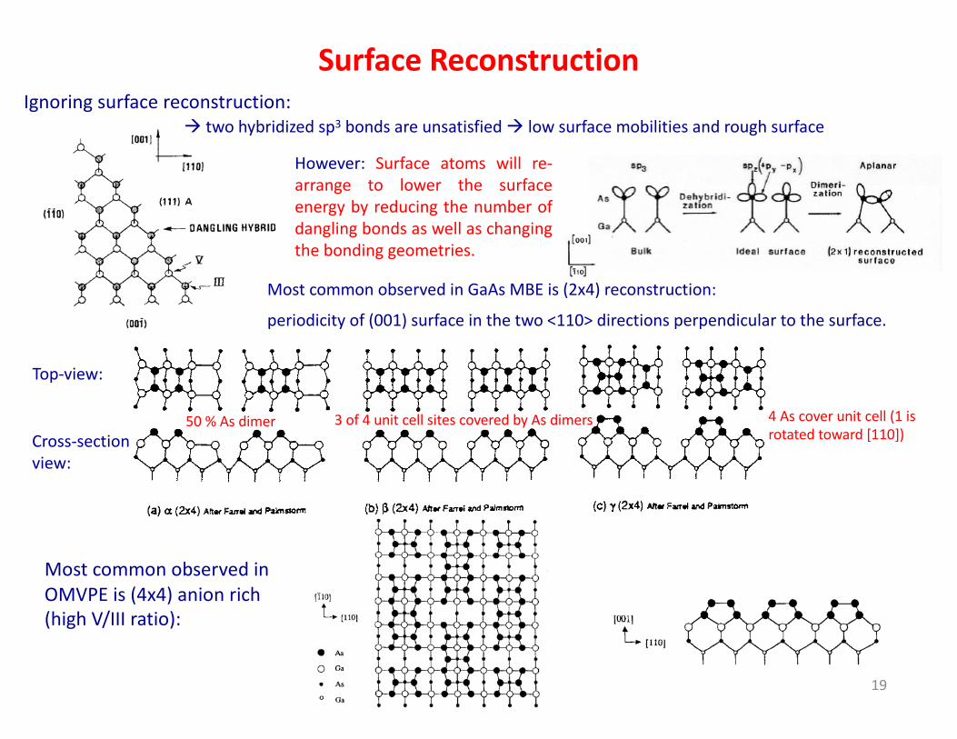
à two hybridized sp3 bonds are unsatisfied à low surface mobilities and rough surface
However: Surface atoms will re-arrange to lower the surfaceenergy by reducing the number ofdangling bonds as well as changingthe bonding geometries.
Most common observed in GaAs MBE is (2x4) reconstruction:
periodicity of (001) surface in the two <110> directions perpendicular to the surface.
50 % As dimer 4 As cover unit cell (1 is rotated toward [110])
3 of 4 unit cell sites covered by As dimers
Top-view:
Cross-section view:
Most common observed in OMVPE is (4x4) anion rich (high V/III ratio):
19
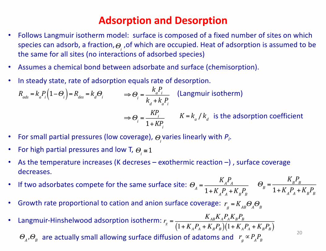
Adsorption and Desorption• Follows Langmuir isotherm model: surface is composed of a fixed number of sites on which
species can adsorb, a fraction, ,of which are occupied. Heat of adsorption is assumed to be the same for all sites (no interactions of adsorbed species)
Θi
• Assumes a chemical bond between adsorbate and surface (chemisorption).
• In steady state, rate of adsorption equals rate of desorption. Rads = kaPi 1−Θi( )=Rdes = kdΘi ⇒Θi =
kaPikd +kaPi
(Langmuir isotherm)
⇒Θi =KPi
1+KPiK = ka /kd is the adsorption coefficient
• For small partial pressures (low coverage), varies linearly with Pi.Θi
• For high partial pressures and low T, Θi ≅1• As the temperature increases (K decreses – exothermic reaction –) , surface coverage
decreases.• If two adsorbates compete for the same surface site: ΘA =
KAPA1+KAPA +KBPB
ΘB =KBPB
1+KAPA +KBPB• Growth rate proportional to cation and anion surface coverage: rg =KABΘAΘB
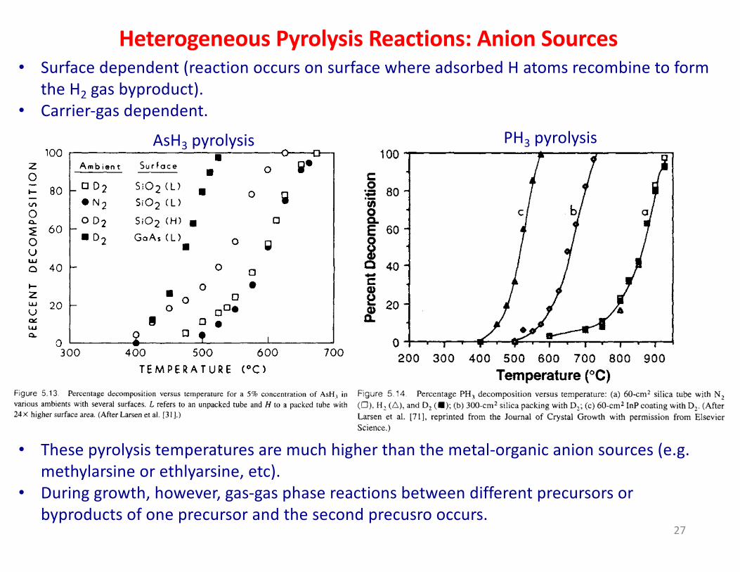
Heterogeneous Pyrolysis Reactions: Anion Sources• Surface dependent (reaction occurs on surface where adsorbed H atoms recombine to form
the H2 gas byproduct).• Carrier-gas dependent.
AsH3 pyrolysis
• These pyrolysis temperatures are much higher than the metal-organic anion sources (e.g. methylarsine or ethlyarsine, etc).
• During growth, however, gas-gas phase reactions between different precursors or byproducts of one precursor and the second precusro occurs.
PH3 pyrolysis
27
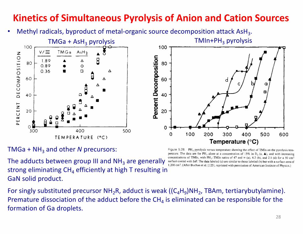
Kinetics of Simultaneous Pyrolysis of Anion and Cation Sources• Methyl radicals, byproduct of metal-organic source decomposition attack AsH3.
TMGa + AsH3 pyrolysis
TMGa + NH3 and other N precursors:The adducts between group III and NH3 are generally strong eliminating CH4 efficiently at high T resulting in GaN solid product.For singly substituted precursor NH2R, adduct is weak ((C4H9)NH2, TBAm, tertiarybutylamine). Premature dissociation of the adduct before the CH4 is eliminated can be responsible for the formation of Ga droplets.