1 1 ECET 211 Electric Machines & Controls Lecture 3-1 (Part 1 of 2) Motor Transformers and Distribution Systems Text Book: Electric Motors and Control Systems , by Frank D. Petruzella, published by McGraw Hill, 2015. Paul I-Hai Lin, Professor of Electrical and Computer P.E. States of Indiana & California Dept. of Computer, Electrical and Information Technology Purdue University Fort Wayne Campus Prof. Paul Lin Lecture 3 Motor Transformers and Distribution Systems Chapter 3. Motor Transformers and Distribution Systems • Part 1. Power Distribution • Part 2. Transformer Principles • Part 3. Transformer Connections and Systems Prof. Paul Lin 2
Transcript
1
1
ECET 211 Electric Machines & Controls
Lecture 3-1 (Part 1 of 2)
Motor Transformers and Distribution Systems
Text Book: Electric Motors and Control Systems, by Frank D.
Petruzella, published by McGraw Hill, 2015.
Paul I-Hai Lin, Professor of Electrical and Computer
P.E. States of Indiana & California
Dept. of Computer, Electrical and Information Technology
Purdue University Fort Wayne Campus
Prof. Paul Lin
Lecture 3 Motor Transformers and Distribution
Systems Chapter 3. Motor Transformers and Distribution Systems
• Part 1. Power Distribution
• Part 2. Transformer Principles
• Part 3. Transformer Connections and Systems
Prof. Paul Lin 2
2
Lecture 3 Motor Transformers and Distribution
Systems Part 1. Power Distribution
Transformers
• Electrical apparatus that transfer electrical energy from one
electrical circuit to another by magnetic coupling
• Transfer electricity from one electric circuit to another by means
of electromagnetic mutual induction
• Roles that transformers play in motor power distribution and
control systems
• The purpose: converts AC power at voltage level to AC power of
the same frequency at another voltage level
Distribution System
• Refers to the manner in which electrical energy is transmitted
from the generators to its many point of use
Prof. Paul Lin 3
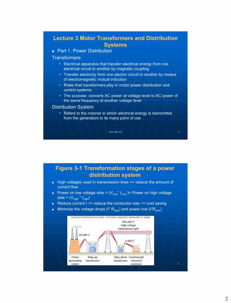
Figure 3-1 Transformation stages of a power
distribution system
High voltages used in transmission lines => reduce the amount of
current flow
Power on low voltage side = (VLow* ILow )= Power on high voltage
side = (Vhigh * Ihigh)
Reduce current I => reduce the conductor size => cost saving
Minimize the voltage drops (I* Rwire) and power lost (I2Rwire)
Prof. Paul Lin 4
3
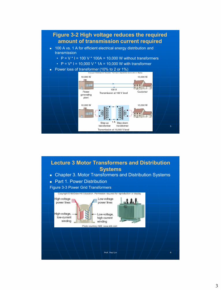
Figure 3-2 High voltage reduces the required
amount of transmission current required
100 A vs. 1 A for efficient electrical energy distribution and
transmission
• P = V * I = 100 V * 100A = 10,000 W without transformers
• P = V* I = 10,000 V * 1A = 10,000 W with transformer
Power loss of transformer (10% to 2 or 1%)
Prof. Paul Lin 5
Lecture 3 Motor Transformers and Distribution
Systems Chapter 3. Motor Transformers and Distribution Systems
Part 1. Power Distribution
Figure 3-3 Power Grid Transformers
Prof. Paul Lin 6
4
Lecture 3 Motor Transformers and Distribution
Systems A power substation consists of equipment installed for switching,
changing or regulating line voltage
Figure 3-4 Factory assembled unit substation
Figure 3-5 Single-line diagram for a typical unit
substation: High-voltage primary switchgear,
Transformer section, Low-voltage distribution
section
Prof. Paul Lin 7
Distribution Systems
Used to distribute power throughout large commercial and industrial
facilities.
Power must be distributed through various switchgears, transformers,
and panelboards.
Figure 3-6 Typical commercial/industrial distribution systemProf. Paul Lin 8
5
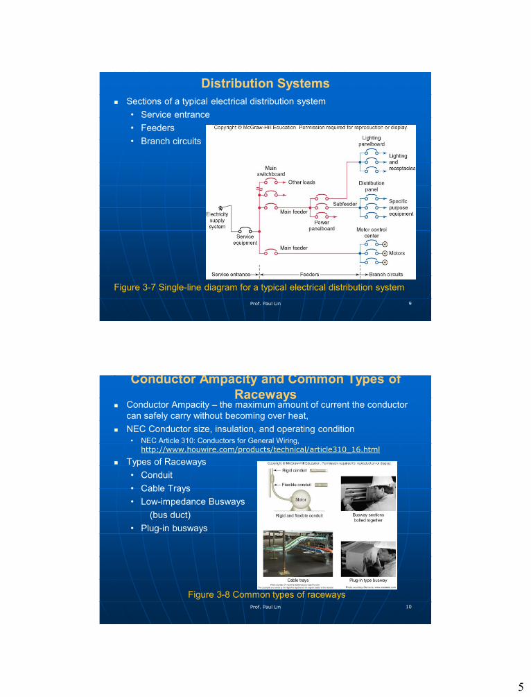
Distribution Systems
Sections of a typical electrical distribution system
• Service entrance
• Feeders
• Branch circuits
Figure 3-7 Single-line diagram for a typical electrical distribution system
Prof. Paul Lin 9
Conductor Ampacity and Common Types of
Raceways Conductor Ampacity – the maximum amount of current the conductor
can safely carry without becoming over heat,
NEC Conductor size, insulation, and operating condition