24


ECON VENTURI VALVECONSTANT VOLUME(CV) BINARY STATE(BV)/VARIABLE VOLUME(VV)
Operating and Instruction Manual

Venturi Type ValveEC
ON
VEN
TUR
I VA
LVE
Ope
ratin
g an
d In
stru
ctio
n M
anua
l
ECON venturi type valve is pressure independent airflow terminal unit to control airflow accurately. Venturi type of valve is widely used in critical operation area to control fume cupboard face velocity and room pressure. The variable volume valve can maintain preset volume over a range of 150 to 750 Pa by internal spring cone structure to sense the pressure change across the valve.
ECON venturi valve is available in aluminum body with stainless steel components. When corrosion resistance required, special coating will be applied. ECON series have several standard sizes from 6 “ to 16” in diameter for single valve body. When more flow required than can be furnished through a single 16” valve, multiple valves can be paralleled to meet required additional flow. The venturi valve will control air flow for both supply and exhaust ducts based on air volume preset by fast actuator. This valve in its normal operating mode is pressure independent so that flow can always maintain constant volume.

CONTENTS
1.0 Valve Structure1.1 Design Features1.2 Volume Range1.3 Dimensions1.4 Air-Regenerated Noise1.5 Applications1.6 Order Instructions1.7 Installation1.8 Exhaust Venturi Valve and PSU / Relay Interface Unit1.9a Venturi Valve Actuator connections using cable kit1.9b Venturi Valve Actuator hard wired connections
2.0 Limitation of Warranty and Liability
1
2
1 2 3 4 5 81011121314
15

1
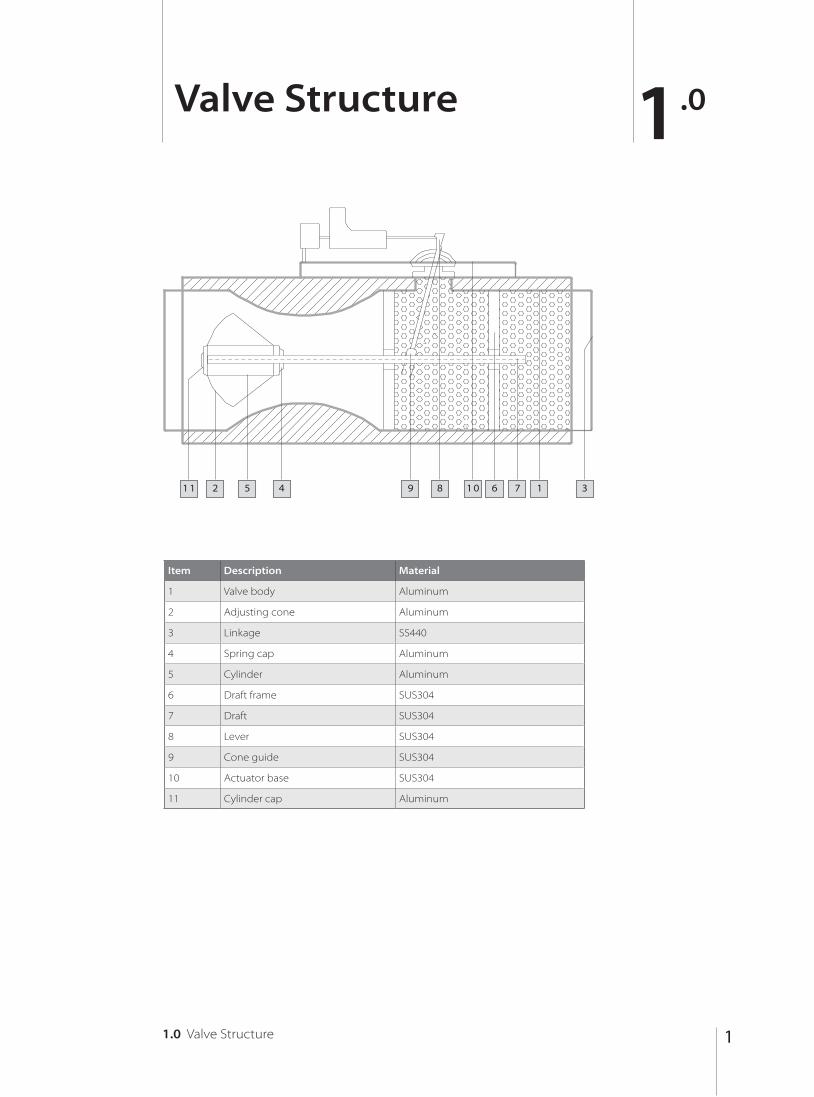
Valve Structure 1.0
1.0 Valve Structure
Item Description Material
1 Valve body Aluminum
2 Adjusting cone Aluminum
3 Linkage SS440
4 Spring cap Aluminum
5 Cylinder Aluminum
6 Draft frame SUS304
7 Draft SUS304
8 Lever SUS304
9 Cone guide SUS304
10 Actuator base SUS304
11 Cylinder cap Aluminum
1 1 2 5 4 9 8 1 0 6 7 1 3

2
Design Features 1.1
1.1 Design Features
ECON venturi valve incorporates a built – in sound attenuator. It is uniquely constructed of perforated aluminum with one-inch high quality fiberglass lined with special coating to resist erosion. The outside is covered with a 26 gauge galvanized steel jacket. The discharge and radiated noise levels are substantially reduced. The unit is completely thermally insulated.If required volume through valve is over single valve, multiple venturi valves can be paralleled to provide additional flow. The static pressure range is 150Pa to 750Pa. The material of valve body and cone are aluminum. The shaft is stainless and the bearing is Teflon or Heresite coated.
Special coating available if required.
ECON venturi valve can be controlled either by pneumatic or electric control system. No main air piping or consumption is required.
Standard Design Features:
· Fully pressure independent on range of 150 to 750 Pa· No main air consumption of pneumatic actuator· Factory set on range of whole designed volume· Fully insulated with 26g Galv. Cover· High accuracy of 5% on designed volume range· Less than 1 second response time· 16 points pre-calibrated in factory for VV valve· Compact design for easy installation
Optional Design Features:
· Hot water & electric booster coils· Dual duct systems· Multiple valve assemblies· Special coating provided for acid resistance· Pressure switch optional for fume cupboard alarm
Note :
3
1.2
c M
ult
iple
Val
ve C
V/B
V/V
VSH
UT-
OFF
TY
PE
SIZ
E o
f si
ng
le v
alve
No
. of
valv
esM
idd
le P
ress
ure
1
50
-75
0P
a (C
MH
)H
igh
Pre
ssu
re3
00
-12
50
Pa
(CM
H)
12”(
300m
m)
10-
1800
0-26
00
20-
3600
0-52
00
30-
5400
0-78
00
40-
7200
0-10
400
16”(
400m
m)
10-
3000
20-
6000
30-
9000
40-
1200
0
1.2
d P
ress
ure
Ind
epen
den
ce C
urv
e 340
510
680
1020
1700
750
62
5
5
00
375
25
0
1
25
0
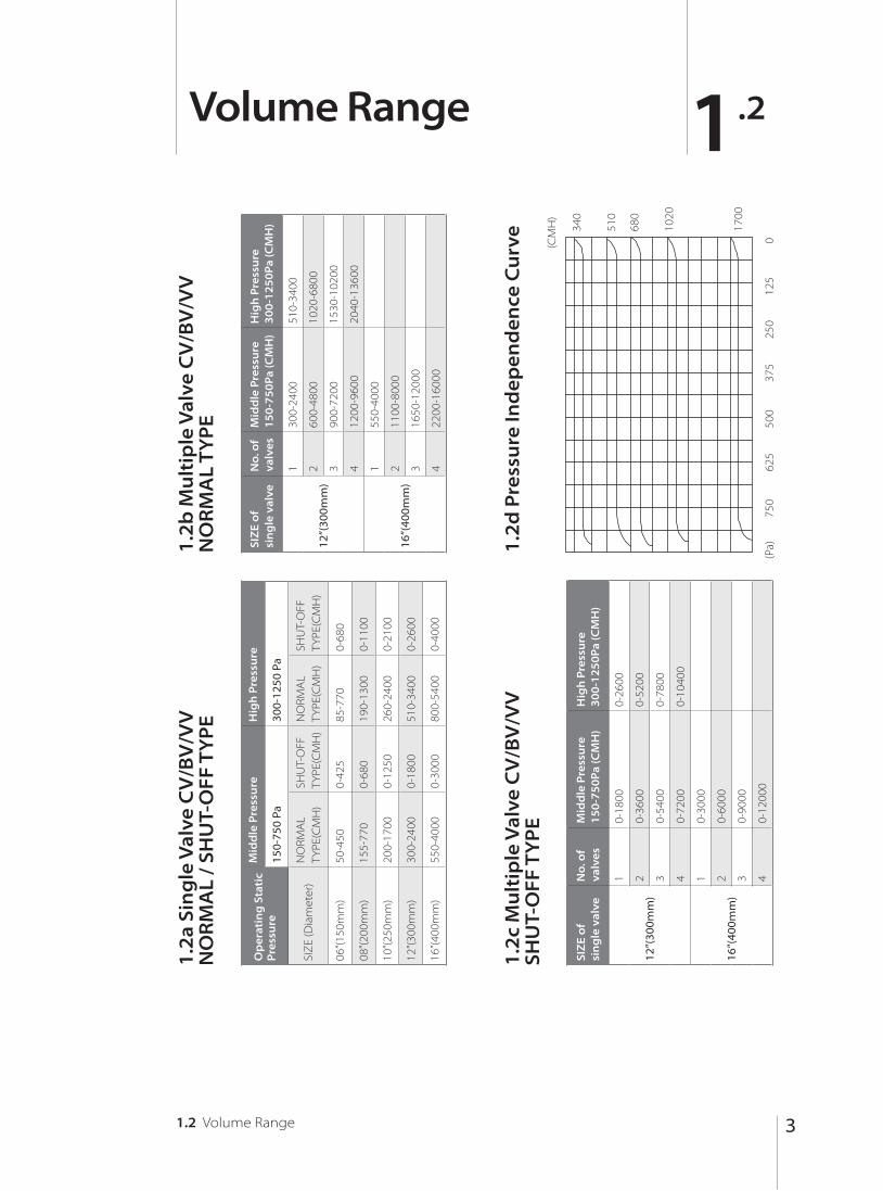
Volume Range 1.2
1.2 Volume Range
1.2
a Si
ng
le V
alve
CV
/BV
/VV
N
OR
MA
L /
SHU
T-O
FF T
YP
E O
per
atin
g S
tati
c P
ress
ure
Mid
dle
Pre
ssu
reH
igh
Pre
ssu
re
150-
750
Pa30
0-12
50 P
a
SIZ
E (D
iam
eter
)N
ORM
AL
TYPE
(CM
H)
SHU
T-O
FFTY
PE(C
MH
)N
ORM
AL
TYPE
(CM
H)
SHU
T-O
FFTY
PE(C
MH
)
06”(1
50m
m)
50-4
500-
425
85-7
700-
680
08”(2
00m
m)
155-
770
0-68
019
0-13
000-
1100
10”(2
50m
m)
200-
1700
0-12
5026
0-24
000-
2100
12”(3
00m
m)
300-
2400
0-18
0051
0-34
000-
2600
16”(4
00m
m)
550-
4000
0-30
0080
0-54
000-
4000
1.2
b M
ult
iple
Val
ve C
V/B
V/V
VN
OR
MA
L T
YP
E SI
ZE
of
sin
gle
val
veN
o. o
f va
lves
Mid
dle
Pre
ssu
re
15
0-7
50
Pa
(CM
H)
Hig
h P
ress
ure
30
0-1
25
0P
a (C
MH
)
12”(
300m
m)
130
0-24
0051
0-34
00
260
0-48
0010
20-6
800
390
0-72
0015
30-1
0200
412
00-9
600
2040
-136
00
16”(
400m
m)
155
0-40
00
211
00-8
000
316
50-1
2000
422
00-1
6000
(CM
H)
(Pa)

4
Dimensions 1.3
1.3 Dimensions
1.3a Single Valve CV/BV/VV NORMAL TYPE / SHUT-OFF TYPE
1.3b Multiple Valve CV/BV/VV NORMAL TYPE / SHUT-OFF TYPE
SIZE (Diameter)DIMENSIONS (mm)
I.D O.D L
06” (150mm) 150 200 560
08” (200mm) 200 250 630
10” (250mm) 250 300 680
12” (300mm) 300 350 680
16” (400mm) 400 450 920
SIZE of single valve
No. ofvalves
DIMENSIONS (mm)
W H L
12”(300mm)
1 350 350 680
2 740 370 840
3 1110 370 840
4 740 740 840
16”(400mm)
1 450 450 920
2 940 470 1080
3 1410 470 1080
4 940 940 1080
H
L W
H
LW
L
I.D O.D

5
Air-Regenerated Noise 1.4
1.4 Air-Regenerated Noise
Dis
char
ge
No
ise,
Sin
gle
Val
ve, N
orm
al T
ype
SIZ
E
(Dia
met
er)
100
Pa25
0 Pa
500
Pa75
0 Pa
VO
LUM
E
(CM
H)
OC
TAV
E B
AN
DO
CTA
VE
BA
ND
OC
TAV
E B
AN
DO
CTA
VE
BA
ND
23
45
67
NC
23
45
67
NC
23
45
67
NC
23
45
67
NC
6”
170
5838
3629
2527
<20
5545
4337
3234
<20
5952
5144
3941
<20
6359
5146
4823
255
5340
3832
2827
<20
5647
4540
3536
<20
6255
5346
4243
<20
6461
6153
4950
24
340
5542
4035
3131
<20
5749
4035
3131
<20
6558
5548
4545
<20
6563
6355
5252
27
425
5644
4238
3433
<20
5851
4238
3433
<20
6861
5740
4847
2070
6565
5755
5429
8”
510
5843
4238
3433
<20
6351
4238
3433
<20
6859
5752
4847
2072
6665
5855
5429
595
5945
4437
3228
<20
6453
4437
3228
<20
6961
5953
5149
2373
6867
6058
5631
680
6047
4639
3530
<20
6555
4639
3530
<20
7063
6255
5451
2574
7069
5859
5930
765
6146
4841
3832
<20
6657
4841
3832
2071
6564
5757
5329
7672
7164
6460
35
10”
765
6151
4739
3541
<20
6759
4739
3541
2072
6361
5151
5226
7670
6958
5959
30
1105
6352
4941
3843
<20
7059
5658
4749
2175
6563
5454
5427
7972
7161
6261
31
1445
6553
5144
4145
<20
7364
5864
5051
2278
6765
5757
5628
8274
7364
6563
32
1700
6655
5347
4447
<20
7663
6064
5353
2481
7967
6060
5830
8576
7567
6865
35
12”
1350
6051
4843
3936
<20
6958
5553
5048
<20
7365
6259
5957
2475
6965
6462
6328
1700
6455
5146
4239
<20
7160
5956
5150
2076
6965
6262
6025
7973
6967
6567
29
2040
6859
5449
4542
<20
7362
6359
5252
2179
7368
6565
6328
8377
7370
7871
31
2380
7062
5752
5745
<20
7564
6762
5354
2282
7671
6869
6630
8781
7773
7175
34
Va
riab
le v
olu
me
valv
e (V
V) t
ype
(10%
up
to
100
%)
No
te :

6 1.4 Air-Regenerated Noise
Rad
iate
d N
ois
e, S
ing
le V
alve
, No
rmal
Typ
e
SIZ
E
(Dia
met
er)
100
Pa25
0 Pa
500
Pa75
0 Pa
VO
LUM
E(C
MH
)O
CTA
VE
BA
ND
OC
TAV
E B
AN
DO
CTA
VE
BA
ND
OC
TAV
E B
AN
D
23
45
67
NC
23
45
67
NC
23
45
67
NC
23
45
67
NC
6”
170
4327
2221
1716
<20
4646
2722
2321
<20
5051
3228
2929
<20
5354
3533
3233
<20
255
4529
2524
2019
<20
4848
3025
2624
<20
5353
3531
3131
<20
5656
3836
3535
<20
340
4731
2827
2322
<20
5051
3328
2926
<20
5645
3834
3333
<20
5958
4139
3837
<20
425
4934
3130
2825
<20
5454
3732
3329
<20
6048
4238
3736
<20
6360
4543
4241
<20
8”
510
5236
3127
2017
<20
5841
3732
3329
<20
6247
4339
3735
<20
6560
4643
4139
<20
595
5639
3430
2320
<20
6244
4035
3432
<20
6551
4642
4039
<20
6953
4946
4543
<20
680
6042
3733
2623
<20
6548
4338
3836
<20
6848
4340
3431
<20
7057
5249
4946
<20
765
6445
4036
2926
<20
6851
4541
4139
<20
7158
5348
4746
<20
7461
5552
5348
<20
10”
765
5140
3531
2525
<20
6451
4541
4139
<20
6948
4340
3431
<20
7152
4643
3838
<20
1105
5543
3834
2828
<20
6744
4137
3328
<20
7252
4643
3735
<20
7455
4946
4241
<20
1445
5946
4137
3131
<20
7048
4440
3931
<20
7556
4946
4139
<20
7758
5149
4644
<20
1700
6349
4440
4334
<20
7451
4743
4234
<20
7859
5148
4443
<20
8061
5552
5047
<20
12”
1350
5844
4335
2925
<20
6447
4542
3838
<20
6953
5047
4243
<20
7257
5551
4643
<20
1700
6148
4739
3329
<20
6851
4946
4242
<20
7457
5450
4647
2076
6158
5351
47<
20
2040
6452
5143
3733
<20
7255
5350
4746
<20
7862
5855
4051
2081
6563
5755
5122
2380
6756
5547
4137
<20
7456
5552
4948
<20
8164
6057
5354
2284
6865
5957
5325
So
un
d D
ata
Base
d o
n E
TL R
epo
rt o
n 4
7935
5
Th
e p
erfo
rman
ce t
ests
wer
e co
nd
uct
ed in
acc
ord
ance
with
ARI
880
-83,
“In
du
stry
Sta
nd
ard
s fo
r Air
Term
inal
s”
1.
Dis
char
ge
no
ise
NC
bas
ed o
n:
·
5ft
(6” a
nd
8” v
alve
) an
d 1
0ft
(10”
an
d 1
2” v
alve
)
·
Inle
t an
d o
utle
t si
ze e
qu
al t
o v
alve
dia
met
er
·
Nu
mb
er o
f ou
tlets
: 340
up
to
680
CM
H p
er d
iffu
ser
2.
Rad
iate
d n
ois
e N
C b
ased
on
:
·
10d
B ro
om
ab
sorp
tion
· C
eilin
g s
ou
nd
tra
nsm
issi
on
cla
ss 3
7-41
3.
For 2
Val
ves
in P
aral
lel A
DD
3d
B
No
te :

71.4 Air-Regenerated Noise
Dis
char
ge
No
ise,
Sin
gle
Val
ve, S
hu
t-O
ff T
ype
SIZ
E
(Dia
met
er)
100
Pa25
0 Pa
500
Pa75
0 Pa
VO
LUM
E (C
MH
)O
CTA
VE
BA
ND
OC
TAV
E B
AN
DO
CTA
VE
BA
ND
OC
TAV
E B
AN
D
23
45
67
NC
23
45
67
NC
23
45
67
NC
23
45
67
NC
6”
170
5141
3631
2525
<20
5545
4337
3234
<20
6354
5145
4343
<20
6656
5349
5047
23
255
5242
3833
2727
<20
5647
4540
3536
<20
6556
5347
4544
<20
6858
5555
5348
24
340
5343
4035
2929
<20
5749
4035
3131
<20
6758
5549
4645
<20
7060
5753
5552
27
425
5444
4237
3131
<20
5851
4238
3433
<20
6960
5751
4946
2073
6360
5658
5429
8”
425
5543
4136
3130
<20
6351
4238
3433
<20
6559
5450
4846
2067
6351
5552
5029
510
5745
4338
3332
<20
6453
4437
3228
<20
6862
5753
5048
2369
6660
5855
5331
595
5947
4640
3636
<20
6555
4639
3530
<20
7165
6056
5250
2571
7063
6158
5730
680
6149
4942
3938
<20
6657
4841
3832
2073
6863
5954
5229
7372
6664
6060
35
10”
680
5948
4439
3533
<20
6759
4739
3541
2069
6061
5552
4826
7263
6559
5653
30
850
6049
4641
3736
<20
7059
5658
4749
2172
6363
5754
5127
7566
6761
5855
31
1020
6150
4843
3939
<20
7361
5661
5051
2275
6665
5956
5428
7868
6967
6460
32
1190
6251
5045
4141
<20
7663
6064
5353
2478
6967
6158
5730
8171
7166
6360
35
12”
1105
5951
4844
3940
<20
6958
5553
5048
<20
7368
6461
5956
2476
7168
6764
6028
1275
6254
5147
4345
<20
7160
5956
5150
2076
7167
6461
5825
8073
7068
6562
29
1445
6458
5450
4750
<20
7362
6359
5252
2179
7470
6763
6028
8475
7269
6664
31
1700
6661
5653
5054
<20
7564
6762
5354
2282
7773
7064
6030
8776
7370
6666
34

8
1.5a Constant Volume (CV) Series
Pressure independent type
Constant Volume (CV)
Regardless of the change of static pressure across the valve, it accurately maintains preset volume through the valve according to the location of shaft which can be adjusted manually. The volume through is pre-calibrated in factory of the preset value. The cone structure moves by sensing the changing static pressure and if the pressure between valve ends increases, the cone will move towards the cylinder housing to increase the resistance and if the pressure decreases, the cone will move towards the opposite side to reduce the resistance and maintain the preset volume. Operator can adjust the lever to any position by reading the scale panel if the volume is required to change.
For highly accuracy required area, on site calibration is recommended.
Applications 1.5
1.5 Applications
Note :
Air Flow

9
1.5b Binary State (BV) / Variable Volume (VV) Series
Pressure independent type
Binary State (BV) / Variable Volume (VV)
Regardless of the change of static pressure across the valve, it accurately maintains preset volume through the valve according to the location of shaft which can be adjusted automatically by fast actuator either pneumatic or electronic. The BV type of venturi, only two position can be applied by analog signal or simple on-off signal. In factory only these 2 points are pre-calibrated.
Changing of the preset air volume is not suggested unless accurate on-site calibration can be ensured.
The variable volume type of venturi, 16 points will be factory pre-calibrated which will ensure accuracy for all the specified range.
The cone structure moves by sensing the changing static pressure when shaft position is fixed and if the pressure between both valve ends increases, the cone will move towards the cylinder housing to increase the resistance and if the pressure decreases, the cone will move towards the opposite side to reduce the resistance and maintain the preset volume.
1.5 Applications
Note :
Air Flow

10
Order Instructions 1.6
Valve control type:VV: Variable volume BV: Binary State VolumeCV: Constant volumeNA: Not Applied
VE 1 150 T XX XX H VV EL NC
Dampertype:VE: Venturi Type BD: Butterfly Damper
Size ofdamper: 150mm 200mm 250mm 300mm 350mm 400mm
Fail Safe type: NC: Normally CloseNO: Normally OpenNA: Not Applied
Air volume min to max: 500/1200
500CMH to
1200 CMH
Number ofdampers:1: Single 2: Dual 3: Triple 4: Four 6: Six
Installing orientation:H: HorizontalU: Vertical UpD: Vertical DownNA: Not Applied
Valve Body orcoating:T: Aluminum with Teflon coatingH: Aluminum with Heresite coatingA: AluminumP: PPU: UPVCS: Stainless Steel Actuator type:
EL: Linear Electric EA: Angular Electric PL: Linear Pneumatic PA: Angular PneumaticNA: Not Applied
1.6 Order Instructions

11
Installation 1.7
1.7 Installation
Procedures for installing ECON series venturi valves:
1. Read all instructions before installing valves.
2. Check the tag number on valve label to ensure valve matches as scheduled.
3. Verify correct airflow direction and orientation of the valve as scheduled.
Valves mounted out of horizontal or vertical (as planned and factory calibrated) will affect performance and control accuracy.
4. Allow a minimum of 14 inches of free unobstructed around the valve for maintenance and installation. Generally the valve may be installed in a 360° rotation. However, single horizontal hood valves should be installed so that the pivot arm located between 8 and 4 o’clock (not within 4 to 8 o’clock).
5. Allow 6 inches of unobstructed space in the duct on valve’s inlet side for the shaft to reach the maximum flow position.
6. Use duct sealant on all valve/duct connection(or flange gaskets for circular flanges).
7. Install a hanger stock to support the ductwork within 12 inches of the valve connection. Install valve into duct after hanger stock is in position.
8. Follow appropriate installation diagram and abiding to relevant codes.
Screws, fasteners, duct sealant, hanger stocks, companion flanges, and gaskets are not provided with venturi valve.
Note :
Note :
Single Valve Circular Flange Single Valve Draw-band Multiple Valve Slip-type Flange

12
1.8
1.8 Typical Wiring Diagram Exhaust Venturi Valve and PSU / Relay Interface Unit
Typical Wiring Diagram Exhaust Venturi Valve and PSU / Relay Interface Unit
Econ Venturi Valve
SM2Sash Position Sensor

13
1.9aA. Venturi Valve Actuatorconnections using cable kit
1.9A Venturi Valve Actuator connections using cable kit
Angular Actuator Linear Actuator
14
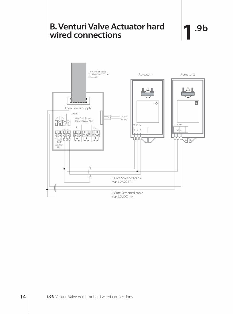
1.9bB. Venturi Valve Actuator hardwired connections
1.9B Venturi Valve Actuator hard wired connections

15
Seller warrants that this product, under normal use and service as described in the operator’s manual shall be free from defects in workmanship and material for a period of twelve (12) months, or the length of time specified in the operator’s manual, from the date of shipment to the customer. This limited warranty is subject to the following exclusion :
a . Batteries and certain other components when indicated in specifications are warranted for a period of 90 days from the date of shipment to the customer.
b. With respect to any repair services rendered, Seller warrants that the parts repaired or replaced will be free from defects in workmanship and material, under normal use, for a period of 90 days from the date of shipment to the customer.
c . Seller does not provide any warranty on finished goods manufactured by others. Only the original manufacturer’s warranty applies.
d . Unless specifically authorised in a separate writing by Seller, Seller makes no warranty with respect to, and shall have no liability in connection with, any goods which are incorporated into other products or equipment by the Buyer. All goods returned under warranty shall be at the Buyer’s risk of loss, Seller’s factory prepaid, and will be returned at Seller’s risk of loss, Buyer’s factory prepaid.
The foregoing is in lieu of all other warranties and is subject to the conditions and limitations stated herein. No other express or implied warranty of fitness for particular purpose or merchantability is made. The exclusive remedy of the user or purchaser, and the limit of liability of seller for any and all losses, injuries, or damages in connection with this product ( including claims based on contract negligence, strict liability, other tort, or otherwise ) shall be the return of the product to the factory or designated location and the refund of the purchase price, or, at the option of the seller, the repair or replacement of the product. in no event shall seller be liable for any special, incidental or consequential damages.seller shall not be responsible for installation, dismantling, reassembly or reinstallation costs or charges. No action, regardless of form, may be brought against the seller more than one year after the cause of action has accrued.The purchaser and all users are deemed to have accepted the terms of this limitation of warranty and liability, which contains the complete and exclusive limited warranty of Seller. This limitation of warranty and liability may not be amended or modified nor may any of its terms be waived except by a writing signed by an authorised representative of the Seller.
2.0Limitation of Warranty and Liability
2.0 Limitation of Warranty and Liability


Temperature Electronics Ltd.Unit 2, Wren Nest Road, Glossop,
SK13 8HB United Kingdom
Tel: +44 (0)1457 865635 Fax: +44 (0)1457 868843


